![Performance and failure of metal sandwich plates subjected ... · Keywords: sandwich plates, honeycomb core, folded plate core, strength, ductility, ... [Liang et al. 2007], two types](https://static.fdocuments.net/doc/165x107/5b14a9907f8b9a487c8e2ec3/performance-and-failure-of-metal-sandwich-plates-subjected-keywords-sandwich.jpg)
Stiffness and Failure behaviour of folded sandwich cores ...
19
Stiffness and Failure behaviour of folded sandwich cores under combined transverse shear and compression CompTest Conference 2006 D. Hartung, M. Kintscher, L. Kärger, A. Wetzel
Transcript of Stiffness and Failure behaviour of folded sandwich cores ...
Stiffness and Failure behaviour of folded sandwich cores under combined transverse shear and compression
CompTest Conference 2006
D. Hartung, M. Kintscher, L. Kärger, A. Wetzel
Institute of Composite Structures and Adaptive Systems 2
Contents
Folded core material description
Test setup and configuration
Test results by single and combined shear and compressive loads
Evaluation of a failure criteria
Conclusion
Institute of Composite Structures and Adaptive Systems 3
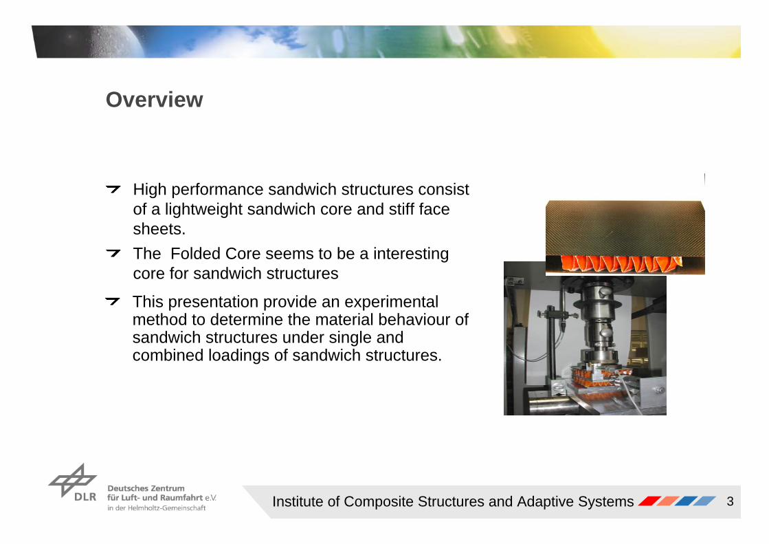
Overview
High performance sandwich structures consist of a lightweight sandwich core and stiff face sheets. The Folded Core seems to be a interesting core for sandwich structures
This presentation provide an experimental method to determine the material behaviour of sandwich structures under single and combined loadings of sandwich structures.
Institute of Composite Structures and Adaptive Systems 4
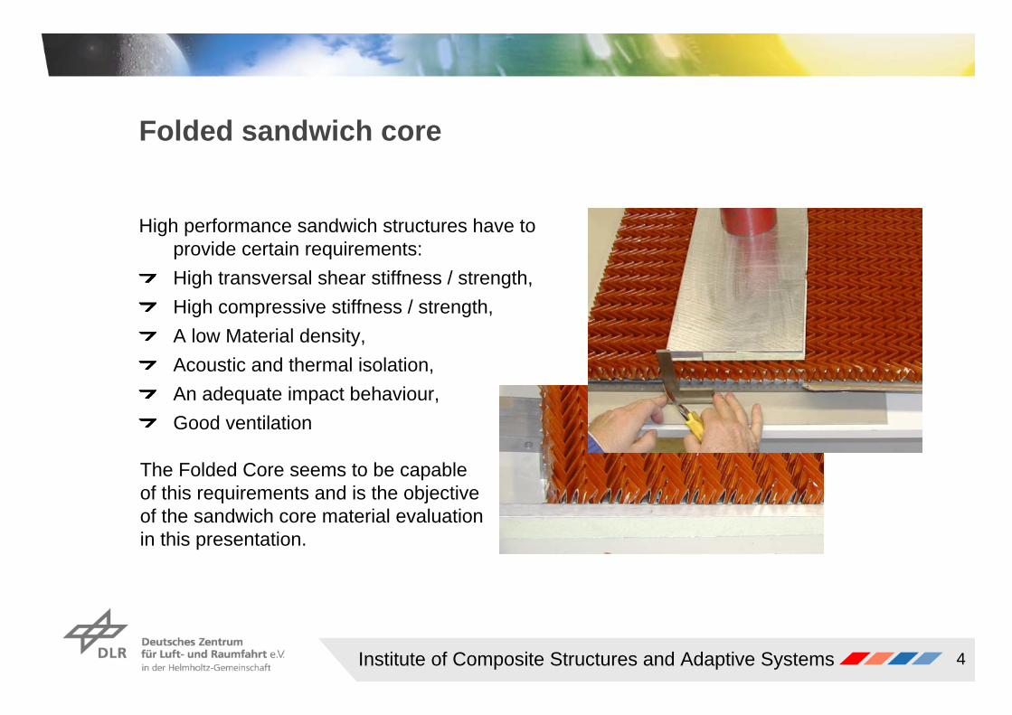
Folded sandwich core
High performance sandwich structures have to provide certain requirements:High transversal shear stiffness / strength,High compressive stiffness / strength,A low Material density,Acoustic and thermal isolation,An adequate impact behaviour,Good ventilation
The Folded Core seems to be capable of this requirements and is the objective of the sandwich core material evaluation in this presentation.
Institute of Composite Structures and Adaptive Systems 5
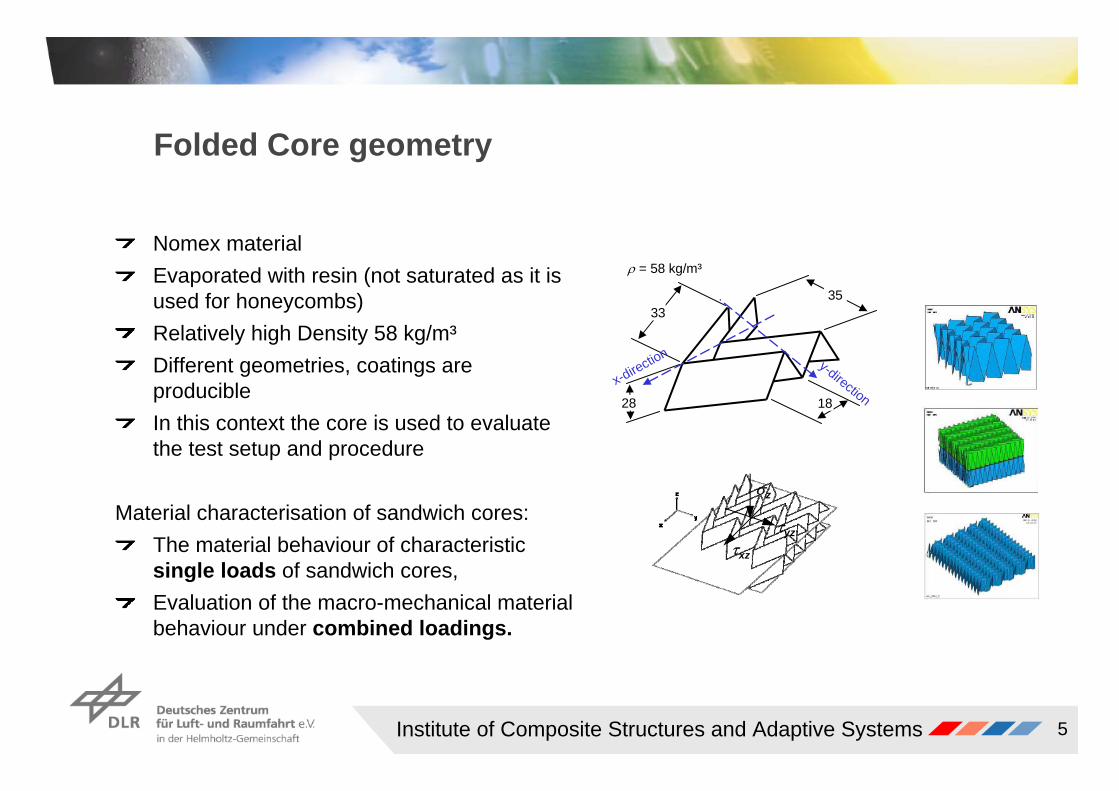
Folded Core geometry
Nomex materialEvaporated with resin (not saturated as it is used for honeycombs)Relatively high Density 58 kg/m³Different geometries, coatings are producibleIn this context the core is used to evaluate the test setup and procedure
Material characterisation of sandwich cores:The material behaviour of characteristic single loads of sandwich cores,Evaluation of the macro-mechanical material behaviour under combined loadings.
x-direction y-direction
ρ = 58 kg/m³
33
28
35
18
σz
τxz
τyz
Institute of Composite Structures and Adaptive Systems 6
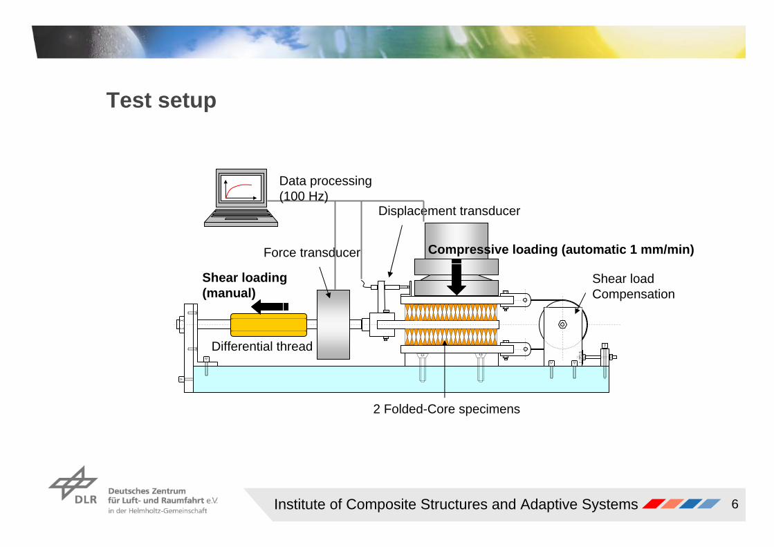
Test setup
Shear loading (manual)
Compressive loading (automatic 1 mm/min)
Specimen
Displacement transducer
Differential thread
Shear loadCompensation
2 Folded-Core specimens
Force transducer
Data processing (100 Hz)
Institute of Composite Structures and Adaptive Systems 7
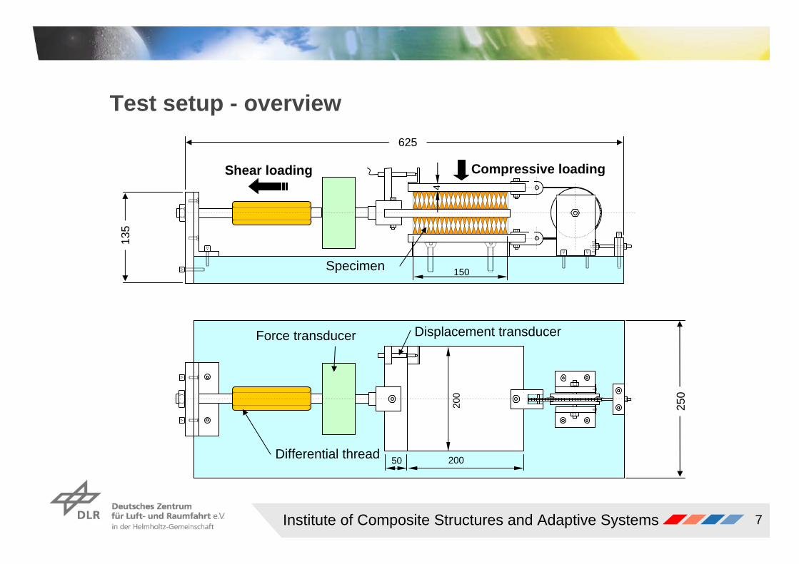
Test setup - overview
Shear loading Compressive loading
Differential thread
Force transducer
Specimen
Displacement transducer
135
250
625
200
20050
150
4
Institute of Composite Structures and Adaptive Systems 8
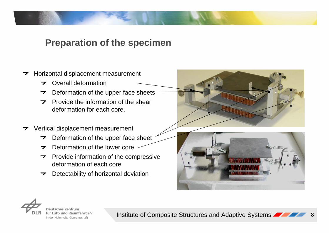
Preparation of the specimen
Horizontal displacement measurementOverall deformationDeformation of the upper face sheetsProvide the information of the shear deformation for each core.
Vertical displacement measurementDeformation of the upper face sheetDeformation of the lower core Provide information of the compressive deformation of each core Detectability of horizontal deviation
Institute of Composite Structures and Adaptive Systems 9
Problems and improvements of the test setup
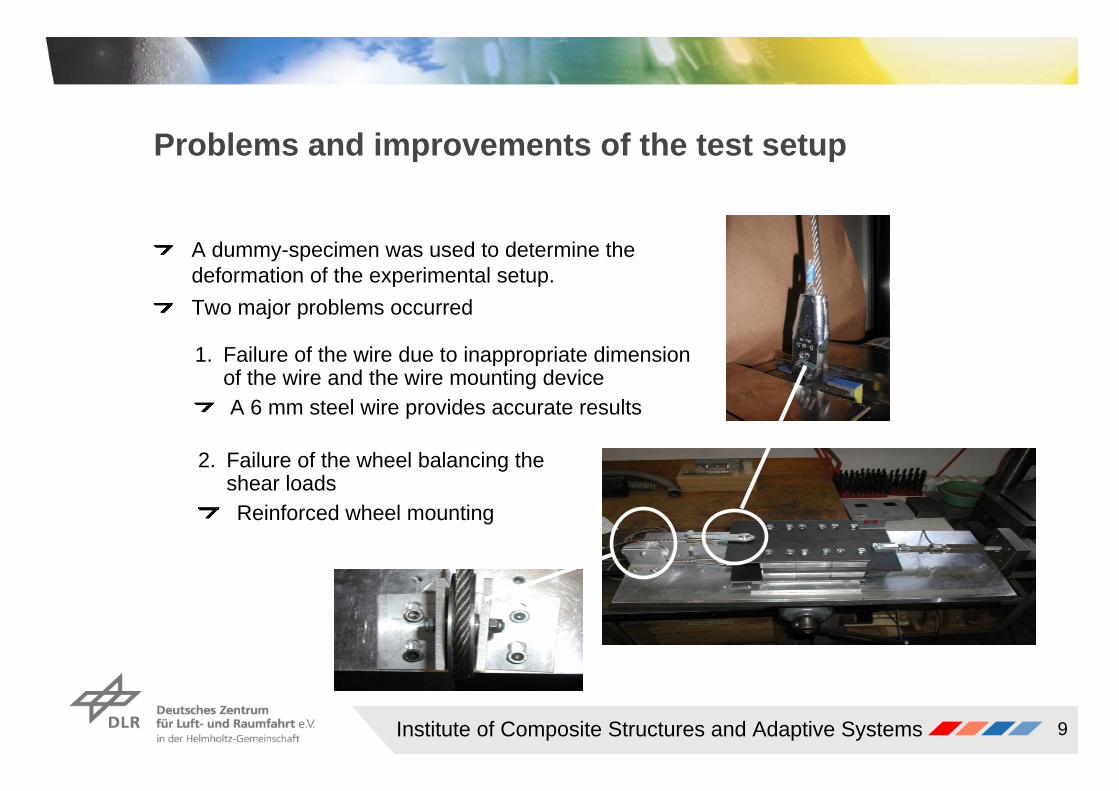
A dummy-specimen was used to determine the deformation of the experimental setup.Two major problems occurred
1. Failure of the wire due to inappropriate dimension of the wire and the wire mounting deviceA 6 mm steel wire provides accurate results
2. Failure of the wheel balancing the shear loadsReinforced wheel mounting
Institute of Composite Structures and Adaptive Systems 10
Results of a single shear loading
Strain
Shea
r Stre
ss [N
/mm
²]
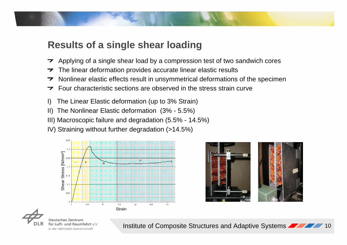
II) The Nonlinear Elastic deformation (3% - 5.5%)III) Macroscopic failure and degradation (5.5% - 14.5%)IV) Straining without further degradation (>14.5%)
I) The Linear Elastic deformation (up to 3% Strain)
Applying of a single shear load by a compression test of two sandwich coresThe linear deformation provides accurate linear elastic results Nonlinear elastic effects result in unsymmetrical deformations of the specimenFour characteristic sections are observed in the stress strain curve
Institute of Composite Structures and Adaptive Systems 11
Shear failure results
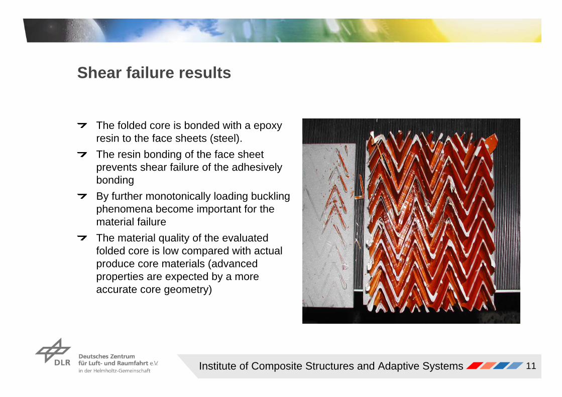
The folded core is bonded with a epoxy resin to the face sheets (steel).The resin bonding of the face sheet prevents shear failure of the adhesively bondingBy further monotonically loading buckling phenomena become important for the material failure The material quality of the evaluated folded core is low compared with actual produce core materials (advanced properties are expected by a more accurate core geometry)
Institute of Composite Structures and Adaptive Systems 12
Strain [%]
Com
pres
sive
Stre
ss [N
/mm
²]
Results of a single compressive loading
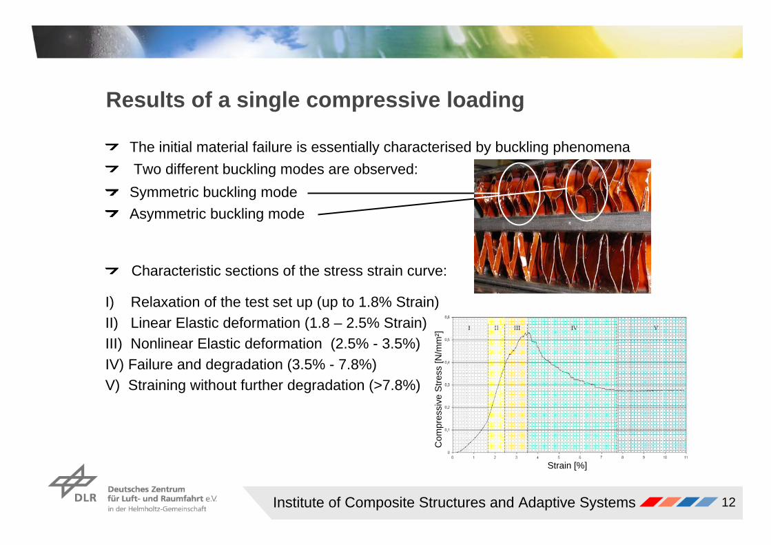
The initial material failure is essentially characterised by buckling phenomenaTwo different buckling modes are observed:
Asymmetric buckling modeSymmetric buckling mode
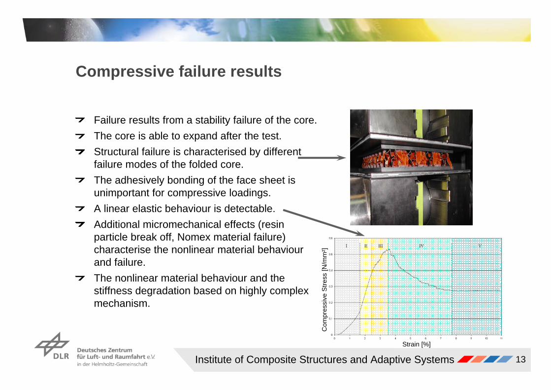
Characteristic sections of the stress strain curve:
III) Nonlinear Elastic deformation (2.5% - 3.5%)IV) Failure and degradation (3.5% - 7.8%)V) Straining without further degradation (>7.8%)
II) Linear Elastic deformation (1.8 – 2.5% Strain)I) Relaxation of the test set up (up to 1.8% Strain)
Institute of Composite Structures and Adaptive Systems 13
Compressive failure results
Failure results from a stability failure of the core. The core is able to expand after the test. Structural failure is characterised by different failure modes of the folded core.The adhesively bonding of the face sheet is unimportant for compressive loadings.A linear elastic behaviour is detectable.Additional micromechanical effects (resin particle break off, Nomex material failure) characterise the nonlinear material behaviour and failure.The nonlinear material behaviour and the stiffness degradation based on highly complex mechanism.
Strain [%]
Com
pres
sive
Stre
ss [N
/mm
²]
Institute of Composite Structures and Adaptive Systems 14
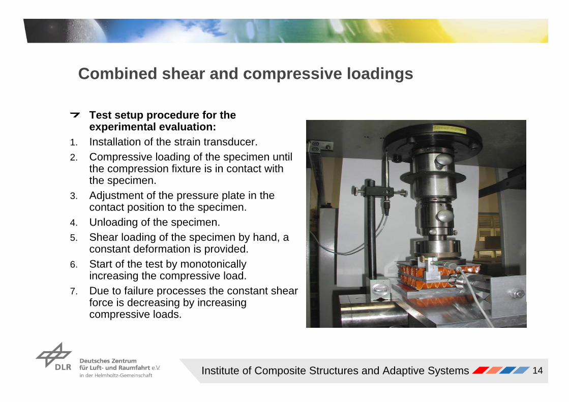
Combined shear and compressive loadings
Test setup procedure for the experimental evaluation:
1. Installation of the strain transducer.2. Compressive loading of the specimen until
the compression fixture is in contact with the specimen.
3. Adjustment of the pressure plate in the contact position to the specimen.
4. Unloading of the specimen.5. Shear loading of the specimen by hand, a
constant deformation is provided. 6. Start of the test by monotonically
increasing the compressive load. 7. Due to failure processes the constant shear
force is decreasing by increasing compressive loads.
Institute of Composite Structures and Adaptive Systems 15
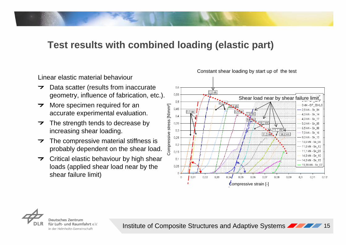
Test results with combined loading (elastic part)
Linear elastic material behaviourData scatter (results from inaccurate geometry, influence of fabrication, etc.).More specimen required for an accurate experimental evaluation.The strength tends to decrease by increasing shear loading.The compressive material stiffness is probably dependent on the shear load.Critical elastic behaviour by high shear loads (applied shear load near by the shear failure limit)
Compressive strain [-]
Com
pres
sive
stre
ss [N
\mm
²]
Constant shear loading by start up of the test
Shear load near by shear failure limit
Institute of Composite Structures and Adaptive Systems 16
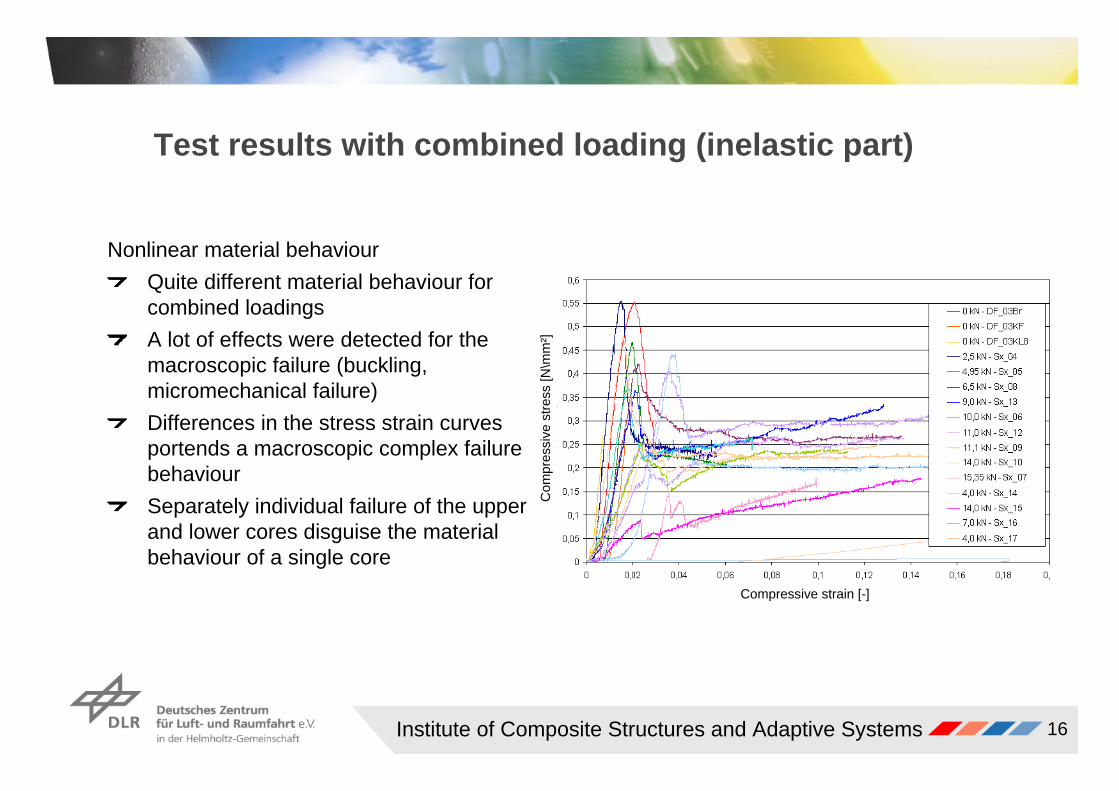
Test results with combined loading (inelastic part)
Nonlinear material behaviourQuite different material behaviour for combined loadingsA lot of effects were detected for the macroscopic failure (buckling, micromechanical failure)Differences in the stress strain curves portends a macroscopic complex failure behaviourSeparately individual failure of the upper and lower cores disguise the material behaviour of a single core
Compressive strain [-]
Com
pres
sive
stre
ss [N
\mm
²]
Institute of Composite Structures and Adaptive Systems 17
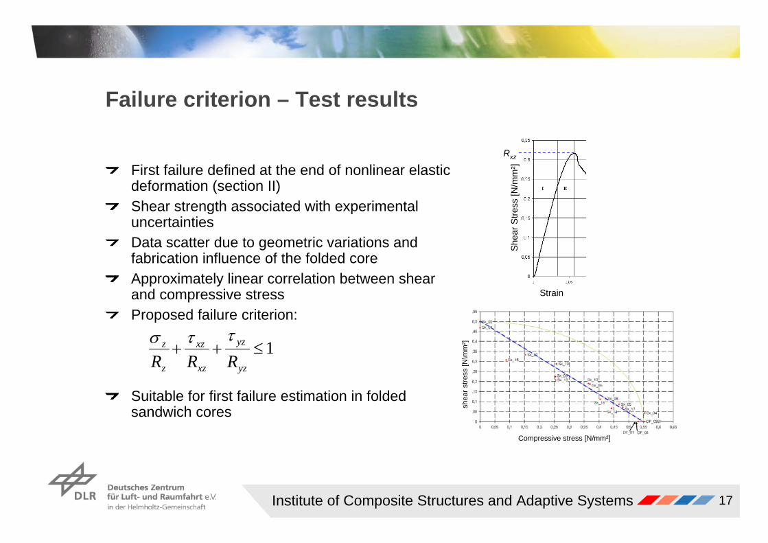
Failure criterion – Test results
First failure defined at the end of nonlinear elastic deformation (section II)Shear strength associated with experimental uncertainties Data scatter due to geometric variations and fabrication influence of the folded core Approximately linear correlation between shear and compressive stressProposed failure criterion:
Suitable for first failure estimation in folded sandwich cores
Compressive stress [N/mm²]
shea
r stre
ss [N
\mm
²] 1≤++yz
yz
xz
xz
z
z
RRRττσ
Strain
Shea
r Stre
ss [N
/mm
²]
Rxz

Institute of Composite Structures and Adaptive Systems 18
Conclusion
AdvantageousIt has been shown that this simple test setup provide appropriate results concerning a first failure estimation and material characterisation.The test setup provides appropriate results for linear elastic deformation and macroscopic failure.Good results achievable for combined loadings up to moderate shear loading (relatively high shear loadings results in failure before relevant compressive loads are applied)
Disadvantageous The results dependent of the separated failure behaviour of two folded coresThe test setup provides only a constant shear loading
Interesting improvements Biaxial test machine for monotonic increasing compressive and shear loadings

Institute of Composite Structures and Adaptive Systems 19
Acknowledgement
This presentations was provided by the work of Markus Kintscher and Luise Kärgerof the DLR (German Aerospace Center) in Braunschweig.
The folded sandwich core material was provided by Airbus Germany
Thank you for your attention