STG Decomposition: Avoiding Irreducible CSC Conflicts...
54
STG Decomposition: Avoiding Irreducible CSC Conflicts by Internal Communication Dominic Wist, Ralf Wollowski Technische Berichte Nr. 20 des Hasso-Plattner-Instituts für Softwaresystemtechnik an der Universität Potsdam
Transcript of STG Decomposition: Avoiding Irreducible CSC Conflicts...
STG Decomposition: Avoiding Irreducible CSC Conflictsby Internal Communication
Dominic Wist, Ralf Wollowski
Technische Berichte Nr. 20des Hasso-Plattner-Instituts für Softwaresystemtechnik an der Universität Potsdam


Technische Berichte des Hasso-Plattner-Instituts für Softwaresystemtechnik
an der Universität Potsdam
Nr. 20
STG Decomposition: Avoiding Irreducible CSC Conflicts by Internal Communication
Dominic Wist, Ralf Wollowski
Potsdam 2007

Bibliografische Information Der Deutschen Nationalbibliothek Die Deutsche Nationalbibliothek verzeichnet diese Publikation in der Deutschen Nationalbibliografie; detaillierte bibliografische Daten sind im Internet über http://dnb.d-nb.de abrufbar Die Reihe Technische Berichte des Hasso-Plattner-Instituts für Softwaresystemtechnik an der Universität Potsdam erscheint aperiodisch. Herausgeber: Redaktion: E-Mail: Verlag: Druck:
Professoren des Hasso-Plattner-Instituts für Softwaresystemtechnik an der Universität Potsdam Dominic Wist, Ralf Wollowski {dominic.wist; ralf.wollowski}@.hpi.uni-potsdam.de Universitätsverlag Potsdam Am Neuen Palais 10 14469 Potsdam Fon +49 (0) 331 977 4517 Fax +49 (0) 331 977 4625 e-mail: ubpub@uni-potsdamde http://info.ub.uni-potsdam.de/verlag.htm allprintmedia gmbH Blomberger Weg 6a 13437 Berlin email: [email protected]
© Hasso-Plattner-Institut für Softwaresystemtechnik an der Universität Potsdam, 2007 Dieses Manuskript ist urheberrechtlich geschützt. Es darf ohne vorherige Genehmigung der Herausgeber nicht vervielfältigt werden. Heft Nr 20 (2007) ISBN 978-3-940793-02-7 ISSN 1613-5652

STG Decomposition:Avoiding Irreducible CSC Conflicts
by Internal Communication
Dominic Wist, Ralf Wollowski
[email protected], [email protected]
For the logic synthesis of complex asynchronous controllers a decomposition basedtechnique has been proposed. It is based on a structural STG decomposition method[21,25,26] and the speed independent logic synthesis [9]. But the decomposition maylead to component STGs with irreducible CSC conflicts (i.e. components that cannotbe implemented as speed independent circuits). An idea is presented to avoid suchirreducible CSC conflicts in component STGs by the introduction of internal communi-cation among the corresponding component circuits. Furthermore, first concepts for asystematization are presented, based on the structural theory of Petri nets. The suit-ability of the approach is demonstrated by means of two examples (a FIFO controllerand a sequencer/parallelizer tree).
1 Introduction
Nowadays, the semiconductor industry gives serious consideration to the adoption ofasynchronous circuit technology. During the last decade, first entirely asynchronousICs appeared on the market [11,24]. In comparison to their synchronous counterpartsthe opportunities of asynchronous systems are high performance, low power consump-tion, better electromagnetic compatibility (EMC), modularity and the lack of clock skew.In spite of their proved benefits, the asynchronous design style is not fully acceptedamongst designers of synchronous circuitry. The major drawback is the insufficientmaturity level of existing CAD tools for their synthesis and verification.
For many years several research groups developed methods and tools for asyn-chronous system design. So far the most successful initiatives have been those guar-anteeing a robust implementation of complex specifications at the expense of theirefficiency. These methods are based on syntax-directed translation from some highlevel language such as TANGRAM [23] or BALSA [2].
The syntax-directed translation paradigm is characterized by the translation of eachstatement of the high-level design-entry language into a so-called handshake compo-nent (HC). Thus the entire entry language program is translated into a netlist of com-municating handshake components. Each HC is a handmade circuit, i.e. designed andoptimized by hand without the aid of a CAD tool. As this paradigm supports the de-signers with a programming language design entry it fits well to the established design
1-1

STG Decomposition: Avoiding Irreducible CSC Conflicts by Internal Communication
flow for synchronous systems.1 A further advantage of this paradigm is that it does notsuffer from the state explosion problem, since the analysis of the whole state space ofa highly concurrent system is not necessary. But syntax-directed translation can leadto inefficient implementations since logic synthesis is not applied (i.e. the power ofboolean minimization techniques).
Thus a desirable aim is to overcome these drawbacks by the incorporation of logicsynthesis into a design flow based on syntax-directed translation – and raise the com-petitiveness of the syntax-directed translation approach to achieve results comparableto those obtained by the current design flows in synchronous design. First promisingresults of this approach are presented in [5]. On this account we consider an EDAframework as shown Figure 1 (as proposed in a similar way e.g. in [6, 28]) that com-bines logic synthesis (for the entire control path) and syntax-directed translation (forthe data path).
Due to the separate design of control and data path, we divide handshake com-ponents into plain data path, plain control and mixed components, as proposed in [1].Then the control extraction can be realized by the transformation of each control com-ponent and parts of each mixed component (i.e. the control behavior part, see [1]) intosignal transition graphs (STGs) – the so-called HC-STGs. The remaining part of eachmixed component together with the plain data path components form the entire datapath of the asynchronous system.
In order to exploit the power of a global logic synthesis for the entire control path,all handshake component STGs are composed into one complex controller STG N (byparallel composition, see Section 2.3). A significant reduction in the complexity of Ncan be reached by the contraction of transitions that only model internal HC commu-nication among the handshake components. Anyway, this reduced N is usually stillcomplex; on this account it is often impossible to generate its whole state space whichis needed for the application of logic synthesis (state explosion problem). In order toovercome the state explosion problem a structural STG decomposition as introducedin [5, 26, 29] has been proposed. After this decomposition the component STGs aresubject to one of the well-known logic synthesis approaches such as the SI synthesismethod [9] or the synthesis based on (extended) burst mode machines [19,30,31].
The proposed design framework still has certain gaps (i.e. components that are notinvestigated so far, represented as rectangles with dashed borders in Figure 1). Thedesign of these components is subject of future work.
As a contribution to complete the proposed EDA framework the aim of the presentedwork is to combine the decomposition approach of Vogler et al. [21, 25, 26] with the SIlogic synthesis approach [9]. In fact, there are other STG decomposition approaches[5,29], but – in contrast to the decomposition method used here – these approaches areonly applicable for STGs having the complete state coding (CSC) property (i.e. a givenSTG has to be transformed into an STG satisfying CSC as a precondition). However,the decomposition methods of [5, 29] guarantee that the resulting components alsosatisfy CSC and thus a speed independent logic synthesis is directly possible. But the
1 Recently, C-like languages such as SPECC or SYSTEMC attract the attention of synchronous circuitdesigners, since they completely abstract from the (HW-)implementation. Hence, it is a promising futuretopic to investigate the translation of SPECC or SYSTEMC descriptions into asynchronous systems.
1-2

1 INTRODUCTION
HC netlist(e.g. breeze netlist)
syntax-directed
synthesis
control and
data path
extraction
data path
decomposition based
logic synthesis
SI synthesizers (or others)
control
high level language
asynchronous system specification(e.g. in Balsa or Tangram)
handshake component
synthesizer(e.g. Balsa System)
Tech.
mapper(e.g. Balsa
Backend)
STG generator(control extraction)
complex controller STG N
structural decomposer
component
STG C1
component
STG C2
component
STG Cn
logic
synthesizer
logic
synthesizer
logic
synthesizer
netlist 1 netlist 2 netlist n netlist n+m+1
plain
control
components
libra
ry
plain
data path
components
transformerSpecC,
SystemC
STG composer
HC-STG1 HC-STGk
preprocessors
mixed
components
internal handshake eliminator
logic generator(data path extraction)
netlist
n+1
Tech.
Mapper(e.g.
Synopsis) libra
ry
logic
circuit
reduced controller STG N’
Figure 1: Proposed EDA framework for asynchronous systems (components with dashed bor-ders are not investigated so far)
1-3
STG Decomposition: Avoiding Irreducible CSC Conflicts by Internal Communication
methods [5,29] only deal with total decompositions, i.e. they generate a component foreach single output signal, while the chosen decomposition method of Vogler et al. isable to handle components with more than one output signal – which can lead to betterresults (e.g. by means of the size of the component STGs given by the cumulatednumber of their reachable markings [21]). Further, for the decomposition approachin [29] a formal definition as well as a correctness proof is missing so far.
However, the decomposition according to Vogler et al. of an SI implementable STGN may lead to component STGs Ci with irreducible CSC conflicts even though theoverall STG has none (i.e. Ci cannot be implemented as a speed independent cir-cuit). This work tackles this problem and presents an idea and first concepts to avoidirreducible CSC conflicts in component STGs resulting from an STG decompositionaccording to Vogler et al. by the suitable introduction of internal communication amongthe component circuits. In this context, it provides a basis for the implementation of thepreprocessors in Figure 1.
A further contribution of this work is to break down the problem of solving CSCconflicts for large and complex STGs (which is rather inefficient so far) to the solutionof CSC conflicts in several smaller and less complex component STGs (which can behandled quite efficiently).
The organization of the paper is as follows: In the next Section some basic defini-tions are introduced. In Section 3, the motivation and the idea for avoiding irreducibleCSC conflicts in component STGs by the introduction of internal communication is pre-sented. First concepts for a systematization, i.e. considerations towards a structuralmethod for the implementation of such an internal communication are given in Section4. Section 5 demonstrates the suitability of the proposed method by means of two ex-amples: a FIFO controller and a handshake circuit derived from a BALSA specification(a sequencer/parallelizer tree). Finally, we give our conclusions and – since this workintroduces first concepts only – an outlook for future work in Section 6.
2 Basic Definitions
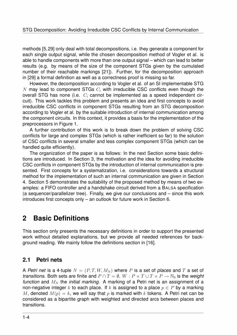
This section only presents the necessary definitions in order to support the presentedwork without detailed explanations, but we provide all needed references for back-ground reading. We mainly follow the definitions section in [16].
2.1 Petri nets
A Petri net is a 4-tuple N = (P, T,W,MN) where P is a set of places and T a set oftransitions. Both sets are finite and P ∩ T = ∅. W : P × T ∪ T × P → N0 is the weightfunction and MN the initial marking. A marking of a Petri net is an assignment of anon-negative integer k to each place. If k is assigned to a place p ∈ P by a markingM , denoted M(p) = k, we will say that p is marked with k tokens. A Petri net can beconsidered as a bipartite graph with weighted and directed arcs between places andtransitions.
1-4

2 BASIC DEFINITIONS
Given a place or transition x ∈ P ∪ T , its postset and preset are denoted by •x andx• resp. A transition t ∈ T is enabled under a marking M , denoted by M [t〉, if each
place p in •t is marked with M(p) ≥ W (p, t). When a transition t is enabled, it can fire,yielding a new marking M ′ with M ′(p) = M(p) −W (p, t) + W (t, p) for all p ∈ P . Wedenote this by M [t〉M ′.
A transition sequence v = t0t1...tn is enabled under a marking M (yielding M ′) ifM [t0〉M0[t1〉M1...Mn−1[tn〉Mn = M ′, denoted M [v〉 or M [v〉M ′ resp. If MN [v〉 holds thenv is called a firing sequence. By the way, the empty transition sequence λ is enabledunder every marking.
M is called reachable if a transition sequence v with MN [v〉M exists. We onlyconsider Petri nets N such that the set [MN〉 of reachable markings is finite i.e. N isbounded. A Petri net is k-bounded or simply bounded if for every reachable markingM and every place p ∈ P , M(p) ≤ k. A Petri net is safe if it is 1-bounded.
A Petri net N is called live iff in any reachable marking M for all transitions t ∈ T atransition sequence v exists with M [v〉M ′[t〉.
A Petri net N with a initial marking MN is said to be reversible if for each reachablemarking M ∈ [MN〉, MN is reachable from M ; thus in a reversible net one can alwaysget back to the initial marking.
2.2 Signal Transition Graphs and Complete State Coding (CSC)
A Signal Transition Graph (STG) is a tuple N = (P, T,W,MN , In,Out, Int, l) where(P, T,W,MN) is a Petri net and In, Out and Int are disjoint sets of input, output andinternal signals. We define the set of all signals Sig := In ∪ Out ∪ Int, the set oflocal signals Loc := Out ∪ Int and the set of all external signals Ext := In ∪ Out.l : T → Sig × {+,−} ∪ {λ} is the labeling function. Sig × {+,−} or (for short) Sig± isthe set of signal edges or signal transitions; its elements are denoted as s+, s− resp.(short for (s,+), (s,−) resp.). While the plus sign denotes a rising, the minus signdenotes a falling signal edge. We write s± if it is not important or unknown which signaledge takes place; if such a term appears more than once in the same context, it alwaysdenotes the same direction. For a short notation, input (output) signal edges are justcalled input (output) edges. An STG may initially contain transitions labeled with theempty word λ called dummy -transitions. They are only a design simplification and donot correspond to a signal transition (i.e. describe no physical reality).
An example of an STG is shown in Figure 2a. Places are drawn as circles containingthe number of tokens according to their initial marking. Unmarked places with only onetransition in their preset and postset resp. can be omitted if the corresponding arcsare weighted with 1 (short-hand notation), i.e. these places are implicitly given by anarc between these two transitions. Transitions are drawn as boxes together with theirlabeling and the weight function as directed arcs xy labeled with W (x, y) if W (x, y) > 1.
We lift the notion of enabledness to transition labels: M [l(t)〉〉M ′ if M [t〉M ′. Thisis extended to sequences as usual – deleting λ labels automatically (e.g. M [s±〉〉M ′
means that a sequence of transitions fires, where one of them is labeled s± while theothers are λ-labeled). A sequence v of elements of Sig± is called a trace of a marking
1-5

STG Decomposition: Avoiding Irreducible CSC Conflicts by Internal Communication
a+
y+
a-
z+
b+
y- z-
b-
(a) STG N
INPUTS: a,bOUTPUTS: y,z
0000
1000
a+
0100
b-
1001
z+
1010
y+
1011
y+
1101
b+
0110
y-
0101
z-
z+
0010
a-
1111
b+
0011
a-y+
1100
z-
1110
a-
0111
z- y-
0001
b+
z+
0000
y-z- a-y+ b+ y- z+
(b) State graph
Figure 2: STG example with its corresponding state graph
M if M [v〉〉, and a trace of STG N if MN [v〉〉. The language L(N) of N is the set of alltraces of N .
An STG is called consistent if for each signal s the edges s+ and s− alternate inall traces, always beginning with the same signal edge. Only from consistent STGs acircuit can be synthesized.
An STG has auto-concurrency if there are distinct transitions t1 and t2 with l(t1) =l(t2) 6= λ such that for some reachable marking M ∀p ∈ P : M(p) ≥ W (p, t1) +W (p, t2).
An STG has a dynamic conflict if there are distinct transitions t1 and t2 such that forsome reachable marking M : M [t1〉 and M [t2〉, but ∃p ∈ P : M(p) < W (p, t1) +W (p, t2).A dynamic conflict implies a structural conflict, i.e. •t1 ∩
•t2 6= ∅. The conflict is called
an auto-conflict if l(t1) = l(t2) 6= λ.The reachability graph RGN of an STG N is an edge-labeled directed graph on the
reachable markings with MN as root; there is an edge from M to M ′ labeled l(t) when-ever M [t〉M ′. RGN can be seen as a finite automaton where all states are accepting,and L(N) is the language of this automaton. N is deterministic if its reachability graphis deterministic, i.e. if it contains no λ transitions and if for each reachable marking Mand each signal edge s± there is at most one M ′ with M [s±〉〉M ′.
Let RGN be the reachability graph of an STG N . A state vector is a function sv :Sig → {0, 1} where ’0’ means logical low and ’1’ logical high. A state assignmentassigns the corresponding state vector to each marking M of RGN denoted by svM .
In Figure 2b the corresponding reachability graph of the STG in 2a is shown, anno-tated with its state assignment. This graph is usually called the state graph (and eachof its nodes a state). The node highlighted by the double line border represents theroot node (i.e. the initial marking).
A consistent STG N has Complete State Coding (CSC) if no two reachable mark-ings M1 and M2 with the same state vector exist that enable the same output signals.Otherwise, N has a CSC conflict between M1 and M2. The STG in Figure 2a or itsstate graph in Figure 2b resp. has such a CSC conflict between the gray marked states
1-6
2 BASIC DEFINITIONS
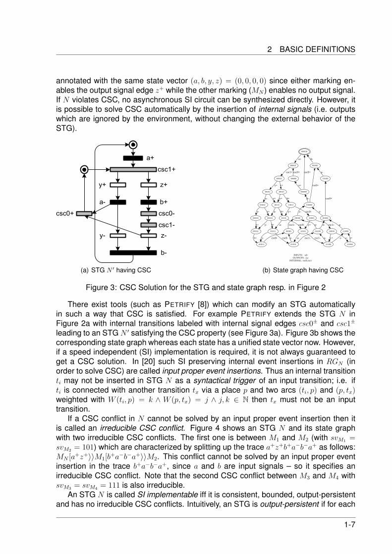
annotated with the same state vector (a, b, y, z) = (0, 0, 0, 0) since either marking en-ables the output signal edge z+ while the other marking (MN ) enables no output signal.If N violates CSC, no asynchronous SI circuit can be synthesized directly. However, itis possible to solve CSC automatically by the insertion of internal signals (i.e. outputswhich are ignored by the environment, without changing the external behavior of theSTG).
csc1+
y+
a-
z+
b+
y- z-
b-
a+
csc0-
csc1-
csc0+
(a) STG N ′ having CSC
INPUTS: a,bOUTPUTS: y,z
INTERNAL: csc0,csc1
000010
100010
a+
010010
b-
100011
csc1+
011010
y-
101011
y+
100111
z+
100000
csc0+
000000
csc0+
a+
001011
a-
101111
z+ y+
110111
b+
010000
csc0+
b-
001111
z+
000011
y- a-
111111
b+
110101
csc0-y+
010100
z-
011000
csc0+
y-
111101
y+
110100
csc1-
011111
b+
000111
y-z+ csc0-a-
010101
csc1-
011100
y- z-
111100
csc1-
011101
a- y+
110000
z-
010111
y- csc0-b+
111000
a-
a- z- y+csc0- y- csc1-
(b) State graph having CSC
Figure 3: CSC Solution for the STG and state graph resp. in Figure 2
There exist tools (such as PETRIFY [8]) which can modify an STG automaticallyin such a way that CSC is satisfied. For example PETRIFY extends the STG N inFigure 2a with internal transitions labeled with internal signal edges csc0± and csc1±
leading to an STG N ′ satisfying the CSC property (see Figure 3a). Figure 3b shows thecorresponding state graph whereas each state has a unified state vector now. However,if a speed independent (SI) implementation is required, it is not always guaranteed toget a CSC solution. In [20] such SI preserving internal event insertions in RGN (inorder to solve CSC) are called input proper event insertions. Thus an internal transitionti may not be inserted in STG N as a syntactical trigger of an input transition; i.e. ifti is connected with another transition tx via a place p and two arcs (ti, p) and (p, tx)weighted with W (ti, p) = k ∧ W (p, tx) = j ∧ j, k ∈ N then tx must not be an inputtransition.
If a CSC conflict in N cannot be solved by an input proper event insertion then itis called an irreducible CSC conflict. Figure 4 shows an STG N and its state graphwith two irreducible CSC conflicts. The first one is between M1 and M2 (with svM1 =svM2 = 101) which are characterized by splitting up the trace a+z+b+a−b−a+ as follows:MN [a+z+〉〉M1[b
+a−b−a+〉〉M2. This conflict cannot be solved by an input proper eventinsertion in the trace b+a−b−a+, since a and b are input signals – so it specifies anirreducible CSC conflict. Note that the second CSC conflict between M3 and M4 withsvM3 = svM4 = 111 is also irreducible.
An STG N is called SI implementable iff it is consistent, bounded, output-persistentand has no irreducible CSC conflicts. Intuitively, an STG is output-persistent if for each
1-7

STG Decomposition: Avoiding Irreducible CSC Conflicts by Internal Communication
a+
b+
a-
b-
z-
z+
(a) STG
INPUTS: a,bOUTPUTS: z
000
100
a+
110
b+
101
z+
111
z+b+
111
z-
011
a-
001
b-
101
z-
b+
z-
a+
(b) State Graph
Figure 4: Example STG having irreducible CSC conflicts
output signal holds that its transitions are not disabled by transitions of another signaland input signals cannot be disabled by outputs. Output persistency therefore onlyallows input events to be in direct conflict (thus modeling non-deterministic choice inthe environment). More detailed information about SI implementability is given e.g.in [9].
This report proposes a new idea to avoid irreducible CSC conflicts in componentSTGs resulting from STG decomposition which is briefly introduced in the next section.
2.3 STG Decomposition
To cope with the state explosion problem during logic synthesis of a complex STG itsdecomposition has been proposed. As outlined in Figure 5, the decomposition used inthis work [25, 26] is based on the partition of the output signals in such a way that foreach partition block one component STG will be extracted from the overall STG. This isrealized by the application of three reduction operations: transition contraction, deletionof redundant transitions, and deletion of redundant places. Since the component STGsshould be orders of magnitude smaller than the overall STG, logic synthesis of eachSTG component does not suffer from the state explosion problem anymore and leadsto component circuits whose interconnection implements a modular circuit with therequired overall behavior.
In the remainder of this section the reduction operations will be defined. Further-more, a definition of parallel composition will be given, since on one hand it is the basefor the correctness definition of our decomposition approach and on the other hand itspecifies the behavior of the STG composer component in Figure 1. To get more infor-mation of this decomposition method, the reader is invited to take a deeper look in the
1-8

2 BASIC DEFINITIONS
STG
decomposition
Overall STG N
(Out: set of output signals)
(Out)= {B1 ... Bi ... Bn}
component STGs: C1 ... Ci ... Cn
state graphs: SG1 ... SGi ... SGn
component circuits: comp1 ... compi ... compn
modular circuit
output partitioning
component interconnection
reduction operations
logic synthesis
no CSC required,
but SI implementability
SGi << SG of N
Figure 5: Design flow for an STG decomposition based synthesis (according to [21,25,26])
corresponding literature [21,25,26].
We now introduce transition contraction (t-contraction for short, see e.g. [4] for anearly reference), which is the most important reduction operation in our decompositionprocedure. In an STG N , a transition t can be contracted, yielding the STG N , if •t andt• are disjoint and t is not adjacent to an arc with weight greater than 1. The contraction
removes the transition t and replaces •t and t• by their Cartesian product (cf. Figure 6a,b for an example). Each new place (p, p′) inherits the tokens and the connections toother transitions from p and p′.
A contraction is called type-1 (secure) if (•t)• ⊆ {t}, or type-2 (secure) if •(t•) = {t}
and MN(p) = 0 for some p ∈ t•.
a+
b+
x+c+
p1
p2 p3
a+
b+
x+c+
(p1,p3)
(p1,p2)
(a) before contraction (b) after contraction
t-contraction
(of the -labeled
transition t)(t)
Figure 6: Example of a transition contraction
The remaining reduction operations in our decomposition algorithm are the deletionof redundant transitions and of redundant places. A redundant transition is either aλ-transition t, where each place p ∈ •t∪ t• forms a loop with t with two arcs of the sameweight (t is a loop-only transition) or some other transition has arcs to and from thesame places with the same weight and has the same label as t (which is a duplicatetransition). (Structurally) redundant places are defined e.g. in [4]. Such places can bedeleted in a Petri net without changing the firing sequences.
1-9

STG Decomposition: Avoiding Irreducible CSC Conflicts by Internal Communication
These reduction operations and type-1 contractions preserve the behavior in astrong sense:
Proposition 2.1If N ′ is obtained from an STG N by deleting a redundant transition or place or by atype-1 contraction then N and N ′ are bisimilar.
In the following definition of parallel composition ‖, we will have to consider the dis-tinction between input and output signals. The idea of parallel composition is that thecomposed systems run in parallel and synchronize on common signals – correspond-ing to circuits that are connected on signals with the same name. Since a systemcontrols its outputs, we cannot allow a signal to be an output of more than one com-ponent; input signals, on the other hand, can be shared. An output signal of onecomponent can be an input of one or several others, and in any case it is an output ofthe composition. A composition can also be ill-defined due to what e.g. Ebergen [10]calls computation interference; this is a semantic problem, and we will not discuss ithere.
The parallel composition of STGs N1 and N2 is defined if Out1 ∩ Out2 = ∅. LetA = Sig1 ∩ Sig2 be the set of common signals. If e.g. s is an output of N1 and aninput of N2, then an occurrence of an edge s± in N1 is ‘seen’ by N2, i.e. it must beaccompanied by an occurrence of s± in N2. Since we do not know a priori which s±-labeled transition of N2 will occur together with some s±-labeled transition of N1, wehave to allow for each possible pairing. Thus the parallel composition N = N1 ‖ N2 isobtained from the disjoint union of N1 and N2 by combining each s±-labeled transitionof N1 with each s±-labeled transition from N2 if s ∈ A.
Since composition is associative and commutative up to isomorphism, we can de-fine the parallel composition of a finite family (or collection) (Ci)i∈I of STGs as ‖i∈I Ci,provided that no signal is an output signal of more than one of the Ci. Since the placeset of the composition is the disjoint union of the place sets of the components, we canconsider markings of the composition (regarded as multisets) as the disjoint union ofmarkings of the components and write a marking of the composition (Ci)i∈I as a tuple(M1, . . . ,Mn) if Mi is a marking of Ci for i ∈ I = {1, ..., n}. The formal definition and anexample can be found e.g. in [26].
3 Achieving SI Implementability by Internal Commu-nication
This section presents our idea to avoid irreducible CSC conflicts in component STGs –arising through STG decomposition – by the introduction of internal communication.
3.1 Motivation
In order to improve the efficiency (with respect to speed and area) of complex asyn-chronous circuits it has been proposed to generate their control paths by decomposition
1-10

3 ACHIEVING SI IMPLEMENTABILITY BY INTERNAL COMMUNICATION
based logic synthesis (cf. Section 1). To cope with the state explosion problem of com-plex STGs a structural STG decomposition was suggested, firstly by [7, 17], furtherenhanced by [5,29] and [21,25,26].
However, the decomposition according to Vogler et al. [21,25,26] of an overall STGN which has no irreducible CSC conflicts can lead to component STGs having them;consequently, these component STGs are not SI implementable. The next figure il-lustrates this problem. Figure 7a shows a circuit in its overall environment and STG
a+
y+
a-
z+
a+
a-
z+
a+
y+
a-
componentZ
componentY
(overall) environment
z
y
a
overall
circuit
(overall) environment
z
y
a
(c) Overall
STG N(d) STGz (e) STGy
(a) Overall circuit
(b) Component circuits
STG
decom-
position
(t1)
(t2)
(t3)
(t4)
(t1)
(t3)
(t4)
(t1)
(t2)
(t3)
Figure 7: STG decomposition can lead to undesired irreducible CSC conflicts
N in Figure 7c models the circuit’s behavior partially. Observe that (the shown partof) N is SI implementable, i.e. in particular it has no irreducible CSC conflicts. A to-tal decomposition of N – i.e. each component is responsible to generate exactly oneoutput signal (see Figure 7b) – leads to the component STGs in Figure 7d and e. Infact, STGy is SI implementable, but STGz has an CSC conflict (marked by the grayoval), since STGz enables a trace M1[a
+a−〉〉M2 with svM1 = svM2, but only M2 enablesan output transition (t4, labeled with the output edge z+). Moreover, this CSC conflictis irreducible since the only possibility to solve this conflict is to insert internal signaltransitions ‘between’ a+ and a− – but this is not allowed because this would not be aninput proper event insertion.
So the specified behavior of STGz is not SI implementable at all; thus the relatedcircuit component(componentZ) is called critical circuit component and STGz itself crit-ical STG component.
3.2 Idea
The goal now is to avoid such irreducible CSC conflicts arising through STG decom-position without changing the interface behavior (of the overall circuit) and without in-troducing any timing requirements for the environment (as e.g. in the fundamentaloperating mode [22]). Hence, it is an improper modification of STGz to insert t5 (la-beled with ic+) as an output transition in the transition sequence t1t3, as indicated inFigure 8a. In fact, the state vectors of the considered markings which are in CSC con-flict are different now (and of course this would solve the CSC conflict), but the insertion
1-11

STG Decomposition: Avoiding Irreducible CSC Conflicts by Internal Communication
of t5 also demands that the environment must not generate a− until the output edge ic+
occurs which is an improper change of the interface behavior due to SI logic synthesis.Alternatively – as already mentioned in the previous section – the insertion of ic as
an internal signal is an input improper event insertion, i.e. is also an improper changeof the interface behavior. This is because the environment cannot observe, and thuscannot register ic+, i.e. the relation ic+ → a− is not a ‘real’ causal dependence (interms of: the environment observes signal ic, waits for the generation of ic+, and thisenables the environment to generate a−). Consequently, t5 models a desired temporalrelation, i.e. although a− is not caused by ic+, the edge a− should always be generatedafter ic+; if this temporal order is guaranteed, a circuit operation without anomalousbehavior (such as metastability) is possible. In this way componentZ demands a tim-ing requirement from the environment by means of this temporal relation, since (withrespect to the local scope of componentZ due to STGz) the environment generates a−
independently from a reaction of the circuit (i.e. a− can be produced after a+ without re-garding the circuit’s reaction). Observe that an SI circuit can take an uncertain amountof time τ to generate ic+ (unbounded gate delay model). Hence, a circuit designer whoonly knows the specification STGz must take into account that the environment canproduce a− before the end of the time interval τ (i.e. while the circuit is ‘in motion’ –just generating the signal transition ic+ – it can be interrupted by the new input edgea−) and this could lead to anomalous behavior. In order to reach correct behavior, theenvironment ought to delay the generation of a− at least until the end of the time inter-val τ , but as mentioned above, such timing requirements for the environment are notallowed in SI operating mode.
a+
a-
z+
a+
y+
a-
(a) STGz_ic (b) STGy’
ic+ ic+
componentZ’
componentY’
(overall) Environment
z
y
a
(c) Component circuits
ic
(t1)
(t3)
(t4)
(t5)
(t1)
(t2)
(t3)
(t5)
a+
a-
z+
(e) Appoximation of tcb-
concurrency by pseudo-
causality (of tcb-type)
(t1)
(t3)
(t4)
(t5)
tc
ic+
a+
a-
z+
(t1)
(t3)
(t4)
(t5) ic+
(d) precise model: tcb-
concurrency between
ic+ and a-
(dot-dash line: read arc)
Communication
transition
tc
Figure 8: Solution of an irreducible CSC conflict by internal communication
So STGz ic does not model the behavior precisely, in particular it does not showthe problematic of such an internal signal insertion. In contrast, Figure 8d shows aprecise model (due to the local scope of componentZ) according to [27]. The ‘real’relation between ic+ and a− namely is a so-called tcb-concurrency : the environment(of componentZ) generates a− concurrent to ic+, but the occurrence of a− prevents theoccurrence of ic+ (indeed, this can lead to anomalous behavior, but to model the possi-ble malfunction explicitly makes no sense). Of course, the prevention of ic+ by a− is notdesired, i.e. the circuit should generate ic+ always before a−, and this timing require-ment is expressed by the label tc of the dot-dash line read arc. The tcb-concurrency is
1-12

3 ACHIEVING SI IMPLEMENTABILITY BY INTERNAL COMMUNICATION
usually approximated by a pseudo-causality (of the tcb-type) [27] as shown in Figure8e. This pseudo-causality only models the desired, ‘error-free’ behavior. Observe thatthree dots next to the arc together with the label tc represent the required temporalsequence ‘ic+ before a−’ and not that a− and ic+ are causally dependent .
However, in the context of decomposition the introduction of t5 in STGz as an in-ternal transition (as shown in Figure 8a) is allowed, if there is another component –the so-called delay component – producing an output as a causal precondition for thegeneration of a−. With respect to our example the delay component is componentYand the precondition for the generation of a− is the occurrence of y+. Since a circuit isresponsible for the generation of its outputs, the designer is free to delay the genera-tion of y+ as long as componentZ’ has completely registered a+. This can be reached,if componentY is not allowed to produce y+ until componentZ’ generates ic+. Hence,STGy must be extended by an ic+ labeled input transition (t5) which ‘triggers’ the outputtransition y+. In Figure 8b this extended STGy is shown as STGy’. (Keep in mind thatin STGy’ the signal a becomes irrelevant now.)
In this regard, a one-sided internal communication from componentZ’ to compo-nentY’ is introduced via signal ic in such a way that componentZ’ indicates via ic+
the occurrence and registration of a+ to componentY’. The signal ic is called (internal)communication signal and t5 (in STGz ic) is called internal communication transition(ICT).
Incidentally, an input edge (such as a−) is called critical edge, if it may arrive too fastafter another input edge (such as a+) such that it forces malfunction of the circuit. Thetime distance between these both input edges – while anomalous behavior is possible– is called critical distance.
The arguments given above lead us to the conclusion that it is possible to insertan internal transition ‘between’ two transitions labeled with the same input signal in acomponent STG without violating the correct and speed-independent behavior of theresulting system of interacting components.
redPl
a+
y+
a-
z+
a+
a-
z+
y+
(b) STGz_ic (c) STGy’’
decompositionic+
ic+ic+
(a) Extended
overall STG N’
with output
partition
{{z,ic},{y}}
(t1)
(t2)
(t3)
(t4)
(t5)
(t1)
(t3)
(t4)
(t5)
(t2)
(t5)
Figure 9: Solution of an irreducible CSC conflict by the insertion of ic+ in the overallSTG and its decomposition steered by a suitable output partition
Regarding a systematic method of the ICT insertion, it is possible to insert the ICT inthe overall STG N (see N ′ in Figure 9a) and then to apply a decomposition of N ′ based
1-13

STG Decomposition: Avoiding Irreducible CSC Conflicts by Internal Communication
on a suitable partition of the output signals (which is not a total decomposition and icis regarded as an output signal, see below) yielding the STG components STGz icand STGy” in Figure 9b and c. (Observe that STGy” could also be obtained by thecontraction of the irrelevant a labeled transitions in STGy’.) The ICT insertion in N ispossible, since only an output (y+) is delayed in N ′ (i.e. it is an input proper eventinsertion and the feasibility of such a transition insertion has been discussed already inthe context of the ICT insertion in STGy)2. Concerning the suitable decomposition, theoutput partition must contain blocks where the output(s) of a critical component Cc andthe introduced internal signal(s) for the avoidance of the irreducible CSC conflict(s) inCc are in one partition block. With respect to our example, a decomposition based onoutput partition {{z, ic} , {y}} must be applied.
In fact, the latter suggestion requires two decomposition cycles, but the ICT inser-tion in the overall STG N ensures the correct insertion of the ICTs in the respectivecomponent STGs (critical component STG and delay component STG), due to theapplication of the decomposition method [20,26] which is proved to be correct. In con-trast, the ICT could also be inserted in the critical component STG as well as in thedelay component STG directly. Indeed this avoids the second decomposition cycle, butit requires a more complex correctness proof for this kind of ICT insertion, since thisinsertion does not necessarily lead to the same component STGs which result fromthe decomposition of N ′ (cf. Figure 8b and 9c). Since the decomposition is not con-sidered to be the bottleneck in logic synthesis so far (since it is a structural method) theintroduction of the ICT in N is preferred.
Observe that in the context of the STG decomposition [26] the ICT formally hasto be handled as an output transition. Consequently, this looks like a ‘real’ causaldependence ic+ → a− in STGz ic which is actually a pseudo-causality of the tcb-typeas discussed above (cf. Figure 8e). But due to the indirect delay of a− (by the internalcommunication via ic) the desired temporal order (ic+ before a−) is always met andsince the circuit synthesis is based on the reachability graph (which only specifies allthe temporal orders of all signal edges), the decomposition approach can be appliedwithout any changes.
Summing it up, irreducible CSC conflicts resulting from the STG decomposition[21,25,26] can be avoided by:
1. the introduction of internal communication transitions in N which are usually notneeded for a ‘conventional’ CSC solution (but may serve as such signals, too),
2. and the subsequent decomposition of this extended STG N based on a suitablepartition (which is not the finest possible partition according to a total decomposi-tion).
The suggested solution is correct by means of its hardware implementation, since thegeneration of the input edge a− is simply delayed by the internal communication signal(ic). This is an indirect delay, since the critical component notifies the delay componentabout the registration of a+; then the delay component produces an output edge whichallows the environment to generate the critical edge (a−).
2It can be proved that such insertions are correct according to the correctness notion of [20].
1-14

4 TOWARDS A STRUCTURAL METHOD
In the next Section some considerations towards a systematic insertion of internalcommunication transitions in N are presented. Furthermore, the limitations of thismethod are investigated.
4 Towards a Structural Method
4.1 Consistent Introduction of Internal CommunicationTransitions
So far only parts of STGs were considered. However, if an internal communicationtransition (labeled with ic+) has to be introduced in a consistent (overall) STG N thequestion arises how the complementary transition ic− could be inserted without violat-ing the consistency of N .
Figure 10a shows the whole STG N as a completion of the STG fragment in Figure7c. Thus the same irreducible CSC conflict must be avoided in this example (see thegray highlighted part).
Let us assume, a transition t7 labeled with ic+ is inserted in N (as described inthe previous section), then a second transition t8 labeled with ic− (the complementarytransition) must be introduced in N in order to preserve its consistency. Furthermore,the introduction of t8 must be an input proper event insertion, i.e. t8 might not beinserted as a ‘trigger’ of an input transition in N (as discussed in Section 3.2).
As a first attempt we propose to insert the transition t8 at the same (suitable) po-sition in N where t7 is introduced in such a way that the considered irreducible CSCconflict will be avoided by the alternating firing of t7 and t8. Initially, instead of a tran-sition labeled with ic+ a so-called T-place (pT ) is introduced at this position which thenis refined into a Toggle-net (T-net) containing both transitions t7 and t8. This will beexplained now by the help of Figure 10.
Since we only consider an extended version of the example from the previous sec-tion, the position for the insertion of the T-place is known, i.e. pT will be introduced asan redundant place between t1 and t2 in N , see Figure 10b. (In Section 4.2 a system-atic approach to find such a position in N will be introduced.) When pT is introducedin N , the T-place will be refined by a T-net (see STG NT in Figure 10c). In the mean-time the place ‘redPl’ has turned to a redundant place and can be deleted. A detailedexplanation of the refinement can be given by means of Figure 11: All ingoing arcs ofpT turn to ingoing arcs of p o and all outgoing arcs of pT turn to outgoing arcs of p u. Ifthe place ‘redPl’ was marked, then pT as well as (after its refinement) p u will also bea marked with the same amount of tokens, i.e. M(redP l) = M(pT ) = M(p u). Further-more, either place p l or p h must be marked (with one token); but, for the avoidance ofthe considered irreducible CSC conflict it is irrelevant which one is marked.
As mentioned above, the introduction of t7 and t8 in NT by a T-net structure is aninput proper event insertion, since the signal edges ic+ and ic− only delay an outputedge (y+). Furthermore, it is guaranteed (by the T-net structure) that ic+ and ic− alwaysalternate in such a way that the consistency of NT is preserved.
The decomposition of NT according to the partition π(Out) = {{z, ic} , {y}} leads
1-15

STG Decomposition: Avoiding Irreducible CSC Conflicts by Internal Communication
pT
a+
y+
a-
z+
z-
y-
a+
a-
z+
z-
redPl
a+
y+
a-
z+
z-
y-
pT
a+
y+
a-
z+
z-
y-
ic+ ic-
Insertion of a
redundant place pT
Deletion of redPl and
place refinement
of pT by a T-Net
y+
z+
z-
y-
ic+ ic-
ic+ ic-
(a) Overall STG N (b) Extended overall
STG N’
(c) NT
(d) STGz_icT
(e) STGyT
STG decomposition
Out ={{z,ic},{y}}
(t1)
(t2)
(t3)
(t4)
(t5)
(t6)
(t1)
(t2)
(t3)
(t4)
(t5)
(t6)
(t1)
(t2)
(t3)
(t4)
(t5)
(t6)
(t7) (t8)
(t1)
(t3)
(t4)
(t5)
(t7) (t8)(t2)
(t4)
(t5)
(t6)
(t7) (t8)
T-Net
T-place
Figure 10: Consistent insertion of internal communication transitions (ic±) using a T-net
pTp_o
p_u
p_l
p_h
ic+ ic-
Figure 11: Place refinement by a T-net (modeling the internal signal transitions)
1-16

4 TOWARDS A STRUCTURAL METHOD
to the component STGs STGz icT and STGyT (see Figures 10d and e). Observe thatSTGz icT has no irreducible CSC conflict (just like the component STG part in Figure9b). The conflict is avoided by the introduction of the one-sided internal communicationvia signal ic. In addition to Figure 9b the complementary signal edge ic− (representedby t8) is introduced in a consistent and systematic manner by the T-net structure.
4.2 Suitable Introduction of a T-Place
In this section a structural method for the identification of a suitable position to insert theT-place pT in the overall STG N is introduced, in such a way that after pT ’s refinementand the application of a suitable decomposition of N the component STGs have noirreducible CSC conflicts anymore. Observe that N might not have any irreducibleCSC conflict, but it is not needed that it satisfies CSC initially. Furthermore, N must be:
• live,
• reversible,
• and safe.
Then the introduction of pT is based on three main steps following a standard de-composition cycle according to Vogler et al. [21,25,26]:
1. the identification of critical transition sequences in the critical STG components,
2. the extraction of critical transition pairs, and
3. the insertion of a T-place concerning a particular critical transition pair.
For each of these steps some ideas to solve the underlying problem are presentednext. Note that our considerations so far focus only a special (but maybe the mostimportant) type of an irreducible CSC conflict – so-called input self-trigger (which willbe defined in 4.2.1) –, but some ideas for an extension regarding general irreducibleCSC conflicts are proposed, too. Finally in Section 4.3 the limitations of the methodare discussed and an approach in order to handle all component STGs resulting froma decomposition of N is outlined.
4.2.1 Identification of Critical Transition Sequences
At first, we define the term critical transition sequence:
Definition 4.1A critical transition sequence (CTS) is an input transition sequence which belongs to acertain irreducible CSC conflict of a critical STG component Cc, i.e. the firing of the CTSstarting from marking M1 yields marking M2, and between M1 and M2 is an irreducibleCSC conflict. Considering only the label sequence of a CTS, the resulting trace is calleda critical trace.
1-17

STG Decomposition: Avoiding Irreducible CSC Conflicts by Internal Communication
y+(t1)
M1
b+
b-
(t4)
(t5)
a+
a-
(t2)
(t3)
M2
Figure 12: Two CTSs belonging to the same irreducible CSC conflict
Regarding the component STG in Figure 7d we find the critical transition sequenceM1[t1t3〉M2. Even though there can be more than one CTS corresponding to a certainirreducible CSC conflict (e.g. Figure 12 shows an example with two CTSs t2t3 andt4t5 belonging to the same irreducible CSC conflict between M1 and M2) we are notaiming at a detailed investigation of this topic, but in further research we will do so.Here, we only consider irreducible CSC conflicts with one CTS between the conflictingmarkings (as it will be the case in our two examples in Section 5). Now we introducea systematic way of finding this CTS for each CSC conflict in each component STG inorder to identify all transitions of each CTS in the corresponding overall STG N . Thisknowledge is needed to insert T-places for each irreducible CSC conflict arising in somecomponent STG in the corresponding overall STG N . In the remainder of Section 4.2we will show how this may work.
First, let us recall the notion of the ‘conventional’ CSC solution (as implemented instandard tools such as PETRIFY or MPSAT [12, 13]). The ‘conventional’ CSC solutionfor an STG (or a component STG in this context) is based on the suitable introductionof internal signals in its reachability graph (RG). In Figures 13a and b the notion of thistechnique is outlined:
Consider the conflicting markings M1 and M2 (i.e. in particular svM1 = svM2) ofthe RG which is assumed to belong to a certain STG component. This conflict can besolved by the insertion of an internal edge ic+ in the trace w1 from M1 toM2 which leadsto the extended RG shown in Figure 13b. Since M2 now has a different state vectorthan M1, the considered CSC conflict is solved. Such an insertion of a signal edge ic+
in w1 is also called the splitting of the trace w1 by ic+. Note that the position of ic+ in w1
is arbitrary with respect to the solution of the considered CSC conflict. However, if thereachability graph should be the basis for a speed independent synthesis, then suchan internal edge ic+ must not be inserted as a trigger of an input edge (but an inputproper event insertion is required) as discussed in Section 2.2.
Remember that an irreducible CSC conflict can be characterized by a critical tracew1 with M1[w1〉〉M2 consisting of inputs only. Consequently, due to the local view, aninput proper event insertion in wi is impossible. In this work, a solution of irreducibleCSC conflicts in component STGs is proposed by a suitable splitting of critical traceswith internal edges in such a way that the system of interacting component circuits
1-18

4 TOWARDS A STRUCTURAL METHOD
M0
M1
M2
t1(a+)
t2(c-)
TSv
t4(d-)
t3(c+)
CTSw1
M0
M1
M2
a+
c-
v
d-
c+
w1
M0'
M1'
M2'
a+
c-
v
d-
c+
w1 ’ic+
svM1
svM2=svM1
svM1'
svM2' svM1'
Splitting of trace w1
by an internal edge ic+
M0'
M1'
M2'
t1(a+)
t2(c-)
TSv
t4(d-)
t3(c+)
t5(ic+)
svM1'
svM2' svM1'
Splitting of CTSw1
by t5
From traces to
transition sequences
(TSs)
(a) M1 and M2 in
CSC conflict
(b) M1' and M2' not in
CSC conflict
(c) M1 and M2 in
CSC conflict
(d) M1' and M2' not in
CSC conflict
svM1
svM2=svM1
CTSw1'
Figure 13: CSC solution based on the splitting of either traces or transition sequences
1-19

STG Decomposition: Avoiding Irreducible CSC Conflicts by Internal Communication
form the desired overall SI implementation. (In Section 3 this idea already has beenintroduced by means of an example.)
The splitting of the critical trace w1 leading from M1 to M2 by the edge ic+ can bereached by a suitable introduction of an internal communication transition in the overallSTG N (see e.g. Figures 9a and 10c). Thus we lift the notion of the splitting of tracesby some signal edge (ic+) to the splitting of transition sequences by some transition (la-beled with ic+), see Figures 13c and d; i.e. the edge labels of the reachability graph arenow replaced by the numbers of the corresponding firing transitions. In this example,the critical trace w1 is mapped onto the critical transition sequence CTSw1. The map-ping ‘critical traces → CTSs’ is even unique, provided that we consider deterministicSTGs.
The considered CSC conflict between M1 and M2 is now solved by splitting CTSw1
by the firing of t5 which is labeled with ic+ (see Figure 13d).To avoid state explosion, t5 might be inserted in the overall STG N directly, i.e.
instead of constructing its reachability graph.Provided that during decomposition the transition numbers are preserved, then all
transitions of a critical transition sequence of a component STG Ci can be identified inN as well. Now the goal is to insert a T-place pT inN ‘between’ two transitions of CTSw1
in such a way that after the refinement of pT and a subsequent suitable decompositionof N the critical transition sequence CTSw1 in the component STG Ci is split up by thefiring of the introduced internal communication transition. Such an introduction of a T-place is based on graph searching techniques (see Section 4.2.3), i.e. there must be apath in N between the two transitions which will be split up by the T-place. In consistentSTGs such a path always exists between two transitions labeled with the same signalbut complementary edges.
Definition 4.2A critical transition pair (CTP) is an ordered pair of transitions (t1, t2) of a CTS (i.e. t1fires before t2), and t2 is the first successor of t1 labeled with the complementary signaledge w.r.t. t1. Transition t1 is called entry transition and t2 exit transition.
Often CTSs with only two elements occur; these will be called input self-triggers.Since we only consider consistent STGs, the two transitions of an input self-trigger arelabeled with complementary edges (see e.g. Figure 12 with t2t3 and t4t5).
The identification of CTSs can be realized with the help of standard tools (such asPETRIFY or MPSAT). With these tools the critical trace belonging to an irreducible CSCconflict must be identified and then the critical trace can be mapped onto a critical tran-sition sequence according to the scheme in Figure 13. For the special situation of inputself-triggers even a necessary structural condition can be given which is more efficientthan the PETRIFY approach for the identification of CTSs in component STGs becauseit does not require the construction of the reachability graph. Maybe in practical exam-ples the structural test for input self-triggers in the components is often enough in orderto obtain SI implementable component STGs, since more general CTSs do not occurin the examples we have checked so far (see also Section 5).
Proposition 4.3Let us consider an input self-trigger t1t2 in STG N . Then t1 ∈
•(•t2) holds.
1-20

4 TOWARDS A STRUCTURAL METHOD
Consequently, if N is safe and consistent then t1 and t2 are at least connected by aplace p with W (t1, p) = W (p, t2) = 1.
Here, the proposition will not be proved, but obviously the proposition cannot be asufficient condition, since a structural ‘connection’ of t1 and t2 only does not necessarilyforce a transition sequence ...t1t2....
Remember that an input self-trigger is characterized by two transitions t1 and t2labeled with the same signal, but complementary edges. So Proposition 4.3 must bea necessary condition for input self-triggers, since t1 must be a direct trigger of t2, i.e.t1 activates t2 by its firing. Further, let us assume t2 is already activated before t1 hasfired, then the STG N has auto-concurrency and this is not allowed.
4.2.2 Extraction of Critical Transition Pairs
As already explained, to avoid an irreducible CSC conflict in a component STG Ci aT-place pT will be introduced in the overall STG N ‘between’ two transitions – a CTP– of a CTS of Ci. Then pT will be refined into a T-net with two internal communicationtransitions whose firing will split the CTS, and thus avoiding the irreducible CSC conflict.
In order to find such critical transition pairs only ordered transition pairs (t1, t2) haveto be extracted from a CTS where the firing of t2 is causally dependent from the firingof t1; in consistent STGs this holds in particular for all pairs (t1, t2) of a CTS where:
1. t1 precedes t2 regarding the order of the CTS, and
2. both transitions are labeled with complementary signal edges,
i.e. it holds for all critical transition pairs (see also Definition 4.2).Regarding the example in Figure 14 the pairs (t2, t5), (t3, t6) and (t4, t7) are CTPs
with respect to the critical transition sequence CTS1 as well as CTS2.Observe that for each CTP there is a directed path starting from the entry transition
to the exit transition in the overall STG N ; this is important for the systematic introduc-tion of a T-place in N based on graph traversals which is described in Section 4.2.3. Bythe way, the CTP condition does not hold for arbitrary extracted pairs from a CTS: Letus assume the overall STG N has the same structure with respect to the transitionst3 and t4 as the component STG in Figure 14a, then e.g. for the pair (t3, t4) (extractedfrom CTS1) there is no path from t3 to t4 in N .
In general, from each CTS at least one CTP is extractable; for input self-triggersexactly one CTP can be extracted.
The structural splitting of a CTS (i.e. the splitting of a CTS of Ci by a transitioninsertion in the overall STG N ) will be explained in the next section by the introductionof a T-net (or a T-place pT resp.) with respect to a particular CTP.
4.2.3 Insertion of a T-Place concerning a Critical Transition Pair – a Case Study
In this section a systematic insertion of a T-place pT in N will be considered in order toseparate the entry transition from the exit transition by (the transitions of) pT .
1-21

STG Decomposition: Avoiding Irreducible CSC Conflicts by Internal Communication
a+
c+
a-
b-
c-
y-
(t1)
(t2)
(t3)
(t6)
(t7)
(t8)
y+
b+ (t4)
(t5)
M1
M2
M3 M4
M5
M6
M7
M8
a+
a-
b-
c-
c+b+
c+ b+
M0
y+
y-
vw1 ,w
2
u1 ,u
2
Critical trace w1 : a+ b+ c+ a- b- c-
CTS1 : t2 t3 t4 t5 t6 t7
Critical trace w2 : a+ c+ b+ a- b- c-
CTS2 : t2 t4 t3 t5 t6 t7
(a) Critical component (b) Detection of u (v and w) (c) Trace CTS
0000abcy
0001
1101 1011
1111
0111
0011
0001
1001
Figure 14: Critical transition sequences (without input self-triggers)
Here only CTSs with a single CTP will be considered, i.e. input self-triggers. Theentry transition is always labeled with a+ and the exit transition with a−. Furthermore,all paths in N leading from the entry to the exit transition are highlighted by gray ovals.Observe that the restriction to input self-triggers is not just a hard restriction as it seems,because from a general CTS two or more CTPs can be extracted, but only for one ofthese CTPs the presented T-place insertion approach must work.
Now, the example of the previous section will be considered again (see Figure 15a).As one can see, the T-place pT will be introduced between t1 (entry transition) and t2.Note that t2 is an output transition, which is a trigger for the exit transition t3.
If there is a longer path from the entry to the exit transition, i.e. if it consists of morethan the entry, exit and an output transition as e.g. shown in Figure 15b, then it is ob-vious to introduce the arc (pT , t4) weighted with 1 (due to input proper event insertion).However, the question is which transition of this path has to be connected to an ingoingarc of pT ; in Figure 15b two alternatives for the introduction of pT are shown. The so-lution on the left (i.e. introducing the arc (t1, pT )) avoids after a suitable decompositionthe considered irreducible CSC conflict, but it increases also the concurrency degree ofN as well as the concurrency degree of the component STGs. However, the concurrentinsertion leads to fast implementations since the critical component notifies the delaycomponent earlier about the registration of the critical edge a+ as in the sequentialinsertion of pT shown on the right hand side of Figure 15b.
In fact, the sequential insertion avoids the increase of concurrency, but forces theso-called uncontrollable growing of the STG components; i.e. due to the T-place (orT-net) introduction in a sequential manner it is possible that further signals will get
1-22

4 TOWARDS A STRUCTURAL METHOD
a+
y+
a-
z+
b+
a+
z-
a-
pT
(c) Several a labels (a) Example case
pT
a+
y+
a-
z+
a+
y+
a-
z+
b+
c-pT
(b) Longer path
(t1)
(t2)
(t3)
(t4)
(t1)
(t2)
(t3)
(t6)
(t4)
(t5)
(t1)
(t2)
(t3)
(t6)
(t7)
(t8)
(t4)
(t5)
a+
y+
a-
z+
b+
a+
z-
a-
pT
a+
y+
a-
z+
b+
c-
pT
(t1)
(t2)
(t3)
(t6)
(t4)
(t5)
(t1)
(t2)
(t3)
(t6)
(t7)
(t8)
(t4)
(t5)
insertion of pTconcurrent sequential
insertion of pTconcurrent sequential
Figure 15: Dealing with a simple path from the entry transition leading to the exit transition
a+
y+
a-
z+
b+
c-
pT
(t1)
(t2)
(t3)
(t6)
(t4)
(t5)
a+
a-
z+
(t1)
(t6)
(t5)
pT
ic+ ic-(t7) (t8)
Decomposition
(Out)={{z,ic},...}
(a) Overall STG NT
(b) STGz_icT
c-(t3)
y+
c+
c-(t9)
(t10)
(t11) c+
c-(t9)
(t11)
Figure 16: Sequential insertion of pT in N
1-23

STG Decomposition: Avoiding Irreducible CSC Conflicts by Internal Communication
relevant for a certain component STG and thus all transitions labeled with the newrelevant signal cannot be contracted in the critical component – and this can lead tomany side-effects, such as large component STGs or new irreducible CSC conflicts.Figure 16 shows this situation by an example. As one can see, the introduction of aT-net in STGz ic (Figure 16b) forces the relevance of signal c in STGz icT ; however,this leads to a new irreducible CSC conflict in STGz icT which is characterized by theinput self-trigger t9t11. Note that if the T-net would be concurrently inserted then suchan uncontrollable growing of STGz icT is not possible since due to the connection of pT
to the entry transition no further signals will get relevant in the critical component STGand thus no new irreducible CSC conflicts will arise.
Since both solutions have pros and cons, in the next examples we will show alwaysboth techniques, i.e. the concurrent insertion of pT (as in Figure 15b on the left) as wellas the sequential insertion (as in Figure 15b on the right).
First, let us state the basic idea for the systematization of the insertion of pT in N(according to Figure 15b). A forward traversal must be started from the entry transitionand must visit an output transition (t4) before the exit transition is reached. Then pT willbe connected by an arc (pT , t4) to the output transition. An ingoing arc to pT must beconnected either to the entry transition (concurrent insertion of pT by the arc (t1, pT )) orto the previously visited input transition (t3) before the output transition (t4) was reached(sequential insertion of pT by the arc (t3, pT )). If no output transition is found before theexit transition is reached, then this procedure aborts and no solution can be given bythe use of the presented approach (see also Section 4.3).
This graph searching procedure can also be applied if there are further transitionslabeled with a± in N as one can see by means of an example in Figure 15c.
If there are any concurrent structures in N as shown in the examples of Figure 17,then the introduced graph searching procedure must be improved as follows:
First, we consider two different fork situations, i.e. the path starting from the entrytransition forks at this entry transition (see Figure 17b) or at one of the succeedingtransitions (see Figure 17a). Then it must be checked whether the exit transition canbe reached on all forked paths before the entry transition is reached a second time(see Figure 17b) or the exit transition is only reachable on some of them (see Figure17a), because the forked paths do not join until the exit transition is reached (then onlyone forked path part contains a transition labeled with a− since auto-concurrency in Nis not allowed).
Considering a structure according to Figure 17a, the forward traversal visiting thepath part which contains the exit transition must traverse an output transition (t4) prior tothis exit transition and pT must be connected to this output transition by an arc (pT , t4);otherwise the procedure aborts. The ingoing arc to pT could be connected either to theentry transition (concurrent insertion of pT by the arc (t1, pT ), see Figure 17a left) or tothe preceding transition of t4 (sequential insertion of pT by the arc (t3, pT ) as shown inFigure 17a right).
Figure 17b describes the situation where the forked paths are joined at the exit tran-sition t8. In this case, it is enough that only one of the forked path parts contains anoutput transition which is connected to pT by the arc (pT , t4). Note that in the consid-ered safe, life and reversible STGs each transition of a forked path part always fires
1-24

4 TOWARDS A STRUCTURAL METHOD
y+
b+
a+
w+
a-
z+
c+
d+ e+
pT
(b) Fork/join situation
(t1)
(t2) (t3)
(t6) (t7)
(t8)
(t4) (t5)
(t9)
y+
b+
a+
a-
c+ e+pT
(a) Fork situation
(t1)
(t2)
(t3) (t6)
(t5)
(t4)
b+
a+(t1)
(t2)
y+
a-(t4)
(t3)
pT
(c) Join situation
y+
b+
a+
a-
c+ e+pT
(t1)
(t2)
(t3) (t6)
(t5)
(t4)
y+
b+
a+
w+
a-
z+
c+
d+ e+
pT
(t1)
(t2) (t3)
(t6) (t7)
(t8)
(t4)(t5)
(t9)
b+
a+(t1)
(t2)
y+
a-(t4)
(t3)
pT
Figure 17: Dealing with concurrency in N (left part: concurrent insertion; right part: sequen-tial insertion)
before the exit transition fires and thus the introduction of (pT , t5) is also an opportunity.Again, a concurrent insertion of pT by the arc (t1, pT ) is possible as well as the sequen-tial insertion (t2, pT ) (or if the output transition t5 is used, the arc (t3, pT ) realizes thesequential introduction of pT ).
If there is no fork situation in N on the path of the transitions of a CTP, but a joinsituation as shown in Figure 17c, then nothing has to be changed for the suggestedsearching procedure. Consequently, pT could be introduced in a concurrent or sequen-tial manner as well (see Figure 17c).
For conflict situations in N the graph searching procedure must be further improved(see Figure 18). If the path starting from the entry transition (t1) branches (at a placepc), then (on account of the consistency of N ) on all branches a transition labeled witha− must be reached – e.g. the exit transition t8 as in Figure 18b, or by means of Figure18a at first the exit transition t7 and second a different a− labeled transition (t6). Inorder to insert pT concurrently, the forward traversal starting from the entry transitionmust visit on each branch an output transition which is connected to an outgoing arc ofpT . Such an output transition must be visited before either the exit transition is reachedor the entry transition for a second time (or respectively a transition with the same labelas the entry transition), otherwise the procedure aborts. For the examples on the lefthand side in Figure 18a and b such necessary output transitions can be found, namelyt4 and t5. These output transitions are connected to pT by the arcs (pT , t4) and (pT , t5).Since the T-place should be introduced in a concurrent manner, the 1-weighted arc
1-25

STG Decomposition: Avoiding Irreducible CSC Conflicts by Internal Communication
(t1, pT ) must also be added in N .Let us assume the T-place would not be connected to an output transition on some
branch zi, then this would lead to an unbounded STG N , since if the introduced T-placeis refined by a T-net (see Figure 11), the place p o could get an unbounded amount oftokens if always branch zi is chosen.
w+
c+
a+
y+
b+
a- a-
pC
x+ z+
pT
(a) Branch situation
y+
c+
a-
z+
a+
b+
a+
d+
z-
(c) Merge situation
pT
pb
(t1)
(t2) (t3)
(t6) (t7)
(t8)
(t4) (t5)
(t9)
(t1)
(t2)
(t3)
(t6)
(t7)
(t8)
(t4)
(t5)
(t9)
w+
c+
a+
y+
b+
a- a-
pC
x+ z+
pT
(t1)
(t2) (t3)
(t6) (t7)
(t8)
(t4) (t5)
(t9)
y+
b+
a+
w+
a-
z+
c+
d+ e+
(b) Simple branch/merge situation
pT
(t1)
(t2) (t3)
(t8)
(t9)
(t6) (t7)
(t4) (t5) y+
b+
a+
w+
a-
z+
c+
d+ e+
pT
(t1)
(t2) (t3)
(t8)
(t9)
(t6) (t7)
(t4) (t5)
y+
c+
a-
z+
a+
b+
a+
d+
z-
pT
pb
(t1)
(t2)
(t3)
(t6)
(t7)
(t8)
(t4)
(t5)
(t9)
Figure 18: Dealing with conflicts in N (left part: concurrent insertion; right part: sequentialinsertion)
Now if pT is inserted in a sequential manner (as shown on the right in Figures 18aand b), then it is enough to connect the outgoing arcs of pT only to output transitionsof branches leading to the exit transition (e.g. by the arcs (pT , t5) and, in Figure 18b,additionally (pT , t4)). Furthermore, there must be arcs to each preceding transition oft5 or t4 resp. as presented on the right hand sides in Figures 18a and b. Note that thebold highlighted arcs connecting t2 and t4 or t3 and t5 resp. in Figure 18b right mustnot be deleted, since this would introduce a dynamic conflict between t4 and t5, thuschanging the specified behavior by unfair means.
Let us assume that pT will be introduced concurrently in N as shown in Figure 18con the left side: The forward traversal starting from the entry transition t1 visits a placepb (on which two or more paths in general merge); observe that the forward traversalhas not visited an output transition or the exit transition so far. In this case, a backwardtraversal must be started for all paths starting from pb besides the path that already has
1-26

4 TOWARDS A STRUCTURAL METHOD
been visited by the forward traversal. The backward traversal searches for transitionswhich are labeled with the same label as the entry transition (a+); in Figure 18c thisholds for transition t2. T-place pT has to be connected to this transition by an ingoingarc (t2, pT ). Let us assume, the arc (t2, pT ) has not been introduced in N , then pb couldbe marked due to the firing of t5 instead of t3’s firing. With the refinement of pT by aT-net in mind, neither p o nor p u is marked in this situation. Thus the output transitiont7 could not fire anymore. Observe that a sequential introduction of pT (see Figure 18cright) is much easier in this situation.
y+
b+
a-
z+
a+
z-
a+
w+
a-
(a) Concurrent introduction of pT
pTpb
(t1)
(t2)
(t3)
(t6)
(t7)
(t8)
(t5)
(t9)
e+(t4) d+
(t10)
(t11)
y+
b+
a-
z+
a+
z-
a+
w+
a-
pT
pb
(t1)
(t2)
(t3)
(t6)
(t7)
(t8)
(t5)
(t9)
e+(t4)d+
(t10)
(t11)
(b) Sequential introduction of pT
redPl
Figure 19: Merge situation with an included branch
In the more complex example of Figure 19 the sequential introduction of pT (b) isalso much easier in contrast to the concurrent introduction of the T-place (a). If a T-placepT should be introduced in N concurrently ‘between’ the transitions of a CTP, then arecursive forward traversal must be started from the entry transition (following the graydashed arrows in Figure 19a). If this forward traversal visits merge places (i.e. placeswith more than one ingoing arc, e.g. the place pb) before reaching an output transitionor the exit transition resp., then for all merge paths – besides the path which alreadyhas been visited by the forward traversal – a backward traversal must be started fromthe merge place. If such a backward traversal visits a new conflict place, then on suchconflict place a new forward traversal has to be started on all forward directed pathsstarting from this conflict place (besides the path which has already been visited bythe backward traversal). The aim of each forward traversal is the visiting of an outputtransition prior to the exit transition or a transition with the same label as the entrytransition resp. If such an output transition cannot be found, then the procedure fails;otherwise, the found output transitions are connected to outgoing arcs of pT . The aim ofthe backward traversal is to find transitions with the same label as the entry transition;these have to be connected to ingoing arcs of pT .
Note that for the sequential introduction of pT such recursive traversing procedurescan often be simplified. With respect to the example in Figure 19b such complextraversing techniques only have to be applied if there is a branch situation or a mergesituation at the place redPl between the found output transition (t9) and their precedingtransition (t8). Such a branch or merge resp. on redPl is indicated by the gray arcs in
1-27
STG Decomposition: Avoiding Irreducible CSC Conflicts by Internal Communication
Figure 19b but since it does not really exist the insertion of pT is much more simple incomparison to the T-place insertion shown in Figure 19a. Anyway, the disadvantageof the sequential insertion of pT is the uncontrollable growing of the component STGs,i.e. in the critical component further signals can get relevant and so further transitionswill not be contracted in the component STG and this could lead to new irreducibleCSC conflicts (as already mentioned above). The concurrent introduction of pT avoidsthe disadvantage of the uncontrollable growing of the component STGs, since the in-troduced T-place will only be connected to input transitions labeled with still relevantsignal edges (in this context the concurrent insertion performs more locally than thesequential one) and provides faster implementations due to the concurrent generationof ic±.
If the suggested graph searching procedure finishes without any failure and if duringa traversal a marked place pm was visited, then the introduced T-place pT must bemarked and after its refinement the place p u, too, according to M(pm) = M(pT ) =M(p u). In all other cases M(pT ) = M(p u) = 0 holds.
4.3 Limitations and Suggestions Towards a ComprehensiveSolution
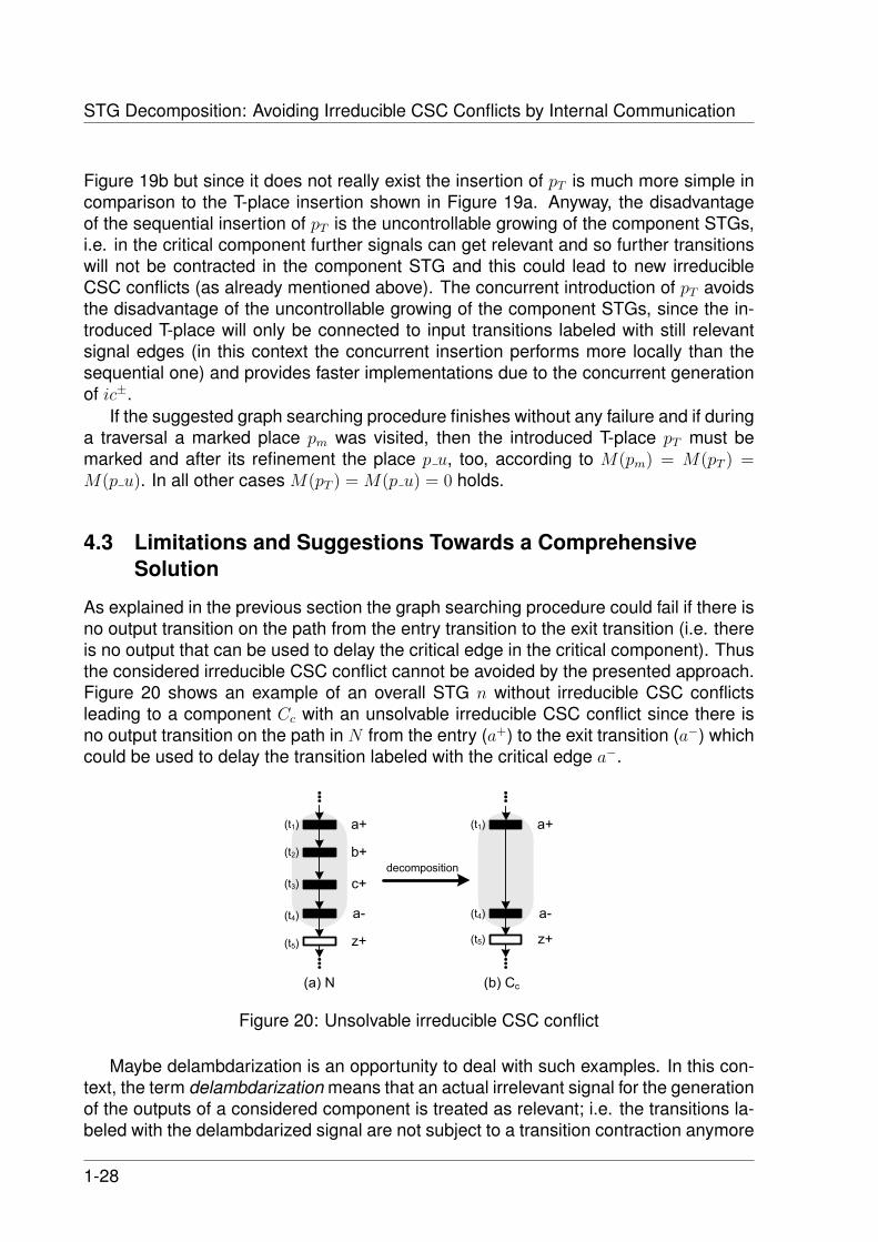
As explained in the previous section the graph searching procedure could fail if there isno output transition on the path from the entry transition to the exit transition (i.e. thereis no output that can be used to delay the critical edge in the critical component). Thusthe considered irreducible CSC conflict cannot be avoided by the presented approach.Figure 20 shows an example of an overall STG n without irreducible CSC conflictsleading to a component Cc with an unsolvable irreducible CSC conflict since there isno output transition on the path in N from the entry (a+) to the exit transition (a−) whichcould be used to delay the transition labeled with the critical edge a−.
a+
b+
c+
a-
z+
a+
a-
z+
decomposition
(a) N (b) Cc
(t1)
(t2)
(t3)
(t4)
(t5)
(t1)
(t4)
(t5)
Figure 20: Unsolvable irreducible CSC conflict
Maybe delambdarization is an opportunity to deal with such examples. In this con-text, the term delambdarization means that an actual irrelevant signal for the generationof the outputs of a considered component is treated as relevant; i.e. the transitions la-beled with the delambdarized signal are not subject to a transition contraction anymore
1-28

4 TOWARDS A STRUCTURAL METHOD
and are reintroduced as input transitions in the resulting component STG. In the ex-ample of Figure 20 signal b could be delambdarized in the critical STG component Cc
leading to an STG component C ′c (resulting from N , by the contraction of transitiont3). In fact, this avoids the considered irreducible CSC conflict, but it may force fur-ther input self-triggers in C ′c; e.g. due to the existence of further transitions (modelingedges of signal b) new critical input traces b+b− are possible. Of course, this is an un-desired side-effect which is called uncontrollable growing of C ′c (and has already beendiscussed in Section 4.2.3 in another context). Another example for delambdarizationis shown in Figure 21c. In order to avoid the input self-trigger a+a− in STGz the signaly is delambdarized. Since the overall STG does not necessarily satisfy CSC (see Fig-ure 21b), new (irreducible) CSC conflicts can arise; observe that STGz has a new CSCconflict characterized by the critical trace a+y+a−y− (see Figure 21c) which is obviouslyirreducible.
a+
y+
a-
y-
z+
Decomposition
with
delamdarization
of y
(b) overall STG (c) STGz
(t1)
(t2)
(t3)
(t4)
(t5)
a+
y+
a-
y-
z+
(t1)
(t2)
(t3)
(t4)
(t5)
a+
y+
a-
y-
z+
(t1)
(t2)
(t3)
(t4)
(t5)
Decomposition
(Out)={...{z,y}...}
(a) STGzy
Figure 21: Delambdarization vs. coarse grained partitioning
Alternatively, signal y could be introduced as an output signal as well in STGzyielding STGzy (Figure 21a). The introduction of y as an output can be realized bya so-called coarse-grained partitioning, i.e. the output partition π(Out) must look like{... {z, y} ...}. This avoids the input self-trigger a+a− in STGzy, too, but due to the gen-eration of the new output y by the critical component, maybe further triggers for all they labeled transitions are needed and thus the set of relevant signals for STGzy maygrow significantly. Moreover, it is possible that a certain output signal is needed toavoid irreducible CSC conflicts in more than one component STG, say in C1 and C2.Since an output can only be generated by one component, the STG components C1
and C2 must form one combined STG component C1,2 which is subject to logic synthe-sis. As a consequence of this coarse-grained partitioning, perhaps only few transitionsare contractable or, at the worst, no decomposition can be applied at all.
Thus the presented introduction of new internal communication signals or transi-tions resp. is more flexible and can be performed more locally with respect to the con-sidered irreducible CSC conflict; i.e. a suitable introduction of ICTs avoids uncontrol-lable growing of the resulting component STGs, since it does not effect any transitionswhich are not related to some considered irreducible CSC conflict.
According to the previous discussion some conclusions will be given with respectto Figure 22 i.e. some considerations towards a comprehensive approach in order todeal with irreducible CSC conflicts.
1-29

STG Decomposition: Avoiding Irreducible CSC Conflicts by Internal Communication
component STGs Ci
SI implementable
with irreducable CSC conflicts
irr. CSC conflicts can
be avoided by
internal communication
not
avoidable
structural decomposer(standard technique)
overall STG N
Figure 22: Classification of component STGs resulting from STG decomposition [26]
Let us assume, we would like to synthesize a complex circuit based on decompo-sition. Then the decomposition [21, 25, 26] could lead to component STGs Ci and onthe one hand side some of them are SI implementable and on the other hand someof them have irreducible CSC conflicts. Hopefully, these irreducible CSC conflicts canoften be solved by the presented approach (i.e. by the introduction of a suitable in-ternal communication among the component STGs). However, if the conflicts of someof the critical STG components are not avoidable by the presented method (in Figure22 these component STGs are represented by the gray filled circle), the application ofdelambdarization as described e.g. in [15] may be a promising alternative. Another op-portunity to deal with such critical STG components is to build larger component STGsby using coarse-grained partitioning as discussed above. Further research will focusthese possibilities.
5 Examples
In this section the suitability of the presented approach will be demonstrated on twoexamples. The first example – a FIFO controller – is a simple textbook example knownfrom literature [3] and the second one is a handshake circuit controller design whichis of more practical relevance since it describes the application of logic synthesis to amodel resulting from an HDL specification (such as a BALSA-program).
5.1 FIFO Controller
This textbook example describes the design of a FIFO stage which can be used as acomponent of an entire FIFO memory realized by a cascade of such FIFO stages [3].Incoming data of the entire FIFO memory will be distributed alternately throughout twoD-register pipelines under the control of the signals RD. In the last FIFO stage a multi-plexer controlled byRM generates the output of the entire FIFO memory (i.e. it restoresthe original order of the data items) and this last FIFO stage will be considered now (see
1-30
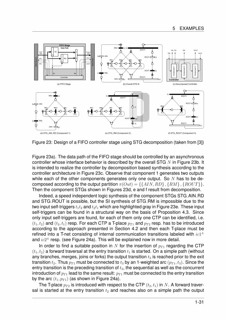
5 EXAMPLES
Controller
FIFO Stage
Data Path
RD+ RM+ RD- RM-
RIN+AOUT+
AIN+ROUT+
ROUT-
AOUT-
RIN-
AIN-
RD+ RM+ RD- RM-
RIN+
AIN+
RIN-
AIN-
RD+ RM+ RD- RM-
AOUT+
AOUT-
p1
p2
RM+ RM-
AOUT+
ROUT+
ROUT-
AOUT-
VD
RD
1
0
Output-
data
Controller
RD RM
Data Source
Data Drain
Input-
data
AIN
RIN AOUT
ROUT
Component 1
Component 2
Component 3
RM ROUTRDAIN
AOUTRIN
(d) STG_AIN_RD (Component 1) (e) STG_RM (Component 2) (f) STG_ROUT (Component 3)
(c) Decomposed Controller (b) Overall STG N(a) FIFO Stage
(t1)
(t2)
(t3)
(t4)
(t5)
(t6)
(t7)
(t8)
(t9) (t10) (t11) (t12)
(t1)
(t2)
(t9) (t10) (t11) (t12)
(t5)
(t6)
(t7)
(t8)
(t9) (t10) (t11) (t12)
(t1)
(t2)
(t3)
(t4)
(t10) (t12)
Figure 23: Design of a FIFO controller stage using STG decomposition (taken from [3])
Figure 23a). The data path of the FIFO stage should be controlled by an asynchronouscontroller whose interface behavior is described by the overall STG N in Figure 23b. Itis intended to realize the controller by decomposition based synthesis according to thecontroller architecture in Figure 23c. Observe that component 1 generates two outputswhile each of the other components generates only one output. So N has to be de-composed according to the output partition π(Out) = {{AIN,RD} , {RM} , {ROUT}}.Then the component STGs shown in Figures 23d, e and f result from decomposition.
Indeed, a speed independent logic synthesis of the component STGs STG AIN RDand STG ROUT is possible, but the SI synthesis of STG RM is impossible due to thetwo input self-triggers t1t2 and t2t1 which are highlighted gray in Figure 23e. These inputself-triggers can be found in a structural way on the basis of Proposition 4.3. Sinceonly input self-triggers are found, for each of them only one CTP can be identified, i.e.(t1, t2) and (t2, t1) resp. For each CTP a T-place pT1 and pT2 resp. has to be introducedaccording to the approach presented in Section 4.2 and then each T-place must berefined into a T-net consisting of internal communication transitions labeled with ic1±
and ic2± resp. (see Figure 24a). This will be explained now in more detail.In order to find a suitable position in N for the insertion of pT1 regarding the CTP
(t1, t2) a forward traversal at the entry transition t1 is started. On a simple path (withoutany branches, merges, joins or forks) the output transition t3 is reached prior to the exittransition t2. Thus pT1 must be connected to t3 by an 1-weighted arc (pT1, t3). Since theentry transition is the preceding transition of t3, the sequential as well as the concurrentintroduction of pT1 lead to the same result: pT1 must be connected to the entry transitionby the arc (t1, pT1) (as shown in Figure 24a).
The T-place pT2 is introduced with respect to the CTP (t2, t1) in N . A forward traver-sal is started at the entry transition t2 and reaches also on a simple path the output
1-31

STG Decomposition: Avoiding Irreducible CSC Conflicts by Internal Communication
pT2
pT1
RD+ RM+ RD- RM-
AOUT+
AOUT-
RM+ RM-
ROUT+
ROUT-ic1+ ic1-
ic2+ ic2-
ic1+ ic1-
ic2+ ic2-
RD+ RM+ RD- RM-
RIN+AOUT+
AIN+
ROUT+
ROUT-
AOUT-
pmRIN-
AIN-
(a) Overall STG N’ extended by internal communication signals
Controller
Component 1
Component 2'
Component 3'
RM ROUTRDAIN
AOUTRIN
(b) Decomposed Controller
ic2
ic1
ic1+ ic1-
p_o
p_u
ic2+ ic2-
(c) STG_RM_ic1_ic2 (Component 2') (d) STG_ROUT’ (Component 3')
(t1)
(t2)
(t3)
(t4)
(t5)
(t6)
(t7)
(t8)
(t9) (t10) (t11) (t12)
(t1)
(t2)(t9) (t10) (t11) (t12)
(t3)
(t4)
(t10) (t12)
(t13) (t14)
(t15) (t16)
(t13) (t14)
(t15) (t16)
(t13) (t14)
(t15) (t16)
pT2
pT1
RD+ RM+ RD- RM-
RIN+AOUT+
AIN+
AOUT-
RIN-
AIN-
(e) STG_AIN_RD’ (Component 1')
ic1+ ic1-
p_o
p_u
ic2+ ic2-
(t1)
(t2)
(t5)
(t6)
(t7)
(t8)
(t9) (t10) (t11) (t12)
(t13) (t14)
(t15) (t16)
Figure 24: Extension of the FIFO controller in order to reach SI implementability
1-32

5 EXAMPLES
transition t4 prior to the exit transition t1. Consequently, the arcs (pT2, t4) and (t2, pT2)are introduced. Since during the traversal a marked place was visited, M(pm) = 1, theT-place pT2 gets one token and thus the place p u has to be marked, i.e. M(p u) = 1.This results in the extended overall STG N ′ (Figure 24a).
Now, the decomposition of N ′ must be applied according to a suitable outputpartition in such a way that the introduced internal communication transitions con-tribute to the avoidance of the considered irreducible CSC conflicts in STG RM,i.e. we need the partition block {RM, ic1, ic2} in π(Out). Since STG AIN RD aswell as STG ROUT were already SI implementable, the partition blocks {AIN,RD}and {ROUT} remain unchanged. So we decompose N ′ according to the partitionπ(Out) = {{RM, ic1, ic2} , {AIN,RD} , {ROUT}} and get the component STGs shownin Figures 24c, d and e. All of these STG components are SI implementable and thusthe entire FIFO controller is.
However, the decomposition does not only lead to a modified STG of the criticalcomponent (STG RM ic1 ic2) and the delay component (STG ROUT’), but it leads alsoto a modified version STG AIN RD’ for component 1 (see Figure 24e), even thoughcomponent 1 is not directly involved in the internal communication for the avoidanceof the considered irreducible CSC conflicts in STG RM. Anyway, this rather complexSTG AIN RD’ arises since the transitions of a T-net cannot be contracted in a securemanner according to [26]. To show this, let us assume the transition labeled with ic− inthe T-net in Figure 11 should be contracted, then a secure contraction of this transitiont is impossible, since neither (
•t)• ⊆ {t} nor •(t•) = {t} holds, i.e. the t-contraction
is neither type-1 secure nor type-2 secure. However, since component 1’ does notcontribute to the delay of the critical edge in component 2, it obviously must be possibleto replace component 1’ by component 1 in the resulting controller implementation (seeFigure 24b).
As you can see in Figure 24b, the implementation has two additional signals ic1 andic2 in comparison with the block diagram in Figure 23c. These additional two signalsact as channels for the introduced one-sided internal communication from component2’ to component 3’.
Of course, the STG component STG ROUT’ (see Figure 24d) is also modified incomparison to STG ROUT (Figure 23f), even though it was already SI implementable.However, such an extension of STG ROUT by T-nets is necessary, since it specifiesthe behavior for the delay component which must realize one part of the introducedone-sided internal communication. Nevertheless, no further irreducible CSC conflictsare expected by such an extension of the delay component STG; of course, this mustbe proved in future work.
Finally, let us consider the complexity of the results shown in Table 1 (Note thatCx y represents an STG component producing the outputs x and y.). The first rowshows the sizes of the reachability graphs of the original overall STG (Figure 23b)and the corresponding component STGs (Figures 23d, e and f). Note that componentSTG RM (see Figure 23e) is not SI implementable. Due to the introduction of the T-nets as presented in this work the component STGs grow at least twice as much insizes of their reachability graphs in comparison to the component STGs without anyextensions for internal communication. In particular STG RM and STG ROUT: they
1-33

STG Decomposition: Avoiding Irreducible CSC Conflicts by Internal Communication
N CAIN RD CRM CROUT
standard technique(without int. comm.)
140 20 16 14
all T-nets 220 160 32 32necessary T-nets 220 20 32 32single transition in-sertion
220 20 32 16
Table 1: Marking counts of the component reachability graphs of the FIFO example
have 16 and 14 markings without any internal communication extensions and with bothT-nets 32 markings. Since the decomposition approach of Vogler et al. so far cannotcontract transitions of a T-net in a secure manner (as already explained) the componentSTG producing AIN and RD has 160 markings instead of 20 markings. Since theoriginal FIFO controller STG in Figure 23b has only 140 markings the 160 markingsare not acceptable and we use instead STG AIN RD from the decomposition of theoriginal overall STG. This must be possible since component 1 does not contribute tothe internal communication that avoids the considered input self-triggers.
In spite of the higher complexity of STG RM ic1 ic2 and STG ROUT’ in comparisonto STG RM and STG ROUT they can be synthesized by PETRIFY and so the presentedapproach is an opportunity to cope with the state explosion problem during logic syn-thesis of complex overall STGs.
With regard to further optimizations, only single internal transitions labeled with ic+
are introduced for the avoidance of a particular input self-trigger instead of introducingan entire T-net. In order to preserve the consistency of the overall STG, the comple-mentary edge ic− is inserted by hand (input proper event insertion) this will be calledthe single transition insertion approach. In fact, this does not lead to a smaller over-all STG but at least to one smaller component STG (CROUT ) with 16 instead of 32markings (see the 4th row in Table 1).
5.2 Sequencer/Parallelizer Tree
The sequencer/parallelizer tree is of more practical relevance, since the design entrypoint is an HDL program (e.g. BALSA or TANGRAM). Then a netlist of so-called hand-shake components (HCs) could be derived by syntax directed translation, see Figure25a. Note that the circles model these handshake components. We can get an (over-all) STG modeling the behavior specified by this HC netlist due to parallel compositionof the single HC STGs. Each HC STG describes the interface behavior of a particu-lar handshake component (as already explained in the introduction). However, sinceonly the overall I/O behavior of the entire control part is of interest for logic synthe-sis, the internal HC communication signals among the handshake components can behidden in the parallel composed overall STG (i.e. their corresponding transitions canbe contracted). In Figure 25a the signals to hide are labeled with λ. Hiding these in-ternal HC communication signals hopefully leads to better hardware implementationscompared to direct mapping techniques. The application of parallel composition to
1-34

5 EXAMPLES
Controller
;
||
seq_0_0_inseq_0_0_out
par_1_0_a_out
par_1_0_a_in
par_1_0_b_out
par_1_0_b_in
||par_1_1_a_out
par_1_1_a_in
par_1_1_b_out
par_1_1_b_in
(a) HC netlist (internal HC communication signalsare labeled with λ)
1
seq_0_0_in+/2
par_1_0_b_out+/4 par_1_0_a_out+/6
par_1_0_b_out-/35
par_1_0_b_in-/32
par_1_1_a_out+/19 par_1_1_b_out+/21
seq_0_0_out-/1
par_1_1_a_in+/15 par_1_1_b_in+/22
par_1_0_b_in+/10 par_1_0_a_in+/8
par_1_0_a_out-/37
par_1_0_a_in-/40
par_1_1_a_out-/12
par_1_1_a_in-/13
seq_0_0_out+/17
seq_0_0_in-/26
par_1_1_b_out-/24
par_1_1_b_in-/29
(b) Overall controller STG (λ-transitions already contracted)
Figure 25: Sequencer/Parallelizer Tree with two levels
1-35

STG Decomposition: Avoiding Irreducible CSC Conflicts by Internal Communication
the HC STGs as well as the hiding of internal HC communication signals on the se-quencer/parallelizer netlist in Figure 25a leads to the overall STG shown in Figure 25b.(Observe that input transitions are drawn in red and output transitions in blue. If youcannot distinguish colors on your print, the signal types in the HC netlist in Figure 25agive also the information whether a transition is an input or an output transition.)
Of course, this example could be expanded to a sequencer/parallelizer tree withmore than two levels. But if it has four or more levels, then PETRIFY cannot synthesizethe corresponding controller STG due to state explosion. Thus STG decomposition isneeded, but with the decomposition according to [21, 25, 26] problems arise similar tothose that arise in the two level sequencer/parallelizer tree and so – for simplicity – weconsider only this smaller example now.
After a total decomposition of the overall STG (i.e. one output signal per STG com-ponent) at least one input self-trigger arises in each component STG (see Figure 26,each transition pair forming an input self-trigger is surrounded by a dashed polygon).The caption at the bottom of each component STG identifies its single output signal i.e.all transitions labeled with an edge of this output signal are output transitions and theall the other transitions are inputs.
Considering all component STGs in Figure 26, via Proposition 4.3 one can identifyall transitions belonging to input self-triggers and, if during the decomposition the tran-sition names are preserved, then the transitions forming the input self-triggers can beidentified in the overall STG.
For all of the eight identified input self-triggers and their corresponding CTPs eightT-places pT1 ... pT8 have to be introduced in the overall STG leading to the extendedoverall STG NT (shown in Figure 27). Then, each of these T-places must be refined bya T-net modeling the internal communication via the signals ic1, ic2, ... or ic8 resp.
Finally, the extended STG NT must be decomposed according to the following suit-able output partition:
π(Out) = {{seq 0 0 out, ic1, ic2}, {par 1 0 b out, ic8}, {par 1 1 a out, ic3, ic4},{par 1 0 a out, ic7}, {par 1 1 b out, ic5, ic6}}
After this, all of the five resulting component STGs can be implemented as speedindependent circuits e.g. by PETRIFY. Figure 28 shows one of these components,namely Cseq 0 0 out. By the way, the index seq 0 0 out represents the output signal whichis produced by this component.
However, the component STGs are rather complex due to the sizes of their reacha-bility graphs, since the contraction of transitions of a T-net is not secure according to thedecomposition of [25,26]; thus each component STG still contains all eight T-nets. Thesecond row of Table 2 shows the marking count of each STG component as the resultof the decomposition [25, 26]. Indeed, these component STGs are SI implementablenow, but their reachability graphs are up to a factor of 15 larger than the reachabilitygraphs resulting from a standard decomposition of the STG shown in Figure 25b.
Regarding Cseq 0 0 out in Figure 28 the signals ic3, ic4, ic5 and ic6 are actually notrelevant, but the provided decomposition approach cannot accomplish the contractionof the corresponding transitions. So in future work the contraction of entire STG parts,such as an entire T-Net structure, will be investigated. In this context, it is proposed
1-36

5 EXAMPLES
1
seq_0_0_in+/5
par_1_1_a_in+/7 par_1_1_b_in+/9
seq_0_0_out+/1
seq_0_0_in-/2
seq_0_0_out-/4
par_1_1_a_in-/15 par_1_1_b_in-/11
(a) seq 0 0 out
1
seq_0_0_in+/1
par_1_0_a_out+/2
par_1_0_a_in+/4
par_1_0_a_out-/6
par_1_0_a_in-/7
seq_0_0_in-/10
(b) par 1 0 a out
1
seq_0_0_in+/4
par_1_0_b_out+/5
par_1_0_b_out-/1
par_1_0_b_in-/2
seq_0_0_in-/7
par_1_0_b_in+/9
(c) par 1 0 b out
1
par_1_0_a_in+/6
par_1_0_a_in-/7
1
par_1_0_b_in+/9
par_1_0_b_in-/4
par_1_1_a_out+/1
par_1_1_a_in+/2
par_1_1_a_out-/12
par_1_1_a_in-/13
(d) par 1 1 a out
1
par_1_0_a_in+/8
par_1_0_a_in-/9
1
par_1_0_b_in+/13
par_1_0_b_in-/1
par_1_1_b_out+/2
par_1_1_b_in+/4
par_1_1_b_out-/6
par_1_1_b_in-/11
(e) par 1 1 b out
Figure 26: Decomposition results of the STG in Figure 25b (standard technique)
1-37

STG Decomposition: Avoiding Irreducible CSC Conflicts by Internal Communication
1
seq_0_0_in+/2
par_1_0_b_out+/4par_1_0_a_out+/6
ic1+/40
ic1-/41
1
par_1_1_a_out-/12
par_1_1_a_in-/13
ic2+/46
ic2-/47
1
ic3-/53
ic3+/52
1
par_1_1_b_out-/25
par_1_1_b_in-/26
par_1_0_b_out-/32
par_1_0_b_in-/29
ic4-/59
ic4+/58
1
ic5+/64
ic5-/65
1
par_1_0_a_out-/37
par_1_0_a_in-/34
ic6+/70
ic6-/71
1
seq_0_0_out-/1
ic7+/76
ic7-/77
1 1
ic8+/82
ic8-/83
par_1_0_b_in+/10par_1_0_a_in+/8
seq_0_0_out+/15
seq_0_0_in-/23
par_1_1_a_out+/17
par_1_1_a_in+/18par_1_1_b_in+/21
par_1_1_b_out+/20
pT3 pT4 pT5 pT3
pT2 pT1
pT7 pT8
Figure 27: Overall STG NT as an extension of N in Figure 25b modeling internal commu-nication of the resulting component STGs by the outputs ic1...ic8 (to avoid irreducible CSCconflicts)
1-38

5 EXAMPLES
par_1_0_b_out-/2
par_1_1_a_in+/50
par_1_1_b_in+/51
seq_0_0_out-/4
1 1
1
ic4+/23
ic4-/22
par_1_0_a_out-/6
par_1_1_a_in-/9
seq_0_0_out+/48
ic5+/11
ic5-/12
1
ic6+/14
ic6-/15
1
par_1_1_b_in-/17
ic3-/19
ic3+/20
1
ic8-/25
ic8+/26
1
ic1-/29
ic1+/28
1
ic7-/32
ic7+/31
1
ic2+/34
ic2-/35
1
par_1_0_a_out+/38 par_1_0_b_out+/40
Figure 28: Component STG Cseq 0 0 out resulting from the decomposition of NT (in Fig. 27)
1-39

STG Decomposition: Avoiding Irreducible CSC Conflicts by Internal Communication
N Cseq 0 0 out Cpar 1 0 a out Cpar 1 0 b out Cpar 1 1 a out Cpar 1 1 b out
standardtechnique(w/o int.comm.)
52 12 6 6 12 12
all T-nets 210 110 90 90 94 94necessaryT-nets
210 40 16 16 36 36
single tran-sition inser-tion
134 21 8 14 21 42
Table 2: Marking counts of the components for the two-level sequencer/parallelizer tree
to ‘re-refine’ each T-net consisting of the transitions of an irrelevant signal by a T-placeagain, as outlined by the dashed circles in Figure 28. Then the standard decompositiontechnique even detects the signals par 1 0 a out and par 1 0 b out as irrelevant (andtherefore the transitions labeled with these signals are crossed out in Figure 28). Thusthe decomposition finally would lead to the reduced component STG C ′seq 0 0 out whichis shown in Figure 29.
With this treatment of such T-net contraction in mind, for all component STGs re-sulting from the decomposition of NT the component sizes and their marking countsare significantly smaller (cf. the second and the third row in Table 2). In fact, thesemarking counts are still larger than the amounts of markings of the STG componentswithout any extensions for internal communication, but this enlargement averages to afactor of 3 instead a factor of 15. Note that the original overall STG (see Figure 25b)has 52 markings and no CSC while the component STGs containing only the neces-sary T-nets are all smaller and do satisfy already CSC, so they are more suitable to aPETRIFY synthesis in contrast to the original overall STG.
With regard to further optimizations, the single transition insertion approach leads toan overall STG which is much smaller (134 markings) as the overall STG containing theeight T-nets (210 marking). Moreover, its decomposition results are smaller than thosecontaining the necessary T-nets except for the component generating output signalpar 1 1 b out (cf. 3rd and 4th row of Table 2).
1-40

5 EXAMPLES
1
ic8+/30
ic8-/31
seq_0_0_out-/1
1 1
par_1_1_a_in+/2 par_1_1_b_in+/4
ic1+/12
ic1-/13
1
par_1_1_a_in-/9
seq_0_0_out+/7
ic2-/19
ic2+/18
1
par_1_1_b_in-/6
ic7-/25
ic7+/24
1
Figure 29: Component STG C ′seq 0 0 out
1-41

STG Decomposition: Avoiding Irreducible CSC Conflicts by Internal Communication
6 Conclusions and Future Work
The presented idea may be an important step in asynchronous system design basedon STG decomposition [21, 25, 26] and SI logic synthesis. Irreducible CSC conflicts incomponent STGs are avoidable by the introduction of internal communication amongthe STG components; this enables the SI logic synthesis in many cases and thus itcontributes to the preprocessing problem (see also Figure 1).
Moreover, considerations towards an algorithmic structural solution for the introduc-tion of internal communication are presented. Indeed, some restrictions on the netclass must be accepted (see Section 4.3), but our approach seems to be useful inmany practical cases. First promising results were presented in Section 5. However, acorrectness proof for the presented method is still missing.
In future work, the approach explained in Section 4 has to be completed, yieldinga 2-cycle algorithm that will be implemented and integrated in our decomposition toolDESIJ3. The two cycles are characterized as follows:
1. Find all irreducible CSC conflicts in the STG components and identify all transi-tions of the corresponding critical transition sequences in the overall STG.
2. Avoid the irreducible CSC conflicts by the introduction of internal communicationtransitions in the overall STG (according to the methods presented in Section 3and 4) and a new decomposition with a suitable output partition.
So far especially input self-triggers are considered and in further research the han-dling of general CSC conflicts will be investigated in more detail. For that, we areaiming at the efficient extraction of a single CTP or at least a minimal set of CTPs fromall CTSs belonging to a particular irreducible CSC conflict; then these extracted CTPsmight be split by a single T-place and thus by a single T-net. Consequently, it is nec-essary to get all CTSs belonging to a certain irreducible CSC conflict at once and notonly one instance of them as the tool PETRIFY does; maybe, the tool MPSAT providesan opportunity in order to deal with this problem.
Furthermore, the influence of the T-net introduction in the delay component bymeans of its SI implementability has to be investigated. Hopefully, it can be provedthat it does not affect the SI implementability of the delay component, i.e. it should beproved that if a component STG producing some output x can be implemented as anSI circuit before the introduction of some internal communication transition, then it isstill SI implementable after its introduction. In this context, also the side-effects of theT-net introduction with respect to STG components that are not involved in the internalcommunication (to avoid a particular irreducible CSC conflict) have to be investigated.
So far the decomposition of [21, 25, 26] cannot contract the transitions of a T-net ina secure manner. Thus the extension of the decomposition approach concerning thesecure contraction of entire STG parts (such as entire T-nets) has to be investigated.
A different way to avoid this problem and to reduce the complexity of the resultingSTGs is to replace the T-net insertion w.r.t. an internal signal ic by the insertion of a
3 http://www.informatik.uni-augsburg.de/en/chairs/swt/ti/research/tools/desij
1-42

6 CONCLUSIONS AND FUTURE WORK
single internal transition labeled with one edge of ic only. (Of course we then have toinsert the complementary transition at a different position in N in a consistent way.)This could lead to reachability graphs with significantly reduced sizes in comparisonto the T-net introduction, as shown in the result tables in Section 5. Maybe the workpresented in [14,18] will give some suggestions for this improved transition insertion.
For STG components whose irreducible CSC conflicts are not avoidable by the pre-sented method, the systematic reintroduction of irrelevant signals may help – or, in thecase of overall STGs extracted from an HC netlist (resulting from a parallel compositionof HC STGs with hidden internal HC communication signals) the reintroduction of thesehidden signals could be successful. On the one hand these actual irrelevant signalscan be reintroduced in the critical component STG as inputs (‘delambdarization’) or, onthe other hand, as outputs (coarse-grained partitioning) – but both methods may leadto uncontrollable growing (see Section 4.3).
AcknowledgmentsThis research was supported by the DFG-project ‘STG-Dekomposition’ Wo814/1-3.We would like to thank Mark Schafer for the helpful cooperation.
1-43

STG Decomposition: Avoiding Irreducible CSC Conflicts by Internal Communication
References[1] Andrew Bardsley. Implementing Balsa Handshake Circuits. PhD thesis, University of
Manchester, Faculty of Science and Engineering, School of Computer Science, 2000.
[2] Andrew Bardsley and Doug Edwards. Compiling the language Balsa to delay insensitivehardware. In CHDL’97: Proceedings of the IFIP TC10 WG10.5 international conference onHardware description languages and their applications : specification, modelling, verifica-tion and synthesis of microelectronic systems, pages 89–91, London, UK, 1997. Chapman& Hall, Ltd.
[3] Jochen Beister and Ralf Wollowski. Controller implementation by communicating asyn-chronous sequential circuits generated from a Petri net specification of required behavior.In Synthesis for Control Dominated Circuits, pages 103–115, 1992.
[4] Gerard Berthelot. Transformations and decompositions of nets. In Proceedings of anAdvanced Course on Petri Nets: Central Models and Their Properties, Advances in PetriNets 1986-Part I, pages 359–376, London, UK, 1987. Springer-Verlag.
[5] Josep Carmona and Jordi Cortadella. ILP models for the synthesis of asynchronous con-trol circuits. In ICCAD ’03: Proceedings of the 2003 IEEE/ACM international conferenceon Computer-aided design, Washington, DC, USA, 2003.
[6] Tiberiu Chelcea and Steven M. Nowick. Resynthesis and peephole transformations for theoptimization of large-scale asynchronous systems. In DAC ’02: Proceedings of the 39thconference on Design automation, pages 405–410, New York, USA, 2002.
[7] T.-A. Chu. Synthesis of Self-Timed VLSI Circuits from Graph-Theoretic Specifications.PhD thesis, Massachusetts Institute of Technology, 1987.
[8] J. Cortadella, M. Kishinevsky, A. Kondratyev, L. Lavagno, and A. Yakovlev. Petrify: a tool formanipulating concurrent specifications and synthesis of asynchronous controllers. IEICETransactions on Information and Systems, E80-D(3):315–325, 1997.
[9] J. Cortadella, M. Kishinevsky, A. Kondratyev, L. Lavagno, and A. Yakovlev. Logic synthesisof asynchronous controllers and interfaces. Springer-Verlag, ISBN: 3-540-43152-7, 2002.
[10] Jo C. Ebergen. Arbiters: an exercise in specifying and decomposing asynchronouslycommunicating components. Sci. Comput. Program., 18(3):223–245, 1992.
[11] N. Karaki, T. Nanmoto, H. Ebihara, S. Utsunomiya, S. Inoue, and T. Shimoda. A flexible8b asynchronous microprocessor based on low-temperature poly-silicon TFT technology.In ISSCC ’05: Proceedings of the Solid-State Circuits Conference, 2005, pages 272–598.Seiko Epson Corp., Nagano, Japan, 2005.
[12] Victor Khomenko, Maciej Koutny, and Alex Yakovlev. Detecting state coding conflicts inSTG unfoldings using SAT. In Third International Conference on Application of Concur-rency to System Design (ACSD’03), Guimares, Portugal, pages 51–60, June 2003.
[13] Victor Khomenko, Maciej Koutny, and Alex Yakovlev. Logic synthesis for asynchronouscircuits based on Petri net unfoldings and incremental SAT. In Proceedings of FourthInternational Conference on Application of Concurrency to System Design (ACSD’04),June 16 - 18, 2004, Hamilton, Ontario, Canada, pages 16–25, June 2004.
1-44

REFERENCES
[14] Victor Khomenko, Agnes Madalinski, and Alex Yakovlev. Resolution of encoding conflictsby signal insertion and concurrency reduction based on STG unfoldings. In ACSD ’06:Proceedings of the Sixth International Conference on Application of Concurrency to Sys-tem Design, pages 57–68, Washington, DC, USA, 2006.
[15] Victor Khomenko and Mark Schafer. Combining decomposition and unfolding for STGsynthesis. In ICATPN ’07: 28th International Conference on Applications and Theory ofPetri Nets and Other Models of Concurrency, pages 223–243, 2007.
[16] Victor Khomenko, Mark Schafer, and Walter Vogler. Output-determinacy and asyn-chronous circuit synthesis. In ACSD ’07: Seventh International Conference on Applicationof Concurrency to System Design, pages 147–156, 2007.
[17] A. Kondratyev, M. Kishinevsky, and A. Taubin. Synthesis method in self-timed design.Decompositional approach. In Proc. ICVC’93, pages 324–327, 1993.
[18] Agnes Madalinski, Alex Bystrov, Victor Khomenko, and Alex Yakovlev. Visualization andresolution of coding conflicts in asynchronous circuit design. In DATE ’03: Proceedings ofthe Conference on Design, Automation and Test in Europe, Washington, DC, USA, 2003.
[19] Steven Mark Nowick. Automatic Synthesis of Burst-mode Asynchronous Controllers. PhDthesis, Computer Systems Laboratory Departments of Electrical Engineering and Com-puter Science at the Stanford University, 1993.
[20] Mark Schaefer and Walter Vogler. Component refinement and CSC solving for STG de-composition. In Vladimiro Sassone, editor, Foundations of Software Science and Compu-tational Structures: 8th International Conference, FOSSACS 2005, volume 3441 of LNCS,pages 348–363. Springer-Verlag, 2005.
[21] Mark Schaefer, Walter Vogler, Ralf Wollowski, and Victor Khomenko. Strategies for op-timised STG decomposition. In ACSD ’06: Proceedings of the Sixth International Con-ference on Application of Concurrency to System Design, pages 123–132, Washington(D.C.), USA, 2006.
[22] Stephen H. Unger. Asynchronous Sequential Switching Circuits. Wiley-Interscience, NewYork, USA, 1969.
[23] Kees van Berkel, Joep Kessels, Marly Roncken, Ronald Saeijs, and Frits Schalij. TheVLSI-programming language Tangram and its translation into handshake circuits. InEURO-DAC ’91: Proceedings of the conference on European design automation, pages384–389, Los Alamitos, CA, USA, 1991.
[24] Hans van Gageldonk, Kees van Berkel, Ad Peeters, Daniel Baumann, Daniel Gloor, andGerhard Stegmann. An asynchronous low-power 80c51 microcontroller. In ASYNC ’98:Proceedings of the 4th International Symposium on Advanced Research in AsynchronousCircuits and Systems, pages 96–107, Washington, DC, USA, 1998.
[25] W. Vogler and B. Kangsah. Improved decomposition of STGs. In ACSD ’05: Proceedingsof the Fifth International Conference on Application of Concurrency to System Design,pages 244–253, Washington, DC, USA, 2005.
1-45

STG Decomposition: Avoiding Irreducible CSC Conflicts by Internal Communication
[26] Walter Vogler and Ralf Wollowski. Decomposition in asynchronous circuit design. Con-currency and Hardware Design — Advances in Petri Nets, Volume 2549 of Lecture Notesin Computer Science / J. Cortadella, A. Yakovlev, G. Rozenberg (Eds.), 2549:152–190,November 2002.
[27] R. Wollowski and J. Beister. Comprehensive causal specification of asynchronous con-troller and arbiter behaviour. In A. Yakovlev, L. Gomes, and L. Lavagno, editors, HardwareDesign and Petri Nets, pages 3–32. Kluwer Academic Publishers, 2000.
[28] T. Yoneda, A. Matsumoto, M. Kato, and C. Myers. High level synthesis of timed asyn-chronous circuits. In Proceedings of the 11th International Symposium on AsynchronousCircuits and Systems, 2005.
[29] Tomohiro Yoneda, Hiroomi Onda, and Chris Myers. Synthesis of speed independent cir-cuits based on decomposition. In In ASYNC’04: 10th IEEE International Symposium onAsynchronous Circuits and Systems, pages 135–145, Los Alamitos, CA, USA, 2004.
[30] K.Y Yun and D.L. Dill. Automatic synthesis of extended burst-mode circuits. II.(automaticsynthesis). In Proceedings of the IEEE Transactions on Computer-Aided Design of Inte-grated Circuits and Systems, volume 18, pages 118–132, 1999.
[31] K.Y Yun and D.L. Dill. Automatic synthesis of extended burst-mode circuits. I.(specificationand hazard-free implementations). In Proceedings of the IEEE Transactions on Computer-Aided Design of Integrated Circuits and Systems, volume 18, pages 101–117, 1999.
1-46

Aktuelle Technische Berichte des Hasso-Plattner-Instituts
Band ISBN Titel Autoren / Redaktion
19
978-3-939469-95-7
A quantitative evaluation of the enhanced Topic-based Vector Space Model
Dominic Wist, Ralf Wollowski
18
978-939-469-58-2
Proceedings of the Fall 2006 Workshop of the HPI Research School on Service-Oriented Systems Engineering
Benjamin Hagedorn, Michael Schöbel, Matthias Uflacker, Flavius Copaciu, Nikola Milanovic
17
3-939469-52-1 / 978-939469-52-
0
Visualizing Movement Dynamics in Virtual Urban Environments
Marc Nienhaus, Bruce Gooch, Jürgen Döllner
16
3-939469-35-1 / 978-3-939469-
35-3
Fundamentals of Service-Oriented Engineering
Andreas Polze, Stefan Hüttenrauch, Uwe Kylau, Martin Grund, Tobias Queck, Anna Ploskonos, Torben Schreiter, Martin Breest, Sören Haubrock, Paul Bouché
15
3-939469-34-3 / 978-3-
939469-34-6
Concepts and Technology of SAP Web Application Server and Service Oriented Architecture Products
Bernhard Gröne, Peter Tabeling, Konrad Hübner
14
3-939469-23-8 / 978-3-939469-
23-0
Aspektorientierte Programmierung – Überblick über Techniken und Werkzeuge
Janin Jeske, Bastian Brehmer, Falko Menge, Stefan Hüttenrauch, Christian Adam, Benjamin Schüler, Wolfgang Schult, Andreas Rasche, Andreas Polze
13
3-939469-13-0 / 978-3-939469-
13-1
A Virtual Machine Architecture for Creating IT-Security Labs
Ji Hu, Dirk Cordel, Christoph Meinel
12
3-937786-89-9 / 978-3-937786-
89-6
An e-Librarian Service - Natural Language Interface for an Efficient Semantic Search within Multimedia Resources
Serge Linckels, Christoph Meinel
11
3-937786-81-3
Requirements for Service Composition
Prof. Dr. M. Weske, Dominik Kuropka Harald Meyer
10
3-937786-78-3
Survey on Service Composition
Prof. Dr. M. Weske, Dominik Kuropka Harald Meyer
9
3-937786-73-2
Sichere Ausführung nicht vertrauenswürdiger Programme
Andreas Polze Johannes Nicolai, Andreas Rasche
8
3-937786-72-4
Resourcenpartitionierung für Grid-Systeme
Andreas Polze, Matthias Lendholt, Peter Tröger
7
3-937786-56-2
Visualizing Design and Spatial Assembly of Interactive CSG
Prof. Dr. Jürgen Döllner, Florian Kirsch, Marc Nienhaus


ISBN 978-3-940793-02-7 ISSN 1613-5652