Stereo Image Coding with Histogram-Pair Based …grxuan.org/httpdocs/english/(IWDW2014)Stereo Image...
15
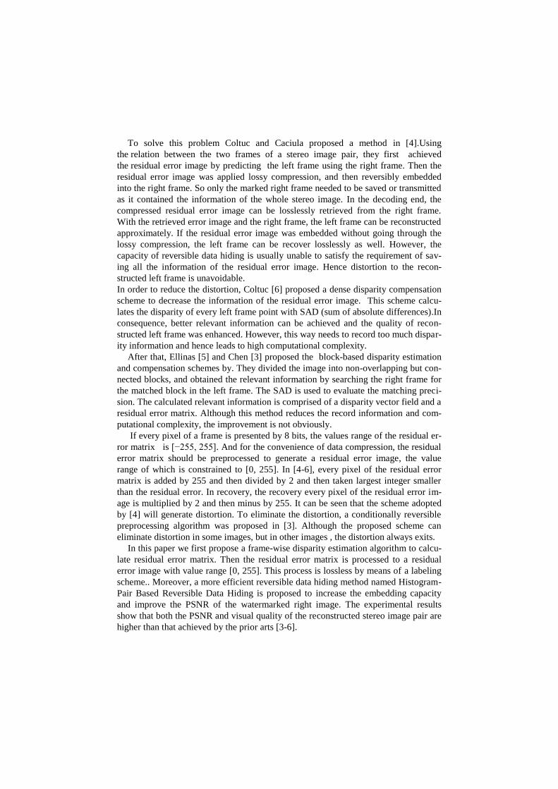
1 This research is largely supported by Shanghai City Board of education scientific research innovation projects (12ZZ033) and National Natural Science Foundation of China (NSFC) on project (90304017). Stereo Image Coding with Histogram-Pair Based Reversible Data Hiding 1 Xuefeng Tong 1 , Guangce Shen 1 , Guorong Xuan 1 , Shumeng Li 1 , Zhiqiang Yang 1 , Jian Li 3 , Yun Q. Shi 2 1 Dept of Computer Science, Tongji University, Shanghai, China 2 ECE, New Jersey Institute of Technology, Newark, New Jersey, USA 3 College of Computer Science and Technology, Nanjing University of Information Science & Technology Guangce Shen <[email protected]> Abstract. This paper presents a stereo image coding method using reversible data hiding technique so that the right frame can be recovered losslessly and the left frame can be reconstructed with high visual quality. Utilizing the similarity between two frames in a stereo image pair the required size of storage and transmission bandwidth for the stereo image pair can be reduced to 50%. A re- sidual error matrix with a dynamic range of [-255,255] is obtained by applying a frame-wise disparity algorithm which first shifts the left frame horizontally by a certain amount and then computes its difference to the right frame. Next, thus generated residual error image with gray levels [0,255] is obtained losslessly by a proposed labeling scheme. JPEG2000 lossy compression is then applied to the residual error image. The histogram-pair based reversible data hiding scheme is then utilized to embed the JPEG2000 lossy compressed data into the right frame. Compared with the prior art, which uses a block-based disparity estima- tion algorithm and a location map based reversible data hiding, the proposed method have demonstrated that the stereo image can be reconstructed with higher visual quality and faster processing speed. Specifically, the experiments have demonstrated that both the PSNR and visual quality of the reconstructed stereo image pair are higher than that achieved by the prior arts. Keywords: Stereo image coding, Histogram-pair based image reversible data hiding, frame-wise algorithm, labeling scheme, 1 Introduction With the rapid development of information technology, especially unprecedented computing capacity, stereo vision technology has made considerable progress and been applied widely in the fields like 3d TV etc. More and more vivid visual experi- ences are brought to people. But one stereo image pair is composed of two 2-D simi- lar images, its storage space and transmission bandwidth required may be twice larger than the traditional image applications. So it is important to develop efficient stereo image coding techniques to decrease its cost on the storage and transmission.
Transcript of Stereo Image Coding with Histogram-Pair Based …grxuan.org/httpdocs/english/(IWDW2014)Stereo Image...
1 This research is largely supported by Shanghai City Board of education scientific research innovation projects (12ZZ033) and
National Natural Science Foundation of China (NSFC) on project (90304017).
Stereo Image Coding with Histogram-Pair Based
Reversible Data Hiding1
Xuefeng Tong1, Guangce Shen
1, Guorong Xuan
1, Shumeng Li
1, Zhiqiang Yang
1,
Jian Li3, Yun Q. Shi
2
1Dept of Computer Science, Tongji University, Shanghai, China 2ECE, New Jersey Institute of Technology, Newark, New Jersey, USA
3College of Computer Science and Technology, Nanjing University of Information Science &
Technology
Guangce Shen <[email protected]>
Abstract. This paper presents a stereo image coding method using reversible
data hiding technique so that the right frame can be recovered losslessly and the
left frame can be reconstructed with high visual quality. Utilizing the similarity
between two frames in a stereo image pair the required size of storage and
transmission bandwidth for the stereo image pair can be reduced to 50%. A re-
sidual error matrix with a dynamic range of [-255,255] is obtained by applying
a frame-wise disparity algorithm which first shifts the left frame horizontally by
a certain amount and then computes its difference to the right frame. Next, thus
generated residual error image with gray levels [0,255] is obtained losslessly by
a proposed labeling scheme. JPEG2000 lossy compression is then applied to the
residual error image. The histogram-pair based reversible data hiding scheme is
then utilized to embed the JPEG2000 lossy compressed data into the right
frame. Compared with the prior art, which uses a block-based disparity estima-
tion algorithm and a location map based reversible data hiding, the proposed
method have demonstrated that the stereo image can be reconstructed with
higher visual quality and faster processing speed. Specifically, the experiments
have demonstrated that both the PSNR and visual quality of the reconstructed
stereo image pair are higher than that achieved by the prior arts.
Keywords: Stereo image coding, Histogram-pair based image reversible data
hiding, frame-wise algorithm, labeling scheme,
1 Introduction
With the rapid development of information technology, especially unprecedented
computing capacity, stereo vision technology has made considerable progress and
been applied widely in the fields like 3d TV etc. More and more vivid visual experi-
ences are brought to people. But one stereo image pair is composed of two 2-D simi-
lar images, its storage space and transmission bandwidth required may be twice larger
than the traditional image applications. So it is important to develop efficient stereo
image coding techniques to decrease its cost on the storage and transmission.
To solve this problem Coltuc and Caciula proposed a method in [4].Using
the relation between the two frames of a stereo image pair, they first achieved
the residual error image by predicting the left frame using the right frame. Then the
residual error image was applied lossy compression, and then reversibly embedded
into the right frame. So only the marked right frame needed to be saved or transmitted
as it contained the information of the whole stereo image. In the decoding end, the
compressed residual error image can be losslessly retrieved from the right frame.
With the retrieved error image and the right frame, the left frame can be reconstructed
approximately. If the residual error image was embedded without going through the
lossy compression, the left frame can be recover losslessly as well. However, the
capacity of reversible data hiding is usually unable to satisfy the requirement of sav-
ing all the information of the residual error image. Hence distortion to the recon-
structed left frame is unavoidable.
In order to reduce the distortion, Coltuc [6] proposed a dense disparity compensation
scheme to decrease the information of the residual error image. This scheme calcu-
lates the disparity of every left frame point with SAD (sum of absolute differences).In
consequence, better relevant information can be achieved and the quality of recon-
structed left frame was enhanced. However, this way needs to record too much dispar-
ity information and hence leads to high computational complexity.
After that, Ellinas [5] and Chen [3] proposed the block-based disparity estimation
and compensation schemes by. They divided the image into non-overlapping but con-
nected blocks, and obtained the relevant information by searching the right frame for
the matched block in the left frame. The SAD is used to evaluate the matching preci-
sion. The calculated relevant information is comprised of a disparity vector field and a
residual error matrix. Although this method reduces the record information and com-
putational complexity, the improvement is not obviously.
If every pixel of a frame is presented by 8 bits, the values range of the residual er-
ror matrix is [−255, 255]. And for the convenience of data compression, the residual
error matrix should be preprocessed to generate a residual error image, the value
range of which is constrained to [0, 255]. In [4-6], every pixel of the residual error
matrix is added by 255 and then divided by 2 and then taken largest integer smaller
than the residual error. In recovery, the recovery every pixel of the residual error im-
age is multiplied by 2 and then minus by 255. It can be seen that the scheme adopted
by [4] will generate distortion. To eliminate the distortion, a conditionally reversible
preprocessing algorithm was proposed in [3]. Although the proposed scheme can
eliminate distortion in some images, but in other images , the distortion always exits.
In this paper we first propose a frame-wise disparity estimation algorithm to calcu-
late residual error matrix. Then the residual error matrix is processed to a residual
error image with value range [0, 255]. This process is lossless by means of a labeling
scheme.. Moreover, a more efficient reversible data hiding method named Histogram-
Pair Based Reversible Data Hiding is proposed to increase the embedding capacity
and improve the PSNR of the watermarked right image. The experimental results
show that both the PSNR and visual quality of the reconstructed stereo image pair are
higher than that achieved by the prior arts [3-6].
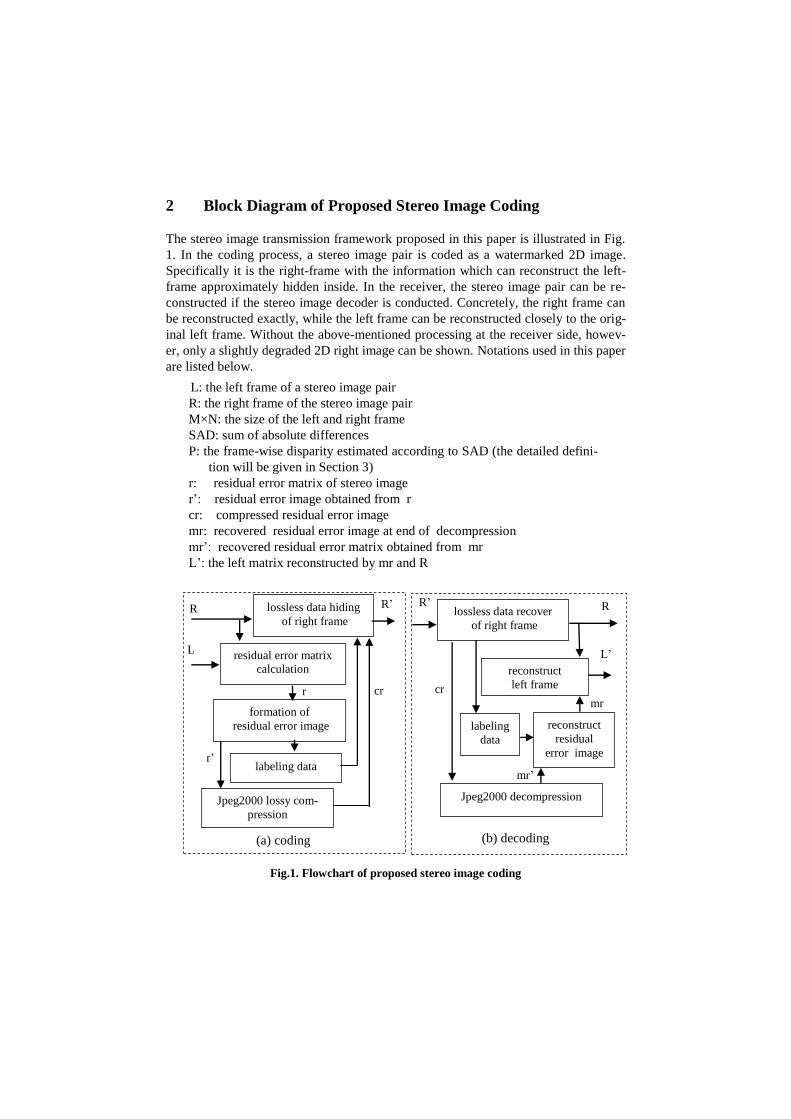
2 Block Diagram of Proposed Stereo Image Coding
The stereo image transmission framework proposed in this paper is illustrated in Fig.
1. In the coding process, a stereo image pair is coded as a watermarked 2D image.
Specifically it is the right-frame with the information which can reconstruct the left-
frame approximately hidden inside. In the receiver, the stereo image pair can be re-
constructed if the stereo image decoder is conducted. Concretely, the right frame can
be reconstructed exactly, while the left frame can be reconstructed closely to the orig-
inal left frame. Without the above-mentioned processing at the receiver side, howev-
er, only a slightly degraded 2D right image can be shown. Notations used in this paper
are listed below.
Fig.1. Flowchart of proposed stereo image coding
L: the left frame of a stereo image pair
R: the right frame of the stereo image pair
M×N: the size of the left and right frame
SAD: sum of absolute differences
P: the frame-wise disparity estimated according to SAD (the detailed defini-
tion will be given in Section 3)
r: residual error matrix of stereo image
r’: residual error image obtained from r
cr: compressed residual error image
mr: recovered residual error image at end of decompression
mr’: recovered residual error matrix obtained from mr
L’: the left matrix reconstructed by mr and R
R
residual error matrix
calculation
formation of
residual error image
lossless data recover
of right frame
R’
labeling
data
reconstruct
left frame
L
R’
L’
labeling data
reconstruct
residual
error image
Jpeg2000 lossy com-
pression
Jpeg2000 decompression
R
(b) decoding (a) coding
lossless data hiding
of right frame
r’
r mr
cr cr
mr’
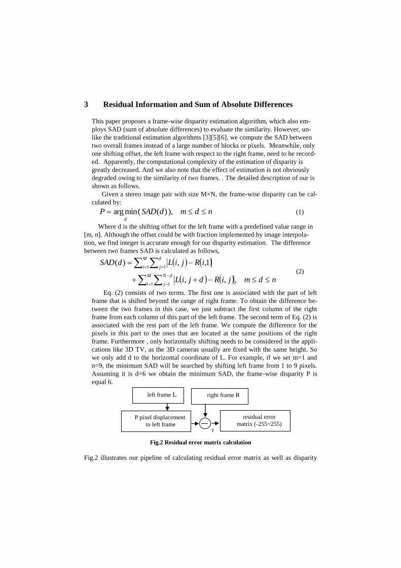
3 Residual Information and Sum of Absolute Differences
This paper proposes a frame-wise disparity estimation algorithm, which also em-
ploys SAD (sum of absolute differences) to evaluate the similarity. However, un-
like the traditional estimation algorithms [3][5][6], we compute the SAD between
two overall frames instead of a large number of blocks or pixels. Meanwhile, only
one shifting offset, the left frame with respect to the right frame, need to be record-
ed. Apparently, the computational complexity of the estimation of disparity is
greatly decreased. And we also note that the effect of estimation is not obviously
degraded owing to the similarity of two frames. . The detailed description of our is
shown as follows.
Given a stereo image pair with size M×N, the frame-wise disparity can be cal-
culated by:
ndmdSADPd
),)((minarg (1)
Where d is the shifting offset for the left frame with a predefined value range in
[m, n]. Although the offset could be with fraction implemented by image interpola-
tion, we find integer is accurate enough for our disparity estimation. The difference
between two frames SAD is calculated as follows,
ndmjiRdjiL
iRjiLdSAD
M
i
dN
j
M
i
d
j
,,,
1,,)(
1 1
1 1 (2)
Eq. (2) consists of two terms. The first one is associated with the part of left
frame that is shifted beyond the range of right frame. To obtain the difference be-
tween the two frames in this case, we just subtract the first column of the right
frame from each column of this part of the left frame. The second term of Eq. (2) is
associated with the rest part of the left frame. We compute the difference for the
pixels in this part to the ones that are located at the same positions of the right
frame. Furthermore , only horizontally shifting needs to be considered in the appli-
cations like 3D TV, as the 3D cameras usually are fixed with the same height. So
we only add d to the horizontal coordinate of L. For example, if we set m=1 and
n=9, the minimum SAD will be searched by shifting left frame from 1 to 9 pixels.
Assuming it is d=6 we obtain the minimum SAD, the frame-wise disparity P is
equal 6.
Fig.2 Residual error matrix calculation
Fig.2 illustrates our pipeline of calculating residual error matrix as well as disparity
left frame L right frame R
P pixel displacement
to left frame residual error
matrix (-255~255) r
estimation. After the frame-wise disparity P has been calculated, the residual error
matrix can be calculated by Eq. (3):
PjMiiRjiL
PNjMijiRPjiLjir
1,1,1,,
1,1,,,, (3)
We note again that in left frame the columns which are shifted beyond the right
frame (i.e., the column number is smaller than P) should be corresponding to the first
column of the right frame. Similarly, the procedure of reconstruction of the left frame
L’ in the decoder end is also performed with two different manners, namely:
PjMiiRjimr
PNjMijiRPjimrjiL
1,1,1,,
1,1,,,,' (4)
Where mr is the residual error matrix recovered at the decoding end. Because of
JPEG2000 lossy compression performed in the coding end (introduced in the next
section), mr is not completely same to r. So if there are pixels in L’ beyond the normal
value range [0, 255], we just round off them to 0 or 255.
4 Residual error image and labeling scheme
For a stereo image presented on 8 bits, the values in the residual error matrix r ob-
tained by Eq. (3) lie in [−255, 255]. For the convenience of data compression, r
should be preprocessed to generate a grayscale residual error image denoted by r′
whose pixel values are constrained to [0, 255].The scheme adopted by [4] [5] [6] are
all irreversible and adopted in [3] also generate distortion in some images. To elimi-
nate distortion, labeling scheme was proposed in this paper. According to our experi-
mental results on many stereo image pairs downloaded from
http://vision.middlebury.edu/stereo, we find most points of a residual error matrix are
in the range of [-127,127]. So we generate residual error image by shrinking the his-
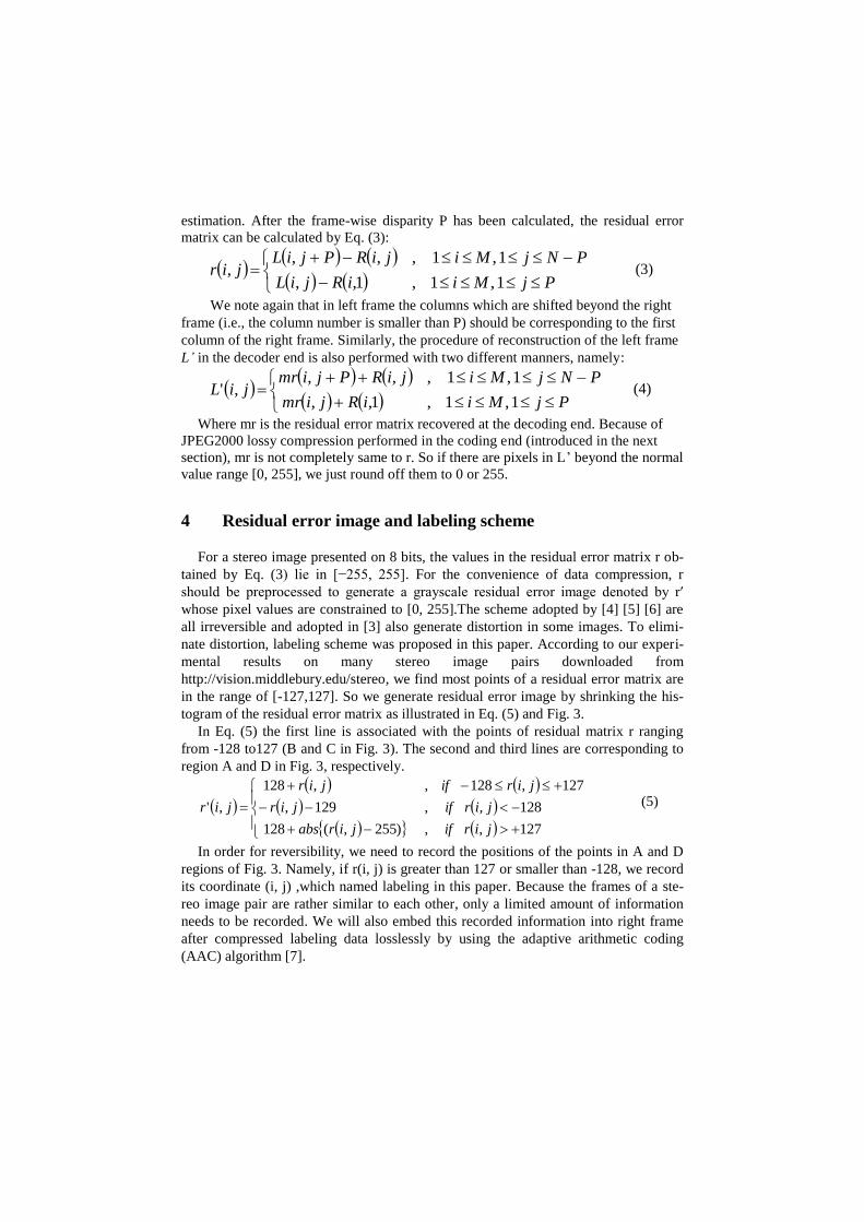
togram of the residual error matrix as illustrated in Eq. (5) and Fig. 3.
In Eq. (5) the first line is associated with the points of residual matrix r ranging
from -128 to127 (B and C in Fig. 3). The second and third lines are corresponding to
region A and D in Fig. 3, respectively.
127,,)255,(128
128,,129,
127,128,,128
,'
jirifjirabs
jirifjir
jirifjir
jir (5)
In order for reversibility, we need to record the positions of the points in A and D
regions of Fig. 3. Namely, if r(i, j) is greater than 127 or smaller than -128, we record
its coordinate (i, j) ,which named labeling in this paper. Because the frames of a ste-
reo image pair are rather similar to each other, only a limited amount of information
needs to be recorded. We will also embed this recorded information into right frame
after compressed labeling data losslessly by using the adaptive arithmetic coding
(AAC) algorithm [7].
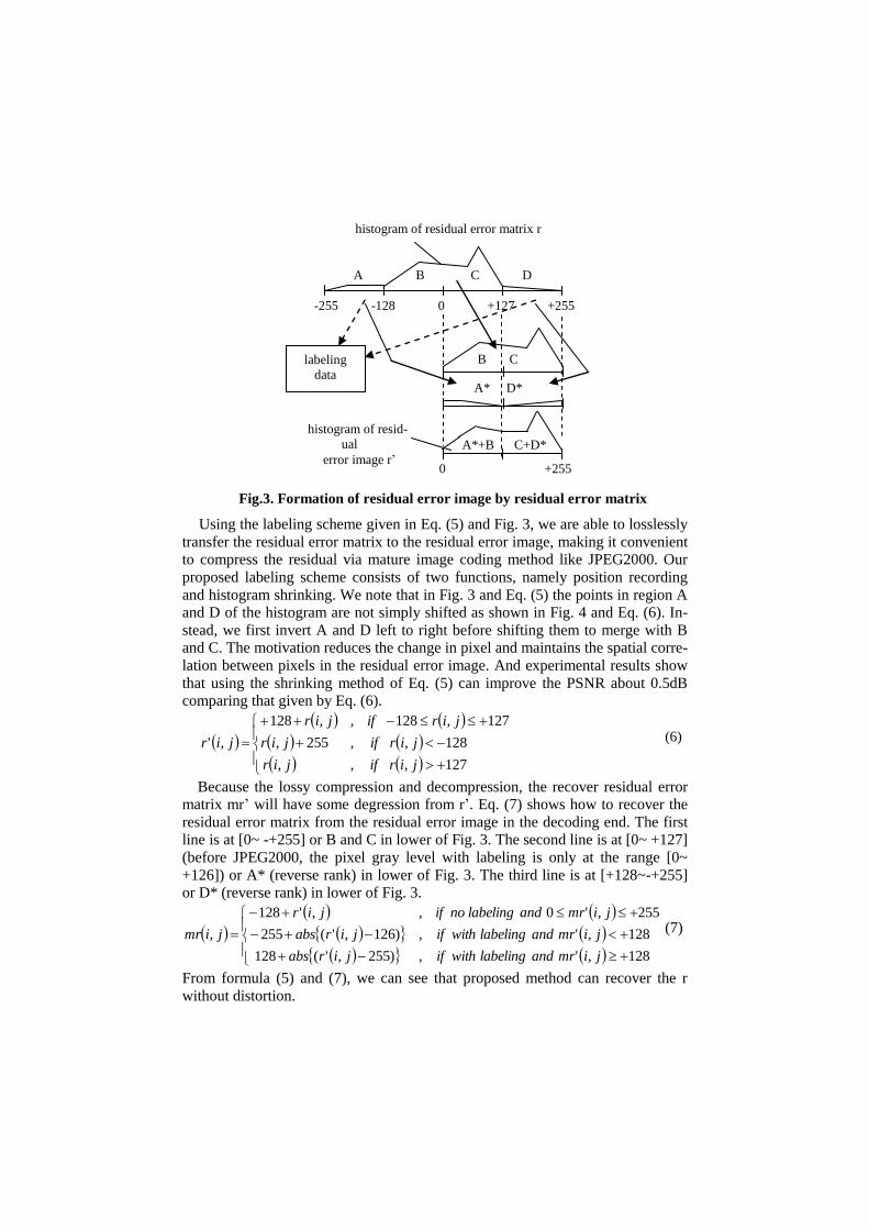
Fig.3. Formation of residual error image by residual error matrix
Using the labeling scheme given in Eq. (5) and Fig. 3, we are able to losslessly
transfer the residual error matrix to the residual error image, making it convenient
to compress the residual via mature image coding method like JPEG2000. Our
proposed labeling scheme consists of two functions, namely position recording
and histogram shrinking. We note that in Fig. 3 and Eq. (5) the points in region A
and D of the histogram are not simply shifted as shown in Fig. 4 and Eq. (6). In-
stead, we first invert A and D left to right before shifting them to merge with B
and C. The motivation reduces the change in pixel and maintains the spatial corre-
lation between pixels in the residual error image. And experimental results show
that using the shrinking method of Eq. (5) can improve the PSNR about 0.5dB
comparing that given by Eq. (6).
127,,,
128,,255,
127,128,,128
,'
jirifjir
jirifjir
jirifjir
jir (6)
Because the lossy compression and decompression, the recover residual error
matrix mr’ will have some degression from r’. Eq. (7) shows how to recover the
residual error matrix from the residual error image in the decoding end. The first
line is at [0~ -+255] or B and C in lower of Fig. 3. The second line is at [0~ +127]
(before JPEG2000, the pixel gray level with labeling is only at the range [0~
+126]) or A* (reverse rank) in lower of Fig. 3. The third line is at [+128~-+255]
or D* (reverse rank) in lower of Fig. 3.
128,',)255,'(128
128,',)126,'(255
255,'0,,'128
,
jimrandlabelingwithifjirabs
jimrandlabelingwithifjirabs
jimrandlabelingnoifjir
jimr (7)
From formula (5) and (7), we can see that proposed method can recover the r
without distortion.
A B C D
-255 -128 0 +127 +255
B C
A* D*
A*+B C+D*
0 +255
histogram of resid-
ual
error image r’
histogram of residual error matrix r
labeling
data
Fig.4. Simple formation of residual error image by residual error matrix
5 Large payload Optimal Histogram-pair Image Reversible
Data Hiding
The data hiding approach employed in this paper is an extension of the one given in
[2], namely our proposed Optimal Histogram-pair and Prediction-error based Image
Reversible data hiding approach. The major improvement made here is that using
multiple circle embedding scheme in order for large capacity of data hiding. The out-
put image of each pass of circle embedding is the input image of the next pass (refer
to Fig. 5 and Table 1 and 2). The embedding capacity of the approach in [2] is 0.7bpp,
which is satisfying for authentication. But it is not large enough for stereo image cod-
ing, because we cannot accomplish the coding unless the compression ratio on the left
frame is smaller than 0.1 (0.7/8). In order to guarantee the high quality of recovery a
data hiding approach with large capacity is required. With our newly proposed multi-
ple circle embedding the embedding capacity is clearly improved, say, to 2.6bpp (5
pass) and 1.6 bpp (4 pass) for Baby and Tsukuba, respectively. The detailed setting of
the data hiding approach used in this paper is given in Table 1 and 2. In our imple-
mentation we employ the numbers of circle 4 and 6 for the two stereo image pairs.
In order to explain the parameters involved in Table 1 and 2, we simply introduce
the process of our proposed histogram-pair based reversible data hiding approach.
This data hiding approach was first proposed by our group in 2007 [9] where the
readers may find some detailed introductions. The data, a binary sequence, is hided in
the image by modifying the magnitude in the transform domain.
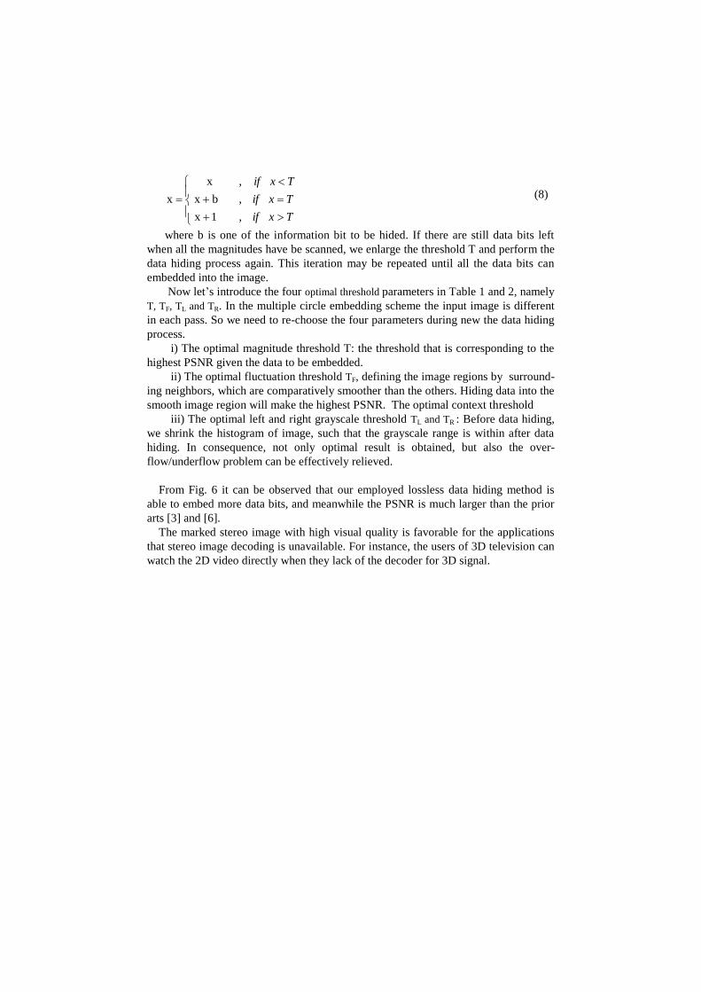
When hiding the data, we first define a threshold T. Then from the beginning of
the image, say the top left, each magnitude x is modified as follows.
A B C D
-255 -128 0 +127 +255
B C
A D
A+B C+D
0 +255
histogram of resid-
ual
error image r’
histogram of residual error matrix r
labeling
data
Txif
Txif
Txif
,1 x
,bx
,x
x
(8)
where b is one of the information bit to be hided. If there are still data bits left
when all the magnitudes have be scanned, we enlarge the threshold T and perform the
data hiding process again. This iteration may be repeated until all the data bits can
embedded into the image.
Now let’s introduce the four optimal threshold parameters in Table 1 and 2, namely
T, TF, TL and TR. In the multiple circle embedding scheme the input image is different
in each pass. So we need to re-choose the four parameters during new the data hiding
process.
i) The optimal magnitude threshold T: the threshold that is corresponding to the
highest PSNR given the data to be embedded.
ii) The optimal fluctuation threshold TF, defining the image regions by surround-
ing neighbors, which are comparatively smoother than the others. Hiding data into the
smooth image region will make the highest PSNR. The optimal context threshold
iii) The optimal left and right grayscale threshold TL and TR : Before data hiding,
we shrink the histogram of image, such that the grayscale range is within after data
hiding. In consequence, not only optimal result is obtained, but also the over-
flow/underflow problem can be effectively relieved.
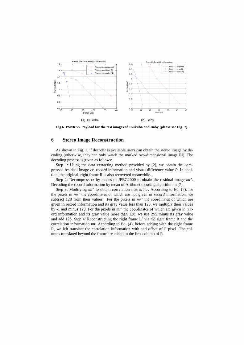
From Fig. 6 it can be observed that our employed lossless data hiding method is
able to embed more data bits, and meanwhile the PSNR is much larger than the prior
arts [3] and [6].
The marked stereo image with high visual quality is favorable for the applications
that stereo image decoding is unavailable. For instance, the users of 3D television can
watch the 2D video directly when they lack of the decoder for 3D signal.
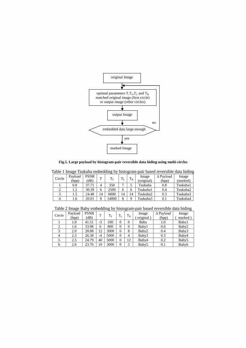
Fig.5. Large payload by histogram-pair reversible data hiding using multi-circles
Table 1 Image Tsukuba embedding by histogram-pair based reversible data hiding
Circle Payload
(bpp)
PSNR
(dB) T TF TL TR
Image
(original)
Δ Payload
(bpp)
Image
(marked)
1 0.8 37.71 4 350 7 5 Tsukuba 0.8 Tsukuba1
2 1.2 30.39 6 2500 6 6 Tsukuba1 0.4 Tsukuba2
3 1.5 24.48 14 6000 14 14 Tsukuba2 0.3 Tsukuba3
4 1.6 20.01 8 14000 8 9 Tsukuba3 0.1 Tsukuba4
Table 2 Image Baby embedding by histogram-pair based reversible data hiding
Circle Payload
(bpp)
PSNR
(dB) T TF TL TR
Image
( original )
Δ Payload
(bpp)
Image
( marked )
1 1.0 41.51 -3 100 0 0 Baby 1.0 Baby1
2 1.6 33.98 6 800 0 0 Baby1 0.6 Baby2
3 2.0 28.88 12 3000 6 8 Baby2 0.4 Baby3
4 2.3 26.38 -4 5000 0 4 Baby3 0.3 Baby4
5 2.5 24.79 40 5000 0 12 Baby4 0.2 Baby5
6 2.6 23.76 10 3000 0 3 Baby5 0.1 Baby6
original Image
optimal parameters T,TF,TL and TR
matched original image (first circle)
or output image (other circles)
output Image
marked Image
embedded data large enough
yes
no
15 20 25 30 35 400.4
0.6
0.8
1
1.2
1.4
1.6
1.8
Reversible Data Hiding Comparison
Paylo
ad (
bpp)
PSNR (dB)
Tsukuba—proposed
Tsukuba—chen [3]
Tsukuba—coltuc[4]
15 20 25 30 35 40 450.8
1
1.2
1.4
1.6
1.8
2
2.2
2.4
2.6 Reversible Data Hiding Comparison
Paylo
ad (
bpp)
PSNR (dB)
Baby-----—proposed
Baby-----—chen [3]
Baby—-----coltuc[4]
(a) Tsukuba (b) Baby
Fig.6. PSNR vs. Payload for the test images of Tsukuba and Baby (please see Fig. 7).
6 Stereo Image Reconstruction
As shown in Fig. 1, if decoder is available users can obtain the stereo image by de-
coding (otherwise, they can only watch the marked two-dimensional image EI). The
decoding process is given as follows:
Step 1: Using the data extracting method provided by [2], we obtain the com-
pressed residual image cr, record information and visual difference value P. In addi-
tion, the original right frame R is also recovered meanwhile.
Step 2: Decompress cr by means of JPEG2000 to obtain the residual image mr’.
Decoding the record information by mean of Arithmetic coding algorithm in [7].
Step 3: Modifying mr’ to obtain correlation matrix mr. According to Eq. (7), for
the pixels in mr’ the coordinates of which are not given in record information, we
subtract 128 from their values. For the pixels in mr’ the coordinates of which are
given in record information and its gray value less than 128, we multiply their values
by -1 and minus 129. For the pixels in mr’ the coordinates of which are given in rec-
ord information and its gray value more than 128, we use 255 minus its gray value
and add 128. Step 4: Reconstructing the right frame L’ via the right frame R and the
correlation information mr. According to Eq. (4), before adding with the right frame
R, we left translate the correlation information with and offset of P pixel. The col-
umns translated beyond the frame are added to the first column of R.
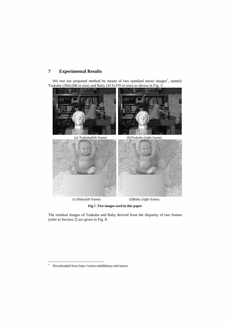
7 Experimental Results
We test our proposed method by means of two standard stereo images1, namely
Tsukuba (384x288 in size) and Baby (413x370 in size) as shown in Fig. 3.
(a) Tsukuba(left frame) (b)Tsukuba (right frame)
(c) Baby(left frame) (d)Baby (right frame)
Fig.7. Test images used in this paper
The residual images of Tsukuba and Baby derived from the disparity of two frames
(refer to Section 2) are given in Fig. 8.
1 Downloaded from http://vision.middlebury.edu/stereo
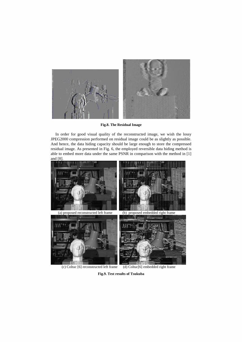
Fig.8. The Residual Image
In order for good visual quality of the reconstructed image, we wish the lossy
JPEG2000 compression performed on residual image could be as slightly as possible.
And hence, the data hiding capacity should be large enough to store the compressed
residual image. As presented in Fig. 6, the employed reversible data hiding method is
able to embed more data under the same PSNR in comparison with the method in [1]
and [8].
(a) proposed reconstructed left frame (b) proposed embedded right frame
(c) Coltuc [6] reconstructed left frame (d) Coltuc[6] embedded right frame
Fig.9. Test results of Tsukuba
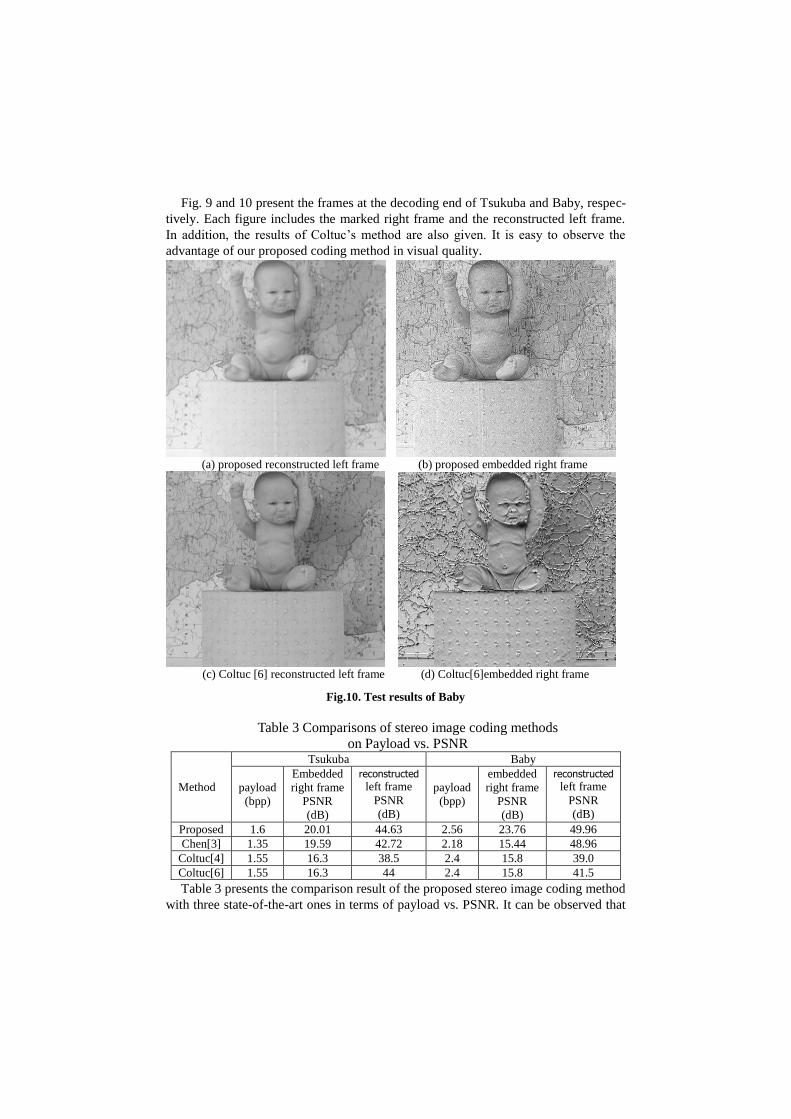
Fig. 9 and 10 present the frames at the decoding end of Tsukuba and Baby, respec-
tively. Each figure includes the marked right frame and the reconstructed left frame.
In addition, the results of Coltuc’s method are also given. It is easy to observe the
advantage of our proposed coding method in visual quality.
Marked (baby-Marked) Image Histogram
(a) proposed reconstructed left frame (b) proposed embedded right frame
(c) Coltuc [6] reconstructed left frame (d) Coltuc[6]embedded right frame
Fig.10. Test results of Baby
Table 3 Comparisons of stereo image coding methods
on Payload vs. PSNR
Method
Tsukuba Baby
payload
(bpp)
Embedded
right frame
PSNR
(dB)
reconstructed left frame
PSNR
(dB)
payload
(bpp)
embedded
right frame
PSNR
(dB)
reconstructed left frame
PSNR
(dB)
Proposed 1.6 20.01 44.63 2.56 23.76 49.96
Chen[3] 1.35 19.59 42.72 2.18 15.44 48.96
Coltuc[4] 1.55 16.3 38.5 2.4 15.8 39.0
Coltuc[6] 1.55 16.3 44 2.4 15.8 41.5
Table 3 presents the comparison result of the proposed stereo image coding method
with three state-of-the-art ones in terms of payload vs. PSNR. It can be observed that
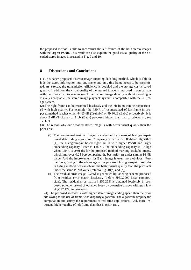
the proposed method is able to reconstruct the left frames of the both stereo images
with the largest PSNR. This result can also explain the good visual quality of the de-
coded stereo images illustrated in Fig. 9 and 10.
8 Discussions and Conclusions
(1) This paper proposed a stereo image encoding/decoding method, which is able to
hide the stereo information into one frame and only this frame needs to be transmit-
ted. As a result, the transmission efficiency is doubled and the storage cost is saved
greatly. In addition, the visual quality of the marked image is improved in comparison
with the prior arts. Because to watch the marked image directly without decoding is
visually acceptable, the stereo image playback system is compatible with the 2D im-
age system.
(2) The right frame can be recovered losslessly and the left frame can be reconstruct-
ed with high quality. For example, the PSNR of reconstructed of left frame in pro-
posed method reaches either 44.63 dB (Tsukuba) or 49.96dB (Baby) respectively. It is
about 2 dB (Tsukuba) or 1 db (Baby) proposed higher than that of prior-arts , see
Table 3.
(3) The reason why our decoded stereo image is with better visual quality than the
prior arts:
(i) The compressed residual image is embedded by means of histogram-pair
based data hiding algorithm. Comparing with Tian’s DE-based algorithm
[1], the histogram-pair based algorithm is with higher PSNR and larger
embedding capacity. Refer to Table 3, the embedding capacity is 1.6 bpp
when PSNR is 20.01 dB for the proposed method marking Tsukuba image,
which improves 0.25 bpp comparing the best prior art under similar PSNR
value. And the improvement for Baby image is even more obvious. Fur-
thermore, owing to the advantage of the proposed histogram-pair based da-
ta hiding method, we can obtain the better visual quality than the prior arts
under the same PSNR value (refer to Fig. 10(a) and (c)).
(ii) The residual error image [0,255] is generated by labeling scheme proposed
from residual error matrix losslessly (before JPEG2000 lossy compres-
sion). The residual error matrix [-255,255] is obtained losslessly in pro-
posed scheme instead of obtained lossy by downsize images with gray lev-
el [-127,127] in prior-arts.
(4) The proposed method is with higher stereo image coding speed than the prior
arts owing to the use of frame-wise disparity algorithm. The algorithm simplify the
computation and satisfy the requirement of real time applications. And, more im-
portant, higher quality of left frame than that in prior-arts .
References:
[1] J. Tian. Reversible data embedding using a difference expansion. IEEE Trans.
Circuits Syst. Video Technol.,13: 890-896, 2003.
[2]G. Xuan, X. Tong, J. Teng, X. Zhang, Y.Q. Shi, "Optimal Histogram-pair and
Prediction-error Based Image Reversible Data Hiding", 11th International Work-
shop on Digital-forensics and Watermarking (IWDW 2012), Oct 31-Nov. 3, 2012,
Shanghai, China
[3] H.Chen. An Effective Stereo Image Coding Method with Reversible Water-
marking. Journal of Computational Information Systems 8: 7 (2012) 2761–2768
[4] D. Coltuc, I. Caciula. Stereo Embedding by Reversible Watermarking: Further
Results. In Proc. of Int. Symposium on Signals, Circuits and Systems, pp. 1-4,
2009.
[5] J. N. Ellinas. Reversible watermarking on stereo image sequences. Interna-
tional Journal of Signal Processing, 5(3): 210-215, 2009.
[6] D. Coltuc. On stereo embedding by reversible watermarking. in Proc. of Int.
Symposium on Signals,Circuits and Systems, pp. 1-4, 2007.
[7] W. Fred. An adaptive arithmetic coding library,
http://www.cipr.rpi.edu/swheeler/ac.
[8] D.Coltuc. ”Improved Capacity Reversible Watermarking”, IEEE International
Conference on Image Processing( ICIP 2007), San Antonio,Texas, USA,vol. 3,
pp.249-252, 2007. [9] G. Xuan, Y. Q. Shi, P. Chai, X. Cui, Z. Ni, X. Tong, “Optimum histogram pair
based image lossless data embedding,” Proceedings of International Workshop on
Digital Watermarking, (IWDW07) Guangzhou, China, December 2007.
![course.ece.cmu.eduece796/documents/MPEG-1... · Web viewMS stereo [audio]: A method of exploiting stereo irrelevance or redundancy in stereophonic audio programmes based on coding](https://static.fdocuments.net/doc/165x107/60cebdf0d6e288136150cf52/ece796documentsmpeg-1-web-view-ms-stereo-audio-a-method-of-exploiting.jpg)


![영상처리 실습 #4 Histogram 연산 [ Histogram 대화상자 만들기 ]. Histogram 대화상자 만들기.](https://static.fdocuments.net/doc/165x107/5697bfe71a28abf838cb5e1a/-4-histogram-histogram-.jpg)