Stepping Motor and Driver Package AR Series · Stepping Motor and Driver Package The AR Series...
56
Stepping Motor and Driver Package The AR Series substantially reduces heat generation from the motor through use of high-efficiency technology. A pulse input type and a newly released built-in controller type are available. High-Efficiency AR Series AC Input Pulse Input Type Built-in Controller Type
Transcript of Stepping Motor and Driver Package AR Series · Stepping Motor and Driver Package The AR Series...

Stepping Motor and Driver Package
The AR Series substantially reduces heat generation from the motor
through use of high-effi ciency technology. A pulse input type and a
newly released built-in controller type are available.
High-Effi ciency AR Series AC Input
Pulse Input Type
Built-in Controller Type

2
Maintains Operation Even During ◇Abrupt Load Fluctuations and
Accelerations.
The AR Series uses our closed loop
control to maintain positioning operation
even during abrupt load fluctuations and
accelerations. The rotor position detection
sensor monitors the rotation.
When an overload condition is detected,
the AR Series will instantaneously regain
control using the closed loop mode.
Alarm Signal Output in Case of ●Abnormality
If an overload is applied continuously, an
alarm signal is output. When the positioning
is complete, an END signal is output. This
ensures the same level of reliability achieved
by a servo motor.
Rotor Position Detection Sensor ◇The rotor position detection sensor uses the
change in inductance caused by change in
the distance between the stator teeth and
the teeth on the sensor rotor to detect rotor
position.
This structure can be made small and thin, ●so the overall size of the motor can be
reduced.
High resolution ●This structure ●does not use
electronic parts,
so it is not
affected by heat
or vibration.
Input
Sig
nal
Input
Counter
Deviation
Counter
Rotor Position
Counter
Exc
itati
on S
equence
Contr
ol
Out
put
Elem
ent
Motor
Sensor
Normal (Positioning deviation is less than ±1.8°)
Motor runs in open loop mode like a stepping motor.
During Overload Condition (Positioning deviation is ±1.8° or more)
The closed loop mode is engaged to maintain the
positioning operation.
Sensor detects rotor position
Adopting Oriental Motor’s Original Closed Loop Control
AR Series AC Input with newly released Built-In
Controller Type
Features of the AR Series Features of the Built-In Controller Type
Necessary Operation Information is
Built into the Driver
Connection to Superior System
Lower Heat Generation
High Precision Positioning with
Compact High-Torque Motors
Adopting Oriental Motor’s Original
Closed Loop Control
● Positioning Operation
● Modbus (RTU) Control
● Return-to-Home Operation
● I/O Control
● Continuous Operation
● JOG Operation, Automatic Return Operation
NEW
Featu
res
Lin
eu
pS
yste
m C
on
fi gu
ratio
nP
rod
uc
t Lin
eS
pe
cifi c
atio
ns
an
d
Ch
ara
cte
ristic
sD
ime
ns
ion
sC
on
nec
tion
an
d
Op
era
tion
Lis
t of M
oto
r an
d
Driv
er C
om
bin
atio
ns
Acce
sso
ries

3
Temperature Distribution by Thermography●
Comparison under the same conditions
AR66AC-◇ Conventional Model
Motor Case Temperature under Same Operating ●Conditions
120
100
80
60
40
0
0 20 40 60 80 100 120 140 160 180
Time [min]
Tem
per
atu
re [
°C]
AR66AC-◇Conventional Model
Lower Heat Generation ◇The AR Series utilizes high-efficiency technology to achieve a
significant reduction in the amount of heat generated from the
motor.
Energy-Saving ◇Power consumption: up to 66% less than a conventional model
Power Consumption●
800
700
600
500
400
300
200
100
0
Pow
er C
onsu
mpt
ion
[ kW
h/Ye
ar]
Conventional Model AR66AC-◇
Power Consumption
66% Reduction
CO2 emission: up to 66% less✽ than a conventional model
Operating Condition✽
Speed: 1000 r/min, Load Factor: 50%
Operating Time: 24 hours of operation (70% operating, 25% standing by, 5% standstill), 365 days/year
Continuous Operation is Achieved Due to the Reduction of Motor Heat Generation by Utilizing High-Effi ciency Technology
Featu
res
Lin
eu
pS
yste
m C
on
fi gu
ratio
nP
rod
uc
t Lin
eS
pe
cifi c
atio
ns
an
d
Ch
ara
cte
ristic
sD
ime
ns
ion
sC
on
nec
tion
an
d
Op
era
tion
Lis
t of M
oto
r an
d
Driv
er C
om
bin
atio
ns
Acce
sso
ries

4
Featu
res
Lin
eu
pS
yste
m C
on
fi gu
ratio
nP
rod
uc
t Lin
eS
pe
cifi c
atio
ns
an
d
Ch
ara
cte
ristic
sD
ime
ns
ion
sC
on
nec
tion
an
d
Op
era
tion
Lis
t of M
oto
r an
d
Driv
er C
om
bin
atio
ns
Acce
sso
ries
User-Friendly and Easy, Highly Accurate Positioning ◇Stepping motors provide convenient means to ensure highly
accurate positioning because they synchronize themselves with
commands without requiring feedback.
High Response ◇The motor operates
synchronously with pulse
commands to achieve high
response. There’s no delay in
operation following a pulse
command.
Pulse Command
Motor Operation Waveform
Positioning Completion Signal
Capable of Driving Large Inertial Loads ●Stepping motors can drive larger inertial loads than servo motors of equivalent frame sizes.
Comparison at 30 times of the rotor inertia●
AR SeriesLoad Inertia 22.4×10⁻⁴ kg·m2
(30 times the rotor inertial moment)
Load Inertia: Diameter: 169 mm,
Thickness: 10 mm,
Material: Aluminum
Motor: Frame size 60 mm
Length 90 mm
Conventional Servo MotorLoad Inertia 4.0×10⁻⁴ kg·m2
(30 times the rotor inertia)
Load Inertia: Diameter: 110 mm,
Thickness: 10 mm,
Material: Aluminum
Motor: Frame size 60 mm
Length 96.5 mm
No Tuning ◇With the AR Series, you can
perform positioning quickly after
a load change, etc., without
adjusting any gains.
No Hunting ◇Because it uses a stepping
motor, the AR Series does
not hunt when stopped.
Accordingly, the AR Series is
ideal for applications where the
equipment uses a belt-drive
mechanism or otherwise has low
rigidity and you don’t want it to
vibrate when stopping.
Beneficial Features of a Stepping Motor

Featu
res
Lin
eu
pS
yste
m C
on
fi gu
ratio
nP
rod
uc
t Lin
eS
pe
cifi c
atio
ns
an
d
Ch
ara
cte
ristic
sD
ime
ns
ion
sC
on
nec
tion
an
d
Op
era
tion
Lis
t of M
oto
r an
d
Driv
er C
om
bin
atio
ns
Acce
sso
ries
5
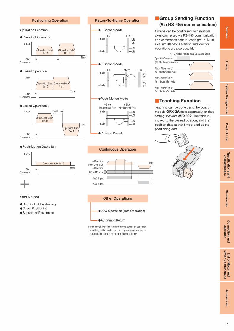
Types of Operation Systems ■
Stepping motor and driver packages combine a stepping motor selected from various types with a dedicated driver. In addition to the pulse
input type, drivers with a built-in controller type is also available. You can select a desired combination product according to the required
operation system. Different drivers are explained below by using the AR Series as an example.
Pulse Input Packages
The motor can be controlled using a pulse generator provided
by the customer. Operating data is input to the pulse generator
beforehand, and you select the operating data on the programmable
controller, then input the operation command.
DriverMotor
Pulse Generator ProgrammableController
Built-In Controller Packages
A built-in pulse generator allows the motor to be driven via a directly
connected programmable controller. Since no separate pulse
generator is required, the drivers of this type save space.
RS-485 communication (Modbus RTU) is also available.
Driver
Sensor
ProgrammableController
Data SettingSoftware
Computer
Control Module
or
Motor

6
Featu
res
Lin
eu
pS
yste
m C
on
fi gu
ratio
nP
rod
uc
t Lin
eS
pe
cifi c
atio
ns
an
d
Ch
ara
cte
ristic
sD
ime
ns
ion
sC
on
nec
tion
an
d
Op
era
tion
Lis
t of M
oto
r an
d
Driv
er C
om
bin
atio
ns
Acce
sso
ries
Built-In Controller Package ■
Item Content
Common
Control MethodI/O Control
RS-485 communication Modbus RTU Protocol Connection
Position Command
InputSet with operating data number Command range per point: −8388608∼8388607 [steps] (setting unit: 1 [step])
Speed Command Input Set with operating data number Command range: 0∼1000000 [Hz] (setting unit: 1 [Hz])
Acceleration/
Deceleration
Command Input
Set with operating data number or parameters.
Acceleration/deceleration rate [ms/kHz] or acceleration/deceleration time [s] can be selected.
Command range: 0.001∼1000.000 [ms/kHz] (setting unit: 0.001 [ms/kHz])
0.001∼1000.000 [s] (setting unit: 0.001 [s])
Acceleration/
Deceleration ControlVelocity filter, moving average filter
Return-To-Home
Operation
Return-To-Home
Method
2-sensor mode This is the return-to-home operation using limit sensors (+LS, −LS).
3-sensor mode This is the return-to-home operation using limit sensors and HOME sensor.
Pushing mode✽ This is the return-to-home operation for pushing to the mechanical end of a linear slide, etc.
Position preset
This function allows a home position to be confirmed by inputting P-PRESET using an arbitrary
position.
An arbitrary value can be set for the home position.
Positioning
Operation
Number of Positioning
Points64 points (No. 0∼63)
Operation ModeIncremental mode (Relative positioning)
Absolute mode (Absolute positioning)
Operation Functions
One-shot operation This is a PTP (Point to Point) positioning operation.
Linked operation This is a multistep speed-change positioning operation linked to operating data.
Linked operation 2
This is a positioning operation with timer linked to operating data.
The timer (dwell time) can be set in the range of 0∼50.000 [s].
(Setting unit: 0.001 [s])
Push-motion operation✽ Continuous pressurizing position operations are performed with respect to load.
The operating speed is maximum 30 [r/min] with the motor shaft.
Starting Methods
Operating data selection mode The positioning operation starts when START is input after M0∼M5 has been selected.
Direct mode (direct positioning)The positioning operation starts with the operating data number that was set with the
parameters when MS0∼MS5 has been input.
Sequential mode (sequential positioning) The positioning operation starts in order from operating data No. 0 every time SSTART is input.
Continuous
Operation
Number of Speed
Points64 points (No. 0∼63)
Speed-Change Method This switches the operating data number.
Other Operations
JOG Operation +JOG or −JOG is input, and regular feeding is performed.
Automatic Return
Operation
This automatically returns to the original stopped position when the motor has become misaligned due to an external force during non-
excitation.
Do not perform push-motion operations with geared types. Doing so will damage the motor and gearhead. ✽
The burden on the programmable PLC is
reduced because the information necessary
for motor operations is built into the driver.
This simplifies the system configuration for
multi-axis control.
Set with control module (sold separately),
data setting software, or RS-485
communication.
Basic Settings
(Factory settings)
Operation Data Settings
Parameter ChangesData Setting
Test Operation
Alarm History
Parameter Changes
Monitor
Data Copy
Control Module
(OPX-2A)
Connection Cable
Driver
Motor
or
Data Setting Software (MEXE02)
Setting via RS-485 communication is also possible. ●
Operation type ●With built-in controller packages, the motor’s operating speed and traveling amount are set with operating data and operations performed
based on the selected operating data. The operation type is 4-pattern.
Featu
res
Lin
eu
pS
yste
m C
on
fi gu
ratio
nP
rod
uc
t Lin
eS
pe
cifi c
atio
ns
an
d
Ch
ara
cte
ristic
sD
ime
ns
ion
sC
on
ne
ctio
n a
nd
Op
era
tion
Lis
t of M
oto
r an
d
Driv
er C
om
bin
atio
ns
Acce
sso
ries
7
This comes with the return-to-home operation sequence ●installed, so the burden on the programmable master is
reduced and there is no need to create a ladder.
One-Shot Operation●
2-Sensor Mode●
3-Sensor Mode●
Push-Motion Mode●
JOG Operation (Test Operation)●
Position Preset●
Automatic Return ●
Data-Select Positioning●Direct Positioning●Sequential Positioning●
Operation Function
Start Method
Linked Operation●
Linked Operation 2●
Push-Motion Operation●
Speed
TimeStart
Command
Operation Data
No. 0
Operation Data
No. 1
−LS +LS
—VR—VS
—VS—VR−Side
+Side
HOMES−LS +LS
−Side
+Side —VR—VS
—VS—VR
—VR—VS
—VS—VR
−Side
Mechanical End
+Side
Mechanical End
−Side
+Side
Speed
TimeStart
Command
Operation Data
No. 0
Operation Data
No. 1
Dwell TimeSpeed
Time
Start
Command
Operation Data
No. 0
Operation Data
No. 1
Speed
Start
Command
Time
Operation Data No. 0
Group Sending Function ■
(Via RS-485 communication)
Groups can be configured with multiple
axes connected via RS-485 communication,
and commands sent for each group. Multi-
axis simultaneous starting and identical
operations are also possible.
Teaching Function ■
Teaching can be done using the control
module OPX-2A (sold separately) or data
setting software MEXE02. The table is
moved to the desired position, and the
position data at that time stored as the
positioning data.
No. 0 Motor Positioning Operation Start
Motor Movement of
No. 0 Motor (Main Axis)
Motor Movement of
No. 1 Motor (Sub Axis)
Motor Movement of
No. 2 Motor (Sub Axis)
Operation Command
(RS-485 Communication)
Positioning Operation Return-To-Home Operation
Other Operations
Continuous Operation
−Direction
+Direction
Motor OperationTime
FWD Input
RVS Input
M0 to M5 Input

8
Featu
res
Lin
eu
pS
yste
m C
on
fi gu
ratio
nP
rod
uc
t Lin
eS
pe
cifi c
atio
ns
an
d
Ch
ara
cte
ristic
sD
ime
ns
ion
sC
on
nectio
n a
nd
Op
era
tion
Lis
t of M
oto
r an
d
Driv
er C
om
bin
atio
ns
Acces
so
ries
By using the data setting
software and control module,
sold separately, parameters can
be changed, the alarm history
displayed, and each monitor
handled according to your
demands.
Pulse Input Package ■
Item OverviewBasic
Settings
Extended
Settings
Pulse Input Mode Selection
1-pulse input mode or 2-pulse input mode (negative logic) can be selected. ● ●Beyond the normal settings, the phase difference input can also be set.
· 1-pulse mode (positive logic/negative logic)
· 2-pulse mode (positive logic/negative logic)
· Phase difference input (1×/2×/4×)
− ●
Resolution Setting
The resolution can be selected with a function switch (D0, D1, CS0, CS1). ● ●The value of the electronic gears corresponding to each function switch (D0, D1, CS0, CS1) can be
changed. − ●
Running Current Setting
The running current setting can be changed with the current setting switch (CURRENT). ● ●The value corresponding to each stage of the current setting switch (CURRENT), 0∼F (16 stages), can be
changed. − ●
Standstill Current Ratio Setting The ratio of the standstill current with respect to the running current can be set. − ●Motor Rotation Coordinate Setting The motor's rotation coordinate can be set. − ●
All Windings On Signal (C-ON input)This is the input signal for exciting the motor. ● ●The logic of the C-ON input during power supply input can be set. − ●
Excitation Position Return-To-Home Operation
when All Windings are On Enabled/Disabled
Whether or not an operation to return to the excitation position (deviation 0 position) is performed when
all windings are on can be set. − ●
I/O Input Signal Mode Selection Input when a push-motion operation is performed. − ●Alarm Code Signal Enabled/Disabled Set when code output is desired when an alarm has occurred. − ●END Signal Output Width Setting The END signal output width can be changed. − ●END Signal Output Offset The END signal output value can be offset. − ●A/B Phase Output This can be used to confirm the position of the motor. ● ●Timing Signal Output This is output every time the motor rotates 7.2˚. ● ●
Velocity Filter SettingThis places a filter on the operation command and suppresses motor behavior. ● ●The value corresponding to each stage of the setting switch, 0∼F (16 stages), can be changed. − ●
Vibration Suppression Function for Normal ModeThis can be set to suppress resonance vibration during rotation. − ●This can be set to suppress vibration during acceleration and deceleration, and when stopped. − ●
Gain Adjustment for Current Control Mode✽
This adjusts the position/speed loop gain. − ●This adjusts the constant during velocity integration. − ●This sets the damping control vibration frequency. − ●This sets the damping control as enabled/disabled. − ●
Motor Excitation Position Selection When Power
is OnThe motor excitation position when the power is on can be selected. − ●
Control Module SettingsWhether the speed display of the control module is signed or an absolute value can be selected. − ●The geared motor gear ratio for the speed monitor can be set. − ●
Oriental Motor recommends using normal mode unless you want to further reduce heat generation and noise. ✽
Main Additional Functions from Extended Settings ●
Data Copy
Motor
Basic Settings
(Factory settings)
Extended SettingsPush-Motion Operation
Test Operation
Alarm History
Parameter Changes
Monitor
Control Module
(OPX-2A)
or
Connection Cable
Driver
Data Setting Software (MEXE02)

Featu
res
Lin
eu
pS
yste
m C
on
fi gu
ratio
nP
rod
uc
t Lin
eS
pe
cifi c
atio
ns
an
d
Ch
ara
cte
ristic
sD
ime
ns
ion
sC
on
nec
tion
an
d
Op
era
tion
Lis
t of M
oto
r an
d
Driv
er C
om
bin
atio
ns
Acce
sso
ries
9
Motor Lineup ■
Characteristics Comparison for Motors and Geared Motors ●
4000
500
600
70
0.0072
3 (0.05)
0.012
25 (0.42)
0.36
45 (0.75)
0.0072
0.0036 0
600
Backlash[arc min (degrees)]
Basic model of the AR Series
(Planetary)
(Planetary)
(Harmonic drive)
(Parallel shaft)
PS Geared
TH Geared
Standard
PN Geared
Harmonic Geared
· A wide variety of low gear ratios,
high-speed operations
· Gear Ratio Types
3.6, 7.2, 10, 20, 30
· High Permissible Torque/Maximum Torque
· A wide variety of gear ratios for selecting the
desired step angle
· Center Shaft
· Gear Ratio Types
5, 7.2, 10, 25, 36, 50
· High Speed (Low gear ratio),
High Positioning Accuracy
· High Permissible Torque/Maximum Torque
· A wide variety of gear ratios for selecting the
desired step angle
· Center Shaft
· Gear Ratio Types
5, 7.2, 10, 25, 36, 50
· High Positioning Accuracy
· High Permissible Torque/Maximum Torque
· High Gear Ratio, High Resolution
· Center Shaft
· Gear Ratio Types
50, 100
Note
The values shown above must be used as reference. These values vary depending on the frame size and gear ratio.●
Power Supply Voltage and Range of Motor Frame Size ●
Power Supply
Voltage
Motor Type
Standard Type
TH Geared Type
PS Geared Type
PN Geared Type
Harmonic Geared Type
Built-In Controller Package
Single-Phase
200-240 VAC
□42
□60
□85
□42
□60
□90
Pulse Input Package
Single-Phase
200-230 VAC
□42
□60
□85
□42
□60
□90
□● 42: indicates a motor frame size of 42 mm.
Electromagnetic brake models are available for all types.●

10
Featu
res
Lin
eu
pS
yste
m C
on
fi gu
ratio
nP
rod
uc
t Lin
eS
pe
cifi c
atio
ns
an
d
Ch
ara
cte
ristic
sD
ime
ns
ion
sC
on
nectio
n a
nd
Op
era
tion
Lis
t of M
oto
r an
d
Driv
er C
om
bin
atio
ns
Ac
cess
orie
s
③ Control Module ④ Data Setting Software
Accessories (Sold separately)✽2
Computer✽1
To USB
Port
For RS-485
Communication
or
⑤ Motor Mounting Brackets
⑥ MCS Couplings ⑦ Cable for RS-485 Communication
System Confi guration Example●
AR Series
Sold Separately
Motor Mounting
BracketsFlexible Couplings
AR66MCD-3 PAL2P-5 MCS201010
The system confi guration shown above is an example. Other combinations are available.●
System Configuration ■
Built-In Controller Package Standard Type with Electromagnetic Brake ●An example of a system configuration when used with either I/O control or RS-485 communication. ✽1 Not supplied ✽2 To be provided as necessary
Motor Driver
For Electromagnetic
Brake
For Motor
The product comes with a 1 m, 2 m or 3 m cable
(for motor and electromagnetic brake).
AR Series
Accessories (Sold separately)
Sensor✽1
Programmable Controller✽1
AC Power Supply✽1 (Main power supply)
(For electromagnetic brake) (For electromagnetic brake)
① Connection Cable Set Flexible Connection Cable Set
② Extension Cable Set Flexible Extension Cable Set
Accessories (Sold separately)
or
24 VDC Power Supply for Control✽1
Number Name Overview
①Connection Cable Sets
Flexible Connection Cable SetsThese cable sets are used to connect the motor and driver without using the included cables.
② Extension Cable Sets
Flexible Extension Cable SetsThese cable sets are used to extend the wiring distance between the motor and driver using the included cables.
③ Control Module This control module lets you set (edit, monitor, operate) various data and enables extended functions. Comes with a communication cable (5 m).
④ Data Setting SoftwareThis data setting software lets you set (edit, monitor, operate) various data and enables extended functions. Comes with a PC interface cable
(5 m) and a USB cable (0.5 m).
⑤ Motor Mounting Brackets Dedicated mounting bracket for the motor.
⑥ MCS Couplings Coupling that connects the motor shaft to the driven shaft.
⑦ Cable for RS-485 Communication These cables are used to link drivers when a built-in controller type is being operated in a multi-drop manner.
Featu
res
Lin
eu
pS
yste
m C
on
fi gu
ratio
nP
rod
uc
t Lin
eS
pe
cifi c
atio
ns
an
d
Ch
ara
cte
ristic
sD
ime
ns
ion
sC
on
nec
tion
an
d
Op
era
tion
Lis
t of M
oto
r an
d
Driv
er C
om
bin
atio
ns
Ac
cess
orie
s
11
⑥ Motor Mounting Brackets ⑦ MCS Couplings ⑧ General-Purpose Cables ⑨ Connector – Terminal Block Conversion Unit
System Confi guration Example●
AR Series
Sold Separately
ControllerMotor Mounting
Bracket
Flexible
Coupling
Connector – Terminal Block
Conversion Unit (1 m)
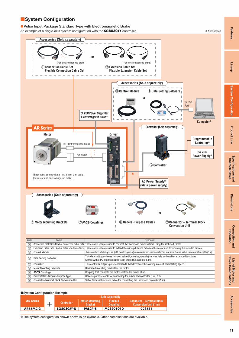
AR66MC-3 SG8030JY-U PAL2P-5 MCS201010 CC36T1
The system confi guration shown above is an example. Other combinations are available.●
System Configuration ■
Pulse Input Package Standard Type with Electromagnetic Brake ●An example of a single-axis system configuration with the SG8030JY controller. ✽ Not supplied
Motor Driver
For Electromagnetic Brake
For Motor
The product comes with a 1 m, 2 m or 3 m cable
(for motor and electromagnetic brake).
AR Series
Accessories (Sold separately)
⑤ Controller
Controller (Sold separately)
Computer✽
To USB
Port
24 VDC Power Supply✽
Programmable Controller✽
or
AC Power Supply✽ (Main power supply)
24 VDC Power Supply for Electromagnetic Brake✽
Number Name Overview
① Connection Cable Sets Flexible Connection Cable Sets These cable sets are used to connect the motor and driver without using the included cables.
② Extension Cable Sets Flexible Extension Cable Sets These cable sets are used to extend the wiring distance between the motor and driver using the included cables.
③ Control Module This control module lets you set (edit, monitor, operate) various data and enables extended functions. Comes with a communication cable (5 m).
④ Data Setting SoftwareThis data setting software lets you set (edit, monitor, operate) various data and enables extended functions.
Comes with a PC interface cable (5 m) and a USB cable (0.5 m).
⑤ Controller This controller outputs pulse commands that determine the rotating amount and rotating speed.
⑥ Motor Mounting Brackets Dedicated mounting bracket for the motor.
⑦ MCS Couplings Coupling that connects the motor shaft to the driven shaft.
⑧ Driver Cables General-Purpose Type General-purpose cable for connecting the driver and controller (1 m, 2 m).
⑨ Connector-Terminal Block Conversion Unit Set of terminal block and cable for connecting the driver and controller (1 m).
③ Control Module ④ Data Setting Software
Accessories (Sold separately)
or
(For electromagnetic brake) (For electromagnetic brake)
① Connection Cable Set Flexible Connection Cable Set
② Extension Cable Set Flexible Extension Cable Set
Accessories (Sold separately)
or

12
Featu
res
Lin
eu
pS
yste
m C
on
fi gu
ratio
nP
rod
uc
t Lin
eS
pe
cifi c
atio
ns
an
d
Ch
ara
cte
ristic
sD
ime
ns
ion
sC
on
nectio
n a
nd
Op
era
tion
Lis
t of M
oto
r an
d
Driv
er C
om
bin
atio
ns
Acces
so
ries
Product Number Code ■
① ② ⑧③ ⑦④ ⑥⑤ ⑨
AR 6 6 A C D - PS 10 - 1
① Series Name AR: AR Series
② Motor Frame Size 4: 42 mm 6: 60 mm 9: 85 mm (90 mm)
③ Motor Case Length
④Motor Type A: Standard (Single shaft)
B: Standard (Double shaft)
M: Electromagnetic Brake Type
⑤
Power Supply Voltage Built-In Controller Package
A: Single-Phase 100-120 VAC C: Single-Phase 200-240 VAC
Pulse Input Package
A: Single-Phase 100-115 VAC C: Single-Phase 200-230 VAC
S: Three-Phase 200-230 VAC
⑥ Driver Type D: Built-In Controller Package
Blank: Pulse Input Package
⑦
Gearhead Type Blank: Standard Type
T: TH Geared Type
PS: PS Geared Type
N: PN Geared Type
H: Harmonic Geared Type
⑧ Gear Ratio
⑨ Cable Length (Included) 1: 1 m 2: 2 m 3: 3 m
Built-In Controller Package ●Standard Type ◇
Product Name (Single shaft) Product Name (Double shaft)
AR46A ■ ■D-◇ AR46B ■ ■D-◇AR66A ■ ■D-◇ AR66B ■ ■D-◇AR69A ■ ■D-◇ AR69B ■ ■D-◇AR98A ■ ■D-◇ AR98B ■ ■D-◇AR911A ■ ■D-◇ AR911B ■ ■D-◇
Standard Type with Electromagnetic Brake ◇Product Name
AR46M ■ ■D-◇AR66M ■ ■D-◇AR69M ■ ■D-◇AR98M ■ ■D-◇
TH ◇ Geared Type TH ◇ Geared Type
with Electromagnetic Brake
Product Name Product Name
AR46A ■ ■D-T3.6-◇ AR46M ■ ■D-T3.6-◇AR46A ■ ■D-T7.2-◇ AR46M ■ ■D-T7.2-◇AR46A ■ ■D-T10-◇ AR46M ■ ■D-T10-◇AR46A ■ ■D-T20-◇ AR46M ■ ■D-T20-◇AR46A ■ ■D-T30-◇ AR46M ■ ■D-T30-◇AR66A ■ ■D-T3.6-◇ AR66M ■ ■D-T3.6-◇AR66A ■ ■D-T7.2-◇ AR66M ■ ■D-T7.2-◇AR66A ■ ■D-T10-◇ AR66M ■ ■D-T10-◇AR66A ■ ■D-T20-◇ AR66M ■ ■D-T20-◇AR66A ■ ■D-T30-◇ AR66M ■ ■D-T30-◇AR98A ■ ■D-T3.6-◇ AR98M ■ ■D-T3.6-◇AR98A ■ ■D-T7.2-◇ AR98M ■ ■D-T7.2-◇AR98A ■ ■D-T10-◇ AR98M ■ ■D-T10-◇AR98A ■ ■D-T20-◇ AR98M ■ ■D-T20-◇AR98A ■ ■D-T30-◇ AR98M ■ ■D-T30-◇
Harmonic Geared Type ◇ Harmonic Geared Type with ◇Electromagnetic Brake
Product Name Product Name
AR46A ■ ■D-H50-◇ AR46M ■ ■D-H50-◇AR46A ■ ■D-H100-◇ AR46M ■ ■D-H100-◇AR66A ■ ■D-H50-◇ AR66M ■ ■D-H50-◇AR66A ■ ■D-H100-◇ AR66M ■ ■D-H100-◇AR98A ■ ■D-H50-◇ AR98M ■ ■D-H50-◇AR98A ■ ■D-H100-◇ AR98M ■ ■D-H100-◇
PS ◇ Geared Type PS ◇ Geared Type
with Electromagnetic Brake
Product Name Product Name
AR46A ■ ■D-PS5-◇ AR46M ■ ■D-PS5-◇AR46A ■ ■D-PS7-◇ AR46M ■ ■D-PS7-◇AR46A ■ ■D-PS10-◇ AR46M ■ ■D-PS10-◇AR46A ■ ■D-PS25-◇ AR46M ■ ■D-PS25-◇AR46A ■ ■D-PS36-◇ AR46M ■ ■D-PS36-◇AR46A ■ ■D-PS50-◇ AR46M ■ ■D-PS50-◇AR66A ■ ■D-PS5-◇ AR66M ■ ■D-PS5-◇AR66A ■ ■D-PS7-◇ AR66M ■ ■D-PS7-◇AR66A ■ ■D-PS10-◇ AR66M ■ ■D-PS10-◇AR66A ■ ■D-PS25-◇ AR66M ■ ■D-PS25-◇AR66A ■ ■D-PS36-◇ AR66M ■ ■D-PS36-◇AR66A ■ ■D-PS50-◇ AR66M ■ ■D-PS50-◇AR98A ■ ■D-PS5-◇ AR98M ■ ■D-PS5-◇AR98A ■ ■D-PS7-◇ AR98M ■ ■D-PS7-◇AR98A ■ ■D-PS10-◇ AR98M ■ ■D-PS10-◇AR98A ■ ■D-PS25-◇ AR98M ■ ■D-PS25-◇AR98A ■ ■D-PS36-◇ AR98M ■ ■D-PS36-◇AR98A ■ ■D-PS50-◇ AR98M ■ ■D-PS50-◇
PN ◇ Geared Type PN ◇ Geared Type
with Electromagnetic Brake
Product Name Product Name
AR46A ■ ■D-N5-◇ AR46M ■ ■D-N5-◇AR46A ■ ■D-N7.2-◇ AR46M ■ ■D-N7.2-◇AR46A ■ ■D-N10-◇ AR46M ■ ■D-N10-◇AR66A ■ ■D-N5-◇ AR66M ■ ■D-N5-◇AR66A ■ ■D-N7.2-◇ AR66M ■ ■D-N7.2-◇AR66A ■ ■D-N10-◇ AR66M ■ ■D-N10-◇AR66A ■ ■D-N25-◇ AR66M ■ ■D-N25-◇AR66A ■ ■D-N36-◇ AR66M ■ ■D-N36-◇AR66A ■ ■D-N50-◇ AR66M ■ ■D-N50-◇AR98A ■ ■D-N5-◇ AR98M ■ ■D-N5-◇AR98A ■ ■D-N7.2-◇ AR98M ■ ■D-N7.2-◇AR98A ■ ■D-N10-◇ AR98M ■ ■D-N10-◇AR98A ■ ■D-N25-◇ AR98M ■ ■D-N25-◇AR98A ■ ■D-N36-◇ AR98M ■ ■D-N36-◇AR98A ■ ■D-N50-◇ AR98M ■ ■D-N50-◇
Either ● A (single-phase 100-120 VAC) or C (single-phase 200-240 VAC) indicating the
power supply input is entered where the box ■■ is located within the product name.
A number indicating the desired length of 1 (1 m), 2 (2 m) or 3 (3 m) for the cable
included with the product is entered where the box ◇ is located within the product name.
Select a desired cable length from 1 m, 2 m and 3 m.
Product Line ■For the single-phase 100-120 VAC (single-phase 100-115 VAC for Pulse Input Package) models and three-phase 200-230 VAC models, please contact the nearest Oriental Motor sales office.●
Motor, Shaft Parallel Key✽1, Driver, Cable for Motor, Cable for Electromagnetic
Brake✽2, Connector for Input Signal, Connector for Output Signal, Connector for
Sensor Signal, Connector for Regeneration Unit/Main Power Supply, Connector
for 24 VDC Power Supply/Regeneration Unit Thermal Input/Electromagnetic Brake
Output Terminal, Connector Wiring Lever, Operating Manual
The product comes with a 1 m, 2 m or 3 m cable for motor and cable for ●electromagnetic brake✽2. If you need cables longer than 3 m or cables offering
excellent flexibility, select appropriate cables from the accessories (sold separately).
1 Only for products with a key slot on the output shaft.✽
2 Only with Electromagnetic Brake Type.✽
The following items are included in each product.

Featu
res
Lin
eu
pS
yste
m C
on
fi gu
ratio
nP
rod
uc
t Lin
eS
pe
cifi c
atio
ns
an
d
Ch
ara
cte
ristic
sD
ime
ns
ion
sC
on
nec
tion
an
d
Op
era
tion
Lis
t of M
oto
r an
d
Driv
er C
om
bin
atio
ns
Acces
so
ries
13
Pulse Input Package ●Standard Type ◇
Product Name (Single shaft) Product Name (Double shaft)
AR46A ■ ■-◇ AR46B ■ ■-◇AR66A ■ ■-◇ AR66B ■ ■-◇AR69A ■ ■-◇ AR69B ■ ■-◇AR98A ■ ■-◇ AR98B ■ ■-◇AR911A ■ ■-◇ AR911B ■ ■-◇
Standard Type with Electromagnetic Brake ◇Product Name
AR46M ■ ■-◇AR66M ■ ■-◇AR69M ■ ■-◇AR98M ■ ■-◇
TH ◇ Geared Type TH ◇ Geared Type with
Electromagnetic Brake
Product Name Product Name
AR46A ■ ■-T3.6-◇ AR46M ■ ■-T3.6-◇AR46A ■ ■-T7.2-◇ AR46M ■ ■-T7.2-◇AR46A ■ ■-T10-◇ AR46M ■ ■-T10-◇AR46A ■ ■-T20-◇ AR46M ■ ■-T20-◇AR46A ■ ■-T30-◇ AR46M ■ ■-T30-◇AR66A ■ ■-T3.6-◇ AR66M ■ ■-T3.6-◇AR66A ■ ■-T7.2-◇ AR66M ■ ■-T7.2-◇AR66A ■ ■-T10-◇ AR66M ■ ■-T10-◇AR66A ■ ■-T20-◇ AR66M ■ ■-T20-◇AR66A ■ ■-T30-◇ AR66M ■ ■-T30-◇AR98A ■ ■-T3.6-◇ AR98M ■ ■-T3.6-◇AR98A ■ ■-T7.2-◇ AR98M ■ ■-T7.2-◇AR98A ■ ■-T10-◇ AR98M ■ ■-T10-◇AR98A ■ ■-T20-◇ AR98M ■ ■-T20-◇AR98A ■ ■-T30-◇ AR98M ■ ■-T30-◇
Harmonic Geared Type ◇ Harmonic Geared Type with ◇Electromagnetic Brake
Product Name Product Name
AR46A ■ ■-H50-◇ AR46M ■ ■-H50-◇AR46A ■ ■-H100-◇ AR46M ■ ■-H100-◇AR66A ■ ■-H50-◇ AR66M ■ ■-H50-◇AR66A ■ ■-H100-◇ AR66M ■ ■-H100-◇AR98A ■ ■-H50-◇ AR98M ■ ■-H50-◇AR98A ■ ■-H100-◇ AR98M ■ ■-H100-◇
PS ◇ Geared Type PS ◇ Geared Type with
Electromagnetic Brake
Product Name Product Name
AR46A ■ ■-PS5-◇ AR46M ■ ■-PS5-◇AR46A ■ ■-PS7-◇ AR46M ■ ■-PS7-◇AR46A ■ ■-PS10-◇ AR46M ■ ■-PS10-◇AR46A ■ ■-PS25-◇ AR46M ■ ■-PS25-◇AR46A ■ ■-PS36-◇ AR46M ■ ■-PS36-◇AR46A ■ ■-PS50-◇ AR46M ■ ■-PS50-◇AR66A ■ ■-PS5-◇ AR66M ■ ■-PS5-◇AR66A ■ ■-PS7-◇ AR66M ■ ■-PS7-◇AR66A ■ ■-PS10-◇ AR66M ■ ■-PS10-◇AR66A ■ ■-PS25-◇ AR66M ■ ■-PS25-◇AR66A ■ ■-PS36-◇ AR66M ■ ■-PS36-◇AR66A ■ ■-PS50-◇ AR66M ■ ■-PS50-◇AR98A ■ ■-PS5-◇ AR98M ■ ■-PS5-◇AR98A ■ ■-PS7-◇ AR98M ■ ■-PS7-◇AR98A ■ ■-PS10-◇ AR98M ■ ■-PS10-◇AR98A ■ ■-PS25-◇ AR98M ■ ■-PS25-◇AR98A ■ ■-PS36-◇ AR98M ■ ■-PS36-◇AR98A ■ ■-PS50-◇ AR98M ■ ■-PS50-◇
PN ◇ Geared Type PN ◇ Geared Type with
Electromagnetic Brake
Product Name Product Name
AR46A ■ ■-N5-◇ AR46M ■ ■-N5-◇AR46A ■ ■-N7.2-◇ AR46M ■ ■-N7.2-◇AR46A ■ ■-N10-◇ AR46M ■ ■-N10-◇AR66A ■ ■-N5-◇ AR66M ■ ■-N5-◇AR66A ■ ■-N7.2-◇ AR66M ■ ■-N7.2-◇AR66A ■ ■-N10-◇ AR66M ■ ■-N10-◇AR66A ■ ■-N25-◇ AR66M ■ ■-N25-◇AR66A ■ ■-N36-◇ AR66M ■ ■-N36-◇AR66A ■ ■-N50-◇ AR66M ■ ■-N50-◇AR98A ■ ■-N5-◇ AR98M ■ ■-N5-◇AR98A ■ ■-N7.2-◇ AR98M ■ ■-N7.2-◇AR98A ■ ■-N10-◇ AR98M ■ ■-N10-◇AR98A ■ ■-N25-◇ AR98M ■ ■-N25-◇AR98A ■ ■-N36-◇ AR98M ■ ■-N36-◇AR98A ■ ■-N50-◇ AR98M ■ ■-N50-◇
Either ● A (single-phase 100-115 VAC), C (single-phase 200-230 VAC) or S (three-phase
200-230 VAC) indicating the power supply input is entered where the box ■■ is located
within the product name.
A number indicating the desired length of 1 (1 m), 2 (2 m) or 3 (3 m) for the cable
included with the product is entered where the box ◇ is located within the product name.
Select a desired cable length from 1 m, 2 m and 3 m.
Motor, Shaft Parallel Key✽1, Driver, Cable for Motor, Cable for Electromagnetic
Brake✽2, Connector for I/O Signal, Connector for Regeneration Unit/Main Power
Supply, Connector for 24 VDC Power Supply/Regeneration Unit Thermal Input/
Electromagnetic Brake Output Terminal, Connector Wiring Lever, Operating Manual
The product comes with a 1 m, 2 m or 3 m cable for motor and cable for ●electromagnetic brake✽2. If you need cables longer than 3 m or cables offering
excellent flexibility, select appropriate cables from the accessories (sold separately).
1 Only for products with a key slot on the output shaft.✽
2 Only with Electromagnetic Brake Type.✽
The following items are included in each product.

14
Featu
res
Lin
eu
pS
yste
m C
on
fi gu
ratio
nP
rod
uc
t Lin
eS
pe
cifi c
atio
ns
an
d
Ch
ara
cte
ristic
sD
ime
ns
ion
sC
on
nec
tion
an
d
Op
era
tion
Lis
t of M
oto
r an
d
Driv
er C
om
bin
atio
ns
Acc
esso
ries
Step Angle 0.36° Frame Size 42 mm, 60 mm, 85 mm
Standard Type
Specifications ■ ✽1 ✽1
Product NameBuilt-In Controller Package AR46□ CD-◇ AR66□ CD-◇ AR69□ CD-◇ AR98□ CD-◇ AR911□ CD-◇Pulse Input Package AR46□ C-◇ AR66□ C-◇ AR69□ C-◇ AR98□ C-◇ AR911□ C-◇
Maximum Holding Torque N·m 0.3 1.2 2 4
Holding Torque at
Motor Standstill
Power ON N·m 0.15 0.6 1 2
Electromagnetic Brake N·m 0.15 0.6 1 −
Rotor Inertia J: kg·m2 58×10-7
[73×10-7]✽2380×10-7
[500×10-7]✽2750×10-7
[870×10-7]✽21100×10-7
[1220×10-7]✽2 2200×10-7
Resolution Resolution Setting: 1000 P/R 0.36˚/Pulse
Degree of Protection Motor: IP54: Single shaft type (Excluding the mounting surface and connector) IP20: Double shaft type Driver: IP20 (IP10)✽3
Power
Supply
Input
Voltage/
Frequency
Built-In Controller Package Single-Phase 200-240 VAC −15∼+6% 50/60 Hz
Pulse Input Package Single-Phase 200-230 VAC −15∼+10% 50/60 Hz
Maximum Input Current A 1.9 (1.5)✽3 2.7 (2.3)✽3 3.8 (3)✽3 3.4 (2.9)✽3 4.1 (3.7)✽3
Control Power Supply 24 VDC±5% 0.5A
Electromagnetic Brake✽4 Power Supply Input 24 VDC±5%✽5 0.08A 24 VDC±5%✽5 0.25A −
Either ● A (single shaft), B (double shaft) or M (electromagnetic brake) indicating the configuration is entered where the box □ is located within the product name.
Either A (single shaft), B (double shaft) indicating the configuration is entered where the box □ is located within the product name of AR911.
A number indicating the desired length of 1 (1 m), 2 (2 m) or 3 (3 m) for the cable included with the product is entered where the box ◇ is located within the product name.
1 Pulse input package only✽
2 The values inside the brackets [ ] represent the specification for the electromagnetic brake type.✽
3 The values inside the parentheses ( ) represent the specification for the built-in controller package.✽
4 For pulse input package, a separate power supply for electromagnetic brakes is required.✽
5 If the wiring distance between the motor and driver is extended to 20 m min. using an accessory cable (sold separately), the ✽ 24 VDC±4% specification applies.
Spee ■ d – Torque Characteristics
AR46 AR66 AR69
Pulse Speed [kHz](Resolution Setting: 1000 P/R)
0 2010 4030 50 60 70
0 1000 2000 40003000
Speed [r/min]
0.5
0.4
0.3
0.2
0.1
0
Torq
ue
[N·m
]
0 2010 4030 50 60 70
0 1000 2000 40003000
2.0
1.5
1.0
0.5
0
Pulse Speed [kHz](Resolution Setting: 1000 P/R)
Speed [r/min]
Torq
ue
[N·m
]
0 2010 4030 50 60 70
0 1000 2000 40003000
3
2
1
0
Pulse Speed [kHz](Resolution Setting: 1000 P/R)
Speed [r/min]
Torq
ue
[N·m
]
AR98 AR9113
2
1
00
1000 2000 3000 4000
100 20 30 40 50 60Pulse Speed [kHz]
(Resolution Setting: 1000 P/R)
Speed [r/min]
Torq
ue
[N·m
]
5
4
3
1
2
00
1000 2000 3000 4000
100 20 30 40 50 60Pulse Speed [kHz]
(Resolution Setting: 1000 P/R)
Speed [r/min]
Torq
ue
[N·m
]
Note
Pay attention to heat dissipation from the motor as there will be a considerable amount of heat under certain conditions. Be sure to keep the temperature of the motor case under 100˚C.●

Featu
res
Lin
eu
pS
yste
m C
on
fi gu
ratio
nP
rod
uc
t Lin
eS
pe
cifi c
atio
ns
an
d
Ch
ara
cte
ristic
sD
ime
ns
ion
sC
on
nec
tion
an
d
Op
era
tion
Lis
t of M
oto
r an
d
Driv
er C
om
bin
atio
ns
Acc
esso
ries
15
TH Geared Type Frame Size 42 mm
Specifications ■ ✽1 ✽1
Product NameBuilt-In Controller Package AR46□ CD-T3.6-◇ AR46□ CD-T7.2-◇ AR46□ CD-T10-◇ AR46□ CD-T20-◇ AR46□ CD-T30-◇Pulse Input Package AR46□ C-T3.6-◇ AR46□ C-T7.2-◇ AR46□ C-T10-◇ AR46□ C-T20-◇ AR46□ C-T30-◇
Maximum Holding Torque N·m 0.35 0.7 1 1.5
Rotor Inertia J: kg·m2 58×10-7[73×10-7]✽2
Gear Ratio 3.6 7.2 10 20 30
Resolution Resolution Setting: 1000 P/R 0.1˚/Pulse 0.05˚/Pulse 0.036˚/Pulse 0.018˚/Pulse 0.012˚/Pulse
Permissible Torque N·m 0.35 0.7 1 1.5
Holding Torque at
Motor Standstill
Power ON N·m 0.34 0.69 0.96 1.4 1.5
Electromagnetic Brake N·m 0.34 0.69 0.96 1.4 1.5
Permissible Speed Range r/min 0∼500 0∼250 0∼180 0∼90 0∼60
Backlash arc min (degrees) 45 (0.75˚) 25 (0.42˚) 15 (0.25˚)
Degree of Protection Motor: IP54: Single shaft type (Excluding the mounting surface and connector) Driver: IP20 (IP10)✽3
Power
Supply
Input
Voltage/
Frequency
Built-In Controller Package Single-Phase 200-240 VAC −15∼+6% 50/60Hz
Pulse Input Package Single-Phase 200-230 VAC −15∼+10% 50/60Hz
Maximum Input Current A 1.9 (1.5)✽3
Control Power Supply 24 VDC±5% 0.5A
Electromagnetic Brake✽4 Power Supply Input 24 VDC±5%✽5 0.08A
Either ● A (single shaft) or M (electromagnetic brake) indicating the configuration is entered where the box □ is located within the product name.
A number indicating the desired length of 1 (1 m), 2 (2 m) or 3 (3 m) for the cable included with the product is entered where the box ◇ is located within the product name.
1✽ Pulse input package only
2✽ The values inside the brackets [ ] represent the specification for the electromagnetic brake type.
3✽ The values inside the parentheses ( ) represent the specification for the built-in controller package.
4✽ For pulse input package, a separate power supply for electromagnetic brakes is required.
5✽ If the wiring distance between the motor and driver is extended to 20 m min. using an accessory cable (sold separately), the 24 VDC±4% specification applies.
Speed – Torque Characteristics ■AR46 Gear Ratio 3.6 AR46 Gear Ratio 7.2 AR46 Gear Ratio 10
0
0 100 200 300 400 500
2015 3025105
6000
0.5
0.4
0.3
0.2
0.1
35Pulse Speed [kHz]
(Resolution Setting: 1000 P/R)
Speed [r/min]
Torq
ue
[N·m
]
Permissible Torque
0
0 100 200
2015 3025105
3000
1.0
0.8
0.6
0.4
0.2
35Pulse Speed [kHz]
(Resolution Setting: 1000 P/R)
Speed [r/min]
Torq
ue
[N·m
]
Permissible Torque
0
0 50 150100
2015 25105
2000
1.2
1.0
0.8
0.6
0.4
0.2
30Pulse Speed [kHz]
(Resolution Setting: 1000 P/R)
Speed [r/min]
Torq
ue
[N·m
]
Permissible Torque
AR46 Gear Ratio 20 AR46 Gear Ratio 30
20 40 60 80 100
2.0
50 10 15 20 25 30
1.5
1.0
0.5
00
Pulse Speed [kHz](Resolution Setting: 1000 P/R)
Speed [r/min]
Torq
ue
[N·m
]
Permissible Torque
0
0 10 20 30 40 50 60
2015 25105
700
2.0
1.5
0.5
1.0
30 35Pulse Speed [kHz]
(Resolution Setting: 1000 P/R)
Speed [r/min]
Torq
ue
[N·m
]
Permissible Torque
Note
Pay attention to heat dissipation from the motor as there will be a considerable amount of heat under certain conditions. Be sure to keep the temperature of the motor case under 100˚C.●

16
Featu
res
Lin
eu
pS
yste
m C
on
fi gu
ratio
nP
rod
uc
t Lin
eS
pe
cifi c
atio
ns
an
d
Ch
ara
cte
ristic
sD
ime
ns
ion
sC
on
nec
tion
an
d
Op
era
tion
Lis
t of M
oto
r an
d
Driv
er C
om
bin
atio
ns
Acc
esso
ries
TH Geared Type Frame Size 60 mm
Specifications ■ ✽1 ✽1
Product NameBuilt-In Controller Package AR66□ CD-T3.6-◇ AR66□ CD-T7.2-◇ AR66□ CD-T10-◇ AR66□ CD-T20-◇ AR66□ CD-T30-◇Pulse Input Package AR66□ C-T3.6-◇ AR66□ C-T7.2-◇ AR66□ C-T10-◇ AR66□ C-T20-◇ AR66□ C-T30-◇
Maximum Holding Torque N·m 1.25 2.5 3 3.5 4
Rotor Inertia J: kg·m2 380×10-7[500×10-7]✽2
Gear Ratio 3.6 7.2 10 20 30
Resolution Resolution Setting: 1000 P/R 0.1˚/Pulse 0.05˚/Pulse 0.036˚/Pulse 0.018˚/Pulse 0.012˚/Pulse
Permissible Torque N·m 1.25 2.5 3 3.5 4
Holding Torque at
Motor Standstill
Power ON N·m 1.25 2.5 3 3.5 4
Electromagnetic Brake N·m 1.25 2.5 3 3.5 4
Permissible Speed Range r/min 0∼500 0∼250 0∼180 0∼90 0∼60
Backlash arc min (degrees) 35 (0.59˚) 15 (0.25˚) 10 (0.17˚)
Degree of Protection Motor: IP54: Single shaft type (Excluding the mounting surface and connector) Driver: IP20 (IP10)✽3
Power
Supply
Input
Voltage/
Frequency
Built-In Controller Package Single-Phase 200-240 VAC −15∼+6% 50/60Hz
Pulse Input Package Single-Phase 200-230 VAC −15∼+10% 50/60Hz
Maximum Input Current A 2.7 (2.3)✽3
Control Power Supply 24 VDC±5% 0.5A
Electromagnetic Brake✽4 Power Supply Input 24 VDC±5%✽5 0.25A
Either ● A (single shaft) or M (electromagnetic brake) indicating the configuration is entered where the box □ is located within the product name.
A number indicating the desired length of 1 (1 m), 2 (2 m) or 3 (3 m) for the cable included with the product is entered where the box ◇ is located within the product name.
1✽ Pulse input package only
2✽ The values inside the brackets [ ] represent the specification for the electromagnetic brake type.
3✽ The values inside the parentheses ( ) represent the specification for the built-in controller package.
4✽ For pulse input package, a separate power supply for electromagnetic brakes is required.
5✽ If the wiring distance between the motor and driver is extended to 20 m min. using an accessory cable (sold separately), the 24 VDC±4% specification applies.
Speed – Torque Characteristics ■AR66 Gear Ratio 3.6 AR66 Gear Ratio 7.2 AR66 Gear Ratio 10
0
0 100 200 300 400 500
2015 3025105
6000
1.5
1.0
0.5
35Pulse Speed [kHz]
(Resolution Setting: 1000 P/R)
Speed [r/min]
Torq
ue
[N·m
]
Permissible Torque
0
0 10050 150 200 250
2015 3025105
3000
4
3
2
1
35Pulse Speed [kHz]
(Resolution Setting: 1000 P/R)
Speed [r/min]
Torq
ue
[N·m
]
Permissible Torque
40 80 120 160 200
4
50 10 15 20 25 30
3
5
2
1
00
Pulse Speed [kHz](Resolution Setting: 1000 P/R)
Speed [r/min]
Torq
ue
[N·m
] Permissible Torque
AR66 Gear Ratio 20 AR66 Gear Ratio 30
20 40 60 80 100
50 10 15 20 25 30
4
3
5
2
1
00
Pulse Speed [kHz](Resolution Setting: 1000 P/R)
Speed [r/min]
Torq
ue
[N·m
]
Permissible Torque
00
5
4
3
2
1
0
10 20 30 40 50 60
2015 25105
70
30 35Pulse Speed [kHz]
(Resolution Setting: 1000 P/R)
Speed [r/min]
Torq
ue
[N·m
]
Permissible Torque
Note
Pay attention to heat dissipation from the motor as there will be a considerable amount of heat under certain conditions. Be sure to keep the temperature of the motor case under 100˚C.●

Featu
res
Lin
eu
pS
yste
m C
on
fi gu
ratio
nP
rod
uc
t Lin
eS
pe
cifi c
atio
ns
an
d
Ch
ara
cte
ristic
sD
ime
ns
ion
sC
on
nec
tion
an
d
Op
era
tion
Lis
t of M
oto
r an
d
Driv
er C
om
bin
atio
ns
Acc
esso
ries
17
TH Geared Type Frame Size 90 mm
Specifications ■ ✽1 ✽1
Product NameBuilt-In Controller Package AR98□ CD-T3.6-◇ AR98□ CD-T7.2-◇ AR98□ CD-T10-◇ AR98□ CD-T20-◇ AR98□ CD-T30-◇Pulse Input Package AR98□ C-T3.6-◇ AR98□ C-T7.2-◇ AR98□ C-T10-◇ AR98□ C-T20-◇ AR98□ C-T30-◇
Maximum Holding Torque N·m 4.5 9 12
Rotor Inertia J: kg·m2 1100×10-7[1220×10-7]✽2
Gear Ratio 3.6 7.2 10 20 30
Resolution Resolution Setting: 1000 P/R 0.1˚/Pulse 0.05˚/Pulse 0.036˚/Pulse 0.018˚/Pulse 0.012˚/Pulse
Permissible Torque N·m 4.5 9 12
Holding Torque at
Motor Standstill
Power ON N·m 3.6 7.2 9 10 12
Electromagnetic Brake N·m 3.6 7.2 9 10 12
Permissible Speed Range r/min 0∼500 0∼250 0∼180 0∼90 0∼60
Backlash arc min (degrees) 25 (0.42˚) 15 (0.25˚) 10 (0.17˚)
Degree of Protection Motor: IP54: Single shaft type (Excluding the mounting surface and connector) Driver: IP20 (IP10)✽3
Power
Supply
Input
Voltage/
Frequency
Built-In Controller Package Single-Phase 200-240 VAC −15∼+6% 50/60Hz
Pulse Input Package Single-Phase 200-230 VAC −15∼+10% 50/60Hz
Maximum Input Current A 3.4 (2.9)✽3
Control Power Supply 24 VDC±5% 0.5A
Electromagnetic Brake✽4 Power Supply Input 24 VDC±5%✽5 0.25A
Either ● A (single shaft) or M (electromagnetic brake) indicating the configuration is entered where the box □ is located within the product name.
A number indicating the desired length of 1 (1 m), 2 (2 m) or 3 (3 m) for the cable included with the product is entered where the box ◇ is located within the product name.
1✽ Pulse input package only
2✽ The values inside the brackets [ ] represent the specification for the electromagnetic brake type.
3✽ The values inside the parentheses ( ) represent the specification for the built-in controller package.
4✽ For pulse input package, a separate power supply for electromagnetic brakes is required.
5✽ If the wiring distance between the motor and driver is extended to 20 m min. using an accessory cable (sold separately), the 24 VDC±4% specification applies.
Speed – Torque Characteristics ■AR98 Gear Ratio 3.6 AR98 Gear Ratio 7.2 AR98 Gear Ratio 10
6
5
4
3
1
2
00
100 300200 400 500 600
0 2015 3025105 35Pulse Speed [kHz]
(Resolution Setting: 1000 P/R)
Speed [r/min]
Torq
ue
[N·m
]
Permissible Torque
12
10
8
6
2
4
00
50 150100 200 250 300
0 2015 3025105 35Pulse Speed [kHz]
(Resolution Setting: 1000 P/R)
Speed [r/min]
Torq
ue
[N·m
]
Permissible Torque
40 80 120 160 200
50 10 15 20 25 30
8
10
12
4
6
2
00
Pulse Speed [kHz](Resolution Setting: 1000 P/R)
Speed [r/min]
Torq
ue
[N·m
]Permissible Torque
AR98 Gear Ratio 20 AR98 Gear Ratio 3015
10
5
00
20 40 60 80 100
50 10 15 20 25 30Pulse Speed [kHz]
(Resolution Setting: 1000 P/R)
Speed [r/min]
Torq
ue
[N·m
]
Permissible Torque
0
0 10 20 30 40 50 60
2015 25105
700
15
10
5
30 35Pulse Speed [kHz]
(Resolution Setting: 1000 P/R)
Speed [r/min]
Torq
ue
[N·m
]
Permissible Torque
Note
Pay attention to heat dissipation from the motor as there will be a considerable amount of heat under certain conditions. Be sure to keep the temperature of the motor case under 100˚C.●

18
Featu
res
Lin
eu
pS
yste
m C
on
fi gu
ratio
nP
rod
uc
t Lin
eS
pe
cifi c
atio
ns
an
d
Ch
ara
cte
ristic
sD
ime
ns
ion
sC
on
ne
ctio
n a
nd
Op
era
tion
Lis
t of M
oto
r an
d
Driv
er C
om
bin
atio
ns
Acces
so
ries
PS Geared Type Frame Size 42 mm
Specifications ■ ✽1 ✽1
Product NameBuilt-In Controller Package AR46□ CD-PS5-◇ AR46□ CD-PS7-◇ AR46□ CD-PS10-◇ AR46□ CD-PS25-◇ AR46□ CD-PS36-◇ AR46□ CD-PS50-◇Pulse Input Package AR46□ C-PS5-◇ AR46□ C-PS7-◇ AR46□ C-PS10-◇ AR46□ C-PS25-◇ AR46□ C-PS36-◇ AR46□ C-PS50-◇
Maximum Holding Torque N·m 1 1.5 2.5 3
Rotor Inertia J: kg·m2 58×10-7[73×10-7]✽2
Gear Ratio 5 7.2 10 25 36 50
Resolution Resolution Setting: 1000 P/R 0.072˚/Pulse 0.05˚/Pulse 0.036˚/Pulse 0.0144˚/Pulse 0.01˚/Pulse 0.0072˚/Pulse
Permissible Torque N·m 1 1.5 2.5 3
Maximum Torque N·m 1.5 2 6
Holding Torque at
Motor Standstill
Power ON N·m 0.75 1 1.5 2.5 3
Electromagnetic Brake N·m 0.75 1 1.5 2.5 3
Permissible Speed Range r/min 0∼600 0∼416 0∼300 0∼120 0∼83 0∼60
Backlash arc min (degrees) 25 (0.42˚)
Degree of Protection Motor: IP54: Single shaft type (Excluding the mounting surface and connector) Driver: IP20 (IP10)✽3
Power
Supply
Input
Voltage/
Frequency
Built-In Controller Package Single-Phase 200-240 VAC −15∼+6% 50/60Hz
Pulse Input Package Single-Phase 200-230 VAC −15∼+10% 50/60Hz
Maximum Input Current A 1.9 (1.5)✽3
Control Power Supply 24 VDC±5% 0.5A
Electromagnetic Brake✽4 Power Supply Input 24 VDC±5%✽5 0.08A
Either ● A (single shaft) or M (electromagnetic brake) indicating the configuration is entered where the box □ is located within the product name.
A number indicating the desired length of 1 (1 m), 2 (2 m) or 3 (3 m) for the cable included with the product is entered where the box ◇ is located within the product name.
1✽ Pulse input package only
2✽ The values inside the brackets [ ] represent the specification for the electromagnetic brake type.
3✽ The values inside the parentheses ( ) represent the specification for the built-in controller package.
4✽ For pulse input package, a separate power supply for electromagnetic brakes is required.
5✽ If the wiring distance between the motor and driver is extended to 20 m min. using an accessory cable (sold separately), the 24 VDC±4% specification applies.
Speed – Torque Characteristics ■AR46 Gear Ratio 5 AR46 Gear Ratio 7.2 AR46 Gear Ratio 10
Torq
ue [
N·m
]
Speed [r/min]
2.0
1.0
1.5
0.5
00
300200100 500 600400 700
0 3020 504010 Pulse Speed [kHz]
(Resolution Setting: 1000 P/R)
Permissible Torque
Torq
ue [
N·m
]
Speed [r/min]
2.5
1.0
2.0
1.5
0.5
00
300200100 400 500
Permissible Torque
Maximum Torque
0 3020 4010 50 Pulse Speed [kHz]
(Resolution Setting: 1000 P/R)
Torq
ue [
N·m
]
Speed [r/min]
2.5
1.0
2.0
1.5
0.5
00
300200100
Permissible Torque
Maximum Torque
0 3020 4010 50 Pulse Speed [kHz]
(Resolution Setting: 1000 P/R)
AR46 Gear Ratio 25 AR46 Gear Ratio 36 AR46 Gear Ratio 50
Torq
ue [
N·m
]
Speed [r/min]
8
6
2
4
00
15010050
0 3020 4010 50 60 Pulse Speed [kHz]
(Resolution Setting: 1000 P/R)
Permissible Torque
Maximum Torque
Torq
ue [
N·m
]
Speed [r/min]
0 10080604020
0 3020 4010 50 Pulse Speed [kHz]
(Resolution Setting: 1000 P/R)
8
6
2
4
0
Permissible Torque
Maximum Torque
Torq
ue [
N·m
]
Speed [r/min]
0 706050403010 20
0 3020 4010 50 Pulse Speed [kHz]
(Resolution Setting: 1000 P/R)
8
6
2
4
0
Permissible Torque
Maximum Torque
Note
Pay attention to heat dissipation from the motor as there will be a considerable amount of heat under certain conditions. Be sure to keep the temperature of the motor case under 100˚C.●

Featu
res
Lin
eu
pS
yste
m C
on
fi gu
ratio
nP
rod
uc
t Lin
eS
pe
cifi c
atio
ns
an
d
Ch
ara
cte
ristic
sD
ime
ns
ion
sC
on
ne
ctio
n a
nd
Op
era
tion
Lis
t of M
oto
r an
d
Driv
er C
om
bin
atio
ns
Acces
so
ries
19
PS Geared Type Frame Size 60 mm
Specifications ■ ✽1 ✽1
Product NameBuilt-In Controller Package AR66□ CD-PS5-◇ AR66□ CD-PS7-◇ AR66□ CD-PS10-◇ AR66□ CD-PS25-◇ AR66□ CD-PS36-◇ AR66□ CD-PS50-◇Pulse Input Package AR66□ C-PS5-◇ AR66□ C-PS7-◇ AR66□ C-PS10-◇ AR66□ C-PS25-◇ AR66□ C-PS36-◇ AR66□ C-PS50-◇
Maximum Holding Torque N·m 3.5 4 5 8
Rotor Inertia J: kg·m2 380×10-7[500×10-7]✽2
Gear Ratio 5 7.2 10 25 36 50
Resolution Resolution Setting: 1000 P/R 0.072˚/Pulse 0.05˚/Pulse 0.036˚/Pulse 0.0144˚/Pulse 0.01˚/Pulse 0.0072˚/Pulse
Permissible Torque N·m 3.5 4 5 8
Maximum Torque N·m 7 9 11 16 20
Holding Torque at
Motor Standstill
Power ON N·m 3 4 5 8
Electromagnetic Brake N·m 3 4 5 8
Permissible Speed Range r/min 0∼600 0∼416 0∼300 0∼120 0∼83 0∼60
Backlash arc min (degrees) 15 (0.25˚)
Degree of Protection Motor: IP54: Single shaft type (Excluding the mounting surface and connector) Driver: IP20 (IP10)✽3
Power
Supply
Input
Voltage/
Frequency
Built-In Controller Package Single-Phase 200-240 VAC −15∼+6% 50/60Hz
Pulse Input Package Single-Phase 200-230 VAC −15∼+10% 50/60Hz
Maximum Input Current A 2.7 (2.3)✽3
Control Power Supply 24 VDC±5% 0.5A
Electromagnetic Brake✽4 Power Supply Input 24 VDC±5%✽5 0.25A
Either ● A (single shaft) or M (electromagnetic brake) indicating the configuration is entered where the box □ is located within the product name.
A number indicating the desired length of 1 (1 m), 2 (2 m) or 3 (3 m) for the cable included with the product is entered where the box ◇ is located within the product name.
1✽ Pulse input package only
2 The values inside the brackets [ ] represent the specification for the electromagnetic brake type. ✽
3✽ The values inside the parentheses ( ) represent the specification for the built-in controller package.
4✽ For pulse input package, a separate power supply for electromagnetic brakes is required.
5✽ If the wiring distance between the motor and driver is extended to 20 m min. using an accessory cable (sold separately), the 24 VDC±4% specification applies.
Speed – Torque Characteristics ■AR66 Gear Ratio 5 AR66 Gear Ratio 7.2 AR66 Gear Ratio 10
8
6
4
2
00
600400200
0 3020 504010
Torq
ue [
N·m
]
Permissible Torque
Speed [r/min]
Pulse Speed [kHz](Resolution Setting: 1000 P/R)
10
5
00
500300 400200100
0 3020 4010 50
Torq
ue [
N·m
]
Permissible Torque
Speed [r/min]
Pulse Speed [kHz](Resolution Setting: 1000 P/R)
15
5
10
00
300200100
0 3020 4010 50
Torq
ue [
N·m
]
Permissible Torque
Maximum Torque
Speed [r/min]
Pulse Speed [kHz](Resolution Setting: 1000 P/R)
AR66 Gear Ratio 25 AR66 Gear Ratio 36 AR66 Gear Ratio 5020
15
5
10
00
15010050
0 3020 4010 50 60
Torq
ue [
N·m
]
Permissible Torque
Maximum Torque
Speed [r/min]
Pulse Speed [kHz](Resolution Setting: 1000 P/R)
25
20
15
5
10
00
10080604020
0 3020 4010 50
Torq
ue [
N·m
]
Permissible Torque
Maximum Torque
Speed [r/min]
Pulse Speed [kHz](Resolution Setting: 1000 P/R)
25
20
15
5
10
00
706050403010 20
0 3020 4010 50
Torq
ue [
N·m
]
Permissible Torque
Maximum Torque
Speed [r/min]
Pulse Speed [kHz](Resolution Setting: 1000 P/R)
Note
Pay attention to heat dissipation from the motor as there will be a considerable amount of heat under certain conditions. Be sure to keep the temperature of the motor case under 100˚C.●

20
Featu
res
Lin
eu
pS
yste
m C
on
fi gu
ratio
nP
rod
uc
t Lin
eS
pe
cifi c
atio
ns
an
d
Ch
ara
cte
ristic
sD
ime
ns
ion
sC
on
nec
tion
an
d
Op
era
tion
Lis
t of M
oto
r an
d
Driv
er C
om
bin
atio
ns
Acc
esso
ries
PS Geared Type Frame Size 90 mm
Specifications ■ ✽1 ✽1
Product NameBuilt-In Controller Package AR98□ CD-PS5-◇ AR98□ CD-PS7-◇ AR98□ CD-PS10-◇ AR98□ CD-PS25-◇ AR98□ CD-PS36-◇ AR98□ CD-PS50-◇Pulse Input Package AR98□ C-PS5-◇ AR98□ C-PS7-◇ AR98□ C-PS10-◇ AR98□ C-PS25-◇ AR98□ C-PS36-◇ AR98□ C-PS50-◇
Maximum Holding Torque N·m 10 14 20 37
Rotor Inertia J: kg·m2 1100×10-7[1220×10-7]✽2
Gear Ratio 5 7.2 10 25 36 50
Resolution Resolution Setting: 1000 P/R 0.072˚/Pulse 0.05˚/Pulse 0.036˚/Pulse 0.0144˚/Pulse 0.01˚/Pulse 0.0072˚/Pulse
Permissible Torque N·m 10 14 20 37
Maximum Torque N·m 28 35 56 60
Holding Torque at
Motor Standstill
Power ON N·m 5 7.2 10 25 36 37
Electromagnetic Brake N·m 5 7.2 10 25 36 37
Permissible Speed Range r/min 0∼600 0∼416 0∼300 0∼120 0∼83 0∼60
Backlash arc min (degrees) 15 (0.25˚)
Degree of Protection Motor: IP54: Single shaft type (Excluding the mounting surface and connector) Driver: IP20 (IP10)✽3
Power
Supply
Input
Voltage/
Frequency
Built-In Controller Package Single-Phase 200-240 VAC −15∼+6% 50/60Hz
Pulse Input Package Single-Phase 200-230 VAC −15∼+10% 50/60Hz
Maximum Input Current A 3.4 (2.9)✽3
Control Power Supply 24 VDC±5% 0.5A
Electromagnetic Brake✽4 Power Supply Input 24 VDC±5%✽5 0.25A
Either ● A (single shaft) or M (electromagnetic brake) indicating the configuration is entered where the box □ is located within the product name.
A number indicating the desired length of 1 (1 m), 2 (2 m) or 3 (3 m) for the cable included with the product is entered where the box ◇ is located within the product name.
1✽ Pulse input package only
2✽ The values inside the brackets [ ] represent the specification for the electromagnetic brake type.
3✽ The values inside the parentheses ( ) represent the specification for the built-in controller package.
4✽ For pulse input package, a separate power supply for electromagnetic brakes is required.
5✽ If the wiring distance between the motor and driver is extended to 20 m min. using an accessory cable (sold separately), the 24 VDC±4% specification applies.
Speed – Torque Characteristics ■AR98 Gear Ratio 5 AR98 Gear Ratio 7.2 AR98 Gear Ratio 10
15
5
10
00
600500400300100 200
0 3020 4010 50
Torq
ue [
N·m
]
Speed [r/min]
Pulse Speed [kHz](Resolution Setting: 1000 P/R)
20
15
5
10
00
400300100 200
0 3020 4010 50
Torq
ue [
N·m
]
Speed [r/min]
Pulse Speed [kHz](Resolution Setting: 1000 P/R)
25
20
15
5
10
00
300100 200
0 3020 4010 50
Torq
ue [
N·m
]
Permissible Torque
Speed [r/min]
Pulse Speed [kHz](Resolution Setting: 1000 P/R)
AR98 Gear Ratio 25 AR98 Gear Ratio 36 AR98 Gear Ratio 5060
40
20
00
15010050
0 3020 4010 50 60
Torq
ue [
N·m
]
Speed [r/min]
Pulse Speed [kHz](Resolution Setting: 1000 P/R)
Permissible Torque
80
60
40
20
00
70 80 9040 50 6010 20 30
0 5040302010
Torq
ue [
N·m
]
Permissible Torque
Maximum Torque
Speed [r/min]
Pulse Speed [kHz](Resolution Setting: 1000 P/R)
80
60
40
20
00
7040 50 6010 20 30
0 3020 4010 50
Torq
ue [
N·m
]
Permissible Torque
Maximum Torque
Speed [r/min]
Pulse Speed [kHz](Resolution Setting: 1000 P/R)
Note
Pay attention to heat dissipation from the motor as there will be a considerable amount of heat under certain conditions. Be sure to keep the temperature of the motor case under 100˚C.●

Featu
res
Lin
eu
pS
yste
m C
on
fi gu
ratio
nP
rod
uc
t Lin
eS
pe
cifi c
atio
ns
an
d
Ch
ara
cte
ristic
sD
ime
ns
ion
sC
on
nec
tion
an
d
Op
era
tion
Lis
t of M
oto
r an
d
Driv
er C
om
bin
atio
ns
Acc
esso
ries
21
PN Geared Type Frame Size 42 mm
Specifications ■ ✽1 ✽1
Product NameBuilt-In Controller Package AR46□ CD-N5-◇ AR46□ CD-N7.2-◇ AR46□ CD-N10-◇Pulse Input Package AR46□ C-N5-◇ AR46□ C-N7.2-◇ AR46□ C-N10-◇
Maximum Holding Torque N·m 1.35 1.5
Rotor Inertia J: kg·m2 58×10-7[73×10-7]✽2
Gear Ratio 5 7.2 10
Resolution Resolution Setting: 1000 P/R 0.072˚/Pulse 0.05˚/Pulse 0.036˚/Pulse
Permissible Torque N·m 1.35 1.5
Maximum Torque N·m 1.5 2
Holding Torque at
Motor Standstill
Power ON N·m 0.75 1 1.5
Electromagnetic Brake N·m 0.75 1 1.5
Permissible Speed Range r/min 0∼600 0∼416 0∼300
Backlash arc min (degrees) 2 (0.034˚)
Degree of Protection Motor: IP54: Single shaft type (Excluding the mounting surface and connector) Driver: IP20 (IP10)✽3
Power
Supply
Input
Voltage/
Frequency
Built-In Controller Package Single-Phase 200-240 VAC −15∼+6% 50/60Hz
Pulse Input Package Single-Phase 200-230 VAC −15∼+10% 50/60Hz
Maximum Input Current A 1.9 (1.5)✽3
Control Power Supply 24 VDC±5% 0.5A
Electromagnetic Brake✽4 Power Supply Input 24 VDC±5%✽5 0.08A
Either ● A (single shaft) or M (electromagnetic brake) indicating the configuration is entered where the box □ is located within the product name.
A number indicating the desired length of 1 (1 m), 2 (2 m) or 3 (3 m) for the cable included with the product is entered where the box ◇ is located within the product name.
1✽ Pulse input package only
2✽ The values inside the brackets [ ] represent the specification for the electromagnetic brake type.
3✽ The values inside the parentheses ( ) represent the specification for the built-in controller package.
4✽ For pulse input package, a separate power supply for electromagnetic brakes is required.
5✽ If the wiring distance between the motor and driver is extended to 20 m min. using an accessory cable (sold separately), the 24 VDC±4% specification applies.
Speed – Torque Characteristics ■AR46 Gear Ratio 5 AR46 Gear Ratio 7.2 AR46 Gear Ratio 10
2.0
1.0
1.5
0.5
00
300200100 500 600400 700
0 3020 504010Pulse Speed [kHz]
(Resolution Setting: 1000 P/R)
Speed [r/min]
Torq
ue
[N·m
]
Permissible Torque
2.5
1.0
2.0
1.5
0.5
00
300200100 400 500
Maximum Torque
0 3020 4010 50Pulse Speed [kHz]
(Resolution Setting: 1000 P/R)
Speed [r/min]
Torq
ue
[N·m
]
Permissible Torque
2.5
1.0
2.0
1.5
0.5
00
300200100
0 3020 4010 50Pulse Speed [kHz]
(Resolution Setting: 1000 P/R)
Speed [r/min]
Torq
ue
[N·m
]
Permissible Torque
Maximum Torque
Speed [r/min]
Torq
ue
[N·m
]
Note
Pay attention to heat dissipation from the motor as there will be a considerable amount of heat under certain conditions. Be sure to keep the temperature of the motor case under 100˚C.●

22
Featu
res
Lin
eu
pS
yste
m C
on
fi gu
ratio
nP
rod
uc
t Lin
eS
pe
cifi c
atio
ns
an
d
Ch
ara
cte
ristic
sD
ime
ns
ion
sC
on
nec
tion
an
d
Op
era
tion
Lis
t of M
oto
r an
d
Driv
er C
om
bin
atio
ns
Acc
esso
ries
PN Geared Type Frame Size 60 mm
Specifications ■ ✽1 ✽1
Product NameBuilt-In Controller Package AR66□ CD-N5-◇ AR66□ CD-N7.2-◇ AR66□ CD-N10-◇ AR66□ CD-N25-◇ AR66□ CD-N36-◇ AR66□ CD-N50-◇Pulse Input Package AR66□ C-N5-◇ AR66□ C-N7.2-◇ AR66□ C-N10-◇ AR66□ C-N25-◇ AR66□ C-N36-◇ AR66□ C-N50-◇
Maximum Holding Torque N·m 3.5 4 5 8
Rotor Inertia J: kg·m2 380×10-7[500×10-7]✽2
Gear Ratio 5 7.2 10 25 36 50
Resolution Resolution Setting: 1000 P/R 0.072˚/Pulse 0.05˚/Pulse 0.036˚/Pulse 0.0144˚/Pulse 0.01˚/Pulse 0.0072˚/Pulse
Permissible Torque N·m 3.5 4 5 8
Maximum Torque N·m 7 9 11 16 20
Holding Torque at
Motor Standstill
Power ON N·m 3 4 5 8
Electromagnetic Brake N·m 3 4 5 8
Permissible Speed Range r/min 0∼600 0∼416 0∼300 0∼120 0∼83 0∼60
Backlash arc min (degrees) 2 (0.034˚) 3 (0.05˚)
Degree of Protection Motor: IP54: Single shaft type (Excluding the mounting surface and connector) Driver: IP20 (IP10)✽3
Power
Supply
Input
Voltage/
Frequency
Built-In Controller Package Single-Phase 200-240 VAC −15∼+6% 50/60Hz
Pulse Input Package Single-Phase 200-230 VAC −15∼+10% 50/60Hz
Maximum Input Current A 2.7 (2.3)✽3
Control Power Supply 24 VDC±5% 0.5A
Electromagnetic Brake✽4 Power Supply Input 24 VDC±5%✽5 0.25A
Either ● A (single shaft) or M (electromagnetic brake) indicating the configuration is entered where the box □ is located within the product name.
A number indicating the desired length of 1 (1 m), 2 (2 m) or 3 (3 m) for the cable included with the product is entered where the box ◇ is located within the product name.
1✽ Pulse input package only
2✽ The values inside the brackets [ ] represent the specification for the electromagnetic brake type.
3✽ The values inside the parentheses ( ) represent the specification for the built-in controller package.
4✽ For pulse input package, a separate power supply for electromagnetic brakes is required.
5✽ If the wiring distance between the motor and driver is extended to 20 m min. using an accessory cable (sold separately), the 24 VDC±4% specification applies.
Speed – Torque Characteristics ■AR66 Gear Ratio 5 AR66 Gear Ratio 7.2 AR66 Gear Ratio 10
8
6
4
2
00
600400200
0 3020 504010Pulse Speed [kHz]
(Resolution Setting: 1000 P/R)
Speed [r/min]
Torq
ue
[N·m
]
Permissible Torque
10
5
00
500300 400200100
0 3020 4010 50Pulse Speed [kHz]
(Resolution Setting: 1000 P/R)
Speed [r/min]
Torq
ue
[N·m
]
Permissible Torque
15
5
10
00
300200100
0 3020 4010 50
Maximum Torque
Pulse Speed [kHz](Resolution Setting: 1000 P/R)
Speed [r/min]
Torq
ue
[N·m
]
Permissible Torque
AR66 Gear Ratio 25 AR66 Gear Ratio 36 AR66 Gear Ratio 5020
15
5
10
00
15010050
0 3020 4010 50 60
Maximum Torque
Pulse Speed [kHz](Resolution Setting: 1000 P/R)
Speed [r/min]
Torq
ue
[N·m
]
Permissible Torque
25
20
15
5
10
00
10080604020
0 3020 4010 50Pulse Speed [kHz]
(Resolution Setting: 1000 P/R)
Speed [r/min]
Torq
ue
[N·m
]
Permissible Torque
25
20
15
5
10
00
706050403010 20
0 3020 4010 50
Maximum Torque
Pulse Speed [kHz](Resolution Setting: 1000 P/R)
Speed [r/min]
Torq
ue
[N·m
]
Permissible Torque
Note
Pay attention to heat dissipation from the motor as there will be a considerable amount of heat under certain conditions. Be sure to keep the temperature of the motor case under 100˚C.●

Featu
res
Lin
eu
pS
yste
m C
on
fi gu
ratio
nP
rod
uc
t Lin
eS
pe
cifi c
atio
ns
an
d
Ch
ara
cte
ristic
sD
ime
ns
ion
sC
on
nec
tion
an
d
Op
era
tion
Lis
t of M
oto
r an
d
Driv
er C
om
bin
atio
ns
Acc
esso
ries
23
PN Geared Type Frame Size 90 mm
Specifications ■ ✽1 ✽1
Product NameBuilt-In Controller Package AR98□ CD-N5-◇ AR98□ CD-N7.2-◇ AR98□ CD-N10-◇ AR98□ CD-N25-◇ AR98□ CD-N36-◇ AR98□ CD-N50-◇Pulse Input Package AR98□ C-N5-◇ AR98□ C-N7.2-◇ AR98□ C-N10-◇ AR98□ C-N25-◇ AR98□ C-N36-◇ AR98□ C-N50-◇
Maximum Holding Torque N·m 10 14 20 37
Rotor Inertia J: kg·m2 1100×10-7[1220×10-7]✽2
Gear Ratio 5 7.2 10 25 36 50
Resolution Resolution Setting: 1000 P/R 0.072˚/Pulse 0.05˚/Pulse 0.036˚/Pulse 0.0144˚/Pulse 0.01˚/Pulse 0.0072˚/Pulse
Permissible Torque N·m 10 14 20 37
Maximum Torque N·m 28 35 56 60
Holding Torque at
Motor Standstill
Power ON N·m 5 7.2 10 25 36 37
Electromagnetic Brake N·m 5 7.2 10 25 36 37
Permissible Speed Range r/min 0∼600 0∼416 0∼300 0∼120 0∼83 0∼60
Backlash arc min (degrees) 2 (0.034˚) 3 (0.05˚)
Degree of Protection Motor: IP54: Single shaft type (Excluding the mounting surface and connector) Driver: IP20 (IP10)✽3
Power
Supply
Input
Voltage/
Frequency
Built-In Controller Package Single-Phase 200-240 VAC −15∼+6% 50/60Hz
Pulse Input Package Single-Phase 200-230 VAC −15∼+10% 50/60Hz
Maximum Input Current A 3.4 (2.9)✽3
Control Power Supply 24 VDC±5% 0.5A
Electromagnetic Brake✽4 Power Supply Input 24 VDC±5%✽5 0.25A
Either ● A (single shaft) or M (electromagnetic brake) indicating the configuration is entered where the box □ is located within the product name.
A number indicating the desired length of 1 (1 m), 2 (2 m) or 3 (3 m) for the cable included with the product is entered where the box ◇ is located within the product name.
1✽ Pulse input package only
2✽ The values inside the brackets [ ] represent the specification for the electromagnetic brake type.
3✽ The values inside the parentheses ( ) represent the specification for the built-in controller package.
4✽ For pulse input package, a separate power supply for electromagnetic brakes is required.
5✽ If the wiring distance between the motor and driver is extended to 20 m min. using an accessory cable (sold separately), the 24 VDC±4% specification applies.
Speed – Torque Characteristics ■AR98 Gear Ratio 5 AR98 Gear Ratio 7.2 AR98 Gear Ratio 10
15
5
10
00
600500400300100 200
0 3020 4010 50Pulse Speed [kHz]
(Resolution Setting: 1000 P/R)
Speed [r/min]
Torq
ue
[N·m
]
Permissible Torque
20
15
5
10
00
400300100 200
0 3020 4010 50Pulse Speed [kHz]
(Resolution Setting: 1000 P/R)
Speed [r/min]
Torq
ue
[N·m
]
Permissible Torque
25
20
15
5
10
00
300100 200
0 3020 4010 50Pulse Speed [kHz]
(Resolution Setting: 1000 P/R)
Speed [r/min]
Torq
ue
[N·m
]
Permissible Torque
AR98 Gear Ratio 25 AR98 Gear Ratio 36 AR98 Gear Ratio 5060
40
20
00
15010050
0 3020 4010 50 60Pulse Speed [kHz]
(Resolution Setting: 1000 P/R)
Speed [r/min]
Torq
ue
[N·m
]
Permissible Torque
80
60
40
20
00
70 80 9040 50 6010 20 30
0 5040302010
Maximum Torque
Pulse Speed [kHz](Resolution Setting: 1000 P/R)
Speed [r/min]
Torq
ue
[N·m
]
Permissible Torque
80
60
40
20
00
7040 50 6010 20 30
0 3020 4010 50
Maximum Torque
Pulse Speed [kHz](Resolution Setting: 1000 P/R)
Speed [r/min]
Torq
ue
[N·m
]
Permissible Torque
Note
Pay attention to heat dissipation from the motor as there will be a considerable amount of heat under certain conditions. Be sure to keep the temperature of the motor case under 100˚C.●

24
Featu
res
Lin
eu
pS
yste
m C
on
fi gu
ratio
nP
rod
uc
t Lin
eS
pe
cifi c
atio
ns
an
d
Ch
ara
cte
ristic
sD
ime
ns
ion
sC
on
ne
ctio
n a
nd
Op
era
tion
Lis
t of M
oto
r an
d
Driv
er C
om
bin
atio
ns
Acces
so
ries
Harmonic Geared Type Frame Size 42 mm, 60 mm, 90 mm
Specifications ■ ✽1 ✽1
Product NameBuilt-In Controller Package AR46□ CD-H50-◇ AR46□ CD-H100-◇ AR66□ CD-H50-◇ AR66□ CD-H100-◇ AR98□ CD-H50-◇ AR98□ CD-H100-◇Pulse Input Package AR46□ C-H50-◇ AR46□ C-H100-◇ AR66□ C-H50-◇ AR66□ C-H100-◇ AR98□ C-H50-◇ AR98□ C-H100-◇
Maximum Holding Torque N·m 3.5 5 5.5 8 25 37
Rotor Inertia J: kg·m2 75×10-7[90×10-7]✽2 415×10-7[535×10-7]✽2 1300×10-7[1420×10-7]✽2
Gear Ratio 50 100 50 100 50 100
Resolution Resolution Setting: 1000 P/R 0.0072˚/Pulse 0.0036˚/Pulse 0.0072˚/Pulse 0.0036˚/Pulse 0.0072˚/Pulse 0.0036˚/Pulse
Permissible Torque N·m 3.5 5 5.5 8 25 37
Maximum Torque N·m 8.3 11 18 28 35 55
Holding Torque at
Motor Standstill
Power ON N·m 3.5 5 5.5 8 25 37
Electromagnetic Brake N·m 3.5 5 5.5 8 25 37
Permissible Speed Range r/min 0∼70 0∼35 0∼70 0∼35 0∼70 0∼35
Lost Motion (Load Torque) arc min1.5 max.
(±0.16 N·m)
1.5 max.
(±0.2 N·m)
0.7 max.
(±0.28 N·m)
0.7 max.
(±0.39 N·m)
1.5 max.
(±1.2 N·m)
Degree of Protection Motor: IP54: Single shaft type (Excluding the mounting surface and connector) Driver: IP20 (IP10)✽3
Power
Supply
Input
Voltage/
Frequency
Built-In Controller Package Single-Phase 200-240 VAC −15∼+6% 50/60Hz
Pulse Input Package Single-Phase 200-230 VAC −15∼+10% 50/60Hz
Maximum Input Current A 1.9 (1.5)✽3 2.7 (2.3)✽3 3.4 (2.9)✽3
Control Power Supply 24 VDC±5% 0.5A
Electromagnetic Brake✽4 Power Supply Input 24 VDC±5%✽5 0.08A 24 VDC±5%✽5 0.25A
Either ● A (single shaft) or M (electromagnetic brake) indicating the configuration is entered where the box □ is located within the product name.
A number indicating the desired length of 1 (1 m), 2 (2 m) or 3 (3 m) for the cable included with the product is entered where the box ◇ is located within the product name.
1✽ Pulse input package only
2✽ The values inside the brackets [ ] represent the specification for the electromagnetic brake type.
3✽ The values inside the parentheses ( ) represent the specification for the built-in controller package.
4✽ For pulse input package, a separate power supply for electromagnetic brakes is required.
5✽ If the wiring distance between the motor and driver is extended to 20 m min. using an accessory cable (sold separately), the 24 VDC±4% specification applies.
Speed – Torque Characteristics ■AR46 Gear Ratio 50 AR66 Gear Ratio 50 AR98 Gear Ratio 50
12
10
8
6
4
2
00
8040 6020
0 3020 4010 50 60
Maximum Torque
Pulse Speed [kHz](Resolution Setting: 1000 P/R)
Speed [r/min]
Torq
ue
[N·m
]
Permissible Torque
25
15
20
10
5
00
8040 6020
0 3020 4010 50 60
Maximum Torque
Pulse Speed [kHz](Resolution Setting: 1000 P/R)
Speed [r/min]
Torq
ue
[N·m
]
Permissible Torque
50
40
20
30
10
00
8040 6020
0 3020 4010 50 60
Maximum Torque
Pulse Speed [kHz](Resolution Setting: 1000 P/R)
Speed [r/min]
Torq
ue
[N·m
]
Permissible Torque
AR46 Gear Ratio 100 AR66 Gear Ratio 100 AR98 Gear Ratio 10015
10
5
00
4020 3010
0 30 5010 40 6020
Maximum Torque
Pulse Speed [kHz](Resolution Setting: 1000 P/R)
Speed [r/min]
Torq
ue
[N·m
]
Permissible Torque
40
20
30
10
00
4020 3010
0 30 5010 40 6020
Maximum Torque
Pulse Speed [kHz](Resolution Setting: 1000 P/R)
Speed [r/min]
Torq
ue
[N·m
]
Permissible Torque
80
40
20
60
00
4020 3010
0 30 5010 40 6020
Maximum Torque
Pulse Speed [kHz](Resolution Setting: 1000 P/R)
Speed [r/min]
Torq
ue
[N·m
]
Permissible Torque
Note
Pay attention to heat dissipation from the motor as there will be a considerable amount of heat under certain conditions. Be sure to keep the temperature of the motor case under 100˚C.●In order to prevent deterioration of the gear grease in the harmonic geared type, keep the temperature of the gear case at 70˚C max.●

Featu
res
Lin
eu
pS
yste
m C
on
fi gu
ratio
nP
rod
uc
t Lin
eS
pe
cifi c
atio
ns
an
d
Ch
ara
cte
ristic
sD
ime
ns
ion
sC
on
ne
ctio
n a
nd
Op
era
tion
Lis
t of M
oto
r an
d
Driv
er C
om
bin
atio
ns
Acces
so
ries
25
Driver Specifications ■Built-In Controller Package Pulse Input Package
Maximum Input Pulse Frequency −When the host controller is a line driver output: 500 kHz (When the pulse duty is 50%)
When the host controller is an open-collector output: 250 kHz (When the pulse duty is 50%)✽
Number of Positioning Data Sets 64 Points −
Positioning Operation
One-Shot ◯ −Linked ◯ −Linked 2 ◯ −Sequential ◯ −Direct ◯ −Pushing ◯ ◯
Continuous Operation ◯ −JOG Operation ◯ −Return-To-Home Operation ◯ −Test Operation ◯ ◯
Control Module OPX-2A ◯ ◯
Data Setting Software MEXE02 ◯ ◯
Value applies when an accessory general-purpose cable (✽ CC36D1-1) is used.
Built-In Controller Package ■ RS-485 Communication Specifications
Protocol Modbus protocol (Modbus RTU mode)
Electrical CharacteristicsEIA-485 compliance
Twisted-pair wire (TIA/EIA-568B CAT5e or greater recommended) is used up to a total extension length of 50 m.
Transmission/Reception Mode Half-duplex communication
Baud Rate 9600 bps/19200 bps/38400 bps/57600 bps/115200 bps
Physical Layer Asynchronous mode (data: 8-bit, stop bit: 1-bit/2-bit, parity: none/odd/even)
Connection Type Up to 31 units can be connected to one programmable controller (master equipment).
General Specifications ■
MotorDriver
Built-In Controller Package Pulse Input Package
Thermal Class 130 (B) −
Insulation Resistance
100 MΩ or more when 500 VDC megger is applied between the following
places:
Case – Motor and sensor windings ·Case – Electromagnetic brake windings ·
100 MΩ or more when 500 VDC megger is applied between the
following places:
PE terminal – Power supply terminal ·Signal I/O terminal – Power supply terminal ·
Dielectric Strength
Sufficient to withstand the following for 1 minute:
Case – Motor and sensor windings 1.5 kVAC 50 Hz or 60 Hz ·Case – Electromagnetic brake windings 1.5 kVAC 50 Hz or 60 Hz ·
Sufficient to withstand the following for 1 minute:
PE terminal – Power supply ·terminal 1.8 kVAC 50 Hz or
60 Hz
Signal I/O terminal – Power ·supply terminal 1.9 kVAC 50
Hz or 60 Hz
PE terminal – Power supply ·terminal 1.5 kVAC 50 Hz or
60 Hz
Signal I/O terminal – Power ·supply terminal 1.8 kVAC 50
Hz or 60 Hz
Operating
Environment
(In Operation)
Ambient Temperature−10∼+50°C (non-freezing)✽1: Standard type, TH, PS, PN geared type
0∼+40°C (non-freezing)✽1: Harmonic geared type0∼+55°C (non-freezing)✽2 0∼+50°C (non-freezing)✽2
Ambient Humidity 85% or less (non-condensing)
Atmosphere No corrosive gases, dust, water or oil
Stop Position AccuracyAR46: ±4 arc minutes (±0.067°)
AR66, AR69, AR98, AR911: ±3 arc minutes (±0.05°)
Shaft Runout 0.05 T. I. R. (mm)✽3 −
Concentricity for Shaft in the Mounting Pilot 0.075 T. I. R. (mm)✽3 −
Perpendicularity for Shaft of the Mounting Surface 0.075 T. I. R. (mm)✽3 −
1✽ When a heat sink of a capacity at least equivalent to an aluminum plate with a size of 250×250 mm, 6 mm thick is installed.
2✽ When a heat sink of a capacity at least equivalent to an aluminum plate with a size of 200×200 mm, 2 mm thick is installed.
3✽ T. I. R. (Total Indicator Reading): The total dial gauge reading when the measurement section is rotated one revolution centered on the reference axis shaft center.
Note
Do not measure insulation resistance or perform the dielectric strength test while the motor and driver are connected.●
A
A0.075
A
0.05
Permissible Overhung Load and Permissible Thrust Load ■➜ Page 27

26
Featu
res
Lin
eu
pS
yste
m C
on
fi gu
ratio
nP
rod
uc
t Lin
eS
pe
cifi c
atio
ns
an
d
Ch
ara
cte
ristic
sD
ime
ns
ion
sC
on
nec
tion
an
d
Op
era
tion
Lis
t of M
oto
r an
d
Driv
er C
om
bin
atio
ns
Acc
esso
ries
Note
Either ● A (single shaft), B (double shaft) or M (electromagnetic brake) indicating the configuration is entered where the box □ is located within the product name.
Either A (single shaft), B (double shaft) indicating the configuration is entered where the box □ is located within the product name of AR911.
The built-in positioning function type has a low reference value of approximately 0.1 A. ●
Load Torque – Driver Input Current Characteristics ■
This is the relationship between the load torque and driver input
current at each speed when the motor is operated. From these
characteristics, the current capacity required when used for
multiple axes can be estimated. For geared motors, convert to
torque and speed at the motor shaft.
Motor shaft speed [r/min] = Gear output shaft speed×Gear ratio
Gear output shaft torque
Motor shaft torque [N·m] =
Gear ratio
AR46□C
0.400 0.1 0.2 0.3
2.0
1.5
1.0
0.5
Load Torque [N·m]
Dri
ver
Input
Curr
ent
[A] 3000 r/min
1000 r/min
500 r/min
2000 r/min
AR66□C
1.51.2500 0.25 0.750.5 1.0
3.0
2.5
2.0
1.5
1.0
0.5
Load Torque [N·m]
Dri
ver
Input
Curr
ent
[A] 3000 r/min
1000 r/min
500 r/min
2000 r/min
AR69□C
2.000 0.5 1.0 1.5
3.5
3.0
2.5
2.0
1.5
1.0
0.5
Load Torque [N·m]
Dri
ver
Input
Curr
ent
[A]
3000 r/min
1000 r/min
500 r/min
2000 r/min
AR98□C
Dri
ver
Input
Curr
ent
[A]
Load Torque [N·m]
3.5
3.0
2.5
2.0
1.5
1.0
0.5
0.5 1.0 1.5 2.0 2.50
0
3000 r/min 2000 r/min
500 r/min
1000 r/min
AR911□C
Dri
ver
Input
Curr
ent
[A]
Load Torque [N·m]
4.0
3.0
3.5
2.5
2.0
1.5
1.0
0.5
1 2 3 40
0
3000 r/min2000 r/min
1000 r/min
500 r/min

Featu
res
Lin
eu
pS
yste
m C
on
fi gu
ratio
nP
rod
uc
t Lin
eS
pe
cifi c
atio
ns
an
d
Ch
ara
cte
ristic
sD
ime
ns
ion
sC
on
nec
tion
an
d
Op
era
tion
Lis
t of M
oto
r an
d
Driv
er C
om
bin
atio
ns
Acc
esso
ries
27
Common SpecificationsPermissible Overhung Load and Permissible Thrust Load ■
AR ● Series Unit � N
Type
Motor
Frame Size
mm
Product
NameGear Ratio
Permissible Overhung Load
Permissible Thrust LoadDistance from Shaft End
0 mm 5 mm 10 mm 15 mm 20 mm
Standard Type
28AR24
−
25 34 52 − −1.5
AR26 2.2
42 AR46 35 44 58 85 − 4.6 [6.1]✽
60AR66
90 100 130 180 2708.8 [11.8]✽
AR69 13.7 [16.7]✽
85AR98
260 290 340 390 48018 [24]✽
AR911 29
TH Geared
Type
28 AR24 7.2, 10, 20, 30 15 17 20 23 − 10
42 AR463.6, 7.2, 10,
20, 30
10 14 20 30 − 15
60 AR66 70 80 100 120 150 40
90 AR98 220 250 300 350 400 100
PS Geared
Type
28 AR24 5, 7.2, 10 45 60 80 100 − 20
42 AR465, 7.2, 10 73 84 100 123 −
5025, 36, 50 109 127 150 184 −
60 AR665 200 220 250 280 320
1007.2, 10 250 270 300 340 390
25, 36, 50 330 360 400 450 520
90 AR98
5, 7.2, 10 480 540 600 680 790
30025 850 940 1050 1190 1380
36 930 1030 1150 1310 1520
50 1050 1160 1300 1480 1710
PN Geared
Type
28 AR245, 7.2, 10
45 60 80 100 − 20
42 AR46 100 120 150 190 −
10060 AR66
5 200 220 250 280 320
7.2, 10 250 270 300 340 390
25, 36, 50 330 360 400 450 520
90 AR98
5 480 520 550 580 620
300
7.2, 10 480 540 600 680 790
25 850 940 1050 1110 1190
36 930 1030 1150 1220 1300
50 1050 1160 1300 1380 1490
Harmonic
Geared Type
30 AR24
50, 100
100 135 175 250 − 140
42 AR46 180 220 270 360 510 220
60 AR66 320 370 440 550 720 450
90 AR98 1090 1150 1230 1310 1410 1300
●The motor product name has characters for identifying the serie’s name.
The brackets [ ] indicate the value for the electromagnetic brake type.✽
Note
With a double shaft product, the output shaft located on the opposite side of the motor output shaft is used to install a slit disk or similar device. Do not apply any load torque, overhung load or ●thrust load on this output shaft.

28
Featu
res
Lin
eu
pS
yste
m C
on
fi gu
ratio
nP
rod
uc
t Lin
eS
pe
cifi c
atio
ns
an
d
Ch
ara
cte
ristic
sD
ime
ns
ion
sC
on
nec
tion
an
d
Op
era
tion
Lis
t of M
oto
r an
d
Driv
er C
om
bin
atio
ns
Acc
esso
ries
A number indicating the desired length of ● 1 (1 m), 2 (2 m) or 3 (3 m) for the cable included with the product is entered where the box ◇ is located within the product name.
These dimensions are for double shaft models. For single shaft models, ignore the ● areas.
Dimensions ■ (Unit = mm)
Motors ●Standard Type ◇
Frame Size 42 mm
Product NameMotor Product Name Mass kg
Built-In Controller Pulse Input
AR46ACD-◇ AR46AC-◇ ARM46AC0.47
AR46BCD-◇ AR46BC-◇ ARM46BC
15±1
5
2
20±1
28.5
400 17.6
15±0.25
5.5
±0
.15
5557-10R-210 (Molex)
31
±0
.2
13
42
31±0.2
42
27
Protective EarthTerminal M4
4×M3×4.5 Deep
34.5
83
68
ϕ5
−0.0
12 (
h7
)0
ϕ6
−0.0
12 (
h7
)0
ϕ22
−0.0
21 (
h7
)0
Connector Cover
Motor Cable ϕ8
Frame Size 60 mm
Product NameMotor Product Name L1 L2 Mass kg
Built-In Controller Pulse Input
AR66ACD-◇ AR66AC-◇ ARM66AC64.5
−0.9
AR66BCD-◇ AR66BC-◇ ARM66BC 85.5
AR69ACD-◇ AR69AC-◇ ARM69AC90
−1.4
AR69BCD-◇ AR69BC-◇ ARM69BC 111
5
28.5
400 17.6
34
.5
13
50
±0
.35
50±0.35
20±0.25
2760
4×ϕ4.5 Thru
60
27
24±1L2
L121±1
ϕ3
6−
0.0
25 (
h7
)0
ϕ1
0−
0.0
15 (
h7
)09
.5±
0.1
5
ϕ8
−0.0
15 (
h7
)0
5557-10R-210 (Molex)
Connector Cover
Motor Cable ϕ8
Protective EarthTerminal M4
Frame Size 85 mm
Product NameMotor Product Name L1 L2 Mass kg
Built-In Controller Pulse Input
AR98ACD-◇ AR98AC-◇ ARM98AC79.5
−1.9
AR98BCD-◇ AR98BC-◇ ARM98BC 100.5
AR911ACD-◇ AR911AC-◇ ARM911AC109.5
−3.0
AR911BCD-◇ AR911BC-◇ ARM911BC 130.5
L2
85
85
2
37±1
L1
34.5
400 17.6
28.5
275
13
10
25±0.25
13
±0
.15
21±1
ϕ8
−0.0
15 (
h7)
0
ϕ1
4−
0.0
18 (
h7)
0
ϕ6
0−
0.0
3 (
h7)
0
70±0.35
70
±0
.35
5557-10R-210 (Molex)
4×ϕ6.5 Thru
Connector CoverMotor Cable ϕ8
Protective EarthTerminal M4

Featu
res
Lin
eu
pS
yste
m C
on
fi gu
ratio
nP
rod
uc
t Lin
eS
pe
cifi c
atio
ns
an
d
Ch
ara
cte
ristic
sD
ime
ns
ion
sC
on
nec
tion
an
d
Op
era
tion
Lis
t of M
oto
r an
d
Driv
er C
om
bin
atio
ns
Acc
esso
ries
29
Standard Type with Electromagnetic Brake ◇Frame Size 42 mm
Product NameMotor Product Name Mass kg
Built-In Controller Pulse Input
AR46MCD-◇ AR46MC-◇ ARM46MC 0.62
12
517.6
18.5
16
400
2
28.5
400
15±0.25
42
42
13
4×M3×4.5 Deep 31±0.2
Protective EarthTerminal M4
31
±0
.2
27
34.5
20±197.6
ElectromagneticBrake Cable ϕ6
5557-02R-210 (Molex)
Connector Cover5557-10R-210 (Molex)
Connector Cover
Motor Cable ϕ8
ϕ6
−0.0
12 (
h7
)05
.5±
0.1
5
ϕ22
−0.0
21 (
h7
)0
Frame Size 60 mm
Product NameMotor Product Name L Mass kg
Built-In Controller Pulse Input
AR66MCD-◇ AR66MC-◇ ARM66MC 99.5 1.2
AR69MCD-◇ AR69MC-◇ ARM69MC 125 1.7
40
0
12
7
400
28.5
50±0.35
5
13
50
±0
.35
604×ϕ4.5 Thru
60
27
Protective EarthTerminal M4
L
20±0.25
224±1
ϕ3
6−
0.0
25 (
h7
)0
ϕ10
−0.0
15 (
h7)
09.5
±0
.15
5557-10R-210 (Molex)
17.6
34
.5
18.5
16
5557-02R-210 (Molex)
ElectromagneticBrake Cable ϕ6
Connector Cover
Connector Cover
Motor Cable ϕ8
Frame Size 85 mm
Product NameMotor Product Name Mass kg
Built-In Controller Pulse Input
AR98MCD-◇ AR98MC-◇ ARM98MC 2.5
16
13
121.5
210 858
5
275400
28.5
34
.5
17.6
40
0
12
18.5
70±0.35
37±1
13
±0
.1525±0.25
70
±0
.35
4×ϕ6.5 Thru
5557-02R-210 (Molex)5557-10R-210 (Molex)
ϕ6
0−
0.0
3 (
h7
)0
ϕ1
4−
0.0
18 (
h7
)0
Protective EarthTerminal M4
ElectromagneticBrake Cable ϕ6
Motor Cable ϕ8Connector Cover
Connector Cover
A number indicating the desired length of ● 1 (1 m), 2 (2 m) or 3 (3 m) for the cable included with the product is entered where the box ◇ is located within the product name.

30
Featu
res
Lin
eu
pS
yste
m C
on
fi gu
ratio
nP
rod
uc
t Lin
eS
pe
cifi c
atio
ns
an
d
Ch
ara
cte
ristic
sD
ime
ns
ion
sC
on
nectio
n a
nd
Op
era
tion
Lis
t of M
oto
r an
d
Driv
er C
om
bin
atio
ns
Acces
so
ries
TH ◇ Geared Type
Frame Size 42 mm
Product NameMotor Product Name Gear Ratio Mass kg
Built-In Controller Pulse Input
AR46ACD-T ■■-◇ AR46AC-T ■■-◇ ARM46AC-T ■■ 3.6, 7.2, 10, 20, 30 0.62
42
42
5.5
±0
.15
28.5
5 27
99
400 17.6
34.5
3.5
12
20±1
8±
0.5
13
5557-10R-210 (Molex)
ϕ6
−0.0
12 (
h7
)0
ϕ17
−0.0
18 (
h7
)0
4×M4×8 Deep
ϕ43.8±0.5
Protective EarthTerminal M4
Motor Cable ϕ8 Connector Cover
Frame Size 60 mm
Product NameMotor Product Name Gear Ratio Mass kg
Built-In Controller Pulse Input
AR66ACD-T ■ ■-◇ AR66AC-T ■ ■-◇ ARM66AC-T ■ ■ 3.6, 7.2, 10, 20, 30 1.3
123.5
275
28.5
60
60
7±
0.1
5
400 17.6
34
.5
13
110 32±1
4×M4×8 Deep
ϕ70±0.5
10
±0
.5
ϕ8
−0.0
15 (
h7
)0
ϕ2
3−
0.0
21 (
h7
)0
5557-10R-210 (Molex)
Protective EarthTerminal M4
Motor Cable ϕ8 Connector Cover
Frame Size 90 mm
Product NameMotor Product Name Gear Ratio Mass kg
Built-In Controller Pulse Input
AR98ACD-T ■■-◇ AR98AC-T ■■-◇ ARM98AC-T ■■ 3.6, 7.2, 10, 20, 30 3.1
85
13
90
90
A
A
3.5
25
144.5
34
.5
400 17.6
28.5
275
ϕ104±0.5
4×M8×15 Deep
32±1
5557-10R-210 (Molex)
18
±0
.5
ϕ1
2−
0.0
18 (
h7
)0
ϕ3
5−
0.0
25 (
h7
)0
4−0.03 0
4−
0.0
3 0
4−0.03 0
25±0.2
Parallel Key (Included)A−A
2.5
0
+0.1
Protective EarthTerminal M4
Motor Cable ϕ8 Connector Cover
A number indicating the gear ratio is entered where the box ● ■■ is located within the product name.
A number indicating the desired length of 1 (1 m), 2 (2 m) or 3 (3 m) for the cable included with the product is entered where the box ◇ is located within the product name.

Featu
res
Lin
eu
pS
yste
m C
on
fi gu
ratio
nP
rod
uc
t Lin
eS
pe
cifi c
atio
ns
an
d
Ch
ara
cte
ristic
sD
ime
ns
ion
sC
on
nectio
n a
nd
Op
era
tion
Lis
t of M
oto
r an
d
Driv
er C
om
bin
atio
ns
Acces
so
ries
31
TH ◇ Geared Type with Electromagnetic Brake
Frame Size 42 mm
Product NameMotor Product Name Gear Ratio Mass kg
Built-In Controller Pulse Input
AR46MCD-T ■ ■-◇ AR46MC-T ■ ■-◇ ARM46MC-T ■ ■ 3.6, 7.2, 10, 20, 30 0.77
16
42
42
5557-02R-210 (Molex)
18.5
128.5
12
17.6
34.5
28.5
5 27
400 400
13
3.5
12
20±1
5.5
±0
.15
8±
0.5
ϕ6
−0.0
12 (
h7
)0
ϕ17
−0.0
18 (
h7
)0
5557-10R-210 (Molex)
ElectromagneticBrake Cable ϕ6
ϕ43.8±0.5
4×M4×8 Deep
Protective EarthTerminal M4
Motor Cable ϕ8 Connector CoverConnector Cover
Frame Size 60 mm
Product NameMotor Product Name Gear Ratio Mass kg
Built-In Controller Pulse Input
AR66MCD-T ■ ■-◇ AR66MC-T ■ ■-◇ ARM66MC-T ■ ■ 3.6, 7.2, 10, 20, 30 1.6
4×M4×8 Deep123.5
275
16
14560
60
7±
0.1
5
40
0
18.5
12 28.5
400 17.6
34
.5
13
32±1
10
±0
.5
ϕ70±0.5
ϕ8
−0.0
15 (
h7
)0
ϕ2
3−
0.0
21 (
h7
)0
5557-02R-210 (Molex)5557-10R-210 (Molex)
ElectromagneticBrake Cable ϕ6
Protective EarthTerminal M4
Motor Cable ϕ8 Connector CoverConnector Cover
Frame Size 90 mm
Product NameMotor Product Name Gear Ratio Mass kg
Built-In Controller Pulse Input
AR98MCD-T ■ ■-◇ AR98MC-T ■ ■-◇ ARM98MC-T ■ ■ 3.6, 7.2, 10, 20, 30 3.7
A
A
85
13
16
90
90
186.5
275400
28.5
34
.5
17.6
40
0
12
18.5
3.5
25
32±1
ϕ104±0.5
4×M8×15 Deep
5557-02R-210 (Molex)5557-10R-210 (Molex)
18
±0
.5
ϕ1
2−
0.0
18 (
h7
)0
ϕ3
5−
0.0
25 (
h7
)0
4−0.03 0
4−
0.0
3 0
4−0.03 0
25±0.2
Parallel Key (Included)A−A
2.5
0
+0.1
Connector CoverConnector CoverConnector Cover
Protective EarthTerminal M4
Motor Cable ϕ8
ElectromagneticBrake Cable ϕ6
A number indicating the gear ratio is entered where the box ● ■■ is located within the product name.
A number indicating the desired length of 1 (1 m), 2 (2 m) or 3 (3 m) for the cable included with the product is entered where the box ◇ is located within the product name.
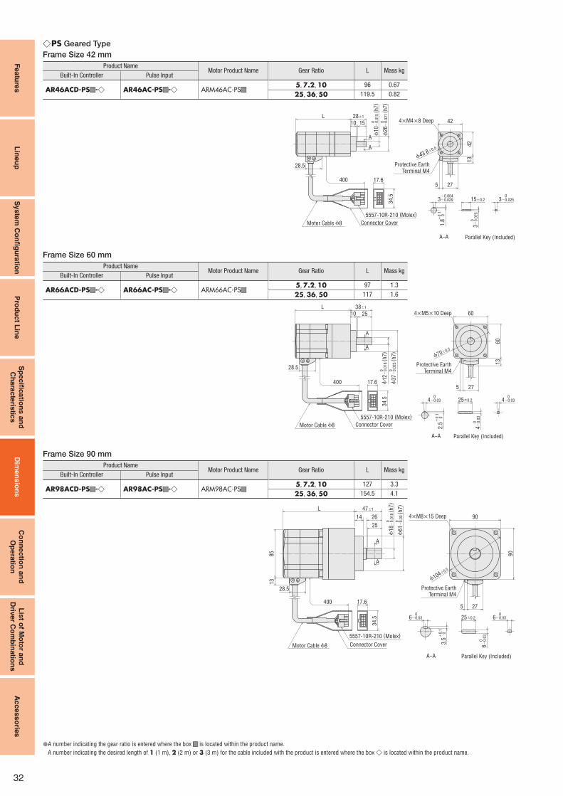
32
Featu
res
Lin
eu
pS
yste
m C
on
fi gu
ratio
nP
rod
uc
t Lin
eS
pe
cifi c
atio
ns
an
d
Ch
ara
cte
ristic
sD
ime
ns
ion
sC
on
nectio
n a
nd
Op
era
tion
Lis
t of M
oto
r an
d
Driv
er C
om
bin
atio
ns
Acces
so
ries
PS ◇ Geared Type
Frame Size 42 mm
Product NameMotor Product Name Gear Ratio L Mass kg
Built-In Controller Pulse Input
AR46ACD-PS ■ ■-◇ AR46AC-PS ■ ■-◇ ARM46AC-PS ■ ■5, 7.2, 10 96 0.67
25, 36, 50 119.5 0.82
400 17.6
34.5
5557-10R-210 (Molex)
L
13
ϕ10
−0.0
15 (
h7
)0
A
A
ϕ26
−0.0
21 (
h7
)010
28±1
15
1.8
0
+0.1
42
42
ϕ43.8±0.5
A−A
4×M4×8 Deep
15±0.2
3−
0.0
25
0
3−0.029−0.004
3−0.0250
5 27
Parallel Key (Included)
28.5 Protective EarthTerminal M4
Motor Cable ϕ8 Connector Cover
Frame Size 60 mm
Product NameMotor Product Name Gear Ratio L Mass kg
Built-In Controller Pulse Input
AR66ACD-PS ■ ■-◇ AR66AC-PS ■ ■-◇ ARM66AC-PS ■ ■5, 7.2, 10 97 1.3
25, 36, 50 117 1.6
400 17.63
4.5
5557-10R-210 (Molex)
ϕ1
2−
0.0
18 (
h7
)0
ϕ3
7−
0.0
25 (
h7
)0
A
A
L 38±1
28.5
2510
60
13
604×M5×10 Deep
ϕ70±0.5
5 27
4−0.03 0 0
4−0.03
4−
0.0
3 0
25±0.2
2.5
0
+0.1
A−A Parallel Key (Included)
Motor Cable ϕ8 Connector Cover
Protective EarthTerminal M4
Frame Size 90 mm
Product NameMotor Product Name Gear Ratio L Mass kg
Built-In Controller Pulse Input
AR98ACD-PS ■ ■-◇ AR98AC-PS ■ ■-◇ ARM98AC-PS ■ ■5, 7.2, 10 127 3.3
25, 36, 50 154.5 4.1
34.5
400 17.6
5557-10R-210 (Molex)
A
A
85
13
25
2614
L
28.5
47±1
ϕ6
1−
0.0
3 (
h7
)0
ϕ1
8−
0.0
18 (
h7
)0
90
90
275
4×M8×15 Deep
6−0.030
6−
0.0
30
25±0.2
3.5
0+0.1
6−0.030
ϕ104±0.5
A−A Parallel Key (Included)
Motor Cable ϕ8
Protective EarthTerminal M4
Connector Cover
A number indicating the gear ratio is entered where the box ● ■■ is located within the product name.
A number indicating the desired length of 1 (1 m), 2 (2 m) or 3 (3 m) for the cable included with the product is entered where the box ◇ is located within the product name.

Featu
res
Lin
eu
pS
yste
m C
on
fi gu
ratio
nP
rod
uc
t Lin
eS
pe
cifi c
atio
ns
an
d
Ch
ara
cte
ristic
sD
ime
ns
ion
sC
on
nectio
n a
nd
Op
era
tion
Lis
t of M
oto
r an
d
Driv
er C
om
bin
atio
ns
Acces
so
ries
33
PS ◇ Geared Type with Electromagnetic Brake
Frame Size 42 mm
Product NameMotor Product Name Gear Ratio L Mass kg
Built-In Controller Pulse Input
AR46MCD-PS ■ ■-◇ AR46MC-PS ■ ■-◇ ARM46MC-PS ■ ■5, 7.2, 10 125.5 0.82
25, 36, 50 149 0.97
16
18.5
17.6
34.54
00
400
5557-10R-210 (Molex)5557-02R-210 (Molex)
ϕ10
−0.0
15 (
h7
)0
A
A
ϕ26
−0.0
21 (
h7
)010
28±1
15
L
28.512 13
1.8
0
+0.1
42
42
ϕ43.8±0.5
15±0.2
3−
0.0
25
0
3−0.029−0.004
3−0.0250
5 27
4×M4×8 Deep
A−A Parallel Key (Included)
Motor Cable ϕ8 Connector CoverConnector Cover
Protective EarthTerminal M4
ElectromagneticBrake Cable ϕ6
Frame Size 60 mm
Product NameMotor Product Name Gear Ratio L Mass kg
Built-In Controller Pulse Input
AR66MCD-PS ■ ■-◇ AR66MC-PS ■ ■-◇ ARM66MC-PS ■ ■5, 7.2, 10 132 1.6
25, 36, 50 152 1.91
6
40
0
18.5
12 28.5
400 17.63
4.5
5557-10R-210 (Molex)5557-02R-210 (Molex)
ϕ1
2−
0.0
18 (
h7
)0
ϕ3
7−
0.0
25 (
h7
)0
2510L 38±1
A
A
60
13
60
ϕ70±0.5
5 27
4−0.03 0 0
4−0.03
4−
0.0
3 0
25±0.2
2.5
0
+0.1
4×M5×10 Deep
A−A Parallel Key (Included)
Protective EarthTerminal M4
Motor Cable ϕ8 Connector Cover
ElectromagneticBrake Cable ϕ6
Connector Cover
Frame Size 90 mm
Product NameMotor Product Name Gear Ratio L Mass kg
Built-In Controller Pulse Input
AR98MCD-PS ■ ■-◇ AR98MC-PS ■ ■-◇ ARM98MC-PS ■ ■5, 7.2, 10 169 3.9
25, 36, 50 196.5 4.7
16
40
0
18.5
5557-02R-210 (Molex)
34.5
400 17.6
5557-10R-210 (Molex)
A
A
85
13
L
28.512
ϕ6
1−
0.0
3 (
h7
)0
ϕ1
8−
0.0
18 (
h7
)0
25
2614
47±1
90
90
275
4×M8×15 Deep
ϕ104±0.5
6−0.030
6−
0.0
30
25±0.2
3.5
0+0.1
6−0.030
A−A Parallel Key (Included)
Protective EarthTerminal M4
Motor Cable ϕ8 Connector CoverConnector Cover
ElectromagneticBrake Cable ϕ6
A number indicating the gear ratio is entered where the box ● ■■ is located within the product name.
A number indicating the desired length of 1 (1 m), 2 (2 m) or 3 (3 m) for the cable included with the product is entered where the box ◇ is located within the product name.
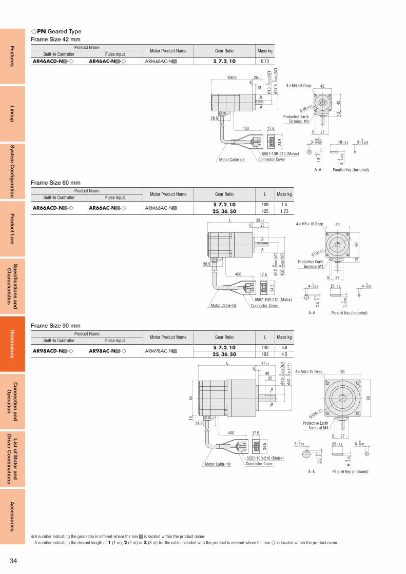
34
Featu
res
Lin
eu
pS
yste
m C
on
fi gu
ratio
nP
rod
uc
t Lin
eS
pe
cifi c
atio
ns
an
d
Ch
ara
cte
ristic
sD
ime
ns
ion
sC
on
nectio
n a
nd
Op
era
tion
Lis
t of M
oto
r an
d
Driv
er C
om
bin
atio
ns
Acces
so
ries
PN ◇ Geared Type
Frame Size 42 mm
Product NameMotor Product Name Gear Ratio Mass kg
Built-In Controller Pulse Input
AR46ACD-N ■ ■-◇ AR46AC-N ■ ■-◇ ARM46AC-N ■ ■ 5, 7.2, 10 0.73
4×M4×8 Deep
3−
0.0
25
0
3−0.025 0
42
42
28.5
5 27
A
A
18
6100.5
400 17.6
34.5
13
25±1
ϕ10
−0.0
15 (
h7
)0
ϕ37.6
−0.0
25 (
h7
)0
5557-10R-210 (Molex)
ϕ48±0.3
1.8
0
+0.1
3−0.029 −0.004
18±0.2
A−A Parallel Key (Included)
Protective EarthTerminal M4
Motor Cable ϕ8 Connector Cover
Frame Size 60 mm
Product NameMotor Product Name Gear Ratio L Mass kg
Built-In Controller Pulse Input
AR66ACD-N ■ ■-◇ AR66AC-N ■ ■-◇ ARM66AC-N ■ ■5, 7.2, 10 109 1.5
25, 36, 50 125 1.73
5 27
28.5
A
6 25 60
60
400 17.63
4.5
A
13
L
ϕ70±0.5
38±1
ϕ3
7−
0.0
25 (
h7
)0
ϕ1
2−
0.0
18 (
h7
)0
5557-10R-210 (Molex)
4−0.03 0
4−
0.0
3 0
4−0.03 0
25±0.2
2.5
0
+0.1
A−A Parallel Key (Included)
4×M5×10 Deep
Motor Cable ϕ8
Protective EarthTerminal M4
Connector Cover
Frame Size 90 mm
Product NameMotor Product Name Gear Ratio L Mass kg
Built-In Controller Pulse Input
AR98ACD-N ■ ■-◇ AR98AC-N ■ ■-◇ ARM98AC-N ■ ■5, 7.2, 10 140 3.8
25, 36, 50 163 4.5
A
A
909
0
25
40
6
85
13
L
34.5
400 17.6
28.5
275
4×M8×15 Deep
ϕ104±0.5
47±1
5557-10R-210 (Molex)
ϕ6
1−
0.0
3 (
h7
)0
ϕ1
8−
0.0
18 (
h7
)0
6−0.03 0
6−0.03 0
6−
0.0
3 0
25±0.2
Parallel Key (Included)
3.5
0
+0.1
A−A
Protective EarthTerminal M4
Motor Cable ϕ8 Connector Cover
A number indicating the gear ratio is entered where the box ● ■■ is located within the product name.
A number indicating the desired length of 1 (1 m), 2 (2 m) or 3 (3 m) for the cable included with the product is entered where the box ◇ is located within the product name.

Featu
res
Lin
eu
pS
yste
m C
on
fi gu
ratio
nP
rod
uc
t Lin
eS
pe
cifi c
atio
ns
an
d
Ch
ara
cte
ristic
sD
ime
ns
ion
sC
on
nectio
n a
nd
Op
era
tion
Lis
t of M
oto
r an
d
Driv
er C
om
bin
atio
ns
Acces
so
ries
35
PN ◇ Geared Type with Electromagnetic Brake
Frame Size 42 mm
Product NameMotor Product Name Gear Ratio Mass kg
Built-In Controller Pulse Input
AR46MCD-N ■ ■-◇ AR46MC-N ■ ■-◇ ARM46MC-N ■ ■ 5, 7.2, 10 0.88
A
A
16
18
642
42
18.5
130
12
17.6
34.5
28.5
5 27
400
400
13
25±1
ϕ10
−0.0
15 (
h7
)0
ϕ37.6
−0.0
25 (
h7
)0
ϕ48±0.3
5557-10R-210 (Molex)
3−
0.0
25
0
3−0.025 0
3−0.029 −0.004
18±0.2
5557-02R-210 (Molex)
1.8
0
+0.1
4×M4×8 Deep
A−A Parallel Key (Included)
Motor Cable ϕ8
Protective EarthTerminal M4
Connector CoverConnector Cover
ElectromagneticBrake Cable ϕ6
Frame Size 60 mm
Product NameMotor Product Name Gear Ratio L Mass kg
Built-In Controller Pulse Input
AR66MCD-N ■ ■-◇ AR66MC-N ■ ■-◇ ARM66MC-N ■ ■5, 7.2, 10 144 1.8
25, 36, 50 160 2
60
A
A
16
256L
5 27
40
0
18.5
12
60
13
28.5
400 17.63
4.5
38±1
5557-10R-210 (Molex)5557-02R-210 (Molex)
ϕ1
2−
0.0
18 (
h7
)0
ϕ3
7−
0.0
25 (
h7
)0
ϕ70±0.5
4−0.03 0
4−
0.0
3 0
4−0.03 0
25±0.2
Parallel Key (Included)A−A2
.5
0 +
0.1
4×M5×10 Deep
Motor Cable ϕ8
Protective EarthTerminal M4
Connector CoverConnector Cover
ElectromagneticBrake Cable ϕ6
Frame Size 90 mm
Product NameMotor Product Name Gear Ratio L Mass kg
Built-In Controller Pulse Input
AR98MCD-N ■ ■-◇ AR98MC-N ■ ■-◇ ARM98MC-N ■ ■5, 7.2, 10 182 4.4
25, 36, 50 205 5.1
A
A
85
13
16
90
90
25
40
6
L
275400
28.5
34
.5
17.6
40
0
12
18.5
47±1
5557-02R-210 (Molex)5557-10R-210 (Molex)
ϕ6
1−
0.0
3 (
h7
)0
ϕ1
8−
0.0
18 (
h7
)0
4×M8×15 Deep
ϕ104±0.5
6−0.03 0
6−0.03 0
6−
0.0
3 0
25±0.2
3.5
0
+0.1
A−A Parallel Key (Included)
Protective EarthTerminal M4
Connector CoverMotor Cable ϕ8Connector Cover
ElectromagneticBrake Cable ϕ6
A number indicating the gear ratio is entered where the box ● ■■ is located within the product name.
A number indicating the desired length of 1 (1 m), 2 (2 m) or 3 (3 m) for the cable included with the product is entered where the box ◇ is located within the product name.
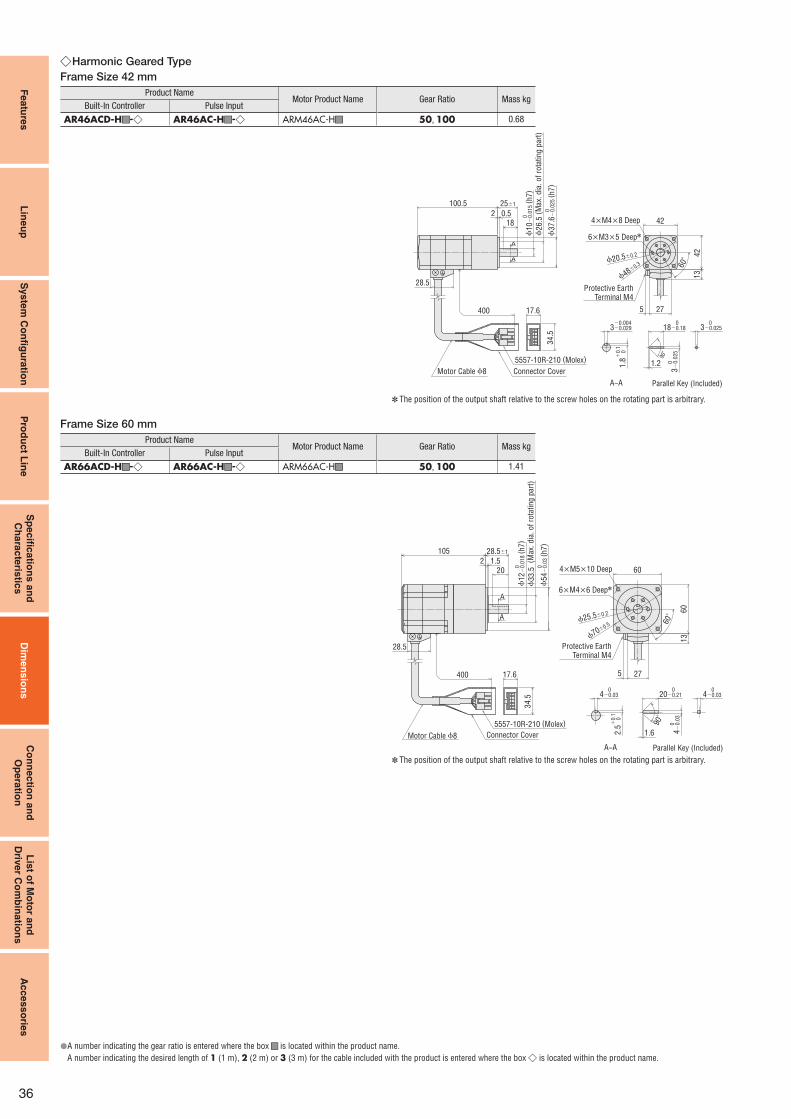
36
Featu
res
Lin
eu
pS
yste
m C
on
fi gu
ratio
nP
rod
uc
t Lin
eS
pe
cifi c
atio
ns
an
d
Ch
ara
cte
ristic
sD
ime
ns
ion
sC
on
ne
ctio
n a
nd
Op
era
tion
Lis
t of M
oto
r an
d
Driv
er C
om
bin
atio
ns
Acces
so
ries
Harmonic Geared Type ◇Frame Size 42 mm
Product NameMotor Product Name Gear Ratio Mass kg
Built-In Controller Pulse Input
AR46ACD-H ■ ■-◇ AR46AC-H ■ ■-◇ ARM46AC-H ■ ■ 50, 100 0.68
25±1
1.2
42
42
28.5
ϕ26.5
(M
ax. dia
. of
rota
ting p
art)
180.52
5 27
A
A
100.5
400 17.6
34.5
13
4×M4×8 Deep
6×M3×5 Deep✽
ϕ20.5±0.2
ϕ48±0.3 60˚
90˚
ϕ10
−0.0
15 (
h7
)0
ϕ37.6
−0.0
25 (
h7
)0
5557-10R-210 (Molex)
3−
0.0
25
0
3−0.025 0
3−0.029 −0.004
18−0.18
1.8
0
+0.1
0
A−A Parallel Key (Included)
Motor Cable ϕ8 Connector Cover
Protective EarthTerminal M4
The position of the output shaft relative to the screw holes on the rotating part is arbitrary. ✽
Frame Size 60 mm
Product NameMotor Product Name Gear Ratio Mass kg
Built-In Controller Pulse Input
AR66ACD-H ■ ■-◇ AR66AC-H ■ ■-◇ ARM66AC-H ■ ■ 50, 100 1.41
5557-10R-210 (Molex)
60˚
90˚
5 27
ϕ33.5
(M
ax. d
ia. o
f ro
tati
ng
par
t)
28.5
A
A
201.52
60
60
400 17.6
34
.5
1.6
13
105 28.5±1
ϕ5
4−
0.0
3 (
h7
)0
ϕ1
2−
0.0
18 (
h7
)0
ϕ70±0.5ϕ25.5±0.2
4×M5×10 Deep
4−0.03 0
4−0.03 0
4−
0.0
3 0
2.5
0
+0.1
20−0.21 0
A−A Parallel Key (Included)
6×M4×6 Deep✽
Motor Cable ϕ8 Connector Cover
Protective EarthTerminal M4
The position of the output shaft relative to the screw holes on the rotating part is arbitrary. ✽
A number indicating the gear ratio is entered where the box ● ■■ is located within the product name.
A number indicating the desired length of 1 (1 m), 2 (2 m) or 3 (3 m) for the cable included with the product is entered where the box ◇ is located within the product name.
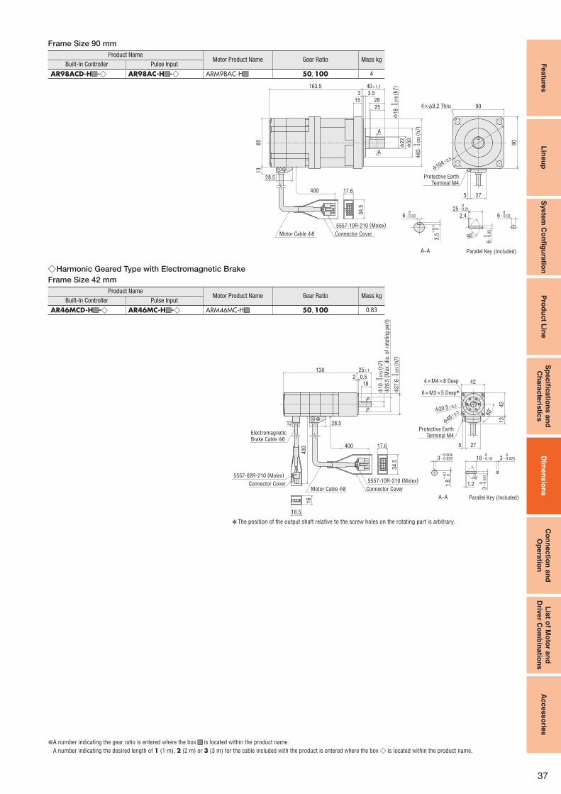
Featu
res
Lin
eu
pS
yste
m C
on
fi gu
ratio
nP
rod
uc
t Lin
eS
pe
cifi c
atio
ns
an
d
Ch
ara
cte
ristic
sD
ime
ns
ion
sC
on
ne
ctio
n a
nd
Op
era
tion
Lis
t of M
oto
r an
d
Driv
er C
om
bin
atio
ns
Ac
cess
orie
s
37
Frame Size 90 mm
Product NameMotor Product Name Gear Ratio Mass kg
Built-In Controller Pulse Input
AR98ACD-H ■ ■-◇ AR98AC-H ■ ■-◇ ARM98AC-H ■ ■ 50, 100 4
2.4
A
A
25
15
3 3.5
90
9085
13
275
28
163.5
34.5
400 17.6
28.5
5557-10R-210 (Molex)
40±1.2
4×ϕ9.2 Thru
ϕ104±0.5
ϕ83
−0.0
35 (
h7
)0
ϕ18
−0.0
18 (
h7
)0
ϕ50
ϕ22
6−0.03 0
6−0.03 0
6−
0.0
3 03.5
0
+0.1
25−0.21 0
90˚
Parallel Key (Included)A−A
Protective EarthTerminal M4
Motor Cable ϕ8 Connector Cover
Harmonic Geared Type with Electromagnetic Brake ◇Frame Size 42 mm
Product NameMotor Product Name Gear Ratio Mass kg
Built-In Controller Pulse Input
AR46MCD-H ■ ■-◇ AR46MC-H ■ ■-◇ ARM46MC-H ■ ■ 50, 100 0.83
A
A
16
2 0.5
18
18.5
42
42
130
5 27
12
17.6
34
.5
28.5 13
40
0 400
25±1
ϕ2
6.5
(M
ax. d
ia. o
f ro
tati
ng
par
t)
ϕ1
0−
0.0
15 (
h7
)0
ϕ3
7.6
−0.0
25 (
h7
)0
ElectromagneticBrake Cable ϕ6
5557-02R-210 (Molex)5557-10R-210 (Molex)
60˚
4×M4×8 Deep
6×M3×5 Deep✽
ϕ20.5±0.2
ϕ48±0.3
1.2
90˚
3−
0.0
25
0
3−0.025 0
3−0.029 −0.004
18−0.18
1.8
0
+0.1
0
A−A Parallel Key (Included)
Motor Cable ϕ8 Connector Cover
Protective EarthTerminal M4
Connector Cover
The position of the output shaft relative to the screw holes on the rotating part is arbitrary. ✽
A number indicating the gear ratio is entered where the box ● ■■ is located within the product name.
A number indicating the desired length of 1 (1 m), 2 (2 m) or 3 (3 m) for the cable included with the product is entered where the box ◇ is located within the product name.

38
Featu
res
Lin
eu
pS
yste
m C
on
fi gu
ratio
nP
rod
uc
t Lin
eS
pe
cifi c
atio
ns
an
d
Ch
ara
cte
ristic
sD
ime
ns
ion
sC
on
nectio
n a
nd
Op
era
tion
Lis
t of M
oto
r an
d
Driv
er C
om
bin
atio
ns
Acces
so
ries
Frame Size 60 mm
Product NameMotor Product Name Gear Ratio Mass kg
Built-In Controller Pulse Input
AR66MCD-H ■ ■-◇ AR66M C-H ■ ■-◇ ARM66MC-H ■ ■ 50, 100 1.71
A
A
16
140
201.52
400
18.5
12 28.5
400 17.6
34.5
5 27
60
60
13
28.5±1
ElectromagneticBrake Cable ϕ6
5557-02R-210 (Molex)5557-10R-210 (Molex) 90
˚
1.6
4−0.03 0
4−0.03 0
4−
0.0
3 0
2.5
0
+0.1
20−0.21 0
Parallel Key (Included)A−A
6×M4×6 Deep✽
ϕ70±0.5ϕ25.5±0.2
60˚
ϕ33.5
(M
ax. dia
. of
rota
ting p
art)
ϕ54
−0.0
3 (
h7
)0
ϕ12
−0.0
18 (
h7
)0 4×M5×10 Deep
Protective EarthTerminal M4
Motor Cable ϕ8 Connector CoverConnector Cover
The position of the output shaft relative to the screw holes on the rotating part is arbitrary. ✽
Frame Size 90 mm
Product NameMotor Product Name Gear Ratio Mass kg
Built-In Controller Pulse Input
AR98MCD-H ■ ■-◇ AR98MC-H ■ ■-◇ ARM98MC-H ■ ■ 50, 100 4.6
A
A
85
13
16
9028
90
205.5
275400
28.5
34
.5
17.6
40
0
12
18.5
25
15
3 3.5
40±1.2
5557-02R-210 (Molex)5557-10R-210 (Molex)
ϕ8
3−
0.0
35 (
h7
)0ϕ5
0
ϕ2
2
ϕ1
8−
0.0
18 (
h7
)0 4×ϕ9.2 Thru
ϕ104±0.5
2.46−0.03 0
6−0.03 0
6−
0.0
3 03.5
0
+0.1
25−0.21 0
90˚
Parallel Key (Included)A−A
ElectromagneticBrake Cable ϕ6
Protective EarthTerminal M4
Motor Cable ϕ8 Connector CoverConnector Cover
A number indicating the gear ratio is entered where the box ● ■■ is located within the product name.
A number indicating the desired length of 1 (1 m), 2 (2 m) or 3 (3 m) for the cable included with the product is entered where the box ◇ is located within the product name.

Featu
res
Lin
eu
pS
yste
m C
on
fi gu
ratio
nP
rod
uc
t Lin
eS
pe
cifi c
atio
ns
an
d
Ch
ara
cte
ristic
sD
ime
ns
ion
sC
on
nectio
n a
nd
Op
era
tion
Lis
t of M
oto
r an
d
Driv
er C
om
bin
atio
ns
Acces
so
ries
39
Drivers ●Built-In Controller Package ◇
Mass: 0.75 kg
Slits
17.5
8.1
10
ϕ4.5 Thru
5
5150
35
12537 max.45
2×M4
160
Slits
Accessories●Connector for Power Input Terminal (CN1)
Connector: MC1,5/6-STF-3,5 (PHOENIX CONTACT GmbH & Co. KG)
Connector for Sensor Signal (CN5)
Connector: FK-MC0,5/5-ST-2,5 (PHOENIX CONTACT GmbH & Co. KG)
Connector for Input Signal (CN8)
Connector: FK-MC0,5/9-ST-2,5 (PHOENIX CONTACT GmbH & Co. KG)
Connector for Output Signal (CN9)
Connector: FK-MC0,5/7-ST-2,5 (PHOENIX CONTACT GmbH & Co. KG)
Connector for Regeneration Unit/Main Power Supply (CN3)
Connector: 54928-0570 (Molex)
Pulse Input Package ◇Mass: 0.75 kg
Slits
17.5
8.1
10
ϕ4.5 Thru
5
5150
35
12541 max.45
2×M4
160
Accessories●Connector for Control I/O (CN5)
Cover Assembly: 10336-52A0-008 (Sumitomo 3M Limited)
Connector: 10136-3000PE (Sumitomo 3M Limited)
Connector for Regeneration Unit Input/Main Power Supply Input Terminal (CN3)
Connector: 54928-0570 (Molex)
Connector for 24 VDC Power Supply Input/Regeneration Unit Thermal
Input/Electromagnetic Brake Output Terminal (CN1)
Connector: MC1,5/6-STF-3,5
(PHOENIX CONTACT GmbH & Co. KG)
Cable for Motor (Included), Cable for Electromagnetic Brake (Included) ●Common to All Types
Cable for Motor ●Cable Type Length L (m)
Cable for Motor 1 m 1
Cable for Motor 2 m 2
Cable for Motor 3 m 35557-10R-210(Molex)
12
22.2
14.5
37.5
11.619.6
20.6
Motor Side Driver Side
30
24.3
23.9ϕ8
L
75
5559-10P-210(Molex) Connector Cover
Cable for Electromagnetic Brake ●(Only for electromagnetic brake type)
Cable Type Length L (m)
Cable for Motor 1 m 1
Cable for Motor 2 m 2
Cable for Motor 3 m 3
13.5
19
11.8 80±10
24L
ϕ4.1
Driver SideMotor Side
Stick Terminal: AI0.5-8WH(PHOENIX CONTACT GmbH & Co. KG)
Connector Cover
76
21.5
5559-02P-210(Molex)

40
Featu
res
Lin
eu
pS
yste
m C
on
fi gu
ratio
nP
rod
uc
t Lin
eS
pe
cifi c
atio
ns
an
d
Ch
ara
cte
ristic
sD
ime
ns
ion
sC
on
nectio
n a
nd
Op
era
tion
Lis
t of M
oto
r an
d
Driv
er C
om
bin
atio
ns
Ac
cess
orie
s
Connection and Operation (Built-In Controller Package) ■
Names and Functions of Driver Parts ●
Not used (CN10)
Baud Rate Setting Switch (SW2)
Function Setting Switches (SW4)
Address Number Setting Switch (ID)
RS-485 Communication Connector (CN6)
Output Signal Connector (CN9)
Input Signal Connector (CN8)
Sensor Signal Connector (CN5)
24 VDC Power Supply Input Terminal (CN1)
Signal Monitor Displays
RS-485 Communication Connector (CN7)
Regeneration Unit Thermal Input Terminal (CN1)
Electromagnetic Brake Terminal (CN1)
Motor Connector (CN2)
CHARGE
Regeneration Unit Connection Terminal (CN3)
Main Power Supply Input Terminal (CN3)
Protective Earth Terminal
Control Module Connector (CN4)
Termination Resister Setting Switches (TERM.)
Bottom of the Driver
Signal Monitor Displays
LED Indicators ◇Indication Color Function When Activated
PWR Green Power Supply Indication Lights when 24 VDC power is on.
ALM Red Alarm Indication Blinks when protective functions are activated.
C-DAT Green Communication Indication Blinks or illuminate when communication data is received or sent.
C-ERR Red Communication Error Indication Illuminates when there is an error with communication data.
Address Number Setting Switch (ID)
Indication Switch Name Function
ID Address Number Setting Switch Set the address number for RS-485 communication (Factory Setting: 0).
Baud Rate Setting Switch (SW2)
Indication Switch Name Function
SW2 Baud Rate Setting Switch Set the baud rate for RS-485 communications (Factory Setting: 7).
Setting the Baud Rate for RS-484 Communications ◇No. Baud Rate (bps)
0 9600
1 19200
2 38400
3 57600
4 115200
5∼6 Not used
7 Factory setting
8∼F Not used

Featu
res
Lin
eu
pS
yste
m C
on
fi gu
ratio
nP
rod
uc
t Lin
eS
pe
cifi c
atio
ns
an
d
Ch
ara
cte
ristic
sD
ime
ns
ion
sC
on
nectio
n a
nd
Op
era
tion
Lis
t of M
oto
r an
d
Driv
er C
om
bin
atio
ns
Ac
cess
orie
s
41
Termination Resister Setting Switches (TERM.)
Indication No. Function
TERM.1 Set the termination resister (120 Ω) for RS-485 communication (Factory setting: OFF).
OFF: No termination resister ON: Set the termination resister2
Please use the same settings for both No. 1 and No. 2.✽
Function Setting Switches (SW4)
Indication No. Function
SW41 This sets the address number in combination with the address number setting switch (ID) (Factory setting: OFF).
2 This sets the protocol for RS-485 communication (Factory setting: OFF).
RS-485 Communication Protocol Setting ◇Destination
No.– Modbus RTU Mode
2 OFF ON
Input Signal Connector (CN8)
Indication Pin No. Signal Name Initial Value
CN8
1 IN0 HOME This performs the return-to-home operation.
2 IN1 START This performs the positioning operation.
3 IN2 M0
The operating data number is selected using 3 bits. 4 IN3 M1
5 IN4 M2
6 IN5 FREE Stop motor excitation and release the electromagnetic brake.
7 IN6 STOP This stops the motor.
8 IN7 ALM-RST This resets the current alarm.
Assigned functions are set by means of the parameter settings. The above is the initial value. For details, refer to the User’s Manual. ✽
The following input signals can be assigned to input terminals IN0∼7.
Input Signal
0: Not used 5: SSTART 10: MS2 17: C-ON 27: HMI 36: R4 41: R9 46: R14 51: M3
1: FWD 6: +JOG 11: MS3 18: STOP 32: R0 37: R5 42: R10 47: R15 52: M4
2: RVS 7: −JOG 12: MS4 24: ALM-RST 33: R1 38: R6 43: R11 48: M0 53: M5
3: HOME 8: MS0 13: MS5 25: P-PRESET 34: R2 39: R7 44: R12 49: M1
4: START 9: MS1 16: FREE 26: P-CLR 35: R3 40: R8 45: R13 50: M2
Output Signal Connector (CN9)
Indication Pin No. Signal Name Initial Value
CN9
1 OUT0 HOME-P Output when the motor is home.
2 OUT1 END Output when the positioning operation has finished.
3 OUT2 AREA1 Output when the motor is in area 1.
4 OUT3 READY Output when driver operation preparations have finished.
5 OUT4 WNG The driver's warning status is output.
6 OUT5 ALM The driver's alarm status is output (normally closed).
Assigned functions are set by means of the parameter settings. The above is the initial value. For details, refer to the User’s Manual. ✽
The following output signals can be assigned to output terminals OUT0∼5.
Output Signal
0: Not used 7: −JOG_R 16: FREE_R 36: R4 43: R11 50: M2_R 63: SLIT_R 71: TLC
1: FWD_R 8: MS0_R 17: C-ON_R 37: R5 44: R12 51: M3_R 65: ALM 72: TIM
2: RVS_R 9: MS1_R 18: STOP_R 38: R6 45: R13 52: M4_R 66: WNG 73: AREA1
3: HOME_R 10: MS2_R 32: R0 39: R7 46: R14 53: M5_R 67: READY 74: AREA2
4: START_R 11: MS3_R 33: R1 40: R8 47: R15 60: +LS_R 68: MOVE 75: AREA3
5: SSTART_R 12: MS4_R 34: R2 41: R9 48: M0_R 61: −LS_R 69: END 80: S-BSY
6: +JOG_R 13: MS5_R 35: R3 42: R10 49: M1_R 62: HOMES_R 70: HOME-P 82: MPS
Sensor Signal Connector (CN5)
Indication Pin No. Signal Name Initial Value
CN5
1 +LS +Side Limit Sensor Input
2 −LS −Side Limit Sensor Input
3 HOMES Mechanical Home Sensor Input
4 SLIT Slit Sensor Input
5 IN-COM2 Common for Sensor
24 VDC Input/Regeneration Unit Thermal Input/Electromagnetic Brake Connction Terminal (CN1)
Indication I/O Terminal Name Content
24V+
Input
24 VDC Power Input Terminal+This is the power supply for the driver's control circuit terminal. Always connect when using.
24V− 24 VDC Power Input Terminal−
TH1 Regeneration Unit Thermal Input Terminal Connects the accessory regeneration unit RGB100 (sold separately).
Short circuit between the terminals when no regeneration unit is connected. TH2 Regeneration Unit Thermal Input Terminal
MB1Output
Electromagnetic Brake Connection Terminal−This connects the electromagnetic brake line of an electromagnetic brake type motor.
MB2 Electromagnetic Brake Connection Terminal+

42
Featu
res
Lin
eu
pS
yste
m C
on
fi gu
ratio
nP
rod
uc
t Lin
eS
pe
cifi c
atio
ns
an
d
Ch
ara
cte
ristic
sD
ime
ns
ion
sC
on
ne
ctio
n a
nd
Op
era
tion
Lis
t of M
oto
r an
d
Driv
er C
om
bin
atio
ns
Acce
sso
ries
Connection Diagram ●Connection to Peripheral Equipment ◇
or
Data Setting Software (MEXE02)
Output Signal: Connect to CN9.
Motor
Power Supply Voltage
Single-Phase 200-240 VAC 50/60 Hz
Circuit Breaker or
Ground Fault
Interrupt Circuit✽2
Noise Filter✽2
Connect to CN1.
Connect to CN2.
Controller✽2
GND
Input Signal: Connect to CN8.
Sensor Signal: Connect to CN5.
Thermostat Output
[AWG22 (0.3 mm2)]
2 Leads
Regeneration Unit (RGB100)
Driver
Regeneration Unit
[AWG18 (0.75 mm2)]
2 Leads
Included in the product.
Available as accessories (sold separately).
Motor Cable (Included)✽1 24 VDC
24 VDC Power Supply✽2
Always connect when using.
Control Module (OPX-2A)
1 Each model comes with a motor cable 1, 2 or 3 m long. If you need a cable of a different length or a flexible cable, select an appropriate cable from among the accessories (sold separately).✽
Keep the wiring distance between the motor and driver to 30 m max.
2✽ Not supplied.
Connecting a Main Power Supply ◇Use the following cable for the power supply line;
3-core cable of AWG16 to 14 (1.25 to 2.0 mm2)
Single-Phase
200-240 VAC 50/60 Hz
CN3 ConnectorDriver
Connect to
CN3 of the
driver.
Connecting the Control Power Supply ◇Provide a 24 VDC power supply.
−+
AWG28∼16
(0.08∼1.25 mm2)
24 VDC ±5%
0.5 A min.
CN1 Connector
24 VDC
Power Supply
Motor Cable
Connect to CN2.
Cable for Motor
(Included)
24 V+24 V−
Connecting the Electromagnetic Brake ◇
Cable for Motor
(Included)
Cable for Electromagnetic Brake (Included)
−+
MB1MB2
AWG28∼16
(0.08∼1.25 mm2)
Motor Cable
Electromagnetic
Brake Cable
Black
White
24 VDC ±5%✽
0.75 A min.
24 VDC
Power SupplyCN1 Connector
Connect to CN1.
Connect to CN2.
24 V+24 V−
If the distance between the motor and driver is extended to 20 m or longer, use a power supply ✽
of 24 VDC ±4%.
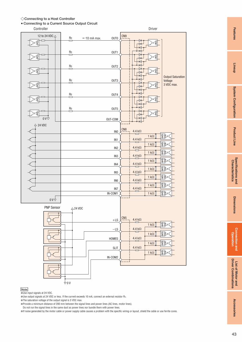
Featu
res
Lin
eu
pS
yste
m C
on
fi gu
ratio
nP
rod
uc
t Lin
eS
pe
cifi c
atio
ns
an
d
Ch
ara
cte
ristic
sD
ime
ns
ion
sC
on
ne
ctio
n a
nd
Op
era
tion
Lis
t of M
oto
r an
d
Driv
er C
om
bin
atio
ns
Acces
so
ries
43
Connecting to a Host Controller ◇Connecting to a Current Source Output Circuit ●
←10 mA max. OUT0CN9
IN0
IN1
IN2
IN3
IN4
IN-COM1
IN7
IN6
IN5
CN8
+LS
−LS
HOMES
SLIT
IN-COM2
CN5
OUT1
OUT2
OUT3
OUT4
OUT5
OUT-COM
4.4 kΩ
4.4 kΩ1 kΩ
1 kΩ
1 kΩ
1 kΩ
1 kΩ
1 kΩ
1 kΩ
1 kΩ
4.4 kΩ
4.4 kΩ
4.4 kΩ
4.4 kΩ
4.4 kΩ
4.4 kΩ
1 kΩ
1 kΩ
1 kΩ
1 kΩ
4.4 kΩ
4.4 kΩ
4.4 kΩ
4.4 kΩ
R0
R0
R0
R0
R0
R0
0 V
0 V
0 V
12 to 24 VDC
Output Saturation
Voltage
3 VDC max.
24 VDC
24 VDC
DriverController
PNP Sensor
Note
Use input signals at 24 VDC.●Use output signals at 24 VDC or less. If the current exceeds 10 mA, connect an external resistor R● 0.
The saturation voltage of the output signal is 3 VDC max.●Provide a minimum distance of 200 mm between the signal lines and power lines (AC lines, motor lines).●Do not run the signal lines in the same duct as power lines nor bundle them with power lines.
If noise generated by the motor cable or power supply cable causes a problem with the specific wiring or layout, shield the cable or use ferrite cores.●

44
Featu
res
Lin
eu
pS
yste
m C
on
fi gu
ratio
nP
rod
uc
t Lin
eS
pe
cifi c
atio
ns
an
d
Ch
ara
cte
ristic
sD
ime
ns
ion
sC
on
nectio
n a
nd
Op
era
tion
Lis
t of M
oto
r an
d
Driv
er C
om
bin
atio
ns
Ac
cess
orie
s
Connecting to a Host Controller ◇Connecting to a Current Sink Output Circuit ●
24 VDC
12 to 24 VDC
10 mA max.→ OUT0CN9
IN0
IN1
IN2
IN3
IN4
IN-COM1
IN7
IN6
IN5
CN8
+LS
−LS
HOMES
SLIT
IN-COM2
CN5
OUT1
OUT2
OUT3
OUT4
OUT5
OUT-COM
4.4 kΩ
4.4 kΩ1 kΩ
1 kΩ
1 kΩ
1 kΩ
1 kΩ
1 kΩ
1 kΩ
1 kΩ
4.4 kΩ
4.4 kΩ
4.4 kΩ
4.4 kΩ
4.4 kΩ
4.4 kΩ
1 kΩ
1 kΩ
1 kΩ
1 kΩ
4.4 kΩ
4.4 kΩ
4.4 kΩ
4.4 kΩ
R0
R0
R0
R0
R0
R0
24 VDC
0 V
0 V
0 V
Output Saturation
Voltage
3 VDC max.
DriverController
NPN Sensor
Note
Use input signals at 24 VDC.●Use output signals at 24 VDC or less. If the current exceeds 10 mA, connect an external resistor R● 0.
The saturation voltage of the output signal is 3 VDC max.●Provide a minimum distance of 200 mm between the signal lines and power lines (AC lines, motor lines).●Do not run the signal lines in the same duct as power lines nor bundle them with power lines.
If noise generated by the motor cable or power supply cable causes a problem with the specific wiring or layout, shield the cable or use ferrite cores.●

Featu
res
Lin
eu
pS
yste
m C
on
fi gu
ratio
nP
rod
uc
t Lin
eS
pe
cifi c
atio
ns
an
d
Ch
ara
cte
ristic
sD
ime
ns
ion
sC
on
nectio
n a
nd
Op
era
tion
Lis
t of M
oto
r an
d
Driv
er C
om
bin
atio
ns
Ac
cess
orie
s
45
Connection and Operation (Pulse Input Package) ■
Names and Functions of Driver Parts ●
□1 Signal Monitor Displays
LED Displays ◇Indication Color Function When Activated
POWER Green Power supply indication Lights when main power or 24 VDC power is on.
ALARM Red Alarm indication Blinks when protective functions are activated.
CHARGE Red Power supply indication Lights when main power is on.
Alarms ◇Blink Count Function When Activated
2
Overheat The temperature inside the driver rises above 85°C.
OverloadWhen the amount of time during which the load torque exceeded the maximum torque exceeds the overload detection time. (Default
value: 5 seconds)
Overspeed The motor output shaft speed exceeds 4500 r/min.
Command pulse error The command pulse value becomes abnormal.
Regeneration unit overheat The thermostat for regeneration unit signal is activated.
3
Overvoltage The primary voltage of the driver's inverter exceeds the upper limit.
Main power supply error The main power is cut off when an operation command is input.
Undervoltage The primary voltage of the driver's inverter drops below the lower limit.
4
Overflow rotation during current on The position deviation exceeds the overflow revolutions. (Default value: 3 revolutions)
Overflow rotation during current offThe current is turned on even though the position deviation when the current is turned off was equal to or greater than the
permissible value. (Default value: 100 revolutions or more)
5Overcurrent An excessive current flows through the inverter power element inside the driver.
Drive circuit error The power cable of the motor is disconnected.
7Abnormal operation data Return to electrical home operation is performed while an operation data error warning is present.
Electronic gear setting error The resolution set by the electronic gear is outside the specified range.
8
Sensor error during operation A sensor error occurs while the motor is rotating.
Initial sensor error The power source is turned on when the motor cable is not connected to the driver.
Initial rotor rotation error The main power is turned on while the motor is rotating.
Motor combination error A motor not supported by the driver is connected.
9 EEPROM error A motor control parameter is damaged.
□2 Current Setting Switch
Indication Switch Name Function
CURRENT Current setting switchThis switch adjusts the operating current. It is used to limit the torque and temperature rise.
A desired current can be set as a percentage (%) of the rated output current. The factory setting is "F."
□3 Velocity Filter Setting Switch
Indication Switch Name Function
V-FIL Velocity filter setting switch
This switch adjusts the motor response.
Adjust the switch if you want to suppress motor vibration or cause the motor to
start/stop smoothly.
"0" and "F" correspond to the minimum and maximum velocity filter settings,
respectively.
The factory setting is "1."
Time
Moto
r S
pee
d
The difference in characteristics mode by the velocity filter
Set to "0"
Set to "F"
Motor Connector (CN2)
Regeneration Unit Terminal (CN3)
Main Power Supply Input Terminal (CN3)
Signal Monitor Display
Protective Earth Terminal
Control Module Connector (CN4)
I/O Signal Connector (CN5)
Function Select/Setting Switches
Velocity Filter Setting Switch
Current Setting Switch
Signal Monitor Displays24 VDC Power Supply Input Terminal (CN1)
Regeneration Unit Thermal Input Terminal (CN1)
Electromagnetic Brake Terminal (CN1)
□5
□1
□1
□2
□3
□4
□6

46
Featu
res
Lin
eu
pS
yste
m C
on
fi gu
ratio
nP
rod
uc
t Lin
eS
pe
cifi c
atio
ns
an
d
Ch
ara
cte
ristic
sD
ime
ns
ion
sC
on
nectio
n a
nd
Op
era
tion
Lis
t of M
oto
r an
d
Driv
er C
om
bin
atio
ns
Ac
cess
orie
s
□4 Function Select/Setting Switches
Indication Switch Name Function
D0/D1
Resolution select switches
These switches are used to set the resolution per rotation of the motor output shaft.
"D0" "CS0"➝1000 pulse <0.36°/step> [Factory setting]
"D0" "CS1"➝10000 pulse <0.036°/step>
"D1" "CS0"➝500 pulse <0.72°/step>
"D1" "CS1"➝5000 pulse <0.072°/step>CS0/CS1
NORM/CCM Control mode select switches
This switch toggles the driver between the normal mode and current control mode. In the current control mode, noise and vibration
can be reduced although the motor synchronicity may reduce.
"NORM": Normal mode [Factory setting]
"CCM": Current control mode
2P/1P Pulse input mode switchThe settings of this switch are compatible with the following two types of pulse input modes:
"1P" for the 1-pulse input mode [Factory setting], "2P" for the 2-pulse input mode.
□5 24 VDC Power Supply Input/Regeneration Unit Thermal Input/Electromagnetic Brake Terminal (CN1)
Indication Input/Output Terminal Name Description
24V+
Input
24 VDC power supply input terminal+ Connect a power supply to these terminals if you want to supply the control power separately from the main power.
Supply of the control power is optional. If you are using an electromagnetic brake motor, connect a power supply to
these terminals for the electromagnetic brake power.24V− 24 VDC power supply input terminal−
TH1 Regeneration unit thermal input terminal Connect the accessory regeneration unit RGB100 (sold separately).
If no regeneration unit is used, short the TH1 and TH2 terminals of CN1.TH2 Regeneration unit thermal input terminal
MB1Output
Electromagnetic brake terminal−Connect the lead wires from the electromagnetic brake.
MB2 Electromagnetic brake terminal+
□6 I/O Signal Connector (CN5, 36 pins)
Indication Input/Output Pin No.Signal Signal Name
Positioning Operation Push-Motion Operation✽1 Positioning Operation Push-Motion Operation✽1
CN5
− 1 – –
Output
2 GND Ground connection
3 ASG+A-phase pulse output (line driver)
4 ASG−
5 BSG+B-phase pulse output (line driver)
6 BSG−
7 TIM1+Timing output (line driver)
8 TIM1−
9 ALM+Alarm output
10 ALM−
11 WNG+Warning output
12 WNG−
13 END+Positioning complete output
14 END−
15 READY+/AL0+✽1Operation ready complete output/Alarm code output 0✽1
16 READY−/AL0−✽1
17 TLC+/AL1+✽1Torque limit output /Alarm code output 1✽1
18 TLC−/AL1−✽1
19 TIM2+/AL2+✽1Timing output (open-collector)/Alarm code output 2✽1
20 TIM2−/AL2−✽1
21 GND Ground connection
Input
22 IN–COM Input signal common
23 C–ON✽2 Current on input✽2
24 CLR/ALM–RST Deviation counter clear input/Alarm reset input
25 CCM Current control mode ON input
26 CS T–MODE✽1 Resolution select input Push-motion operation ON✽1
27 – M0✽1 –
Push-current setting select input✽128 RETURN M1✽1 Return to electrical home operation
29 P–RESET M2✽1 Position reset input
30 FREE Electromagnetic brake release, excitation OFF
31 PLS+/CW+Pulse input/CW pulse input (+5 V/line driver)
32 PLS−/CW−
33 PLS+24/CW+24V Pulse input/CW pulse input (+24 V)
34 DIR+24/CCW+24V Direction input/CCW pulse input (+24 V)
35 DIR+/CCW+Direction input/CCW pulse input (+5 V/line driver)
36 DIR−/CCW−
1 The signal will become effective if the applicable setting has been changed using the accessory control module ✽ OPX-2A or the data setting software MEXE02 (both sold separately).
2 The factory setting of the C-ON input is normally open. Be sure to turn the C-ON input ON when operating the motor. Set the C-ON input to normally close with a control module (✽ OPX-2A,
sold separately) or a data setting software (MEXE02, sold separately) when the C-ON input is not used.

Featu
res
Lin
eu
pS
yste
m C
on
fi gu
ratio
nP
rod
uc
t Lin
eS
pe
cifi c
atio
ns
an
d
Ch
ara
cte
ristic
sD
ime
ns
ion
sC
on
nectio
n a
nd
Op
era
tion
Lis
t of M
oto
r an
d
Driv
er C
om
bin
atio
ns
Ac
cess
orie
s
47
Control Module (OPX-2A)
or
Controller✽3
Connect to CN4
Connect to CN1
Connect to CN5✽2
Connect to CN2
Motor Cable (Included)✽1Motor
24 VDC Power Supply✽3
(Required for the motor equipped with
an electromagnetic brake.)
24 VDC
GND
Driver
Included in the product.
Available as accessories (sold separately).
Data Setting Software
(MEXE02)
Driver Cable General-Purpose
Type or Connector--Terminal
Block Conversion Unit Power Supply Voltage✽3
Single-Phase 200-230 VAC 50/60 Hz Circuit Breaker or
Ground Fault
Interrupt Circuit✽3
Noise Filter✽3
1 Each model comes with a motor cable 1 m, 2 m or 3 m long. If you need a cable of a different length or a flexible cable, select an appropriate cable from among the accessories (sold ✽
separately).
2 Each model comes with a control I/O connector (CN5), but you must select the driver cable general-purpose type or connector–terminal block conversion unit, both of which are provided as ✽
accessories (sold separately).
3 Not supplied.✽
Connecting a Main Power Supply ◇Use the following cable for the power supply line;
3-core cable of AWG16 to 14 (1.25 to 2.0 mm2)
Single-Phase
200-230 VAC 50/60 Hz
CN3 Connector
Connect to
CN3 of the
driver.
Driver
Connecting the Control Power Supply ◇Provide a 24 VDC power supply if you want to supply the control
power separately from the main power. Supply of the control
power is optional.
Connect to CN2.
Cable for Motor
(Included)
Motor Cable
−+ 24 V+
24 V−
CN1 Connector
24 VDC ±5%
0.5 A min.
24 VDC
Power Supply
AWG28∼16
(0.08∼1.25 mm2)
Connecting the Electromagnetic Brake ◇Provide a 24 VDC power supply.
Control power for the electromagnetic brake motor is separated
from the main power.
Connect to CN2.
Connect to CN1.
Cable for Electromagnetic Brake (Included)
Motor Cable
Cable for Motor
(Included)Electromagnetic
Brake Cable
Black
White
MB1MB2
24 V+24 V−
CN1 Connector
24 VDC ±5%✽
0.75 A min.
24 VDC
Power Supply
−+
AWG28∼16
(0.08∼1.25 mm2)
If the distance between the motor and driver is extended to 20 m or longer, use a power ✽
supply of 24 VDC ±4%.
Connection Diagram ●Connection to Peripheral Equipment ◇

48
Featu
res
Lin
eu
pS
yste
m C
on
fi gu
ratio
nP
rod
uc
t Lin
eS
pe
cifi c
atio
ns
an
d
Ch
ara
cte
ristic
sD
ime
ns
ion
sC
on
nectio
n a
nd
Op
era
tion
Lis
t of M
oto
r an
d
Driv
er C
om
bin
atio
ns
Ac
cess
orie
s
Connecting to a Host Controller ◇Connecting to a Current Source Output Circuit ●
When pulse input is of line driver typeDriverController
33
31
32
35
36
22
23
24
25
26
27
28
29
30
11
12
13
14
15
16
17
18
19
20
10
9
34
3
1
4
56
78
5 to 24 VDC
2.7 kΩ
10 kΩ
10 kΩ
200 Ω
2.7 kΩ
200 Ω
10 kΩ
3 kΩ
3 kΩ
3 kΩ
3 kΩ
3 kΩ
3 kΩ
3 kΩ
3 kΩ
10 kΩ
10 kΩ
10 kΩ
10 kΩ
10 kΩ
10 kΩ
10 kΩ
NC
30 VDC max.
26C31 or Equivalent
0 V
0 V
0 V
0 V 0 V
R0
R0
R0
R0
R0
R0
10 mA max.
2
21
When pulse input is of 5 VDC typeDriverController
0 V
2.7 kΩ
10 kΩ
10 kΩ
200 Ω
2.7 kΩ
200 Ω
33
31
32
34
3536
5 VDC
When pulse input is of 24 VDC typeDriverController
2.7 kΩ
10 kΩ
10 kΩ
200 Ω
2.7 kΩ
200 Ω
33
31
32
34
35
36
24 VDC
0 V
Note
Use output signals at 30 VDC or less. If the current exceeds 10 mA, connect an external ●resistor R0.
Connect a terminal resistor of 100 ● Ω or more between the input of the line receiver
terminals.
Use a multi-core, twisted-pair shielded wire of AWG28 to 24 (0.08 to 0.2 mm● 2) for the
control input/output signal line (CN5), and keep wiring as short as possible (within 2 m).
Note that as the length of the pulse signal line increases, the maximum transmission ●frequency decreases.
Provide a minimum distance of 200 mm between the control I/O signal lines and power ●lines (AC lines, motor lines and other large-current circuits).
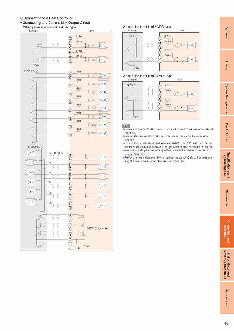
Featu
res
Lin
eu
pS
yste
m C
on
fi gu
ratio
nP
rod
uc
t Lin
eS
pe
cifi c
atio
ns
an
d
Ch
ara
cte
ristic
sD
ime
ns
ion
sC
on
nectio
n a
nd
Op
era
tion
Lis
t of M
oto
r an
d
Driv
er C
om
bin
atio
ns
Ac
cess
orie
s
49
Connecting to a Host Controller ◇Connecting to a Current Sink Output Circuit ●
When pulse input is of line driver type
NC
DriverController
10 mA max.
30 VDC max.
5 to 24 VDC
26C31 or Equivalent
2.7 kΩ
10 kΩ
10 kΩ
10 kΩ
3 kΩ
3 kΩ
3 kΩ
3 kΩ
3 kΩ
3 kΩ
3 kΩ
3 kΩ
10 kΩ
10 kΩ
10 kΩ
10 kΩ
10 kΩ
10 kΩ
10 kΩ
200 Ω
2.7 kΩ
200 Ω
0 V
0 V
0 V
0 V 0 V
R0
R0
R0
R0
R0
R0
33
31
32
35
36
22
23
24
25
26
27
28
29
30
11
12
13
14
15
16
17
18
1920
21
10
9
34
3
1
4
5
6
78
2
When pulse input is of 5 VDC typeDriverController
0 V
2.7 kΩ
10 kΩ
10 kΩ
200 Ω
2.7 kΩ
200 Ω
33
31
32
34
3536
5 VDC
When pulse input is of 24 VDC typeDriverController
2.7 kΩ
10 kΩ
10 kΩ
200 Ω
2.7 kΩ
200 Ω
33
31
32
34
35
36
24 VDC
0 V
Note
Use output signals at 30 VDC or less. If the current exceeds 10 mA, connect an external ●resistor R0.
Connect a terminal resistor of 100 ● Ω or more between the input of the line receiver
terminals.
Use a multi-core, twisted-pair shielded wire of AWG28 to 24 (0.08 to 0.2 mm● 2) for the
control input/output signal line (CN5), and keep wiring as short as possible (within 2 m).
Note that as the length of the pulse signal line increases, the maximum transmission ●frequency decreases.
Provide a minimum distance of 200 mm between the control I/O signal lines and power ●lines (AC lines, motor lines and other large-current circuits).

50
Featu
res
Lin
eu
pS
yste
m C
on
fi gu
ratio
nP
rod
uc
t Lin
eS
pe
cifi c
atio
ns
an
d
Ch
ara
cte
ristic
sD
ime
ns
ion
sC
on
nec
tion
an
d
Op
era
tion
Lis
t of M
oto
r an
d
Driv
er C
om
bin
atio
ns
Acce
sso
ries
Motor and Driver Combinations ■
Product names for motor and driver combinations are shown below.
TypeBuilt-In Controller Package Pulse Input Package
Product Name Motor Product Name Driver Product Name Product Name Motor Product Name Driver Product Name
Standard Type
AR46□CD-◇✽ ARM46□C
ARD-CD
AR46□C-◇✽ ARM46□C
ARD-C
AR66□CD-◇✽
AR69□CD-◇✽ARM66□CARM69□C
AR66□C-◇✽
AR69□C-◇✽ARM66□CARM69□C
AR98□CD-◇✽ ARM98□C AR98□C-◇✽ ARM98□CAR911□CD-◇✽ ARM911□C AR911□C-◇✽ ARM911□C
TH Geared Type
AR46□CD-T ■ ■-◇ ARM46□C-T ■ ■ AR46□C-T ■ ■-◇ ARM46□C-T ■ ■
AR66□CD-T ■ ■-◇ ARM66□C-T ■ ■ AR66□C-T ■ ■-◇ ARM66□C-T ■ ■
AR98□CD-T ■ ■-◇ ARM98□C-T ■ ■ AR98□C-T ■ ■-◇ ARM98□C-T ■ ■
PS Geared Type
AR46□CD-PS ■ ■-◇ ARM46□C-PS ■ ■ AR46□C-PS ■ ■-◇ ARM46□C-PS ■ ■
AR66□CD-PS ■ ■-◇ ARM66□C-PS ■ ■ AR66□C-PS ■ ■-◇ ARM66□C-PS ■ ■
AR98□CD-PS ■ ■-◇ ARM98□C-PS ■ ■ AR98□C-PS ■ ■-◇ ARM98□C-PS ■ ■
PN Geared Type
AR46□CD-N ■ ■-◇ ARM46□C-N ■ ■ AR46□C-N ■ ■-◇ ARM46□C-N ■ ■
AR66□CD-N ■ ■-◇ ARM66□C-N ■ ■ AR66□C-N ■ ■-◇ ARM66□C-N ■ ■
AR98□CD-N ■ ■-◇ ARM98□C-N ■ ■ AR98□C-N ■ ■-◇ ARM98□C-N ■ ■
Harmonic Geared Type
AR46□CD-H ■ ■-◇ ARM46□C-H ■ ■ AR46□C-H ■ ■-◇ ARM46□C-H ■ ■
AR66□CD-H ■ ■-◇ ARM66□C-H ■ ■ AR66□C-H ■ ■-◇ ARM66□C-H ■ ■
AR98□CD-H ■ ■-◇ ARM98□C-H ■ ■ AR98□C-H ■ ■-◇ ARM98□C-H ■ ■
A● (Single shaft) or M (Electromagnetic brake) indicating the type is entered where the box □ is located within the product name.
A number indicating the gear ratio is entered where the box ■■ is located within the product name, A number indicating the desired length of 1 (1 m), 2 (2 m) or 3 (3 m) for the cable indicated
with the product is entered where the box ◇ is located within the product name.
A✽ (Single shaft), B (Double shaft) or M (Electromagnetic brake) indicating the type is entered where the box □ is located within the product name of AR46□C(D)-◇, AR66□C(D)-◇,
AR69□C(D)-◇ and AR98□C(D)-◇.
A (Single shaft), B (Double shaft) indicating the type is entered where the box □ is located within the product name of AR911□C(D)-◇.
Product Line ■Product Name
OPX-2A
Specifications ■Display LED
Cable Length 5 m
Ambient Temperature 0∼+40°C (non-condensing)
Dimensions ■ (Unit = mm)
Control Module ●Mass: 0.25 kg
6.1
ϕ11.2
67.8
21.596
72
38
91.8
Cable ϕ4.7, 5000
Panel Cut-Out for Control Module ●(Thickness of the mounting plate: 1∼3 mm)
92 0 +0.8
68
0
+0.7
■Features
The internal driver parameter settings and data settings can be
established and changed. They can also be used for speed and I/O
monitoring, teaching, and so on.
The settings and monitoring details depend on the applicable products. ●
Control Module

Featu
res
Lin
eu
pS
yste
m C
on
fi gu
ratio
nP
rod
uc
t Lin
eS
pe
cifi c
atio
ns
an
d
Ch
ara
cte
ristic
sD
ime
ns
ion
sC
on
nec
tion
an
d
Op
era
tion
Lis
t of M
oto
r an
d
Driv
er C
om
bin
atio
ns
Acces
so
ries
51
Operation data and various parameters can be established and
edited on the computer, as well as I/O and operating speed
waveforms monitored.
The settings and monitoring details depend on the applicable products.●
Product Line ■Product Name
MEXE02
Connection between Computer and ■
Driver
PC
(Not supplied)
PC Interface Cable (Included)
5 m
USB Cable (Included)
0.5 m
Driver
Operating Environment ■
Operating
Systems
The OS supports 32-bit (x86) and 64-bit (x64) versions only.
Windows 2000 Professional Service Pack 4 or later✽1
Windows XP Home Edition Service Pack 3 or later
Windows XP Professional Service Pack 2
Windows XP Professional Service Pack 3✽2 or later
Windows Vista Home Basic Service Pack 2 or later
Windows Vista Home Premium Service Pack 2 or later
Windows Vista Business Service Pack 2 or later
Windows Vista Ultimate Service Pack 2 or later
Windows Vista Enterprise Service Pack 2 or later
Windows 7 Starter Service Pack 1 or later
Windows 7 Home Premium Service Pack 1 or later
Windows 7 Professional Service Pack 1 or later
Windows 7 Ultimate Service Pack 1 or later
Windows 7 Enterprise Service Pack 1 or later
CPU✽3 Intel Core Processor 2 GHz or more (The OS must be supported.)
Memory✽3 32-bit (x86) version: 1 GB or more
64-bit (x64) version: 2 GB or more
Hard Disk✽4 Available disk space of 30 MB or more
Disk Device CD-ROM drive
Serial Interface USB 1.1 1 port
1 Rollup 1 must be applied.✽
2 Service Pack 3 supports 32-bit (x86) version only✽
3 The OS operating conditions must be satisfied.✽
4 Microsoft .NET Framework 2.0 Service Pack 2 is required to use ✽ MEXE02. If it is
not already installed, it will be installed automatically, in which case up to 500 MB in
additional space is required.
Windows and Windows Vista are registered trademark of Microsoft Corporation in the ●United States and other countries. Pentium is a trademark of Intel Corporation.
Data Setting Software

52
Featu
res
Lin
eu
pS
yste
m C
on
fi gu
ratio
nP
rod
uc
t Lin
eS
pe
cifi c
atio
ns
an
d
Ch
ara
cte
ristic
sD
ime
ns
ion
sC
on
nec
tion
an
d
Op
era
tion
Lis
t of M
oto
r an
d
Driv
er C
om
bin
atio
ns
Ac
cess
orie
s
■Cables for AR Series AC Input Type
The AR Series comes with a 3 m cable for connection between the motor and driver.
When it is necessary to have a connection of a different length between motor and driver, a motor cable or extension cable must be used.
The cable for electromagnetic brake motor comes as a set of motor and electromagnetic brake cable.
Use a flexible motor cable if the cable will be flexed repeatedly.
Keep the overall cable length 30 m or less when using an extension cable to connect with a cable included with the AR Series.
System Configuration of Cables ●Driver
Motor
Connection Cable (Included)or
or
Controller
Connection Cable Set/Flexible Connection Cable Set1
Extension Cable Set/Flexible Extension Cable Set
General-Purpose Cable
Connector – Terminal Block Conversion Unit
2
3
4
Cable for RS-485
Communication Cable
Built-In Controller Package Driver
5
□1 Connection Cable Set
Flexible Connection Cable Set
For Standard Motors ●
Cable for Motor
For Electromagnetic Brake Motor ●
Cable for Motor Cable for Electromagnetic Brake
For details please contact the nearest Oriental Motor sales office.
For details please contact the nearest Oriental Motor sales office.
□2 Extension Cable Set
Flexible Extension Cable Set
For Standard Motors ●
Cable for Motor
For Electromagnetic Brake Motor ●
Cable for Motor Cable for Electromagnetic Brake

Featu
res
Lin
eu
pS
yste
m C
on
fi gu
ratio
nP
rod
uc
t Lin
eS
pe
cifi c
atio
ns
an
d
Ch
ara
cte
ristic
sD
ime
ns
ion
sC
on
nectio
n a
nd
Op
era
tion
Lis
t of M
oto
r an
d
Driv
er C
om
bin
atio
ns
Ac
cess
orie
s
53
□3 General-Purpose Cable
This is a shielded cable equipped
with a half-pitch connector at one
end of the cable that snaps onto
the driver.
The other end is laminated lead
wires aligned in order at a pitch
of 1.27 mm, which is convenient
for insulation displacement
connectors.
Note
Note that as the length of the pulse signal line between the driver and controller increases,●
the maximum transmission frequency decreases.
Install a connector that matches the controller you are using to the other end of the cable.●
Product Line ●Product Name Applicable Connector Length L (m)
CC36D1-1 Pulse Input Package
CN5 (36 pins)
1
CC36D2-1 2
Dimensions ● (Unit = mm)
Conductor: AWG28 (0.08 mm2)
L
43.4
6
ϕ7.5
Controller Side
Laminate
Shield
Driver Side
1.27
12.7
10±3
60±
15 10±3 10±3
30−10 0
□4 Connector – Terminal Block Conversion Unit
CC36T1
A terminal block conversion unit
connects a driver to a host
controller.
With a signal name plate for easy, ●one-glance identification of driver
signal names
DIN-rail mountable ● Application Crimp Terminal: Fork ●Terminal
Cable length: 1 m ●
Product Line ● Product Name Applicable Connector Length (m)
CC36T1 Pulse Input Package
CN5 (36 pins)1
Dimensions ● (Unit = mm)
3
26 27 28 29 30
1 2 4 5 6
31 32 33 34 35
7 8 9 10 11 12 13 14 15 16 17 18
19 3620 21 22 23 24 25
81
2×ϕ4.5 Mounting Hole
2×ϕ8 Counterbore ×3.5 Deep
6.35 1.27 7.62
120
162
14
26
36
3
61
54
40
DIN Rail
Terminal Block Pin Configuration
1000
43.4
6
43.4
6
39 8 83912.7 12.7
Recommended Crimp Terminals● 3.2 min.
6.2
max
.
5.8 min.
4.2 max.
· Terminal screw size: M3
· Tightening torque: 1.2 N·m
· Applicable minimum lead wire: AWG22 (0.3 mm2)
Note
Round terminals cannot be used.●
□5 Cable for RS-485 Communication
This cable is used to link drivers when
a built-in controller type is being
operated in a multi-drop manner.
Product Line ●Product Name Applicable Products
CC002-RS4 Built-In Controller Package
Dimensions ● (Unit = mm)
250
21.7
11.7
ϕ6.2
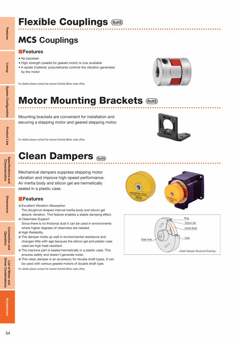
54
Featu
res
Lin
eu
pS
yste
m C
on
fi gu
ratio
nP
rod
uc
t Lin
eS
pe
cifi c
atio
ns
an
d
Ch
ara
cte
ristic
sD
ime
ns
ion
sC
on
nec
tion
an
d
Op
era
tion
Lis
t of M
oto
r an
d
Driv
er C
om
bin
atio
ns
Ac
cess
orie
s
Flexible Couplings
MCS Couplings
Features ■
No backlash ●High strength (usable for geared motor) is now available ● A spider (material: polyurethane) controls the vibration generated ●by the motor
For details please contact the nearest Oriental Motor sales office.
Motor Mounting Brackets
Mounting brackets are convenient for installation and
securing a stepping motor and geared stepping motor.
Clean Dampers Mechanical dampers suppress stepping motor
vibration and improve high-speed performance.
An inertia body and silicon gel are hermetically
sealed in a plastic case.
Features ■
Excellent Vibration Absorption●The doughnut-shaped internal inertia body and silicon gel
absorb vibration. This feature enables a stable damping effect.
Cleanness Support ●Since there is no frictional dust it can be used in environments
where higher degrees of cleanness are needed.
High Reliability ● The damper holds up well in environmental resistance and ●changes little with age because the silicon gel and plastic case
used are high heat-resistant.
The machine part is sealed hermetically in a plastic case. This ●ensures safety and doesn't generate noise.
This clean damper is an accessory for double shaft types. It can ●be used with various geared motors of double shaft type.
For details please contact the nearest Oriental Motor sales office.
VEXTA
VEXTA
VEXTA
VEXTA
Ring
Silicon Gel
Inertia Body
CaseShaft Hole
<Clean Damper Structural Drawing>
For details please contact the nearest Oriental Motor sales office.

55

For more information please contact:
Specifi cations are subject to change without notice.This catalogue was published in June, 2012.
This product is manufactured at a plant certified with the international standards ISO 9001 (for quality assurance) and ISO 14001 (for systems of environmental management).
ORIENTAL MOTOR (EUROPA) GmbH www.orientalmotor.de
European Headquarters and Düsseldorf Offi ceSchiessstraße 7440549 Düsseldorf, GermanyTel: 0211-5206700 Fax: 0211-52067099
Munich Offi ce
Carl-von-Linde-Straße 4285716 Unterschleißheim, GermanyTel: 089-318122500 Fax: 089-318122525
Hamburg Offi ce
Meckelfelder Weg 221079 Hamburg, GermanyTel: 040-76910443 Fax: 040-76910445
Jena Offi ce
Wildenbruchstraße 1507745 Jena, GermanyTel: 03641-675280 Fax: 03641-675288
Frankfurt Offi ce
Kruppstraße 10560388 Frankfurt, GermanyTel: 069-40149780 Fax: 069-40149782
Stuttgart Offi ce
Tel: 07335-924853 Fax: 07335-924854
ORIENTAL MOTOR (UK) LTD.www.oriental-motor.co.uk
Unit 5, Faraday Offi ce Park,Rankine Road, Basingstoke,Hampshire RG24 8AH U.K.Tel: 01256-347090 Fax: 01256-347099
ORIENTAL MOTOR (FRANCE) SARLwww.orientalmotor.fr
France Headquarters56, Rue-des Hautes Pâtures9200 Nanterre Cedex, FranceTel: 01 47 86 97 50 Fax: 01 47 82 45 16
Lyon Offi ce
10, Allée des Sorbiers69673 Bron Cedex, FranceTel: 04 78 41 15 02 Fax: 04 78 41 15 90
ORIENTAL MOTOR ITALIA s.r.l.www.orientalmotor.it
Italy HeadquartersVia A. De Gasperi, 8520017 Mazzo di Rho (Ml), ItalyTel: 02-93906346 Fax: 02-93906348
Bologna Offi ce
Via mori, 640054 Prunaro di Budrio (BO), ItalyTel: 051-6931249 Fax: 051-6929266
Verona Offi ce
Piazza Roma, 3A37066 Sommacampagna (VR), ItalyTel: 045-8961049 Fax: 045-8971978
ORIENTAL MOTOR CO., LTD.www.orientalmotor.co.jp
Headquarters4-8-1 HigashiuenoTaito-ku, Tokyo 110-8536, JapanTel: (03)6744-0361 Fax: (03)5826-2576
Printed in Europe UK/062012/VERS01
©Copyright Oriental Motor (Europa) GmbH 2012
This printed material uses ECF (Elementary Chlorine Free) paper and vegetable oil inks.This combination is environmentally friendly.
Controller Module (Sold separately)
CM10Features ■
Just Snap the CM10 On!
Your "pulse input" type driver can now function as
a "built-in controller package". You can have a great advantage
when installing and wiring the controller. Also, the CM10 is
available to control the motor via various serial ports such as USB,
RS-232C and , as well as via I/O.
For details, please contact the nearest Oriental Motor sales office.