STEPPED EJECTOR PINS · Dowel hole boring+Dowel pin driving V Available when head diameter H≧4...
1
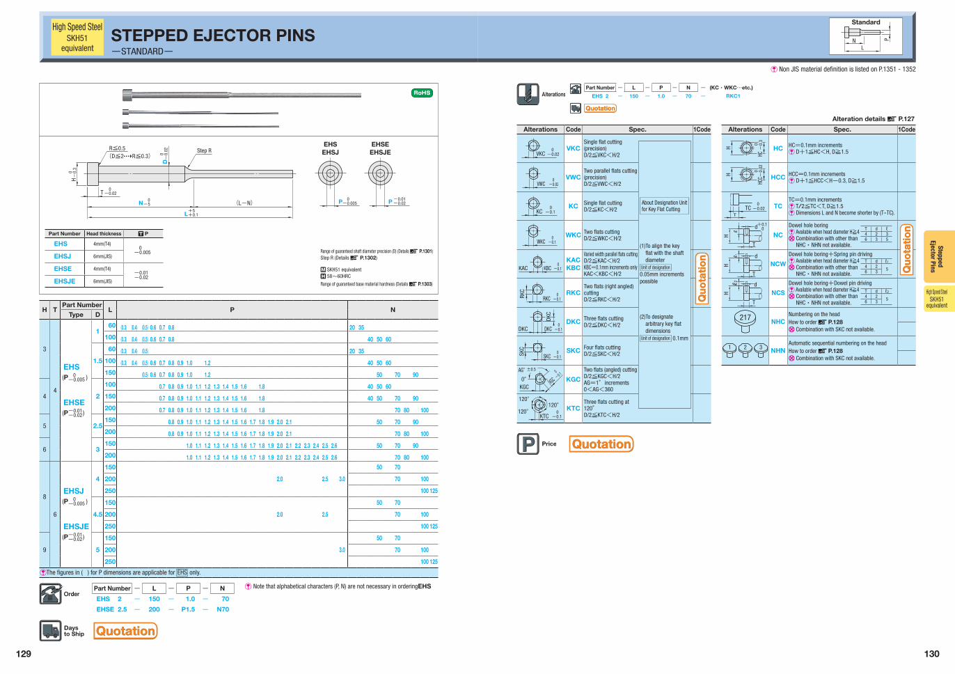
129 130 Stepped Ejector Pins Alteration details X P.127 Alterations Code Spec. 1Code Alterations Code Spec. 1Code VKC -0.02 0 VKC Single flat cutting (precision) D/2≦VKC<H/2 H -0.3 HC 0 HC HC=0.1mm increments V D+1≦HC<H, D≧1.5 VWC 0 -0.02 VWC Two parallel flats cutting (precision) D/2≦VWC<H/2 H HCC -0.02 0 HCC HCC=0.1mm increments V D+1≦HCC<H-0.3, D≧1.5 KC -0.1 0 KC Single flat cutting D/2≦KC<H/2 T 0 -0.02 TC TC TC=0.1mm increments V T/2≦TC<T, D≧1.5 V Dimensions L and N become shorter by (T-TC). WKC -0.1 0 WKC Two flats cutting D/2≦WKC<H/2 H T ℓ d +0.1 0 NC Dowel hole boring V Available when head diameter H≧4 U Combination with other than NHC・NHN not available. KAC -0.1 0 KBC KAC KBC Varied width parallel flats cutting D/2≦KAC<H/2 KBC=0.1mm increments only KAC<KBC<H/2 H ℓ1 T d NCW Dowel hole boring+Spring pin driving V Available when head diameter H≧4 U Combination with other than NHC・NHN not available. RKC RKC -0.1 0 RKC Two flats (right angled) cutting D/2≦RKC<H/2 ℓ 2 H T d NCS Dowel hole boring+Dowel pin driving V Available when head diameter H≧4 U Combination with other than NHC・NHN not available. DKC DKC DKC 0 -0.1 DKC Three flats cutting D/2≦DKC<H/2 217 NHC Numbering on the head How to order X P.128 U Combination with SKC not available. SKC -0.1 0 SKC SKC Four flats cutting D/2≦SKC<H/2 2 1 3 NHN Automatic sequential numbering on the head How to order X P.128 U Combination with SKC not available. ±0.5 0° KGC AG° 0 -0.1 KGC KGC Two flats (angled) cutting D/2≦KGC<H/2 AG=1°increments 0<AG<360 120° 120° -0.1 0 120° KTC KTC Three flats cutting at 120° D/2≦KTC<H/2 Part Number - L - P - N - (KC・WKC…etc.) EHS 2 - 150 - 1.0 - 70 - RKC1 About Designation Unit for Key Flat Cutting (1)To align the key flat with the shaft diameter Unit of designation 0.05mm increments possible (2)To designate arbitrary key flat dimensions Unit of designation 0.1mm T d ℓ 4 2 3 6 3 5 T d ℓ1 4 2 5 6 3 T d ℓ2 4 2 5 6 3 High Speed Steel SKH51 equivalent STEPPED EJECTOR PINS -STANDARD- N L P Standard Part Number - L - P - N EHS 2 - 150 - 1.0 - 70 EHSE 2.5 - 200 - P1.5 - N70 V Note that alphabetical characters (P, N) are not necessary in orderingEHS H T Part Number L P N Type D 3 4 EHS (P 0 -0.005 ) EHSE (P -0.01 -0.02 ) 1 60 (0.3) (0.4) (0.5) 0.6 0.7 0.8 20 35 100 (0.3) (0.4) (0.5) 0.6 0.7 0.8 40 50 60 1.5 60 (0.3) (0.4) (0.5) 20 35 100 (0.3) (0.4) (0.5) 0.6 0.7 0.8 0.9 1.0 1.2 40 50 60 150 (0.5) 0.6 0.7 0.8 0.9 1.0 1.2 50 70 90 4 2 100 0.7 0.8 0.9 1.0 1.1 1.2 1.3 1.4 1.5 1.6 1.8 40 50 60 150 0.7 0.8 0.9 1.0 1.1 1.2 1.3 1.4 1.5 1.6 1.8 40 50 70 90 200 0.7 0.8 0.9 1.0 1.1 1.2 1.3 1.4 1.5 1.6 1.8 70 80 100 5 2.5 150 0.8 0.9 1.0 1.1 1.2 1.3 1.4 1.5 1.6 1.7 1.8 1.9 2.0 2.1 50 70 90 200 0.8 0.9 1.0 1.1 1.2 1.3 1.4 1.5 1.6 1.7 1.8 1.9 2.0 2.1 70 80 100 6 3 150 1.0 1.1 1.2 1.3 1.4 1.5 1.6 1.7 1.8 1.9 2.0 2.1 2.2 2.3 2.4 2.5 2.6 50 70 90 200 1.0 1.1 1.2 1.3 1.4 1.5 1.6 1.7 1.8 1.9 2.0 2.1 2.2 2.3 2.4 2.5 2.6 70 80 100 8 6 EHSJ (P 0 -0.005 ) EHSJE (P -0.01 -0.02 ) 4 150 50 70 200 2.0 2.5 3.0 70 100 250 100 125 4.5 150 50 70 200 2.0 2.5 70 100 250 100 125 9 5 150 50 70 200 3.0 70 100 250 100 125 VThe figures in ( ) for P dimensions are applicable for EHS only. High Speed Steel SKH51 equivalent Part Number Head thickness T P EHS 4mm(T4) 0 -0.005 EHSJ 6mm(JIS) EHSE 4mm(T4) -0.01 -0.02 EHSJE 6mm(JIS) (D≦2 R≦0.3) 0 -0.005 N D P R≦0.5 H P -0.02 -0.01 -0.3 0 T 0 -0.02 0 -5 L +5 +0.1 -0.02 0 EHSJ EHSJE EHS EHSE (L-N) Step R Range of guaranteed shaft diameter precision (D) (Details X P.1301) Step R (Details X P.1302) R SKH51 equivalent Q 58~60HRC Range of guaranteed base material hardness (Details X P.1303) Quotation Quotation Quotation Quotation Quotation Quotation Quotation Quotation Quotation Quotation V Non JIS material definition is listed on P.1351 - 1352
Transcript of STEPPED EJECTOR PINS · Dowel hole boring+Dowel pin driving V Available when head diameter H≧4...
129 130
Stepped Ejector Pins
Alteration details X P.127
Alterations Code Spec. 1Code Alterations Code Spec. 1Code
VKC -0.02 0 VKC
Single flat cutting (precision)D/2≦VKC<H/2
H -0.
3HC
0
HC HC=0.1mm incrementsV D+1≦HC<H, D≧1.5
VWC0
-0.02VWC
Two parallel flats cutting (precision)D/2≦VWC<H/2
H
HCC -
0.02
0
HCC HCC=0.1mm incrementsV D+1≦HCC<H-0.3, D≧1.5
KC -0.1 0 KC Single flat cutting
D/2≦KC<H/2 T
0-0.02TC TC
TC=0.1mm incrementsV T/2≦TC<T, D≧1.5V Dimensions L and N become shorter by (T-TC).
WKC -0.1 0 WKC Two flats cutting
D/2≦WKC<H/2 H
T
ℓ
d+0.10
NC
Dowel hole boringV Available when head diameter H≧4U Combination with other than
NHC・NHN not available.
KAC -0.1 0
KBCKACKBC
Varied width parallel flats cuttingD/2≦KAC<H/2KBC=0.1mm increments onlyKAC<KBC<H/2
H
ℓ1
T
dNCW
Dowel hole boring+Spring pin drivingV Available when head diameter H≧4U Combination with other than
NHC・NHN not available.
RKC
RKC -0.1 0 RKC
Two flats (right angled) cuttingD/2≦RKC<H/2
ℓ2
H
T
d
NCS
Dowel hole boring+Dowel pin drivingV Available when head diameter H≧4U Combination with other than
NHC・NHN not available.
DKC
DKC
DKC 0-0.1
DKC Three flats cuttingD/2≦DKC<H/2
217 NHCNumbering on the headHow to order X P.128U Combination with SKC not available.
SKC
-0.1 0
SKCSKC Four flats cutting
D/2≦SKC<H/2 21 3 NHNAutomatic sequential numbering on the headHow to order X P.128U Combination with SKC not available.
±0.5
0°KGC
AG° 0-0.1
KGC KGC
Two flats (angled) cuttingD/2≦KGC<H/2AG=1°increments0<AG<360
120°
120°-0.1 0
120°
KTCKTC
Three flats cutting at120° D/2≦KTC<H/2
Part Number - L - P - N - (KC・WKC…etc.)
EHS 2 - 150 - 1.0 - 70 - RKC1
About Designation Unit for Key Flat Cutting
(1) To align the key flat with the shaft diameter
Unit of designation0.05mm increments possible
(2) To designate arbitrary key flat dimensions
Unit of designation 0.1mm
T d ℓ4 2 36 3 5
T d ℓ1
4 2 56 3
T d ℓ2
4 2 56 3
High Speed SteelSKH51
equivalentSTEPPED EJECTOR PINS-STANDARD-
NL
P
Standard
Part Number - L - P - N
EHS 2 - 150 - 1.0 - 70
EHSE 2.5 - 200 - P1.5 - N70
V Note that alphabetical characters (P, N) are not necessary in orderingEHS
H TPart Number
L P NType D
3
4
EHS(P 0-0.005 )
EHSE(P-0.01-0.02 )
1 60 (0.3) (0.4) (0.5) 0.6 0.7 0.8 20 35100 (0.3) (0.4) (0.5) 0.6 0.7 0.8 40 50 60
1.5
60 (0.3) (0.4) (0.5) 20 35100 (0.3) (0.4) (0.5) 0.6 0.7 0.8 0.9 1.0 1.2 40 50 60150 (0.5) 0.6 0.7 0.8 0.9 1.0 1.2 50 70 90
4 2
100 0.7 0.8 0.9 1.0 1.1 1.2 1.3 1.4 1.5 1.6 1.8 40 50 60150 0.7 0.8 0.9 1.0 1.1 1.2 1.3 1.4 1.5 1.6 1.8 40 50 70 90200 0.7 0.8 0.9 1.0 1.1 1.2 1.3 1.4 1.5 1.6 1.8 70 80 100
5 2.5150 0.8 0.9 1.0 1.1 1.2 1.3 1.4 1.5 1.6 1.7 1.8 1.9 2.0 2.1 50 70 90200 0.8 0.9 1.0 1.1 1.2 1.3 1.4 1.5 1.6 1.7 1.8 1.9 2.0 2.1 70 80 100
6 3150 1.0 1.1 1.2 1.3 1.4 1.5 1.6 1.7 1.8 1.9 2.0 2.1 2.2 2.3 2.4 2.5 2.6 50 70 90200 1.0 1.1 1.2 1.3 1.4 1.5 1.6 1.7 1.8 1.9 2.0 2.1 2.2 2.3 2.4 2.5 2.6 70 80 100
8
6
EHSJ(P 0-0.005 )
EHSJE(P-0.01-0.02 )
4
150 50 70
200 2.0 2.5 3.0 70 100
250 100 125
4.5
150 50 70
200 2.0 2.5 70 100
250 100 125
9 5
150 50 70
200 3.0 70 100
250 100 125
VThe figures in ( ) for P dimensions are applicable for EHS only.
High Speed SteelSKH51
equivalent
Part Number Head thickness T P
EHS 4mm(T4) 0-0.005
EHSJ 6mm(JIS)
EHSE 4mm(T4)-0.01-0.02
EHSJE 6mm(JIS)
(D≦2 R≦0.3)
0-0.005N
D
P
R≦0.5
H
P-0.02-0.01
-0.
3 0
T 0-0.02
0-5
L+5+0.1
-0.
02 0 EHSJ EHSJE
EHS EHSE
(L-N)
Step R
Range of guaranteed shaft diameter precision (D) (Details X P.1301)Step R (Details X P.1302)
R SKH51 equivalentQ 58~60HRC
Range of guaranteed base material hardness (Details X P.1303)
QuotationQuotation
QuotationQuotation
QuotationQuotation
Quo
tati
on
Quo
tati
on
Quo
tati
on
Quo
tati
on
V Non JIS material definition is listed on P.1351 - 1352