Stephen A. Byrne - nrc.gov
19
Stephen A. Byrne Vice President, Nuclear Operations 803.345.4622 March 16, 2001 RC-01 -0058 Document'Control Desk U.S Nuclear Regulatory Commission Washington, DC 20555 Gentlemen: VIRGIL C. SUMMER NUCLEAR STATION (VCSNS) DOCKET NO. 50/395 OPERATING LICENSE NO. NPF-12 REQUEST FOR ADDITIONAL INFORMATION TESTING OF KAOWOOL FIRE BARRIER SYSTEMS ON DECEMBER 28,1999 (TAC NO. MA9190) South Carolina Electric & Gas (SCE&G) is submitting the attached documents as a response to your request for additional information, dated February 20, 2001, on the testing of Kaowool fire barrier systems which was conducted on December 28, 1999. Should you have any questions, please call Mr. Jeff Pease at (803) 345-4124. Very truly yours Stephen A. Byrne JWP/SAB/dr Attachments C. J. J. Galan (w/o attachment) R. J. White L. A. Reyes K. R. Cotton NRC Resident Inspector H. C. Fields D. M. Deardorff Paulett Ledbetter D. L. Abstance EPIX Coordinator A. F. Robosky J. B. Knotts, Jr. INPO Records Center J&H Marsh & McLennan NSRC RTS (O-L-99-0437) RTS (O-C-99-1520) File (818.07) DMS (RC-01-0058) SCE&G I Virgil C. Summer Nuclear Station • P. 0. Box 88 •Jenkinsville, South Carolina 29065 .T (803) 345.5209 -www.scana.com A SCANA COMPANY Subject: ýPy
Transcript of Stephen A. Byrne - nrc.gov

Stephen A. Byrne Vice President, Nuclear Operations
803.345.4622
March 16, 2001 RC-01 -0058
Document'Control Desk U.S Nuclear Regulatory Commission Washington, DC 20555
Gentlemen:
VIRGIL C. SUMMER NUCLEAR STATION (VCSNS) DOCKET NO. 50/395 OPERATING LICENSE NO. NPF-12 REQUEST FOR ADDITIONAL INFORMATION TESTING OF KAOWOOL FIRE BARRIER SYSTEMS ON DECEMBER 28,1999 (TAC NO. MA9190)
South Carolina Electric & Gas (SCE&G) is submitting the attached documents as a response to your request for additional information, dated February 20, 2001, on the testing of Kaowool fire barrier systems which was conducted on December 28, 1999.
Should you have any questions, please call Mr. Jeff Pease at (803) 345-4124.
Very truly yours
Stephen A. Byrne
JWP/SAB/dr Attachments
C.
J. J. Galan (w/o attachment) R. J. White L. A. Reyes K. R. Cotton NRC Resident Inspector H. C. Fields D. M. Deardorff Paulett Ledbetter D. L. Abstance
EPIX Coordinator A. F. Robosky J. B. Knotts, Jr. INPO Records Center J&H Marsh & McLennan NSRC RTS (O-L-99-0437) RTS (O-C-99-1520) File (818.07) DMS (RC-01-0058)
SCE&G I Virgil C. Summer Nuclear Station • P. 0. Box 88 •Jenkinsville, South Carolina 29065 .T (803) 345.5209 -www.scana.com
A SCANA COMPANY
Subject:
ýPy

Document Control Desk Attachment I RC-01-0058 Page 1 of 2
COMMENTS TO KAOWOOL FIRE BARRIER TEST REPORT (REFERENCE TAC NO. MA9190)
NRC COMMENT 1: Circuit Me~qqerin~q
"Meggering was not performed throughout the testing, in accordance with GL86-10, Supplement 1."
RESPONSE:
There was a conscious decision by SCE&G based upon the following:
In accordance with GL 86-10, Supplement 1, the only monitoring required during fire exposure is for instrument cables. Cables included within Design Engineering scope of testing were power, control, and instrument. SCE&G conducted discussions with our test vendor and test laboratory regarding the performance of meggering during the test. It was agreed that, to protect the integrity of the computers used and data collected during the cable testing, we would do only the meggering necessary to bound the worst case cable / cable types.
NRC COMMENT 2: Raceway Wei~qhts
"The weight of the raceways and of cables and the information on cable types should be a part of the report."
RESPONSE:
The information on the weight of the raceway on a pound/linear foot basis will be added to the technical report as pages 332D, 332E and 332F, and have been included with this letter (Attachments V, VI, and VII, respectively). This information was derived from SCE&G Guidelines (EE-02, Attachment VIII), with selected pages included with this letter. These sheets (Attachments V, VI, and VII) are part of an existing calculation (DC07870-002).
NRC COMMENT 3: Cable Types
"The type of cable used in the fire test is included in the test report with no reference to the type of cable, conductor material, cable jacket material or dimensions."
RESPONSE:
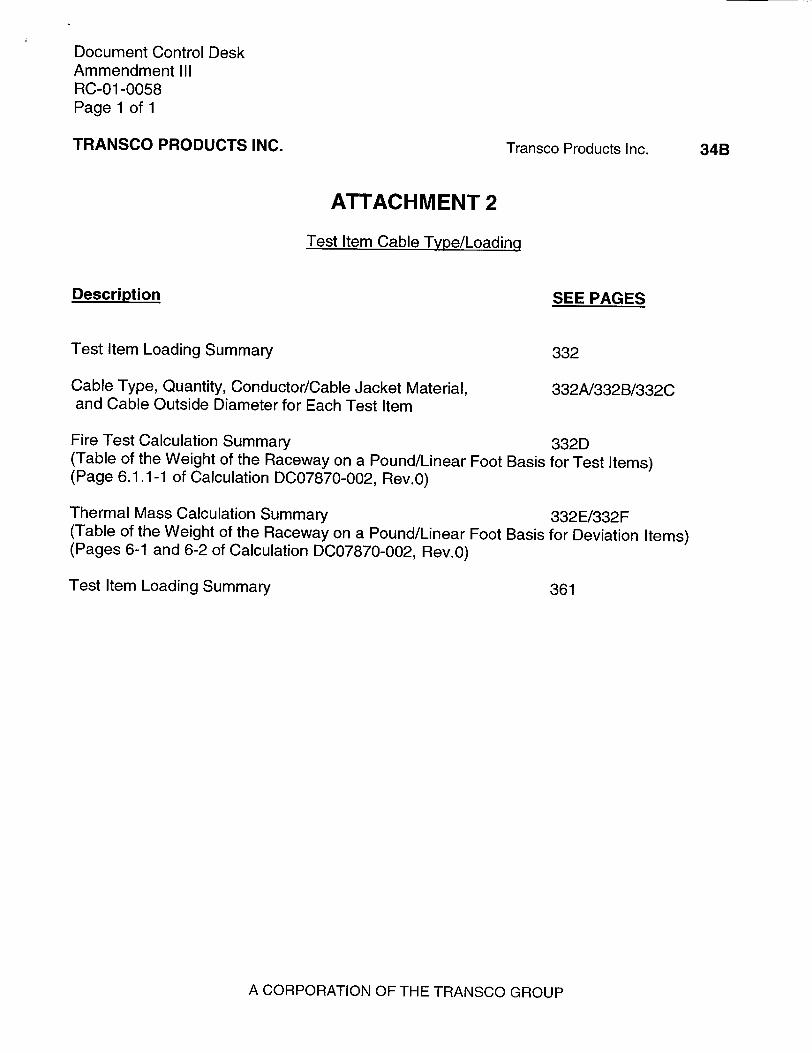
The type of cable, conductor material, cable jacket material, dimensions and weights will be added to the technical report as pages 332A, 332B and 332C, and have been included with this letter(Attachment IV).
Manufacturer's cut sheets for the various types of cables have been included with this letter (Attachment IX).

Document Control Desk Attachment I RC-01-0058 Page 2 of 2
NRC COMMENT 4: Meqgqer Scope
"The Insulation Resistance Measurement Data Sheets (Megger results) for Items 2, 5 and 6 (pages 214 to 220) are incomplete and should be provided."
RESPONSE:
The Insulation Resistance Measurement Data Sheets (Megger results) for items 2, 5, and 6 (pages 214 to 220) are incomplete because the Post Test megger was not completed for these cables. The justification for this follows:
Pages 209 through 213 show the meggering tests for cables 3A, 3B, 3C, 4A and 1 OA. Cable 3A was an EK-B1 B cable, 3B was an EK-B1J, 3C was an EK-A3H, 4A was an EK-B1 K, and 1OA was an EK-BIB. We will refer to these cables as Group I.
Pages 214 through 220 show the meggering tests for cables 2A, 5A, 5B, 5C, 5D, 5E and 6A. We will refer to these cables as Group II.
SCE&G gave careful consideration to the selection of cables for pre and post test meggerring. In order to reduce the time required for meggering, we agreed to test the five worst case temperature profile cables (Group I). Based upon the continuous temperature monitoring, SCE&G determined which of the pre hose test circuits were to be megger tested prior to hose stream testing. Worst case cables / cable types were selected at that time. This gave a representative cable from most of the different raceway configurations. We knew the Group II cables would be bounded by the Group I cables. For example, Group I cables 3A and 10A are the same as cable 5A of Group II; cable 3B is the same as 5D; cable 3C is the same as 5E; and cable 4A is smaller than 2A.
The five bounding cables / cable types (Group 1) were meggered at the completion of the hose stream test (post test meggerring).
NRC COMMENT 5: Test Plan Attachments
"Attachments 1 and 2, which were referenced in the test report, but were not included in the test report, should be provided."
RESPONSE:
During final assembly of the test report, the Design Engineering Test Contractor relocated the cable / trace details from the "Test Plan Attachments" into the body of the test report. This created the "omitted" attachments, as the information was included elsewhere.
For ease of reference, page 34A (Attachment 1) has been added (as Attachment II to this letter) to reference the new page location for each test item. Page 34B (Attachment 2) has been added (as Attachment III to this letter) to show the test item cable type/loading summary and where its pages are shown.

Document Control Desk Attachment II RC-01 -0058 Page 1 of 1
TRANSCO PRODUCTS INC.
ITEM #
1 2
3 4
5 6
7 8
9 10
11 12
Transco Products Inc.
ATTACHMENT 1
General Orientation and Confiauration of the Test Items and Test Slabs
PAGE (S)
304 311
323/339 340/345
347/348 365/373
374/384 385/391/392
393/397/398 399
404 404
A CORPORATION OF THE TRANSCO GROUP
34A
Document Control Desk Ammendment III RC-01 -0058 Page 1 of 1
TRANSCO PRODUCTS INC. Transco Products Inc.
ATTACHMENT 2
Test Item Cable Type/Loading
Description
Test Item Loading Summary
SEE PAGES
332
Cable Type, Quantity, Conductor/Cable Jacket Material, and Cable Outside Diameter for Each Test Item
332A/332B/332C
Fire Test Calculation Summary 332D (Table of the Weight of the Raceway on a Pound/Linear Foot Basis for Test Items) (Page 6.1.1-1 of Calculation DC07870-002, Rev.0)
Thermal Mass Calculation Summary 332E/332F (Table of the Weight of the Raceway on a Pound/Linear Foot Basis for Deviation Items) (Pages 6-1 and 6-2 of Calculation DC07870-002, Rev.0)
Test Item Loading Summary 361
A CORPORATION OF THE TRANSCO GROUP
34B

Document Control Desk Attachment IV RC-01 -0058 Paae A of C
TR07870-001, REV. 1 November 23, 2000
Page 332 A
Test Test Cable Quan- Cable Description: Cable Item Item: Type: tity: Outside No.: Dia.
1 4" EK-A1C 1 3/C, #350MCM-37 strands tinned copper, 2.84" Conduit extruded semi-conducting strand screen,
.175" Okoguard insulation, extruded semiconducting insulation screen .005" flat tinned copper tape helically applied, cabled with fire and moisture resistant fibrous fillers, .012" neoprene filled binder tape, double wrap .015" hypalon bedding tape, .005" corrugated bronze tape applied helically, .012" neoprene filled binder tape, .140" Okolon outer jacket
2 4" EK-Al E 1 3/C, #4/0 - 19 strands tinned copper, 2.42" Conduit extruded semi-conducting strand screen,
.175" Okoguard insulation, extruded semiconducting insulation screen .005" flat tinned copper tape helically applied, cabled with fire and moisture resistant fibrous fillers, .012" neoprene filled binder tape, double wrap .015" hypalon bedding tape, .005" corrugated bronze tape applied helically, .012" neoprene filled binder tape, .140" Okolon outer jacket
1-1/4" EK-B1L 1 7/C, 12 AWG (7 strands), 40 mils FR 0.80" max.
Conduit insulation (printed colors), cabled, zinc tape, 65 mils FR jacket Class B stranding, copper tin-coated conductor
3 6" x 6" EK-A3H 2 3/C, 8 AWG, stranded, 55 mils HT Kerite .79" max. Tray insulation, (printed colors), cabled, 65 mils
FR jacket (printed), Class B stranding, copper conductor
EK-A3J 2 3/C, 10 AWG, stranded 40 mils HT Kerite .64" max. insulation, (printed colors), cabled, 65 mils FR jacket (printed), Class B stranding: copper insulation
EK-B1J 12 4/C, 12 AWG (7 strands), 40 mils FR 0.69" max insulation (printed colors), cabled, zinc tape, 65 mils FR jacket Class B stranding,

Document Control Desk Attachment IV RC-01 -0058 Page B of C
TR07870-001, REV. 1 November 23, 2000
Pacie 332 BTest Test Cable Quan- Cable Description: Cable Item Item: Type: tity: Outside No.: Dia.
copper tin-coated conductor
EK-B1B 12 2/C, 9 AWG (7 strands), 40 mil FR 0.69" max insulation, (printed colors), cabled, zinc tape, 65 mils FR jacket, Class B stranding, copper tin-coated conductor
4 1il EK-BIK 1 5/C, 12 AWG (7 strands), 40 mils FR 0.74" max. Conduit insulation (printed colors), cabled, zinc
tape, 65 mils FR jacket. Class B stranding, I copper tin-coated conductor
6" x 36" Tray
EK-B1B
EK-C1A
EK-C6B
EK-A3J
EK-A3H
8
28
6
7
8
2/C, 9 AWG (7 strands), 40 mil FR insulation, (printed colors), cabled, zinc tape, 65 mils FR jacket, Class B stranding, copper tin-coated conductor
Dekoron Instrument Wire, Dekoron Part No. 1952-68640, 1/pair, shielded, 16 AWG 7-strand tinned copper conductors, primary insulation of 30 mils EPDM with a 15 mil Hypalon primary jacket, color coded black and white, conductors twisted with a 16 AWG 7-strand tinned copper drain wire, 2.0 mil aluminum/Mylar overall shield, 45 mil Hypalon outer jacket
7300" equipment cable, 12 Pair #18-19 strands tinned copper, .010" Tefzel insulation, color coded, twisted, cabled with fiberglass fillers, mylar/aluminum tape, 1 x #18 7-strand tinned copper drain wire, tape, .020" Tefzel jacket
3/C, 10 AWG, stranded 40 mils HT Kerite insulation, (printed colors), cabled, 65 mils FR jacket (printed), Class B stranding: copper insulation 3/C, 8 AWG, stranded, 55 mils HT Kerite insulation, (printed colors), cabled, 65 mils FR jacket (printed), Class B stranding, copper conductor
0.69" max
0.436"
0.528"
0.64" max
0.79" max
______________ a ________ L __________________________________________________ I ______________
5
Document Control Desk Attachment IV RC-01 -0058 Paae C of C
TR07870-001, REV. 1 November 23, 2000
Paqe 332 C
Test Test Cable Quan- Cable Description: Cable Item Item: Type: tity: Outside No.: Dia.
EK-B1J 8 4/C, 12 AWG (7 strands), 40 mils FR 0.69" max insulation (printed colors), cabled, zinc tape, 65 mils FR jacket Class B stranding, copper tin-coated conductor
EK-Al E 1 3/C, #4/0 - 19 strands tinned copper, 2.42" extruded semi-conducting strand screen, .175" Okoguard insulation, extruded semiconducting insulation screen .005" flat tinned copper tape helically applied, cabled with fire and moisture resistant fibrous fillers, .012" neoprene filled binder tape, double wrap .015" hypalon bedding tape, .005" corrugated bronze tape applied helically, .012" neoprene filled binder tape, .140" Okolon outer jacket
6 1-1/4" EK-A3J 1 3/C, 10 AWG, stranded 40 mils HT Kerite 0.64" max Conduit insulation, (printed colors), cabled, 65 mils
FR jacket (printed), Class B stranding: copper insulation
7 1" EK-B1 K 1 5/C, 12 AWG (7 strands), 40 mils FR 0.74" max. Conduit insulation (printed colors), cabled, zinc
tape, 65 mils FR jacket Class B stranding, copper tin-coated conductor
8 Junction NA 0 N/A N/A Box
9 Blank NA 0 N/A N/A Opening
10 Airdrop EK-B1B8 1 2/C, 9 AWG (7 strands), 40 mil FR 0.69" max insulation, (printed colors), cabled, zinc tape, 65 mils FR jacket, Class B stranding, copper tin-coated conductor (Same as EK-B1 B. 8 denotes reel number)
11 Junction NA 0 N/A N/A Box
12 Junction NA 0 N/A N/A Box

Document Control Desk Attachment V RC-01 -0058 Page 1 of 1
FIRE TEST CALCULATION SUMMARY
TR07870-001, Rev.1 Page 332D
CALC NO. DC07870-002, Rev.0 6.1.1-1
Conduit/Cable Tray Cable-Type SCE&G Test Length Size Weight Area Volume Outside We Total
Item Lnth Description (in) Diameter Cable Type Quantity Diameter Volume %Fill (b/ft) (sq ft.) (cu. ft.)(Ibt) (sq. ft.) (cu. ft.) (cu.ft.)
1 20 4" Open Air Conduit 4 4.026 9.820 0.088 1.768 EKaic 1 2.842 6.620 0.0441 0.881 0.881 49.963% I Bare # 8 Wire 1 0.146 0.051 0.0001 0.002 0.002 2a 20 Bundled 4" Conduit 4 4.026 9.820 0.088 1.768 EKale 1 2.424 4.573 0.0320 0.641 0.641 36.382% Bare # 8 Wire 1 0.146 0.051 0.0001 0.002 0.002 2b 20 Bundled 1.25" Conduit 1.25 1.380 2.010 0.010 0.208 EKb1l 1 0.800 0.378 0.0035 0.070 0.070 34.726%
Bare # 8 Wire 1 0.146 0.051 0.0001 0.002 0.002 3 20 6" x 6" Open Air Cable Tray 6 x 6 N/A 8.000 0.250 5.000 EKa3h 2 0.790 0.533 0.0034 0.068 0.136 29.433% EKa3i 2 0.640 0.240 0.0022 0.045 0.089 EKbli 11 0.690 0.268 0.0026 0.052 0.571 EKblb 12 0.690 0.284 0.0026 0.052 0.623
Bare # 8 Wire 1 0.146 0.051 0.0001 0.002 0.002 19 EKblj 1 0.690 0.268 0.0026 0.049 0.049 4 16 Open Air 1" Conduit 1 1.049 1.530 0.006 0.096 EKblk 1 0.740 0.311 0.0030 0.048 0.048 51.701%
Bare # 8 Wire 1 0.146 0.051 0.0001 0.002 0.002 5 20 6" x 36" Open Air Cable Tray 6 x 36 N/A 15.000 1.500 30.000 EKa3j 7 0.640 0.240 0.0022 0.045 0.313 10.356%
EKale 1 2.424 4.573 0.0320 0.641 0.641 EKbli 8 0.690 0.268 0.0026 0.052 0.415 EKblb 8 0.690 0.284 0.0026 0.052 0.415 EKa3h 8 0.790 0.533 0.0034 0.068 0.545 EKcla 28 0.440 0.081 0.0011 0.021 0.591 EKc6b 6 0.530 0.207 0.0015 0.031 0.184 Bare # 8 Wire 1 0.146 0.051 0.0001 0.002 0.002 6 16 1.25" Wall/Ceiling Conduit 1.25 1.380 2.010 0.010 0.166 EKa3E 1 0.640 0.240 0.0022 0.036 0.036 22.627%
Bare # 8 Wire 1 0.146 0.051 0.0001 0.002 0.002 7 16 1" Upgraded Open Air Conduit 1 1 .049 1.530 0.006 0.096 EKblk 1 0.740 0.311 0.0030 0.048 0.048 51.701% I Bare # 8 Wire 1 0.146 0.051 0.0001 0.002 0.002 10 16 Air Dropof SingleCable N/A N/A N/A N/A N/A Ekblb8 1 0.690 0.284 0.0026 0.042 0.042
Bare #8 Wire 0146002

Document Control Desk Attachment VI RC-01 -0058 Page 1 of 1
THERMAL MASS CALCULATION SUMMARY TR07870-001, Rev.1 Page 332E
CALC NO. DC07870-002, Rev.0 6-1
________ p Y
Item Description
Raceway Total Weight (lb/ft)
Fire Barrier Total Weight (lb/ft)
Fire Barrier Thermal Mass
(Ib)
1 4" Open Air Conduit 16.491 16.491 329.820
2a 4" Bundled Conduit 14.444 16.883 337.660
E 2b 1.25" Bundled Conduit 2.439
S3 6" x 6" Open Air Tray 16.221 16.221 324.420
l4 1" Open Air Conduit 1.892 1.892 30.272
5 6" x 36" Open Air Tray 33.494 33.494 669.880
U- 6 1.25" Wall/Ceiling Conduit 2.301 2.301 36.816
7 1" Upgraded Open Air Conduit 1.892 1.892 30.272
10 Air Drop of Single Cable 0.335 0.335 5.360 4.. ....... 2... ..
3-TW 2" Conduit - SWC87C
6-TW 4" Conduit - CSM1 I B 14.393 14.393 834.794
15-TW 3" Conduit - XX3413C 8.734 23.844 763.008
3" Conduit - XX3417C 8.734
2.5" Conduit - XX3574C 6.376
17-TW 3" Conduit - EDE27A 10.276 46.760 561.120
2.5" Conduit - EDE28A 7.365
2.5" Conduit - XX2980A 6.199
2.5" Conduit - XX2942A 6.657
2" Conduit - EDE23A 4.424
2" Conduit - EDE24A 4.424
2" Conduit - YY-1 953 4.424
1.5" Conduit - DGE23A 2.991
18-TW 3" Conduit - XX897A 8.238 16.110 80.550
3" Conduit - XX898A 7.872
25-TW 4" Conduit - ESM1 71 B 16.440 16.440 164.400
29-TW 3" Conduit - XX3414C 8.655 16.030 80.150
2.5" Conduit - XX3513C 7.375
38-TW 4" Conduit - CCM38C 14.393 28.786 1496.872
4" Conduit - CCM39C 14.393
50-TW 4" Conduit - ESM171B 16.440 16.440 542.520
5-TW 6" x 6" Cable Tray - 4065 20.154 41.248 989.952
6" x 6" Cable Tray - 4066 21.094
8-TW 6" x 6" Cable Tray - 4064 15.855 32.594 912.632
6" x 6" Cable Tray - 4065 16.739
21-TW 6" x 36" Cable Tray - 4284 52.856 173.786 6430.000
6" x 36" Cable Tray - 4314 92.741
6" x 36" Cable Tray - 5144 28.189
22-TW 6" x 24" Cable Tray - 4069 57.261 114.331 1715.000
6" x 24" Cable Tray - 4284 57.070
23-TW 6" x 36" Cable Tray - 4284 59.070 59.070 1418.000
0 C.)
D
I
4.068 4.068 158t.652,:,

Document Control Desk Attachment Vit RC-01-0058 Page 1 of 1
THERMAL MASS CALCULATION SUMMARY TR07870-001, Rev.1 Page 332F
CALC NO. DC07870-002, Rev.0 6-2
Description
1.25" Conduit - VLC4B
Raceway Total Fire Barrier Total Fire Barrier Weight Weight Thermal Mass (Ib/ft) (lb/ft) (Ib)
1 2.250 I 2.250
Equipment - XFN-468-VL 2752 lb
2764.375
10-TW 1.25" Conduit - VLC1A 2.250 2.250 2765.500
Equipment - XFN-46A-VL 2752 lb
13-TW 2" Conduit - XX251 1 C 4.287 4.287 12.861
16-TW 3" Conduit - XX1680D 8.034 8.034 96.408
19-TW 3" Conduit - XX894E 7.548 15.035 135.315
2" Conduit - XX895E 3.745
2" Conduit - XX893E 3.742
25-TW 1.25" Conduit - VLC1 7C 2.388 2.388 9.552 29-TW 2.5" Conduit - XX3574C 6.376 6.376 76.512
34-TW 3.5" Conduit - SWL11A 14.634 14.634 760.968
40-TW 2.5" Conduit - VUL52C 6.302 13.590 217.440
2.5" Conduit - VUL34B 7.288
47-TW 2 " Conduit - XX3702B 4.374 4.374 48.114
1.5" Conduit - VLC44B 3.125 3.125 1 R 7RA
11-TW 4"x 12" Cable Tray- 1012 17.146 17.146 1046.000
4" Conduit - CSM11B 14.393 28.786 1670.000 0 4" Conduit - CSM42B 14.393
0a F4-1 -W 1.25" Conduit - CCE21 A 2.511 5.383 16.149 a 0• 1.5" Conduit - XX31 16A 2.872
.0 42-TW 1" Conduit - CCM44B 1.841 4.713 28.278 cc
o 0 1.5" Conduit - XX3115B 2.872 •" 45-TW 4" x 6" Cable Tray - 1034 16.146 16.146 452.088
11 -TW CSM11B 4.573 9.146 27.438
CSM42B 4.573 to 41-TW CCE21A 0.501 0.883 1.325 0. O BIJ46XA 0.191
.• CCM16A 0.191 42-TW CCM44B 0.311 0.693 1.040
.0 BIJ56XB 0.191 O CCM26B 0.191
45-TW CCM38C 4.573 9.146 13.719
CCM39C 4.573
(0 11-TW add 3-EKal e cable (4.5731b/ft - each) 22.865 22.865 68.595 41-TW add 3-EKal e cable (4.5731b/ft - each) 14.602 14.602 21.903
(3 42-TW add 3-EKale cable (4.5731b/ft - each) 14.412 14.412 21.618
O 45-TW add 3-EKal e cable (4.5731b/ft - each) 22.865 22.865 34.297
Item
Ir r8-TW
C
0 V0
CL 6 CL
00i
Oo
51-TW
I

Document Control Desk Attachment VIII RC-01 -0058 Page 1 of 2
EE-02 ATTACHMENT VIII REVISION 1 PAGE 4 OF 8
STANDARD ELBOWS - RIGID STEEL AND ALUMINUM CONDUIT
AS PER SCE&G COMPANY V. C. SUMMER NUCLEAR STATION
Steel Aluminum Non. DIAMETERS Nipple RADII OFFSET Tangent Approx. Approx. Size Length Weight Weight
per 100 per 100
External Internal A B C D E F pieces pieces Inches Inches Inches Inches Inches Inches Inches Inches Inches Inches Inches Pounds Pounds
1/2 .840 .622 11 1/4 3.83 4.25 4.67 6.08 6.50 6.92 2.25 75 29
3/4 1.050 8.24 12 1/2 4.105 4.625 5.155 8.075 8.595 9.125 3.975 111 43
1 1.315 1.049 143/4 5.84 6.5 7.16 11.466 12.09 12.75 5.598 195 71
1 1/4 1.660 1.380 173/4 7.17 8.0 8.83 11.34 12.17 13.0 4.17 320 110
1 1/2 1.900 1.610 19 3/4 8.175 9.125 10.075 12.725 13.675 4.625 4.55 423 153
2 2.375 2.067 221/2 9.0625 10.25 11.4375 14.5 15.6875 16.875 5.4375 671 249
21/2 2.875 2.469 26 11.747 13.137 14.627 20.87 22.31 23.75 9.125 1194 437
3 3.500 3.068 30 10.125 15.875 17.625 24.375 26.125 27.875 10.25 1807 767
31/2 4.000 3.548 39 1/2 13.00 15.00 17.00 21.75 23.75 25.75 8.75 2853 1036
4 4.500 4.026 39 1/2 18.875 21.125 23.375 28.5 30.75 33 9.625 3373 1228
5 5.563 5.047 59 1/2 21.22 24.00 26.78 32.12 34.9 37.68 10.90 7388 2490
6 6.625 6.065 76 26.68 30.00 33.31 40.13 43.44 46.75 14.14 12287 3850

Document Control Desk Attachment Vill RC-01 -0058 Page 2 of 2
EE-02 ATTACHMENT Vill REVISION 1 PAGE 8 OF 8
RIGID STEEL AND ALUMINUM CONDUIT WEIGHT AND DIMENSIONS
CONDUIT COUPLINGS Under- Nominal writers Weights f
Nominal Wall Outside Inside Internal Length Min. Pounds per Outside Diameter, Length Approximate Weight Pieces Size Thickness Diameter Diameter Traverse Without Weight t 100 ft incl. Inches Inches per 100 pcs. Pounds Per
Inches Inches Inches Inches Area Sq. Couplings Lbs./100 coupling Standard
Inches ft incl. Carton
coupling STEEL ALUMINUM STEEL ALUMINUM STEEL ALUMINUM
1/2 .109 .840 .622 .304 9'11-1/4" 79.0 29.8 1.010 1.078 1-9/16 12 6.1 100
3/4 .113 1.050 .824 .533 9'11-1/4" 105.0 39.8 1.250 1.328 1-5/8 21 9.1 50
1 .133 1.315 1.049 .864 9'11" 153.0 58.9 1.525 1.562 2 34 12.5 50
1-1/4 .140 1.660 1.380 1.495 9'11" 201.0 79.8 1.869 1.953 2-1/16 54 18.9 50
1-1/2 .145 1.900 1.610 2.036 9'11" 249.0 95.6 2.155 2.219 2-1/16 74 23.3 50
2 .154 2.375 2.067 3.355 9'11" 334.0 128.8 2.730 2.750 2-1/8 121 34.6 25
2-1/2 .203 2.875 2.469 4.788 9'10-1/2" 527.0 204.7 3.250 3.281 3-1/8 172 68.3 t
3 .216 3.500 3.068 7.393 9'10-1/2" 690.0 268.0 4.000 3.937 3-1/4 250 91.4 t
3-1/2 .226 4.000 3.548 9.886 9'10-1/4" 831.0 321.3 4.625 4.437 3-1/8 425 108.0 t
4 .237 4.500 4.026 12.730 9'10-1/4" 982.0 382.1 5.000 5.000 3-1/2 474 142.0 t
5 .258 5.563 5.047 20.006 9'10 1344.0 521.5 6.296 6.219 3-3/4 700 241.9 t
6 .280 6.625 6.065 28.891 9'10 1770.0 677.5 7.390 7.312 4 750 321.0 t
* Tolerance of ±_¼ inch applies to the required length (including coupling). t Weights indicated apply whether the conduit is enameled or zinc coated or both. f Alloy and Temper: Rigid conduit, couplings and elbows, 6063T42. t Packed in bulk.

Document Control Desk Attachment IX RC-01-0058 Page 1 of 6
List of Cable Manufacturers
Dekoron/Samuel Moore Kerite Okonite
Glossary of Terms and Definitions
EPDM: Ethylene Propylene Diene Monomer is an elastomeric membrane.
FR Insulation: An extruded vulcanized flame retardant synthetic rubber insulation.
FR Jacket: An extruded thermosetting (vulcanized) flame retardant synthetic rubber jacket.
HT Kerite: High temperature Kerite - an extruded vulcanized discharge resistant synthetic rubber insulation for cables rated 600-25000 Volts.
Okoguard Insulation: Okonite's registered trade name for its exclusive ethylene propylene insulation.
Okolon: Okonite's registered trade name for its vulcanized hypalon compound which is mechanically rugged and resists abrasion, tearing, or cutting.
Okoprene: Okonite's registered trade name for its neoprene based jacketing or low voltage insulation material.
Tefzel: DuPont's registered trade name for a modified version of ETFE (ethylenetetrafluoroethylene) fluoropolymer.

Document Control Desk Attachment IX RC-01-0058 Page 2 of 6
GLOSSARY OF KERITE TERMS
INSULATION COMPONENTS AND SYSTEMS (5000-138000 Volts)
Permashield-An extruded layer of high dielectric constant (high SIC) insulating material, superior to semiconductirig extrusions, to reduce the stress and limit available energy at insulation surfaces
SPS-Single Permashield-An extruded layer of Permashield between the conductor and the inr-er wall of
insulation
DPS-Double Permashield-An extruded layer of Permashield under and over the wall of insulation.
TPS-Triple Permashield-Three extruded layers of Permashield, one over the conductor, one over the first layer of insulation, and one over the second layer of insulation
KERITE INSULATIONS
HTK-High Temperature Kerite - An extruded vulcanized synthetic rubber insulation for cables rated 600-25000 volts
HVK-High Voltage Kerite - An extruded vulcanized synthetic rubber insulation for cables rated 35000 - 138000 volts.
FR Insulation-An extruded vulcanized flame retardant synthetic rubber insulation.
KERTE JACKETS AND FINISHES
HTNS - High Temperature Electrical jacket-An extruded vulcanized discharge resistant synthetic rubber
jacket, used on 5000 - 8000 volt non-shielded cables
FR Jacket - An extruded thernosetting (vulcanized) flame retardant synthetic rubber jacket
POB - A composite finish covered with a saturated woven braid which is highly flame retardant.
TF Jacket - An abrasion resistant and highly flexible polyurethane jacket
SPLICE AND TERMINAL ABBREVIATIONS
IT-Indoor terminal (print)
OT-Outdoor terminal (print)
S-Splice (print)
The Kerite Company 49 Day Street
Seymour, CT 06483 the kerite company

Document Control Desk Attachment IX RC-01-0058 Page3of6 Product Data
Section 10: Sheet 1
Engineering Data Handling and Storage Recommendations
On receipt, cable protective covering should be inspected for evidence of damage during shipment. Report should
immediately be made to carrier it evidence of damage is found. Unloading should be accomplished so that
equipment used does not contact cable surface, and in the case of protective wrap that the equipment does not
contact the protective wrap. If unloading is accomplished by crane, either a cradle supporting the reel flanges or a
shaft through the arbor hole should be used. If a fork lift is utilized, the forks must lift the reel at 900 to the flanges
and must be long enough to make complete lifting contact with both flanges. Under no circumstances should the
forks contact the cable surface or protective wrap. If an inclined ramp is used for unloading, the ramp must be wide
enough to contact both flanges completely and stopping of the reels at the bottom shall be accomplished by using the reel flanges and not the surface of the cable.
Under no circumstances should reels be dropped from the delivering vehicle to the ground.
Reels should be stored on a hard surface so that flanges do not sink into the earth and allow the weight of the reel
and cable to rest on the cable surface.
Reels should be stored in an area where construction equipment, falling or flying objects or other materials will not
contact the cable.
Cable should be stored in an area where chemicals or petroleum products will not be spilled or sprayed on the cable.
When a reel of cable is rolled from one point to another, care must be taken to see that there are no objects on the
surface area which could contact or damage the cable surface or protective wrap. cable should be stored in an area
away from open fires or sources of high heat. If a length of cable has been cut from the reel, the cable end should be immediately resealed to prevent the entrance of moisture.
When cable has been stored out of doors in cold weather, care must be taken to see that it is not installed at temperatures lower than the following: ..................................................................-----------------------------------------------------------------------.. .
Minimum Temperature
Okonite Trade Name Type of Insulation for Installation Okoseal PVC -10°C Okonite EPR -40°C
Okoguard EPR -40°C Okolene Polyethylene -40°C
X-Olene XLPE -40°C Okoprene Neoprene -20°C Okolon Hypalon -200C
Temperatures for any other compounds can be furnished on request.
January 1, 1972
THE OKONITE COMPANY Ramsey, New Jersey 07446

Document Control Desk Attachment IX RC-01-0058 Page 4 of 6 Product Data
Section 1: Sheet 2a
Glossary of Terms and Definitions AAR American Association of Railroads. AEIC Association of Edison Illuminating Companies. ALS Factory assembled cables, one or more insulated conductors, enclosed in an aluminum sheath. ANSI American National Standards Institute.
ASTM American Society For Testing And Materials. AWM Appliance wiring material. BM Federal Bureau of Mines. C-L-X® Okonite's trade name for its continuous, corrugated, impervious metallic-sheathed cables.
CMPF® A corrugated metal tape finish with a wall of Okoseal or Okolene bonded to it. Provides high compressive strength. CSA Canadian Standards Association. CTC Designation for Centralized Traffic Control Code Line cable. DEL Diesel electric locomotive and car wiring.
DLO Diesel Electric locomotive and car wiring. EEl Edison Electric Institute. FILLER TAPE Used for filling irregular surfaces around mechanical type jugs and connectors to obtain a smooth surface for taping of splices and terminations. FMPF A flat metal tape armor with plastic finish bonded to it. Provides high compressive strength and outstanding gopher and rodent protection.
FULLY BONDED Oil well cable where all elements of construction are bonded together to prevent gas or oil migration. G Multi-conductor, flat or round cable with ground conductor. GC Indicates cable with insulated ground check in place of one of the ground conductors. IEEE Institute of Electrical and Electronics Engineers.
IPCEA Insulated Power Cable Engineers Association. KTA Thermoplastic insulated, aluminum shielded, polyethylene jacketed communication cable. KTA-8 Same construction as KTA, except for a galvanized steel messenger built into the cable jacket. KTC Same construction as KTA except for a copper shield.
KTC-F Same construction as KTC, with polyethylene/petroleum jelly filling the interstices and applied under and over the shield for outstanding moisture resistance. KTI Thermoplastic insulated copper shielded. double polyethylene jacketed, direct burial communication cable. KTr-MR Same construction as KU except for a moisture resistant ethylene copolymer coating on both sides of the shield.
LOXARMOR®. An interlocked "S" shaped armor cable covering, normally galvanized steel or aluminum.
MANSON TAPE Premium grade friction tape. MIL U.S. Government - Military Specification MTW Machine tool wiring. NAED National Association of Electrical Distributors.
NEC National Electric Code. NECA National Electrical Contractors Association. NEMA National Electrical Manufacturers Association.
The Okonite Company. 1972
C-L-X® products manufactured in the United States under license granted by Kabelmetal of Hannover. Germany

Document Control Desk Attachment IX RC-01-0058 Page 5 of 6 Product Data
Section 1: Sheet 2b
Glossary of Terms and Definitions OKOCLAD® Okonite's trade name for its smooth sheath Type ALS cable. OKOCORD® Rubber insulated, reinforced jacketed, mold-cured portable, flexible cables.
OKOCOR-EP Ethylene propylene insulation for mining cables.
OKOFLEX® Bundled pneumatic instrumentation tubing, either copper, aluminum or plastic.
OKOGUARD® Okonite's registered trade name for its exclusive ethylene-propylene base, thermosetting compound, whose
optimum balance of electrical and physical properties is unequalled in other solid dielectrics.
OKOGUAR D LL Specially compounded ethylene propylene insulation with low loss characteristics.
OKOGUARD TAPE An ethylene propylene based insulating tape, recommended for high voltage, high temperature splicing
applications in cables insulated with ethylene propylene, butyl, oil-based and polyethylene (thermoplastic and cross-linked)
compounds.
OKOLENE® Low loss thermoplastic polyethylene-base insulation or sheath. OKOLON® Vulcanized Hypalon compound which is mechanically rugged and resists abrasion, tearing or cutting.
OKONEX-CLF TAPE® Heat, moisture and ozone-resistant butyl based insulating tape.
OKONITE Heat resistant, mechanically rugged ethylene-propylene based insulating compound.
OKONITE NO.35 TAPE Neoprene based jacketing tape. OKONITE #70 A neoprene impregnated nylon mesh tape designed for reinforcing cable jackets in vulcanized or non-vulcanized cable splices.
OKONITE-OKOPRENE Combination insulation/jacket. OKONITE-OKOSHEATH Combination insulation/jacket.
OKOPRENE® Neoprene based jacketing or low voltage insulation material. Excellent resistance to flame, impact and abrasion.
OKOSEAL® A polyvinyl chloride compound with excellent resistance to flame, oil and most chemicals. Designed especially as jacketing and low voltage insulation material.
OKOSEAL-N Polyvinyl chloride insulated nylon jacketed low voltage cable.
OKOSHEATH® Moisture-resistant rubber compound serving as insulation or sheath. OKOTHERM® Silicone heat-resistant rubber insulation or sheath.
P Pennsylvania Department of Mines.
P-30 600V control cables.
P-45 IOOOV control cables. PN-20 Small diameter 600V control cables.
POLYPROPYLENE Down hole cable insulation with excellent heat, oil and moisture resistance.
P-OS Single or multiple pair instrumentation cable with overall shield.
REA Rural Electrification Administration.
RED SADDLE Pre-formed Okoprene filler which provides a uniform cushion or barrier between the conductors of flat type
portable cables. RHH Heat resistant rubber for dry locations. RHW Moisture and heat resistant rubber.
SEMI-CON A semi-conducting treated tape or compound.
SHD Portable cable having three insulated and shielded conductors with three ground conductors.
SILICONE RUBBER A flexible, mechanically rugged insulating compound with excellent electrical properties and out
standing resistance to weather, oils and most chemicals.

Document Control Desk Attachment IX RC-01-0058 Page 6 of 6 Product Data
Section 1: Sheet 2c
Glossary of Terms and Definitions SJO 300 volt junior hard service flexible cord. so 600 volt extra heavy duty flexible cord. SP-OS Multiple shielded pair instrumentation cable with overall shield. SRG Silicone-Rubber impregnated glass tape..
STEELPIC Thermoplastic insulated, aluminum and steel shielded polyethylene jacketed communication cable. THHN Flame retardant, heat resistant thermoplastic with nylon jacket for dry locations. THW Flame retardant, moisture and heat resistant thermoplastic. THWN Flame retardant, moisture and heat resistant thermoplastic with nylon jacket.
TIREX® Okonite's trade name for its cured-in-lead, neoprene jacketed portable cords. TW Flame retardant, moisture resistant thermoplastic. UL Underwriters Laboratories. UR-P Okolene insulated underground residential distribution cable.
UR-X X-Olene insulated underground residential distribution cable. USE Underground service entrance cable. VFR/LS Okonite's designation for its very flame resistant, low smoke emitting jacketing compound. VULCANIZER COMPOUND An ethylene propylene based semi-conducting compound for use as strand screen in vulcanized splices in high voltage, solid dielectric cables.
VULCANIZER TAPES A complete line of tapes for use with all cable vulcanizers. W Multi-conductor flat or round cable without ground conductors. WATERTITE® An organic based, synthetic rubber, moisture and heat resistant insulation. WTC 300V Supervisory Control Cable.
XHHW Flame retardant, moisture and heat resistant cross linked thermosetting polyethylene. X-OLENE® Chemically cross-linked (vulcanized) polyethylene. X-OLENE (FM R) Specially compounded, chemically cross-linked polyethylene insulation with outstanding flame and moisture resistance.
May, 1974
THE OKONITE COMPANY Ramsey, New Jersey 07446