
Steels for Surface Hardening - javadmola.files.wordpress.com file15 3 Case/Surface Hardening Methods...
42
Steel Application / Ferrous Materials II SS2015 1 Lecture 7 Steels for Surface Hardening Dr. Javad Mola Institute of Iron and Steel Technology (IEST) Tel: 03731 39 2407 E-mail: [email protected]
Transcript of Steels for Surface Hardening - javadmola.files.wordpress.com file15 3 Case/Surface Hardening Methods...

Ste
el A
pp
licati
on
/ F
err
ou
s M
ate
rials
II S
S2015
1
Lecture 7
Steels for Surface
Hardening
Dr. Javad Mola
Institute of Iron and Steel Technology (IEST)
Tel: 03731 39 2407
E-mail: [email protected]

Ste
el A
pp
licati
on
/ F
err
ou
s M
ate
rials
II S
S2015
2
Applications of Case Hardened Steels
Applications where wear and severe stresses act only on the surface of a part

Ste
el A
pp
licati
on
/ F
err
ou
s M
ate
rials
II S
S2015
3
Case/Surface Hardening Methods
Layer additions Hardfacing
Fusion hardfacing (welded overlay)
Thermal spray (bonded overlay) Coatings:
Electrochemical plating Chemical vapor deposition
(electroless plating) Thin films (physical vapor
deposition, sputtering, ion plating)
Ion mixing
Substrate treatment Selective hardening methods:
Flame hardening Induction hardening Laser hardening Electron beam hardening Ion implantation Selective carburizing and nitriding Use of arc lamps
Diffusion methods (composition modification at surface):
Carburizing Nitriding Carbonitriding Nitrocarburizing Boriding Titanium-carbon diffusion Toyota diffusion process

Ste
el A
pp
licati
on
/ F
err
ou
s M
ate
rials
II S
S2015
4
Induction/Flame Hardening
No change in the chemical composition of the surface layer Carbon content must be high enough to achieve a high surface hardness after quenching (typically above 0.35 mass-%C).
Surface hardness is a function of the solute C. Very fast heating and short exposure time necessitates the use of a higher holding
temperature than in through-hardening by normal Q&T High cooling rates possible without cooling medium, only through heat dissipation to
inner sections hardening depth larger than in through-hardening The microstructure at inner sections (tempered martensite in steels with high
hardenability and normalized in unalloyed steels) is not affected by induction/flame hardening
The wear and fatigue resistance of the case-hardened part improves with the increased surface hardness and development of compressive residual stresses
Low temperature tempering/stress relieving usually in the range of 140-200 °C to maintain a high surface hardness
Hardening depth depends on: depth of austenitization cooling rate hardenability of steel
Ste
el A
pp
licati
on
/ F
err
ou
s M
ate
rials
II S
S2015
5
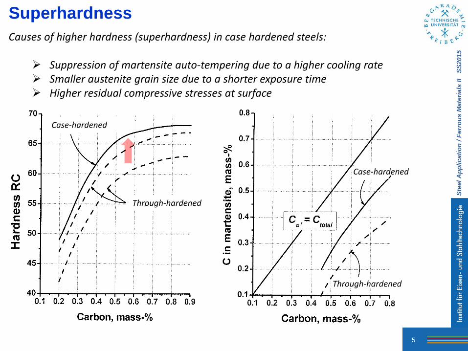
Superhardness
Causes of higher hardness (superhardness) in case hardened steels:
Suppression of martensite auto-tempering due to a higher cooling rate Smaller austenite grain size due to a shorter exposure time Higher residual compressive stresses at surface
Case-hardened
Through-hardened
Through-hardened
Case-hardened

Ste
el A
pp
licati
on
/ F
err
ou
s M
ate
rials
II S
S2015
6
Induction Hardening Schematic of the magnetic fields and induced currents
produced by several types of induction coils
Heating is accomplished by placing a steel part in the magnetic field generated by high-frequency alternating current passing through an inductor, usually a water-cooled copper coil. The depth of heating produced by induction is related to the frequency of the alternating current: The higher the frequency, the thinner or more shallow the heating. Therefore, deeper case depths and even through hardening may be produced by lower frequencies.
Outer diameter heating, single-turn coil Outer diameter heating, multi-turn coil
Inner diameter heating, multi-turn coil Surface heating, single-turn coil

Ste
el A
pp
licati
on
/ F
err
ou
s M
ate
rials
II S
S2015
7
Heating Rate and Starting Microstructure
Change in the Ac3 temperature of 1042 steel as a function of microstructure and heating rate
(1093 °C)
(760 °C)
1042 steel Annealed
Normalized
Q&T
(2778 °C/s) (28 °C/s)

Ste
el A
pp
licati
on
/ F
err
ou
s M
ate
rials
II S
S2015
8
Induction Hardening: Starting Microstructure
Influence of the microstructure prior to induction hardening on the
hardness profile of SAE 1070 steel with 0.70%C, 0.20%Si, and
0.80%Mn.
Hardness profiles for 1550 and 5150 steels after induction hardening of
two starting microstructures, furnace cooled and water quenched
prior to induction hardening.
Hardening time: 1 sec
Distance from surface, mm Distance from surface, mm
Vic
kers
Ha
rdn
ess
Ha
rdn
ess
(ap
pro
xim
ate
), H
RC
Ha
rdn
ess,
HR
C
Q&T
normalized
annealed

Ste
el A
pp
licati
on
/ F
err
ou
s M
ate
rials
II S
S2015
9
Flame Hardening
Flame hardening consists of austenitizing the surface of a steel by heating with an oxyacetylene or oxyhydrogen torch and immediately quenching with water. This results in a hard surface layer of martensite over a softer interior core with a ferrite-pearlite structure. There is no change in composition. Therefore, the flame-hardened steel must have adequate carbon content for the desired surface hardness.
Effect of flame speed on depth of hardening of a 1050 steel forging. The slower the rate of travel, the greater the heat penetration and the depth of hardening.

Ste
el A
pp
licati
on
/ F
err
ou
s M
ate
rials
II S
S2015
10
Flame Hardening Spot (stationary) flame hardening
of a rocker arm
Spot (stationary) flame hardening of the internal lobes of a cam
Progressive flame hardening
Stationary flame head
Rotating workpiece
Rotating workpiece
Stationary flame head
Rotating flame head

Ste
el A
pp
licati
on
/ F
err
ou
s M
ate
rials
II S
S2015
11
Strength vs Hardening Depth
Torsional strength (major requirement for transmission of torque in shafts and axles) as a function of case depth for various grades of steel
Case Hardening Depth
Radius
Case Hardening Depth
Radius
Tors
ion
al S
tren
gth
, M
Pa
Tors
ion
al S
tren
gth
, M
Pa
Through-hardened Through-hardened

Ste
el A
pp
licati
on
/ F
err
ou
s M
ate
rials
II S
S2015
12
Carburizing
Carbon content of the surface is increased by exposure to an appropriate atmosphere at a temperature in the austenite phase field. Hardening is accomplished when the high-carbon surface layer is quenched to form martensite.
Steels for carburizing usually have base carbon contents around 0.2%. The maximum carbon content in a carburized steel is generally between 0.8 and 1%. Complications at higher C concentrations:
Carbide formation Brittle martensite Retained austenite
Typical carburizing temperatures: 850-950 °C, but sometimes higher temperatures are used to reduce cycle times and/or produce deeper depths of the high-carbon surface layer.
Two important processes influence the introduction of carbon into austenite: The environmental reaction that causes carbon to be absorbed at the surface of
the steel (adsorption). The rate at which carbon can diffuse from the surface to the interior of the steel
(diffusion). Carbon is introduced by the use of gaseous atmospheres (gas carburizing), salt baths
(liquid carburizing), solid compounds (pack carburizing), and by plasma carburizing.

Ste
el A
pp
licati
on
/ F
err
ou
s M
ate
rials
II S
S2015
13
Gas Carburizing
Schematic of a gas carburizing process involving partial combustion of a hydrocarbon, which acts as the source of carbon. The CO molecules are
adsorbed and dissociate on the steel surface. The adsorbed C atoms subsequently diffuse into the bulk.

Ste
el A
pp
licati
on
/ F
err
ou
s M
ate
rials
II S
S2015
14
Gas Carburizing Equilibrium percentages of carbon monoxide and carbon dioxide required to maintain various carbon concentrations at 975 °C in plain carbon and certain low-alloy steels.
Decarburizing
Carburizing
CO content, %
CO
2 c
on
ten
t, %
Gas carburizing can be done using a carburizing hydrocarbon gas (methane, propane, etc.) to supply atomic carbon for adsorption and diffusion.

Ste
el A
pp
licati
on
/ F
err
ou
s M
ate
rials
II S
S2015
15
Carbon Concentration Profile
Time-dependent diffusion of carbon from the surface to the interior of the
steel part
Solution to Fick’s second law (𝑑𝐶
𝑑𝑡= 𝐷
𝑑2𝐶
𝑑𝑋2)
using the boundary conditions Cc (at X=0)=Cs , and Cc (at x=∞)=C0
Cs: Carbon concentration at surface C0: Initial (bulk) carbon concentration of Fe-C alloy D: Diffusion coefficient for C in austenite (assumed to be independent of chemical composition) X: Distance from surface Cc: Carbon concentration at distance X from surface t: time after the start of carburizing
Fe-C alloy at 925 °C Diffusion coefficient assumed to be
independent of composition.
Cs
X
C0

Ste
el A
pp
licati
on
/ F
err
ou
s M
ate
rials
II S
S2015
16
Since erf(0.5) 0.5, the depth at which the carbon concentration is midway between C0 and Cs is given by:
𝑿 = 𝑫𝒕 thus the thickness of carburized layer is
approximately 𝑫𝒕 . A two-fold increase of the carburization depth therefore requires a four-fold increase of the carburization time.
Fe-C alloy at 925 °C Diffusion coefficient assumed to be
independent of composition.
Carbon Concentration Profile
Cs
C0

Ste
el A
pp
licati
on
/ F
err
ou
s M
ate
rials
II S
S2015
17
Oxidation during Carburizing Presence of oxygen in the carburizing atmosphere may lead to internal oxidation in presence of elements such as Si, Cr, and Mn which are commonly found in carburizing. Mo and Ni are not oxidized. Oxidized elements are removed from solid solution in austenite and decrease the hardenability. Early transformation to pearlite and bainite or martensitic transformation at a relatively high temperature will then interfere with the development of compressive stresses at surface. The presence of such intergranular oxidation adversely affects the fatigue resistance.
930 °C
Ste
el A
pp
licati
on
/ F
err
ou
s M
ate
rials
II S
S2015
18
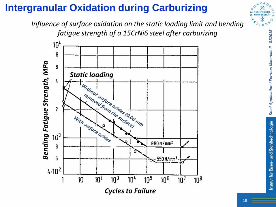
Intergranular Oxidation during Carburizing
Influence of surface oxidation on the static loading limit and bending fatigue strength of a 15CrNi6 steel after carburizing
Cycles to Failure
Ben
din
g F
ati
gu
e St
ren
gth
, MP
a
Static loading

Ste
el A
pp
licati
on
/ F
err
ou
s M
ate
rials
II S
S2015
19
Intergranular Oxidation during Carburizing
AISI 8620 (0.2%C, 0.92% Mn, 0.50% Cr, 0.38% Ni, and 0.16% Mo): non-martensitic product formation due to oxidation in carburized 8620 steel with a relatively low hardenability AISI 4615 (0.2%C, 0.52% Mn, 0.12% Cr, 1.75% Ni, and 0.54% Mo): martensite at surface due to the presence of high Mo and Ni concentrations
Fatigue strength Residual stresses
Co
mp
ress
ive
Ten
sile

Ste
el A
pp
licati
on
/ F
err
ou
s M
ate
rials
II S
S2015
20
Vacuum Carburizing
Vacuum carburizing is a state-of-the-art thermal process where carburizing is done under very low pressures. First the parts are heated in vacuum to above the transformation temperature of the alloy. Then they are exposed to carbon-carrying gas, or gas mixtures, under partial pressure. Relative to conventional carburizing, the main advantages of the method are better control of the surface layer chemistry and thereby improved fatigue strength.
Intergranular oxidation

Ste
el A
pp
licati
on
/ F
err
ou
s M
ate
rials
II S
S2015
21
Alloy Carbide Formation
Effect of Cr content on the carbon content of steels after carburizing. In presence of carbide forming elements such as Cr, some of the carbon introduced by carburizing may form alloy carbides.
Chromium Content, mass-%
Ca
rbo
n C
on
ten
t a
t Su
rfa
ce, m
ass
-% Carburizing conditions
Pu
re ir
on

Ste
el A
pp
licati
on
/ F
err
ou
s M
ate
rials
II S
S2015
22
Residual Stresses
Schematic diagram of residual stresses in carburized steels; surface
compressive stresses are balanced by interior tensile stresses.
Measured and estimated residual stresses as a function of distance through the
thickness of carburized and uncarburized steel specimens
L
R

Ste
el A
pp
licati
on
/ F
err
ou
s M
ate
rials
II S
S2015
23
Residual Stresses
Shot peening can increase the surface residual stresses developed by carburizing of 16MnCr 5 steel (1.23%Mn, 1.08%Cr) and improve its fatigue strength.
Ste
el A
pp
licati
on
/ F
err
ou
s M
ate
rials
II S
S2015
24
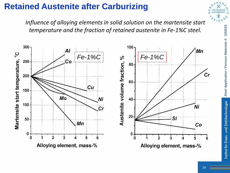
Retained Austenite after Carburizing
Influence of alloying elements in solid solution on the martensite start temperature and the fraction of retained austenite in Fe-1%C steel.
Fe-1%C Fe-1%C

Ste
el A
pp
licati
on
/ F
err
ou
s M
ate
rials
II S
S2015
25
Fatigue Strength
The effect of reheating after carburizing, on the fatigue resistance of a carburized coarse-grained 8620 steel. All specimens were chemically polished. Therefore, the influence of intergranular oxidation on fatigue cracking was removed from the study.
Coarse structure, high density of microcracks
Lower density of surface microcracks, finer martensitic structure, higher hardness, and reduced retained austenite fraction

Ste
el A
pp
licati
on
/ F
err
ou
s M
ate
rials
II S
S2015
26
Fatigue Strength
The effect of austenite grain size and retained austenite content, controlled by reheating after carburizing, on the fatigue strength of 8719 steel. Finer austenite grain size and reduced fraction of retained austenite achieved by reheating to lower austenitization temperatures after carburizing contribute to the fatigue strength.
Gas carburizing
Direct quench
Gas carburizing
Single reheat
Plasma carburizing
Direct quench
Plasma carburizing
Single reheat

Ste
el A
pp
licati
on
/ F
err
ou
s M
ate
rials
II S
S2015
27
Fatigue Strength
Fatigue limit as a function of austenite grain size of 8719 steel carburized and
hardened as indicated
Fatigue limit as a function of retained austenite content in
8719 steel carburized and hardened as indicated

Ste
el A
pp
licati
on
/ F
err
ou
s M
ate
rials
II S
S2015
28
Fatigue Strength
Fatigue limit as a function of austenite grain size and retained austenite content of carburized 8719 steel

Ste
el A
pp
licati
on
/ F
err
ou
s M
ate
rials
II S
S2015
29
The role of retained austenite in the carburized layer on the fatigue strength (positive or negative) depends on factors such as the chemical composition of retained austenite, type of loading, and pre-stressing.
Cycles to Failure
Stre
ss, M
Pa
Retained no tempering
Retained
No retained
(601 HRC)
Retained , rolled with a pressing force of 1400 N
Scatter band for retained , shot peened
Scatter band for no retained , shot peened
(601 HRC)
Fatigue Strength

Ste
el A
pp
licati
on
/ F
err
ou
s M
ate
rials
II S
S2015
30
Reheating
Retained austenite, measured by X-ray diffraction, as a function of distance from the surface of carburized 8620 steel. Reduction of retained austenite takes place by reheating below Acm temperature where the formation of undissolved carbides increases the martensite start temperature.

Ste
el A
pp
licati
on
/ F
err
ou
s M
ate
rials
II S
S2015
31
Reheating Hardness profile near surface of a 16MnCr 5 steel after salt bath carburizing
at different temperatures with or without a single reheat at 825 °C.
Carburizing temperature: Distance from Surface, mm
Carburizing Time V
icke
rs H
ard
nes
s, H
V0
.5 Direct Quench
Single Reheat
Base (core) hardness

Ste
el A
pp
licati
on
/ F
err
ou
s M
ate
rials
II S
S2015
32
Nitriding
Gas nitriding is a case-hardening process whereby nitrogen is introduced into the surface of a solid ferrous alloy by holding the metal at a suitable temperature below (Ac1) in contact with a nitrogenous gas, usually ammonia. Quenching is not required for the production of a hard case. The nitriding temperature for all steels is between 495 °C and 565 °C. Principal reasons for nitriding are:
To obtain a high surface hardness To improve:
• wear resistance and anti-galling properties • fatigue life • corrosion resistance (except for stainless steels)
To obtain a surface that is resistant to the softening effect of heat at temperatures up to the nitriding temperature

Ste
el A
pp
licati
on
/ F
err
ou
s M
ate
rials
II S
S2015
33
Nitriding Sequence

Ste
el A
pp
licati
on
/ F
err
ou
s M
ate
rials
II S
S2015
34
Steels for Nitriding
Of the alloying elements commonly used in commercial steels, Al, Cr, V, W, and Mo are beneficial in nitriding because they form nitrides that are stable at nitriding temperatures. Mo, in addition to its contribution as a nitride former, also reduces the risk of embrittlement at nitriding temperatures. Other alloying elements, such as Ni, Cu, Si, and Mn have little effect on nitriding characteristics. Although at suitable temperatures all steels are capable of forming iron nitrides in the presence of nascent (atomic) nitrogen, the nitriding results are more favorable in those steels that contain one or more of the major nitride-forming alloying elements. Because Al is the strongest nitride former of the common alloying elements, Al-containing steels (0.85 to 1.50% Al) yield the best nitriding results. Cr-containing steels can approximate these results if the Cr content is high enough. Unalloyed carbon steels are not well suited for gas nitriding because they form an extremely brittle case that spalls readily, and the hardness increase in the diffusion zone is small.

Ste
el A
pp
licati
on
/ F
err
ou
s M
ate
rials
II S
S2015
35
Iron Nitrides
Iron carbides (binary Fe-N system)

Ste
el A
pp
licati
on
/ F
err
ou
s M
ate
rials
II S
S2015
36
Iron Nitrides
Ammonia concentrations in ammonia-hydrogen mixtures and temperature ranges
for the formation of various Fe-N phases.

Ste
el A
pp
licati
on
/ F
err
ou
s M
ate
rials
II S
S2015
37
Alloy Nitrides
Influence of some important alloying elements on the nitriding response (surface hardness after gas nitriding) of steel. Presence of nitride-forming elements increases hardness after nitriding.
Alloying Element Content, mass-% Cr Content, mass-%
Bri
nel
l Ha
rdn
ess
Vic
kers
Ha
rdn
ess
Steel with 1%Al
CrMoV steels
Cr(Mo) steels
Nitriding at 500 °C for 84 hrs (in NH3)

Ste
el A
pp
licati
on
/ F
err
ou
s M
ate
rials
II S
S2015
38
Carbonitriding
A modified form of gas carburizing rather than a form of nitriding A mixture of (ammonia + carburizing atmosphere) Typically done at a lower temperature and for a shorter time than gas carburizing,
producing a shallower case than is usual in carburizing Hard, wear-resistant case, generally from 0.075 to 0.75 mm deep Better hardenability than a carburized case (nitrogen increases the hardenability of
steel); a hardened case can be produced at a lower cost. Full hardness with less distortion can be achieved with oil quenching, or, in some
instances, even gas quenching, employing a protective atmosphere as the quenching medium.
Commonly applied to steels containing up to about 0.25 mass-%C. Many steels with a carbon range of 0.30 to 0.50% are carbonitrided to case depths
up to about 0.3 mm when a combination of a reasonably tough, through-hardened core and a hard, long-wearing surface is required (shafts and transmission gears are typical examples).
Applied at 845 °C to such steels as 4140, 5130, 5140, 8640, and 4340 for applications like heavy-duty gearing.

Ste
el A
pp
licati
on
/ F
err
ou
s M
ate
rials
II S
S2015
39
Carbonitriding
One major advantage of carbonitriding is that the nitrogen absorbed during processing lowers the critical cooling rate of the steel. That is, the hardenability of the case is significantly greater when nitrogen is added by carbonitriding than when the same steel is only carburized. This permits the use of steels on which uniform case hardness ordinarily could not be obtained if they were only carburized and quenched. Where core properties are not important, carbonitriding permits the use of low-carbon steels, which cost less and may have better machinability or formability.
End-quench hardenability curve for 1020 steel carbonitrided at 900 °C (1650 °F) compared with curve for the same steel carburized at 925 °C (1700 °F). Hardness was measured along the surface of the as-quenched hardenability specimen. Ammonia and methane contents of the inlet carbonitriding atmosphere were 5%; balance: carrier gas.

Ste
el A
pp
licati
on
/ F
err
ou
s M
ate
rials
II S
S2015
40
Carbonitriding
The amount of retained austenite was reduced by: - lowering the ammonia flow rate/content of the atmosphere - introducing a 15-min diffusion period at the end of the carbonitriding operation.
Hardness profiles in a 1117 steel carbonitrided at 815 °C for 1.5 hrs and quenched in oil
High retained
austenite content
at surface

Ste
el A
pp
licati
on
/ F
err
ou
s M
ate
rials
II S
S2015
41
Diffusion Treatment Characteristics Process Nature of case Process
temperature, °C Typical case depth
Case hardness, HRC
Typical base metals Process characteristics
Carburizing Pack Diffused carbon 815-1090 125 µm-1.5
mm 50-63 Low C steels, low-C
alloy steels Low equipment costs, difficult to control case depth accurately
Gas Diffused carbon 815-980 75 µm-1.5 mm 50-63 Low C steels, low-C alloy steels
Good control of case depth, suitable for continuous operation, good gas controls required, can be dangerous
Liquid Diffused carbon and possibly nitrogen
815-980 50 µm-1.5 mm 50-65 Low C steels, low-C alloy steels
Faster than pack and gas processes, can pose salt disposal problem, salt baths require frequent maintenance
Vacuum Diffused carbon 850-1090 75 µm-1.5 mm 50-63 Low C steels, low-C alloy steels
Excellent process control, bright parts, faster than gas carburizing, high equipment costs
Nitriding Gas Diffused
nitrogen, nitrogen compounds
510-565 125 µm-0.75 mm
50-70 Alloy steels, nitriding steels, stainless steels
Hardest cases from nitriding steels, quenching not required, low distortion, process is slow, is usually a batch process
Salt Diffused nitrogen, nitrogen compounds
510-565 2.5 µm-0.75 mm
50-70 Most ferrous metals including cast irons
Usually used for thin hard cases below 25 µm, no white layer, most are proprietary processes
Ion Diffused nitrogen, nitrogen compounds
340-565 75 µm-0.75 mm
50-70 Alloy steels, nitriding steels, stainless steels
Faster than gas nitriding, no white layer, high equipment costs, close case control
Carbo-nitriding Gas Diffused carbon
and nitrogen 760-870 75 µm-0.75
mm 50-65 Low C steels, low-C
alloy steels, stainless steels
Lower temperatures than carburizing (less distortion), slightly harder case than carburizing, gas control critical
Liquid (cyaniding)
Diffused carbon and nitrogen
760-870 2.5-125 µm 50-65 Low C steels Good for thin cases on noncritical parts, batch process, salt disposal problems
Ferritic nitro-carburizing
Diffused carbon and nitrogen
480-590 2.5-25 µm 40-60 Low C steels Low-distortion process for thin case on low-carbon steel, most processes are proprietary

Ste
el A
pp
licati
on
/ F
err
ou
s M
ate
rials
II S
S2015
42

![Surface Hardening of Stainless Steels - · PDF fileof the surface with hardening species ... Process methods for the surface hardening of steels [7] ... in: International Heat Treatment](https://static.fdocuments.net/doc/165x107/5ab1f2327f8b9aea528d035c/surface-hardening-of-stainless-steels-the-surface-with-hardening-species-process.jpg)


![Surface Hardening of Stainless · PDF fileOutokumpu Associated members ... Process methods for the surface hardening of steels [7] ... applied to duplex and precipitation hardening](https://static.fdocuments.net/doc/165x107/5a76d0557f8b9a1b688d8c0a/surface-hardening-of-stainless-steels-a-outokumpu-associated-members-process.jpg)


