Steel Column Design - · PDF fileSteel Column Design ... of the specifications covers double...
15
PDHonline Course S216 (3 PDH) Steel Column Design 2012 Instructor: Matthew Stuart, PE, SE PDH Online | PDH Center 5272 Meadow Estates Drive Fairfax, VA 22030-6658 Phone & Fax: 703-988-0088 www.PDHonline.org www.PDHcenter.com An Approved Continuing Education Provider
Transcript of Steel Column Design - · PDF fileSteel Column Design ... of the specifications covers double...

PDHonline Course S216 (3 PDH)
Steel Column Design
2012
Instructor: Matthew Stuart, PE, SE
PDH Online | PDH Center5272 Meadow Estates Drive
Fairfax, VA 22030-6658Phone & Fax: 703-988-0088
www.PDHonline.orgwww.PDHcenter.com
An Approved Continuing Education Provider
www.PDHcenter.com PDH Course S216 www.PDHonline.org
© D. Matthew Stuart Page 2 of 15
Steel Column Design
D. Matthew Stuart, P.E., S.E., F.ASCE, SECB
COURSE CONTENT
Columns
Axial Loaded Members: The capacity of an axially loaded slender member in compression is governed by the critical buckling load (Pcr), however, for extremely stocky members compression failure may occur via yielding rather than buckling. The formula for calculating Pcr, developed by Euler, for a column pinned at each end with no intermediate brace points, and no load eccentricities is;
Pcr = π2EI/L2 = π2EA/(L/r) 2
Where: L = unbraced length; A = cross sectional area; r = radius of gyration If the critical buckling load is divided by the area of a given member the critical buckling stress is obtained as;
Fcr = Pcr/A = π2E/(L/r) 2
For less slender, or stocky, members E is replaced by Et (Tangent Modulus) to account for the non-linear relationship between stress an strain that results because the relative small slenderness ratio (L/r) for these types of members results in large buckling stress values that are greater than the proportional limit of the material. Et is smaller than E and because of its variability the calculation of Pcr in the inelastic range is difficult and requires a trial and error approach. For this reason the AISC design specifications contain empirical formulas for inelastic columns. The critical buckling stress can be plotted as a function of the slenderness ratio as shown in Figure 1.
FIGURE 1
www.PDHcenter.com PDH Course S216 www.PDHonline.org
© D. Matthew Stuart Page 3 of 15
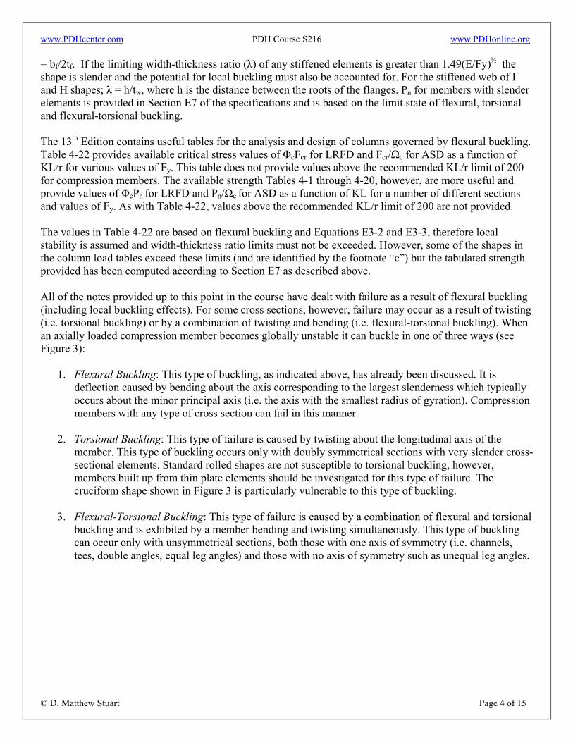
End conditions other than pinned/pinned are accounted for by the use of K, the effective length factor. Modifying the critical buckling stress (Fcr) using K results in the elastic buckling stress; Fe = π2E/(KL/r)2 = Pe/Ag; where Pe = the buckling load and Ag = the gross area of the section. Values of K for isolated columns that are not a part of a continuous frame are provided in Table C-C2.2 of the 13th Edition on page 16.1-240. To determine the K factors for columns that form a part of a frame with rigid joints, alignment charts are provided on page 16.1-241 and 16.1-242 for sidesway inhibited (i.e. braced) and sidesway uninhibited (i.e. moment frame) conditions, respectively. It should be noted that when using the referenced alignment charts G = 10.0 for a pinned foundation support and G = 1.0 for a fixed foundation support. Also, in a braced frame the beam-to-column connections are not normally detailed or constructed as moment resisting because the bracing system is designed to resist all lateral loads independent of the surrounding unbraced beam/column bents. In this scenario there is no continuity between the beams and columns and the alignment charts cannot be used. For this type of braced frame K = 1.0. It should also be noted that if the slenderness ratio, KL/r is less than 4.71(E/Fy)½ the column will buckle inelastically and the K factors obtained from the alignment charts will be overly conservative. A procedure for determining K for inelastic columns that allows for the use of the alignment charts can be found on page 16.1-247 of the 13th Edition Commentary. This method involves the use of a stiffness reduction factor (τa), which is used to modify Fe = Pe2/ τaAg; where Pe2 = elastic critical buckling load. This value of Fe is then used to determine Fcr for the purposes of calculating the nominal compression strength (Pn) in Section E3 of the AISC Specifications. The requirements for compression members in the 13th Edition, Chapter E, list the nominal compression strength; Pn = FcrAg. For LRFD Pu ≤ ΦPn (where the resistance factor Φ = 0.90 for compression members) and for ASD (Allowable Strength Design) Pa ≤ Pn/Ω (where the safety factor Ω = 1.67 for compression members). For compact and non-compact compression members (without slenderness elements) per Section E3 of the specifications; Pn = FcrAg (based on the limit state of flexural buckling). Fcr is defined by Equations E3-2 and E3-3 on page 16.1-33 as determined by whether Kl/r is less than or equal to 4.71(E/Fy)½ (i.e. inelastic buckling) or greater than 4.71(E/Fy)½. The variation in Fcr is represented in Figure 2.
FIGURE 2
The compression strength of a member based on the above buckling mode cannot be developed if the elements of the member’s cross section are so thin that local buckling can occur. If the limiting width-thickness ratio (λ) of any unstiffened elements is greater than 0.56(E/Fy)½ the shape is slender and the potential for local buckling must be accounted for. For the projecting unstiffened flange of I and H shapes; λ
www.PDHcenter.com PDH Course S216 www.PDHonline.org
© D. Matthew Stuart Page 4 of 15
= bf/2tf. If the limiting width-thickness ratio (λ) of any stiffened elements is greater than 1.49(E/Fy)½ the shape is slender and the potential for local buckling must also be accounted for. For the stiffened web of I and H shapes; λ = h/tw, where h is the distance between the roots of the flanges. Pn for members with slender elements is provided in Section E7 of the specifications and is based on the limit state of flexural, torsional and flexural-torsional buckling. The 13th Edition contains useful tables for the analysis and design of columns governed by flexural buckling. Table 4-22 provides available critical stress values of ΦcFcr for LRFD and Fcr/Ωc for ASD as a function of KL/r for various values of Fy. This table does not provide values above the recommended KL/r limit of 200 for compression members. The available strength Tables 4-1 through 4-20, however, are more useful and provide values of ΦcPn for LRFD and Pn/Ωc for ASD as a function of KL for a number of different sections and values of Fy. As with Table 4-22, values above the recommended KL/r limit of 200 are not provided. The values in Table 4-22 are based on flexural buckling and Equations E3-2 and E3-3, therefore local stability is assumed and width-thickness ratio limits must not be exceeded. However, some of the shapes in the column load tables exceed these limits (and are identified by the footnote “c”) but the tabulated strength provided has been computed according to Section E7 as described above. All of the notes provided up to this point in the course have dealt with failure as a result of flexural buckling (including local buckling effects). For some cross sections, however, failure may occur as a result of twisting (i.e. torsional buckling) or by a combination of twisting and bending (i.e. flexural-torsional buckling). When an axially loaded compression member becomes globally unstable it can buckle in one of three ways (see Figure 3):
1. Flexural Buckling: This type of buckling, as indicated above, has already been discussed. It is deflection caused by bending about the axis corresponding to the largest slenderness which typically occurs about the minor principal axis (i.e. the axis with the smallest radius of gyration). Compression members with any type of cross section can fail in this manner.
2. Torsional Buckling: This type of failure is caused by twisting about the longitudinal axis of the
member. This type of buckling occurs only with doubly symmetrical sections with very slender cross-sectional elements. Standard rolled shapes are not susceptible to torsional buckling, however, members built up from thin plate elements should be investigated for this type of failure. The cruciform shape shown in Figure 3 is particularly vulnerable to this type of buckling.
3. Flexural-Torsional Buckling: This type of failure is caused by a combination of flexural and torsional
buckling and is exhibited by a member bending and twisting simultaneously. This type of buckling can occur only with unsymmetrical sections, both those with one axis of symmetry (i.e. channels, tees, double angles, equal leg angles) and those with no axis of symmetry such as unequal leg angles.

www.PDHcenter.com PDH Course S216 www.PDHonline.org
© D. Matthew Stuart Page 5 of 15
FIGURE 3
Section E4(a) of the specifications covers double angle and tee shaped members. Section E4(b) provides a more general approach that can be used for any shape. As with the analysis and design of compression members subjected to flexural buckling, the strength of most double angles and tees that are subject to flexural-torsional buckling can be found in the column load tables of the 13th Edition. These tables give two sets of values of the available strength; one based on flexural buckling about the x-axis and one based on flexural-torsional buckling about the y-axis (as provided by Section E4(a)). Available compression strength tables are also provided for single angle members. The values provided for these members are based on the provisions of Section E5 only.
Combined Bending and Axial Loaded Members:
The categories of combined bending and axial loading (along with the likely mode of failure) include:
1. Axial tension and bending; failure by yielding. 2. Axial compression and bending about one axis; failure by instability in the plane of bending without
twisting.
3. Axial compression and bending about the strong axis; failure by lateral torsional buckling.
4. Axial compression and biaxial bending (torsional stiff sections); failure by instability in one of the principal directions.
5. Axial compression and biaxial bending (thin-walled sections); failure by combined twisting and
bending.
6. Axial compression, biaxial bending and torsion; failure by combined twisting and bending when plane of bending does not include the shear center.
The provisions for the design and analysis of members subjected to combined bending and axial forces are provided in Chapter H of the 13th Edition. In general this Chapter provides interaction equations for axial and

www.PDHcenter.com PDH Course S216 www.PDHonline.org
© D. Matthew Stuart Page 6 of 15
bending strengths (i.e. required strength/available strength ≤ 1.0) that in combination have to be less than or equal to 1.0. The above approach to the design of combined bending and axial loads is satisfactory as long as the axial load is not too large. This is because the presence of an axial load produces secondary moments as a result of the deflection caused from the flexural buckling, which must be accounted for unless the axial load is relatively small. See Appendix 7 of the 13th Edition (page 16.1-196) for guidance concerning the axial load limit. It should be noted that pinned end columns with no lateral load or applied end moment will not have any secondary effects, therefore Table 4-22 provides the appropriate values from equations E3-2 and E3-3 with the required safety and resistance factors for use in calculating of the available axial strength of a column. An example of the impact of this secondary effect is shown in Figure 4. For this example the secondary moment is largest where the deflection of the column is the largest, in this case at mid-height, where the total moment = wL2/8 + Pδ. This combined moment results in even more deflection over and above that resulting from the transverse load, however the total deflection cannot be found directly because of the non-linear nature of the condition.
FIGURE 4
Ordinary structural analysis methods that do not take into account the displaced geometry described above are referred to as first-order methods. Iterative numerical techniques, referred to as second-order methods, can be used to find the defections and secondary moments, however these methods are impractical for manual calculations and are usually only available via a computer program. Most current building codes, including the AISC Specifications, permit the use of second-order analysis or an alternate approach referred to as a moment magnification method. This later method involves computing the maximum bending moments resulting from the flexural loading using first-order analysis methods then multiplying the result by a moment magnification or amplification factor to account for the secondary moment. Chapter C of the 13th Edition provides the methods of moment amplification for steel members. Two amplification factors are provided in this Chapter; one to account for amplification resulting for the member deflection and one to account for the effect of sway when the member is a part of an unbraced frame. This approach is very similar to the methods used in ACI 318-05 for reinforced concrete design. For LRFD the amplification factor = 1/(1 – (Pu/Pe)). For members in a braced frame (i.e. where no sway can occur and the ends of the column cannot translate with respect to one another) there are two conditions that can occur: Single Curvature bending (see Figure 5); where the maximum moment amplification occurs at the center where the deflection is the largest, and

www.PDHcenter.com PDH Course S216 www.PDHonline.org
© D. Matthew Stuart Page 7 of 15
Reverse Curvature bending (see Figure 6); where the maximum primary moment is at one of the ends of the column and the maximum amplification occurs between the two ends.
FIGURE 5 FIGURE 6 The maximum moment in a beam-column therefore depends on the distribution of the bending moment within the member. This distribution is accounted for by a factor Cm, which is applied to the amplification factor (B1) such that;
B1 = Cm/(1 – (αPr/Pe1)) ≥ 1.0 (AISC Equation C2-2)
Where: Pr = the required axial compression strength = Pu for LRFD; = Pa for ASD α = 1.0 for LRFD; = 1.60 for ASD Pe1 = π2EI/(K1L)2 Note that subscripts in the equations provide in Chapter H are 1 for a braced condition and 2 for an unbraced condition. Also, the factor Cm applies only to braced conditions. Values of Cm in Chapter H are provided for two conditions; one where there is a transverse load applied between the ends of the member, and another where there is no transverse loading between the ends. The values for Cm for these two conditions are provided in Equations C2-4 (page 16.1-22) and C-C2-2 (page 16.1-235), respectively. The later equation is provided only if a more refined analysis is required, otherwise Cm = 1.0. For beam-column members in unbraced frames in which the ends of the columns are free to translate the maximum primary moment resulting from the effects of the sidesway almost always occur at one end of the member. In addition, the maximum secondary moment in an unbraced frame always occurs at the member end. As a result of this condition, the maximum primary and secondary moments are usually additive and there is no need for a Cm factor. The moment amplification factor for unbraced frames (B2) is provide in Equation C2-3 of the 13th Edition (page 16.1-21). The rationale for using the summation of the Pe2 and Pnt (the first order axial force assuming no lateral sidesway) in the equation for B2 is that if sidesway is going to occur all columns in that story of the building must sway simultaneously. For a further discussion of the related topic of Leaner Columns, see Leaner Columns Course S121.
Column Stiffeners and Other Reinforcement: Most of the moment transferred from a beam to a column in a rigid connection involves a force-couple consisting of tensile and compressive stresses in the beam flanges that result in the application of large concentrated loads to the column. This condition typically requires that the column be reinforced to avoid local buckling. For the condition represented in Figure 7, the applied negative moment from the beam results

www.PDHcenter.com PDH Course S216 www.PDHonline.org
© D. Matthew Stuart Page 8 of 15
in concentrated flanges forces (tension in the top and compression in the bottom) being transmitted to the column web via the column flanges. To prevent distortion of the column flange (for the tension condition) and buckling of the column web (for the compression condition) web stiffeners are typically added
Figure 7
Section J10 of the 13th Edition provides the basis for determining if stiffeners are required for forces applied normal to the flanges of a wide flange section. Specific local condition checks included in this section of the AISC Specifications are (with the exception of Web Sidesway Bucking – see Section J10.4):
1. Local Bending of the Column Flange: To avoid local bending failure of the column flange the tensile load applied from the beam flange must not exceed the nominal strength;
Rn = 6.25tf
2Fyf
Where: tf = thickness of the column flange Fyf = yield stress of the column flange
For LRFD, the design strength = ΦRn, where Φ = 0.90. For ASD the allowable strength = Rn/Ω,
where Ω = 1.67. It should also be noted that if the beam flange tensile load is applied at a distance less than 10tf from the end of the column, the nominal strength must be reduced by 50%.
2. Local Web Yielding: The available web strength due to compression yielding for loads applied at a
distance from the end of the column that is more than the depth of the column;
Rn = (5k + N)Fywtw
If the load is applied at a distance from the end of the column that is less than the depth of the column;
Rn = (2.5k + N)Fywtw
Where: k = the distance from the outer flange surface of the column to the toe of the fillet of the column web
N = length of the applied load = thickness of the beam flange or flange plate Fyw = yield stress of the column web tw = thickness of column web

www.PDHcenter.com PDH Course S216 www.PDHonline.org
© D. Matthew Stuart Page 9 of 15
For LRFD, the design strength = ΦRn, where Φ = 1.00. For ASD the allowable strength = Rn/Ω, where Ω = 1.50.
3. Web Crippling: To prevent web crippling when the compressive load is applied to one flange only (as
in the case with an exterior column with a beam connected to one side only) the applied load must not exceed the available strength provided by Equation J10-4 (page 16.1-117), where d = the total column depth. If the load is applied less than d/2 from the end of the column then Equation J10-5a or J10-5a controls (depending on the relationship of N/d). For LRFD, the design strength = ΦRn, where Φ = 0.75. For ASD the allowable strength = Rn/Ω, where Ω = 2.00.
4. Web Compression Buckling: Compression buckling of the column web must be investigated when the loads are delivered to both column flanges (as in the case of an interior column with beams on both sides of the column). The nominal strength for this limit case is provided by Equation J10-8 (page 16.1-119), where h = the column web depth from toe to toe of the flange fillets. If the applied load is within a distance d/2 from the end of the column, the strength must be reduced by 50%. For LRFD, the design strength = ΦRn, where Φ = 0.90. For ASD the allowable strength = Rn/Ω, where Ω = 1.67.
5. Web Panel Zone Shear: The transfer of large moments to a column can produce large shearing
stresses in the column web within the boundaries of the connection. This region is usually defined as the “panel zone” as represented in Figure 8. The nominal web shear strength for this condition is provided by Equation J10-9 (page 16.1-119) or J10-10 (depending on the relationship of Pr and 0.4Pc). Equation J10-11 is provided for plastic deformation of the panel zone when frame stability is considered as a part of the analysis. For LRFD, the design strength = ΦRn, where Φ = 0.90. For ASD the allowable strength = Rn/Ω, where Ω = 1.67.
FIGURE 8
If the required strength is greater than the available strength for any of the above limit states, column web stiffener plates must be provided. The nominal strength provided by a stiffener plate = FystAst, where Fyst = the yield stress of the stiffener and Ast = the area of the stiffener. For LRFD, the design strength of the stiffener is equated to the extra strength needed with the required area of the stiffener solved for as;

www.PDHcenter.com PDH Course S216 www.PDHonline.org
© D. Matthew Stuart Page 10 of 15
Ast = (Pbf – ΦRn min)/ΦstFyst
Where: Φst = 0.90 Pbf = applied factored load from the beam flange or flange plate ΦRn min = the lesser of the strengths corresponding to local failure modes described above. For ASD, the allowable strength of the stiffener is equated to the extra strength needed with the area of the required stiffener solved for as;
Ast = (Pbf – (Rn/Ω)min)/Fyst/Ωst
Where: Ωst = 1.67 For column webs with insufficient panel zone shear strength it is more common to add a doubler plate, a diagonal stiffener or increase the column size to a section with a thicker web. Section J10.8 (page 16.1-120) provides guidelines for the proportioning of stiffener plates.
Additional guidelines can also be found in AISC Design Guide 13; Wide-Flange Column Stiffening at Moment Connections. Base Plates and Anchor Rods The design of column base plates subjected to axial compression is fairly straight forward. The design of compression only base plates involves:
1. Determining the minimum area of the base plate as controlled by the bearing strength of the concrete (or grout) under the steel.
2. Determining the thickness of the plate as controlled by the bending strength of the plate.
The allowable bearing strength of concrete is governed by Section 10.17 of ACI 318-05. The design bearing strength of concrete shall not exceed; Φ(0.85fc’A1); where Φ = 0.65 and A1 = the loaded or bearing area. When the supporting surface of the concrete is wider on all sides than the loaded area, then the design strength can be increased by the ratio (A2/A1)½, but not more than 2.0; where A2 is as shown in Figure 9.

www.PDHcenter.com PDH Course S216 www.PDHonline.org
© D. Matthew Stuart Page 11 of 15
FIGURE 9
The methods of calculating the minimum base plate thickness are provided on page 14-6 of the 13th Edition as;
The calculation of a base plate subjected to both compression and overturning moment is somewhat more complicated in that the situation is similar to the derivation of the soil bearing stress under a footing subjected to an axial load and overturning moment because the grout or concrete under a base plate cannot resist any tension in the same way that soil cannot resist any tensile stresses. The difference with a base plate, however, is that the tensile force induced by the overturning moment is resisted by anchor rods (formally referred to as anchor bolts). There are a number of different methods available for the analysis of base plates subjected to axial loads and overturning moments. Some are based on elastic analysis and some are based on limit state or ultimate strength analysis. An example of an ultimate strength approach is provided in Calculating Service Moment Capacity of Anchor Bolted Connections; Practice Periodical on Structural Design and Construction; February 1999. Other resources include the AISC Design Guide #1; Base Plate and Anchor Rod Design, unfortunately the 3rd Edition of this publication is being developed right now and as a result the 2nd Edition is no longer available on line. Another practical approach referenced by Steel Structures Design and Behavior, 4th Edition is that provided by Omar Blodgett in the Design of Welded Structures. Anchor rod material is covered under the ASTM F1554 specification which was introduced in 1999. This specification is the first time that hooked, headed, threaded, and nutted rods in multiple grades of materials were fully addressed in one specification. Prior to ASTM F1554, A36 and A307 bolts were the most common type of material to be specified for anchor rods. ASTM F1554 rods are available in three grades; 36

www.PDHcenter.com PDH Course S216 www.PDHonline.org
© D. Matthew Stuart Page 12 of 15
ksi, 55 ksi and 105 ksi. Different grades of rods are identified by color; 36 is blue, 55 is yellow and 105 is red. Grade 36 is the most commonly specified and has a tensile strength of 58 ksi and comes in sizes up to 4 inches in diameter which are all weldable. Grade 55 has a 75 ksi tensile strength and is also available up to 4 inches in diameter. Weldablity Supplement S1 and the carbon equivalent formula in Section S1.5.2.1 of ASTM F1554 can be specified to allow for welded field corrections of this grade of rod. Grade 105 has a tensile strength or 125 ksi and comes in sizes up to 3 inches in diameter. All three grades of rods are suitable for galvanizing by either a hot-dip process (ASTM A153 Class C) or a mechanical process (ASTM B695 Class 50). It should be noted that the same galvanizing process used for the rods should also be used for the nuts to assure proper matching of the threads. Appropriate ASTM A563 nuts for the various grades of rods are provided in Section 6.6.1 of ASTM F1554. Threads for ASTM F1554 rods can be made by either rolling or cutting. Rolled and cut threaded rods have the same strength (because the stress area remains the same for each), however, the elongation of the rods with rolled threads and cut threads will differ. This is because a rolled threaded rod has about 14% less resistance to elongation because the minimum body diameter of a rolled thread is 0.9067 inches (for a 1 inch diameter rod) while the minimum body diameter of a cut thread rod is 0.9755 inches (for a 1 inch diameter rod). The design requirements for anchor rods embedded in concrete are covered under Appendix D of ACI 318-05. This portion of the Code covers both cast-in (i.e. headed, and threaded and nutted) and post-installed (i.e. drilled and epoxied, undercut or wedge) anchors. Basically the tensile capacity of an anchor rod, as controlled by concrete, is based on the resistance provided by the pullout cone similar to that shown on page 14-11 of the 13th Edition (see Figure 10). Similar cones of concrete resistance are also used to establish the shear capacity of an anchor rod when it is located next to the edge of the concrete. The tensile cone of concrete is engaged by the anchor rod either by bearing from a headed stud or nut and or washer located at the base of the rod. In addition, it is also possible to engage the concrete cone via the deformations of an all-threaded rod through mechanical anchorage with the concrete. Shear from an anchor rod is transmitted to the concrete via bearing. It should be noted that because of the typical close spacing of anchor rods, it is common for the cones of concrete resistance to over lap. Appendix D includes provisions for the methods of calculating the equivalent cones of resistance for groups of closely spaced rods.
FIGURE 10

www.PDHcenter.com PDH Course S216 www.PDHonline.org
© D. Matthew Stuart Page 13 of 15
Although hooked rods are allowed in Appendix D, the use of hooked anchors is not recommended for two reasons; first the rods (if smooth) can be physically pulled out of the concrete if enough tensile force is applied to the anchor, and secondly these type of rods have been known to fail prematurely at the cold bend of the hook. It is also recommended that only epoxied anchor rods be used for post-installed applications that are subjected to cyclical loads. This is because the other types of post-installed anchors (wedge and undercut) are susceptible to loosening under repeated cyclical loads. Figures 11a and 11b is provided below to illustrate an example of a typical base plate and anchor rod detail for a building. Note that a plate has been attached to the bottom of the anchor rod to help develop the resisting cone of concrete.
FIGURE 11a FIGURE 11b Additional notes and guidelines concerning base plates and anchor rods include:
1. There are four main differences between column base plate/anchor rod connections and other steel framing connections:
a. Anchor rods are installed during the construction of the foundation typically at a point in the
construction administration phase of the project at which the engineer of record and the fabricator may not have communicated. This situation can lead to errors in both the shop drawings and the field installation.
b. Larger anchor rod setting allowances have to be incorporated into the base plate details even
though the installation tolerances are relatively tight (i.e. less than or equal to 1/8 inch between any two anchor rods and less than or equal to ¼ inch between one group of anchor rods and another adjacent group).
c. Anchor rods can be easily damaged by heavy equipment in the field during the construction
phase.
www.PDHcenter.com PDH Course S216 www.PDHonline.org
© D. Matthew Stuart Page 14 of 15
d. If an anchor rod is damaged, the repair and or replacement of the damaged rod can be difficult and expensive. For a discussion of the recommendations for the repair of damaged or misplaced anchor rods see Modern Steel Construction, May 2004.
2. OSHA safety regulations require that all columns be provided with a minimum of four anchor rods.
Satisfying this requirement can be difficult in situations where placement of the column next to a wall makes access difficult or if the allowable architectural constraints of an exposed base plate for a relatively small column make it difficult to conceal the anchor rods.
3. Because of the significant reduction in the allowable tensile strength of anchor rods that occurs with
rods that are also subjected to shear forces, anchor rods should not be used for the transfer of the base shear reaction from the column to the footing. Instead it is recommended that the base shear forces be transferred to the surrounding foundation system via bearing of the embedded portion of the steel column against the surrounding concrete slab. The slab in turn can be used to distribute the shear to other surrounding footings, walls and foundation systems.
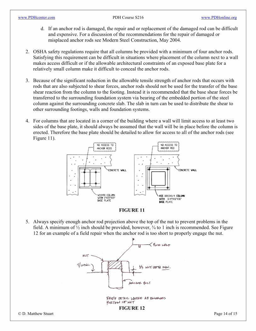
4. For columns that are located in a corner of the building where a wall will limit access to at least two
sides of the base plate, it should always be assumed that the wall will be in place before the column is erected. Therefore the base plate should be detailed to allow for access to all of the anchor rods (see Figure 11).
FIGURE 11
5. Always specify enough anchor rod projection above the top of the nut to prevent problems in the
field. A minimum of ½ inch should be provided, however, ¾ to 1 inch is recommended. See Figure 12 for an example of a field repair when the anchor rod is too short to properly engage the nut.
FIGURE 12

www.PDHcenter.com PDH Course S216 www.PDHonline.org
© D. Matthew Stuart Page 15 of 15
6. The specified grout thickness beneath a base plate should be at least 1½ inches for ¾ inch diameter
anchor rods when using leveling nuts and washers. A minimum of 2 inches of grout should be used if a leveling plate is employed.
7. Extra threaded length of the rod should be specified in case the rod projects to high out of the top of
the concrete. Normally threads are only required to extend just 1 inch below the top of concrete.
8. Avoid specifying a number of different sizes, types and grade of anchor rods on any one project.