Steam Turbine Concepts for the Future Volatile Power Market · Steam Turbine Concepts for the...
19
Steam Turbine Concepts for the Future Volatile Power Market © Siemens AG 2012. All rights reserved. Siemens AG - Energy Sector Fossil Power Generation Power-Gen Europe June 12 – 14, 2012 Michael Wechsung Thomas Loeper Radim Znajda
Transcript of Steam Turbine Concepts for the Future Volatile Power Market · Steam Turbine Concepts for the...

Steam Turbine Concepts for the Future Volatile Power Market
© Siemens AG 2012. All rights reserved.
Siemens AG - Energy SectorFossil Power Generation
Power-Gen EuropeJune 12 – 14, 2012
Michael WechsungThomas LoeperRadim Znajda

Page 2
.
Thomas Loeper, June 2012Power-Gen Europe 2012, Cologne
© Siemens AG 2012. All rights reserved
Agenda
Situation today and tomorrow
Measures
HP stage bypass
Controlled HP feed water heaters bypass
HP feed water top heater
Combination of the measures
Conclusion

Page 3
.
Thomas Loeper, June 2012Power-Gen Europe 2012, Cologne
© Siemens AG 2012. All rights reserved
Facts about Germany’s power market 2011
Hard coal fired power plants
- operating in intermediate load range
- about 3.000 full load operating hours
- providing 19 %+ of electrical power
Renewables
- more than 64 GW+ renewable power installed
- providing 20 %+ of electrical power
Lignite fired power plants
- providing base load
- about 6.000 – 7.000 full load operating hours
- providing 25 %+ of electrical power

Page 4
.
Thomas Loeper, June 2012Power-Gen Europe 2012, Cologne
© Siemens AG 2012. All rights reserved
Tomorrow
Tomorrow (Scenario 2020):
- renewables providing 35 %+ of electrical power
- increase of wind and solar power share
- existing base load will be reduced
This scenario intensifies the situation of thermal power plants.
The increase of electrical power production by renewables
- queries the classical fractions: base, intermediate and peak load
- renewable power and residual load remain

Page 5
.
Thomas Loeper, June 2012Power-Gen Europe 2012, Cologne
© Siemens AG 2012. All rights reserved
Load requirements today and tomorrow
0%
10%
20%
30%
40%
50%
30%
35%
40%
45%
50%
55%
60%
65%
70%
75%
80%
85%
90%
95%
100%
Last
zeitl
iche
r Ant
eil bisher
zukünftig *up to now
tomorrow
Load
Shar
e of
tim
e
Efficiency optimization over a broad load range
Large reserve power capacity

Page 6
.
Thomas Loeper, June 2012Power-Gen Europe 2012, Cologne
© Siemens AG 2012. All rights reserved
HP stage bypass
Stop valve
HP stage bypass valve
Rated condition
Main controlvalves are wideopen
Additional load
is closedopens

Page 7
.
Thomas Loeper, June 2012Power-Gen Europe 2012, Cologne
© Siemens AG 2012. All rights reserved
Power Output: 1040 MWMain Steam: 270 bar / 600 °C Reheat Steam: 600 °CCondenser: 0.053 / 0.042 barFuel type: hard coalComm. Operation: 2008
HP stage bypass
HP stage bypass
10 % - 15 % main steam increase
about 50 MW - 70 MW additional output

Page 8
.
Thomas Loeper, June 2012Power-Gen Europe 2012, Cologne
© Siemens AG 2012. All rights reserved
Controlled HP feed water heaters bypass
Bypass control valve
Feed water control valve
- 30 minutes
- mbypass / mFW = 0.7
- 40 MW add. power

Page 9
.
Thomas Loeper, June 2012Power-Gen Europe 2012, Cologne
© Siemens AG 2012. All rights reserved
Controlled HP feed water heaters bypass
Feed water control valve
Controlled bypass for HP feed water heaters
The Controlled HP feed water heaters bypass needs only small adjustments of pipe routing in the turbine building.
Page 10
.
Thomas Loeper, June 2012Power-Gen Europe 2012, Cologne
© Siemens AG 2012. All rights reserved
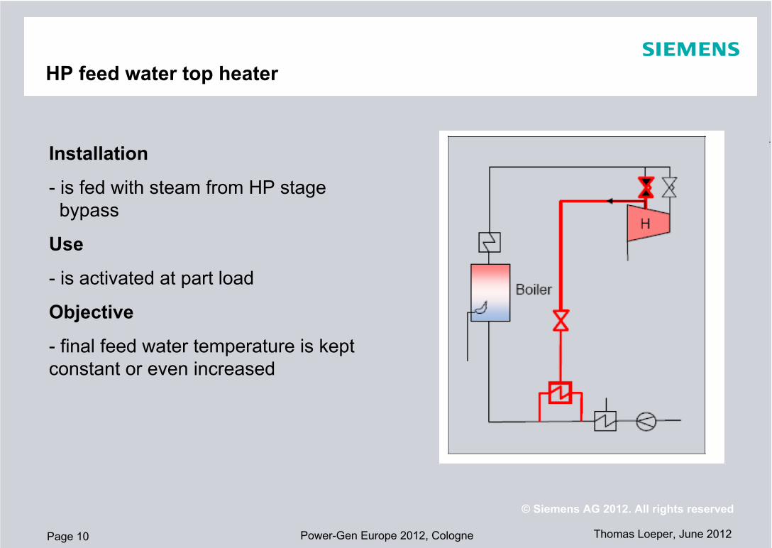
HP feed water top heater
Installation
- is fed with steam from HP stage bypass
Use
- is activated at part load
Objective
- final feed water temperature is kept constant or even increased

Page 11
.
Thomas Loeper, June 2012Power-Gen Europe 2012, Cologne
© Siemens AG 2012. All rights reserved
HP feed water top heater
Top heater concept serves for better part load efficiency.

Page 12
.
Thomas Loeper, June 2012Power-Gen Europe 2012, Cologne
© Siemens AG 2012. All rights reserved
Combination of the measures

Page 13
.
Thomas Loeper, June 2012Power-Gen Europe 2012, Cologne
© Siemens AG 2012. All rights reserved
Combination of the measures
The combination results in proposed design strategy.
Design point
HP stage bypass Controlled HP heaters bypassMS-T and FW-T increase

Page 14
.
Thomas Loeper, June 2012Power-Gen Europe 2012, Cologne
© Siemens AG 2012. All rights reserved
Conclusion
Proposed design strategy depends on plant load profile.
The described measures have to be adapted accordingly.
Ex = 76.75 %

Page 15
.
Thomas Loeper, June 2012Power-Gen Europe 2012, Cologne
© Siemens AG 2012. All rights reserved
Conclusion
The proposed design strategy requires measures to additionally improve operating flexibility:
- Reasonable boiler design also with improved load change rates and parking load concepts
- Control philosophy encompasses thermodynamical models
- Considering life time consumption

Page 16
.
Thomas Loeper, June 2012Power-Gen Europe 2012, Cologne
© Siemens AG 2012. All rights reserved
Conclusion
The proposed design strategy
- ensures lower OPEX by improved part load efficiency
- presents CAPEX reduction potential by smaller design
Proposed design startegy vs. current design
Feed w
ater fl
owFee
d wate
r pum
p pow
erHot
rehea
t stea
m flow
Hot reh
eat s
team vo
lume f
low
Hot reh
eat s
team pr
essu
reLP
-exha
ust fl
ow
Exhau
st are
aHP tu
rbine
power
IP turbi
ne po
werRat
io o
f pro
pose
d an
d cu
rren
t des
ign
1

Page 17
.
Thomas Loeper, June 2012Power-Gen Europe 2012, Cologne
© Siemens AG 2012. All rights reserved
Discussion
Steam Turbine Concepts for the Future Volatile Power Market
- introduced
- is not only for Germany but also it complies with world wide trend to more renewable power
- the proposed design strategy can be adopted
Thank Your for Your attention.

Page 18
.
Thomas Loeper, June 2012Power-Gen Europe 2012, Cologne
© Siemens AG 2012. All rights reserved
Disclaimer
This document contains forward-looking statements and information – that is, statements related to future, not past, events. These statements may be identified either orally or in writing by words as “expects”, “anticipates”, “intends”, “plans”, “believes”, “seeks”, “estimates”, “will” or words of similar meaning. Such statements are based on our current expectations and certain assumptions, and are, therefore, subject to certain risks and uncertainties. A variety of factors, many of which are beyond Siemens’ control, affect its operations, performance, business strategy and results and could cause the actual results, performance or achievements of Siemens worldwide to be materially different from any future results, performance or achievements that may be expressed or implied by such forward-looking statements. For us, particular uncertainties arise, among others, from changes in general economic and business conditions, changes in currency exchange rates and interest rates, introduction of competing products or technologies by other companies, lack of acceptance of new products or services by customers targeted by Siemens worldwide, changes in business strategy and various other factors. More detailed information about certain of these factors is contained in Siemens’ filings with the SEC, which are available on the Siemens website, www.siemens.com and on the SEC’s website, www.sec.gov. Should one or more of these risks or uncertainties materialize, or should underlying assumptions prove incorrect, actual results may vary materially from those described in the relevant forward-looking statement as anticipated, believed, estimated, expected, intended, planned or projected. Siemens does not intend or assume any obligation to update or revise these forward-looking statements in light of developments which differ from those anticipated.
Trademarks mentioned in this document are the property of Siemens AG, it's affiliates or their respective owners.

Page 19
.
Thomas Loeper, June 2012Power-Gen Europe 2012, Cologne
© Siemens AG 2012. All rights reserved
BackupHP stage bypass
The HP stage bypass avoids additional stop valves by branching of between the turbine stop valves and control valves.
A single HP bypass control valve
and small bore pipes are feasible.
The increased swallowing capacity keeps the main steam pressure constant, with effects on feed water and steam systems as well as HP turbine design.