Steam Trap BK 37 BK 28 BK 29 BK 37 ASME BK 28 ASME BK 29 … · Pressure class PN or Class Material...
16
BK 37 BK 28 BK 29 BK 37 ASME BK 28 ASME BK 29 ASME Steam Trap Original Installation Instructions 818689-03 EN English
Transcript of Steam Trap BK 37 BK 28 BK 29 BK 37 ASME BK 28 ASME BK 29 … · Pressure class PN or Class Material...
�
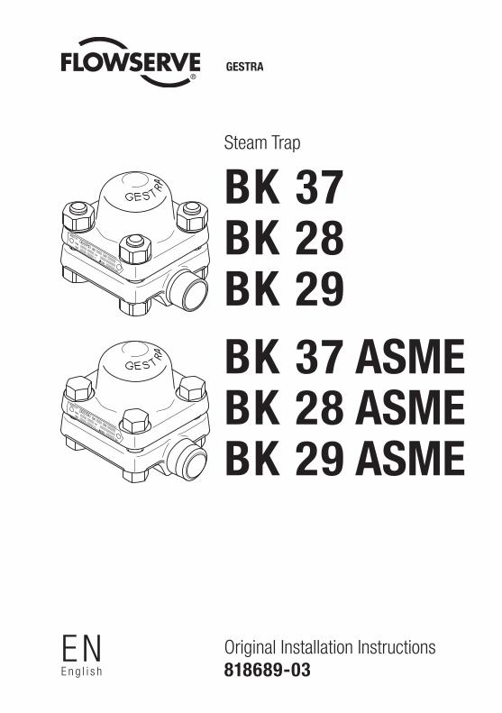
BK 37BK 28BK 29BK 37 ASMEBK 28 ASMEBK 29 ASME
Steam Trap
Original Installation Instructions818689-03
ENE n g l i s h
�
Contents
Important Notes Usage for the intended purpose .................................................................................... 4Safety note .................................................................................................................. 4Danger ........................................................................................................................ 4Attention ..................................................................................................................... 4PED (Pressure Equipment Directive) .............................................................................. 4ATEX (Atmosphère Explosible) ....................................................................................... 4Note on the Declaration of Conformity / Declaration by the Manufacturer ........................ 4
Explanatory NotesScope of supply ........................................................................................................... 5 Description .................................................................................................................. 5
Technical dataName plate / marking ................................................................................................... 5
DesignComponent parts BK 37 6Component parts BK 37 ASME...................................................................................... 7Component parts BK �8, BK �9 .................................................................................... 8Component parts BK �8 ASME, BK �9 ASME ................................................................. 9Key ........................................................................................................................... �0
InstallationAttention ................................................................................................................... ��BK 37, BK 37 ASME, BK �8, BK �8 ASME, BK �9, BK �9 ASME .................................... ��Danger ...................................................................................................................... ��Installation instructions ............................................................................................... ��Attention ................................................................................................................... ��Heat treatment of welds ............................................................................................. ��Tools ......................................................................................................................... ��
Commissioning ProcedureBK 37, BK 37 ASME, BK �8, BK �8 ASME, BK �9, BK �9 ASME .................................... ��Danger ..................................................................................................................... ��
Page
3
Contents – continued –
Operation Attention ................................................................................................................... ��
MaintenanceDanger ...................................................................................................................... �� Checking steam traps ................................................................................................ �3Cleaning / exchanging Thermovit® regulator and strainer ............................................. �3Tools ......................................................................................................................... �3Tightening torques ..................................................................................................... �3
Spare PartsBK 37, BK 37 ASME, BK �8, BK �8 ASME, BK �9, BK �9 ASME .................................... �4Spare parts list .......................................................................................................... �4
DecommissioningDanger ...................................................................................................................... �5Attention ................................................................................................................... �5Disposal .................................................................................................................... �5
Page

4
Important Notes
Usage for the intended purposeUse steam traps BK 37..., BK �8... and BK �9... only for the discharge of condensed water from steam lines or for air venting. Application in steam lines for the discharge of condensate only within the specified pressure and temperature ratings. Check corrosion resistance and chemical suitability for the application in question.
Safety noteThe equipment must only be installed and commissioned by qualified and competent staff.
Retrofitting and maintenance work must only be performed by qualified staff who – through adequate training – have achieved a recognised level of competence.
DangerThe equipment is under pressure and hot during operation. Risk of severe injuries and burns to the whole body.Installation and maintenance work should only be carried out when the system is depressurized (0 bar) and cold (�0 °C).The equipment must be isolated and vented from both upstream and downstream pressure before installation or maintenance work is performed.Sharp edges on internals present the danger of cuts to hands.Always wear industrial gloves when servicing the equipment.
AttentionThe name plate specifies the technical features of the equipment. Do not commission or operate any item of equipment that does not bear its specific name plate. The pressure and temperature ratings on the name plate of the equipment must meet the requirementes of the installation.
PED (Pressure Equipment Directive)The equipment fulfills the requirements of the Pressure Equipment Directive PED 97/�3/EC.For use with fluids of group �.The equipment is excluded from the scope of the PED according to section 3.3 and must not bear a CE marking.
ATEX (Atmosphère Explosible)The equipment does not have ist own potential source of ignition and is therefore not subject to the ATEX Directive 94/9/EC.Applicable in Exzones 0, �, �, �0, ��, �� (�999/9�/EC). The equipment is not Ex marked.
Note on the Declaration of Conformity / Declaration by the Manufacturer For details on the conformity of our equipment according to the European Directives see our Declaration of Conformity or our Declaration of Manufacturer.The current Declaration of Conformity / Declaration of Manufacturer are available in the Internet under www.gestra./de/documents or can be requested from us.
5
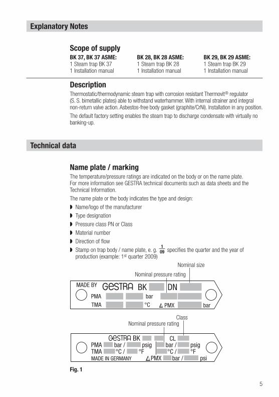
Name plate / markingThe temperature/pressure ratings are indicated on the body or on the name plate. For more information see GESTRA technical documents such as data sheets and the Technical Information.
The name plate or the body indicates the type and design:
Name/logo of the manufacturer
Type designation
Pressure class PN or Class
Material number
Direction of flow
Stamp on trap body / name plate, e. g. specifies the quarter and the year of production (example: �st quarter �009)
Explanatory Notes
Technical data
109
Fig. 1
Nominal size
Nominal pressure rating
ClassNominal pressure rating
Scope of supplyBK 37, BK 37 ASME: BK 28, BK 28 ASME: BK 29, BK 29 ASME: � Steam trap BK 37 � Steam trap BK �8 � Steam trap BK �9� Installation manual � Installation manual � Installation manual
DescriptionThermostatic/thermodynamic steam trap with corrosion resistant Thermovit® regulator (S. S. bimetallic plates) able to withstand waterhammer. With internal strainer and integral nonreturn valve action. Asbestosfree body gasket (graphite/CrNi). Installation in any position.
The default factory setting enables the steam trap to discharge condensate with virtually no bankingup.
6
Fig. 2
Design
1
5
4
3
6
7
9
7
8
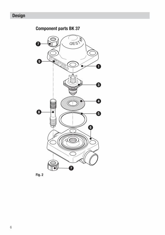
Component parts BK 37
7
Fig. 3
Componen Parts – continued –
1
5
4
3
6
7
9
0
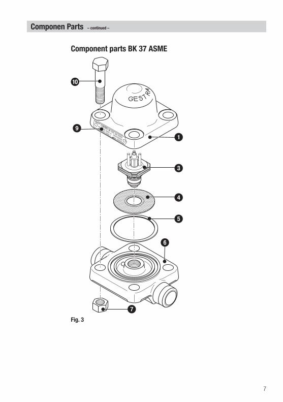
Component parts BK 37 ASME
8
Fig. 4
Componen Parts – continued –
1
5
4
2
6
8
7
9
7
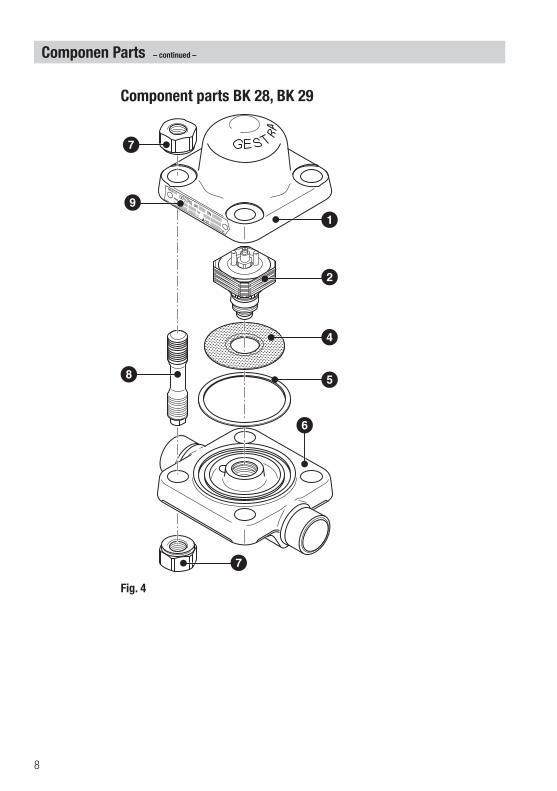
Component parts BK 28, BK 29
9
Fig. 5
Componen Parts – continued –
1
5
4
2
6
7
9
0
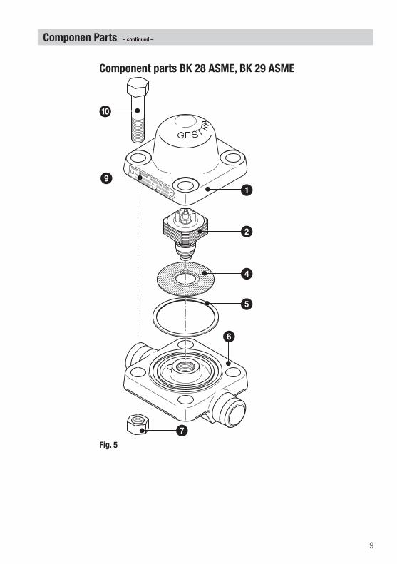
Component parts BK 28 ASME, BK 29 ASME

�0
Componen Parts – continued –
Key
1 Cover
2 Thermovit® regulator BK �8, BK �8 ASME, BK �9, BK �9 ASME
3 Thermovit® regulator BK 37, BK 37 ASME
4 Strainer
5 Gasket
6 Body
7 Hexagon nut
8 Expansion bolt with reduced shank to DIN �5�0
9 Name plate
0 Threaded bolt
��
Installation
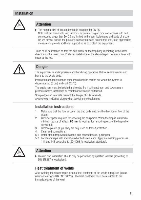
Attention The nominal size of this equipment is designed for DN �5.
Note that the admissible loads (forces, torques) acting on pipe connections with end connections larger than DN �5 are limited to the permissible pipe end loads of a size DN �5 device. Should the pipe end connection loads exceed this limit, take appropriate measures to provide additional support so as to protect the equipment.
Traps must be installed so that the flow arrow on the trap body is pointing in the same direction as the steam flow. Preferred installation of the steam trap in horizontal lines with cover at the top.
DangerThe equipment is under pressure and hot during operation. Risk of severe injuries and burns to the whole body.
Installation and maintenance work should only be carried out when the system is depressurized (0 bar) and cold (�0 °C).
The equipment must be isolated and vented from both upstream and downstream pressure before installation or maintenance work is performed.
Sharp edges on internals present the danger of cuts to hands.Always wear industrial gloves when servicing the equipment.
Installation instructions�. Make sure that the flow arrow on the trap body matches the direction of flow of the
steam.�. Consider space required for servicing the equipment. When the trap is installed a
minimum space of at least 80 mm is required for removing parts of the trap when servicing it.
3. Remove plastic plugs. They are only used as transit protection.4. Clean end connections.5.� Install steam trap with releasable end connections (e. g. flanges).5.� For steam traps with socketweld or buttweld ends: Apply arc welding processes
��� and �4� according to ISO 4063 (or equivalent standard).
Attention Welded trap installation should only be performed by qualified welders (according to
DIN EN �87 or equivalent).
Heat treatment of weldsAfter welding the steam trap in place a heat treatment of the welds is required (stress relief annealing to DIN EN �005�9). The heat treatment must be restricted to the immediate area of the weld.
��
Commissioning Procedure
Operation
Maintenance
Installation – continued –
Tools Combination spanner A. F. �4 mm, DIN 3��3, form B
Make sure that all connections are subjected to a suitable pressure test according to the pertinent rules and regulations.
DangerThe equipment is under pressure and hot during operation. Risk of severe injuries and burns to the whole body.
Installation and maintenance work should only be carried out when the system is depressurized (0 bar) and cold (�0 °C).
The equipment must be isolated and vented from both upstream and downstream pressure before installation or maintenance work is performed.
Sharp edges on internals present the danger of cuts to hands.Always wear industrial gloves when servicing the equipment.
AttentionDrain steam trap if the installation is shut down and ambient temperatures ≤ 0 °C (frost) are to be expected.
Periodic testing and maintenance of the equipment is recommended to ensure proper functioning. Continuous monitoring is recommended for critical applications.
DangerThe equipment is under pressure and hot during operation. Risk of severe injuries and burns to the whole body.
Installation and maintenance work should only be carried out when the system is depressurized (0 bar) and cold (�0 °C).
The equipment must be isolated and vented from both upstream and downstream pressure before installation or maintenance work is performed.
Sharp edges on internals present the danger of cuts to hands.Always wear industrial gloves when servicing the equipment.
�3
OKS ��7® is a registered trademark of OKS Schmierstoffe GmbH, München, Germany
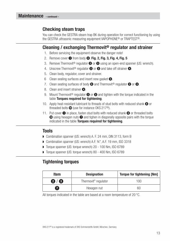
Item Designation Torque for tightening [Nm]
2 / 3 Thermovit® regulator �00
7 Hexagon nut 60
All torques indicated in the table are based at a room temperature of �0 °C.
Maintenance – continued –
Checking steam trapsYou can check the GESTRA steam trap BK during operation for correct functioning by using the GESTRA ultrasonic measuring equipment VAPOPHONE® or TRAPTEST®.
Cleaning / exchanging Thermovit® regulator and strainer �. Before servicing the equipment observe the danger note!
�. Remove cover 1 from body 6. Fig. 2, Fig. 3, Fig. 4, Fig. 5 3. Remove Thermovit® regulator 2 or 3 using an openend spanner (US: wrench).
4. Unscrew Thermovit® regulator 2 or 3 and take off strainer 4.
5. Clean body, regulator, cover and strainer.
6 Clean sealing surfaces and insert new gasket 5.
7. Clean seating surfaces of body 6 and Thermovit® regulator 2 or 3.
8. Clean and insert strainer 4.
9. Mount Thermovit® regulator 2 or 3 and tighten with the torque indicated in the table Torques required for tightening.
�0. Apply heatresistant lubricant to threads of stud bolts with reduced shank 8 or threaded bolts 0 (use for instance OKS ��7®).
��. Put cover 1 in place, fasten stud bolts with reduced shank 8 or threaded bolts 0 using hexagon nuts 7 and tighen in diagonally opposite pairs with the torque indicated in the table Torques required for tightening.
Tools Combination spanner (US: wrench) A. F. �4 mm, DIN 3��3, form B
Combination spanner (US: wrench) A.F. ¾", A.F. �9 mm, ISO 33�8
Torque spanner (US: torque wrench) �0 �00 Nm, ISO 6789
Torque spanner (US: torque wrench) 80 400 Nm, ISO 6789
Tightening torques
�4
Spare Parts
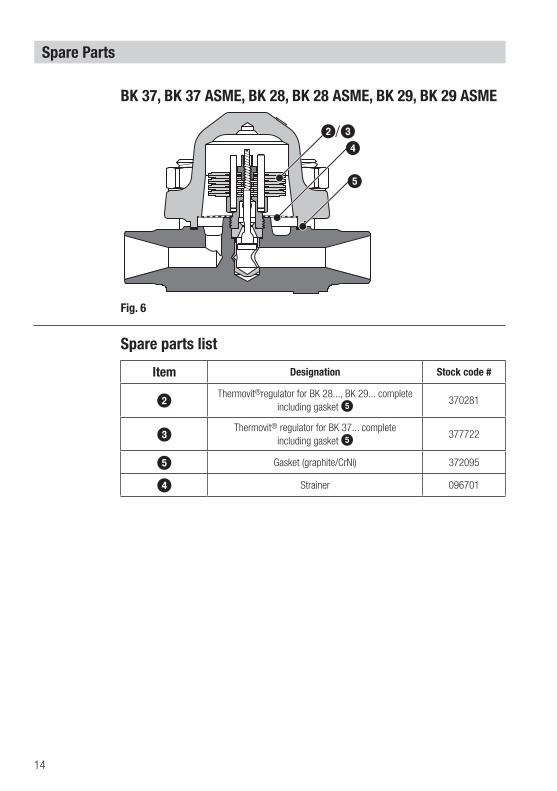
Item Designation Stock code #
2Thermovit®regulator for BK �8..., BK �9... complete
including gasket 5 370�8�
3Thermovit® regulator for BK 37... complete
including gasket 5 3777��
5 Gasket (graphite/CrNi) 37�095
4 Strainer 09670�
2/34
5
Fig. 6
BK 37, BK 37 ASME, BK 28, BK 28 ASME, BK 29, BK 29 ASME
Spare parts list
�5
Decommissioning
DangerThe equipment is under pressure and hot during operation. Risk of severe injuries and burns to the whole body.
Installation and maintenance work should only be carried out when the system is depressurized (0 bar) and cold (�0 °C).
The equipment must be isolated and vented from both upstream and downstream pressure before installation or maintenance work is performed.
Sharp edges on internals present the danger of cuts to hands.Always wear industrial gloves when servicing the equipment.
AttentionDrain steam trap if the installation is shut down and ambient temperatures ≤ 0 °C (frost) are to be expected.
DisposalFor the disposal of the equipment observe the pertinent legal regulations concerning waste disposal.
�68�868903/09�0�0cm (80373805) · GESTRA AG · Bremen · Printed in Germany
GESTRA
Agencies all over the world: www.gestra.de
GESTRA AGP. O. Box�0 54 60, D�8054 Bremen Münchener Str. 77, D�8��5 BremenTelephone 0049 (0) 4�� / 35 03 0 Fax 0049 (0) 4�� / 35 03 393E mail [email protected] Internet www.gestra.de
Branch offices:
Great Britain
Flowserve GB LimitedAbex RoadNewbury, Berkshire RG�4 5EYTel. 0044 �6 35 / 46 99 90Fax 0044 �6 35 / 3 60 34Email: [email protected]
Italia
Flowserve S.r.l.Flow Control DivisionVia Prealpi, 30/3�l�003� Cormano (MI)Tel. 0039 0� / 66 3� 5�Fax 0039 0� / 66 3� 55 60Email: [email protected]
España
Flowserve GESTRA U.S.�34� Ampere DriveLouisville, KY 40�99Tel. 00� 50� / �67��05Fax 00� 50� / �665397Email: [email protected]
USA
Portugal
Flowserve Portuguesa, Lda.Av. Dr. Antunes Guimarães, ��59Porto 4�0008�Tel. 0035� �� / 6 �9 87 70Fax 0035� �� / 6 �0 75 75Email: [email protected]
Polska
GESTRA ESPAÑOLA S.A.Luis Cabrera, 8688E�800� MadridTel. 0034 9� / 5 �5 �0 3�Fax 0034 9� / 4 �3 67 47; 5 �5 �0 36Email: [email protected]
GESTRA POLONIA Spolka z.o.o.Ul. Schuberta �04PL 80�7� GdanskTel. 0048 58 / 3 06 �0 0� 0048 58 / 3 06 �0 �0Fax 0048 58 / 3 06 33 00Email: [email protected]


![Further study of Advanced MIMO receiverpeng/MIMO-Receiver.pdf · b k [b1 b2 bk 1 bk 1 bN],bk [b1 b2 bk 1 1 bk 1 bN] and bk [b1 b2 bk 1 1 bk 1 bN] Problem: the number of combinations](https://static.fdocuments.net/doc/165x107/5fe7675492953575f353f746/further-study-of-advanced-mimo-receiver-pengmimo-b-k-b1-b2-bk-1-bk-1-bnbk.jpg)