Steam Survey - PB Heat: Peerless® Boilers. System Types 1. One-Pipe System – one pipe feeds each...
10
Survey Systems Steam Hydronic Pre-Installation Survey and Checklist for Steam Systems
Transcript of Steam Survey - PB Heat: Peerless® Boilers. System Types 1. One-Pipe System – one pipe feeds each...

SurveySystems
SteamHydronic
Pre-InstallationSurvey andChecklist forSteam Systems

INSTALLATION SURVEY – STEAM
A. Introduction
1. Use this survey to review the system for operatingbehavior and history. The survey should give you sometips on making the installation successful. It might alsogive you some recommendations to pass on to the ownerfor corrections needed in the system to avoid problemslater.
2. DEFINITIONS AND RATINGS:
EDR =
Equivalent Direct Radiation240 Btuh per ft2 SteamNote: Boiler ratings in EDR include anallowance for piping and pickup losses
PPHCondensate = Pounds per Hour of Condensate
EDR ÷ 4
GPMCondensate =
Gallons per Minute½ gpm per 1000 ft2 EDR2 gpm per 1000 PPH Steam2 gpm per Million Btuh
PPHSteam =
Given from & at 212o F970 Btu per Pound SteamIBR Gross Output ÷ 970
B. System Types
1. One-Pipe System – one pipe feeds each radiator,handling both the steam supply and the condensatereturn. This pipe is near the bottom of the radiator.● One-pipe gravity return systems need an air vent
near the middle of each radiator and a main ventnear the end of the steam main and each riser.
● One-pipe pumped return systems have air vents onthe radiators like gravity return systems. But the endsof the steam main and risers need traps instead ofvents. You’ll usually find they have been fitted withfloat and thermostatic traps or thermostatic traps withcooling legs.
● One-pipe Paul systems have a special Paul air ventand an air vacuum pump to quickly remove the air.
2. Two-Pipe System – two pipes serve each radiator—steamsupply and condensate return. The steam supply pipe isnear the top. The condensate return pipe is near thebottom.● Two-pipe pumped return and vapor systems use a
trap on each radiator condensate line to preventsteam from passing through.
● Two-pipe gravity systems have individual pipes fromthe radiator condensate lines to the system wet return.
14"Pressure
Difference
14"Pressure
Difference28"
6"Return Line Loss
6"Return Line Loss
8"Start-up Condensate
8"Start-up Condensate
A
Note: Return line loss includes safety factor
GRAVITYRETURN
Figure 1: Gravity Return – Dimension A
Pitch up1" per 10 ft
Maximum MainLength 100 ft
MainVent
Water Line
Boiler
A
Figure 2: Counterflow System, Typical
Characteristic of a Counterflow Gravity Return System:● Steam main pitched upward, away from boiler
(minimum of one inch per 10 feet)● Steam main one size larger than parallel flow header
for same heating load● No dry or wet return● Condensate flows against steam flow● Boiler steam line enters top of steam main
The steam pressure at the end of the steam main is lower than atthe boiler by about ½ psig (14 inches) on most systems. So thecondensate must be 14 inches higher than the boiler water levelto equalize this difference.Another 6 inches is needed for the friction loss through the returnline. And 8 inches must be allowed for the cold start-upcondensate load.So the lowest steam carrying pipe in the system must be at least28 inches above the boiler water line. This dimension is calledDimension A.
INSTALLATION SURVEY – STEAM
1

3. Gravity Return System – condensate returns to theboiler only due to gravity flow. A gravity return systemworks like a U-tube manometer. The pressure at theboiler is higher than at the end of the steam main. Andthe condensate loses pressure to friction as it flowsthrough the returns. So condensate backs up into thereturn riser(s) until the weight of the water column isenough to balance the pressure difference and push thecondensate into the boiler. See Figure 1.
Examples of One-Pipe Gravity Return Systems:● Counterflow (Figure 2)● Parallel Flow (Figures 3 and 4)● Parallel Flow Upfeed (Figure 5)● Parallel Flow Downfeed (Figure 6)
a) Counterflow, Parallel Flow and Parallel Flow Upfeedsystems all have a steam main near the bottom of thesystem.
b) Parallel Flow Downfeed systems have a steam mainat the top of the system. Steam is delivered to thebranches through downfeed risers.
4. Pumped Return System – condensate is returned tothe boiler with a condensate unit, boiler feed unit orvacuum unit. Pumped return is used on one-pipe andtwo-pipe systems.
5. Vacuum System – a vacuum pump pulls a suction onthe condensate return lines, pulling air and condensatethrough and pulling a vacuum on the system. Vacuumsystems are always two-pipe.
6. Vapor System – a two-pipe gravity return system whichpushes air out and doesn’t let it back in. This causes thesystem to drop to a very low pressure (from 0 to ½ psigusually) as the steam condenses in the radiation.
Pitch down1" per 20 ft
Wet Return
MainVent
Water Line
Hartford LoopBoiler
A
Figure 3: Parallel Flow Gravity, Wet Return
Pitch down1" per 20 ft
Wet Return
Water Line
MainVent
Hartford LoopBoiler
A
Figure 4: Parallel Flow Gravity, Dry Return
Boiler Water Line
Wet Return
HartfordLoop
Riser
RiserDripDirt
AirVent Supply
Valve
MainVent
SupplyMain
A
RiserMainVent
A
A
RiserMainVent
Figure 5: Parallel Flow Upfeed Gravity
Boiler Water Line
Wet Return
DownfeedRisers
SupplyRiser
DirtPocket
AirVentSupply
Valve
RiserMainVent
RiserMainVent
MainVent
SupplyMain
A
HartfordLoop
A
A
Figure 6: Parallel Flow Downfeed Gravity
Characteristics of Parallel Flow Systems:● Steam main pitched downward away from boiler (minimum 1 inch per 20 feet)● Condensate flows with steam, returning through risers to dry or wet return● Steam main taken off top of boiler header between equalizer and last boiler riser
INSTALLATION SURVEY – STEAM
2
C. Gravity Return Systems
1. Figure 1 shows how a gravity system works. The 28 inchdimension for the back-up of water in the returns allowsfor a system steam pressure loss of ½ psig. Make sure toadd additional height allowance if the system pressuredrop is more than ½ psig.
2. The height of the lowest steam carrying pipe (main orbranch) above the boiler water line is called DimensionA. Make sure that Dimension A is always at least 28inches on a gravity return system. If it is less, condensatemay back into the steam main or branches, causing waterhammer, no-heat problems and boiler water levelproblems. Make sure you pipe the new boiler so thisdimension is maintained.
3. When a zone valve or trap is installed between thesteam supply and the condensate return lines, there is nosteam pressure downstream of the valve or trap when itis closed.● So all of the boiler pressure pushes backward on the
return lines. This raises the condensate level about 30inches for every psig pressure at the boiler. That wouldbe 5 feet (60 inches) for only 2 psig at the boiler. Thinkwhat would happen if someone cranked up the steampressure to 5 psig or more.
● In such cases, the height of the lowest steam carryingpipe (main or branch) above the boiler water line iscalled Dimension B. Make sure Dimension B is atleast 30 inches for every psi at the boiler.
● Figure 7 shows Dimension B for a One-Pipe GravitySystem. Figure 10 shows Dimension B for a typicalvapor system.
4. One-pipe systems and two-pipe gravity systemsprovide heat by pushing air out the radiators and steamlines through air vents. The air is pushed out during theheating cycle. After the boiler shuts down, the ventsprevent a vacuum by allowing air to return.
5. The steam main (and each riser) needs a Main Ventinstalled near the end. ( Never install the Main Vent on atee at the end of the steam main. It will be quicklydestroyed by water hammer. See Figure 12. ) Use smallercapacity vents on the radiators. Venting the radiators toofast will cause water hammer in the radiators because thecondensate can’t get out past the rushing steam.
6. The air vents must be working for the building to heatproperly. The Main Vents on the steam main and risersare important for uniform heat in the building. If theydon’t work, the radiator vents have to try to remove theair from the steam lines. This will cause the radiators nearthe boiler to heat much sooner than those further away.So some areas will be hotter than others. See Figure 12for the correct location of the Main Vents.
7. Set the operating pressure for a gravity return systemas low as possible, usually around 2 psig or less at theboiler. The older steam systems were generally designedfor this. And many air vents won’t work correctly atpressures over 2 psig.
D. Pumped Return Systems
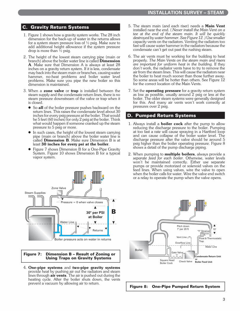
1. Always install a boiler cock after the pump to allowreducing the discharge pressure to the boiler. Pumpingat too fast a rate will cause spraying in a Hartford loopand can cause collapse of the boiler water level. Thedischarge pressure after the valve should be around 5psig higher than the boiler operating pressure. Figure 8shows a detail of the pump discharge piping.
2. When pumping to multiple boilers, always provide aseparate feed for each boiler. Otherwise, water levelswon’t be maintained correctly. Either use separatepumps or provide motorized or solenoid valves on thefeed lines. When using valves, wire the valve to openwhen the boiler calls for water. Wire the valve end switchor a relay to operate the pump when the valve opens.
Boiler pressure acts on water in returns
Water Line
Pressure = 0 when valve closes
30" per PSIat Boiler
Zone Valve
Returns
Steam Supplies
B
Figure 7: Dimension B – Result of Zoning orUsing Traps on Gravity Systems
Pitch down1" per 20 ft
Water Line
Vent Line
Overflow Line
Check Valve
Condensate Return UnitorBoiler Feed Unit
Float & ThermostaticTrap
"Y" Strainer15"
Gate Valve
Square HeadBoiler Cock
Boiler
Figure 8Figure 8:—One-Pipe Pumped Return System
INSTALLATION SURVEY – STEAM
3

3. Condensate Units● Small receiver tank (usually one minute boiler
steaming time) with one or more boiler feed pumpsattached. The standard pump outlet pressure is 20 psig.
● Condensate unit pumps start when the level in thereceiver tank rises. The pump is not operated by theboiler water level controls. This is why you’re alwaysbetteroff installing a boiler feedsystem instead ifpossible.
● Make-up water is usually added at the boiler with afloat-operated feeder control.
● Condensate units are not effective when pumping tomultiple boilers. There is no way of setting which boilerwill receive the water since the condensate unit onlypumps based on the water level in its receiver.
4. Boiler Feed Units● Larger receiver tank, usually sized for at least 15 minutes
boiler steaming time (more if condensate return time islonger), with one or more pumps attached.
● Boiler feed unit pumps start on a call from the boilerwater level controller.
● Make-up water is added at the feed unit receiver.
5. Vacuum Units● A vacuum pump pulls a vacuum on the system
through the condensate, supply and return lines,pulling both air and condensate.
● Air is eliminated through the receiver tank vent.● Vacuum units can be either condensate unit type
(operated by a float in the tank) or boiler feed type(pumping to the boiler on a call from the boiler levelcontrol.)
6. Two-Pipe Pumped Return Systems provide heat bypushing air through the radiator, main and riser traps,allowing steam to enter the radiators. The traps must beworking for the air to be moved out through thecondensate lines to the vent on the condensate or boilerfeed unit. As steam condenses in the radiators, thecondensate drains through the traps. When thecondensate has drained and steam reaches thethermostatic element in the trap, the element expands.This closes the trap seat, preventing steam from enteringthe condensate lines.
7. The main and riser traps must be working for thesystem to heat evenly. If these traps let the air out of thesteam lines quickly, all of the branch lines will receivesteam at the same time. If not, the radiator traps have todo the job, causing radiators near the boiler to heatsooner than those further away. If the traps fail open,steam will pass into the receiver tank, causing highcondensate temperature. This will cause cavitation in thepump impeller, damaging the pump.
8. Traps which fail open on two-pipe systems allow steamto pass into the condensate lines. Steam in the returnscauses hammer and damage to other traps. It alsopressurizes the condensate lines. This eliminates thepressure difference across other traps and prevents themfrom moving air and condensate out of their radiators.The radiators won’t heat.Traps which fail closed allow condensate toaccumulate, resulting in water hammer, no-heatproblems and boiler water level problems (since thecondensate can’t get back).
9. Thermostatic traps are used on radiators. They havea thermal element which expands to close the trap whenexposed to steam temperature. They release condensateat 10o to 30o F below steam temperature. So thermostatictraps also work well for drip lines if piped with at least afive foot cooling leg ahead of the trap.
10. You’ll find Float and Thermostatic Traps on mostdrip lines and heat exchanger drain lines. They containa thermostatic element for rapid movement of air and afloat mechanism for handling condensate. Because theyare float-operated, the condensate can drain at steamtemperature. Float and thermostatic traps are effectiveunder varying or light condensate rates.
11. Water hammer will damage most thermostatic traps andfloat and thermostatic traps, though heavy duty hammerresistant traps are available.
12. Where water hammer is likely, Bucket Traps are oftenused. They have a more rugged construction. Buckettraps are less effective at removal of air and must bemanually primed. They can also lose their prime underlight loads, allowing live steam to pass through.
E. Vapor Systems
1. Characteristics of Vapor System:● System designed to run at very low pressure or vacuum● Usually includes a Boiler Return Trap (or Alternating
Receiver or Differential Loop) and Air EliminatorTrap. See Figure 10.
2. A Vapor System is a special type of two-pipe steamsystem. The Air Eliminator Trap is designed to let the airout. The air check valve on the trap vent prevents the airfrom returning. As steam condenses in the radiators, alow pressure develops in the system.
3. Vapor systems need a special boiler pressure controlcalled a Vaporstat. This control has a very low range,allowing accurate setting of the pressure and preventingsetting the pressure too high for the system.
4. Operating a vapor system at too high a pressure cancause blow through on loop seals and overheating (sincethe radiators were sized for low temperature steam.)
HartfordLoop
Boiler Water Line
Return
Riser
ThermostaticTrap
SupplyValve
SupplyMain
Vent
Figure 9Figure 9:—Two-Pipe Parallel Upfeed System,Figure 9:—Pumped Return
INSTALLATION SURVEY – STEAM
4

5. Vapor system radiators are equipped with special trapson the condensate lines to prevent steam from passingthrough. Some vapor systems also use orificed radiatorsupply valves. The orifice is sized to allow slightly lesssteam through than the radiator can handle. This makessure all the steam condenses so it can’t pass through tothe condensate line.
6. Because the radiators have traps on the condensate lines,the pressure difference between the condensate line andthe boiler is usually too much for gravity return toovercome. The Boiler Return Trap compensates forthis. When the condensate backs up high enough to liftthe boiler return trap float, a valve opens to allow steampressure from the boiler to balance the pressure in thetrap chamber. This allows condensate to flow into theboiler by gravity. When the condensate flows out the floatdrops and the cycle starts again.
7. The Boiler Return Trap is essential to the operation of avapor system. Always replace it with the same thing. Theonly alternative is to repipe the returns, installthermostatic traps on all the radiators, drip traps on thesteam main and risers and install a condensate unit orboiler feed unit.
F. Installation Checklist
❏ Check the System History
● If the system has a history of no-heat problems,check the air vents or traps to make sure they’reworking. Some of them may need to be replaced. TheMain and Riser vents often fail due to water hammerbecause of being piped too close to the ends of mainsor dry returns. See Figure 12.
● If the system has a history of water hammer, checkthe pipe slopes and check for sags in the steam pipingor concentric reducers. Also make sure drip traps areworking. Also check to see if insulation has beenremoved from steam piping and not replaced.
● Find out whether there has been a history of leaks inthe system, particularly in the condensate lines. If theold boiler failed due to oxygen corrosion there is agood chance the system was leaking.
● Use the troubleshooting guide in the completeinstallation manual as an aid to locating problems.This is a chance to let the owner know that justchanging the boiler won’t fix the whole system.
❏ Check the height of the new Boiler Water Levelcompared to the old boiler.
If new boiler water level is Higher:● Parallel flow gravity systems – make sure that the
distance from the new water line to the lowest steamcarrying pipe (Dimension A) will be at least 28 inches.If Dimension A is less than 28 inches, you may needto install a condensate unit or boiler feed unit plus afloat and thermostatic trap at the end of the main andall riser drips. See Figure 8. On some systems, less than28 inches may work, but the risk is that condensatewill back into the main or branches and cause waterhammer or lack of heat.
● If a gravity system is fitted with traps or zone valves,the minimum height difference from the boiler waterline to the lowest steam carrying pipe is 30 inches perpsig at the boiler. Set the boiler operating limit onlyhigh enough for the steam to reach the last radiator.
● Vapor systems – make sure the distance to the BoilerReturn Trap is still high enough for condensate toreturn by gravity. The height from the boiler water levelto the bottom of the trap should be at least 6 inches.
● Pumped return systems – check new water lineagainst overflow line on receiver vent piping. Somevent lines include an overflow tee at the boiler waterlevel.
If new boiler water level is Lower:● Parallel flow gravity systems – check the height of
the lowest dry returns. If any part of a gravity returnwet return line will be above the new boiler water line,mount the boiler on a pedestal if possible to obtain thecorrect height. If this can’t be done, install a false waterline (Figure 11) in order to completely cover thereturn. Otherwise, water hammer will occur in thereturn.
● Vapor systems – water level must be at least as highas the loop seal pipe at the end of the main. Elevatethe boiler base if needed for this loop seal to be belowthe boiler water line. If the loop seal is exposed steamwill pass through to the returns, causing water hammerand no-heat problems.
❏ Check the system Condensate Return TimeLag
● If the old boiler is still operational, time how long ittakes for the condensate return line to begin warmingwhen the boiler is started from a cold system. This isthe Condensate Return Time Lag. If the time lagis over 15 minutes, you will probably need to install aboiler feed unit. The storage receiver on the feed unitwould be sized to be at least the time lag (minutes)
BoilerReturnTrap
AirEliminator
Trap
ABEnd ofSteam
Main
ReturnMain
6"or more
At WaterLine
ThermostaticTrap
Check
Check
Check Air Check
BoilerReturn
Pipe Cap SlightlySet In Concrete
To BoilerSteamHeader
Figure 10:Figure 10:—Typical Vapor System BoilerFigure 0:0—Return Trap and Air EliminatorFigure 0:0—Trap
INSTALLATION SURVEY – STEAM
5

times the boiler steaming rate (GPM) times 1.33 (toallow for the unused storage in the receiver.
● Always use a boiler feed unit when possible.Boiler feed units compensate for large or slowreturning systems by providing the water the boilerneeds until the condensate begins to return.Condensate units and gravity return systems can’t dothis. If the boiler doesn’t have enough water contentto steam until the condensate returns, make-up waterwill be added. This will cause flooding and oxygencorrosion (because of the oxygen carried in by thefresh water).
● If you decide to convert a gravity system to pumpedreturn, make sure you can place traps in all the placesneeded—radiator traps and drip traps on mains andrisers.
● If the old boiler is not operational, make a judgmenton the size of the system and how long it will take forthe condensate to come back. When in doubt,recommend a boiler feed unit to the owner. A boilerfeed unit is always preferred because it responds to theneeds of the boiler.
❏ Check the System Piping
● Check steam lines, runouts and branches forright amount of pitch. Lines need to pitch in thedirection the condensate is supposed to flow. If theydon’t, water hammer and no-heat problems mayoccur. On counterflow systems, the pipes must pitchback toward the boiler. On parallel systems, the linesmust pitch toward the returns.
● Checksteamlines forsags.Sagsallowwater topocket,causing water hammer when the system starts up.
● Make sure there are no concentric reducers in anysteam lines except where the pipe size is increasing.Concentric reduces cause water pocketing and waterhammer when used in the wrong places.
● The steam lines must be insulated. If theinsulation has been removed in the past it should bereplaced. Uninsulated steam lines cause heavycondensate loads due to heat loss from the piping andcan cause hammer on shutdown due to momentaryvacuum in the lines. The extra steam and condensateloads can also cause boiler water level problems andoverfilling of the system.
● Check wet returns for leaks. The wet return linesare usually corroded worse than any other part of thesystem because acidic water constantly lays in thepipes. If the returns are leaking, recommendreplacement of the piping to the owner. If the old wetreturns were buried, you may need to run new dryreturns. Make sure Dimension A will be at least 28inches (to the lowest part of the dry return).
● If you leave leaks as is, make-up water will constantlybe added to the system. This will risk liming andoxygen corrosion of the boiler and result in a shortboiler life.
❏ Check Air Vents and Traps
One-Pipe Systems – Check Main, Riser andRadiator Air Vents● The steam main piping Main Vent is often piped at the
very end of the main on a tee. This can lead to quickfailure of the vent due to water hammer at the end ofthe steam main. Figure 12 shows the correct wayto install the Main Vent to be sure it will last.
● Make sure the riser vents (at tops of risers on upfeedsystems; on lower part of risers on downfeed systems)are working. These should be high capacity vents likethe Main Vent on the steam main piping.
● Check radiator air vents. They must be working forthe radiators to heat correctly.
● Make sure the radiator supply valves on one-pipesystems are fully open. One-pipe radiators cannot beregulated by closing down on the radiator supply valvebecause this will cause water hammer in the radiatorsince condensate has to flow back through the valveagainst the steam flow.
Two-Pipe Systems – Check Main and Riser DripTraps● The steam main and risers are usually provided with
drip traps, most often float and thermostatic traps.Thermostatic traps may also be used, piped with acooling leg at least 5 feet long on the trap inlet.
● The drip traps serve to remove condensate from themain and risers and to allow air to pass on the start ofthe heating cycle and return at the end of the cycle.
● A drip trap on the steam main or return mainneeds to be installed as shown in Figure 13. The pipingahead of the trap provides a column of condensatehigh enough to be sure the trap will drain thecondensate even with no pressure on the steam line.This prevents condensate from backing up in thehorizontal pipe and causing water hammer.
● Riser and main drip traps are important in the quickremoval of air from the steam lines. They assure thatall radiator branches receive steam at the same time.
Main Vent
Water Level
BOILER
Steam Main
4"
"A"at least 28"
FalseWater Line
CloseOpen
AirVent
1½" Pressure Equalizer Line
Equalizer mayhammer oninitial start untilit fills up to falsewater level. Fillwet return usingFill Valve to avoid.
Minimum12"nipple
FillValve
Figure 11Figure 11:—Installing False Water Line toFigure 0:0—Submerge Returns When NewFigure 0:0—Boiler Water Level is Too Low
INSTALLATION SURVEY – STEAM
6

● Vapor systems – check the thermostatic trapbetween the end of the steam main and the returnmain. This trap allows air to flow to the condensatereturn line and out the Air Eliminator trap.
Two-Pipe Systems – Check Radiator Traps
● If any radiator traps have failed open, steam canenter the condensate lines. This will cause a no-heatproblem on radiators higher in the system because thepressure in the condensate lines prevents the othertraps from passing air and condensate.
● If radiator traps need to be replaced, all defectivetraps should be replaced at the same time, andwith the system cold. Otherwise, the new trapscould be damaged by water hammer caused by steampassing into the returns.
● Bear in mind that the radiators that aren’t heating maynot have defective traps. Their traps may just beprevented from working because traps lower in thesystem are allowing steam to enter the condensatelines. When a trap fails open, its radiator usually heats,but other radiators above it don’t.
● Thermostatic traps can be tested by checking thetemperature of the condensate line after the trap. Theoutlet temperature of a thermostatic trap should be atleast 10o F cooler than the steam. If the outlet of thetrap is too hot, either the trap tested is bad or one nearit is bad. This temperature method can be done withthermal markers (such as Tempilstiks). This methodmay work in most cases, but the best way to test thetrap elements is in a separate testing station. Thestations can be piped off the steam line in boiler room.
❏ Check the Pump Unit (Condensate, Boiler Feedor Vacuum)
● Make sure the pump is working and that thepump seals are in good condition. Leakage at theseals will cause make-up water to be added to the system.
● Defective traps can result in damage to any pump.Steam in the condensate lines causes hightemperature condensate, which flashes in the pumpimpeller, causing cavitation. This will quickly erode theimpeller blades and destroy the pump.
● Check the return line leading to the receiver. It mustbe sloped downward to the receiver with no sags orrises. Anything which will allow water to sit in the lineswill prevent air from being pushed into the receiverand out the receiver vent line. This can also causewater hammer in the return.
● Check that the vent line is installed and open to theatmosphere on condensate units, boiler feed units andvacuum units. Their receivers are not designed to bepressurized.
❏ Plan the Near-Boiler Piping and its connectionto the steam main
● The boiler steam header must be at least 24 inchesabove the normal boiler water line (center of the gaugeglass).
● On boilers with multiple risers, the system steamtake-off(s) should be between the last boilerriser and the equalizer line. When the piping isinstalled correctly, as shown in Figure 14, water isseparated from the steam as the steam turns up intothe take-offs. The figure also shows how water poolsunder the take-off if it is between the boiler risers,causing water carryover to the system.
● Use the number of risers off the boiler in the locationsshown in the manual. Reducing the number ofrisers or incorrectly placing them will causethe water level to be sloped inside the boiler.This can cause overheating of the sections and resultin cracks.
Main Vent
Main Vent6 to 10"
15"minimum
RIGHT WRONGVent will be damaged bywater hammer at end ofmain or return
Vent protected from waterhammer
Steam Mainor Dry Return
Steam Mainor Dry Return
Figure 12
Static Head
Figure 13
Figure 12:—Correct Piping of Main Vent toFigure 9: —Prevent Water Hammer Damage
Figure 13:—Piping a Drip Trap on the End ofFigure 9: —a Steam Main
INSTALLATION SURVEY – STEAM
7

● The boiler header must be offset to provideswing joints. The swing joints prevent the expansionand contraction of the header from damaging theboiler.
● Size the boiler equalizer line as recommended in theseinstructions. This assures the most stable water levelpossible and prevents water from spraying up into theheader.
● We recommend the use of a Hartford loop even onpumped return as an added precaution against waterleaking back through the check valve into the receivertank. The equalizer sizes recommended should beadequate for pumped return, provided the pump rateis not excessive.
● The near-boiler piping must be done as shownin these instructions. This piping is designed toassure dry steam is provided to the system. Undersizedpipes and steam take-offs in the wrong locations cancause large amounts of water to be carried into thesystem (Figure 14). The result would be water hammerand damage to system traps and vents. It will alsocause make-up water to be added to the system dueto frequent low water conditions in the boiler.
● Vapor systems – the two check valves below theBoiler Return Trap are essential to the system. Theymust be piped as required for the system and must beworking correctly. Maintain the correct positions of theBoiler Return Trap and Air Eliminator Trap relative tothe boiler water line.
Wate
Wate
HEADER CONNECTIONSFOR MULTIPLE BOILER RISERS
EQ
UA
LIZ
ER
EQ
UA
LIZ
ER
Water separates when thesteam turns upward
Water pools under the steamtake-off, causing heavy carryoverof water to the system
Figure 14: One-Pipe Pumped Return SystemFigure 14:—LLocation of Steam Take-Off on Multiple Riser Boiler
INSTALLATION SURVEY – STEAM
8

SurveySystems
SteamHydronic
Pre-InstallationSurvey andChecklist forSteam Systems
6785 R2 (11/10-2M)Printed in U.S.A.
©2010
PB HEAT, LLC131 S. CHURCH STREET • BALLY, PA 19503