Steam Locomotive Repair and Overhaul Module LM2 · Steam Locomotive Repair and Overhaul Module ......
24
Steam Locomotive Repair and Overhaul Module LM2 Axleboxes and Journal Bearings Richard Gibbon & Tony Simons July 2016 – version 1
Transcript of Steam Locomotive Repair and Overhaul Module LM2 · Steam Locomotive Repair and Overhaul Module ......

Steam Locomotive Repair and Overhaul Module LM2 Axleboxes and Journal Bearings Richard Gibbon & Tony Simons July 2016 – version 1

Module BESTT LM2
Axleboxes and Journal Bearings
Aim
This unit will give learners and understanding of how axleboxes and bearings are constructed and function in relation to Steam locomotives and how to inspect and suggest methods of repair. Attention will also be given to the importance of lubrication.
INTRODUCTION
What axleboxes do?
Where are they located?
Alien lubrication philosophy
The entire load on all the time
Drip trays at the NRM
Worsted wool trimmings
Preparing locomotives for the big move
Peculiar and special conditions for loco axleboxes
The use of rapeseed oil.
Tacit knowledge loss with demise of steam
Withstanding piston thrust forces
The bearings that support the wheels and axles of a steam locomotive and transmit the propelling and braking forces to the rails are key to the success and reliability of the completed machine.
Because the bearings and axleboxes are generally located in an inaccessible part of the steam locomotive, it is easy to assume in any rebuild or repair that the axleboxes are in the right place and alignment and need no attention.
Also because the method and materials involved in the lubrication is completely alien to the “Fit and forget” bearing technology of modern machines it is very easy to get this matter wrong. The results of axlebox failure on the main line or Heritage Railway can be damaging and expensive.
The situation whereby the whole weight of the locomotive during often long out of use periods sits stationary in metal to metal contact, creates a scenario which is unlike that found in other modern machines and needs special knowledge, understanding and materials to function correctly. In some ways the situation is worse in the preserved sector than it was when locomotives were in daily use, as the oil can be squeezed out of the radial gap within the bearing and increase the risk of lubrication failure.

Two personal anecdotes might illustrate this point.
Firstly when I first came as Chief Engineer to the NRM there were neat tinsmith-made oil trays located under every journal of every steam locomotive on display with slight amounts of oil content in every tray. It gave the impression of great attention to detail and wanting to keep the display area tidy and ship-shape, with no oil drips being allowed on the museum floor. Nothing could have been further from the truth! The humidity variations taking place with large numbers of visiting public were allowing condensation of the moisture in the air to take place on the cold metal within the axleboxes. The slowly increasing liquid content in each oil reservoir at the base of each axlebox within which the worsted wool lubrication wicks dangled very gradually expelled the oil a few drops each day and replaced it with water over the years. Of course the oil was floating on the water and cursory inspection suggested all was well. The water went stagnant over time. The worsted wool tails rotted and dropped off the axle lubricators leaving the bearing seriously at risk, even though it gave the impression of a careful maintenance regime being in place!
Secondly when the whole of the National Collection in the Great Hall of the NRM had to be moved from York to suitable storage at Swindon and other places when the new roof was being erected in 1993, the majority of the collection was chosen to move by rail in secret moves overnight. The very first act was to remove the locomotive from display and drag it with a shunting locomotive the few hundred yards into the Workshops for stripping and examination to see which vehicles were judged fit to travel at restricted speed on the Network, and which would have to go by road on low loaders.
As the first few candidates were stripped in the workshop over the wheel-drop it was clear that the 200-yard journey to the workshop from display had done more harm to the bearing surfaces than a lifetime of running had done! Immediately a rule was introduced to jack up the locomotive in the Great Hall before it was moved so as to allow a fresh charge of lubricating oil to be introduced between the axles and the journals sufficient to lubricate the surfaces for the short journey.
For the team and me this was the best possible introduction to the peculiar and special way that steam locomotive axleboxes work.
In addition to the issues raised above there is the question of suitable lubricants to use in a metal-to-metal axle box. The railway had historically used animal and vegetable fats for over half a century with varying degrees of success but mineral oil brought new sophistication to the bearings. It was discovered that the addition of a proportion of Rape Seed Oil to the mineral oil made a startling difference to the way the bearing behaved. William Stanier (Later Sir William,) gave a paper to the Institute of Locomotive Engineers in 1935 in which he stated that “any Chief Engineer of a Railway who ran his steam locomotive axleboxes without at least 5%, (preferably 10%) Rape Seed Oil was a fool!” (Or words to that effect). This issue and the reasons why this is so will be covered in detail in the module guidance notes. With the demise of steam the leading oil companies nowadays no longer needed to supply these special oils and the whole process became forgotten and had to be relearned by those who presently operate steam locomotives. It was a classic example of “tacit knowledge” becoming lost, which had been passed round but never formalised in guidance materials.

The unusual forces further complicate Axleboxes that the driving axleboxes of a steam locomotive are expected to endure. The reciprocating piston forces can easily exert a lateral force of ten tons on the bearings when an engine is working hard and this must be resisted within the bearing and transmitted via the Hornblock to the frame of the locomotive. This can be tricky as the working part of the bearing to carry the weight of the locomotive is only in contact with the axle over the topmost 40 degrees of the whole bearing surface.
Special bronze thrust faces are introduced around the horizontal centre line, which will cope with these largely horizontal forces and not disturb the way the bearing sits on top of the axle during running.
Newcomers are often surprised by the fact that the bearing which they expect to see as a circular hole within the axlebox. Is in fact a small arc of white metal or bronze only in contact with a small section of the axle’s surface.
Richard Gibbon
Learning Outcomes
LO1 Construction, design and general arrangement of different types of axleboxes
LO2 Lubrication of axleboxes, its purpose and methods of applying lubrication.
LO3 Suitable materials for axles, axleboxes and journals. Concept of “friction pairs”
LO4 Secrets of trouble free life with mineral oil lubricated axleboxes.
LO5 “Hot boxes” What, why and how?
LO6 Alignment of axleboxes within the loco frame and its paramount importance.
LO7 Machining axleboxes and journals and fitting for a trouble free life.
LO8 Accommodating vertical movement of the axle. How and why?
LO9 Hornblock types, purpose and how they work incl. wedges and datum points
LO10 Thrust faces on axleboxes. Purpose, machining and fitting.
LO11 Spring adjustment to equalise load on axleboxes.
LO12 Roller bearing axleboxes with cannon-box design. How and why?

Learning Outcomes
LO1:
Construction, design and general arrangement of different types of axleboxes
1. The shape of an axlebox and why it is so. 2. How oil lubrication works in a friction bearing. 3. Withstanding piston thrust within the box. 4. Coping with transverse forces as well as dead weight and rotation. 5. All companies had different ideas and designs.
An axlebox is generally in the form of an inverted horseshoe of cast iron, cast steel or bronze containing bearing metal in the area in contact with the axle. The axlebox sits on the top of the axle and carries a proportion of the weight of the locomotive. There is no part of the bearing in the lower half of the axlebox, as it is never required to carry load.
Lubrication is usually applied to the underside of the rotating journal or shaft so that the bearing supports the load without metal-to-metal contact and as the shaft turns it brings fresh oil into the gap between shaft and bearing. This gap can be up to a thousandth of an inch thick and separates the two metal surfaces as long as rotation is present. The lubrication which is mineral oil is distributed onto the shaft by means of an oiling pad which has worsted wool tails which wick the lubricant up to the surface of the pad from the oil bath or “tray” below the pad which is within the “under-keep” or lower half of the bearing within the jaws of the “U” shape. The pads are spring loaded so as to never lose contact with the axle.
In the case of driving axleboxes the near horizontal propulsion forces being exerted by the pistons, which are pushing and pulling on the axle bring another job that the axlebox has to do.
That back and forth force which can be up to ten tons must be resisted and passed safely through to the frame of the locomotive to create movement of the train. Although the crown of the bearings will be able to withstand moderate fore and aft forces it is generally usual to have horizontal thrust faces, which at the horizontal centreline of the bearing specifically to control the effect of the pistons and handle the forces involved.
The outer faces of each axleboxes also act as a thrust face transmitting cornering forces from the wheels to the frames as the locomotive negotiates curves in the track and is subject to sideways forces correcting the path of the locomotive. Each wheels has a thrust face behind the centre and this in turn bears on the outer face of each axlebox which is generally faced with a suitable bearing material
Each railway. Company designed its own axleboxes and so there many variations in design and execution but the principles described above are universal.

LO Objectives AssessmentCriteria Delivery
Dateachievedand
Supervisorssignature
LO1 1 Axlebox shapes Draw a section through
a typical axlebox Classroom
LO1 2 Lubrication
Draw a diagram to show how oil is distributed to the shaft
Classroom
LO1 3
Understanding how Piston Thrust affects the box
How is the thrust from the piston handled within the axlebox?
Classroom & workshop
LO1 4 Transverse Forces
How does the axlebox handle transverse forces when the locomotive negotiates a curve? Use an annotated diagram
Classroom
LO1 5 Axlebox types
Draw diagrams of an LMS, GWR and L&NWR axlebox
Classroom

LO2:
Lubrication of axleboxes, its purpose and methods of applying lubrication.
1. The purpose of rapeseed additive. 2. Getting the oil; to the gap. Not at the top! 3. The hydrodynamic wedge 4. Wicking and its importance 4. What the top reservoirs are for. 5. Water ingress, how and the consequences 6. Removing under-keeps during preparation. 6. Checking for trapped water. 7. Syringing trapped water. 8. The role and construction of the Armstrong Oiler 9. Vertical movement in axleboxes.
10. Wear in axleboxes as they hammer to and fro. 11. LNER Wedges to control longitudinal play.
The first thing that needs to be understood is that oil as we know it nowadays for automotive and agricultural purposes simply will not do the job! As has already been stated the need to incorporate rape oil compounded into the basic oil mixture is essential because of the way that the journals and bearings can often stand for long periods with no rotation and can squeeze out any remaining oil and bring about metal-to-metal contact. The rapeseed oil will however resist being squeezed out and remains as a sticky tacky product in the tiny gap, which ensures minute permanent separation of the mating parts.
The oil can be applied to the axleboxes through a mechanical lubricator, i.e. forced in under pressure generally at the horizontal centreline of the bearing, or the axlebox can take its lubrication exclusively from the woollen pad fed from the tray in the under-keep. The significance of bringing fresh oil in on the horizontal centreline is that it lubricates exactly where the force from the pistons is being felt.
What must never happen is to have the oil fed in at the top of the crown of the bearing. This can be disastrous as the way the oil lubricated bearing functions is to have a hydrodynamic wedge of oil built up to support the two surfaces apart with the pressure at the crown of the bearing easily achieving 400 lbs./sq. inch under the right conditions. Any attempt to feed oil through the crown, which might seem the obvious place will end in tears as the hydrodynamic wedge feeds its pressure back up the hole and collapses.
Those of you who have studied axleboxes will be protesting that they have seen axleboxes with four pockets for oil reservoirs cast into the top with wicks in them all ready to feed oil to the crown. Not so! Those wicks feed to ahead of or behind the crown so that the rotating axle draws the oil into the gap between the bearing proper and the axle itself. The wicks feed to keep the oil film intact should the pad fail to supply oil to the bottom of the journal.
The difficulty of failed lubrication due to water ingress into the axlebox has already been mentioned and its effect cannot be too highly stressed.

Because the boiler of a steam locomotive is circular, rain runs round the boiler and tends to drip off just above the axleboxes. Of course the water enters the axle box and immediately sinks to the bottom of the oil reservoir becoming invisible. Some axleboxes have drain plugs at the bottom of the under-keep. If these are present then a quick sample lets you know whether water is present.
The best way to check for axle-box water contamination is when preparing the loco for duty is to undo the fastenings and to slide the under-keeps towards the centreline of the locomotive and with a metal syringe to suck a syringe full from the bottom of the underkeep. Then withdrawing the syringe and using firm hand pressure empty the syringe over some waste ground or into some ash. Watch carefully as the liquid leaves the nozzle. Pure oil comes out in a continuous stream. Any water in there splutters and spits as it leaves the nozzle. If water is present it must all be removed with the syringe before refilling and re-assembly.
Several manufacturers make oil suitable for steam locomotive axleboxes. Morris’s of Shrewsbury make two different rape content Compounded Bearing oil as well as several types of Steam Cylinder oil both un-superheated and superheated versions (Usual disclaimer!)
Lubrication Pads are available from Armstrong Oilers c/o North Yorkshire Moors Railway at Grosmont. North Yorkshire. (Usual disclaimer)
New pads must be primed by soaking in the correct oil at least 24 hours before use.
Page 95 to 100 of Locomotive Management Book applies.
Discussion above has centred on the lubrication of the rotating axle in its bearing. However the ability of the axle-box to travel a small amount up and down within the hornblocks is also very important. Usually small holes from the wells on top of the axlebox which contain oil allow a small amount of lubricating oil to the vertical horn block surfaces which guide the axle box up and down under the control of the spring allowing the locomotive wheelset to negotiate undulations in the track.
Much has been made of the piston forces hammering the axlebox back and forward within the frames. This led to wear and excessive clearances developing in worn locomotives which meant that complete axlebox replacement would have been necessary at overhaul. The LNER sought to provide a remedy for this by having a sliding adjustable wedge on the rear face of every coupled axlebox. This meant that the axlebox clearance could be corrected as wear occurred giving the axlebox a longer life during overhauls.
Of course this had an interesting effect on the piston longitudinal clearances within the cylinder. As the wedges were used to take up the clearances, the whole assembly of coupled wheelsets gradually moved forwards so lessening the clearance between the piston and the front cylinder cover. This had to be monitored carefully.

LO Objectives AssessmentCriteria Delivery
Dateachievedand
Supervisorssignature
LO2 1 Use of Rape seed oil
Explain why Rape Seed Oil is used as an additive to the lubricant
Classroom
LO2 2 How oil is applied
Draw a diagram to show how oil is distributed to the journal.
Classroom
LO2 3 Hydrodynamic Wedge
Explain with diagrams how a hydrodynamic wedge forms
Classroom
LO2 4
Top Reservoirs and Wicking
Draw a section through an axle box showing where the wicks feed oil from the top reservoirs
Classroom
LO2 5 Water ingress
Explain how water can enter an axle box and what are the consequences of that happening
Classroom
LO2 6
Checking for water in the underkeeps
How do you remove the underkeeps and check for water. Remove an underkeep.
Classroom & Workshops
LO2 7
Syringing trapped water
Explain how to check for water by syringing and carry out the operation
Classroom & Workshops
LO2 8 Armstrong Oiler
Draw an annotated diagram of a typical Armstrong Oiler Pad. How do you prime a pad?
Classroom
LO2 9 Vertical movement
How is the vertical movement of the axlebox lubricated?
Classroom
LO2 10
Wear & LNER Wedges
Explain the method in which LNER sought to provide adjustment of clearances and the knock on effect on the piston clearances.
Classroom

LO3:
Suitable materials for axles, axleboxes and journals. Concept of “friction pairs”
1. What is “tribology” 2. Matched and miss-matched materials for bearings. 3. The evolution of best friction materials for bearings. 4. White metal and its well-suited role. 5. White metal cannot cope with hammer. 6. Manganese steel liners for vertical sliding faces
The topic is called tribology, that is the study of one metal sliding or rubbing on another, but the upshot for locomotive engineers is that certain materials are ideally suited to the conditions found in a steam locomotive. Others are unsuitable and should be avoided if possible.
Generally like with like is a poor match and does not work well. A steel axle running in a steel axlebox is going to pick up and tear even with lubrication so we must avoid identical materials running together. Generally axles are steel so we would choose a bronze (not brass) to pair with it. Even that can go wrong if the lubrication is not perfect and the best pairing is to have bronze for the axlebox proper lined with white metal to mate with the axle. (Remember it also has to rub up and down vertically within the iron or steel hornblocks attached to the frame).
The combination of materials that was generally agreed to be the best selection was a cast steel or cast bronze axle-box body and under-keep into which was pressed a semi-circular renewable bronze crown. The crown had a serrated inner surface into which was cast a white metal running surface which was accurately machined to suit the journal diameter. We will be defining in later sections the shape of the machined surface within the axlebox but suffice to say that the correct machining of the mating surface between axle and axlebox is of paramount importance to achieve trouble free life. White metal which is an alloy of tin and known in the USA as Babbitt is soft and conformable but with the correct lubrication preventing metal to metal contact, the white metal surface running on a steel axle journal provides a very satisfactory and long lasting friction pairing. (Kenneth Cook’s Swindon Steam describes this process and attempts to improve it in great detail and is definitely recommended further reading for those interested and wanting to learn). Unfortunately white metal is not good at resisting intermittent reciprocating forces such as those encountered on the horizontal centre line so bronze strips were provided within the casting of the bronze crown, at the limits of the white metal surfaces to resist these high horizontal forces.
In recent years the wear of horn faces over time has led to the development of manganese steel horn faces where hard steel plates are welded in to the faces and run hard against hard metal surfaces. The clearances are critical for these assemblies and the lubrication of the sliding surfaces less critical. Manganese steel liners are often found in conjunction with rolling contact bearings where the periodic maintenance is expected to be minimal.
Although the combination of materials known as “friction pairs” that were used to obtain satisfactory results with trouble free running and long life between overhauls sounds to be

over complex, the science of axleboxes has been built up over many years and needs to be fully understood. No wonder engineers were keen to move towards sealed rolling contact bearings rather than oil lubricated friction bearing, but attempting to bring the precision of a Timken Taper roller bearing into the hostile and flexible environment pertaining between a steam locomotive’s frames brings its own challenges as we shall read in a later section!
LO Objectives AssessmentCriteria Delivery
Dateachievedand
Supervisorssignature
LO3 1 Tribology
Explain what you understand by the term ‘Tribology’
Classroom
LO3 2
Matched and Miss-matched materials
Why are two differing materials used for shafts and bearing surfaces?
Classroom
LO3 3 Best friction materials
What are the now recognised materials best suited for a locomotive axlebox?
Classroom
LO3 4 White metal
What is ‘White Metal’ and how is it suited to the role in an axlebox
Classroom
LO3 5
White metal cannot cope with ‘hammer’
How does the design of an axlebox enable white metal to be used and not subject to the ‘hammer’ forces?
Classroom
LO3 6
Manganese Steel Liners
Where are Manganese steel liners used and why were they introduced. Draw a diagram.
Classroom

LO4:
Secrets of trouble free life with mineral oil lubricated axleboxes.
1. Correct alignment between cylinders axles and frames 2. Correct machining and fitting. 3. Correct preparation, correct oil, and running in. 4. Excluding water. 5. Avoiding overloading individual boxes
There are no real actual secrets to trouble free life with locomotive axleboxes but there are certainly some disciplines, which must be followed rigorously to get a trouble free life. Assuming the bearing has been correctly aligned, machined and “run in” properly with no history of running hot in its present configuration, then the important disciplines are involved in the preparation of the bearings before use. The issues of alignment and machining are covered in separate sections of this module.
This involves making sure that there is no water in the oil reservoir, that the tails and contact surfaces of the lubrication pad are in good condition and using the correct grade and type of oil. (Morris’s compounded Bearing Oil is a good starting point …Usual disclaimer). The preparation of the locomotive should involve removing and checking the under -keeps and lubrication pads to make sure that all is well.
Once that oil film is established and the white metal surface is well bedded to the journal then the user should expect many thousands of miles of trouble free life. However something as simple as replacing a broken spring can lead to axlebox difficulties unless you can be sure that the new spring is transferring exactly the same load from the axlebox to the frame as the spring it is replacing.
LO Objectives AssessmentCriteria Delivery
Dateachievedand
Supervisorssignature
LO4 1 Correct Alignment See frame erection
module Classroom
LO4 2 Machining and fitting
Examine an axlebox bearing and check its condition
Workshop
LO4 3
Correct oil and preparation
Check an oiler pad and ensure it is fit for use and detail the oil that is being used
Workshop
LO4 4 Water ingress
Make sure there is no water present, see LO2-6
Workshop
LO4 5
Overloading of individual boxes
See weighing of locomotives LO11 Classroom

LO5:
“Hot boxes” What, why and how?
1. What a hot box is. 2. The effect of running too hot. 3. Getting home after a hot box.
A hot box is the name given to a bearing that is in the process of failing through lubrication breaking down. Hot boxes were more common with traditional oil lubricated journal bearings than with the modern rolling contact bearings, but even so the effect on the running of the train can be catastrophic and can lead to serious damage to the locomotive or piece of rolling stock and delays. We have already covered the concept of Friction Pairs already but if the oil film is to fail for whatever reason then metal to metal contact occurs as hydrodynamic lubrication breaks down, and overheating of the bearing takes place.
The effect of this overheating if left unchecked is to cause the journal of the axle to be damaged and for the carefully shaped white metal phosphor bronze running surface of the bearing to be smeared, melted and torn as local welding of the running surfaces takes place. The White metal bearing surface is based on a tin based metal alloy and it has a low melting point. In a friction paired axlebox the white metal starts to melt and runs out into the underkeep as the bearing overheats and the dead weight starts to sit down on the bronze crown of the axlebox rather than the white metal lining the bronze crown. Bronze against steel is reasonably good as a friction pair and often the locomotive can limp home. Stopping and waiting for the bearing to cool once this damage has occurred is not necessarily a viable option because the local heating often destroys the lubrication paths and channels that are provided to keep the oil film replenished. In some cases the repair gangs developed emergency skates, which could be placed under wheelsets to get the locomotive mobile again without further rotation and damage.
LO Objectives AssessmentCriteria Delivery
Dateachievedand
Supervisorssignature
LO5 1 Hot Box
Describe what you understand by the term ‘Hot Box’
Classroom
LO5 2 Effect of running Hot
What happens when a white metal bearing overheats?
Classroom
LO5 3 Limping home
Is it possible to continue running a loco after a hot box? What procedures would you follow?
Classroom

LO6:
Alignment of axleboxes within the loco frame and its paramount importance.
1. Why alignment is everything. 2. Surely it won’t change during the lifetime of running. 3. Role of Zeiss equipment 4. Getting perfect straight lines and right angles. 5. Losing datum points
The alignment and accuracy with which axleboxes are manufactured and repaired is vital to the proper and smooth running of the machine.
It might be thought that there was no need to worry about alignment of cylinders and axleboxes within the frames once the locomotive left the factory when new. However the environment within which a steam locomotive operates is often rough and harsh. It is very possible during shunting to get a severe blow to one corner of the locomotive frame, which distorts the geometry of the layout permanently.
The Great Western Railway treated alignment of their locomotives frames axles and cylinders as of top importance and they pioneered methods of creating perfection in squareness when locomotives went through Swindon Works. The excellent book Great Western Steam by Kenneth Cook is required reading for all those thinking of getting involved in rebuilding steam locomotives.
During George Jackson Churchward’s regime in the early twentieth century, the GWR worked with the Optical Instrument Makers Carl Zeiss to obtain and use precision equipment that enabled high degree of accuracy and squareness to be achieved at overhaul with all their locomotives. Huge vertical face grinding machines that operated exactly at right angles to the centrelines of the cylinders and could pass right across the frames of the locomotive being erected, caused the old ways of facing hornblocks by hand scraping and filing to be obsolete.
Nowadays Laser setting out gear for building work can set out right angles and straight lines accurately and achieve the same results although it must be realised that measurement is not the complete story! It is measurement followed by the ability to remove metal in the right places that is essential!
The remaining companies within the Big Four and other pre-grouping companies used more basic methods such as tight piano wires stretched through the cylinder bores and trammels to try and achieve the same effect but none came close to the GWR.
It is often quoted (perhaps unfairly), that prior to Nationalisation of the Railways in 1947 that the manufacturing limits for axleboxes and frames entering service with the LNER and LMS were the same figures as the scrapping limits for the GWR!
Certainly Kenneth Cook’s transfer to Doncaster as CME saw the shopping mileages for LNER locomotives rise dramatically.
One other key message needs to be driven home.

All GWR locomotive axleboxes were set up and machined with the axle in the fore and aft centre of the axlebox. The LMS had Datum Points which were centre popped marks riveted into the frames at construction and the axle centre was supposed to be midway between these datum points, but at each repair these datum points could get modified and lost as horns were modified or the frame distorted. The LNER with their Wedge axleboxes to take up the fore and aft slack meant that as the engine became more worn, all three driving axles slowly moved forward towards the cylinders throughout each repair of the locomotive. An admirable idea to save having to keep replacing expensive axleboxes with wider ones as the hornblocks wore but it was a nightmare for holding centrelines to the correct figures!
LO Objectives AssessmentCriteria Delivery
Dateachievedand
Supervisorssignature
LO6 1 Alignment
How could misalignment contribute to excessive wear on axle boxes?
Classroom
LO6 2
How alignment can change
What could cause alignment to change during the running life of a loco?
Classroom
LO6 3
Zeiss equipment and GWR
GWR used Zeiss equipment What is Zeiss equipment and what did it enable?
Classroom
LO6 4
Straight lines and right angles
What methods were used to measure frame alignment and what is used today?
Classroom
LO6 5 Datum Points
What did LMS use for datum points? What is the consequence of loosing those points?
Classroom

LO7
Machining axleboxes and journals, and fitting for a trouble free life.
1. Scraping after machining to achieve the perfect fit. 2. Only “ten to - to ten past”! 3. Collet “wedge” finally eliminates hand scraping. 4. Machining the Collet wedge using a vertical borer.
White metal lined axle boxes used to be scraped once the white metal bearing surface had been machined to the nominal journal size using an engineer’s scraper and engineer’s “Blue” to get the desired bedding fit. The objective was to get good contact in the area from “ten to to ten past the hour” within the bearing crown. Then the scraper was used to ease the entry and exit points for the lubricant on the axle journal to get a perfect bedded shape onto the axle with a nice run in section at each end of the mating surfaces.
This was a very skilful job and of course there was pressure to deskill the job so that it could be done by machine. Thus was born the “Collet Wedge” and I cannot do justice to a description of what it achieves when Kenneth Cook’s book describes so eloquently how the machining replaced the hand scraping and cleverly created the two lead ins described above.
When William Stanier moved from Swindon to the LMS he brought that technology with him and improved it with the Stonier Duchess axlebox. This design stands as an exemplar of how the best sort of oil lubricated friction bearing should be made and maintained.
The really clever bit is that all the hand-scraping is eliminated and by boring the axlebox first at axle journal at exactly journal size, then the box is moved away from centre by 0.020 inch and the cut is radially advanced by 0.010 the two perfect wedge shaped lead-ins for the lubricant are produced reliably, perfectly and accurately without hand scraping..
LO Objectives AssessmentCriteria Delivery
Dateachievedand
Supervisorssignature
LO7 1 Bearing Scraping
Describe how a bearing is hand scraped. Hand scrape a used bearing to understand the process
Classroom & Workshop
LO7 2 Ten to - to - Ten past
Why is only the area referred to as ten to to ten past scraped?
Classroom
LO7 3 Collet ‘wedge’ What is the GWR Collet
wedge system? Classroom
LO7 4
Machining the collet wedge on a vertical borer
How can you machine ‘Collet Wedge’ using a vertical borer?
Classroom

LO8:
Accommodating vertical movement of the axle. How and why?
1. Why bother with vertical movement in axleboxes? 2. The axlebox must be able to curve upwards. 3. The axle becomes shorter. 4. Clearances to enable lift without jamming.
Vertical movement of individual wheels is essential to some degree for a locomotive to be able to keep all its driving surfaces in contact with the rail.
It doesn’t require a genius to realise that the slots in the sides of axleboxes are always vertical and so do not lend themselves to tilting as one axlebox rise with the wheel over an obstruction.
It follows that clearance must be introduced to that as one axle in one corner rises up, so two things must happen. Firstly the axlebox sliding within its hornblock must be capable of following the slope of the axlebox and axle as it rises or rotates at one corner. Secondly this action of rising in one point cause the axle to need to be minutely longer than it was in the truly horizontal position. These factors make the fitting of locomotive axles and axleboxes super critical and whilst we do not want axleboxes to be sloppy within the frames there needs to be specific clearance so that these subtle movements can be accommodated. Clearances on the vertical edges of the box where it slides within the horn must be introduced during the axlebox fitting process. This can be done by careful milling but is better done by filing.
These are set out in MT276 and GMRT/2004
LO Objectives AssessmentCriteria Delivery
Dateachievedand
Supervisorssignature
LO8 1 Vertical Movement
Why does an axlebox need to move vertically?
Classroom
LO8 2
Axle box moves in a curve
Axle box does not always move in a vertical plane, why?
Classroom
LO8 3
Axle becomes ‘shorter’
Why and under what conditions does the axle become apparently shorter?
Classroom
LO8 4 Clearances
Using MT276 list suitable clearances for an axle box in the horn plates.
Classroom

LO9: Hornblock types, purpose and how they work
1. What are Hornblocks? 2. Over slung springs 3. Under slung Springs 4. Compensated springing
Hornblocks or “Horns” are the devices that carry the axleboxes within the frames and allow vertical movement of the box as track irregularities affect the locomotive. Generally frame plates of UK locomotives are around 1” thick and with the sort of piston forces encountered in a steam locomotive need to spread that load over a much wider area than just letting the axlebox sit into a gap in the frames. Also Hornblocks fulfil another vital purpose with plate-framed locomotives. Cutting large sections out of each frame plate to accept the axleboxes obviously weakens the frame structure and so to remedy this, the hornblock is made as an inverted “U” but with a strong steel “Horn-tie” which closes the open end of the “U” and locks the lower legs of the structure firmly together. There are various ways this can be done but often the horn tie will locate accurately on the legs of the horns and lock it firmly against any movement.
Obviously the springs, which support the axles, have to be accommodated. Early locomotives tended to have the springs located above the axleboxes so there was no need to have a large central gap in the horn tie but as loads increased so springs were hung underneath the axleboxes with ties to the underneath of the boxes. This put the spring buckles and connections in tension rather than the compression of the early locomotive designs. Under slung springs are better because the centre of gravity of the whole locomotive is lowered and they are generally easier to inspect and change than springs above the axlebox. However it has to be said that working under a dirty heavily laden axlebox to change a spring is often hard and difficult work.
The use of a wheel drop to change springs is highly recommended as much of the heavy lifting can be done by machine.
Some locomotives like those of Beyer Peacock and other builders had compensated springing which became common in USA practice.
LO Objectives AssessmentCriteria Delivery
Dateachievedand
Supervisorssignature
LO9 1 Hornblocks
Draw an annotated picture of a typical hornblock
Classroom
LO9 2 Over slung Spring Draw a picture of an
over slung spring. Classroom
LO9 3 Under slung spring
Draw a picture of an under slung spring. What are the advantages?
Classroom
LO9 4
Compensated springing
Describe compensated springing Classroom

LO10
Thrust faces on axleboxes.
1. Forces acting on the loco 2. Lubrication of thrust faces 3. Lateral Clearances 4. Double framed locomotives
It might seem obvious that the thrust felt by locomotive wheels when going round a bend have to be passed on to the locomotive frame. This is especially true when express passenger locomotives with a leading bogie enter the bend. Obviously there are forces between the flanges of the bogie and the rail as the heavy locomotive tries to go straight on. The side control springs or ramps which are contained within the front bogie act on the frame and push the front of the locomotive round the bend before the flanges of the driving wheels strike hard against the rail. If some of the correcting forces can be kept from the driving wheels then the locomotive will have a smoother passage round the bends. In fact Patrick Stirling with his famous eight foot single drivers reckoned that the leading bogie “Laid down the road for the driving wheels to get hold of” Whether that is true is arguable but the fact remains that the axleboxes have to accept the curving forces from the wheels and to feed these forces through to the locomotive frame. Usually the axlebox has its outer face white metalled at the same time as the journal surfaces. Lubrication of these surfaces is ensured by felt blocks which when pressed, squeezes oil out into the space between the wheel and axle. Of course there is a tendency for this oil to be spun outward onto the wheel and not remain where it is needed. We have already discussed the need to have some lateral clearance between wheels and the hornblocks in order to let one wheel negotiate high spots in uneven track. These clearances are laid down in MT276 and the issue of lateral clearance becomes especially important with six coupled locomotives, six wheel tenders or carriages, or six wheeled bogies on Diesel Electric locomotives such as Class 37, Deltic or even Class 66 machines in order that they can negotiate curved track without distress to the wheels, frames or track. (Incidentally the Class 66 has steering wheelsets on the outer two sets of axles in order to address this problem)
So when preparing a locomotive it is likely that the clearance between wheel and axlebox should be evident out and some oil applied into the gap from the oil can. Once the locomotive is travelling along the oil which is being used to lubricate the journal from the Armstrong Oiler pad, will find its way out to this thrust face and sustain the lubrication.
Exceptions to axleboxes having thrust faces occur on double framed locomotives where some main bearings support the crank axle but carry no transverse thrust. Locomotives like City of Truro need careful study to try and understand where the forces felt by the wheels and crankshaft are presenting themselves to the frames of the locomotive.

LO Objectives AssessmentCriteria Delivery
Dateachievedand
Supervisorssignature
LO10 1 Forces
Draw a diagram showing where the forces are exerted on a loco when travelling around a curve
Classroom
LO10 2
Thrust face Lubrication
How are the thrust faces lubricated? Classroom
LO10 3 Lateral clearances
Using MT276 as reference list suitable clearances for lateral clearances
Classroom
LO10 4
Double framed locomotives
Sketch a double framed loco showing why they don’t have thrust faces on the axle boxes
Classroom

LO11:
Spring adjustment to equalise load on axleboxes.
1. ‘Weighing’ a locomotive 2. Importance of ‘Weighing’ 3. Kelbus weigh scales 4. Modern methods for weighing 5. Adjustment 6. Overall Height
The expression known as “Weighing a locomotive” is misleading. The overall weight of the locomotive is known from the start and most steam locomotives have weight diagrams which are available to show the all up weight of the locative empty and full of water and coal and ready to roll.
These dimensions are of vital importance to the Civil Engineer responsible for the track and bridges etc. But much more important from our point of view as locomotive engineers is the issue of making sure that every wheel is loaded with the correct proportion of the overall weight, This is important to prevent overloading of bearings, springs etc. as well as being important to ensure that the locomotive has the best chance of getting a grip on a difficult bit of track.
Obviously springs can be manufactured to be as close to being identical as possible but the spring mounting is always provided with some means of lengthening or shortening the supporting rods so that more or less load can be applied to a particular wheel.
This process is known as “Weighing” and can be particularly frustrating and arduous to carry out as a small adjustment to one spring hangar affect the load that all the other spring hangers are carrying. Sometimes these hangers are adjusted with wedges and shims and sometimes with large nuts on screwed rods. Either way this work needs to be carried out on level track somewhere where the weight on every wheel can be measured reasonably accurately whilst the adjustments are made.
This is especially important in the case of a large express passenger locomotive where it is essential to have the maximum weight allowed on the Driving wheels and as little as possible on the carrying (non driven) wheels.
The Steam era railway companies all had special weigh houses where the whole locomotive could be “floated” less than a millimetre above the rail and records kept of the load on each wheel after adjustments had been made. We are fortunate that electronics has come to the rescue nowadays and places like Derby Technical Centre have electronically monitored sections of track in a modern weigh house where adjustments can be made before a locomotive takes to the road.
There is a set of weighing equipment known as “KELBUS” weigh scales which is semi-portable and can be used to get fairly accurate version of weighing results but it needs setting up on level track with great care. Several organisations in the preservation world have access to this type of equipment.
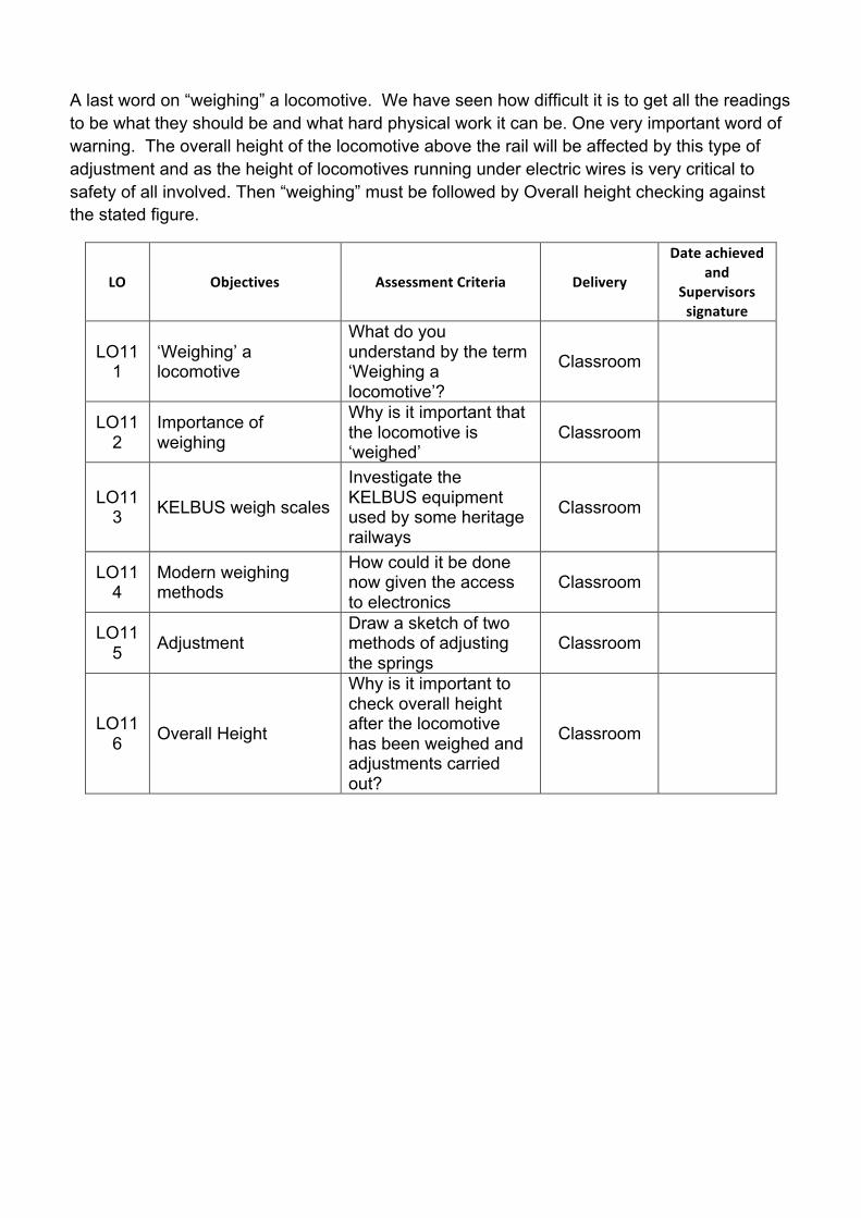
A last word on “weighing” a locomotive. We have seen how difficult it is to get all the readings to be what they should be and what hard physical work it can be. One very important word of warning. The overall height of the locomotive above the rail will be affected by this type of adjustment and as the height of locomotives running under electric wires is very critical to safety of all involved. Then “weighing” must be followed by Overall height checking against the stated figure.
LO Objectives AssessmentCriteria Delivery
Dateachievedand
Supervisorssignature
LO11 1
‘Weighing’ a locomotive
What do you understand by the term ‘Weighing a locomotive’?
Classroom
LO11 2
Importance of weighing
Why is it important that the locomotive is ‘weighed’
Classroom
LO11 3 KELBUS weigh scales
Investigate the KELBUS equipment used by some heritage railways
Classroom
LO11 4
Modern weighing methods
How could it be done now given the access to electronics
Classroom
LO11 5 Adjustment
Draw a sketch of two methods of adjusting the springs
Classroom
LO11 6 Overall Height
Why is it important to check overall height after the locomotive has been weighed and adjustments carried out?
Classroom

LO12
Roller bearing axleboxes with cannon-box design.
1. Why use roller bearings? 2. Advantages 3. Disadvantages 4. Cannon Box design
Several of the Standard Class of steam locomotives introduced by British Railways in the 1950s were built with roller bearings.
There had been experiments with the mixed traffic Black Five built by various builders to experiment with rolling contact bearings on coupled wheels. These experiments it was found that it was easy to equip the tenders with roller bearings as the bearing was carried outside the wheelset but it was more difficult to do that replacement for bearings on the driving wheels. There were two problems. Firstly was the fact discussed previously where accommodating vertical axlebox movement was facilitated by setting the bearings in a so called cannon-box which prevented the bearings getting distorted as one lifted. The two bearings were kept together as a pair. However if any bearing maintenance was required then the driving wheels had to come off the axle which was a big set -back. These disadvantages had to be set against the minimal need for maintenance other than occasional greasing compared with what had gone before with friction bearings.
The cannon-box design with roller bearings did have the advantage that it protected the bearings below from ingress of dirt from above.
LO Objectives AssessmentCriteria Delivery
Dateachievedand
Supervisorssignature
LO12 1
Why use Roller bearings
Why would engineers like to move to use roller bearings?
Classroom
LO12 2
Advantages of using roller bearings
List 2 advantages of using roller bearings Classroom
LO12 3
Disadvantages of use roller bearings
List 2 disadvantages of roller bearings Classroom
LO12 4 Cannon box design
Draw a sketch of a cannon roller bearing box
Classroom

On completion of the module the trainee should be able to use correctly and safely the
following equipment:
• Measuring instruments
• Hand Tools
Assessment
Learners could demonstrate competence in this unit by:
• Documental evidence
• Photographic evidence
• Witness statements e.g. written or verbal statement from a competent person stating that they have completed tasks satisfactorily.
• Underpinning knowledge questions e.g. written questions, multi choice answer sheets, on‐line tests, and assignments.
• Practical training tasks