Steam generator mod. A - Mazzi Arturo
27
ASSEMBLY AND USE INSTRUCTIONS Steam generator mod. A
Transcript of Steam generator mod. A - Mazzi Arturo
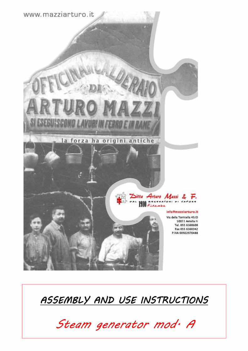
ASSEMBLY AND USE INSTRUCTIONS
Steam generator mod. A

2
3
FOREWORD (Read this section very carefully)
The manufacturer is not liable for any damages to people, animals and/or property arising
from use of the product not in conformity with the instructions given in this Manual, for
improper use of for failure to carry out the maintenance operations indicated in this Manual.
The manufacturer has implemented all the provisions of the regulations in force and has designed
the equipment to reduce risks and with the safety systems available on the market. However,
residual risks are still possible, and their prevention is a responsibility of the user, who shall
observe the instructions given in this Use and maintenance manual.
Do not touch the boiler hot parts and its accessories, marked with the label below.
Yellow triangular sticker: HOT PART
4
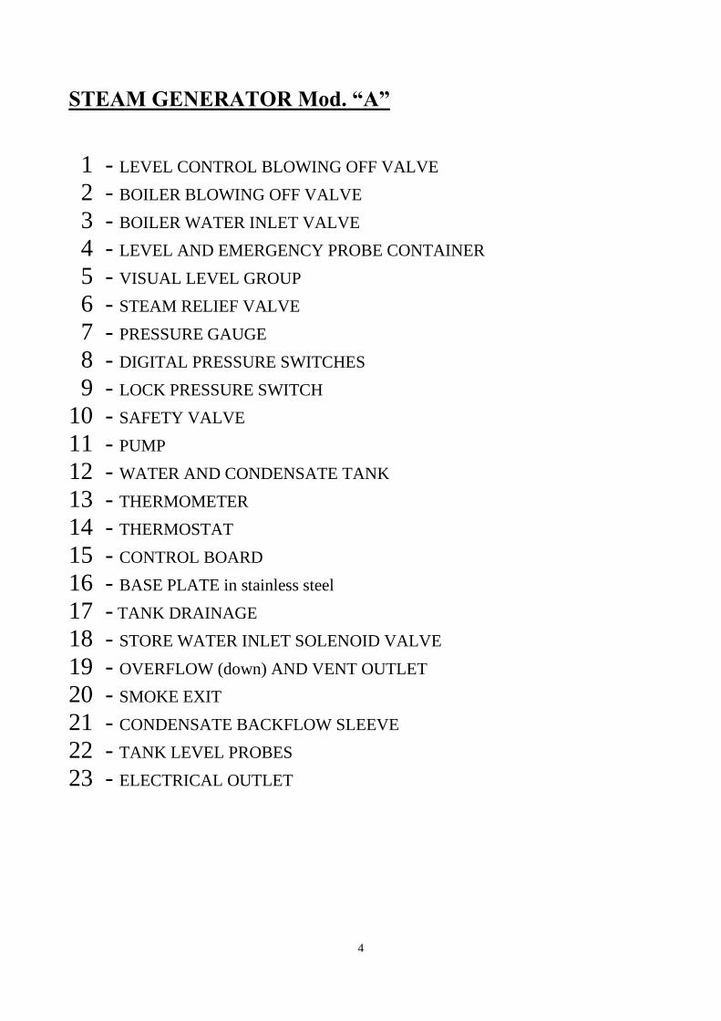
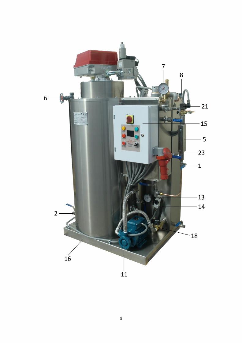
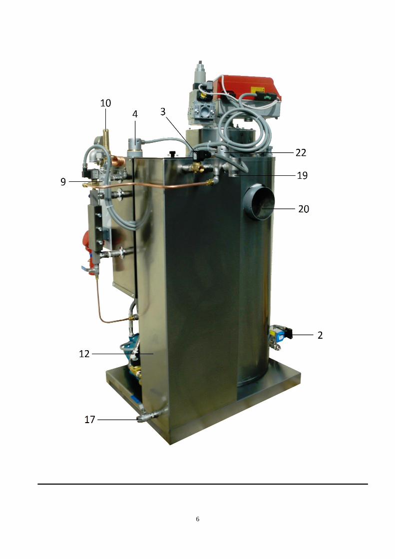
STEAM GENERATOR Mod. “A”
1 - LEVEL CONTROL BLOWING OFF VALVE
2 - BOILER BLOWING OFF VALVE
3 - BOILER WATER INLET VALVE
4 - LEVEL AND EMERGENCY PROBE CONTAINER
5 - VISUAL LEVEL GROUP
6 - STEAM RELIEF VALVE
7 - PRESSURE GAUGE
8 - DIGITAL PRESSURE SWITCHES
9 - LOCK PRESSURE SWITCH
10 - SAFETY VALVE
11 - PUMP
12 - WATER AND CONDENSATE TANK
13 - THERMOMETER
14 - THERMOSTAT
15 - CONTROL BOARD
16 - BASE PLATE in stainless steel
17 - TANK DRAINAGE
18 - STORE WATER INLET SOLENOID VALVE
19 - OVERFLOW (down) AND VENT OUTLET
20 - SMOKE EXIT
21 - CONDENSATE BACKFLOW SLEEVE
22 - TANK LEVEL PROBES
23 - ELECTRICAL OUTLET
5
6
7
8
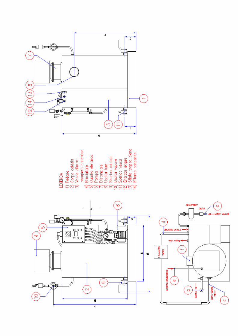
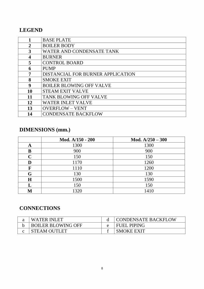
LEGEND
1 BASE PLATE
2 BOILER BODY
3 WATER AND CONDENSATE TANK
4 BURNER
5 CONTROL BOARD
6 PUMP
7 DISTANCIAL FOR BURNER APPLICATION
8 SMOKE EXIT
9 BOILER BLOWING OFF VALVE
10 STEAM EXIT VALVE
11 TANK BLOWING OFF VALVE
12 WATER INLET VALVE
13 OVERFLOW – VENT
14 CONDENSATE BACKFLOW
DIMENSIONS (mm.)
Mod. A/150 - 200 Mod. A/250 – 300
A 1300 1300
B 900 900
C 150 150
D 1170 1260
F 1110 1200
G 130 130
H 1500 1590
L 150 150
M 1320 1410
CONNECTIONS
a WATER INLET d CONDENSATE BACKFLOW
b BOILER BLOWING OFF e FUEL PIPING
c STEAM OUTLET f SMOKE EXIT
9
INSTALLATION INSTRUCTIONS
Heating plant
The heating plant room must comply with the regulations in force based on the steam generator
power.
In any case, the room must:
- exhibit such height so that in its highest point, the generator is at least 1 metre away from the
ceiling
- have a free space in front and behind the generator as needed for maintenance and cleaning
operations
- be properly lighted, ventilated and easy to access.
Stack
The stack must be sealed, smooth and properly insulated.
In systems with multiple generators, each generator must have a separate stack insulated from the
adjacent ones.
No other exhaust may be connected to the generator stack.
In installing the stack, avoid small-radius curves as much as possible; in any case, do not install
sections with slope below 5%.
The stack top must be at least 1 metre above the ridge of the roof of any other building at a distance
of less than 10 metres from the boiler room.
Burner assembly
Foreword
For boilers supplied without burner, observe all the instructions given below. Use only
burners of the type and with the features recommended in the boilers' technical sheets. When
this is not possible, use burners with similar features and of equal or lower power. In this
case, our written AUTHORISATION is required.
The steam generator is provided with a blind plate to install any type of burner.
If a two-stage burner is installed, please refer to paragraph 2.2 on page 14 to ensure proper
operation of the burner.
If the burner is supplied with gas oil, use 45° nozzles.
Please note that a proper regulation of the flame inside the furnace is essential for the steam
generator to work properly, as this is pressurised equipment and an improper regulation can
seriously damage the generator.
The manufacturer recommends making the above regulation very carefully and declines all liability
if regular combustion parameters are not observed.
Feeding water
The generator efficiency, reliability and useful life mostly depend on the states of its inner surfaces.
The steam generator feeding water must therefore be suitably treated to prevent scaling and
corrosion that may occur for the reasons described in paragraph “Notes on the feeding water”, on
page 24 of this Manual.
10
The system for such treatment should be selected according to the water characteristics; it is
therefore necessary to make an accurate analysis of the feeding water before using the steam
generator.
The manufacturer declines all liability for damages caused to the steam generator if the feeding
water exhibits values exceeding the limits indicated in Table 1 below.
Table 1
Parameters Unit of measurement Limit value
Total hardness French degrees (° F) 3
Oxygen mg/l 0.1
Ph min. 6,5 – max. 9
Alkalinity P mg/l da 300 a 1000
Conductivity at 25° µS 2000
Total iron mg/l 0.1
Once a suitable water treatment system has been installed, the user must ensure that the aqueduct
pressure is sufficient to operate the water softener (min. 1.5 – max. 7); if not, an autoclave must be
installed.
The user must also perform the following periodical checks:
- check the water hardness to ensure that the water conditioning system is in good working order
- after 10/15 work days, analyse the water into the store so check its reactivity degree and type,
that is, whether it is acid or alkaline. based on the results, if needed, condition the water using
special additives
- check that the water softener consumes the right amount of salt and therefore carries out its
conditioning properly
- perform regular daily and weekly drainage, as explained in the following paragraph, "Drainage”,
on this page of the Manual
- periodically check that water pressure in the softener is within the prescribed limits; if not,
carefully clean the softener filter or remove any cause of such pressure drop.
Drainage
Water is softened with ion exchange resins that replace calcium and magnesium ions in water with
sodium ions.
This removes calcium, which cause inside scale, but keeps the concentration of salts that tend to
accumulate on the bottom of the generator unchanged.
It is therefore necessary to eliminate this scale with proper drainage operations that must be carried
out at fixed intervals as described below:
- every day, when the system is started and the pressure switch reads 0.5 bar, drain the blowing
off valve (no. 2) for some seconds
- periodically (approx. every week) drain also the level control blowing off valve (no. 1)
following the same procedure, opening the blowing off ball valve of the visual level group (no.
5)
- at the end of the weekly working cycle, fully drain the boiler from the blowing off valve (no. 2).
IMPORTANT: THE STEAM GENERATOR MUST NOT STAY EMPTY AFTER WATER IS FULLY
DRAINED.
To this end, after the full drainage of the steam generator, close the blowing off valves no. 2 and no.
1 and turn on the master switch of the control board to make the pump restore water inside the
generator.
When water reaches the maximum level, switch off the control board.
11
Condensate backflow
The feeding store located next to the steam generator can also be used for condensate backflow; in
this way, the generator is supplied with hot water, this allowing high energy saving.
However, if the condensate amount is high and continuous, the feeding water may overheat, thus
causing pump suction problems.
To this end, the above store is supplied equipped with thermometer, thermostat and solenoid valve.
Setting the thermostat to an approximate temperature of 60-70° C, if the water contained into the
store exceeds this value, the solenoid valve opens and drains a certain amount of water from the
overflow; at the same time, the probe restores the cold water from the supply and restores the proper
temperatures inside the store.
HOW TO INSTALL THE STEAM GENERATOR
All connections to the steam use mains must be made by a flexible joint suitable for the steam
temperature and pressure.
Pipe the level control drain valve (no. 1) and the boiler drain valve (no. 2) with special piping.
Pipe the safety valve drainage (no. 10) so as to not cause damages to people or property
(preferably outside the boiler room)
Bring the cold water inlet piping from the softener to the stainless steel tank (no. 12) through the
solenoid valve connection (n. 18)
Pipe the stainless steel tank drainage (n. 17) with the overflow outlet (n. 19).
Pipe the system condensate backflow piping to the sleeve (n. 21) of the tank
Set the thermostat temperature (n. 14) to about 60/70° C.
Connect the gas piping to the burner, installing a pressure regulator to be set to the pressure
value of 400/450 mm. for LPG and 180/200 mm. for natural gas
If a two-stage burner is installed, connect the wires from the control board as follows:
WHITE WIRE = COMMON
RED WIRE = NORMALLY CLOSED (NC)
as indicated in paragraph 2.2 on page 14
Connect the steam generator smoke outlet to the boiler room flue with draught according to the
regulations in force.
12
START-UP INSTRUCTIONS
Once all fuel pipes, feeding and drainage water, steam intake, smoke exhaust, and electrical line
connections have been made, the generator is ready to operate.
Before it is started up, check that the water inlet cock is open and that the boiler drain cocks and
the level control are closed.
Switch on the control board by the external master switch: the pump will start delivering water
up to the level set (if the pump direction of rotation is opposite to the direction shown by the arrow on the pump,
reverse two phases on the control board).
When the pump stops, the manual reset indicator on the control board will turn on; press the
blue button to release it and start the burner.
To operate the control board, refer to the specifications below.
TECHNICAL AND FUNCTIONAL SPECIFICATIONS
OF THE LOGO! 24 BOILER CONTROLLER
FOREWORD – This document describes the technical and functional specifications of the
integrated controller for LOGO! 24 industrial boilers.
SYSTEM – The controller is contained in a metal case with IP 55 protection degree, divided into
two zones: Low Voltage – Control Logic, and High Voltage – Actuator Control.
The two light buttons, a green one and a blue one, have the following functions: GREEN light button PUMP ON = indicates that the water backflow pump is operating; it also
starts the pump hand control
BLUE light button MANUAL RESET = indicates a boiler lock state. When the light is solid, it
indicates a "no water" alarm; when the light is flashing, it indicates a "maximum pressure"
alarm. The three light indicators have the following functions:
WHITE indicator SYSTEM ON = indicates that the system is on and live
GREEN indicator BURNER ON = indicates that the burner is on
YELLOW indicator PUMP LOCKED = indicates that the pump is in a temporary thermal lock
The 2-position knob selector has the following functions:
ON position = solenoid valve on
OFF position = solenoid valve off
The door lock switch prevents the metal case door opening when it is live.
The control electronics is implemented by the LOGO!24 PLC.
The alphanumerical display shows some diagnostic messages for the system operation.
SYSTEM POWER SUPPLY – The system is powered with three-phase 380 V + neutral voltage,
controlled by a special remote control switch to control the system pump. A phase + neutral of the
supply voltage is provided to control the burner (by a special relay) and for the transformer that
powers the logical section.
The transformer has a 220 V input and provides 24 V alternating voltage used for the pump and
burner remote control switch coils.
This alternating voltage is also sent to the LOGO!24 PLC and supplies voltage to the display and to
the microcontroller.
13
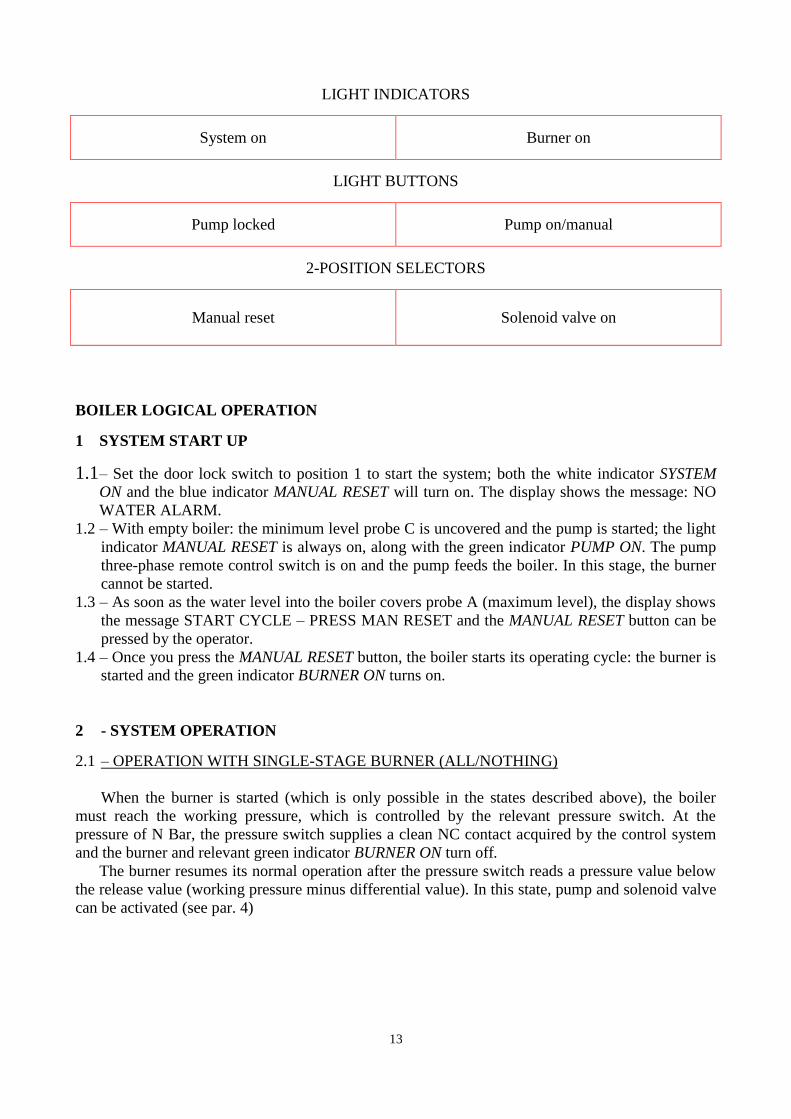
LIGHT INDICATORS
System on
Burner on
LIGHT BUTTONS
Pump locked
Pump on/manual
2-POSITION SELECTORS
Manual reset
Solenoid valve on
BOILER LOGICAL OPERATION
1 SYSTEM START UP
1.1 – Set the door lock switch to position 1 to start the system; both the white indicator SYSTEM
ON and the blue indicator MANUAL RESET will turn on. The display shows the message: NO
WATER ALARM. 1.2 – With empty boiler: the minimum level probe C is uncovered and the pump is started; the light
indicator MANUAL RESET is always on, along with the green indicator PUMP ON. The pump
three-phase remote control switch is on and the pump feeds the boiler. In this stage, the burner
cannot be started. 1.3 – As soon as the water level into the boiler covers probe A (maximum level), the display shows
the message START CYCLE – PRESS MAN RESET and the MANUAL RESET button can be
pressed by the operator.
1.4 – Once you press the MANUAL RESET button, the boiler starts its operating cycle: the burner is
started and the green indicator BURNER ON turns on.
2 - SYSTEM OPERATION
2.1 – OPERATION WITH SINGLE-STAGE BURNER (ALL/NOTHING)
When the burner is started (which is only possible in the states described above), the boiler
must reach the working pressure, which is controlled by the relevant pressure switch. At the
pressure of N Bar, the pressure switch supplies a clean NC contact acquired by the control system
and the burner and relevant green indicator BURNER ON turn off.
The burner resumes its normal operation after the pressure switch reads a pressure value below
the release value (working pressure minus differential value). In this state, pump and solenoid valve
can be activated (see par. 4)
14
2.2 – OPERATION WITH TWO-STAGE BURNER (HIGH/LOW)
The working pressure and modulation pressure are regulated by the digital pressure switch.
This function differentiates the fuel delivery rate according to the different work phases, based
on the user’s steam requirements.
In this condition, the burner starts with the two work stages (low and high flame), until it
reaches the pressure setted on the digital pressure switch.
When this value is reached, the low flame starts until the working pressure is reached.
As steam is drawn, the working pressure drops below the value set on the digital pressure
switch and then, the high flame starts until the above value is reached, as described above.
The two wires from the control board provide the following contacts:
WHITE WIRE = COMMON
RED WIRE = NORMALLY CLOSED (NC)
Do a jumper between T1 and T2, on the terminal board.
3 – SAFETY DEVICES
The system is provided with the following safety systems:
- lock probes C
- manual reset safety pressure switch
3.1 – When one or both probes C are not acquired by the control system (dirty probes or electrical
connection failure), even though the level restoration probe B and/or the max level probe A
detect the presence of water into the boiler, a lock state is triggered, as shown by the MANUAL
RESET button, which turns on, and by the message NO WATER ALARM on the display. In this state, the burner is not active. To restore proper operation, probes C must be properly
working, along with probes A and B.
Following correct restoration of these probes, the boiler can be reset (by the MANUAL
RESET button). Once this button is pressed, the boiler restores its cycles from where it had been
interrupted. 3.2 If the working pressure switch does not supply the NC contact to the control system due to a
failure, and the working pressure exceeds the threshold set, the manual reset lock pressure
switch triggers.
The indicator MANUAL RESET on the panel turns on, flashing, and the message
MAXIMUM PRESSURE ALARM is shown on the display.
In this state, check the reasons of the working pressure switch failure.
Once the causes have been eliminated, you can restore the system pressing the release button
located on the safety pressure switch, and then pressing the flashing button MANUAL RESET
on the control board.
The safety pressure switch release button can be reset only when the boiler is not
pressurised; it is therefore necessary to release the generator pressure before the safety pressure
switch can be reset.
15
4 – HAND SELECTOR AND BUTTON OPERATION
4.1 - Solenoid valve operation: during normal operation, the system can start a solenoid valve to
make water flow out of the condensate store if water contained therein becomes overheated.
To this end, the SOLENOID VALVE ON knob selector, located on the control board, must
always be set to ON.
4.2 – Pump manual valve operation: the PUMP ON/MANUAL button can be pressed in any
situation.
This operation may be needed to manually restore water level into the boiler, in the conditions
described at 2.2 and 2.3 in emergency situations, when a certain working phase has to be completed.
In this situation, however, check the reasons of the lack of water and operate accordingly.
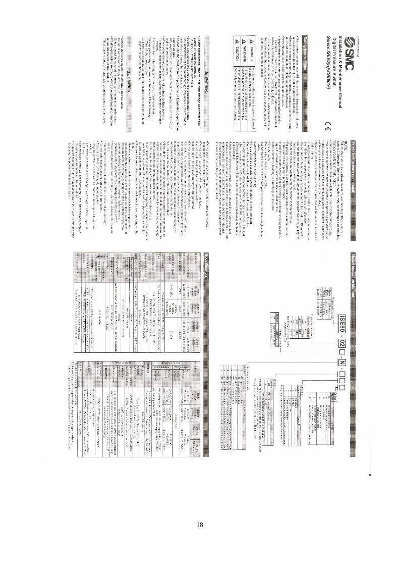
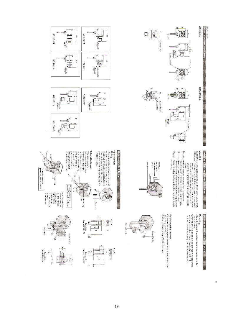
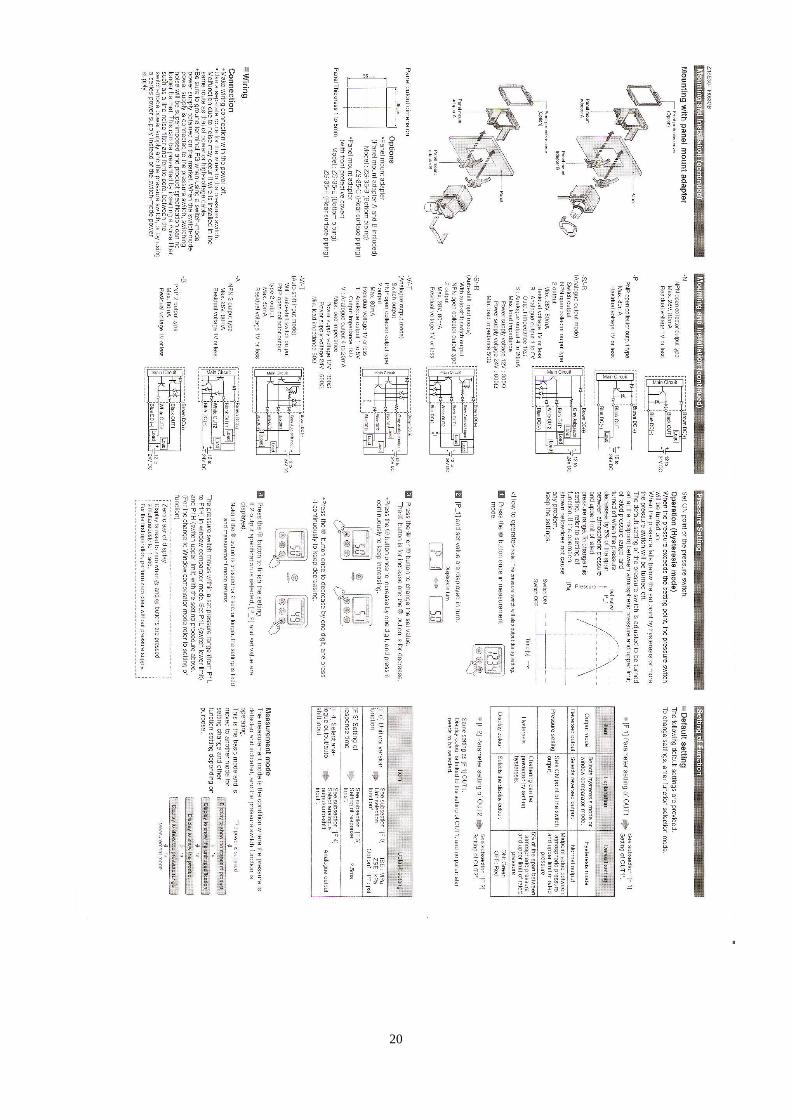
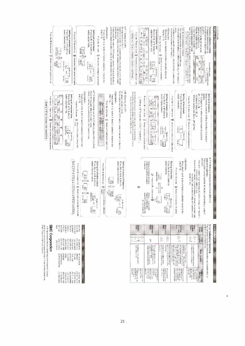
For DIGITAL PRESSURE SWITCH instructions, please see the instructions at pages 18 - 21
WARNING
In the event of a temporary or extended voltage cutout, the equipment could lock up and
display the following message:
PROGRAM
PC—LOGO
START
In this case, proceed as follows:
- using the vertical triangular buttons, move the arrow to START and press OK
Never press OK when the arrow is on PROGRAM
By this operation, the equipment resumes its regular operation.
If it does not, or if you have any doubts, contact the suppliers without making further
attempts.
16
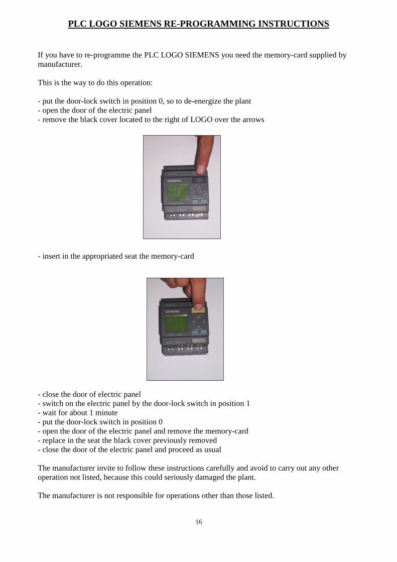
PLC LOGO SIEMENS RE-PROGRAMMING INSTRUCTIONS
If you have to re-programme the PLC LOGO SIEMENS you need the memory-card supplied by
manufacturer.
This is the way to do this operation:
- put the door-lock switch in position 0, so to de-energize the plant
- open the door of the electric panel
- remove the black cover located to the right of LOGO over the arrows
- insert in the appropriated seat the memory-card
- close the door of electric panel
- switch on the electric panel by the door-lock switch in position 1
- wait for about 1 minute
- put the door-lock switch in position 0
- open the door of the electric panel and remove the memory-card
- replace in the seat the black cover previously removed
- close the door of the electric panel and proceed as usual
The manufacturer invite to follow these instructions carefully and avoid to carry out any other
operation not listed, because this could seriously damaged the plant.
The manufacturer is not responsible for operations other than those listed.
17
INSTRUCTIONS TO PROGRAM THE DIGITAL PRESSURE SWITCH
The digital pressure switch is already programmed to the plate values of the steam
generator, with a differential of 0.2 bar.
The parameters that can be modified by the user are:
- working pressure
- pressure modulation to work with two-stage burner
To change these values should do the following:
• Press the "S"
• the display shows alternately the symbol "n-1" and the value of pressure preset
• through the up-down arrows, change the value to the desired pressure
• press the button "S"
• the display shows alternately the symbol "n-2" and the pressure modulation reset
• to modify this value, proceed as described above using the arrows up / down
• for not to modify this value press the switch "S"
If you need to replace the digital pressure switch, contact the company Mazzi for the
correct setting of parameters.
In case of particular malfunction, refer to the instruction manual of the digital
pressure switch or contact the company Mazzi.
18
19
20
21
22
MAINTENANCE INSTRUCTIONS
The maintenance operations to carry out on the steam generator are:
- by the user:
a) periodically clean the condensate backflow and feeding store.
b) every 6 (six) months (or every time the levels are not working properly), clean the probe
ends using an emery cloth.
c) check the water treatment efficiency, as described in paragraph “Feeding water”, on page 6
of this Manual.
- by a skilled Technician authorised by the manufacturer:
d) every 6 (six) months, at the installation site, carry out a general check of the equipment, in
particular check the efficiency of all safety devices
- by the manufacturer or a laboratory appointed by them:
e) 10 (ten) years after the first installation, carry out an extraordinary maintenance check at the
manufacturer or an expressly appointed laboratory to have the equipment checked, and all
inefficient parts replaced; this extraordinary maintenance should afterwards be repeated
every 3 (three) years, until the steam generator is used.
N.B. All maintenance, service and replacement operations carried out on the boiler assembly
must be registered on the sheets enclosed at the end of this Manual.
23
OPERATING FAULTS – Problems and solutions
1 – The blue “Manual reset” indicator turns on during operation:
1a – Blue indicator with solid light = no water alarm
1a r
2a r
3a r
4a r
Check if water is actually short inside the generator (through the visual level no. 5)
If water is short, check the reason and manually refill up to the max level.
If the visual level shows the presence of water into the generator:
clean the end of the probes located in the level control (especially safety probe and lock
probe B and C) using an emery cloth.
Check that the probe electrical wires are properly connected, according to the board
wiring diagram. Check whether the water level into the boiler is subject to sudden changes (through the
visual level no. 5); in that case, fully drain the boiler several times to remove any traces
of greasiness inside. If needed, wash with a specific degreasing product.
1b – Blue indicator with flashing light = maximum pressure alarm
1b r
2b r
Check the water level into the boiler (through the visual level no. 5)
If the level is fully covered with water:
Clean the end of the probes located in the level control (especially minimum and
maximum level probes A and B) using an emery cloth
If the water level into the boiler is regular:
Check whether the safety pressure switch has locked up.
In that case, check the efficiency of the work pressure switch and replace it, if faulty:
then, press the safety pressure switch manual reset button.
2 – The burner won’t start up
1 r
2 r
3 r
Check that the boiler is at the proper level; if not, check the reasons.
Check the work pressure switch (no. 8) and the lock pressure switch (no. 9) efficiency.
Check the efficiency of contactor and fuses inside the control board.
3 – Water leaks from the level indicator group
1 r
Close the valves (no. 5) and check if the seals need replacement.
24
NOTES ON THE FEEDING WATER
Water suitable for feeding steam boilers must exhibit certain characteristics that are not
always found in the water available for this use, where several harmful components are often
contained:
DISSOLVED GASES: carbon dioxide, oxygen, nitrogen.
SUBSTANCES THAT CAUSE SCALING: calcium carbonates, magnesium carbonates, gypsum,
silicates, aluminates, ferrous carbonate.
SOLUBLE BUT HARMFUL SALTS: sodium chloride, magnesium chloride, magnesium phosphate. OCCASIONAL IMPURITIES: organic substances, mineral acids, ammonia, etc.
Dissolved gases, such as O and CO, corrode the generator walls as they cause the
formation of rust; such corrosion is also favoured by the presence of sodium chloride.
Scaling is produced by the formation of insoluble compounds through chemical
reactions or solubility influence regulated by the chemical balance.
Scaling can be calcareous, magnesian, gypseous, and siliceous if consisting, respectively, of:
calcium carbonate, magnesium carbonate, calcium sulphate and silicates.
As scaling is not highly heat conductive it increases fuel consumption, thus reducing the
generator efficiency and finally damaging it, as steel is not in direct contact with water and
therefore overheats up to burning.
For this reason, the feeding water must be free from scaling substances, gas, oil and
suspended substances, as much as possible.
Scaling substances also cause the inefficiency of the boiler body pipes; gases and air, on the
other hand, cause corrosion of the entire boiler whereas very fine suspended substances cause foams
and thereby produce polluted damp steam containing salts, thus being very dangerous for the
generator.
Water must be carefully treated, softened and, if necessary, deferrized or degassed, and
must be freed from any impurities, especially oil; these operations must be carried out using
chemical means.
Suspended substances are eliminated by sedimentation and filtration, two essential
operations for waters derived from artesian wells.
25
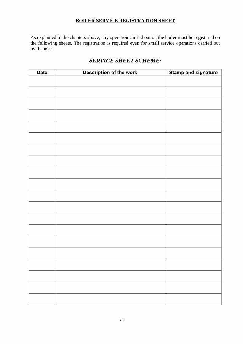
BOILER SERVICE REGISTRATION SHEET
As explained in the chapters above, any operation carried out on the boiler must be registered on
the following sheets. The registration is required even for small service operations carried out
by the user.
SERVICE SHEET SCHEME:
Date Description of the work Stamp and signature
26
Date Description of the work Stamp and signature
27
di Ugo Mazzi – successore Mazzi Alessandra
Via Sandro Pertini, 12 – 50012 ANTELLA – Firenze – Tel. 055.65.60.608 – Fax 055.65.60.342 [email protected] - www.mazziarturo.it - www.paginegialle.it/mazziarturo
RE: STEAM GENERATOR MOD. N. F
Guarantee Terms
The generator pressure body is guaranteed for 12 (twelve) months from the date of delivery.
The sub-suppliers terms apply to all the other generator components.
During the guarantee term, all faulty parts shall be replaced or repaired, free of charge at the manufacturer’s
premises, whereas travelling expenses for the service staff working at the installation site shall be borne by the
purchaser.
The guarantee becomes void in the following cases:
- failure to keep the materials in an appropriate place
- failure to comply with the regulations in force regarding equipment safety
- inappropriate chemical washing of pressurised parts
- presence of scaling, corrosion, mud, excessive alkalinity, due to inappropriate feeding water treatment
- lack of running and maintenance operations
- tampering of the equipment
- operating by unauthorised or unskilled staff
- failure to comply with the operating instructions given in this Manual
- irregular electrical, fuel and water supply
Parts subject to normal wear are not covered by this guarantee
Any performance tests shall be carried out within 6 (six) solar months from the date of delivery. Any charges for
the above tests shall be borne by the purchaser
MAZZI ARTURO & F.