STC Solenoid Valve Owner’s Manual —STC Solenoid Valve ... Solenoid... · STC Solenoid Valve...
2
STC Solenoid Valve Owner’s Manual Warning: Be aware of the pressure levels of your system. STC Solenoid valves are designed for air flow only. Make sure the pilot source is operating at pressures specified for the valve. Solenoid Valves Installation Procedure A. Attaching Tubing to Valves: Attach a connector to the desired port on the valve body. Push the tubing into the connector until it comes to a stop. Pull the tubing back gently until the Grip Ring or Collet grips onto the tubing and has a good seal. B. Installing a Valve onto a Manifold Manifolds can fit 2, 4, 6, 8 and 16 valves. Secure screws until the component will not move freely, and then tighten another quarter turn. 1. Place a rubber seal over the manifold openings. 2. Line up the valve with port “A” and corresponding pilot holes for the screws. 3. Secure the valve into place. 4. Cover the remaining holes with gaskets. C. General Valve Installation Connect the source to the port labeled “P” Connect the first outlet to the port labeled “A” Connect the first exhaust to the port labeled “EA” Connect the second outlet to the port labeled “B” Connect the second exhaust to the port labeled “EB” StcValve.com; 650-856-8833 PUB: PUB 2012—STC Solenoid Valve Owner’s Manual Port Diagram (4-way air pilot valve shown) Exhaust for Port “A” Pilot Port Exhaust for Port “B” First Outlet Port Second Outlet Port Air Pilot End Cap Air Pilot Port
Transcript of STC Solenoid Valve Owner’s Manual —STC Solenoid Valve ... Solenoid... · STC Solenoid Valve...
STC Solenoid Valve Owner’s Manual
Warning: Be aware of the pressure levels of your system. STC Solenoid valves are designed for air flow only. Make
sure the pilot source is operating at pressures specified for the valve.
Solenoid Valves Installation Procedure
A. Attaching Tubing to Valves:
Attach a connector to the desired port on the valve body.
Push the tubing into the connector until it comes to a stop.
Pull the tubing back gently until the Grip Ring or Collet
grips onto the tubing and has a good seal.
B. Installing a Valve onto a Manifold
Manifolds can fit 2, 4, 6, 8 and 16 valves.
Secure screws until the component will not move freely,
and then tighten another quarter turn.
1. Place a rubber seal over the manifold openings.
2. Line up the valve with port “A” and corresponding pilot
holes for the screws.
3. Secure the valve into place.
4. Cover the remaining holes with gaskets.
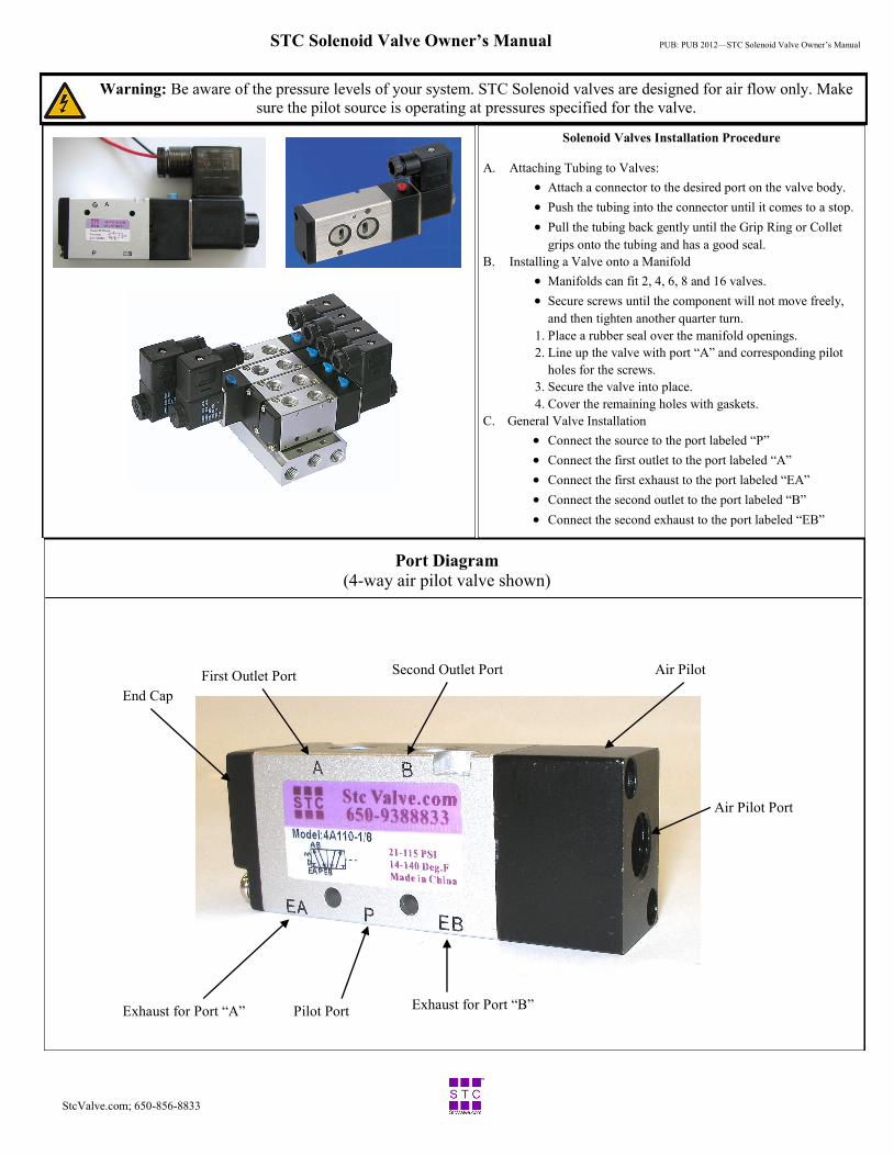
C. General Valve Installation
Connect the source to the port labeled “P”
Connect the first outlet to the port labeled “A”
Connect the first exhaust to the port labeled “EA”
Connect the second outlet to the port labeled “B”
Connect the second exhaust to the port labeled “EB”
StcValve.com; 650-856-8833
PUB: PUB 2012—STC Solenoid Valve Owner’s Manual
Port Diagram (4-way air pilot valve shown)
Exhaust for Port “A” Pilot Port Exhaust for Port “B”
First Outlet Port Second Outlet Port Air Pilot
End Cap
Air Pilot Port
STC Solenoid Valve Owner’s Manual Pg. 2
Warning: Be aware of the pressure levels of your system. STC Solenoid valves are designed for air flow only. Make
sure the pilot source is operating at pressures specified for the valve.
StcValve.com; 650-856-8833
PUB: PUB 2012—STC Solenoid Valve Owner’s Manual
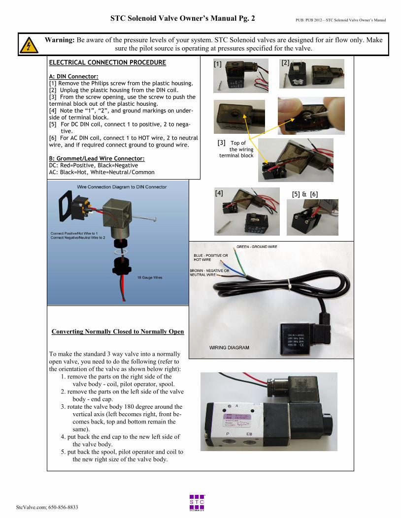
ELECTRICAL CONNECTION PROCEDURE
A: DIN Connector: [1] Remove the Philips screw from the plastic housing. [2] Unplug the plastic housing from the DIN coil. [3] From the screw opening, use the screw to push the terminal block out of the plastic housing. [4] Note the “1”, “2”, and ground markings on under-side of terminal block. [5] For DC DIN coil, connect 1 to positive, 2 to nega-
tive. [6] For AC DIN coil, connect 1 to HOT wire, 2 to neutral wire, and if required connect ground to ground wire. B: Grommet/Lead Wire Connector: DC: Red=Positive, Black=Negative AC: Black=Hot, White=Neutral/Common
[1] [2]
[3] Top of
the wiring terminal block
[4] [5] & [6]
Converting Normally Closed to Normally Open
To make the standard 3 way valve into a normally
open valve, you need to do the following (refer to
the orientation of the valve as shown below right):
1. remove the parts on the right side of the
valve body - coil, pilot operator, spool.
2. remove the parts on the left side of the valve
body - end cap.
3. rotate the valve body 180 degree around the
vertical axis (left becomes right, front be-
comes back, top and bottom remain the
same).
4. put back the end cap to the new left side of
the valve body.
5. put back the spool, pilot operator and coil to
the new right size of the valve body.