
Status Report on current and future Geostationary Indian ...
Status Report on current and future Geostationary Indian Satellites
By
Dr. Devendra SinghDirector
Satellite MeteorologyIndia Meteorological Department
New Delhi-110003

SATELLITE METEOROLOGY DIVISION IMD, NEW DELHI
INSAT SATELLITES
NOAA SATELLITES
EUMETSAT SATELLITES
METEOROLOGICAL DATA DISSEMINATION
MDD
CYCLONE WARNING DISSEMINATION SCHEME
CWDS
DATA COLLECTION PLATFORMDCP
INDO – US DATA EXCHANGE CENTRE
PROCESSING OF CONVENTIONAL DATA FROM GTS
Receives, processes,Archives, generates Meteorological Productsfrom

1982
1992
1999
2002
2003
INSAT-1Multipurpose (MP)
VIS 2.75 Km.IR 11.0 Km.
VIS 2.0 Km.IR 8.0 Km.
INSAT-2Multipurpose (MP)
VIS 2.0 Km.IR 8.0 Km.WV 8.0 Km.
INSAT-2E(MP)
2007
Dedicated MET Mission KALPANA-1
VIS 2.0 Km.IR 8.0 Km.
WV 8.0 Km.
VIS 2.0 Km.IR 8.0 Km.WV 8.0 Km.
+ CCDINSAT-3A(MP)
INSAT-3D
3 Channel CCD each of1 Km. resolution+
•Multichannel Imager•Sounder
LADDER OF PROGRESS IN THEMETEOROLOGICAL CAPABILITIESOF INDIAN GEOSTATIONARY SATELLITES(INSAT PROGRAMME).
•Multichannel Imager(SIVRI type)•Hyperspectre Sounder
2015

Operational Indian Geostationary Meteorological Satellites
Kalpana-174°E INSAT-3A
93.5°EINSAT-2E83°E
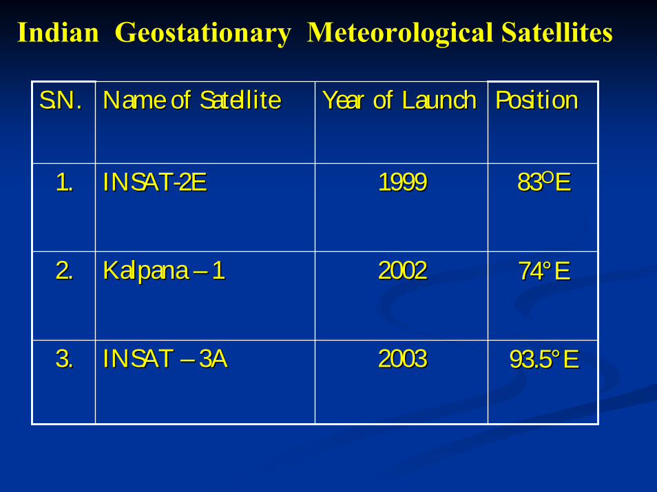
Indian Geostationary Meteorological Satellites
S.N.S.N. Name of SatelliteName of Satellite Year of LaunchYear of Launch PositionPosition
1.1. INSATINSAT--2E2E 19991999 8383OOEE
2.2. KalpanaKalpana –– 1 1 20022002 7474°°EE
3.3. INSAT INSAT –– 3A3A 20032003 93.593.5°°EE

Payloads & channel characteristics of Kalpana – 1
S.NoS.No PayloadPayload ChannelChannel Spectral Spectral BandwidthBandwidth
ResolutionResolution
1.1. VHRRVHRR VisibleVisible 0.55 0.55 -- 0.75 0.75 µµ 2 Km. x 2 Km.2 Km. x 2 Km.
InfraredInfrared 10.5 10.5 -- 12.5 12.5 µµ 8 Km. x 8 Km.8 Km. x 8 Km.
WaterWater
VapourVapour5.7 5.7 -- 7.1 7.1 µµ 8 Km. x 8 Km.8 Km. x 8 Km.
2.2. DRTDRT For Collection & Dissemination of AWS For Collection & Dissemination of AWS data.data.

Payloads and channel characteristics of INSAT-2E and INSAT-3A
ChannelsChannels Spectral RangeSpectral Range ResolutionResolution
VisibleVisible 0.55 0.55 -- 0.75 0.75 µµ 2 Km.2 Km.
InfraredInfrared 10.5 10.5 -- 12.5 12.5 µµ 8 Km.8 Km.
Water Water VapourVapour 5.7 5.7 -- 7.1 7.1 µµ 8 Km.8 Km.
ChannelsChannels Spectral RangeSpectral Range ResolutionResolution
VisibleVisible 0.63 0.63 -- 0.69 0.69 µµ 1 Km.1 Km.
NIRNIR 0.77 0.77 -- 0.86 0.86 µµ 1 Km.1 Km.
SWIRSWIR 1.55 1.55 -- 1.69 1.69 µµ 1 Km.1 Km.
(ii) CCD
(i) VHRR

INSAT-3D FEATURES
• INSAT 3D IS A METEOROLOGICAL SPACECRAFT HAVING 6 CHANNEL IMAGER, 19 CHANNEL SOUNDER, DRT AND S A A &R
• IT IS A MOMENTUM BIASED 3-AXIS STABILISED SPACECRAFT USING STAR SENSOR IN THE CONTROL LOOP.
• IMC/MMC PROVIDED FOR REQUIRED PAYLOAD POINTING
• BI-ANNUAL YAW ROTATION IS PROVIDED TO REDUCE THE PATCH TEMP.
• THE SPACECRAFT WILL BE LOCATED AT 82 DEG. E AND SUB-ORBITAL POINT FALLS OVER INDIA.
• THE LIFT-OFF MASS TO THE SPACECRAFT IS 2000KG, WITH A DRY MASS OF 907 KG.
• GSLV LAUNCH(SHAR) EARLY 2007
• 7.7 YEARS LIFE
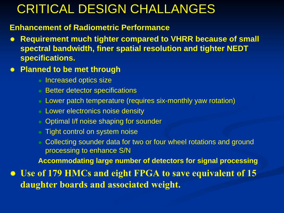
CRITICAL DESIGN CHALLANGESEnhancement of Radiometric Performance
Requirement much tighter compared to VHRR because of small spectral bandwidth, finer spatial resolution and tighter NEDT specifications.Planned to be met through
Increased optics sizeBetter detector specificationsLower patch temperature (requires six-monthly yaw rotation)Lower electronics noise densityOptimal I/f noise shaping for sounderTight control on system noiseCollecting sounder data for two or four wheel rotations and ground processing to enhance S/N
Accommodating large number of detectors for signal processing
Use of 179 HMCs and eight FPGA to save equivalent of 15 daughter boards and associated weight.

New Features of imaging payload1. Modified Blackbody calibration sequence. Here,
fresh space clamp values will be acquired before and after Blackbody view to minimize the effect of I/f noise.
2. Faster sampling of SME HK data to incorporate complete SME data in payload data format at 55 ms rate to avoid dependence on ‘dwell mode TM’ of spacecraft and simplify ground processing and archival.
3. Two flexible modes of operation will be provided instead of three fixed modes of earlier VHRR payloads:
Full frame mode scans 18 EW x 18 NS covering the entire earth disc and some space around.Program mode covering 18 in EW direction NS coverage can be defined in terms of number of lines to be scanned.

INSAT-3D IMAGER CHARACTERISTICS
Band Freq. In um Res. in Km.Visible 0.52-0.75 1.0SWIR 1.55-1.70 1.0MIR 3.80-4.00 4.0WV 6.50-7.00 8.0TIR-1 10.2-11.2 4.0TIR-2 11.5-12.5 4.0
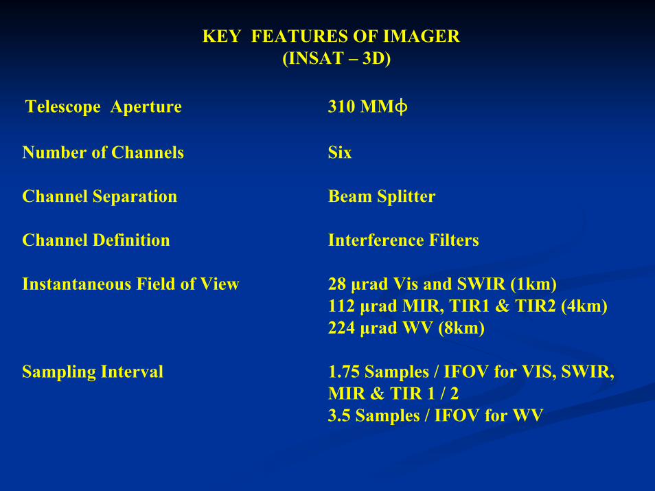
KEY FEATURES OF IMAGER(INSAT – 3D)
Telescope Aperture 310 MMɸ
Number of Channels Six
Channel Separation Beam Splitter
Channel Definition Interference Filters
Instantaneous Field of View 28 µrad Vis and SWIR (1km)112 µrad MIR, TIR1 & TIR2 (4km)224 µrad WV (8km)
Sampling Interval 1.75 Samples / IFOV for VIS, SWIR,MIR & TIR 1 / 23.5 Samples / IFOV for WV

Sampling Interval 1.75 Samples / IFOV for VIS, SWIR,MIR & TIR 1 / 23.5 Samples / IFOV for WV
Scan Step Angle Linear in E-w Direction (8µR step size)Line Step 224 µrad N-S
Scan rate 20 0 / Sec +0.2 sec turn aroundScan Linearity 56 µR (Peak-Peak)Inflight Calibration Full Aperture Blackbody and
spaceview
Scan modes Full, normal and Programmable sectorfor Quick Repeativity
Frame Time 25 minutes for Normal ModeRadiometric Performance See Table 3.1.2Signal Quantisation 10 Bits / SampleDown Link Data Rate 4.0M Bits / Sec

Channel No. Centre Wavelengthµm (cm-1)
Bandwidthµm (cm-1)
NEDT at 300 K(typical) K
1 14.71 (680) 0.281 (13) 1.5
2 14.37 (696) 0.268 (13) 1
3 14.06 (711) 0.256 (13) 0.5
4 13.96 (733) 0.298 (16) 0.5
5 13.37 (749) 0.286 (16) 0.5
6 12.66 (790) 0.481 (30) 0.3
7 12.02(832) 0.723 (50) 0.15
8 11.03 (907) 0.608 (50) 0.15
9 9.71 (1030) 0.235 (25) 0.2
10 7.43 (1345) 0.304 (55) 0.2
11 7.02 (1425) 0.394 (80) 0.2
12 6.51 (1535) 0.255 (60) 0.2
13 4.57 (2188) 0.048 (23) 0.15
14 4.52 (2210) 0.047 (23) 0.15
15 4.45 (2245) 0.0456(23) 0.15
16 4.13 (2420) 0.0683(40) 0.15
17 3.98 (2513) 0.0663 (40) 0.15
18 3.74(2671) 0.140 (100) 0.15
19 0.695 (14367) 0.05(1000) (0.67-0.72)
0.1% albedo
TABLE – 3SPECTRUM AND SENSITIVITY

TABLE –4
KEY FEATURES OF THE SOUNDER (INSAT 3-D)
Telescope Aperture 310 MMΦ
No. of Channels 18 Infrared + 1 Visible
Channel definition Filter Wheel with Interference Filters
Instantaneous field of view 280 µrad x 280 µrad ( N-S )
( 10 km x 10 km )
Sampling Interval 280 µrad E- W /N-S
No. of Simultaneous sounding 4 Per channel
Scan step angle 10 km E-W Every 0.1 Sec. And 40 km N-S
After completion of E-W Scan
150µR(RMs)

Step and Dwell Time 0.1, 0.2 and 0.4 Sec.
Turn Around Time 0.1 per Scan
In-flight Calibration Full Aperture Black Body and Space View
Scan Modes Options provided to cater to Quick Dynamic
Environmental Phenomena
Frame Time 160 minutes for 6000 km 6000 km area
Sounding
Radiometric Performance See Table 3.1.4
Signal Quantisation 13 Bits / Sample
Down Link Data Rate 40 Kbits / Sec
System Power 100 Watts
System Weight 90 Kg (Without Cooler)
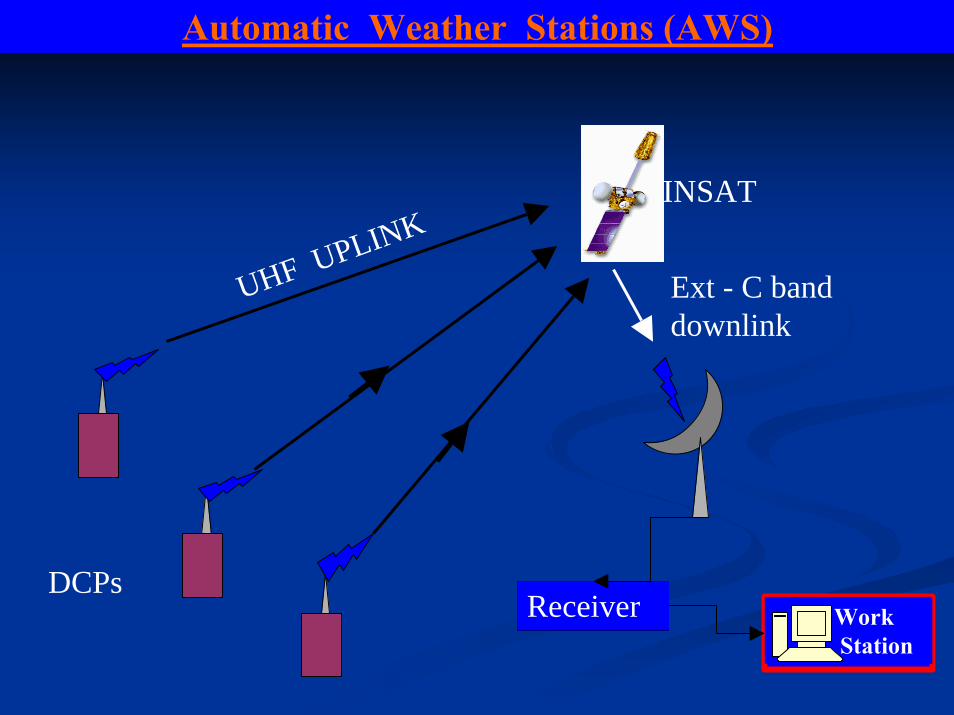
Automatic Weather Stations (AWS)
UHF UPLINKINSAT
Receiver Work Station
Ext - C band downlink
DCPs

Automatic Weather Stations (AWS)
AWS are installed all over the country to take meteorological observations every hour and transmit it to the satellite.
• The Data Relay Transponder on-board the satellite receives these data and retransmit it to Delhi Earth Station of IMD.
• Satellite Division receives these data and processes it to get meteorological data in the required format.
• Data from remote unmanned stations & ocean buoys is also received.

Meteorological Data Dissemination (MDD)
S- band Downlink
Satellite Division
Telecom Division
MDD Receiving Stations in India and neighbouring countries.
C - band uplink
INSAT
Meteorological Data Dissemination (MDD)
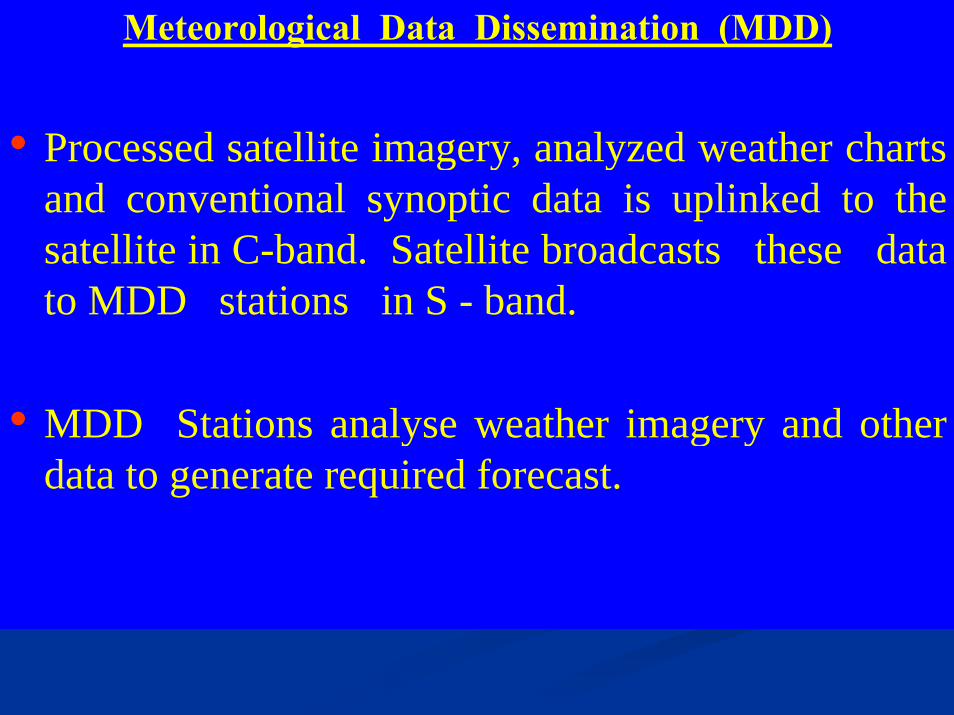
• Processed satellite imagery, analyzed weather charts and conventional synoptic data is uplinked to the satellite in C-band. Satellite broadcasts these data to MDD stations in S - band.
• MDD Stations analyse weather imagery and other data to generate required forecast.
The processing system is also being used for The processing system is also being used for generating analogue type of cloud imagery data which are generating analogue type of cloud imagery data which are transmitted through INSATtransmitted through INSAT--3C to field station using S3C to field station using S--band broadcast capability of the satellite along with other band broadcast capability of the satellite along with other conventional meteorological data and FAX charts. This conventional meteorological data and FAX charts. This scheme is called Meteorological Data scheme is called Meteorological Data Dissemination(MDD). Dissemination(MDD).
There are about 90 MDD receiving stations in the There are about 90 MDD receiving stations in the country being operated by different agencies. Two MDD country being operated by different agencies. Two MDD receiving stations are also operating in receiving stations are also operating in neighbouring neighbouring countries at Sri Lanka and male under bicountries at Sri Lanka and male under bi--lateral lateral agreement. In general, the processed images are sent to agreement. In general, the processed images are sent to these stations every three hours, and every hour during these stations every three hours, and every hour during cyclone periods. These stations are receiving direct cyclone periods. These stations are receiving direct broadcast of cloud imager, weather facsimile charts and broadcast of cloud imager, weather facsimile charts and meteorological data on an operational basis. meteorological data on an operational basis.
The frequency of transmission from The frequency of transmission from tround tround to satellite to satellite (Uplink is 5899.225 MHz and downlink is at 2599.225 (Uplink is 5899.225 MHz and downlink is at 2599.225 MHz. MHz.
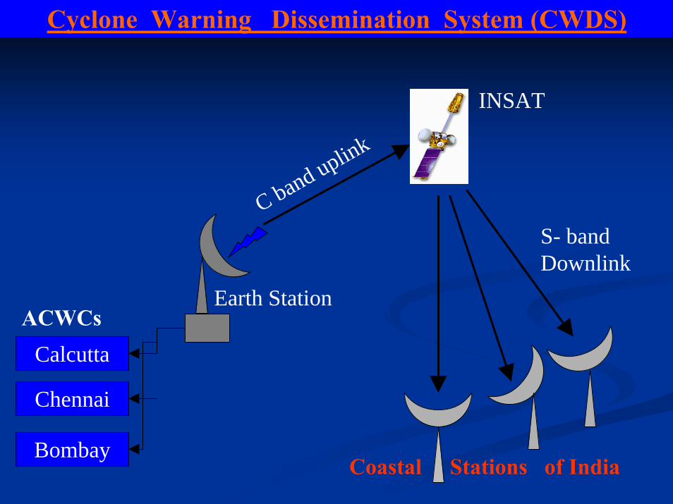
Cyclone Warning Dissemination System (CWDS)
S- band Downlink
Calcutta
BombayCoastal Stations of India
C band uplink
Earth Station
INSAT
ACWCs
Chennai
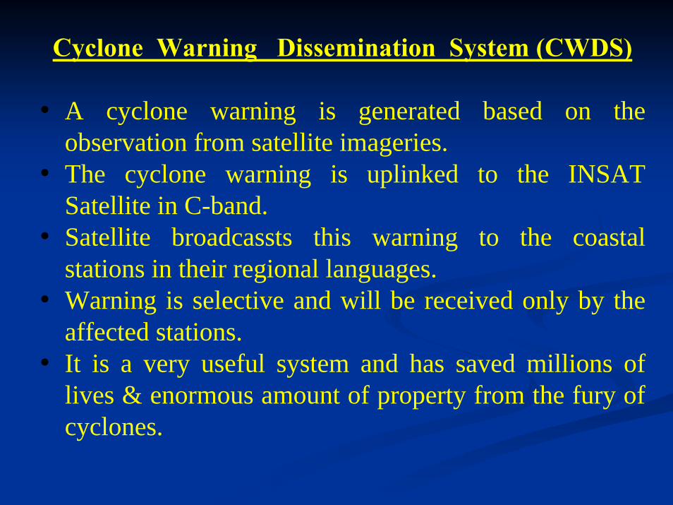
Cyclone Warning Dissemination System (CWDS)
• A cyclone warning is generated based on the observation from satellite imageries.
• The cyclone warning is uplinked to the INSAT Satellite in C-band.
• Satellite broadcassts this warning to the coastal stations in their regional languages.
• Warning is selective and will be received only by the affected stations.
• It is a very useful system and has saved millions of lives & enormous amount of property from the fury of cyclones.

For quick dissemination of warning against impending For quick dissemination of warning against impending disaster from approaching cyclones, IMD has installed disaster from approaching cyclones, IMD has installed specially designed receivers within the vulnerable coastal specially designed receivers within the vulnerable coastal areas for direct transmission of warnings to the officials areas for direct transmission of warnings to the officials and people in general using broadcast capability of INSAT and people in general using broadcast capability of INSAT satellite. satellite. IMD’s IMD’s Area Cyclone Warning Area Cyclone Warning Centres Centres (ACWC) (ACWC) generates these special warning bulletins and transmits generates these special warning bulletins and transmits them every hour in local languages to the affected areas. them every hour in local languages to the affected areas. IMD in the field areas has installed 250 such receivers. IMD in the field areas has installed 250 such receivers. CWDS has proved very effective system of warning people CWDS has proved very effective system of warning people during the cyclone affecting the coastal areas. For this during the cyclone affecting the coastal areas. For this service the frequency of transmission from ground to service the frequency of transmission from ground to satellite (uplink) is 5859.225 MHz and Downlink is at satellite (uplink) is 5859.225 MHz and Downlink is at 2559.225 MHz.2559.225 MHz.
Recently, a digital CWDS scheme has been Recently, a digital CWDS scheme has been implemented in Andhra Pradesh. One hundred digital implemented in Andhra Pradesh. One hundred digital receive stations with an uplink station at IMD, Chennai receive stations with an uplink station at IMD, Chennai have been installed. These have shown good results.have been installed. These have shown good results.

Antenna ControllerReceiver
System
A
System
B Printer
Block Diagram for HRPT System
Antenna

1.2m HRPT Tracking Antenna
TeraScan HRPT Acquisition and Processing System
Color DeskJetPrinter
HRPT Receiver
DAT Drive
Sun Ultra-10 Acquisition
and Processing
UPS
Optional Items
Antenna Pedestal
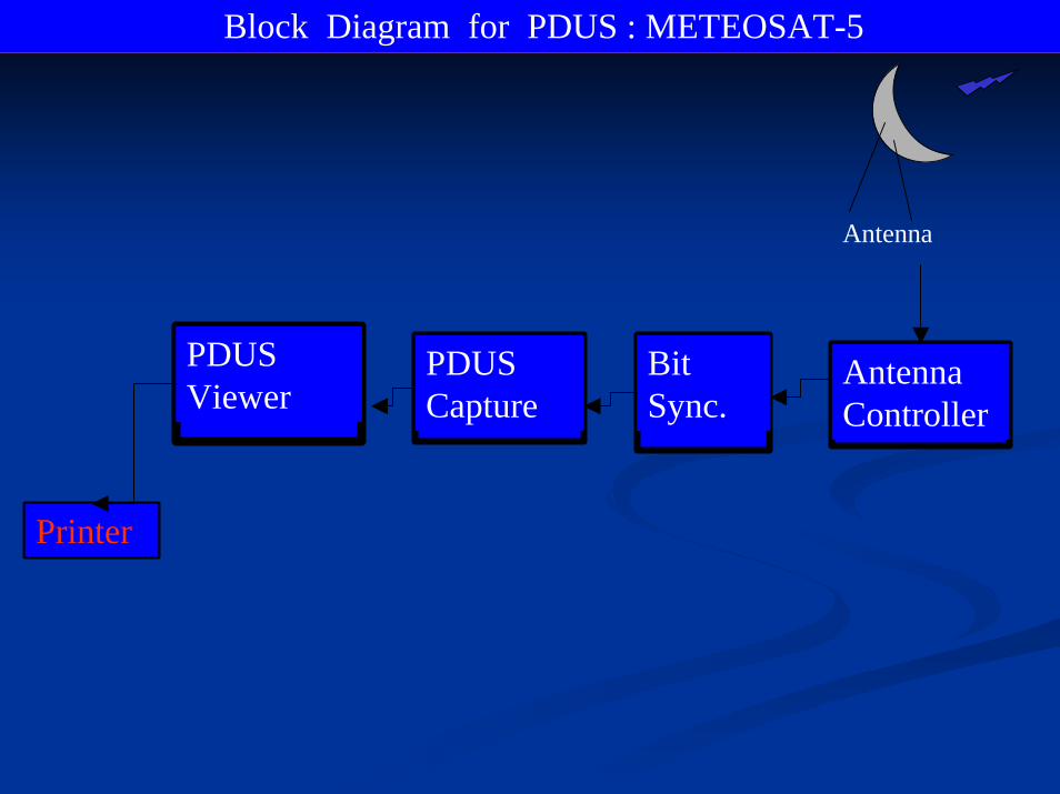
Block Diagram for PDUS : METEOSAT-5
Antenna
Printer
PDUS Viewer
PDUS Capture
Bit Sync.
Antenna Controller

Origin 3400[8p] Origin 3400[8p]
8-PortFiber Channel
Web Server A
Satellite DataNetworks
Dot Matrix Printer
BW Laser PrinterColor Laser Printer
Main Server[s][In Failsafe]
Ingest Server A
4mm DATCD-WriterDLT Drive8 mm EXABYTE
Workstation C Workstation B Workstation A
CD-WriterDLT DriveDVD RWBar Code Reader
4mm DATCD-WriterDLT Drive
4mm DATDLT Drive
2x24 port SWITCH
Tape Library Tape Library
CONSOLE A CONSOLE B
4mm DATCD-Writer8 mm EXABYTE
Ingest Server B
DLT DriveCD-Writer
Web Server B
4mm DAT
Firewall
RAID DISK ARRAY
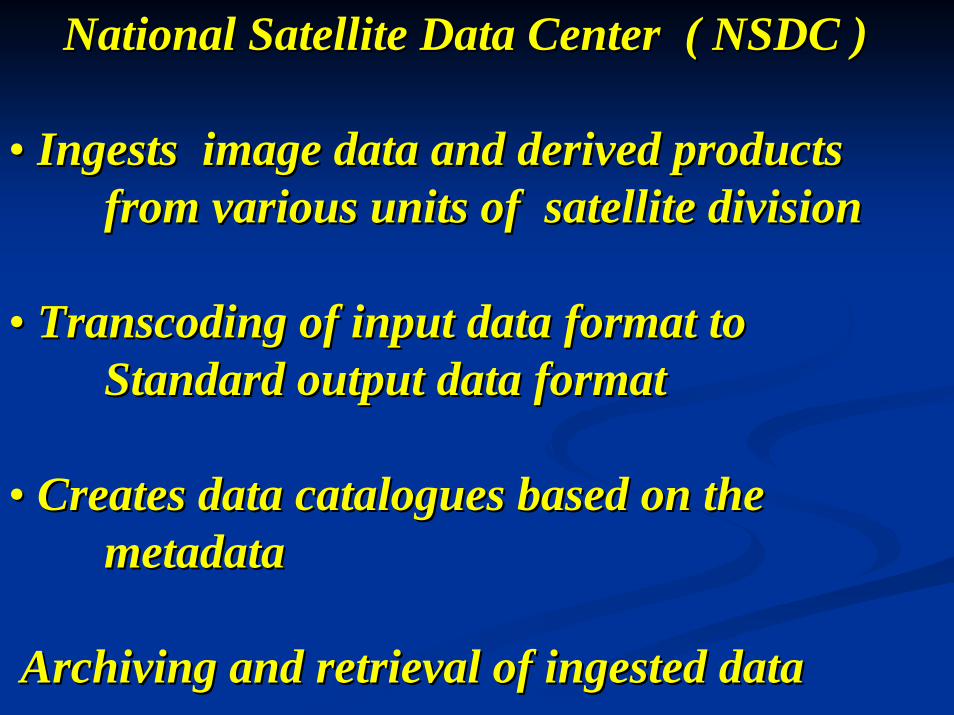
National Satellite Data Center ( NSDC )National Satellite Data Center ( NSDC )
•• Ingests image data and derived products Ingests image data and derived products from various units of satellite divisionfrom various units of satellite division
•• Transcoding Transcoding of input data format to of input data format to Standard output data formatStandard output data format
•• Creates data catalogues based on the Creates data catalogues based on the metadatametadata
Archiving and retrieval of ingested dataArchiving and retrieval of ingested data
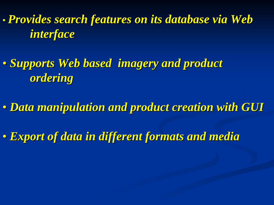
• Provides search features on its database via Web Provides search features on its database via Web interfaceinterface
•• Supports Web based imagery and product Supports Web based imagery and product orderingordering
•• Data manipulation and product creation with GUIData manipulation and product creation with GUI
•• Export of data in different formats and mediaExport of data in different formats and media


