Status of the experiment at KEKB for the hybrid targets Junji Urakawa instead of T.Takahashi KEK...
22
Status of the experiment at KEKB for the hybrid targets Junji Urakawa instead of T.Takahashi KEK Positron Workshop Durham 28 October 2009 First test of hybrid target
Transcript of Status of the experiment at KEKB for the hybrid targets Junji Urakawa instead of T.Takahashi KEK...

Status of the experiment at KEKB for the hybrid targets
Junji Urakawa instead of T.TakahashiKEK
Positron Workshop Durham28 October 2009
First test of hybrid target

R.Chehab/Posipol2008/Hiroshima, june 2008 2
POSITRON SOURCES USING CHANNELING FOR ILC & CLIC
THE BASIC SCHEME FOR ILC & CLIC
e-
Crystal Amorphous
e+, e-, e-
e+
“x” meters
Only the photons are impinging on the converter: that limits the energy deposition in the amorphous target. The yield is less than if the particles coming from the crystal were also impinging on the amorphous target
Radiator Converter

R.Chehab/Posipol2008/Hiroshima, june 2008 3
POSITRON SOURCES USING CHANNELING FOR ILC & CLIC
PROPOSED POSITRON TARGET FOR CLIC
e-
Crystal Amorphous
e+, e-, g ge-
e+
2 m
(5 GeV)
W: 1.4 mm thick W: 10 mm thick
With an incident beam of 2.34 1012 e-/pulse, we expect 2.1 1012 e+/pulse at 270 MeV (pulse of 156 ns) Or 6.7 109 e+/bunch
PEDD can bewell below damage threshold for CLIC

300Hz generation for ILC
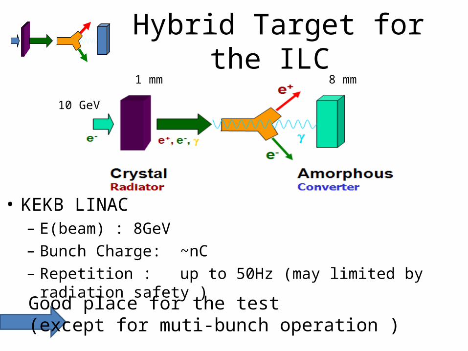
Hybrid Target for the ILC
• KEKB LINAC– E(beam) : 8GeV– Bunch Charge: ~nC– Repetition : up to 50Hz (may limited by radiation safety )
Good place for the test (except for muti-bunch operation )
10 GeV
1 mm 8 mm

experimental site KEKB LINAC
e+ source
Switch yard

Set up SiteLooking up from Down stream

A TEST at KEKB LINAC1 To Demonstrate
• positron yield with the hybrid system• heat reduction by hybrid target
2. Detail investigation toward the positron source• momentum distribution,• angular distribution of e+
w/ a real beam (angular divergence, alignment) and crystal (mosicity),,,
JFY2009
JFY2010~

Status and Preliminary results of first beam test
September 21 – 23 2009
All results shown in the following slides are preliminary

Setup
8GeV e- 1mm W crystal
Sweeping Magnet0.96T 0.75m
amorphous W0.4 mm8 mm
Analyzing magnet5 ~ 20MeV

Around the magnet
15 hole in the lead shielding
s
All charged particles aredumped here when the Sweeping magnet ON
Shielding lead bricks

Data Acquisition Counting room Beam Area
PMe+
Beam current
Gate
ADC
e-
Goniometers to Align Crystal
e+ detector
motor Controller

e+ of the least yield condition
Background conditions
Sweep mag
No Crystal
ANA. magset to 20 MeV
No Amorphous
e- Sweep mag
Crystal Woff Aligned
ANA. magset to 20 MeV
0.4mm Amorphous W
background
ADC counts
Signal is well separated from background evenwith thin converter

posi
tron
yie
ld (a
rb. u
nit)
angle of crystal w.r.t. beam (mr)
rot. in vertical plain
esweep mag
0.4mm
Rocking curve
1
2
2.27 0.06
4.86 0.2
144.4 1.1const
2 2
2 21 22 2( )f Ae Be Const
Well fitted by two Gaussians Channeling + CB?
Narrower component is still x 4wider than the critical angle

posi
tron
yie
ld (a
rb. u
nit)
angle of crystal w.r.t. beam (mr)
esweep mag
0.4mm
Rocking curve
1
2
2.07 0.04
5.3 0.2
141 1const
2 2
2 21 22 2( )f Ae Be Const
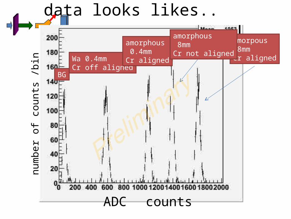
data looks likes..
BG
Wa 0.4mmCr off aligned
amorphous 0.4mmCr aligned
amorpous 8mmCr aligned
amorphous 8mmCr not aligned
ADC counts
num
ber o
f cou
nts
/bin

After BG substraction
Wa 0.4mmCr off aligned
amorphous 0.4mmCr aligned
amorpous 8mmCr aligned
amorphous 8mmCr not aligned
ADC counts
num
ber o
f cou
nts
/bin
1.9
1.2

sweeping magnet OFF
No CrystalAmorpous8mm
amorpous 8mmCr aligned
amorphous 8mmCr not aligned
ADC counts
num
ber o
f cou
nts
/bin
1.07
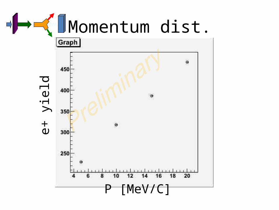
Momentum dist.
P [MeV/C]
e+ y
ield
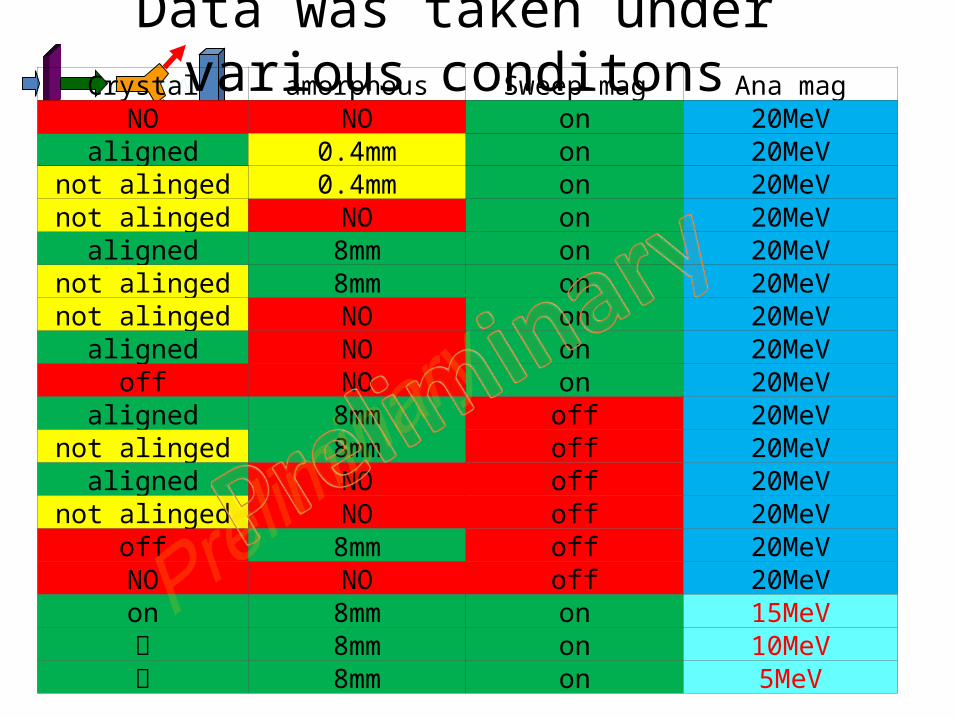
Data was taken under various conditonsCrystal amorphous Sweep mag Ana mag
NO NO on 20MeValigned 0.4mm on 20MeV
not alinged 0.4mm on 20MeVnot alinged NO on 20MeV
aligned 8mm on 20MeVnot alinged 8mm on 20MeVnot alinged NO on 20MeV
aligned NO on 20MeVoff NO on 20MeV
aligned 8mm off 20MeVnot alinged 8mm off 20MeV
aligned NO off 20MeVnot alinged NO off 20MeV
off 8mm off 20MeVNO NO off 20MeVon 8mm on 15MeV〃 8mm on 10MeV〃 8mm on 5MeV

Summray• Set up works !
– Very small backgound– DAQ seems good enough
• already have – many to be analyzed– worth to compare with simulation– some quantitative results in this workshop
• Hope temperature data in next run (Jan. 2010)
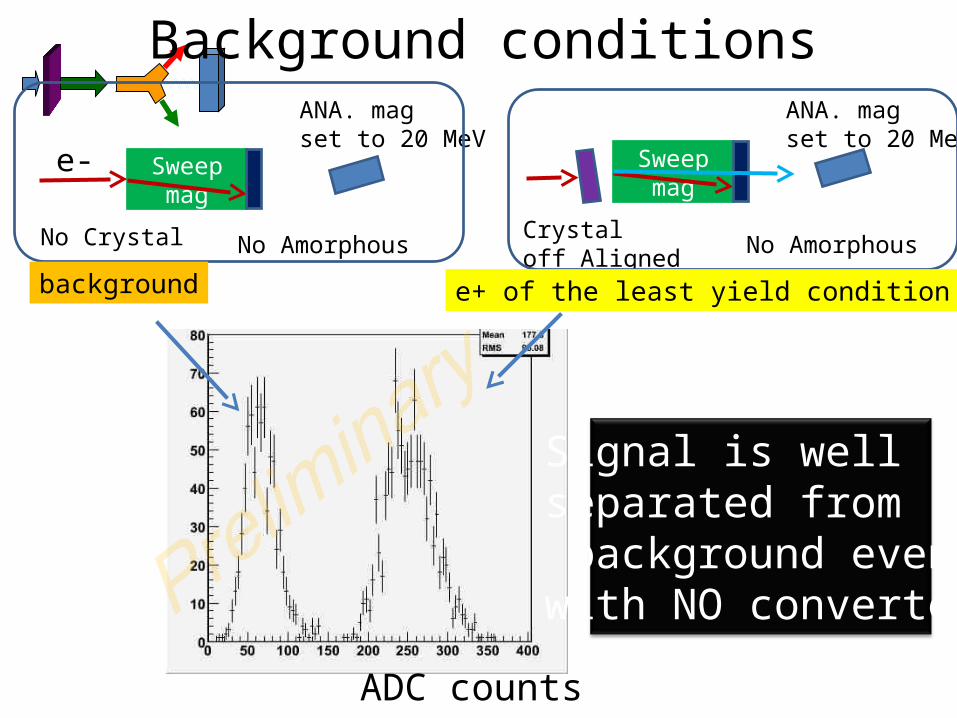
Background conditions
Sweep mag
No Crystal
ANA. magset to 20 MeV
No Amorphous
e- Sweep mag
Crystaloff Aligned
ANA. magset to 20 MeV
No Amorphous
background e+ of the least yield condition
ADC counts
Signal is well separated from background evenwith NO converter