Status of Small and Medium Sized Reactor Designs - International
Status of Small and Medium Sized Reactor Designs
A Supplement to the IAEA Advanced Reactors Information System (ARIS)
http://aris.iaea.org
Nuclear Power Technology Development Section
Division of Nuclear Power — Department of Nuclear Energy
SEPTEMBER 2011
FOREWORD
There is renewed interest in Member States in the development and application of small and medium
sized reactors (SMRs) having an equivalent electric power of less than 700 MW(e), or even less than
300 MW(e). At present, most new nuclear power plants under construction or in operation are large,
evolutionary designs with power levels of up to 1700 MW(e), building on proven systems while incorporating
technological advances. The considerable development work on small to medium sized designs generally aims
to provide increased benefits in the areas of safety and security, non-proliferation, waste management, and
resource utilization and economy, as well as to offer a variety of energy products and flexibility in design, siting
and fuel cycle options. Specifically, SMRs address deployment needs for smaller grids and lower rates of
increase in demand. They are designed with modular technology pursuing economies of series production,
factory fabrication and short construction times. The projected timelines of readiness for deployment of SMR
designs generally range from the present to 2025–2030.
The objective of this booklet is to provide Member States, including those considering initiating a nuclear
power programme and those already having practical experience in nuclear power, with a brief introduction to
the IAEA Advanced Reactors Information System (ARIS) by presenting a balanced and objective overview of
the status of small and medium sized reactor designs.
This report is intended as a supplementary booklet to ARIS, which can be accessed at http://aris.iaea.org.
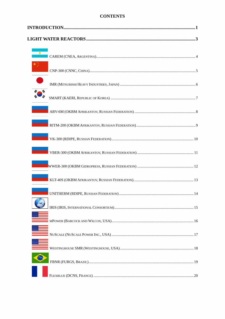
CONTENTS
INTRODUCTION.................................................................................................................... 1
LIGHT WATER REACTORS ................................................................................................ 3
CAREM (CNEA, ARGENTINA) ........................................................................................................ 4
CNP-300 (CNNC, CHINA) ............................................................................................................... 5
IMR (MITSUBISHI HEAVY INDUSTRIES, JAPAN) ............................................................................... 6
SMART (KAERI, REPUBLIC OF KOREA) ......................................................................................... 7
ABV-6M (OKBM AFRIKANTOV, RUSSIAN FEDERATION) ................................................................ 8
RITM-200 (OKBM AFRIKANTOV, RUSSIAN FEDERATION) .............................................................. 9
VK-300 (RDIPE, RUSSIAN FEDERATION) ...................................................................................... 10
VBER-300 (OKBM AFRIKANTOV, RUSSIAN FEDERATION) ........................................................... 11
WWER-300 (OKBM GIDROPRESS, RUSSIAN FEDERATION) ........................................................... 12
KLT-40S (OKBM AFRIKANTOV, RUSSIAN FEDERATION) ............................................................... 13
UNITHERM (RDIPE, RUSSIAN FEDERATION) .............................................................................. 14
IRIS (IRIS, INTERNATIONAL CONSORTIUM) ................................................................................... 15
MPOWER (BABCOCK AND WILCOX, USA) ...................................................................................... 16
NUSCALE (NUSCALE POWER INC., USA) ...................................................................................... 17
WESTINGHOUSE SMR (WESTINGHOUSE, USA) ............................................................................. 18
FBNR (FURGS, BRAZIL) .............................................................................................................. 19
FLEXBLUE (DCNS, FRANCE) ......................................................................................................... 20
HEAVY WATER REACTORS ............................................................................................. 21
EC6 (AECL, CANADA) .................................................................................................................. 22
PHWR-220 (NPCIL, INDIA) .......................................................................................................... 23
AHWR300-LEU (BARC, INDIA) .................................................................................................. 24
GAS COOLED REACTORS ................................................................................................ 25
HTR-PM (TSINGHUA UNIVERSITY, CHINA) ................................................................................... 26
PBMR (PBMR PTY, SOUTH AFRICA) ............................................................................................. 27
GT–MHR (GENERAL ATOMICS, USA) ........................................................................................... 28
EM2 (GENERAL ATOMICS, USA) .................................................................................................... 29
LIQUID METAL COOLED REACTORS .......................................................................... 30
CEFR (CNEIC, CHINA) ................................................................................................................. 31
4S (TOSHIBA, JAPAN) ..................................................................................................................... 32
PFBR-500 (IGCAR, INDIA) ........................................................................................................... 33
BREST-OD-300 (RDIPE, RUSSIAN FEDERATION) ......................................................................... 34
SVBR-100 (AKME ENGINEERING, RUSSIAN FEDERATION) ........................................................... 35
PRISM (GE-HITACHI, USA) ......................................................................................................... 36
HPM (HYPERION POWER GENERATION INC., USA) ....................................................................... 37
APPENDIX ............................................................................................................................. 38
REFERENCES ....................................................................................................................... 42
1
INTRODUCTION
The ongoing interest in the development and deployment of reactors classified as small or medium
sized is reflected in the number of small and medium sized reactors (SMRs) that operate or are under
development and the numerous innovative concepts being investigated for electricity generation and for
non-electrical applications. According to the classification adopted by the IAEA, small reactors are reactors
with an equivalent electric power of less than 300 MW(e) and medium sized reactors are reactors with an
equivalent electric power of between 300 MW(e) and 700 MW(e). Worldwide, 131 SMR units operate in 25
Member States, with a capacity of 63 GW(e). At present, 13 SMRs are under construction in six countries:
Argentina, China, India, Pakistan, the Russian Federation and Slovakia. Research is being carried out on
approximately 45 innovative SMR concepts for electricity generation and process heat production,
desalination, hydrogen generation and other applications. SRMs are under development for all principal
reactor lines, that is light water reactors (LWRs), heavy water reactors (HWRs), gas cooled reactors (GCRs)
and liquid metal cooled reactors (LMCRs).
Small and medium sized LWRs are under development in Argentina, Japan, the Republic of Korea, the
Russian Federation, the United States of America, France and Brazil. In Argentina, the Central Argentina de
Elementos Modulares (CAREM) reactor, a small, integral type pressurized LWR design with all primary
components located inside the reactor vessel and an electrical output of 150–300 MW(e), is under
development. Construction of a 27 MW(e) CAREM prototype plant is planned to begin in 2012. In Japan, a
350 MW(e) integrated modular water reactor (IMR) suitable for a hybrid heat transport system with a natural
circulation system is in the conceptual design stage. The System Integrated Modular Advanced Reactor
(SMART) design from the Republic of Korea has a thermal capacity of 330 MW(th), is intended for seawater
desalination and has almost reached the final design approval stage. In the Russian Federation, six light water
SMR designs are under development. The ABV-6M, with an electrical output of 8.6 MW(e), is a nuclear
steam generating plant with an integral pressurized light water reactor with natural circulation of the primary
coolant; it is in the detailed design stage. The RITM-200 is designed to provide 8.6 MW(e). It is an integral
reactor with forced circulation for universal nuclear icebreakers. The VK-300 is a 250 MW(e) simplified water
cooled and water moderated boiling water reactor (BWR) with natural circulation of coolant and passive
systems. The VBER-300 is a 325 MW(e) pressurized water reactor (PWR) conceptual design that can serve as
a power source for floating nuclear power plants (NPPs). In addition, the Russian Federation is building two
units of the KLT-40S series, to be mounted on a barge and used for cogeneration of process heat and
electricity. Another Russian design is the pressurized water reactor UNITHERM, which is at the conceptual
stage and is based on the N.A. Dollezhal Research and Development Institute of Power Engineering (NIKIET)
design experience in marine nuclear installations.
In the USA, three integral pressurized water SMRs are under development: Babcock and Wilcox’s
mPower, NuScale and the Westinghouse SMR. The mPower design consists of four 125 MW(e) modules, and
its design certification application is expected to be submitted in the fourth quarter of 2012. NuScale Power
envisages an NPP made up of twelve 45 MW(e) modules and plans to apply for design certification with the
US Nuclear Regulatory Commission (NRC) in 2012. The Westinghouse SMR is a conceptual design with an
electrical output of 225 MW(e) incorporating passive safety systems and proven components of the AP1000.
Another effort comes from the IRIS International Consortium, which is designing the International Reactor
Innovative and Secure (IRIS), an integral PWR design with an electrical capacity of 335 MW(e). The Fixed
Bed Nuclear Reactor (FBNR) is a Brazilian conceptual design that does not require on-site refuelling. The
Flexblue design under development in France is a small seabed NPP with an output of between 50 and
250 MW(e).
Heavy water SMRs are deployed in Argentina, Canada, China, India, the Republic of Korea, Pakistan,
and Romania. Canada has developed and deployed the Canada deuterium–uranium reactor (CANDU) series,
which offers various power ratings. The Enhanced CANDU 6 (EC6) is a basic design with a gross electrical
capacity of 740 MW(e) that is based on the CANDU 6 design. In India, several HWRs ranging in size from
220 MW(e) to 540 MW(e) to 700 MW(e) are under construction or in operation. The 304 MW(e) Advanced
Heavy Water Reactor with Low Enriched Uranium and Thorium Mixed Oxide Fuel (AHWR300-LEU) design
incorporates vertical pressure tubes, low enriched uranium and thorium fuel, and passive safety features, and is
in the basic design phase.
With regard to gas cooled reactors (GCRs), several designs in the SMR classification are under
development in China, South Africa and the USA. China has developed, constructed and deployed the
HTR-10, an experimental pebble bed helium cooled HTR. As a follow-up plant, in April 2011 China began
construction of the HTR pebble bed module (HTR-PM) consisting of two 250 MW(th) modules. In South
Africa, the Pebble Bed Modular Reactor (PBMR) conceptual design is a high temperature gas cooled reactor
(HTGR) with an electrical output of 165 MW(e). In the USA, the 150 MW(e) gas turbine modular helium
reactor is a conceptual design that has the potential to produce hydrogen by high temperature electrolysis or
thermochemical water splitting. Finally, the energy multiplier module (EM2) design is an effort to utilize used
nuclear fuel without conventional reprocessing.

2
A number of liquid metal cooled SMRs have been designed and operated in China, France, India,
Japan, the Russian Federation and the USA. The Chinese Experimental Fast Reactor (CEFR), a sodium cooled
20 MW(e) experimental fast reactor with PuO2–UO2 fuel, is currently in operation. It has reached criticality
and is in the process of being commissioned. India is building the 500 MW(e) Prototype Fast Breeder Reactor
(PFBR), which is expected to be commissioned in 2012. Japan has developed the Super Safe, Small And
Simple (4S) reactor, designed to provide 10–50 MW(e) as a very small nuclear reactor design that can be
located in a sealed, cylindrical vault underground, with the building above the ground. The Russian
Federation’s 300 MW(e) design BREST-OD-300 is a lead cooled fast reactor that uses a two circuit heat
transport system to deliver heat to a supercritical steam turbine. The Russian Federation has also developed,
and plans to construct, several SVBR-100 units, a small fast reactor with lead–bismuth eutectic alloy as the
coolant and a power output of 100 MW(e). Finally, in the USA, the Power Reactor Innovative Small Module
(PRISM), a 155 MW(e) liquid metal cooled fast breeder reactor, has been developed and an application to the
US NRC for design certification is being prepared. The Hyperion Power Module (HPM) design with an
electrical power output of 25 MW(e) is in the conceptual design stage.
LIGHT WATER REACTORS
4
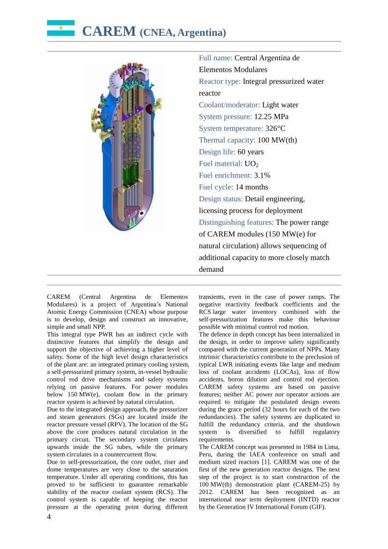
CAREM (CNEA, Argentina)
Full name: Central Argentina de
Elementos Modulares
Reactor type: Integral pressurized water
reactor
Coolant/moderator: Light water
System pressure: 12.25 MPa
System temperature: 326°C
Thermal capacity: 100 MW(th)
Design life: 60 years
Fuel material: UO2
Fuel enrichment: 3.1%
Fuel cycle: 14 months
Design status: Detail engineering,
licensing process for deployment
Distinguishing features: The power range
of CAREM modules (150 MW(e) for
natural circulation) allows sequencing of
additional capacity to more closely match
demand
CAREM (Central Argentina de Elementos
Modulares) is a project of Argentina’s National
Atomic Energy Commission (CNEA) whose purpose
is to develop, design and construct an innovative,
simple and small NPP.
This integral type PWR has an indirect cycle with
distinctive features that simplify the design and
support the objective of achieving a higher level of
safety. Some of the high level design characteristics
of the plant are: an integrated primary cooling system,
a self-pressurized primary system, in-vessel hydraulic
control rod drive mechanisms and safety systems
relying on passive features. For power modules
below 150 MW(e), coolant flow in the primary
reactor system is achieved by natural circulation.
Due to the integrated design approach, the pressurizer
and steam generators (SGs) are located inside the
reactor pressure vessel (RPV). The location of the SG
above the core produces natural circulation in the
primary circuit. The secondary system circulates
upwards inside the SG tubes, while the primary
system circulates in a countercurrent flow.
Due to self-pressurization, the core outlet, riser and
dome temperatures are very close to the saturation
temperature. Under all operating conditions, this has
proved to be sufficient to guarantee remarkable
stability of the reactor coolant system (RCS). The
control system is capable of keeping the reactor
pressure at the operating point during different
transients, even in the case of power ramps. The
negative reactivity feedback coefficients and the
RCS large water inventory combined with the
self-pressurization features make this behaviour
possible with minimal control rod motion.
The defence in depth concept has been internalized in
the design, in order to improve safety significantly
compared with the current generation of NPPs. Many
intrinsic characteristics contribute to the preclusion of
typical LWR initiating events like large and medium
loss of coolant accidents (LOCAs), loss of flow
accidents, boron dilution and control rod ejection.
CAREM safety systems are based on passive
features; neither AC power nor operator actions are
required to mitigate the postulated design events
during the grace period (32 hours for each of the two
redundancies). The safety systems are duplicated to
fulfill the redundancy criteria, and the shutdown
system is diversified to fulfill regulatory
requirements.
The CAREM concept was presented in 1984 in Lima,
Peru, during the IAEA conference on small and
medium sized reactors [1]. CAREM was one of the
first of the new generation reactor designs. The next
step of the project is to start construction of the
100 MW(th) demonstration plant (CAREM-25) by
2012. CAREM has been recognized as an
international near term deployment (INTD) reactor
by the Generation IV International Forum (GIF).
5
CNP-300 (CNNC, China)
Full name: Chinese nuclear power unit
Reactor type: Pressurized water reactor
Coolant/moderator: Light water
System pressure: 15.2 MPa
System temperature: 302°C
Thermal capacity: 999 MW(th)
Electrical capacity: 325 MW(e)
Design life: 40 years
Fuel material: UO2
Fuel enrichment: 2.4–3.0%
Fuel cycle: 12 months
Design status: In operation
Distinguishing features: Operating small
two loop PWR
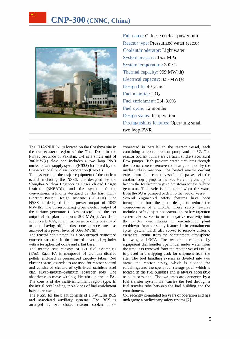
The CHASNUPP-1 is located on the Chashma site in
the northwestern region of the Thal Doab in the
Punjab province of Pakistan. C-1 is a single unit of
300 MW(e) class and includes a two loop PWR
nuclear steam supply system (NSSS) furnished by the
China National Nuclear Corporation (CNNC).
The systems and the major equipment of the nuclear
island, including the NSSS, are designed by the
Shanghai Nuclear Engineering Research and Design
Institute (SNERDI), and the system of the
conventional island is designed by the East China
Electric Power Design Institute (ECEPDI). The
NSSS is designed for a power output of 1002
MW(th). The corresponding gross electric output of
the turbine generator is 325 MW(e) and the net
output of the plant is around 300 MW(e). Accidents
such as a LOCA, steam line break or other postulated
accident having off-site dose consequences are also
analysed at a power level of 1066 MW(th).
The reactor containment is a pre-stressed reinforced
concrete structure in the form of a vertical cylinder
with a torispherical dome and a flat base.
The reactor core consists of 121 fuel assemblies
(FAs). Each FA is composed of uranium dioxide
pellets enclosed in pressurized zircaloy tubes. Rod
cluster control assemblies are used for reactor control
and consist of clusters of cylindrical stainless steel
clad silver–indium–cadmium absorber rods. The
absorber rods move within guide tubes in certain FAs.
The core is of the multi-enrichment region type. In
the initial core loading, three kinds of fuel enrichment
have been used.
The NSSS for the plant consists of a PWR, an RCS
and associated auxiliary systems. The RCS is
arranged as two closed reactor coolant loops
connected in parallel to the reactor vessel, each
containing a reactor coolant pump and an SG. The
reactor coolant pumps are vertical, single stage, axial
flow pumps. High pressure water circulates through
the reactor core to remove the heat generated by the
nuclear chain reaction. The heated reactor coolant
exits from the reactor vessel and passes via the
coolant loop piping to the SG. Here it gives up its
heat to the feedwater to generate steam for the turbine
generator. The cycle is completed when the water
from the SG is pumped back into the reactor vessel.
Several engineered safety features have been
incorporated into the plant design to reduce the
consequences of a LOCA. These safety features
include a safety injection system. The safety injection
system also serves to insert negative reactivity into
the reactor core during an uncontrolled plant
cooldown. Another safety feature is the containment
spray system which also serves to remove airborne
elemental iodine from the containment atmosphere
following a LOCA. The reactor is refuelled by
equipment that handles spent fuel under water from
the time it is removed from the reactor vessel until it
is placed in a shipping cask for shipment from the
site. The fuel handling system is divided into two
areas: the reactor cavity, which is flooded for
refuelling; and the spent fuel storage pool, which is
located in the fuel building and is always accessible
to plant personnel. The two areas are connected by a
fuel transfer system that carries the fuel through a
fuel transfer tube between the fuel building and the
containment.
C-1 recently completed ten years of operation and has
undergone a preliminary safety review [2].
6
IMR (Mitsubishi Heavy Industries, Japan)
Full name: Integrated modular water
reactor
Reactor type: Integral pressurized water
reactor
Coolant/moderator: Light water
System pressure:15.5 MPa
System temperature: 345°C
Thermal capacity: 1000 MW(th)
Electrical capacity: 350 MW(e)
Design life: 60 years
Fuel material: UO2
Fuel enrichment: 4.8%
Fuel cycle: 26 months
Design status: Conceptual design
Distinguishing features: Hybrid heat
transport system, natural circulation
system under bubbly flow conditions for
primary heat transport
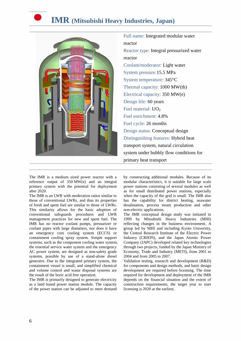
The IMR is a medium sized power reactor with a
reference output of 350 MW(e) and an integral
primary system with the potential for deployment
after 2020.
The IMR is an LWR with moderation ratios similar to
those of conventional LWRs, and thus its properties
of fresh and spent fuel are similar to those of LWRs.
This similarity allows for the basic adoption of
conventional safeguards procedures and LWR
management practices for new and spent fuel. The
IMR has no reactor coolant pumps, pressurizer or
coolant pipes with large diameters, nor does it have
an emergency core cooling system (ECCS) or
containment cooling spray system. Simple support
systems, such as the component cooling water system,
the essential service water system and the emergency
AC power system, are designed as non-safety grade
systems, possible by use of a stand-alone diesel
generator. Due to the integrated primary system, the
containment vessel is small, and simplified chemical
and volume control and waste disposal systems are
the result of the boric acid free operation.
The IMR is primarily designed to generate electricity
as a land based power station module. The capacity
of the power station can be adjusted to meet demand
by constructing additional modules. Because of its
modular characteristics, it is suitable for large scale
power stations consisting of several modules as well
as for small distributed power stations, especially
when the capacity of the grid is small. The IMR also
has the capability for district heating, seawater
desalination, process steam production and other
non-electric applications.
The IMR conceptual design study was initiated in
1999 by Mitsubishi Heavy Industries (MHI)
reflecting changes in the business environment. A
group led by MHI and including Kyoto University,
the Central Research Institute of the Electric Power
Industry (CRIEPI), and the Japan Atomic Power
Company (JAPC) developed related key technologies
through two projects, funded by the Japan Ministry of
Economy, Trade and Industry (METI), from 2001 to
2004 and from 2005 to 2007.
Validation testing, research and development (R&D)
for components and design methods, and basic design
development are required before licensing. The time
required for development and deployment of the IMR
depends on the financial situation and the extent of
construction requirements; the target year to start
licensing is 2020 at the earliest.
7
SMART (KAERI, Republic of Korea)
Full name: System integrated modular
advanced reactor
Reactor type: Integral pressurized water
reactor
Coolant/moderator: Light water
System pressure:15 MPa
System temperature: 323°C
Thermal capacity: 330 MW(th)
Electrical capacity: 100 MW(e)
Design life: 60 years
Fuel material: UO2
Fuel enrichment: 4.8%
Fuel cycle: 36 months
Design status: Seeking standard design
approval by 2011
Distinguishing features: Coupling of the
desalination system or process heat
application
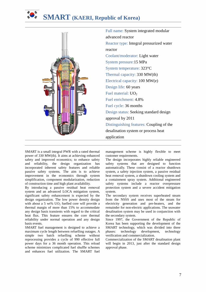
SMART is a small integral PWR with a rated thermal
power of 330 MW(th). It aims at achieving enhanced
safety and improved economics; to enhance safety
and reliability, the design organization has
incorporated inherent safety features and reliable
passive safety systems. The aim is to achieve
improvement in the economics through system
simplification, component modularization, reduction
of construction time and high plant availability.
By introducing a passive residual heat removal
system and an advanced LOCA mitigation system,
significant safety enhancement is expected by the
design organization. The low power density design
with about a 5 wt% UO2 fuelled core will provide a
thermal margin of more than 15% to accommodate
any design basis transients with regard to the critical
heat flux. This feature ensures the core thermal
reliability under normal operation and any design
basis events.
SMART fuel management is designed to achieve a
maximum cycle length between refuelling outages. A
simple two batch refuelling scheme without
reprocessing provides a cycle of 990 effective full
power days for a 36 month operation. This reload
scheme minimizes complicated fuel shuffle schemes
and enhances fuel utilization. The SMART fuel
management scheme is highly flexible to meet
customer requirements.
The design incorporates highly reliable engineered
safety systems that are designed to function
automatically. These consist of a reactor shutdown
system, a safety injection system, a passive residual
heat removal system, a shutdown cooling system and
a containment spray system. Additional engineered
safety systems include a reactor overpressure
protection system and a severe accident mitigation
system.
The secondary system receives superheated steam
from the NSSS and uses most of the steam for
electricity generation and pre-heaters, and the
remainder for non-electric applications. The seawater
desalination system may be used in conjunction with
the secondary system.
Since 1997, the Government of the Republic of
Korea has been supporting the development of the
SMART technology, which was divided into three
phases: technology development, technology
verification and commercialization.
Commercialization of the SMART desalination plant
will begin in 2013, just after the standard design
approval phase.
8
ABV-6M (OKBM Afrikantov, Russian Federation)
Reactor type: Pressurized light water
reactor
Coolant/moderator: Light water
System pressure: 15.7 MPa
System temperature: 330°C
Thermal capacity: 38 MW(th)
Electrical capacity: 8.6 MW(e)
Design life: 60 years
Fuel material: UO2
Fuel enrichment: 19.7%
Reactor core life: 10 years
Design status: Detailed design
Distinguishing features: Natural
circulation in the primary circuit for land
based and floating nuclear power plants
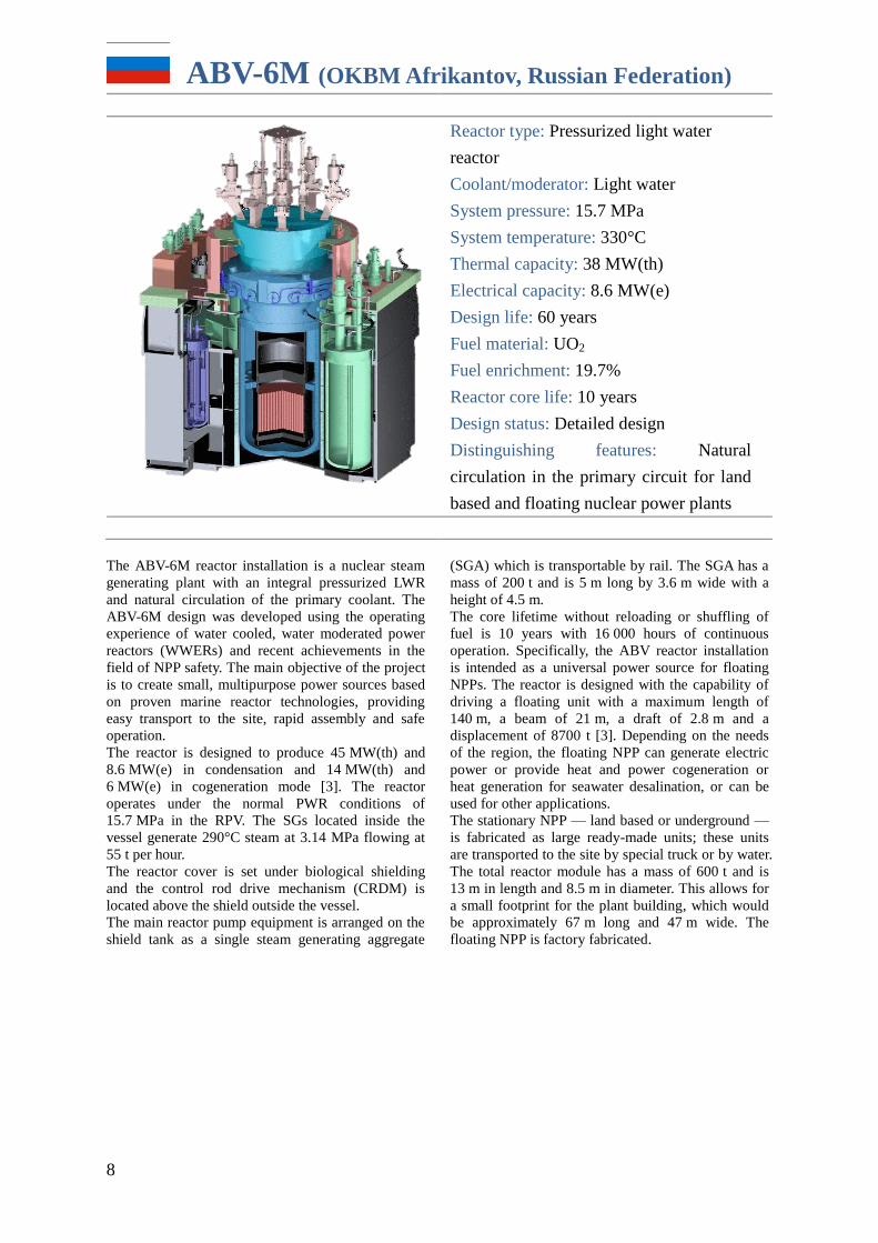
The ABV-6M reactor installation is a nuclear steam
generating plant with an integral pressurized LWR
and natural circulation of the primary coolant. The
ABV-6M design was developed using the operating
experience of water cooled, water moderated power
reactors (WWERs) and recent achievements in the
field of NPP safety. The main objective of the project
is to create small, multipurpose power sources based
on proven marine reactor technologies, providing
easy transport to the site, rapid assembly and safe
operation.
The reactor is designed to produce 45 MW(th) and
8.6 MW(e) in condensation and 14 MW(th) and
6 MW(e) in cogeneration mode [3]. The reactor
operates under the normal PWR conditions of
15.7 MPa in the RPV. The SGs located inside the
vessel generate 290°C steam at 3.14 MPa flowing at
55 t per hour.
The reactor cover is set under biological shielding
and the control rod drive mechanism (CRDM) is
located above the shield outside the vessel.
The main reactor pump equipment is arranged on the
shield tank as a single steam generating aggregate
(SGA) which is transportable by rail. The SGA has a
mass of 200 t and is 5 m long by 3.6 m wide with a
height of 4.5 m.
The core lifetime without reloading or shuffling of
fuel is 10 years with 16 000 hours of continuous
operation. Specifically, the ABV reactor installation
is intended as a universal power source for floating
NPPs. The reactor is designed with the capability of
driving a floating unit with a maximum length of
140 m, a beam of 21 m, a draft of 2.8 m and a
displacement of 8700 t [3]. Depending on the needs
of the region, the floating NPP can generate electric
power or provide heat and power cogeneration or
heat generation for seawater desalination, or can be
used for other applications.
The stationary NPP — land based or underground —
is fabricated as large ready-made units; these units
are transported to the site by special truck or by water.
The total reactor module has a mass of 600 t and is
13 m in length and 8.5 m in diameter. This allows for
a small footprint for the plant building, which would
be approximately 67 m long and 47 m wide. The
floating NPP is factory fabricated.
9
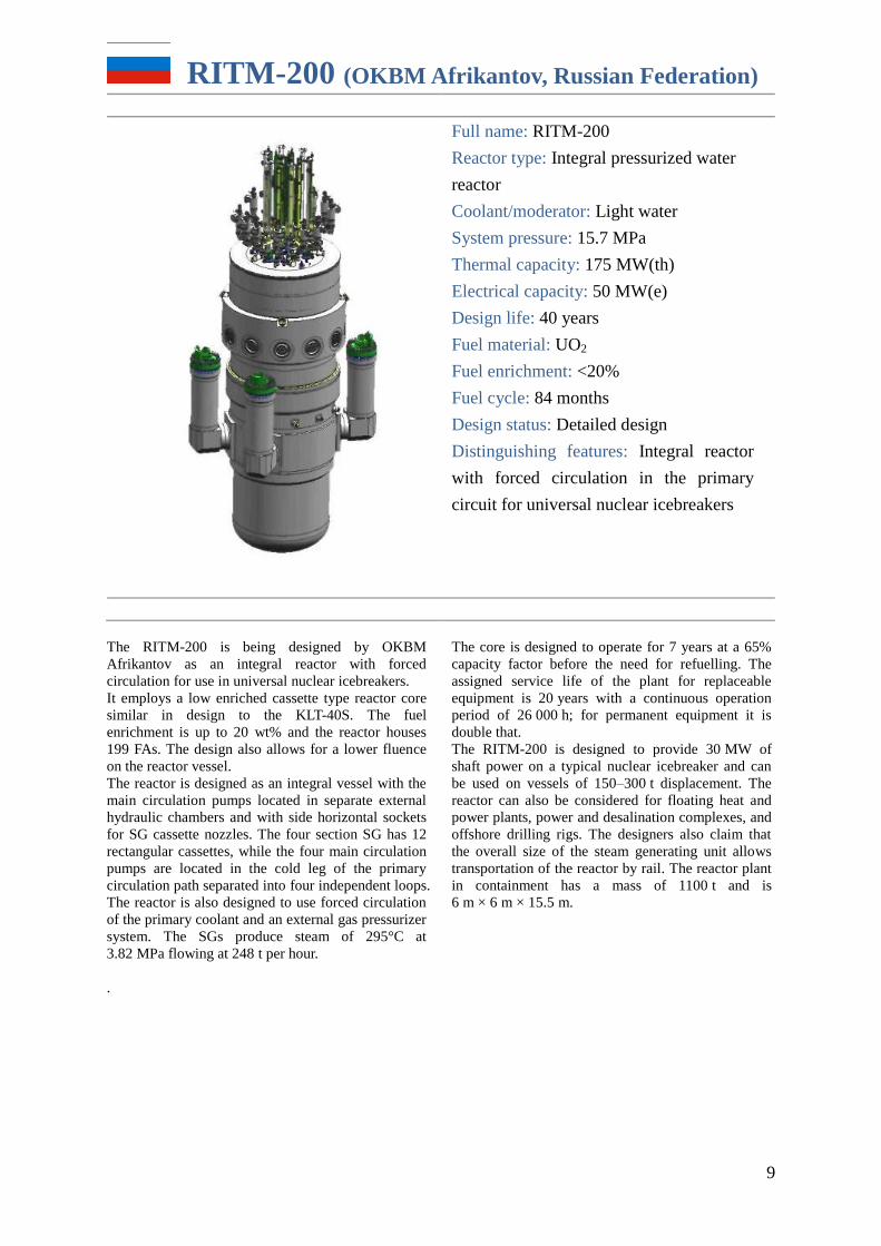
RITM-200 (OKBM Afrikantov, Russian Federation)
Full name: RITM-200
Reactor type: Integral pressurized water
reactor
Coolant/moderator: Light water
System pressure: 15.7 MPa
Thermal capacity: 175 MW(th)
Electrical capacity: 50 MW(e)
Design life: 40 years
Fuel material: UO2
Fuel enrichment: <20%
Fuel cycle: 84 months
Design status: Detailed design
Distinguishing features: Integral reactor
with forced circulation in the primary
circuit for universal nuclear icebreakers
The RITM-200 is being designed by OKBM
Afrikantov as an integral reactor with forced
circulation for use in universal nuclear icebreakers.
It employs a low enriched cassette type reactor core
similar in design to the KLT-40S. The fuel
enrichment is up to 20 wt% and the reactor houses
199 FAs. The design also allows for a lower fluence
on the reactor vessel.
The reactor is designed as an integral vessel with the
main circulation pumps located in separate external
hydraulic chambers and with side horizontal sockets
for SG cassette nozzles. The four section SG has 12
rectangular cassettes, while the four main circulation
pumps are located in the cold leg of the primary
circulation path separated into four independent loops.
The reactor is also designed to use forced circulation
of the primary coolant and an external gas pressurizer
system. The SGs produce steam of 295°C at
3.82 MPa flowing at 248 t per hour.
The core is designed to operate for 7 years at a 65%
capacity factor before the need for refuelling. The
assigned service life of the plant for replaceable
equipment is 20 years with a continuous operation
period of 26 000 h; for permanent equipment it is
double that.
The RITM-200 is designed to provide 30 MW of
shaft power on a typical nuclear icebreaker and can
be used on vessels of 150–300 t displacement. The
reactor can also be considered for floating heat and
power plants, power and desalination complexes, and
offshore drilling rigs. The designers also claim that
the overall size of the steam generating unit allows
transportation of the reactor by rail. The reactor plant
in containment has a mass of 1100 t and is
6 m × 6 m × 15.5 m.
.
10
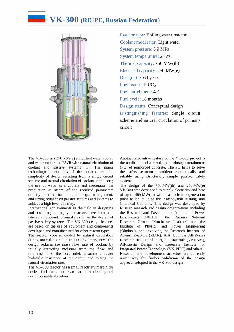
VK-300 (RDIPE, Russian Federation)
Reactor type: Boiling water reactor
Coolant/moderator: Light water
System pressure: 6.9 MPa
System temperature: 285°C
Thermal capacity: 750 MW(th)
Electrical capacity: 250 MW(e)
Design life: 60 years
Fuel material: UO2
Fuel enrichment: 4%
Fuel cycle: 18 months
Design status: Conceptual design
Distinguishing features: Single circuit
scheme and natural circulation of primary
circuit
The VK-300 is a 250 MW(e) simplified water cooled
and water moderated BWR with natural circulation of
coolant and passive systems [1]. The major
technological principles of the concept are: the
simplicity of design resulting from a single circuit
scheme and natural circulation of coolant in the core;
the use of water as a coolant and moderator; the
production of steam of the required parameters
directly in the reactor due to an integral arrangement;
and strong reliance on passive features and systems to
achieve a high level of safety.
International achievements in the field of designing
and operating boiling type reactors have been also
taken into account, primarily as far as the design of
passive safety systems. The VK-300 design features
are based on the use of equipment and components
developed and manufactured for other reactor types.
The reactor core is cooled by natural circulation
during normal operation and in any emergency. The
design reduces the mass flow rate of coolant by
initially extracting moisture from the flow and
returning it to the core inlet, ensuring a lower
hydraulic resistance of the circuit and raising the
natural circulation rate.
The VK-300 reactor has a small reactivity margin for
nuclear fuel burnup thanks to partial overloading and
use of burnable absorbers.
Another innovative feature of the VK-300 project is
the application of a metal lined primary containment
(PC) of reinforced concrete. The PC helps to solve
the safety assurance problem economically and
reliably using structurally simple passive safety
systems.
The design of the 750 MW(th) and 250 MW(e)
VK-300 was developed to supply electricity and heat
of up to 465 MW(th) within a nuclear cogeneration
plant to be built at the Krasnoyarsk Mining and
Chemical Combine. This design was developed by
Russian research and design organizations including
the Research and Development Institute of Power
Engineering (NIKIET), the Russian National
Research Centre ‘Kurchatov Institute’ and the
Institute of Physics and Power Engineering
(Obninsk), and involving the Research Institute of
Atomic Reactors (RIAR), A.A. Bochvar All-Russia
Research Institute of Inorganic Materials (VNIINM),
All-Russia Design and Research Institute for
Integrated Power Technology (VNIPIET) and others.
Research and development activities are currently
under way for further validation of the design
approach adopted in the VK-300 design.
11
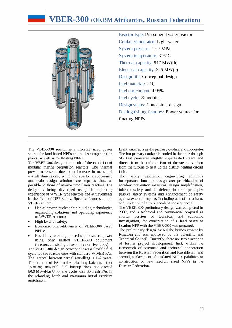
VBER-300 (OKBM Afrikantov, Russian Federation)
Reactor type: Pressurized water reactor
Coolant/moderator: Light water
System pressure: 12.7 MPa
System temperature: 316°C
Thermal capacity: 917 MW(th)
Electrical capacity: 325 MW(e)
Design life: Conceptual design
Fuel material: UO2
Fuel enrichment: 4.95%
Fuel cycle: 72 months
Design status: Conceptual design
Distinguishing features: Power source for
floating NPPs
The VBER-300 reactor is a medium sized power
source for land based NPPs and nuclear cogeneration
plants, as well as for floating NPPs.
The VBER-300 design is a result of the evolution of
modular marine propulsion reactors. The thermal
power increase is due to an increase in mass and
overall dimensions, while the reactor’s appearance
and main design solutions are kept as close as
possible to those of marine propulsion reactors. The
design is being developed using the operating
experience of WWER type reactors and achievements
in the field of NPP safety. Specific features of the
VBER-300 are:
Use of proven nuclear ship building technologies,
engineering solutions and operating experience
of WWER reactors;
High level of safety;
Economic competitiveness of VBER-300 based
NPPs;
Possibility to enlarge or reduce the source power
using only unified VBER-300 equipment
(reactors consisting of two, three or five loops).
The VBER-300 design concept allows a flexible fuel
cycle for the reactor core with standard WWER FAs.
The interval between partial refuelling is 1–2 years.
The number of FAs in the refuelling batch is either
15 or 30; maximal fuel burnup does not exceed
60.0 MW∙d/kg U for the cycle with 30 fresh FAs in
the reloading batch and maximum initial uranium
enrichment.
Light water acts as the primary coolant and moderator.
The hot primary coolant is cooled in the once through
SG that generates slightly superheated steam and
directs it to the turbine. Part of the steam is taken
from the turbine to heat up the district heating circuit
fluid.
The safety assurance engineering solutions
incorporated into the design are: prioritization of
accident prevention measures, design simplification,
inherent safety, and the defence in depth principle;
passive safety systems and enhancement of safety
against external impacts (including acts of terrorism);
and limitation of severe accident consequences.
The VBER-300 preliminary design was completed in
2002, and a technical and commercial proposal (a
shorter version of technical and economic
investigation) for construction of a land based or
floating NPP with the VBER-300 was prepared.
The preliminary design passed the branch review by
Rosatom and was approved by the Scientific and
Technical Council. Currently, there are two directions
of further project development: first, within the
framework of scientific and technical cooperation
between the Russian Federation and Kazakhstan; and
second, replacement of outdated NPP capabilities or
construction of new medium sized NPPs in the
Russian Federation.
12
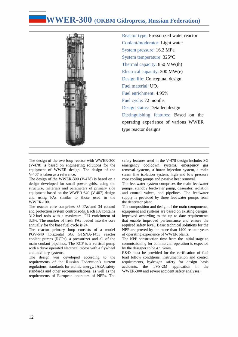
WWER-300 (OKBM Gidropress, Russian Federation)
Reactor type: Pressurized water reactor
Coolant/moderator: Light water
System pressure: 16.2 MPa
System temperature: 325°C
Thermal capacity: 850 MW(th)
Electrical capacity: 300 MW(e)
Design life: Conceptual design
Fuel material: UO2
Fuel enrichment: 4.95%
Fuel cycle: 72 months
Design status: Detailed design
Distinguishing features: Based on the
operating experience of various WWER
type reactor designs
The design of the two loop reactor with WWER-300
(V-478) is based on engineering solutions for the
equipment of WWER design. The design of the
V-407 is taken as a reference.
The design of the WWER-300 (V-478) is based on a
design developed for small power grids, using the
structure, materials and parameters of primary side
equipment based on the WWER-640 (V-407) design
and using FAs similar to those used in the
WWER-100.
The reactor core comprises 85 FAs and 34 control
and protection system control rods. Each FA contains
312 fuel rods with a maximum 235
U enrichment of
3.3%. The number of fresh FAs loaded into the core
annually for the base fuel cycle is 24.
The reactor primary loop consists of a model
PGV-640 horizontal SG, GTSNA-1455 reactor
coolant pumps (RCPs), a pressurizer and all of the
main coolant pipelines. The RCP is a vertical pump
with a drive operated electrical motor with a flywheel
and auxiliary systems.
The design was developed according to the
requirements of the Russian Federation’s current
regulations, standards for atomic energy, IAEA safety
standards and other recommendations, as well as the
requirements of European operators of NPPs. The
safety features used in the V-478 design include: SG
emergency cooldown systems, emergency gas
removal systems, a boron injection system, a main
steam line isolation system, high and low pressure
core cooling pumps and passive heat removal.
The feedwater system comprises the main feedwater
pumps, standby feedwater pump, deaerator, isolation
and control valves, and pipelines. The feedwater
supply is provided by three feedwater pumps from
the deaerator plant.
The composition and design of the main components,
equipment and systems are based on existing designs,
improved according to the up to date requirements
that enable improved performance and ensure the
required safety level. Basic technical solutions for the
NPP are proved by the more than 1400 reactor-years
of operating experience of WWER plants.
The NPP construction time from the initial stage to
commissioning for commercial operation is expected
by the designer to be 4.5 years.
R&D must be provided for the verification of fuel
load follow conditions, instrumentation and control
requirements, hydrogen safety for design basis
accidents, the TVS-2M application in the
WWER-300 and severe accident safety analyses.
13
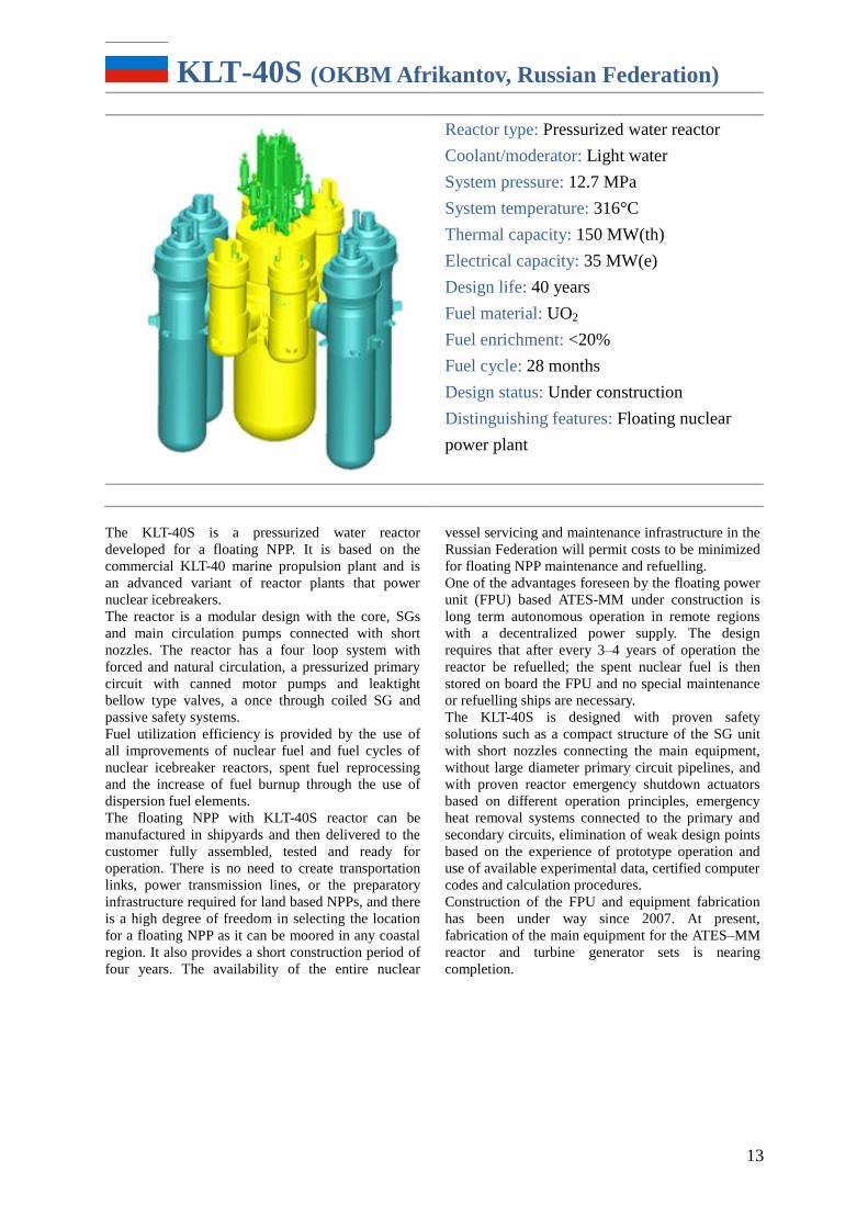
KLT-40S (OKBM Afrikantov, Russian Federation)
Reactor type: Pressurized water reactor
Coolant/moderator: Light water
System pressure: 12.7 MPa
System temperature: 316°C
Thermal capacity: 150 MW(th)
Electrical capacity: 35 MW(e)
Design life: 40 years
Fuel material: UO2
Fuel enrichment: <20%
Fuel cycle: 28 months
Design status: Under construction
Distinguishing features: Floating nuclear
power plant
The KLT-40S is a pressurized water reactor
developed for a floating NPP. It is based on the
commercial KLT-40 marine propulsion plant and is
an advanced variant of reactor plants that power
nuclear icebreakers.
The reactor is a modular design with the core, SGs
and main circulation pumps connected with short
nozzles. The reactor has a four loop system with
forced and natural circulation, a pressurized primary
circuit with canned motor pumps and leaktight
bellow type valves, a once through coiled SG and
passive safety systems.
Fuel utilization efficiency is provided by the use of
all improvements of nuclear fuel and fuel cycles of
nuclear icebreaker reactors, spent fuel reprocessing
and the increase of fuel burnup through the use of
dispersion fuel elements.
The floating NPP with KLT-40S reactor can be
manufactured in shipyards and then delivered to the
customer fully assembled, tested and ready for
operation. There is no need to create transportation
links, power transmission lines, or the preparatory
infrastructure required for land based NPPs, and there
is a high degree of freedom in selecting the location
for a floating NPP as it can be moored in any coastal
region. It also provides a short construction period of
four years. The availability of the entire nuclear
vessel servicing and maintenance infrastructure in the
Russian Federation will permit costs to be minimized
for floating NPP maintenance and refuelling.
One of the advantages foreseen by the floating power
unit (FPU) based ATES-MM under construction is
long term autonomous operation in remote regions
with a decentralized power supply. The design
requires that after every 3–4 years of operation the
reactor be refuelled; the spent nuclear fuel is then
stored on board the FPU and no special maintenance
or refuelling ships are necessary.
The KLT-40S is designed with proven safety
solutions such as a compact structure of the SG unit
with short nozzles connecting the main equipment,
without large diameter primary circuit pipelines, and
with proven reactor emergency shutdown actuators
based on different operation principles, emergency
heat removal systems connected to the primary and
secondary circuits, elimination of weak design points
based on the experience of prototype operation and
use of available experimental data, certified computer
codes and calculation procedures.
Construction of the FPU and equipment fabrication
has been under way since 2007. At present,
fabrication of the main equipment for the ATES–MM
reactor and turbine generator sets is nearing
completion.
14
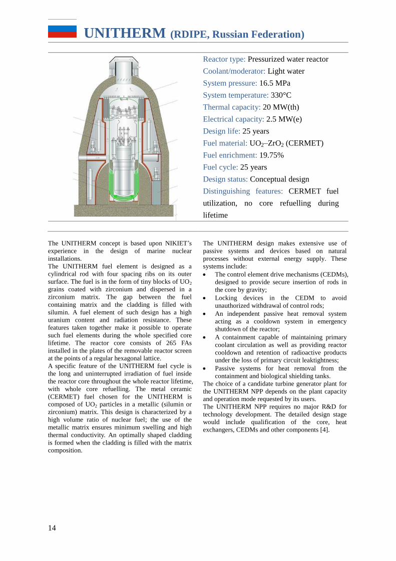
UNITHERM (RDIPE, Russian Federation)
Reactor type: Pressurized water reactor
Coolant/moderator: Light water
System pressure: 16.5 MPa
System temperature: 330°C
Thermal capacity: 20 MW(th)
Electrical capacity: 2.5 MW(e)
Design life: 25 years
Fuel material: UO2–ZrO2 (CERMET)
Fuel enrichment: 19.75%
Fuel cycle: 25 years
Design status: Conceptual design
Distinguishing features: CERMET fuel
utilization, no core refuelling during
lifetime
The UNITHERM concept is based upon NIKIET’s
experience in the design of marine nuclear
installations.
The UNITHERM fuel element is designed as a
cylindrical rod with four spacing ribs on its outer
surface. The fuel is in the form of tiny blocks of UO2
grains coated with zirconium and dispersed in a
zirconium matrix. The gap between the fuel
containing matrix and the cladding is filled with
silumin. A fuel element of such design has a high
uranium content and radiation resistance. These
features taken together make it possible to operate
such fuel elements during the whole specified core
lifetime. The reactor core consists of 265 FAs
installed in the plates of the removable reactor screen
at the points of a regular hexagonal lattice.
A specific feature of the UNITHERM fuel cycle is
the long and uninterrupted irradiation of fuel inside
the reactor core throughout the whole reactor lifetime,
with whole core refuelling. The metal ceramic
(CERMET) fuel chosen for the UNITHERM is
composed of UO2 particles in a metallic (silumin or
zirconium) matrix. This design is characterized by a
high volume ratio of nuclear fuel; the use of the
metallic matrix ensures minimum swelling and high
thermal conductivity. An optimally shaped cladding
is formed when the cladding is filled with the matrix
composition.
The UNITHERM design makes extensive use of
passive systems and devices based on natural
processes without external energy supply. These
systems include:
The control element drive mechanisms (CEDMs),
designed to provide secure insertion of rods in
the core by gravity;
Locking devices in the CEDM to avoid
unauthorized withdrawal of control rods;
An independent passive heat removal system
acting as a cooldown system in emergency
shutdown of the reactor;
A containment capable of maintaining primary
coolant circulation as well as providing reactor
cooldown and retention of radioactive products
under the loss of primary circuit leaktightness;
Passive systems for heat removal from the
containment and biological shielding tanks.
The choice of a candidate turbine generator plant for
the UNITHERM NPP depends on the plant capacity
and operation mode requested by its users.
The UNITHERM NPP requires no major R&D for
technology development. The detailed design stage
would include qualification of the core, heat
exchangers, CEDMs and other components [4].
15
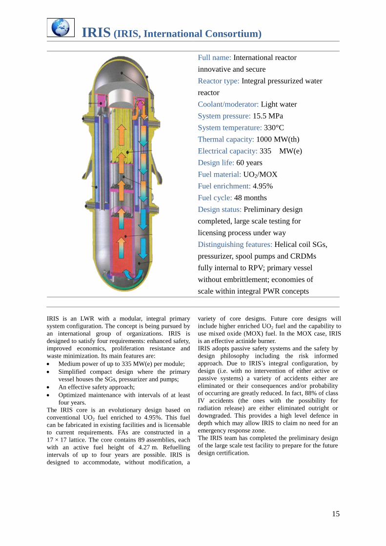
IRIS (IRIS, International Consortium)
Full name: International reactor
innovative and secure
Reactor type: Integral pressurized water
reactor
Coolant/moderator: Light water
System pressure: 15.5 MPa
System temperature: 330°C
Thermal capacity: 1000 MW(th)
Electrical capacity: 335 MW(e)
Design life: 60 years
Fuel material: UO2/MOX
Fuel enrichment: 4.95%
Fuel cycle: 48 months
Design status: Preliminary design
completed, large scale testing for
licensing process under way
Distinguishing features: Helical coil SGs,
pressurizer, spool pumps and CRDMs
fully internal to RPV; primary vessel
without embrittlement; economies of
scale within integral PWR concepts
IRIS is an LWR with a modular, integral primary
system configuration. The concept is being pursued by
an international group of organizations. IRIS is
designed to satisfy four requirements: enhanced safety,
improved economics, proliferation resistance and
waste minimization. Its main features are:
Medium power of up to 335 MW(e) per module;
Simplified compact design where the primary
vessel houses the SGs, pressurizer and pumps;
An effective safety approach;
Optimized maintenance with intervals of at least
four years.
The IRIS core is an evolutionary design based on
conventional UO2 fuel enriched to 4.95%. This fuel
can be fabricated in existing facilities and is licensable
to current requirements. FAs are constructed in a
17 × 17 lattice. The core contains 89 assemblies, each
with an active fuel height of 4.27 m. Refuelling
intervals of up to four years are possible. IRIS is
designed to accommodate, without modification, a
variety of core designs. Future core designs will
include higher enriched UO2 fuel and the capability to
use mixed oxide (MOX) fuel. In the MOX case, IRIS
is an effective actinide burner.
IRIS adopts passive safety systems and the safety by
design philosophy including the risk informed
approach. Due to IRIS’s integral configuration, by
design (i.e. with no intervention of either active or
passive systems) a variety of accidents either are
eliminated or their consequences and/or probability
of occurring are greatly reduced. In fact, 88% of class
IV accidents (the ones with the possibility for
radiation release) are either eliminated outright or
downgraded. This provides a high level defence in
depth which may allow IRIS to claim no need for an
emergency response zone.
The IRIS team has completed the preliminary design
of the large scale test facility to prepare for the future
design certification.
16
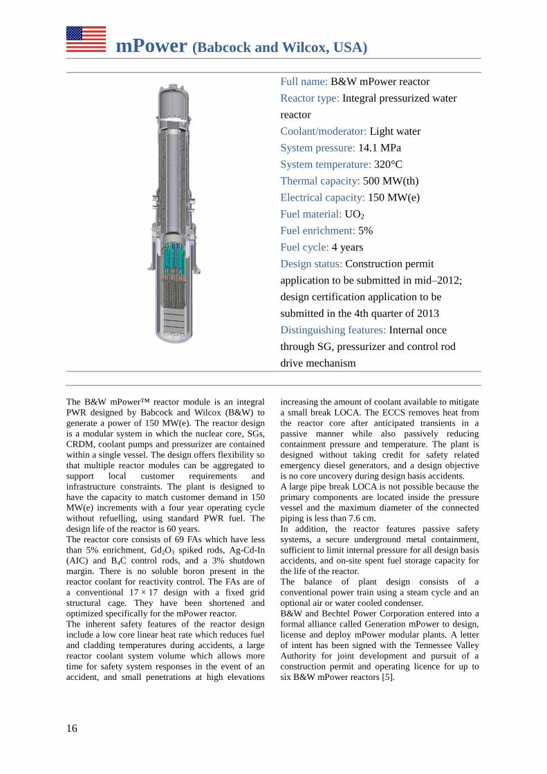
mPower (Babcock and Wilcox, USA)
Full name: B&W mPower reactor
Reactor type: Integral pressurized water
reactor
Coolant/moderator: Light water
System pressure: 14.1 MPa
System temperature: 320°C
Thermal capacity: 500 MW(th)
Electrical capacity: 150 MW(e)
Fuel material: UO2
Fuel enrichment: 5%
Fuel cycle: 4 years
Design status: Construction permit
application to be submitted in mid–2012;
design certification application to be
submitted in the 4th quarter of 2013
Distinguishing features: Internal once
through SG, pressurizer and control rod
drive mechanism
The B&W mPower™ reactor module is an integral
PWR designed by Babcock and Wilcox (B&W) to
generate a power of 150 MW(e). The reactor design
is a modular system in which the nuclear core, SGs,
CRDM, coolant pumps and pressurizer are contained
within a single vessel. The design offers flexibility so
that multiple reactor modules can be aggregated to
support local customer requirements and
infrastructure constraints. The plant is designed to
have the capacity to match customer demand in 150
MW(e) increments with a four year operating cycle
without refuelling, using standard PWR fuel. The
design life of the reactor is 60 years.
The reactor core consists of 69 FAs which have less
than 5% enrichment, Gd2O3 spiked rods, Ag-Cd-In
(AIC) and B4C control rods, and a 3% shutdown
margin. There is no soluble boron present in the
reactor coolant for reactivity control. The FAs are of
a conventional 17 × 17 design with a fixed grid
structural cage. They have been shortened and
optimized specifically for the mPower reactor.
The inherent safety features of the reactor design
include a low core linear heat rate which reduces fuel
and cladding temperatures during accidents, a large
reactor coolant system volume which allows more
time for safety system responses in the event of an
accident, and small penetrations at high elevations
increasing the amount of coolant available to mitigate
a small break LOCA. The ECCS removes heat from
the reactor core after anticipated transients in a
passive manner while also passively reducing
containment pressure and temperature. The plant is
designed without taking credit for safety related
emergency diesel generators, and a design objective
is no core uncovery during design basis accidents.
A large pipe break LOCA is not possible because the
primary components are located inside the pressure
vessel and the maximum diameter of the connected
piping is less than 7.6 cm.
In addition, the reactor features passive safety
systems, a secure underground metal containment,
sufficient to limit internal pressure for all design basis
accidents, and on-site spent fuel storage capacity for
the life of the reactor.
The balance of plant design consists of a
conventional power train using a steam cycle and an
optional air or water cooled condenser.
B&W and Bechtel Power Corporation entered into a
formal alliance called Generation mPower to design,
license and deploy mPower modular plants. A letter
of intent has been signed with the Tennessee Valley
Authority for joint development and pursuit of a
construction permit and operating licence for up to
six B&W mPower reactors [5].
17
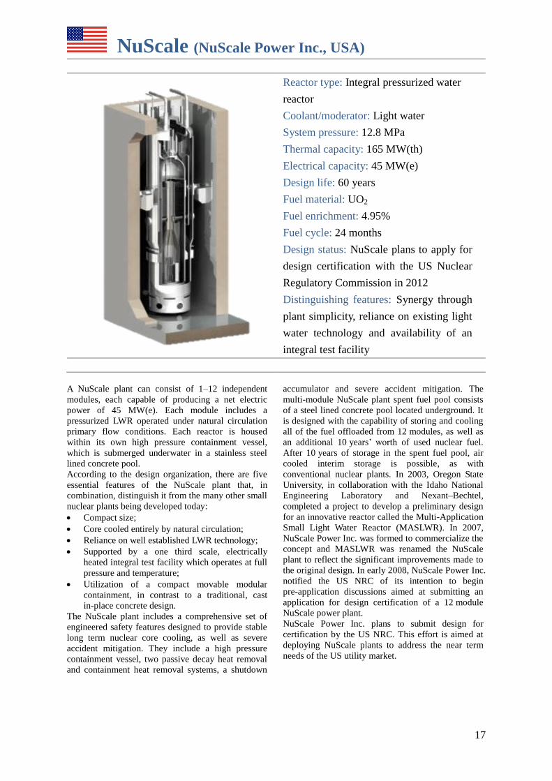
NuScale (NuScale Power Inc., USA)
Reactor type: Integral pressurized water
reactor
Coolant/moderator: Light water
System pressure: 12.8 MPa
Thermal capacity: 165 MW(th)
Electrical capacity: 45 MW(e)
Design life: 60 years
Fuel material: UO2
Fuel enrichment: 4.95%
Fuel cycle: 24 months
Design status: NuScale plans to apply for
design certification with the US Nuclear
Regulatory Commission in 2012
Distinguishing features: Synergy through
plant simplicity, reliance on existing light
water technology and availability of an
integral test facility
A NuScale plant can consist of 1–12 independent
modules, each capable of producing a net electric
power of 45 MW(e). Each module includes a
pressurized LWR operated under natural circulation
primary flow conditions. Each reactor is housed
within its own high pressure containment vessel,
which is submerged underwater in a stainless steel
lined concrete pool.
According to the design organization, there are five
essential features of the NuScale plant that, in
combination, distinguish it from the many other small
nuclear plants being developed today:
Compact size;
Core cooled entirely by natural circulation;
Reliance on well established LWR technology;
Supported by a one third scale, electrically
heated integral test facility which operates at full
pressure and temperature;
Utilization of a compact movable modular
containment, in contrast to a traditional, cast
in-place concrete design.
The NuScale plant includes a comprehensive set of
engineered safety features designed to provide stable
long term nuclear core cooling, as well as severe
accident mitigation. They include a high pressure
containment vessel, two passive decay heat removal
and containment heat removal systems, a shutdown
accumulator and severe accident mitigation. The
multi-module NuScale plant spent fuel pool consists
of a steel lined concrete pool located underground. It
is designed with the capability of storing and cooling
all of the fuel offloaded from 12 modules, as well as
an additional 10 years’ worth of used nuclear fuel.
After 10 years of storage in the spent fuel pool, air
cooled interim storage is possible, as with
conventional nuclear plants. In 2003, Oregon State
University, in collaboration with the Idaho National
Engineering Laboratory and Nexant–Bechtel,
completed a project to develop a preliminary design
for an innovative reactor called the Multi-Application
Small Light Water Reactor (MASLWR). In 2007,
NuScale Power Inc. was formed to commercialize the
concept and MASLWR was renamed the NuScale
plant to reflect the significant improvements made to
the original design. In early 2008, NuScale Power Inc.
notified the US NRC of its intention to begin
pre-application discussions aimed at submitting an
application for design certification of a 12 module
NuScale power plant.
NuScale Power Inc. plans to submit design for
certification by the US NRC. This effort is aimed at
deploying NuScale plants to address the near term
needs of the US utility market.
18
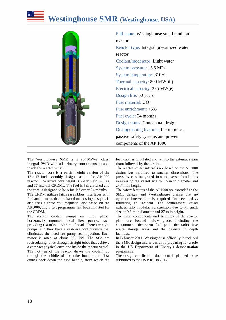
Westinghouse SMR (Westinghouse, USA)
Full name: Westinghouse small modular
reactor
Reactor type: Integral pressurized water
reactor
Coolant/moderator: Light water
System pressure: 15.5 MPa
System temperature: 310°C
Thermal capacity: 800 MW(th)
Electrical capacity: 225 MW(e)
Design life: 60 years
Fuel material: UO2
Fuel enrichment: <5%
Fuel cycle: 24 months
Design status: Conceptual design
Distinguishing features: Incorporates
passive safety systems and proven
components of the AP 1000
The Westinghouse SMR is a 200 MW(e) class,
integral PWR with all primary components located
inside the reactor vessel.
The reactor core is a partial height version of the
17 × 17 fuel assembly design used in the AP1000
reactor. The active core height is 2.4 m with 89 FAs
and 37 internal CRDMs. The fuel is 5% enriched and
the core is designed to be refuelled every 24 months.
The CRDM utilizes latch assemblies, interfaces with
fuel and controls that are based on existing designs. It
also uses a three coil magnetic jack based on the
AP1000, and a test programme has been initiated for
the CRDM.
The reactor coolant pumps are three phase,
horizontally mounted, axial flow pumps, each
providing 0.8 m3/s at 30.5 m of head. There are eight
pumps, and they have a seal-less configuration that
eliminates the need for pump seal injection. Each
motor is rated at about 260 kW. The SGs are
recirculating, once through straight tubes that achieve
a compact physical envelope inside the reactor vessel.
The hot leg of the reactor drives the coolant up
through the middle of the tube bundle; the flow
comes back down the tube bundle, from which the
feedwater is circulated and sent to the external steam
drum followed by the turbine.
The reactor vessel internals are based on the AP1000
design but modified to smaller dimensions. The
pressurizer is integrated into the vessel head, thus
minimizing the vessel size to 3.5 m in diameter and
24.7 m in height.
The safety features of the AP1000 are extended to the
SMR design, and Westinghouse claims that no
operator intervention is required for seven days
following an incident. The containment vessel
utilizes fully modular construction due to its small
size of 9.8 m in diameter and 27 m in height.
The main components and facilities of the reactor
plant are located below grade, including the
containment, the spent fuel pool, the radioactive
waste storage areas and the defence in depth
facilities.
In February 2011, Westinghouse officially introduced
the SMR design and is currently preparing for a role
in the US Department of Energy’s demonstration
programme.
The design certification document is planned to be
submitted to the US NRC in 2012.
19
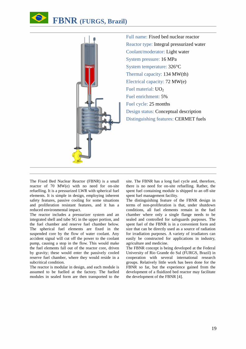
FBNR (FURGS, Brazil)
Full name: Fixed bed nuclear reactor
Reactor type: Integral pressurized water
Coolant/moderator: Light water
System pressure: 16 MPa
System temperature: 326°C
Thermal capacity: 134 MW(th)
Electrical capacity: 72 MW(e)
Fuel material: UO2
Fuel enrichment: 5%
Fuel cycle: 25 months
Design status: Conceptual description
Distinguishing features: CERMET fuels
The Fixed Bed Nuclear Reactor (FBNR) is a small
reactor of 70 MW(e) with no need for on-site
refuelling. It is a pressurized LWR with spherical fuel
elements. It is simple in design, employing inherent
safety features, passive cooling for some situations
and proliferation resistant features, and it has a
reduced environmental impact.
The reactor includes a pressurizer system and an
integrated shell and tube SG in the upper portion, and
the fuel chamber and reserve fuel chamber below.
The spherical fuel elements are fixed in the
suspended core by the flow of water coolant. Any
accident signal will cut off the power to the coolant
pump, causing a stop in the flow. This would make
the fuel elements fall out of the reactor core, driven
by gravity; these would enter the passively cooled
reserve fuel chamber, where they would reside in a
subcritical condition.
The reactor is modular in design, and each module is
assumed to be fuelled at the factory. The fuelled
modules in sealed form are then transported to the
site. The FBNR has a long fuel cycle and, therefore,
there is no need for on-site refuelling. Rather, the
spent fuel containing module is shipped to an off-site
spent fuel management facility.
The distinguishing feature of the FBNR design in
terms of non-proliferation is that, under shutdown
conditions, all fuel elements remain in the fuel
chamber where only a single flange needs to be
sealed and controlled for safeguards purposes. The
spent fuel of the FBNR is in a convenient form and
size that can be directly used as a source of radiation
for irradiation purposes. A variety of irradiators can
easily be constructed for applications in industry,
agriculture and medicine.
The FBNR concept is being developed at the Federal
University of Rio Grande do Sul (FURGS, Brazil) in
cooperation with several international research
groups. Relatively little work has been done for the
FBNR so far, but the experience gained from the
development of a fluidized bed reactor may facilitate
the development of the FBNR [4].
20
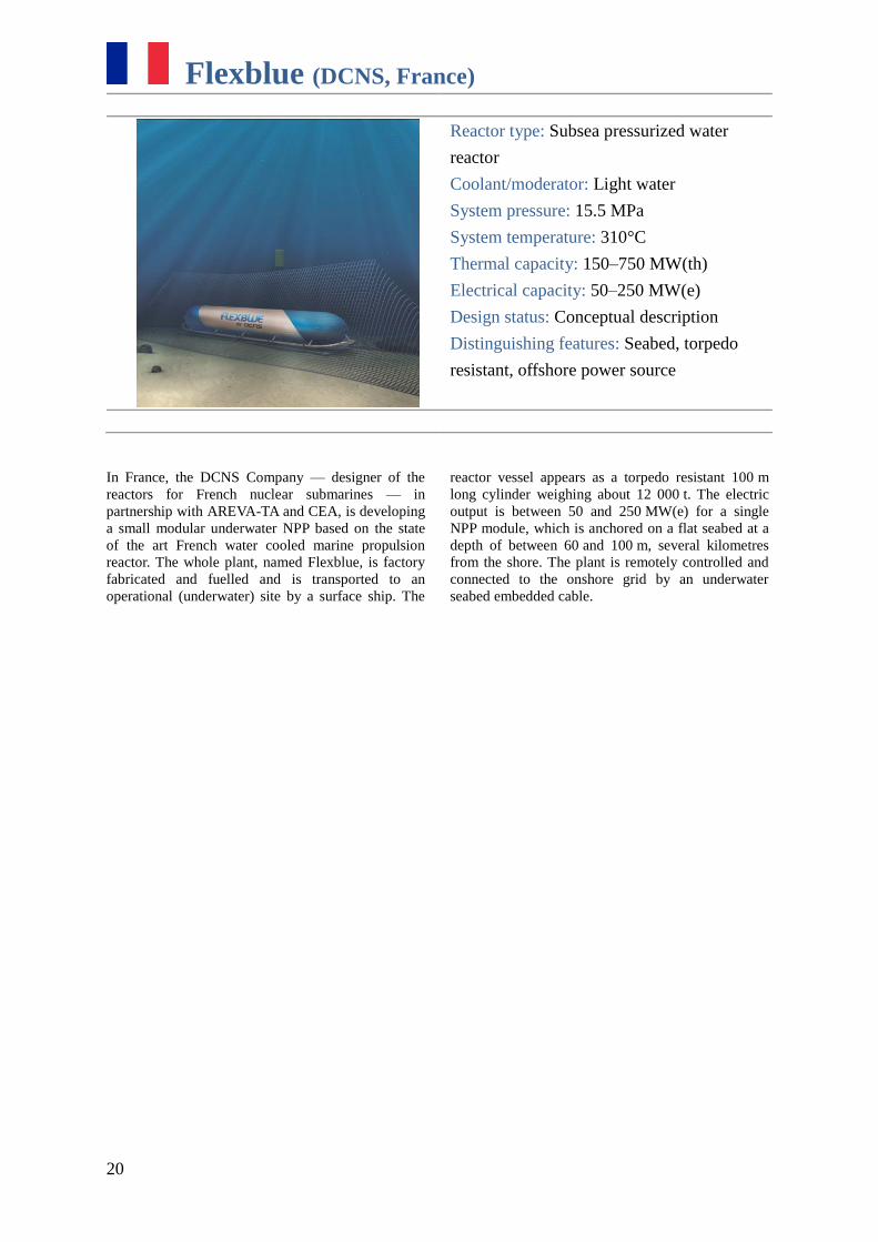
Flexblue (DCNS, France)
Reactor type: Subsea pressurized water
reactor
Coolant/moderator: Light water
System pressure: 15.5 MPa
System temperature: 310°C
Thermal capacity: 150–750 MW(th)
Electrical capacity: 50–250 MW(e)
Design status: Conceptual description
Distinguishing features: Seabed, torpedo
resistant, offshore power source
In France, the DCNS Company — designer of the
reactors for French nuclear submarines — in
partnership with AREVA-TA and CEA, is developing
a small modular underwater NPP based on the state
of the art French water cooled marine propulsion
reactor. The whole plant, named Flexblue, is factory
fabricated and fuelled and is transported to an
operational (underwater) site by a surface ship. The
reactor vessel appears as a torpedo resistant 100 m
long cylinder weighing about 12 000 t. The electric
output is between 50 and 250 MW(e) for a single
NPP module, which is anchored on a flat seabed at a
depth of between 60 and 100 m, several kilometres
from the shore. The plant is remotely controlled and
connected to the onshore grid by an underwater
seabed embedded cable.
HEAVY WATER REACTORS
22
EC6 (AECL, Canada)
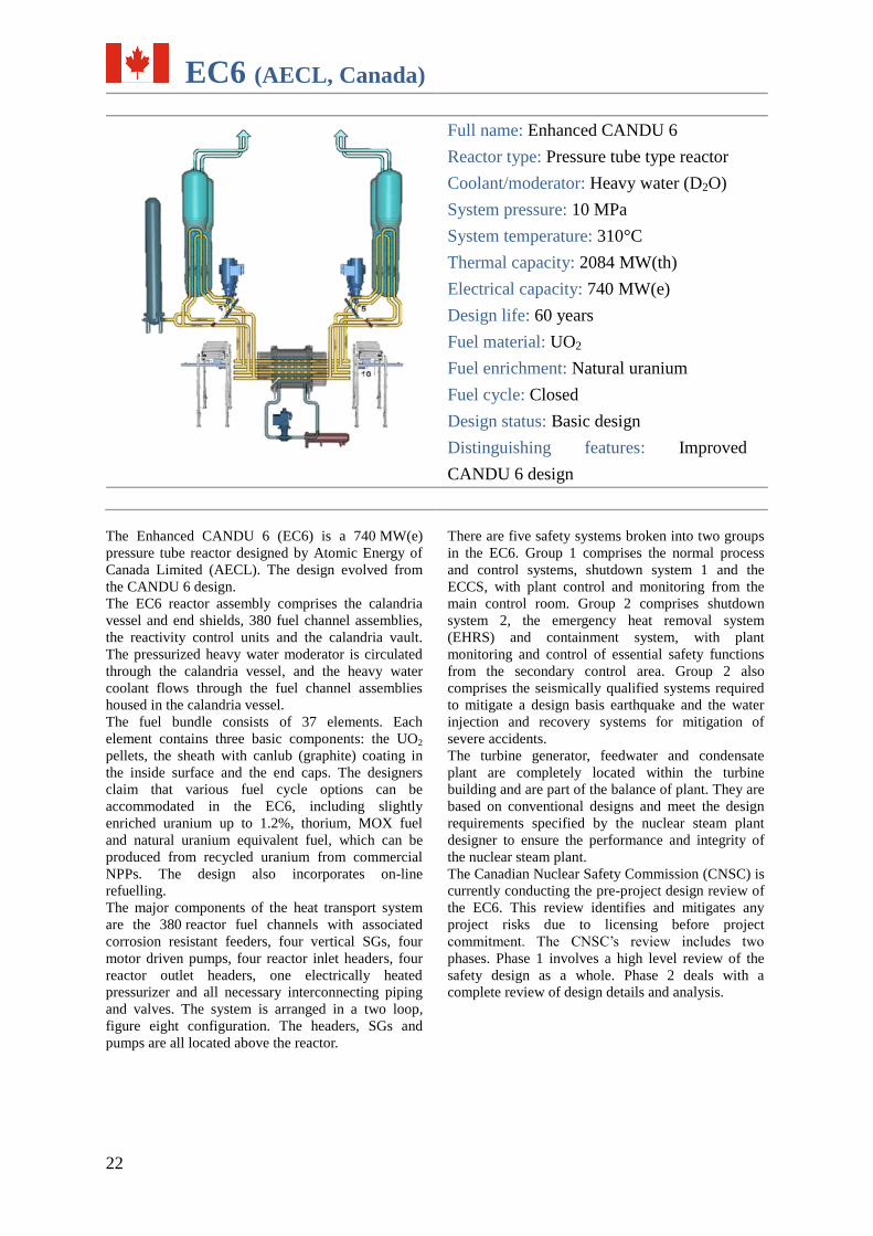
Full name: Enhanced CANDU 6
Reactor type: Pressure tube type reactor
Coolant/moderator: Heavy water (D2O)
System pressure: 10 MPa
System temperature: 310°C
Thermal capacity: 2084 MW(th)
Electrical capacity: 740 MW(e)
Design life: 60 years
Fuel material: UO2
Fuel enrichment: Natural uranium
Fuel cycle: Closed
Design status: Basic design
Distinguishing features: Improved
CANDU 6 design
The Enhanced CANDU 6 (EC6) is a 740 MW(e)
pressure tube reactor designed by Atomic Energy of
Canada Limited (AECL). The design evolved from
the CANDU 6 design. The EC6 reactor assembly comprises the calandria
vessel and end shields, 380 fuel channel assemblies,
the reactivity control units and the calandria vault.
The pressurized heavy water moderator is circulated
through the calandria vessel, and the heavy water
coolant flows through the fuel channel assemblies
housed in the calandria vessel.
The fuel bundle consists of 37 elements. Each
element contains three basic components: the UO2
pellets, the sheath with canlub (graphite) coating in
the inside surface and the end caps. The designers
claim that various fuel cycle options can be
accommodated in the EC6, including slightly
enriched uranium up to 1.2%, thorium, MOX fuel
and natural uranium equivalent fuel, which can be
produced from recycled uranium from commercial
NPPs. The design also incorporates on-line
refuelling.
The major components of the heat transport system
are the 380 reactor fuel channels with associated
corrosion resistant feeders, four vertical SGs, four
motor driven pumps, four reactor inlet headers, four
reactor outlet headers, one electrically heated
pressurizer and all necessary interconnecting piping
and valves. The system is arranged in a two loop,
figure eight configuration. The headers, SGs and
pumps are all located above the reactor.
There are five safety systems broken into two groups
in the EC6. Group 1 comprises the normal process
and control systems, shutdown system 1 and the
ECCS, with plant control and monitoring from the
main control room. Group 2 comprises shutdown
system 2, the emergency heat removal system
(EHRS) and containment system, with plant
monitoring and control of essential safety functions
from the secondary control area. Group 2 also
comprises the seismically qualified systems required
to mitigate a design basis earthquake and the water
injection and recovery systems for mitigation of
severe accidents.
The turbine generator, feedwater and condensate
plant are completely located within the turbine
building and are part of the balance of plant. They are
based on conventional designs and meet the design
requirements specified by the nuclear steam plant
designer to ensure the performance and integrity of
the nuclear steam plant.
The Canadian Nuclear Safety Commission (CNSC) is
currently conducting the pre-project design review of
the EC6. This review identifies and mitigates any
project risks due to licensing before project
commitment. The CNSC’s review includes two
phases. Phase 1 involves a high level review of the
safety design as a whole. Phase 2 deals with a
complete review of design details and analysis.
23
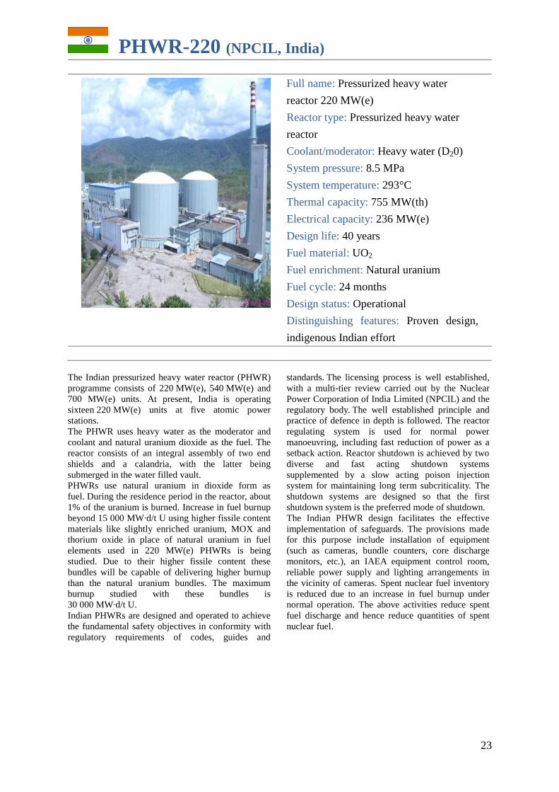
PHWR-220 (NPCIL, India)
Full name: Pressurized heavy water
reactor 220 MW(e)
Reactor type: Pressurized heavy water
reactor
Coolant/moderator: Heavy water (D20)
System pressure: 8.5 MPa
System temperature: 293°C
Thermal capacity: 755 MW(th)
Electrical capacity: 236 MW(e)
Design life: 40 years
Fuel material: UO2
Fuel enrichment: Natural uranium
Fuel cycle: 24 months
Design status: Operational
Distinguishing features: Proven design,
indigenous Indian effort
The Indian pressurized heavy water reactor (PHWR)
programme consists of 220 MW(e), 540 MW(e) and
700 MW(e) units. At present, India is operating
sixteen 220 MW(e) units at five atomic power
stations.
The PHWR uses heavy water as the moderator and
coolant and natural uranium dioxide as the fuel. The
reactor consists of an integral assembly of two end
shields and a calandria, with the latter being
submerged in the water filled vault.
PHWRs use natural uranium in dioxide form as
fuel. During the residence period in the reactor, about
1% of the uranium is burned. Increase in fuel burnup
beyond 15 000 MW∙d/t U using higher fissile content
materials like slightly enriched uranium, MOX and
thorium oxide in place of natural uranium in fuel
elements used in 220 MW(e) PHWRs is being
studied. Due to their higher fissile content these
bundles will be capable of delivering higher burnup
than the natural uranium bundles. The maximum
burnup studied with these bundles is
30 000 MW∙d/t U.
Indian PHWRs are designed and operated to achieve
the fundamental safety objectives in conformity with
regulatory requirements of codes, guides and
standards. The licensing process is well established,
with a multi-tier review carried out by the Nuclear
Power Corporation of India Limited (NPCIL) and the
regulatory body. The well established principle and
practice of defence in depth is followed. The reactor
regulating system is used for normal power
manoeuvring, including fast reduction of power as a
setback action. Reactor shutdown is achieved by two
diverse and fast acting shutdown systems
supplemented by a slow acting poison injection
system for maintaining long term subcriticality. The
shutdown systems are designed so that the first
shutdown system is the preferred mode of shutdown.
The Indian PHWR design facilitates the effective
implementation of safeguards. The provisions made
for this purpose include installation of equipment
(such as cameras, bundle counters, core discharge
monitors, etc.), an IAEA equipment control room,
reliable power supply and lighting arrangements in
the vicinity of cameras. Spent nuclear fuel inventory
is reduced due to an increase in fuel burnup under
normal operation. The above activities reduce spent
fuel discharge and hence reduce quantities of spent
nuclear fuel.

24
AHWR300-LEU (BARC, India)
Full name: Advanced heavy water reactor
with low enriched uranium and thorium
mixed oxide fuel
Reactor type: Pressure tube type heavy
water moderated reactor
Coolant/moderator: Light water/heavy
water (D2O)
System pressure: 7 MPa
System temperature: 285°C
Design life: 100 years
Thermal capacity: 920 MW(th)
Electrical capacity: 304 MW(e)
Fuel material:(Th, 233
U)–MOX and
(Th, Pu)–MOX
Fuel enrichment: 3.00–3.75% 233
U/2.5–4.0% Pu
Fuel cycle: Closed
Design status: Basic design
Distinguishing features: Mixed oxide
thorium closed fuel cycle; vertical cooling
channels
The Indian Advanced Heavy Water Reactor with Low
Enriched Uranium and Thorium Mixed Oxide Fuel
(AHWR300-LEU) was designed and developed by
the Bhabha Atomic Research Centre (BARC) to
achieve large scale use of thorium for the generation
of commercial nuclear power. This reactor is
designed to produce most of its power from thorium,
with no external input of 233
U in the equilibrium
cycle.
The AHWR300-LEU design utilizes a calandria
vessel housing the core. The calandria vessel is filled
with heavy water as the moderator and has vertical
cooling channels with boiling light water as the
primary coolant. The AHWR300-LEU circular fuel
cluster is designed with 30 (Th, 233
U)–MOX pins and
24 (Th, Pu)–MOX pins; 452 of the fuel clusters
comprise the full core. The AHWR300-LEU is also
designed to use a closed fuel cycle, recovering 233
U
and thorium from the spent fuel to be used in the
manufacture of fresh fuel.
The coolant circulation is driven by natural
convection through tail pipes to steam drums, where
steam is separated for running the turbine cycle.
During shutdown, passive valves establish
communication of steam drums with the isolation
condensers submerged inside an 8000 m3 gravity
driven water pool for decay heat removal under hot
shutdown conditions.
The reactor design’s safety features include a variety
of passive safety systems such as the injection of
emergency core coolant through rupture disks,
containment isolation following a large break LOCA
and passive poison injection by use of system steam
pressure in the event of active shutdown system
failure. The ECCS is designed to provide core
cooling for 72 h following an incident.
The primary function of the steam and feed system is
to transfer heat produced in the reactor core to the
turbine for production of electrical power. The steam
and feed system forms an interface between the main
heat transport system and the ultimate heat sink
(seawater) and provides the means for heat removal
at various reactor operating conditions. The steam
and feed system consists of the steam mains, turbo
generator and auxiliaries, condensing system,
condensate and feedwater heating system, steam
dumping and relief systems and on-line full
condensate flow purification. Construction of the
AHWR300-LEU is likely to commence in 2011.
Evaluation of probable sites is in progress.
GAS COOLED REACTORS
26
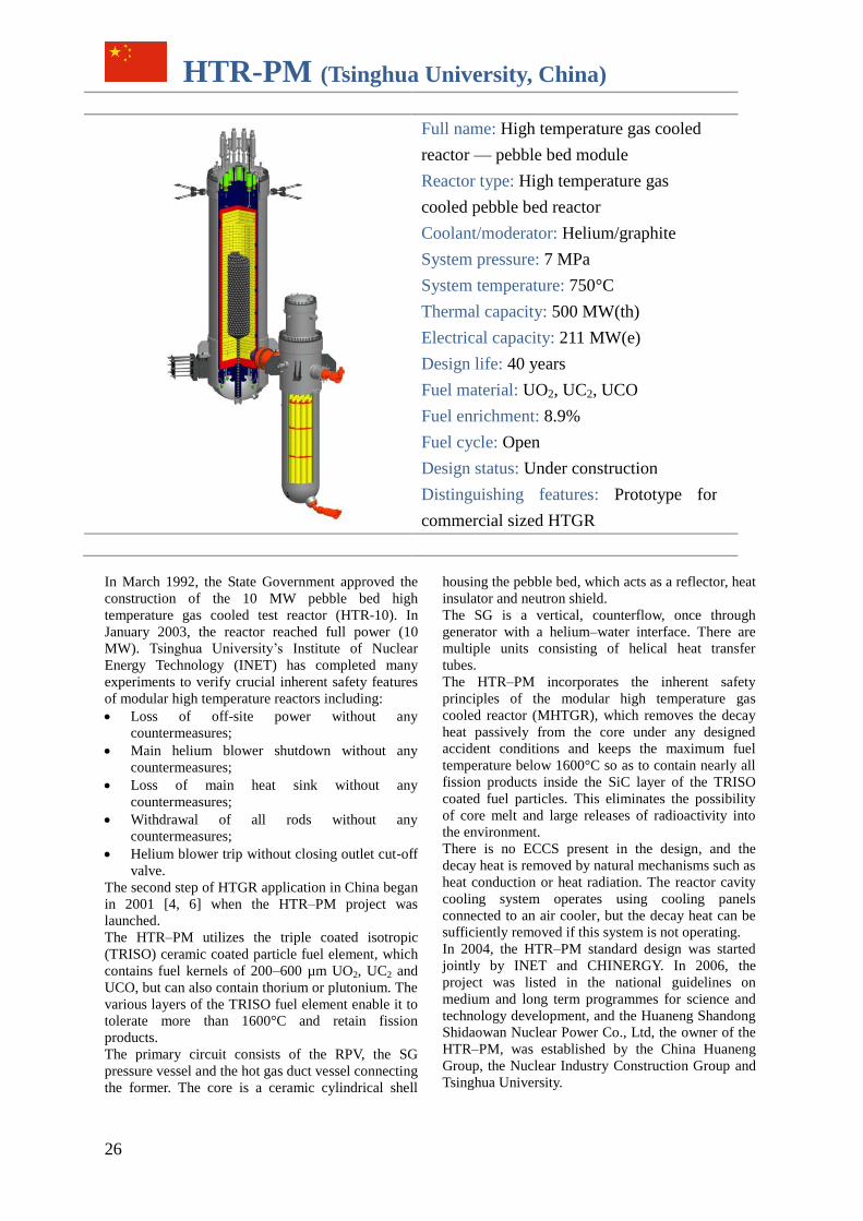
HTR-PM (Tsinghua University, China)
Full name: High temperature gas cooled
reactor — pebble bed module
Reactor type: High temperature gas
cooled pebble bed reactor
Coolant/moderator: Helium/graphite
System pressure: 7 MPa
System temperature: 750°C
Thermal capacity: 500 MW(th)
Electrical capacity: 211 MW(e)
Design life: 40 years
Fuel material: UO2, UC2, UCO
Fuel enrichment: 8.9%
Fuel cycle: Open
Design status: Under construction
Distinguishing features: Prototype for
commercial sized HTGR
In March 1992, the State Government approved the
construction of the 10 MW pebble bed high
temperature gas cooled test reactor (HTR-10). In
January 2003, the reactor reached full power (10
MW). Tsinghua University’s Institute of Nuclear
Energy Technology (INET) has completed many
experiments to verify crucial inherent safety features
of modular high temperature reactors including:
Loss of off-site power without any
countermeasures;
Main helium blower shutdown without any
countermeasures;
Loss of main heat sink without any
countermeasures;
Withdrawal of all rods without any
countermeasures;
Helium blower trip without closing outlet cut-off
valve.
The second step of HTGR application in China began
in 2001 [4, 6] when the HTR–PM project was
launched.
The HTR–PM utilizes the triple coated isotropic
(TRISO) ceramic coated particle fuel element, which
contains fuel kernels of 200–600 µm UO2, UC2 and
UCO, but can also contain thorium or plutonium. The
various layers of the TRISO fuel element enable it to
tolerate more than 1600°C and retain fission
products.
The primary circuit consists of the RPV, the SG
pressure vessel and the hot gas duct vessel connecting
the former. The core is a ceramic cylindrical shell
housing the pebble bed, which acts as a reflector, heat
insulator and neutron shield.
The SG is a vertical, counterflow, once through
generator with a helium–water interface. There are
multiple units consisting of helical heat transfer
tubes.
The HTR–PM incorporates the inherent safety
principles of the modular high temperature gas
cooled reactor (MHTGR), which removes the decay
heat passively from the core under any designed
accident conditions and keeps the maximum fuel
temperature below 1600°C so as to contain nearly all
fission products inside the SiC layer of the TRISO
coated fuel particles. This eliminates the possibility
of core melt and large releases of radioactivity into
the environment.
There is no ECCS present in the design, and the
decay heat is removed by natural mechanisms such as
heat conduction or heat radiation. The reactor cavity
cooling system operates using cooling panels
connected to an air cooler, but the decay heat can be
sufficiently removed if this system is not operating.
In 2004, the HTR–PM standard design was started
jointly by INET and CHINERGY. In 2006, the
project was listed in the national guidelines on
medium and long term programmes for science and
technology development, and the Huaneng Shandong
Shidaowan Nuclear Power Co., Ltd, the owner of the
HTR–PM, was established by the China Huaneng
Group, the Nuclear Industry Construction Group and
Tsinghua University.
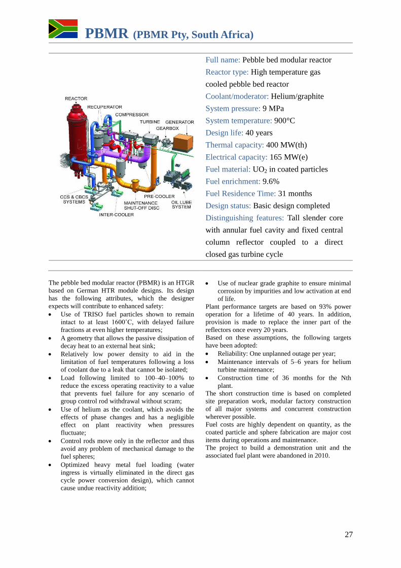
27
PBMR (PBMR Pty, South Africa)
Full name: Pebble bed modular reactor
Reactor type: High temperature gas
cooled pebble bed reactor
Coolant/moderator: Helium/graphite
System pressure: 9 MPa
System temperature: 900°C
Design life: 40 years
Thermal capacity: 400 MW(th)
Electrical capacity: 165 MW(e)
Fuel material: UO2 in coated particles
Fuel enrichment: 9.6%
Fuel Residence Time: 31 months
Design status: Basic design completed
Distinguishing features: Tall slender core
with annular fuel cavity and fixed central
column reflector coupled to a direct
closed gas turbine cycle
The pebble bed modular reactor (PBMR) is an HTGR
based on German HTR module designs. Its design
has the following attributes, which the designer
expects will contribute to enhanced safety:
Use of TRISO fuel particles shown to remain
intact to at least 1600˚C, with delayed failure
fractions at even higher temperatures;
A geometry that allows the passive dissipation of
decay heat to an external heat sink;
Relatively low power density to aid in the
limitation of fuel temperatures following a loss
of coolant due to a leak that cannot be isolated;
Load following limited to 100–40–100% to
reduce the excess operating reactivity to a value
that prevents fuel failure for any scenario of
group control rod withdrawal without scram;
Use of helium as the coolant, which avoids the
effects of phase changes and has a negligible
effect on plant reactivity when pressures
fluctuate;
Control rods move only in the reflector and thus
avoid any problem of mechanical damage to the
fuel spheres;
Optimized heavy metal fuel loading (water
ingress is virtually eliminated in the direct gas
cycle power conversion design), which cannot
cause undue reactivity addition;
Use of nuclear grade graphite to ensure minimal
corrosion by impurities and low activation at end
of life.
Plant performance targets are based on 93% power
operation for a lifetime of 40 years. In addition,
provision is made to replace the inner part of the
reflectors once every 20 years.
Based on these assumptions, the following targets
have been adopted:
Reliability: One unplanned outage per year;
Maintenance intervals of 5–6 years for helium
turbine maintenance;
Construction time of 36 months for the Nth
plant.
The short construction time is based on completed
site preparation work, modular factory construction
of all major systems and concurrent construction
wherever possible.
Fuel costs are highly dependent on quantity, as the
coated particle and sphere fabrication are major cost
items during operations and maintenance.
The project to build a demonstration unit and the
associated fuel plant were abandoned in 2010.
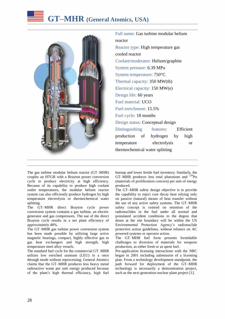
28
GT–MHR (General Atomics, USA)
Full name: Gas turbine modular helium
reactor
Reactor type: High temperature gas
cooled reactor
Coolant/moderator: Helium/graphite
System pressure: 6.39 MPa
System temperature: 750°C
Thermal capacity: 350 MW(th)
Electrical capacity: 150 MW(e)
Design life: 60 years
Fuel material: UCO
Fuel enrichment: 15.5%
Fuel cycle: 18 months
Design status: Conceptual design
Distinguishing features: Efficient
production of hydrogen by high
temperature electrolysis or
thermochemical water splitting
The gas turbine modular helium reactor (GT–MHR)
couples an HTGR with a Brayton power conversion
cycle to produce electricity at high efficiency.
Because of its capability to produce high coolant
outlet temperatures, the modular helium reactor
system can also efficiently produce hydrogen by high
temperature electrolysis or thermochemical water
splitting.
The GT–MHR direct Brayton cycle power
conversion system contains a gas turbine, an electric
generator and gas compressors. The use of the direct
Brayton cycle results in a net plant efficiency of
approximately 48%.
The GT–MHR gas turbine power conversion system
has been made possible by utilizing large active
magnetic bearings, compact, highly effective gas to
gas heat exchangers and high strength, high
temperature steel alloy vessels.
The standard fuel cycle for the commercial GT–MHR
utilizes low enriched uranium (LEU) in a once
through mode without reprocessing. General Atomics
claims that the GT–MHR produces less heavy metal
radioactive waste per unit energy produced because
of the plant’s high thermal efficiency, high fuel
burnup and lower fertile fuel inventory. Similarly, the
GT–MHR produces less total plutonium and 239
Pu
(materials of proliferation concern) per unit of energy
produced.
The GT–MHR safety design objective is to provide
the capability to reject core decay heat relying only
on passive (natural) means of heat transfer without
the use of any active safety systems. The GT–MHR
safety concept is centred on retention of the
radionuclides in the fuel under all normal and
postulated accident conditions to the degree that
doses at the site boundary will be within the US
Environmental Protection Agency’s radionuclide
protective action guidelines, without reliance on AC
powered systems or operator action.
The GT–MHR fuel form presents formidable
challenges to diversion of materials for weapons
production, as either fresh or as spent fuel.
Pre-application licensing interactions with the NRC
began in 2001 including submission of a licensing
plan. From a technology development standpoint, the
path forward for deployment of the GT–MHR
technology is necessarily a demonstration project,
such as the next generation nuclear plant project [1].
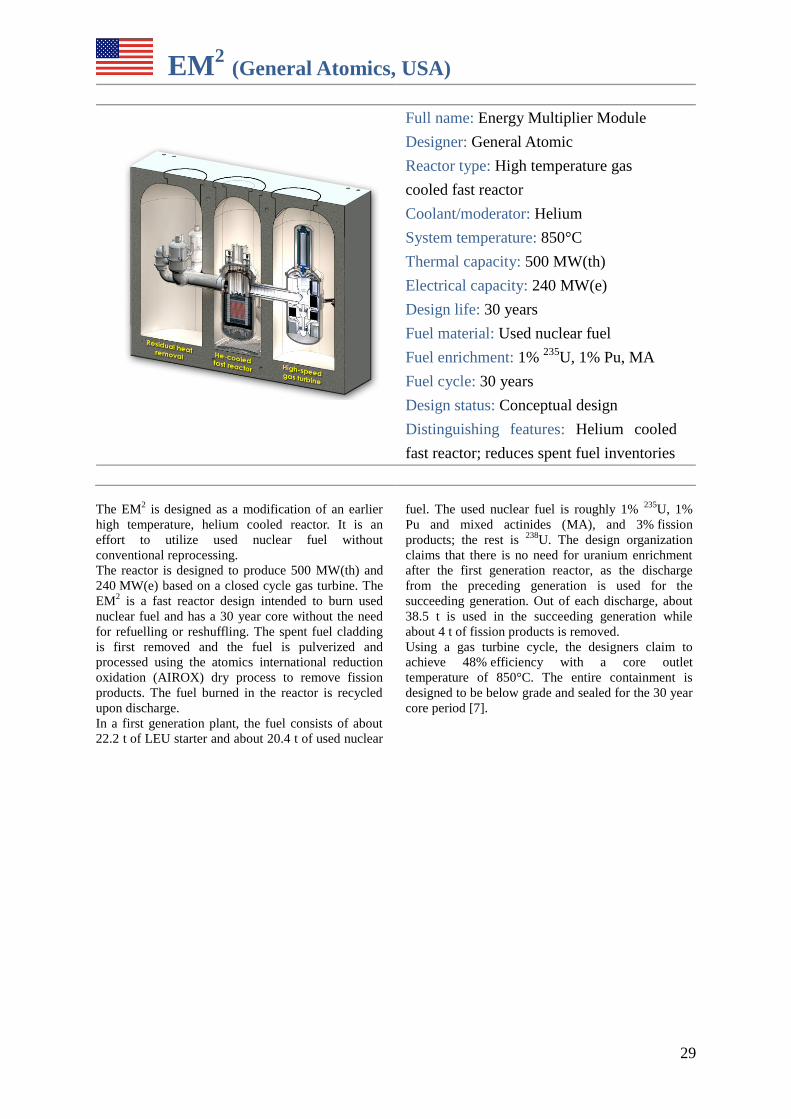
29
EM2 (General Atomics, USA)
Full name: Energy Multiplier Module
Designer: General Atomic
Reactor type: High temperature gas
cooled fast reactor
Coolant/moderator: Helium
System temperature: 850°C
Thermal capacity: 500 MW(th)
Electrical capacity: 240 MW(e)
Design life: 30 years
Fuel material: Used nuclear fuel
Fuel enrichment: 1% 235
U, 1% Pu, MA
Fuel cycle: 30 years
Design status: Conceptual design
Distinguishing features: Helium cooled
fast reactor; reduces spent fuel inventories
The EM2 is designed as a modification of an earlier
high temperature, helium cooled reactor. It is an
effort to utilize used nuclear fuel without
conventional reprocessing.
The reactor is designed to produce 500 MW(th) and
240 MW(e) based on a closed cycle gas turbine. The
EM2 is a fast reactor design intended to burn used
nuclear fuel and has a 30 year core without the need
for refuelling or reshuffling. The spent fuel cladding
is first removed and the fuel is pulverized and
processed using the atomics international reduction
oxidation (AIROX) dry process to remove fission
products. The fuel burned in the reactor is recycled
upon discharge.
In a first generation plant, the fuel consists of about
22.2 t of LEU starter and about 20.4 t of used nuclear
fuel. The used nuclear fuel is roughly 1% 235
U, 1%
Pu and mixed actinides (MA), and 3% fission
products; the rest is 238
U. The design organization
claims that there is no need for uranium enrichment
after the first generation reactor, as the discharge
from the preceding generation is used for the
succeeding generation. Out of each discharge, about
38.5 t is used in the succeeding generation while
about 4 t of fission products is removed.
Using a gas turbine cycle, the designers claim to
achieve 48% efficiency with a core outlet
temperature of 850°C. The entire containment is
designed to be below grade and sealed for the 30 year
core period [7].

LIQUID METAL COOLED REACTORS
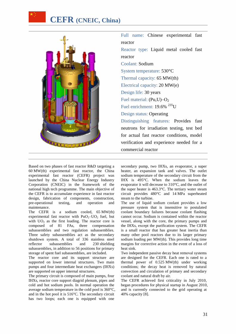
31
CEFR (CNEIC, China)
Full name: Chinese experimental fast
reactor
Reactor type: Liquid metal cooled fast
reactor
Coolant: Sodium
System temperature: 530°C
Thermal capacity: 65 MW(th)
Electrical capacity: 20 MW(e)
Design life: 30 years
Fuel material: (Pu,U)–O2
Fuel enrichment: 19.6% 235
U
Design status: Operating
Distinguishing features: Provides fast
neutrons for irradiation testing, test bed
for actual fast reactor conditions, model
verification and experience needed for a
commercial reactor
Based on two phases of fast reactor R&D targeting a
60 MW(th) experimental fast reactor, the China
experimental fast reactor (CEFR) project was
launched by the China Nuclear Energy Industry
Corporation (CNEIC) in the framework of the
national high tech programme. The main objective of
the CEFR is to accumulate experience in fast reactor
design, fabrication of components, construction,
pre-operational testing, and operation and
maintenance.
The CEFR is a sodium cooled, 65 MW(th)
experimental fast reactor with PuO2–UO2 fuel, but
with UO2 as the first loading. The reactor core is
composed of 81 FAs, three compensation
subassemblies and two regulation subassemblies.
Three safety subassemblies act as the secondary
shutdown system. A total of 336 stainless steel
reflector subassemblies and 230 shielding
subassemblies, in addition to 56 positions for primary
storage of spent fuel subassemblies, are included.
The reactor core and its support structure are
supported on lower internal structures. Two main
pumps and four intermediate heat exchangers (IHXs)
are supported on upper internal structures.
The primary circuit is composed of main pumps, four
IHXs, reactor core support diagrid plenum, pipes and
cold and hot sodium pools. In normal operation the
average sodium temperature in the cold pool is 360°C,
and in the hot pool it is 516°C. The secondary circuit
has two loops; each one is equipped with one
secondary pump, two IHXs, an evaporator, a super
heater, an expansion tank and valves. The outlet
sodium temperature of the secondary circuit from the
IHX is 495°C. When the sodium leaves the
evaporator it will decrease to 310°C, and the outlet of
the super heater is 463.3°C. The tertiary water steam
circuit provides 480°C and 14 MPa superheated
steam to the turbine.
The use of liquid sodium coolant provides a low
pressure system that is insensitive to postulated
coolant boundary failures because coolant flashing
cannot occur. Sodium is contained within the reactor
vessel, along with the core, the primary pumps and
the IHXs, except the purification system. The CEFR
is a small reactor that has greater heat inertia than
many other pool reactors due to its larger primary
sodium loading per MW(th). This provides long time
margins for corrective action in the event of a loss of
heat sink.
Two independent passive decay heat removal systems
are designed for the CEFR. Each one is rated to a
thermal power of 0.525 MW(th) under working
conditions; the decay heat is removed by natural
convection and circulation of primary and secondary
coolant and natural draft by air.
The CEFR achieved first criticality in July 2010,
began procedures for physical startup in August 2010,
and is currently connected to the grid operating at
40% capacity [8].
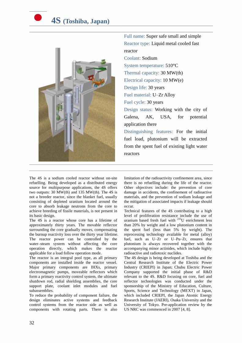
32
4S (Toshiba, Japan)
Full name: Super safe small and simple
Reactor type: Liquid metal cooled fast
reactor
Coolant: Sodium
System temperature: 510°C
Thermal capacity: 30 MW(th)
Electrical capacity: 10 MW(e)
Design life: 30 years
Fuel material: U–Zr Alloy
Fuel cycle: 30 years
Design status: Working with the city of
Galena, AK, USA, for potential
application there
Distinguishing features: For the initial
fuel load, plutonium will be extracted
from the spent fuel of existing light water
reactors
The 4S is a sodium cooled reactor without on-site
refuelling. Being developed as a distributed energy
source for multipurpose applications, the 4S offers
two outputs: 30 MW(th) and 135 MW(th). The 4S is
not a breeder reactor, since the blanket fuel, usually
consisting of depleted uranium located around the
core to absorb leakage neutrons from the core to
achieve breeding of fissile materials, is not present in
its basic design.
The 4S is a reactor whose core has a lifetime of
approximately thirty years. The movable reflector
surrounding the core gradually moves, compensating
the burnup reactivity loss over the thirty year lifetime.
The reactor power can be controlled by the
water–steam system without affecting the core
operation directly, which makes the reactor
applicable for a load follow operation mode.
The reactor is an integral pool type, as all primary
components are installed inside the reactor vessel.
Major primary components are IHXs, primary
electromagnetic pumps, moveable reflectors which
form a primary reactivity control system, the ultimate
shutdown rod, radial shielding assemblies, the core
support plate, coolant inlet modules and fuel
subassemblies.
To reduce the probability of component failure, the
design eliminates active systems and feedback
control systems from the reactor side as well as
components with rotating parts. There is also
limitation of the radioactivity confinement area, since
there is no refuelling during the life of the reactor.
Other objectives include: the prevention of core
damage in accidents, the confinement of radioactive
materials, and the prevention of sodium leakage and
the mitigation of associated impacts if leakage should
occur.
Technical features of the 4S contributing to a high
level of proliferation resistance include the use of
uranium based fresh fuel with 235
U enrichment less
than 20% by weight and a low plutonium content in
the spent fuel (less than 5% by weight). The
reprocessing technology available for metal (alloy)
fuel, such as U–Zr or U–Pu–Zr, ensures that
plutonium is always recovered together with the
accompanying minor actinides, which include highly
radioactive and radiotoxic nuclides.
The 4S design is being developed at Toshiba and the
Central Research Institute of the Electric Power
Industry (CRIEPI) in Japan; Chubu Electric Power
Company supported the initial phase of R&D
relevant to the 4S. R&D focusing on core, fuel and
reflector technologies was conducted under the
sponsorship of the Ministry of Education, Culture,
Sports, Science and Technology (MEXT) in Japan,
which included CRIEPI, the Japan Atomic Energy
Research Institute (JAERI), Osaka University and the
University of Tokyo. Pre-application review by the
US NRC was commenced in 2007 [4, 8].
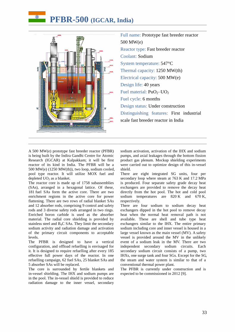
33
PFBR-500 (IGCAR, India)
Full name: Prototype fast breeder reactor
500 MW(e)
Reactor type: Fast breeder reactor
Coolant: Sodium
System temperature: 547°C
Thermal capacity: 1250 MW(th)
Electrical capacity: 500 MW(e)
Design life: 40 years
Fuel material: PuO2–UO2
Fuel cycle: 6 months
Design status: Under construction
Distinguishing features: First industrial
scale fast breeder reactor in India
A 500 MW(e) prototype fast breeder reactor (PFBR)
is being built by the Indira Gandhi Centre for Atomic
Research (IGCAR) at Kalpakkam; it will be first
reactor of its kind in India. The PFBR will be a
500 MW(e) (1250 MW(th)), two loop, sodium cooled,
pool type reactor. It will utilize MOX fuel and
depleted UO2 as a blanket.
The reactor core is made up of 1758 subassemblies
(SAs), arranged in a hexagonal lattice. Of these,
181 fuel SAs form the active core. There are two
enrichment regions in the active core for power
flattening. There are two rows of radial blanket SAs
and 12 absorber rods, comprising 9 control and safety
rods and 3 diverse safety rods arranged in two rings.
Enriched boron carbide is used as the absorber
material. The radial core shielding is provided by
stainless steel and B4C SAs. They limit the secondary
sodium activity and radiation damage and activation
of the primary circuit components to acceptable
levels.
The PFBR is designed to have a vertical
configuration, and offload refuelling is envisaged for
it. It is designed to require refuelling after every 185
effective full power days of the reactor. In one
refuelling campaign, 62 fuel SAs, 25 blanket SAs and
5 absorber SAs will be replaced.
The core is surrounded by fertile blankets and
in-vessel shielding. The IHX and sodium pumps are
in the pool. The in-vessel shield is provided to reduce
radiation damage to the inner vessel, secondary
sodium activation, activation of the IHX and sodium
pumps, and axial leakages through the bottom fission
product gas plenum. Mockup shielding experiments
were carried out to optimize design of this in-vessel
shield.
There are eight integrated SG units, four per
secondary loop where steam at 763 K and 17.2 MPa
is produced. Four separate safety grade decay heat
exchangers are provided to remove the decay heat
directly from the hot pool. The hot and cold pool
sodium temperatures are 820 K and 670 K,
respectively.
There are four sodium to sodium decay heat
exchangers dipped in the hot pool to remove decay
heat when the normal heat removal path is not
available. These are shell and tube type heat
exchangers similar to the IHX. The entire primary
sodium including core and inner vessel is housed in a
large vessel known as the main vessel (MV). A safety
vessel is provided around the MV in the unlikely
event of a sodium leak in the MV. There are two
independent secondary sodium circuits. Each
secondary sodium circuit consists of a pump, two
IHXs, one surge tank and four SGs. Except for the SG,
the steam and water system is similar to that of a
conventional thermal power plant.
The PFBR is currently under construction and is
expected to be commissioned in 2012 [9].
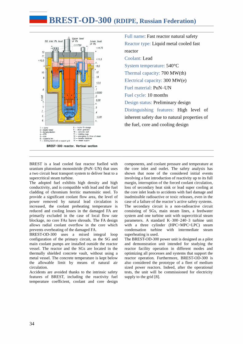
34
BREST-OD-300 (RDIPE, Russian Federation)
Full name: Fast reactor natural safety
Reactor type: Liquid metal cooled fast
reactor
Coolant: Lead
System temperature: 540°C
Thermal capacity: 700 MW(th)
Electrical capacity: 300 MW(e)
Fuel material: PuN–UN
Fuel cycle: 10 months
Design status: Preliminary design
Distinguishing features: High level of
inherent safety due to natural properties of
the fuel, core and cooling design
BREST is a lead cooled fast reactor fuelled with
uranium plutonium mononitride (PuN–UN) that uses
a two circuit heat transport system to deliver heat to a
supercritical steam turbine.
The adopted fuel exhibits high density and high
conductivity, and is compatible with lead and the fuel
cladding of chromium ferritic martensitic steel. To
provide a significant coolant flow area, the level of
power removed by natural lead circulation is
increased, the coolant preheating temperature is
reduced and cooling losses in the damaged FA are
primarily excluded in the case of local flow rate
blockage, no core FAs have shrouds. The FA design
allows radial coolant overflow in the core which
prevents overheating of the damaged FA.
BREST-OD-300 uses a mixed integral loop
configuration of the primary circuit, as the SG and
main coolant pumps are installed outside the reactor
vessel. The reactor and the SGs are located in the
thermally shielded concrete vault, without using a
metal vessel. The concrete temperature is kept below
the allowable limit by means of natural air
circulation.
Accidents are avoided thanks to the intrinsic safety
features of BREST, including the reactivity fuel
temperature coefficient, coolant and core design
components, and coolant pressure and temperature at
the core inlet and outlet. The safety analysis has
shown that none of the considered initial events
involving a fast introduction of reactivity up to its full
margin, interruption of the forced coolant circulation,
loss of secondary heat sink or lead super cooling at
the core inlet leads to accidents with fuel damage and
inadmissible radioactive or toxic releases, even in the
case of a failure of the reactor’s active safety systems.
The secondary circuit is a non-radioactive circuit
consisting of SGs, main steam lines, a feedwater
system and one turbine unit with supercritical steam
parameters. A standard K–300–240–3 turbine unit
with a three cylinder (HPC+MPC+LPC) steam
condensation turbine with intermediate steam
superheating is used.
The BREST-OD-300 power unit is designed as a pilot
and demonstration unit intended for studying the
reactor facility operation in different modes and
optimizing all processes and systems that support the
reactor operation. Furthermore, BREST-OD-300 is
also considered the prototype of a fleet of medium
sized power reactors. Indeed, after the operational
tests, the unit will be commissioned for electricity
supply to the grid [8].
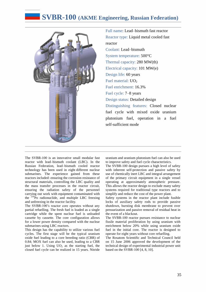
35
SVBR-100 (AKME Engineering, Russian Federation)
Full name: Lead–bismuth fast reactor
Reactor type: Liquid metal cooled fast
reactor
Coolant: Lead–bismuth
System temperature: 500°C
Thermal capacity: 280 MW(th)
Electrical capacity: 101 MW(e)
Design life: 60 years
Fuel material: UO2
Fuel enrichment: 16.3%
Fuel cycle: 7–8 years
Design status: Detailed design
Distinguishing features: Closed nuclear
fuel cycle with mixed oxide uranium
plutonium fuel, operation in a fuel
self-sufficient mode
The SVBR-100 is an innovative small modular fast
reactor with lead–bismuth coolant (LBC). In the
Russian Federation, lead–bismuth cooled reactor
technology has been used in eight different nuclear
submarines. The experience gained from these
reactors included: ensuring the corrosion resistance of
structural materials, controlling the LBC quality and
the mass transfer processes in the reactor circuit,
ensuring the radiation safety of the personnel
carrying out work with equipment contaminated with
the 210
Po radionuclide, and multiple LBC freezing
and unfreezing in the reactor facility.
The SVBR-100’s reactor core operates without any
partial refuelling. The fresh fuel is loaded as a single
cartridge while the spent nuclear fuel is unloaded
cassette by cassette. The core configuration allows
for a lower power density compared with the nuclear
submarines using LBC reactors.
This design has the capability to utilize various fuel
cycles. The first stage will be the typical uranium
oxide fuel leading to a core breeding ratio (CBR) of
0.84; MOX fuel can also be used, leading to a CBR
just below 1. Using UO2 as the starting fuel, the
closed fuel cycle can be realized in 15 years. Nitride
uranium and uranium plutonium fuel can also be used
to improve safety and fuel cycle characteristics.
The SVBR-100 design pursues a high level of safety
with inherent self-protection and passive safety by
use of chemically inert LBC and integral arrangement
of the primary circuit equipment in a single vessel
operating at approximately atmospheric pressure.
This allows the reactor design to exclude many safety
systems required for traditional type reactors and to
simplify and reduce the cost of the power plant.
Safety systems in the reactor plant include fusible
locks of auxiliary safety rods to provide passive
shutdown, bursting disk membrane to prevent over
pressurization and passive removal of residual heat in
the event of a blackout.
The SVBR-100 reactor pursues resistance to nuclear
fissile material proliferation by using uranium with
enrichment below 20% while using uranium oxide
fuel in the initial core. The reactor is designed to
operate for eight years without core refuelling.
The Rosatom Scientific and Technical Council held
on 15 June 2006 approved the development of the
technical design of experimental industrial power unit
based on the SVBR-100 [4, 8, 10].
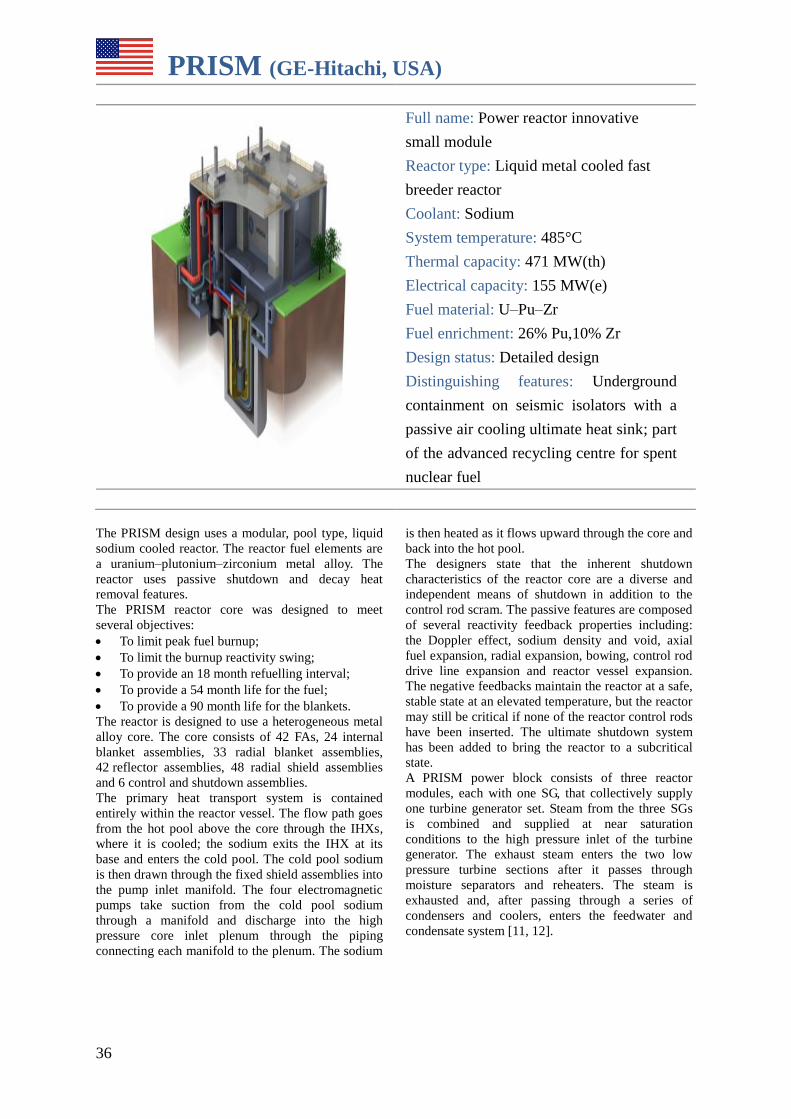
36
PRISM (GE-Hitachi, USA)
Full name: Power reactor innovative
small module
Reactor type: Liquid metal cooled fast
breeder reactor
Coolant: Sodium
System temperature: 485°C
Thermal capacity: 471 MW(th)
Electrical capacity: 155 MW(e)
Fuel material: U–Pu–Zr
Fuel enrichment: 26% Pu,10% Zr
Design status: Detailed design
Distinguishing features: Underground
containment on seismic isolators with a
passive air cooling ultimate heat sink; part
of the advanced recycling centre for spent
nuclear fuel
The PRISM design uses a modular, pool type, liquid
sodium cooled reactor. The reactor fuel elements are
a uranium–plutonium–zirconium metal alloy. The
reactor uses passive shutdown and decay heat
removal features.
The PRISM reactor core was designed to meet
several objectives:
To limit peak fuel burnup;
To limit the burnup reactivity swing;
To provide an 18 month refuelling interval;
To provide a 54 month life for the fuel;
To provide a 90 month life for the blankets.
The reactor is designed to use a heterogeneous metal
alloy core. The core consists of 42 FAs, 24 internal
blanket assemblies, 33 radial blanket assemblies,
42 reflector assemblies, 48 radial shield assemblies
and 6 control and shutdown assemblies.
The primary heat transport system is contained
entirely within the reactor vessel. The flow path goes
from the hot pool above the core through the IHXs,
where it is cooled; the sodium exits the IHX at its
base and enters the cold pool. The cold pool sodium
is then drawn through the fixed shield assemblies into
the pump inlet manifold. The four electromagnetic
pumps take suction from the cold pool sodium
through a manifold and discharge into the high
pressure core inlet plenum through the piping
connecting each manifold to the plenum. The sodium
is then heated as it flows upward through the core and
back into the hot pool.
The designers state that the inherent shutdown
characteristics of the reactor core are a diverse and
independent means of shutdown in addition to the
control rod scram. The passive features are composed
of several reactivity feedback properties including:
the Doppler effect, sodium density and void, axial
fuel expansion, radial expansion, bowing, control rod
drive line expansion and reactor vessel expansion.
The negative feedbacks maintain the reactor at a safe,
stable state at an elevated temperature, but the reactor
may still be critical if none of the reactor control rods
have been inserted. The ultimate shutdown system
has been added to bring the reactor to a subcritical
state.
A PRISM power block consists of three reactor
modules, each with one SG, that collectively supply
one turbine generator set. Steam from the three SGs
is combined and supplied at near saturation
conditions to the high pressure inlet of the turbine
generator. The exhaust steam enters the two low
pressure turbine sections after it passes through
moisture separators and reheaters. The steam is
exhausted and, after passing through a series of
condensers and coolers, enters the feedwater and
condensate system [11, 12].
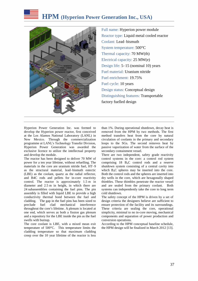
37
HPM (Hyperion Power Generation Inc., USA)
Full name: Hyperion power module
Reactor type: Liquid metal cooled reactor
Coolant: Lead–bismuth
System temperature: 500°C
Thermal capacity: 70 MW(th)
Electrical capacity: 25 MW(e)
Design life: 5–15 (nominal 10) years
Fuel material: Uranium nitride
Fuel enrichment: 19.75%
Fuel cycle: 10 years
Design status: Conceptual design
Distinguishing features: Transportable
factory fuelled design
Hyperion Power Generation Inc. was formed to
develop the Hyperion power reactor, first conceived
at the Los Alamos National Laboratory (LANL) in
New Mexico. Through the commercialization
programme at LANL’s Technology Transfer Division,
Hyperion Power Generation was awarded the
exclusive licence to utilize the intellectual property
and develop the module.
The reactor has been designed to deliver 70 MW of
power for a ten year lifetime, without refuelling. The
materials in the core are uranium nitride fuel, HT–9
as the structural material, lead–bismuth eutectic
(LBE) as the coolant, quartz as the radial reflector,
and B4C rods and pellets for in-core reactivity
control. The reactor is approximately 1.5 m in
diameter and 2.5 m in height, in which there are
24 subassemblies containing the fuel pins. The pin
assembly is filled with liquid LBE to provide a high
conductivity thermal bond between the fuel and
cladding. The gap in the fuel pins has been sized to
preclude fuel clad mechanical interference
throughout the core’s lifetime. A plenum is located at
one end, which serves as both a fission gas plenum
and a repository for the LBE inside the pin as the fuel
swells with burnup.
The core coolant is LBE, with a mixed mean exit
temperature of 500°C. This temperature limits the
cladding temperature so that maximum cladding
creep over the 10 year lifetime of the reactor is less
than 1%. During operational shutdown, decay heat is
removed from the HPM by two methods. The first
method transfers heat from the core by natural
circulation of coolants in the primary and secondary
loops to the SGs. The second removes heat by
passive vaporization of water from the surface of the
secondary containment vessel.
There are two independent, safety grade reactivity
control systems in the core: a control rod system
comprising 18 B4C control rods and a reserve
shutdown system consisting of a central cavity into
which B4C spheres may be inserted into the core.
Both the control rods and the spheres are inserted into
dry wells in the core, which are hexagonally shaped
thimbles. These thimbles penetrate the reactor vessel
and are sealed from the primary coolant. Both
systems can independently take the core to long term
cold shutdown.
The safety concept of the HPM is driven by a set of
design criteria the designers believe are sufficient to
ensure protection of the facility and its surroundings.
These criteria are sealing the core, operational
simplicity, minimal to no in-core moving, mechanical
components and separation of power production and
conversion operations.
According to the HPM conceptual baseline schedule,
the HPM design will be finalized in March 2012 [13].
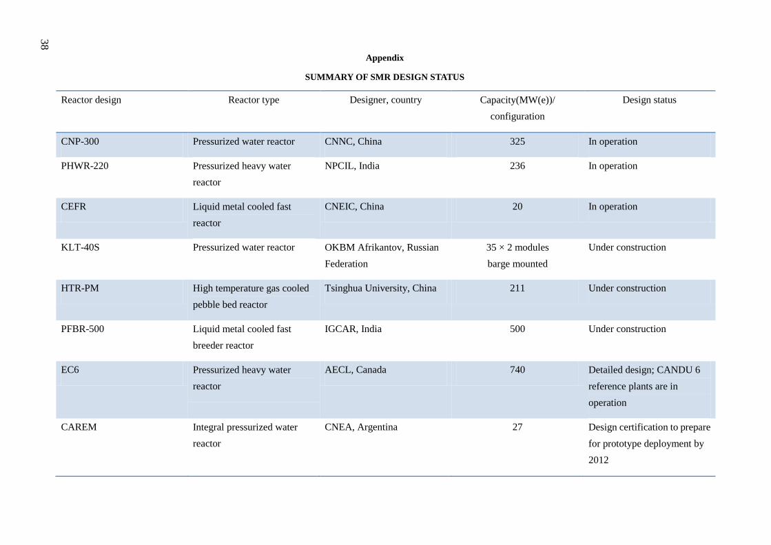
38
Appendix
SUMMARY OF SMR DESIGN STATUS
Reactor design Reactor type Designer, country Capacity(MW(e))/
configuration
Design status
CNP-300 Pressurized water reactor CNNC, China 325 In operation
PHWR-220 Pressurized heavy water
reactor
NPCIL, India 236 In operation
CEFR Liquid metal cooled fast
reactor
CNEIC, China 20 In operation
KLT-40S Pressurized water reactor OKBM Afrikantov, Russian
Federation
35 × 2 modules
barge mounted
Under construction
HTR-PM High temperature gas cooled
pebble bed reactor
Tsinghua University, China 211 Under construction
PFBR-500 Liquid metal cooled fast
breeder reactor
IGCAR, India 500 Under construction
EC6 Pressurized heavy water
reactor
AECL, Canada 740 Detailed design; CANDU 6
reference plants are in
operation
CAREM Integral pressurized water
reactor
CNEA, Argentina 27 Design certification to prepare
for prototype deployment by
2012
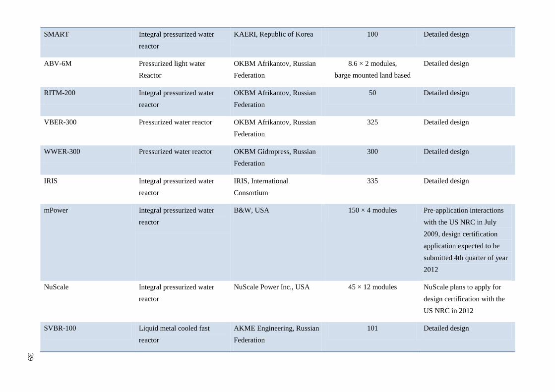
39
SMART Integral pressurized water
reactor
KAERI, Republic of Korea 100 Detailed design
ABV-6M Pressurized light water
Reactor
OKBM Afrikantov, Russian
Federation
8.6 × 2 modules,
barge mounted land based
Detailed design
RITM-200 Integral pressurized water
reactor
OKBM Afrikantov, Russian
Federation
50 Detailed design
VBER-300 Pressurized water reactor OKBM Afrikantov, Russian
Federation
325 Detailed design
WWER-300 Pressurized water reactor OKBM Gidropress, Russian
Federation
300 Detailed design
IRIS Integral pressurized water
reactor
IRIS, International
Consortium
335 Detailed design
mPower Integral pressurized water
reactor
B&W, USA 150 × 4 modules Pre-application interactions
with the US NRC in July
2009, design certification
application expected to be
submitted 4th quarter of year
2012
NuScale Integral pressurized water
reactor
NuScale Power Inc., USA 45 × 12 modules NuScale plans to apply for
design certification with the
US NRC in 2012
SVBR-100 Liquid metal cooled fast
reactor
AKME Engineering, Russian
Federation
101 Detailed design
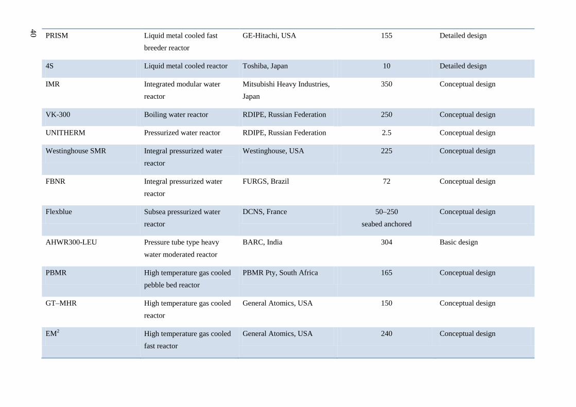
40
PRISM Liquid metal cooled fast
breeder reactor
GE-Hitachi, USA 155 Detailed design
4S Liquid metal cooled reactor Toshiba, Japan 10 Detailed design
IMR Integrated modular water
reactor
Mitsubishi Heavy Industries,
Japan
350 Conceptual design
VK-300 Boiling water reactor RDIPE, Russian Federation 250 Conceptual design
UNITHERM Pressurized water reactor RDIPE, Russian Federation 2.5 Conceptual design
Westinghouse SMR Integral pressurized water
reactor
Westinghouse, USA 225 Conceptual design
FBNR Integral pressurized water
reactor
FURGS, Brazil 72 Conceptual design
Flexblue Subsea pressurized water
reactor
DCNS, France 50–250
seabed anchored
Conceptual design
AHWR300-LEU Pressure tube type heavy
water moderated reactor
BARC, India 304 Basic design
PBMR High temperature gas cooled
pebble bed reactor
PBMR Pty, South Africa 165 Conceptual design
GT–MHR High temperature gas cooled
reactor
General Atomics, USA 150 Conceptual design
EM2 High temperature gas cooled
fast reactor
General Atomics, USA 240 Conceptual design
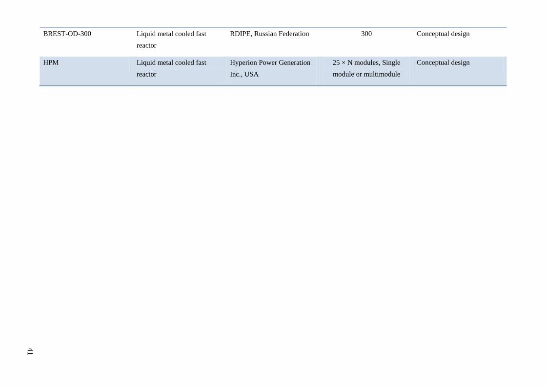
41
BREST-OD-300 Liquid metal cooled fast
reactor
RDIPE, Russian Federation 300 Conceptual design
HPM Liquid metal cooled fast
reactor
Hyperion Power Generation
Inc., USA
25 × N modules, Single
module or multimodule
Conceptual design
42
REFERENCES
[1] INTERNATIONAL ATOMIC ENERGY AGENCY, Status of innovative small and medium sized
reactor designs 2005: Reactors with conventional refuelling schemes, IAEA-TECDOC-1485, IAEA,
Vienna (2006).
[2] PAKISTAN ATOMIC ENERGY COMMISSION, Chashma Nuclear Power Plant-1 (CHASNUPP-1),
PAEC, Islamabad (2011), http://www.paec.gov.pk/chasnupp1/index.htm
[3] JOINT STOCK COMPANY ‘AFRIKANTOV EXPERIMENTAL DESIGN BUREAU FOR
MECHANICAL ENGINEERING’, Small Power Plants with ABV–6M Reactors, JSC ‘OKBM
Afrikantov’, Nizhny Novgorod (1999), http://www.okbm.nnov.ru/images/pdf/eng/abv_eng.pdf
[4] INTERNATIONAL ATOMIC ENERGY AGENCY, Status of small reactor designs without on-site
refuelling, IAEA-TECDOC-1536, IAEA, Vienna (2007).
[5] BABCOCK & WILCOX NUCLEAR ENERGY, INC., Generation mPower™, B&W, Charlotte, NC
(2011), http://www.babcock.com/products/modular_nuclear/generation_mpower.html
[6] TSINGHUA UNIVERSITY INSTITUTE OF NUCLEAR AND NEW ENERGY TECHNOLOGY,
HTR–PM, Beijing (2010), http://www.tsinghua.edu.cn/publish/ineten/5695/index.html
[7] GENERAL ATOMICS AND AFFILIATED COMPANIES, EM2™
Energy Multiplier Module, General
Atomics, San Diego, CA (2010), http://www.ga.com/energy/em2/
[8] INTERNATIONAL ATOMIC ENERGY AGENCY, Status of fast reactor research and technology
development, IAEA, Vienna (in preparation).
[9] SUBRAMANIAN, T.S., Prototype Fast Breeder Reactor ‘has independent safety mechanisms', The
Hindu (30 April 2011).
[10] INTERNATIONAL ATOMIC ENERGY AGENCY, Power reactors and sub-critical blanket systems
with lead and lead–bismuth as coolant and/or target material, IAEA-TECDOC-1348, IAEA, Vienna
(2006).
[11] GE HITACHI NUCLEAR ENERGY, PRISM Technology Update, GEH, Wilmington, NC (2009),
http://www.ge-energy.com/content/multimedia/_files/downloads/dataform_2053733743_2809794.pdf
[12] NUCLEAR REGULATORY COMMISSION, Preapplication Safety Evaluation Report for the
Power Reactor Innovative Small Module (PRISM) Liquid–Metal Reactor, Rep. NUREG–1368, NRC,
Washington DC (1994).
[13] HYPERION POWER GENERATION, A New Paradigm for Power Generation, Hyperion Power
Generation, Santa Fe, NM (2011), http://www.hyperionpowergeneration.com/product.html