
Status of Hybrid Wing Body Community Noise Assessments · Status of Hybrid Wing Body Community...
26
National Aeronautics and Space Administration Status of Hybrid Wing Body Community Noise Assessments Russell H. Thomas, Casey L. Burley, and Erik D. Olson NASA Langley Research Center, Hampton, VA USA Presented at the AIAA Aerospace Sciences Meeting Special ERA Session Orlando, Florida January 6, 2011 www.nasa.gov 1
Transcript of Status of Hybrid Wing Body Community Noise Assessments · Status of Hybrid Wing Body Community...
National Aeronautics and Space Administration
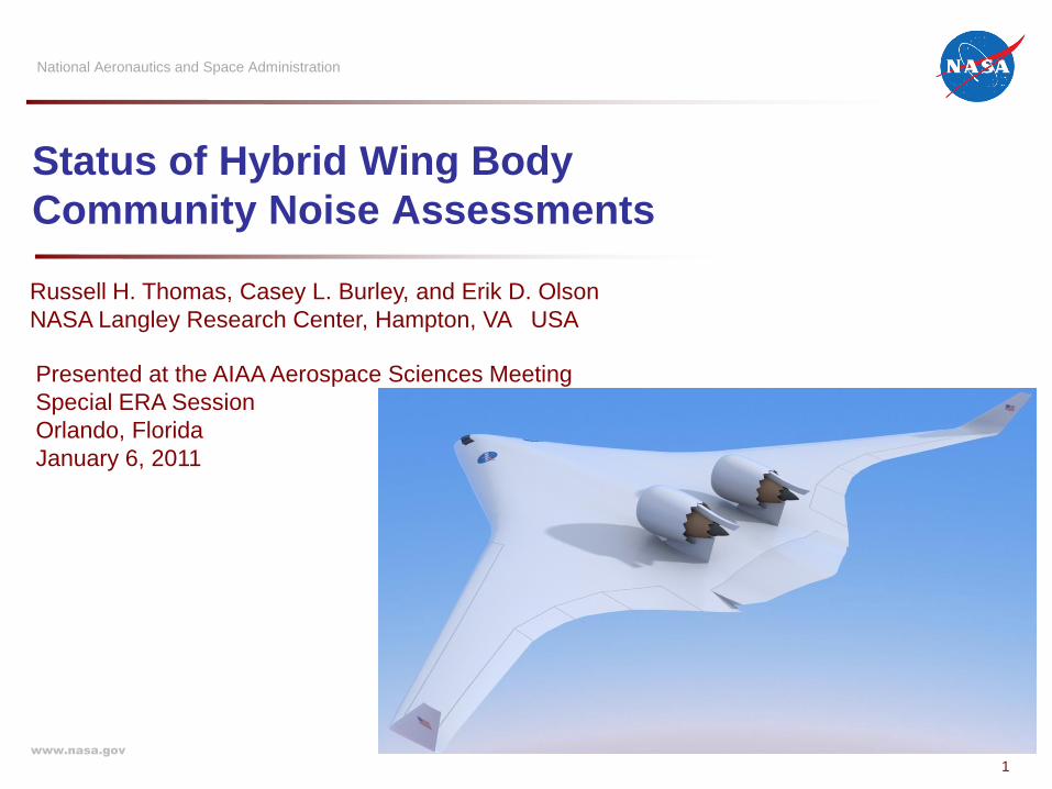
Status of Hybrid Wing Body
Community Noise Assessments
Russell H. Thomas, Casey L. Burley, and Erik D. Olson
NASA Langley Research Center, Hampton, VA USA
Presented at the AIAA Aerospace Sciences Meeting
Special ERA Session
Orlando, Florida
January 6, 2011
www.nasa.gov
1
Introduction
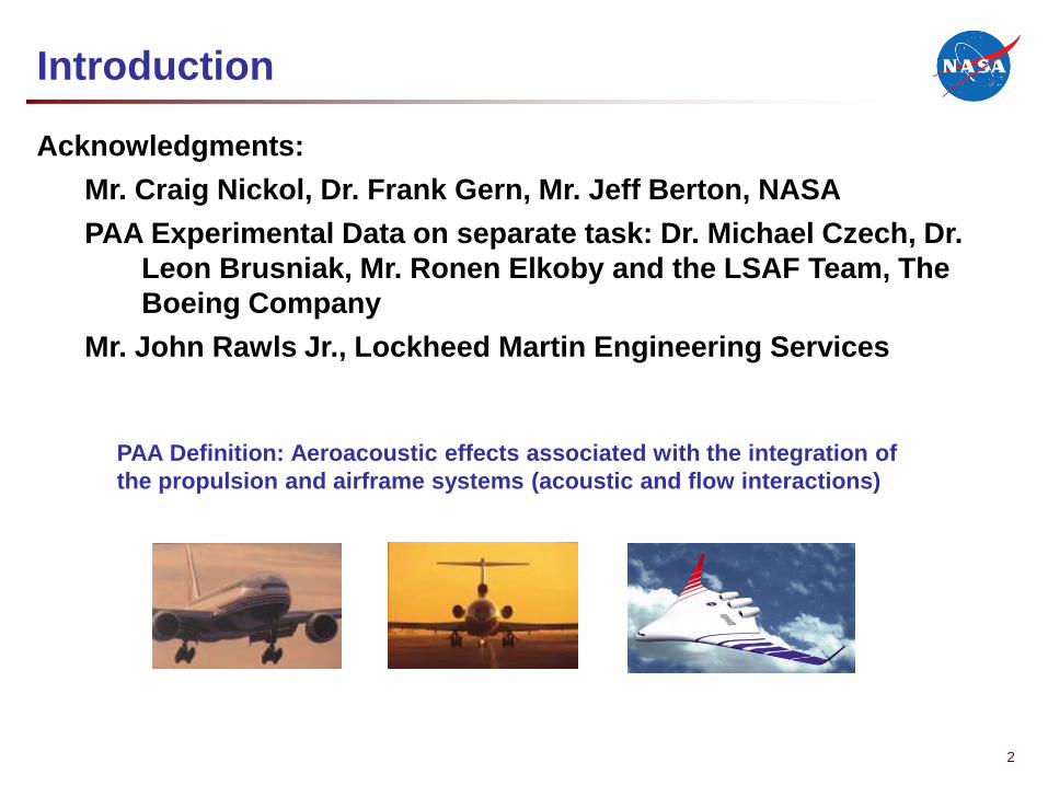
Acknowledgments:
Mr. Craig Nickol, Dr. Frank Gern, Mr. Jeff Berton, NASA
PAA Experimental Data on separate task: Dr. Michael Czech, Dr.
Leon Brusniak, Mr. Ronen Elkoby and the LSAF Team, The
Boeing Company
Mr. John Rawls Jr., Lockheed Martin Engineering Services
PAA Definition: Aeroacoustic effects associated with the integration of
the propulsion and airframe systems (acoustic and flow interactions)
2
Outline
• NASA N+2 Noise Goal Roadmap
HWB with BPR 7 Turbofan (ref: AIAA 2010-3913 Thomas, Burley, and Olson)•
• Assessment Process Including PAA Experiment
HWB Configurations
System Noise Impacts
Summary & Future Directions – HWB with UHB Turbofan
•
•
•
• Current Study In Progress – HWB with Open Rotor
• LSAF PAA Experiment
Assessment Process•
• Summary
3
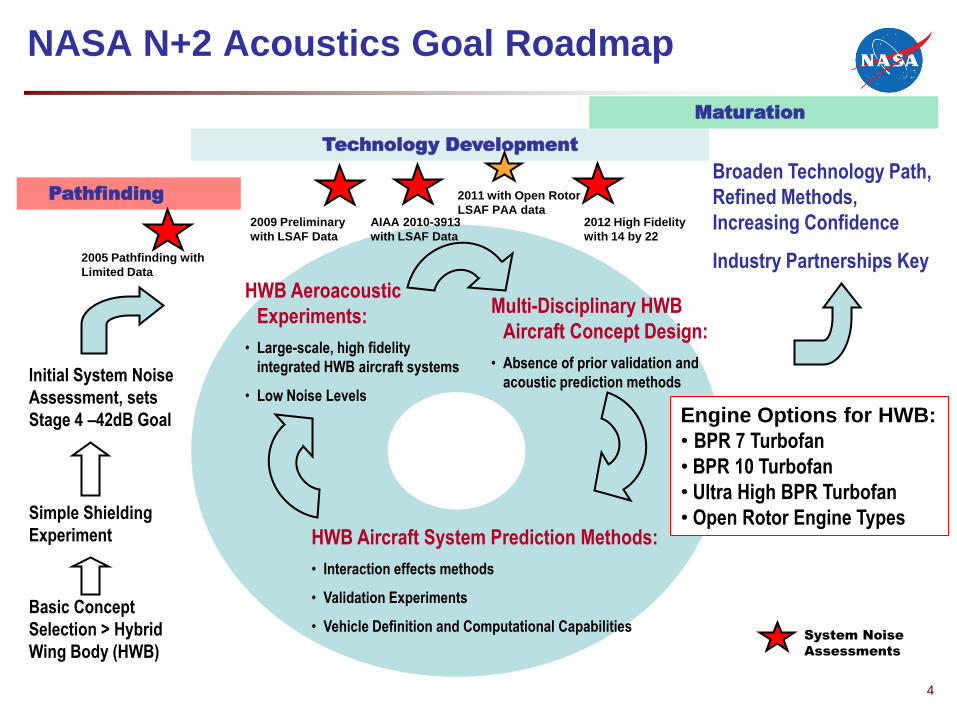
NASA N+2 Acoustics Goal Roadmap
Initial System Noise
Assessment, sets
Stage 4 –42dB Goal
Simple Shielding
Experiment
Basic Concept
Selection > Hybrid
Wing Body (HWB)
Broaden Technology Path,
Refined Methods,
Increasing Confidence
Industry Partnerships Key
Pathfinding
Technology Development
Maturation
HWB Aeroacoustic
Experiments:
• Large-scale, high fidelity
integrated HWB aircraft systems
• Low Noise Levels
Multi-Disciplinary HWB
Aircraft Concept Design:
• Absence of prior validation and
acoustic prediction methods
HWB Aircraft System Prediction Methods:
• Interaction effects methods
• Validation Experiments
• Vehicle Definition and Computational Capabilities
2009 Preliminary
with LSAF Data
4
System Noise
Assessments
AIAA 2010-3913
with LSAF Data
2005 Pathfinding with
Limited Data
2012 High Fidelity
with 14 by 22
2011 with Open Rotor
LSAF PAA data
Engine Options for HWB:
• BPR 7 Turbofan
• BPR 10 Turbofan
• Ultra High BPR Turbofan
• Open Rotor Engine Types
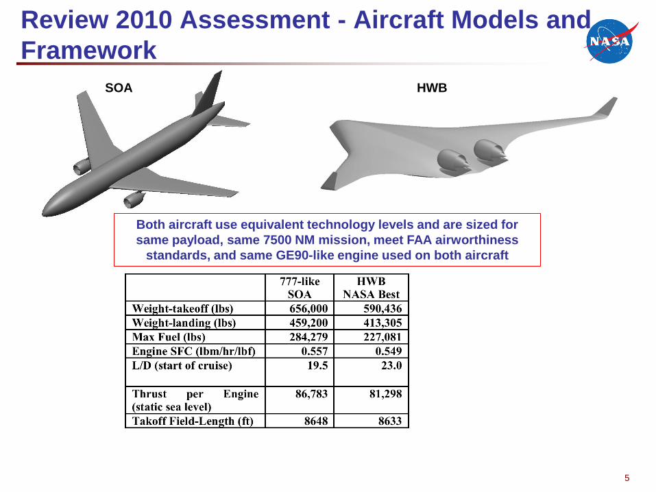
Review 2010 Assessment - Aircraft Models and
Framework
Both aircraft use equivalent technology levels and are sized for
same payload, same 7500 NM mission, meet FAA airworthiness
standards, and same GE90-like engine used on both aircraft
SOA HWB
5

Aircraft System Noise Prediction Method
• NASA Aircraft Noise Prediction Program (ANOPP-Lv 27)
• SOA and HWB flight definition from FLOPS
GE90-like relative engine noise sources match data (ref. Gliebe, 2003)
Total SOA prediction calibrated to match EPNL data for this aircraft
•
•
ANOPP
FLight OPtimization System (FLOPS)Aircraft Flight Definition
Numerical Propulsion System
Simulation (NPSS)
Source Noise
Jet: ST2JET
Fan: Boeing method
Duct Treatment: GE
Core: SAE
Airframe: Boeing, Fink (t.e.)
Experimental
Data from
LSAF (ref AIAA
2010-3912)
PAA Effects
Propagation & Noise Metrics
EPNL predicted at FAR 36 locations6
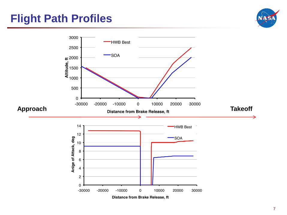
Flight Path Profiles
7
Approach Takeoff
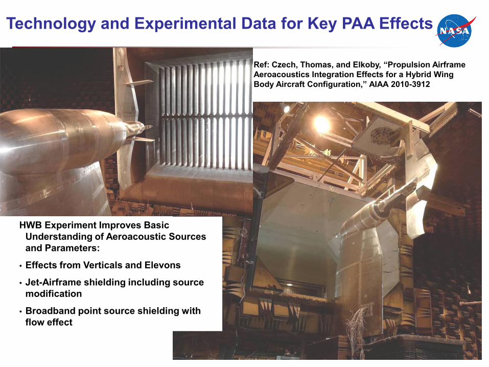
Technology and Experimental Data for Key PAA Effects
•
HWB Experiment Improves Basic Understanding of Aeroacoustic Sources and Parameters:
Effects from Verticals and Elevons
Jet-Airframe shielding including source modification
Broadband point source shielding with flow effect
•
•
Ref: Czech, Thomas, and Elkoby, “Propulsion Airframe Aeroacoustics Integration Effects for a Hybrid Wing Body Aircraft Configuration,” AIAA 2010-3912
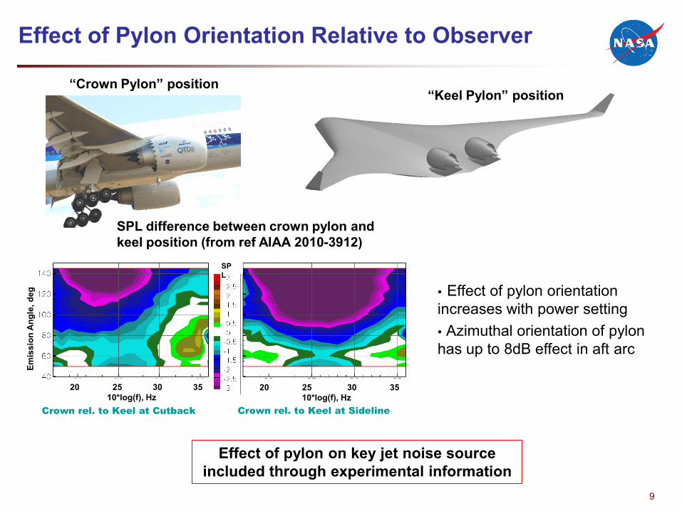
Effect of Pylon Orientation Relative to Observer
“Crown Pylon” position“Keel Pylon” position
SPL difference between crown pylon and keel position (from ref AIAA 2010-3912)
• Effect of pylon orientation increases with power setting• Azimuthal orientation of pylon has up to 8dB effect in aft arc
Effect of pylon on key jet noise source included through experimental information
Crown rel. to Keel at Cutback Crown rel. to Keel at Sideline
20 25 30 3510*log(f), Hz
20 25 30 3510*log(f), Hz
Emis
sion
Ang
le, d
eg
SPL
9
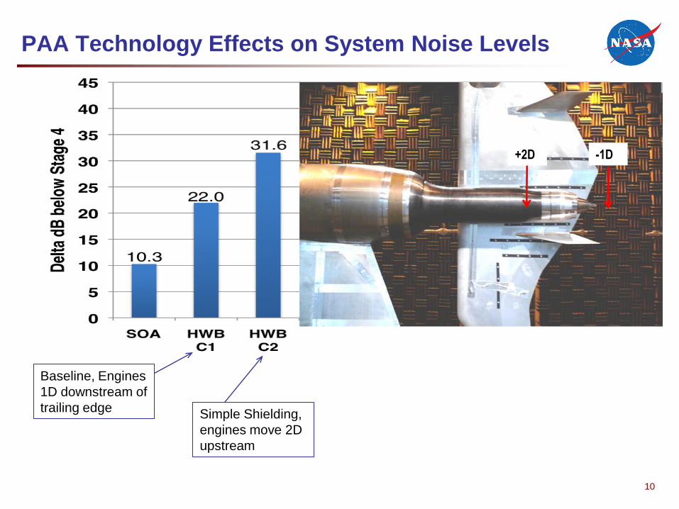
PAA Technology Effects on System Noise Levels
+2D -1D
Baseline, Engines
1D downstream of
trailing edgeSimple Shielding,
engines move 2D
upstream
10
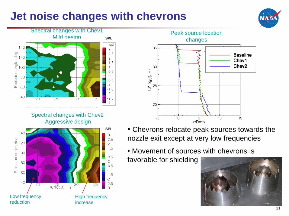
Jet noise changes with chevronsSpectral changes with Chev1
Mild designPeak source location
changes
• Chevrons relocate peak sources towards th
nozzle exit except at very low frequencies
• Movement of sources with chevrons is
favorable for shielding
e
Spectral changes with Chev2
Aggressive design
High frequency
increase
Low frequency
reduction
SPL
SPL
11
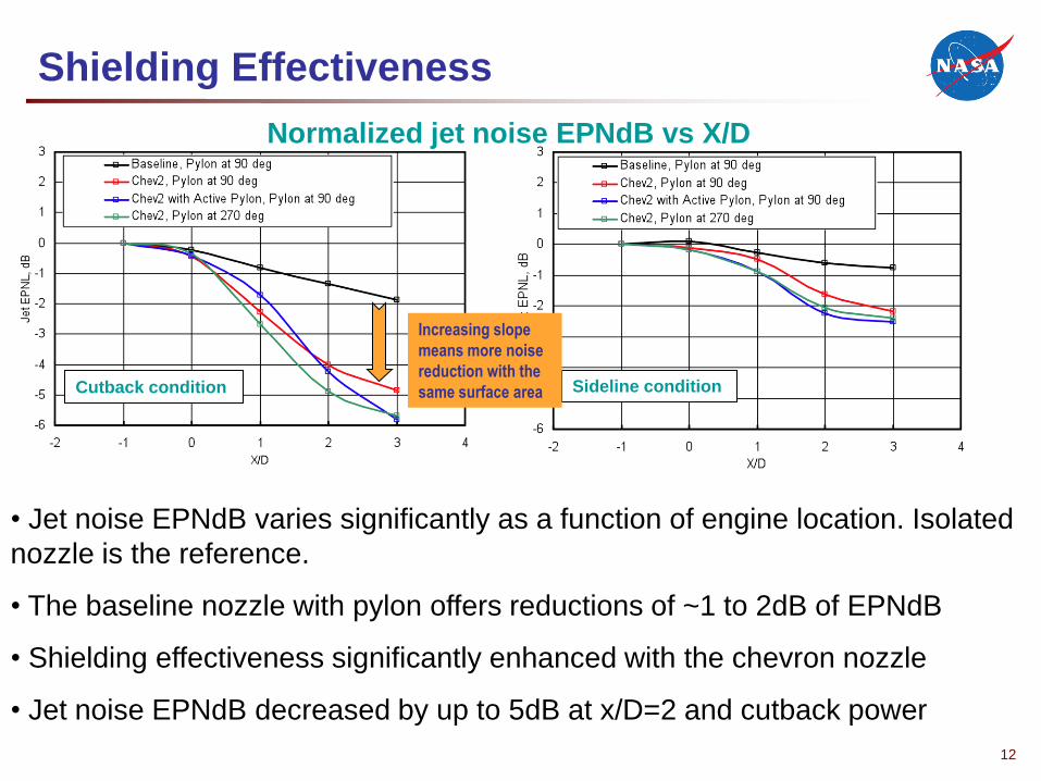
Shielding Effectiveness
Normalized jet noise EPNdB vs X/D
Sideline conditionCutback condition
• Jet noise EPNdB varies significantly as a function of engine location. Isol
nozzle is the reference.
• The baseline nozzle with pylon offers reductions of ~1 to 2dB of EPNdB
• Shielding effectiveness significantly enhanced with the chevron nozzle
• Jet noise EPNdB decreased by up to 5dB at x/D=2 and cutback power
ated
Increasing slope
means more noise
reduction with the
same surface area
12
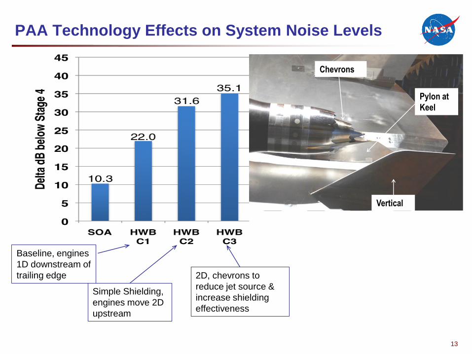
PAA Technology Effects on System Noise Levels
Baseline, engines
1D downstream of
trailing edge
Simple Shielding,
engines move 2D
upstream
2D, chevrons to
reduce jet source &
increase shielding
effectiveness
Vertical
Pylon at
Keel
Chevrons
13
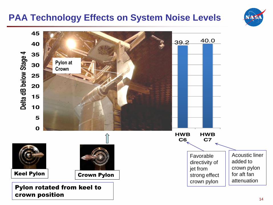
PAA Technology Effects on System Noise Levels
Favorable
directivity of
jet from
strong effect
crown pylon
Acoustic liner
added to
crown pylon
for aft fan
attenuation
Pylon at
Crown
Keel PylonCrown Pylon
Pylon rotated from keel to
crown position14
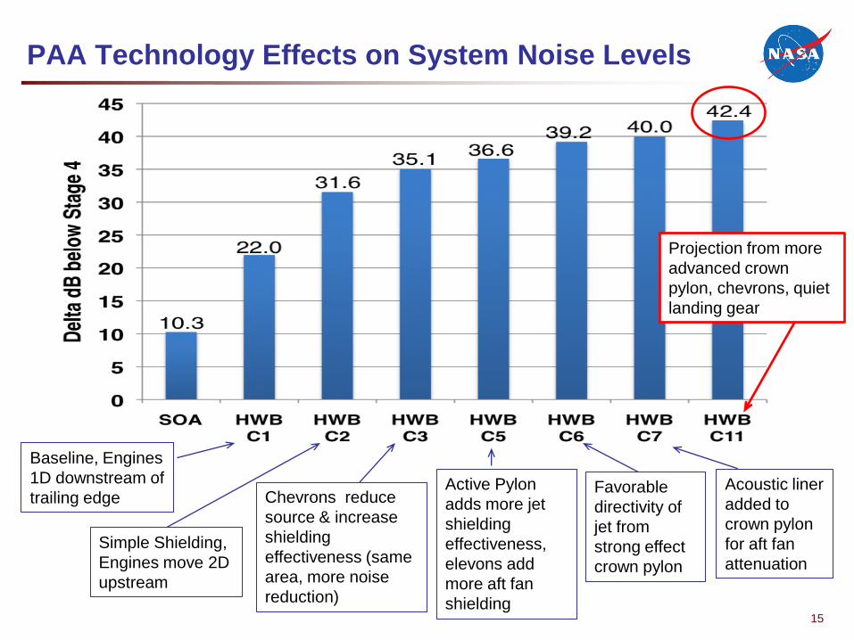
PAA Technology Effects on System Noise Levels
Baseline, Engines
1D downstream of
trailing edge
Simple Shielding,
Engines move 2D
upstream
Chevrons reduce
source & increase
shielding
effectiveness (same
area, more noise
reduction)
Active Pylon
adds more jet
shielding
effectiveness,
elevons add
more aft fan
shielding
Favorable
directivity of
jet from
strong effect
crown pylon
Acoustic liner
added to
crown pylon
for aft fan
attenuation
Projection from more
advanced crown
pylon, chevrons, quiet
landing gear
15
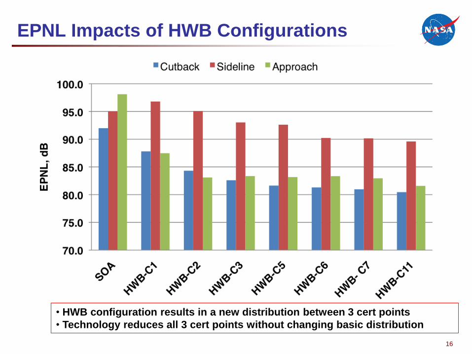
EPNL Impacts of HWB Configurations
• HWB configuration results in a new distribution between 3 cert points
Technology reduces all 3 cert points without changing basic distribution•
16
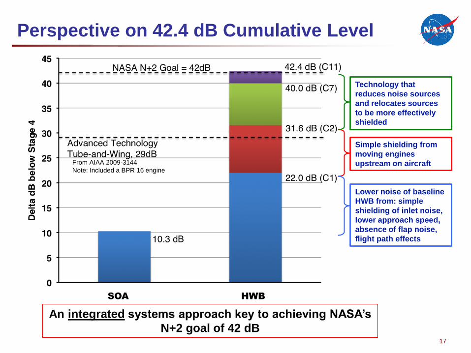
Perspective on 42.4 dB Cumulative Level
From AIAA 2009-3144
Note: Included a BPR 16 engine
SOA HWB
Technology that
reduces noise sources
and relocates sources
to be more effectively
shielded
Simple shielding from
moving engines
upstream on aircraft
Lower noise of baseline
HWB from: simple
shielding of inlet noise,
lower approach speed,
absence of flap noise,
flight path effects
An integrated systems approach key to achieving NASA’s
N+2 goal of 42 dB17

Sound Exposure Level (SEL) Contour
SOA
HWB
Impact is a 66% reduction in ground area
For a simulated
certification procedure
(FAR 36) takeoff and
landing
18
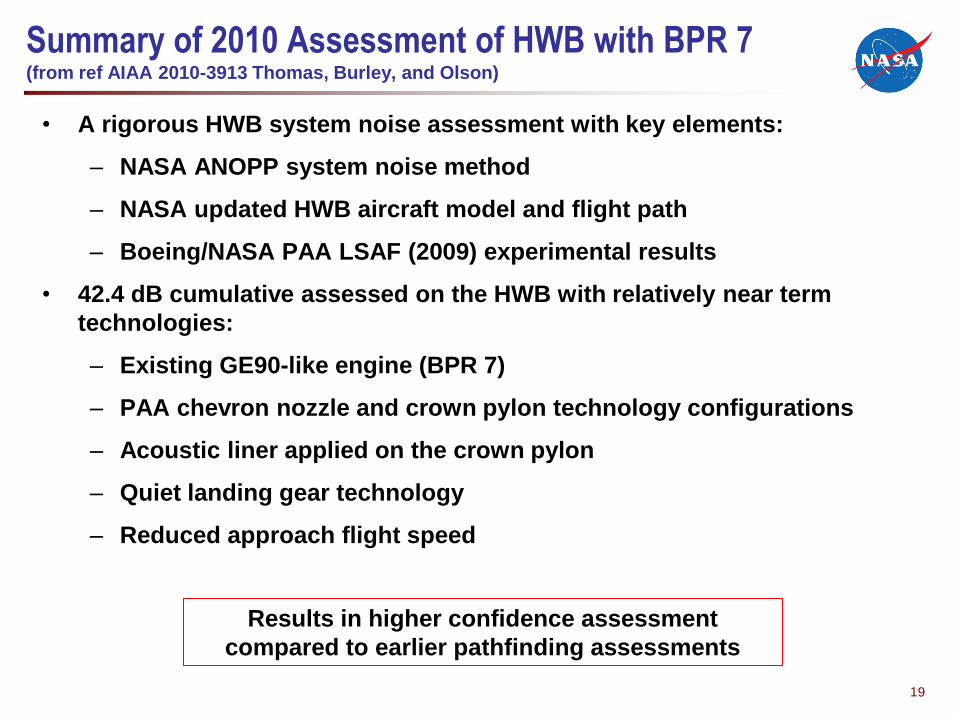
Summary of 2010 Assessment of HWB with BPR 7 (from ref AIAA 2010-3913 Thomas, Burley, and Olson)
• A rigorous HWB system noise assessment with key elements:
– NASA ANOPP system noise method
NASA updated HWB aircraft model and flight path
Boeing/NASA PAA LSAF (2009) experimental results
–
–
• 42.4 dB cumulative assessed on the HWB with relatively near term
technologies:
– Existing GE90-like engine (BPR 7)
PAA chevron nozzle and crown pylon technology configurations
Acoustic liner applied on the crown pylon
Quiet landing gear technology
Reduced approach flight speed
–
–
–
–
Results in higher confidence assessment
compared to earlier pathfinding assessments
19
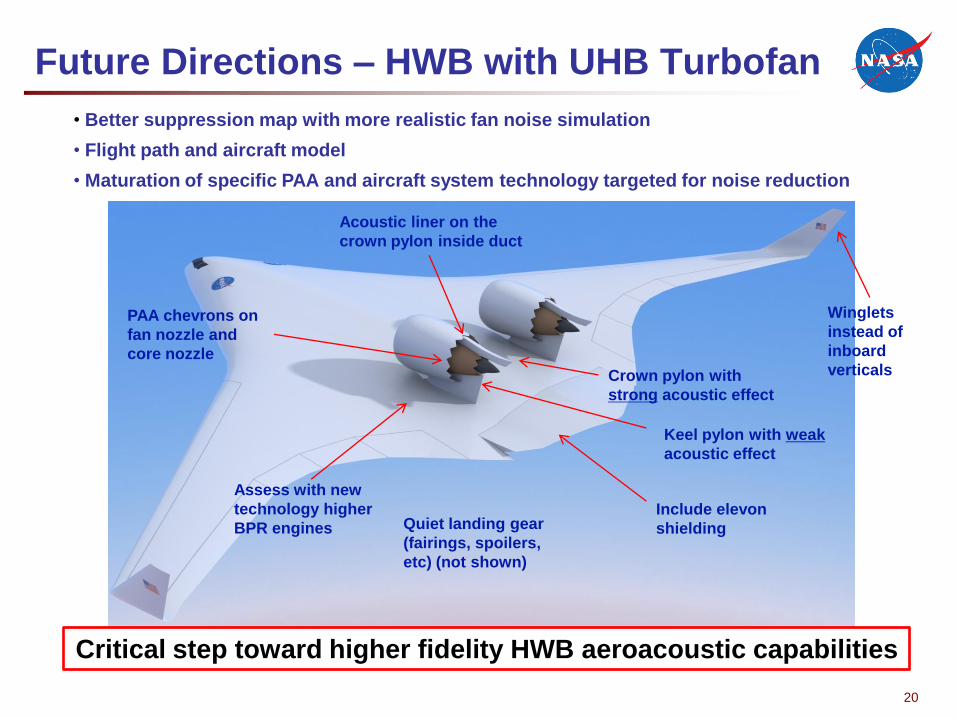
Future Directions – HWB with UHB Turbofan
Better suppression map with more realistic fan noise simulation
Flight path and aircraft model
Maturation of specific PAA and aircraft system technology targeted for noise reduction
Assess with new
technology higher
BPR engines
Keel pylon with weak
acoustic effect
Crown pylon with
strong acoustic effect
Acoustic liner on the
crown pylon inside duct
Winglets
instead of
inboard
verticals
PAA chevrons on
fan nozzle and
core nozzle
Quiet landing gear
(fairings, spoilers,
etc) (not shown)
•
•
•
Include elevon
shielding
Critical step toward higher fidelity HWB aeroacoustic capabilities
20
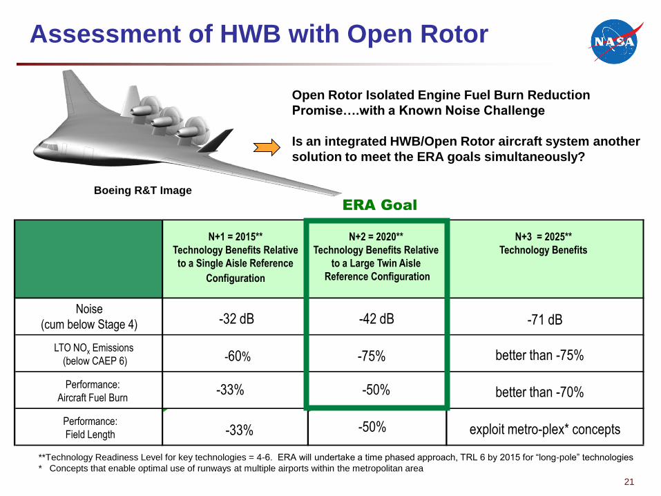
Assessment of HWB with Open Rotor
Boeing R&T Image
Open Rotor Isolated Engine Fuel Burn Reduction
Promise….with a Known Noise Challenge
Is an integrated HWB/Open Rotor aircraft system another
solution to meet the ERA goals simultaneously?
ERA Goal
N+1 = 2015**
Technology Benefits Relative
to a Single Aisle Reference
Configuration
N+2 = 2020**
Technology Benefits Relative
to a Large Twin Aisle
Reference Configuration
N+3 = 2025**
Technology Benefits
Noise
(cum below Stage 4) -32 dB -42 dB -71 dB
LTO NO Emissionsx
(below CAEP 6) -60% -75% better than -75%
Performance:
Aircraft Fuel Burn-33% -50% better than -70%
exploit metro-plex* conceptsPerformance:
Field Length -33% -50%
**Technology Readiness Level for key technologies = 4-6. ERA will undertake a time phased approach, TRL 6 by 2015 for “long-pole” technologies
* Concepts that enable optimal use of runways at multiple airports within the metropolitan area
21
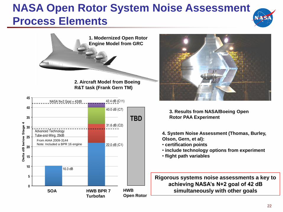
NASA Open Rotor System Noise Assessment
Process Elements
From AIAA 2009-3144
Note: Included a BPR 16 engine
SOA HWB BPR 7
Turbofan
HWB
Open Rotor
TBD
1. Modernized Open Rotor
Engine Model from GRC
2. Aircraft Model from Boeing
R&T task (Frank Gern TM)
•
•
•
3. Results from NASA/Boeing Open
Rotor PAA Experiment
4. System Noise Assessment (Thomas, Burley,
Olson, Gern, et al):
certification points
include technology options from experiment
flight path variables
Rigorous systems noise assessments a key to
achieving NASA’s N+2 goal of 42 dB
simultaneously with other goals
22
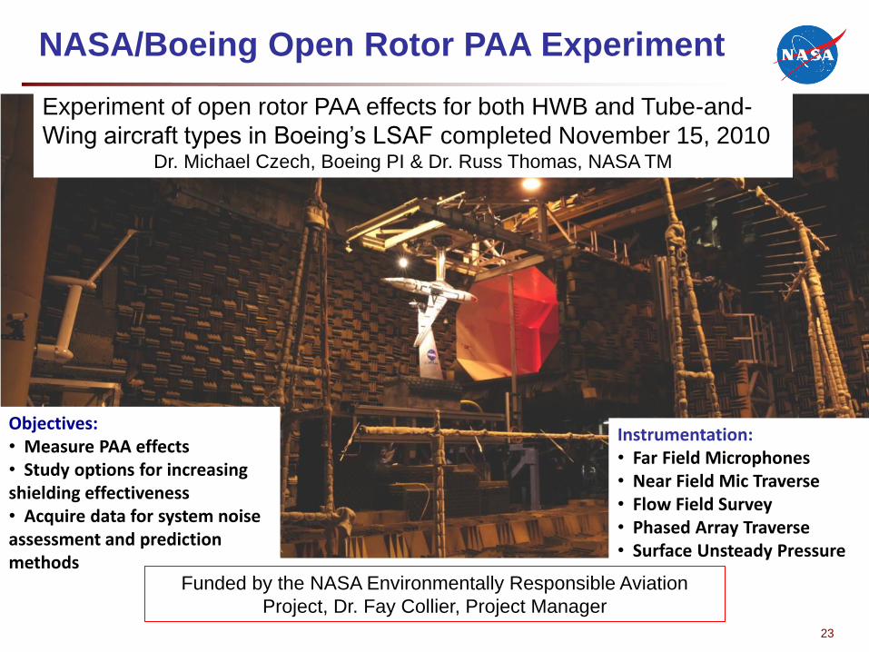
NASA/Boeing Open Rotor PAA Experiment
Experiment of open rotor PAA effects for both HWB and Tube-and-
Wing aircraft types in Boeing’s LSAF completed November 15, 2010Dr. Michael Czech, Boeing PI & Dr. Russ Thomas, NASA TM
Objectives:• Measure PAA effects• Study options for increasing shielding effectiveness• Acquire data for system noise assessment and prediction methods
Instrumentation:• Far Field Microphones
Near Field Mic TraverseFlow Field SurveyPhased Array TraverseSurface Unsteady Pressure
•
•
•
•
Funded by the NASA Environmentally Responsible Aviation
Project, Dr. Fay Collier, Project Manager
23
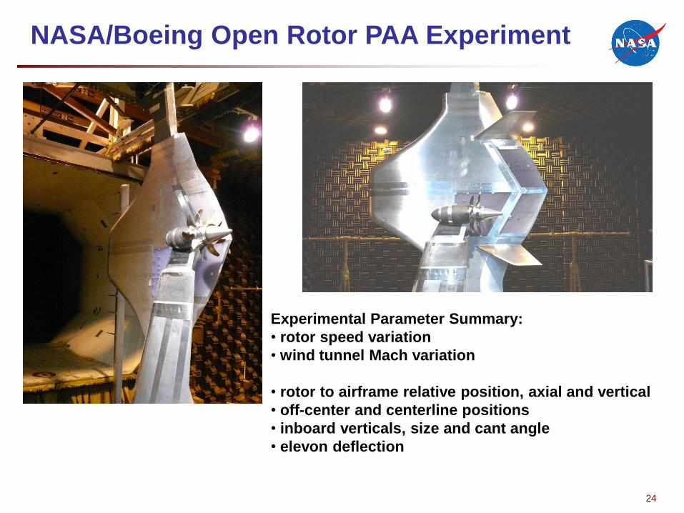
NASA/Boeing Open Rotor PAA Experiment
•
•
•
•
•
•
Experimental Parameter Summary:
rotor speed variation
wind tunnel Mach variation
rotor to airframe relative position, axial and vertical
off-center and centerline positions
inboard verticals, size and cant angle
elevon deflection
24
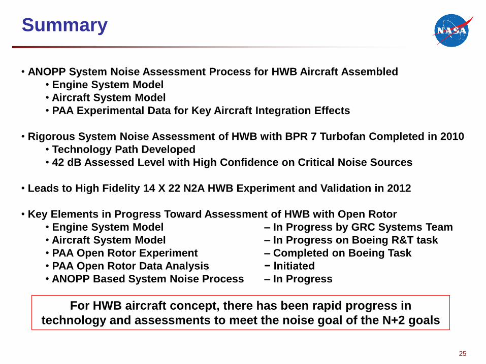
Summary
• ANOPP System Noise Assessment Process for HWB Aircraft Assembled
• Engine System Model
Aircraft System Model
PAA Experimental Data for Key Aircraft Integration Effects
•
•
• Rigorous System Noise Assessment of HWB with BPR 7 Turbofan Completed in 2010
• Technology Path Developed
42 dB Assessed Level with High Confidence on Critical Noise Sources•
• Leads to High Fidelity 14 X 22 N2A HWB Experiment and Validation in 2012
Key Elements in Progress Toward Assessment of HWB with Open Rotor•
• Engine System Model
Aircraft System Model
PAA Open Rotor Experiment
PAA Open Rotor Data Analysis
ANOPP Based System Noise Process
– In Progress by GRC Systems Team
In Progress on Boeing R&T task
Completed on Boeing Task
Initiated
In Progress
• –
• –
• −
• –
For HWB aircraft concept, there has been rapid progress in
technology and assessments to meet the noise goal of the N+2 goals
25

26Your Title Here
26


