STATUS IN WALES 2022 Sup1.pdf · [email protected] or telephone 029 2031 5512 ... STATUS IN...
53
For queries on the status of this document contact [email protected] or telephone 029 2031 5512 Status Note amended March 2013 HEALTH TECHNICAL MEMORANDUM 2022 SUPPLEMENT 1 Medical gas pipeline systems Supplement 1: Dental compressed air and vacuum systems 2003 STATUS IN WALES APPLIES This document replaced HTM 2022 Supplement 1 Medical gas pipeline systems Dental compressed air and vacuum systems 1996
Transcript of STATUS IN WALES 2022 Sup1.pdf · [email protected] or telephone 029 2031 5512 ... STATUS IN...

For queries on the status of this document contact [email protected] or telephone 029 2031 5512
Status Note amended March 2013
HEALTH TECHNICAL MEMORANDUM 2022 SUPPLEMENT 1
Medical gas pipeline systems
Supplement 1: Dental compressed air and vacuum systems
2003
STATUS IN WALES
APPLIES
This document replaced HTM 2022 Supplement 1
Medical gas pipeline systems Dental compressed air and vacuum systems
1996


Denta
l com
pre
ssed a
ir and va
cuum
syste
ms A
N U
PD
AT
E O
F H
TM
2022 SU
PP
LE
ME
NT
1
Dental compressed air andvacuum systems
AN UPDATE OF HTM 2022 – SUPPLEMENT 1

Dental compressed air andvacuum systems
AN UPDATE OF HTM 2022 – SUPPLEMENT 1
London: The Stationery Office

Published by TSO (The Stationery Office) and available from:
Onlinewww.tso.co.uk/bookshop
Mail, Telephone, Fax & E-mailTSOPO Box 29, Norwich NR3 1GNTelephone orders/General enquiries 0870 600 5522Fax orders 0870 600 5533E-mail [email protected]
TSO Shops123 Kingsway, London WC2B 6PQ020 7242 6393 Fax 020 7242 639468–69 Bull Street, Birmingham B4 6AD0121 236 9696 Fax 0121 236 96999–21 Princess Street, Manchester M60 8AS0161 834 7201 Fax 0161 833 063416 Arthur Street, Belfast BT1 4GD028 9023 8451 Fax 028 9023 540118–19 High Street, Cardiff CF10 1PT029 2039 5548 Fax 029 2038 434771 Lothian Road, Edinburgh EH3 9AZ0870 606 5566 Fax 0870 606 5588
TSO Accredited Agents(see Yellow Pages)
and through good booksellers
© Crown copyright 2003
Published with the permission of NHS Estates, an Executive Agency of the Department of Health, on behalf of the Controller of Her Majesty’s StationeryOffice.
Applications for reproduction should be made in writing to:
The Copyright Unit,Her Majesty’s Stationery Office,St Clements House,2–16 Colegate,Norwich NR3 1BQ.
ISBN 0-11-322478-8
Second edition 2003First edition published 1996
Printed in the United Kingdom for The Stationery Office

GENERAL
This Supplement provides advice and guidance on thespecific requirements for compressed air and vacuumsystems for use in dental hospitals, dental teachingschools, clinics and surgeries and primary care trusts(PCTs).
The Supplement should be followed for all newinstallations and refurbishment; existing installationsshould be assessed for compliance with thisSupplement. Where necessary, a plan for upgrading theexisting systems should be prepared, taking intoaccount the priority for patient and staff safety andstatutory requirements which may have becomeeffective subsequent to any existing installations.Owners, occupiers, general managers and chiefexecutives should ensure that the premises for whichthey have responsibility and any activities carried outtherein comply with these statutory requirements. Thiscompliance is obligatory.
Managers will need to liaise with dental and estatescolleagues and take account of other guidancepublished by the Department of Health to assess thesystem for technical shortcomings.
The guidance given in HTM 2022 should generally befollowed for these systems and plant accommodation,except where modified in this Supplement.
This Supplement supersedes ‘HTM 2022 – Supplement1: Dental compressed air and vacuum systems’ firstpublished in November 1996.
USE OF MEDICAL GAS SYSTEMS
Dental hospitals, clinics and surgeries requirecompressed air to power dental instruments and avacuum system to remove detritus from the operationsite.
The performance requirements of dental compressed airand vacuum systems differ from those for medical airand vacuum, and they should be provided in addition tothe medical gas pipework systems (MGPS). To avoidconfusion they will be referred to as dental compressedair and vacuum systems (DAVS). Medical gas systemsshould not be used for dental purposes. However, itmay be possible to extend a surgical air system into a
dental department for dental surgical purposes,provided that the existing system is capable of meetingthe resulting increase in demand without detriment tothe performance of either system.
QUALITY REQUIREMENTS
Dental air is usually supplied via a compressor, whichshould be fitted with an air-intake filter and a post-compression filtration and dryer system. This ensuresthat the air is clean and dry, minimising the risk ofcontamination of the system by micro-organisms andimproving the efficiency of dental instruments.
• The dryer system should be capable of producing airwith an atmospheric dew-point not less than –20ºC.
• The filter system should provide dust filtration downto 1 µm with a DOP (aerosol) efficiency of not less than99.97% and bacteria filtration down to 0.01 µm with aDOP (aerosol) efficiency of not less than 99.9999%.
AIR COMPRESSORS
Wet and dirty air will eventually lead to damage andcorrosion of instruments. Oil-free compressors offer asimple, cost-effective solution to the problem of oilcontamination. However, for larger installations, thereare implications of higher capital costs and noise levels.
Whatever compressor system is used, the importance ofproperly conducted regular maintenance cannot beoverstressed. Filters should be changed at least annuallyand more frequently if recommended by themanufacturer.
PIPELINE MATERIALS
The pipework distribution system for dental air shouldbe of a material technically suited to the application.Copper and nylon are commonly used in pipework.
Dental vacuum and exhaust line materials should alsoreflect current technology, with particular attention givento minimising the harmful effects of any effluent whichpipework may carry. For example, copper pipe shouldnot be used for wet vacuum systems, as it will beattacked by dental amalgam compounds.
Executive summary

VACUUM EXHAUST FILTRATION
The exhaust from the vacuum system should be sitedoutside, away from air intakes, opening windows etc(preferably above roof level) and be clearly labelled. Abacteria filter with particle removal to 0.01 µm with aDOP (aerosol) test efficiency of not less than 99.9999%should be inserted in the system, preferably betweenpipework and vacuum pumps. Small systemsexhausting into the work area should have such a filterfitted to the pump exhaust.
WATER SUPPLIES
The design and installation of the surgery’s water supplymust take account of the Water Supply (Water Fittings)Regulations 1999, in particular the need to preventcontamination waste and undue consumption.
To prevent contamination of the sewerage drainagesystems, amalgam separators should be fitted to alldental vacuum systems.
ACCOMMODATION
Accommodation for dental compressor and vacuumpumps should be carefully controlled to preventoverheating of plant and contamination of dental airsupplies, or freezing of and subsequent damage todrying systems and vacuum plant
INSTALLATION, TESTING AND MAINTENANCE
Installation, testing and maintenance of these systemsshould be carried out by competent authorities, that is
companies certificated under BS EN ISO 9000 with adefined scope of expertise. The Quality AssuranceScheme 3720 1/206.1A for MGPS is currently underreview and will be revised to include dental installationsand maintenance of both MGPS and DAVS.
COSHH
In areas where anaesthetic agents are in use, particularattention should be paid to the requirements of theCOSHH Regulations 1999. However, it must beremembered that these Regulations also apply to manyother compounds used in dentistry.
OPERATIONAL POLICY
An operational policy covering the day-to-daymanagement and operation of the DAVS should bedevised. Its preparation will usually be the responsibilityof the senior partner/practice manager or the AuthorisedPerson (MGPS), if the latter has responsibility for theDAVS.
PATHOLOGY DEPARTMENTS
Separate installations should be provided for pathologydepartments.
CE MARKING
All new plant should be marked with the appropriate CEmark; plant which is not so marked should not beinstalled. It should be remembered, however, thatpresence of a CE mark is no guarantee of conformitywith relevant standards.
DENTAL COMPRESSED AIR AND VACUUM SYSTEMS: HTM 2022 – SUPPLEMENT 1

Geoffrey Dillow (Main author), Consultant, GeoffreyDillow and Associates
Darryn Kerr (Chairman) and Committee Members MikeRalph, Steve Goddard, David Peel, Alex Black,Mike Arrowsmith, Ian Fraser, Paul Jones, MedicalGas Association
Clive Shakesheff Site Investigations Technician, BristolCity Council
Clive Bray Director, Device Technology and Safety et al,Medical Devices Agency
Mike Ralph Plant Operations and MaintenanceManager, Great Ormond Street Children’s Hospital
Ian Cooper Senior Dental Officer et al, Dental Division,Department of Health
Steve Goddard Training Consultant, Knowledge Pool
Mike Arrowsmith Arrowsmith & Associates
Steve Bailey Managing Director, Cattani ESAM UKLimited
Richard Orton, Technical Services Manager, KaVoDental Ltd
David Robinson Sales Manager, DentalEZ DentalProducts (GB) Ltd
Peter Stanford Sales Director, Bambi Air CompressorsLtd
Lyndon Saul Director Medical Architectural Systems,Dräger Medical
Henry Hicks Europe, Middle East and Africa ExportSales Manager, Penlon/East Healthcare
Steve Parkinson R&D Manager, Hill-Rom MEDÆS
Andy Booth International pipeline systems designer,Hill-Rom MEDÆS
Lynn Woods Health and Safety Advisor, Lesley Derry,Head of Professional Services, British Dental Association
Ian Pope Managing Director, Durr Dental (Products) UKLtd
Siegfried Nafzger Product Management Equipment,Durr Dental Germany
Dr Frank Haines-Nutt (Chair), Paul Jones, IanBeaumont, Brian Midcalf, Ed Doyle et al, RegionalPharmaceutical Officers Quality Control Group (Medicalgases)
Steven Griffiths DEFRA
Richard Hurst Senior Account Executive, WRc-NSFLtd.
Dr M Thorpe General Dental Surgeon, Gateshead
Dr H Thorpe Community Dental Officer, North DurhamPCT
Staff Environment Agency, Exeter
Judith Reilly HM Inspector et al, Health & SafetyExecutive, Health Services Unit
Ian Beaumont, Director, Kay Witham, QA and AuditOfficer, Quality Control North West
Paul Jones, Ed Doyle, Richard Sutherland,Directors, Medical Gas Testing Services
Mike George Managing Director, Dentalair UK
Garry Meager Building Services Engineer, DefenceEstates
Russ Tebbs Director, Mossman–Tebbs Ltd
Lee Kingston, Special Waste Business DevelopmentManager, Envirodent Ltd
Brian Elliott Higher Professional Technical Officer,Estates Policy, Health Estates Northern Ireland
Jonathan Oakley Sales Engineer, Dominick HunterFiltration
M P Godden, Director, HVDS
Acknowledgements

Executive summaryAcknowledgements
1.0 Scope page 2
2.0 Management responsibilities andguidelines page 3
2.1 Compliance with statutory requirements2.3 Functional responsibilities2.9 Use of the MGPS permit-to-work system2.11 Operational policy2.13 Training2.16 Extent of systems and limitation of use
3.0 Dental compressed air systems page 5
3.1 Statutory obligations3.8 The need for high quality dental air3.13 Dental air quality standard3.15 Air treatment required to meet the standard3.16 Air intake and pre-compression filtration3.19 Compressor systems – siting3.29 Compressor systems – types and noise levels3.35 Post-compression air treatment3.49 Pipework system design3.72 Plant monitoring and alarm systems3.76 Emergency supplies
4.0 Dental vacuum systems page 13
4.1 System types4.10 Plant siting4.13 Plant types and noise4.19 Filtration4.30 Pipework system design4.49 Plant monitoring and alarm systems
5.0 Validation and verification page 18
5.1 General principles 5.3 Test gas for dental air systems engineering tests5.4 Test equipment for engineering tests5.8 Commissioning tests5.25 Tests following repairs/modifications5.28 Pharmaceutical testing
6.0 Maintenance of dental air andvacuum systems (DAVS) page 21
6.1 Standards6.3 Modifications – safety6.4 Insurance inspections6.5 Maintenance schedules
Appendix 1 Dental vacuum systems andamalgam separation page 22
Appendix 2 Water supply systems to dentaldepartments and practices page 24
Appendix 3 COSHH – anaesthetic agentsand other substances page 28
Appendix 4 Electricity supplies and firedetection systems page 30
Appendix 5 Sample document forcontrol of work on plant and pipeworksystems in dental practices page 31
Appendix 6 Operational policy guidelines page 32
Appendix 7 Glossary of terms page 33
References page 41
About NHS Estates guidance and publications page 44
1
Contents

1.1 This Supplement to HTM 2022 covers the design,installation, validation, verification, operationalmanagement and maintenance of compressed air andvacuum systems for use in dental hospitals (includingdental teaching schools), surgeries and clinics. Itsupersedes ‘HTM 2022 – Supplement 1: Dentalcompressed air and vacuum systems’ first published inNovember 1996.
1.2 Other guidance on the provision of medical gaspipework systems (MGPS) is also given in the HealthBuilding Notes. Guidance on COSHH requirements isgiven in the Health & Safety Commission’s HealthServices Advisory Committee publication ‘AnaestheticAgents: controlling exposure under COSHH’.
1.3 The guidance given in HTM 2022 should generallybe followed for these systems, except where modified inthis Supplement.
1.4 Dental compressed air and vacuum systems (DAVS)are installed to provide safe, convenient and cost-effective systems for dental staff at the point of use.Problems associated with portable cylinders and suctionsystems, particularly patient and staff safety, porterageand storage are reduced.
1.5 The guidance given in this Supplement should befollowed for all new installations andrefurbishment/extension.
1.6 The guidance given in this Supplement should beimplemented for patient and staff safety and to complywith statutory requirements. Existing installations shouldbe assessed for compliance with this Supplement.Where necessary, a plan for upgrading the existingsystems should be prepared, taking account of thepriority for patient and staff safety and compliance withstatutory requirements which may have come into effectafter any existing installations. Managers will need toliaise with dental and estates colleagues, equipmentmanufacturers and installers and heed other guidancepublished by theDepartment of Health (DoH) to assessthe system for technical shortcomings.
1.7 The requirements in respect of compliance withstatutory regulations apply to all premises where dentalprocedures are carried out, regardless of whether theyare NHS or private premises.
1.8 Wherever possible, the appropriate British orequivalent European or international standards shouldbe used.
DENTAL COMPRESSED AIR AND VACUUM SYSTEMS: HTM 2022 – SUPPLEMENT 1
2
1 Scope

COMPLIANCE WITH STATUTORYREQUIREMENTS
2.1 It is the responsibility of the owners and occupiersof premises, general managers and chief executives toensure that their premises and the activities carried outwithin those premises comply with all appropriatestatutory requirements, some of which are listed below:
• Management of Health and Safety at WorkRegulations 1999.
• Workplace (Health, Safety and Welfare) Regulations1992.
• Provision and Use of Work Equipment Regulations1998.
• Reporting of Injuries, Diseases and DangerousOccurrences Regulations (RIDDOR) 1995.
• Manual Handling Operations Regulations 1992.
• Personal Protective Equipment at Work Regulations1992.
• Electromagnetic Compatibility Regulations 1992.
• The IEE Wiring Regulations BS7671 2001.
• The Electricity at Work Regulations 1989.
• The Medicines Act 1968.
2.2 Particular attention is drawn to the followingdocumentation:
• Pressure Systems Safety Regulations 2000 andPressure Equipment Regulations 1999.
• The COSHH Regulations 1999 (see Appendix 3).
• The Water Resources Act 1991 (see Appendix 2).
• Advice Sheet A3: ‘Health and safety law for dentalpractice’ – BDA Advisory Service.
• Advice Sheet A12: ‘Infection control in dentistry’ –BDA Advisory Service (under revision).
FUNCTIONAL RESPONSIBILITIES
2.3 Where dental care is provided within a hospital ortrust, the chief executive or general manager has theformal responsibility for the MGPS and the DAVS.
2.4 For a private practice, the formal responsibility forthese systems rests with the senior partner, partners orprincipal(s) in the practice.
2.5 In all cases where an MGPS is installed, anAuthorised Person (MGPS) [AP (MGPS)], as defined inHTM 2022 ‘Operational management’, is responsible forthe day-to-day management of the pipework system.
2.6 If an MGPS (or any part of it) extends to a dentalsurgery, the AP (MGPS) should assume responsibility forthe DAVS.
2.7 In the following cases, responsibility for themanagement of the DAVS should be clearly defined inthe MGPS operational policy:
a. In dental schools which may be supported by anassociated hospital’s MGPS.
b. In hospitals where the MGPS does not extend to anon-site dental surgery.
c. In community-based clinics which may or may nothave an associated MGPS.
d. In a dental surgery, provided and maintained by aTrust, but rented to a private practice.
2.8 In an independent private practice, responsibility forthe DAVS (and any associated MGPS) rests with thesenior partner, partners or principal(s) in the practice.
USE OF THE MGPS PERMIT-TO-WORK SYSTEM
2.9 Where the AP (MGPS) has responsibility for bothdental and medical gas systems, the HTM 2022 Permit-to-Work system should be used to control work onthese systems. The standard MGPS permit form mayhave to be amended (along with an appropriatesignature) to highlight procedural differences, forexample in test routines. But this should not prevent itsuse, particularly in circumstances where a danger ofcross-connection between systems exists. Sections ofthe permit which do not apply should be clearlyannotated ‘N/A’ (not applicable).
2.10 Where no AP (MGPS) is involved in work on thesystem (for example in a private practice), it is especiallyimportant for a nominated senior partner/principal/practice manager to maintain concise records ofmaintenance and modifications to the system. This is tocomply with the requirements of the Pressure Systems
2 Management responsibilities andguidance
3

Safety Regulations 2000. In these circumstances, use ofthe MGPS permit-to-work forms would encourage goodpractice but, ultimately, the form of documentation usedis at the discretion of senior partner, partners orprincipal(s) in the practice. Typical documentation isshown in Appendix 5.
OPERATIONAL POLICY
2.11 In all areas where an MGPS is installed, anMGPS operational policy should be in place. Normally,this policy will be implemented and monitored by theAP (MGPS). It is, therefore, logical to extend the scopeof this policy to encompass the DAVS, where the APhas a defined responsibility for these systems.
2.12 For DAVS that have no AP (MGPS) involvement, asimple operational policy should be prepared by theperson(s) responsible for managing the system, detailingday-to-day operational requirements and arrangementsfor control and monitoring of modifications, maintenanceand training. A typical operational policy data set isshown in Appendix 6.
TRAINING
2.13 Users of DAVS should have a sound generalknowledge of the operating principles and safetyprocedures and should not attempt to operateequipment unless properly trained or supervised.
2.14 Installers and maintainers of DAVS should be ableto verify competence in appropriate techniques andskills. (Proof of registration to BS EN ISO 9000, trainingrecords and current test equipment calibrationcertificates constitute evidence that should be requestedby the AP (MGPS) or senior partner, partners orprincipal(s) in the practice, when approached by apotential installation and/or maintenance contractor.)
2.15 A training programme should be produced, andrecords be kept of all training carried out. This shouldbe subject to annual review. The training programmeshould be referenced in the operational policy.
EXTENT OF SYSTEMS AND LIMITATION OF USE
2.16 In a dental surgery or clinic, compressed air isprovided as the power source for the dentalinstruments; vacuum is required to remove detritus fromthe operation site.
2.17 The performance requirements of these systemsdiffer from those for medical air and vacuum, and theyshould be provided in addition to the medical gassystems. However, the guidance given in relevantsections of HTM 2022 (in particular ‘Design, installation,validation and verification’) should generally be followedfor these systems, except where modified in thisSupplement.
2.18 Ideally, dental air and vacuum should be suppliedfrom separate sources via dedicated pipework systemsand the medical and surgical air and vacuum systems
should not be used to provide dental air or dentalvacuum. However, see the note below on extension ofexisting surgical air systems.
2.19 DAVS may be extended to the dental laboratory,provided the systems have been specifically designed tocope with this demand.
2.20 Very few dental chairs have their movementoperated by compressed air. If the dental chair is to beoperated by compressed air, a dedicated compressorfor this purpose must be provided.
2.21 The dental air supply must not be used for this orfor any purpose other than clinical and dental laboratoryprocedures.
2.22 Where medical gas pipelines are installed in adental surgery or clinic, the guidance given in HTM 2022should be followed for their installation.
2.23 Separate installations should be provided forpathology applications.
Note: Extension of surgical air systems into dentaldepartments
There are many instances where an existing surgical airsystem has been extended into a dental department.From economic and air quality viewpoints, such anextension offers obvious advantages and will, therefore,continue to be considered as an alternative to separateprovision.
While it is acceptable to extend a surgical air systeminto a dental department, a decision to do so shouldtake into account the following:
a. The extra demand on the existing system should notcompromise patient safety or operation of either theexisting system or its extension. In particular, theability of an existing emergency supply system tocope with potentially very high demands should becarefully assessed.
b. An AP (MGPS) who is responsible for the existingsurgical air system will automatically assumeresponsibility for the whole of the DAVS.
c. Both AP (MGPS) and Quality Controller (MGPS)should be aware that extending a surgical air systeminto a dental unit for dental instrument use willintroduce “non-standard” pipework terminations, forexample crimped or compression fitted connectors inaddition to non-degreased components. Failure ofthese non-standard components could lead to aserious depressurisation of the existing surgical airsystem and, if provided from the same source, theassociated medical air system.
d. If the system is further extended into a dentallaboratory, surgical air could be used to support theoperation of such devices as natural gas/air burners.Cross-connection of these systems is unlikely but anassessment of the risk must be undertaken.
DENTAL COMPRESSED AIR AND VACUUM SYSTEMS: HTM 2022 – SUPPLEMENT 1
4

STATUTORY OBLIGATIONS
3.1 Reference to statutory guidance has been made inSection 2. In this section, particular attention is drawn tothe Pressure Systems Safety Regulations (PSSR) andthe Pressure Equipment Regulations (PER), as theseapply to the provision of dental compressed air.
3.2 A term ‘Competent Person’ is defined in the PSSR(usually the insurance company or its agent and NOTthe Competent Person (MGPS) referred to in the MGPSpermit-to-work system). Guidance is also given in HTM2022 ‘Operational management’.
3.3 The Regulations require that a ‘written scheme ofexamination’ be prepared by the Competent Person, asdefined by the Regulations, for each pressure system.
3.4 This may include the compressed air system indental surgeries, as the air receiver is a pressure vessel.
3.5 Periodic examination is a requirement of the PSSRand is independent of any insurance arrangement. Thetime between each examination should be agreedbetween the user and the Competent Person. If doubtexists about the need to insure a particular item ofequipment, advice should be sought from thetrust/hospital or practice insurer.
3.6 Depending on quality of the maintenance, 24-monthly inspections may be deemed appropriate but
this could vary. Such an insurance inspection may meanshutting down the compressed air system, unlessalternative provision is made.
3.7 For all pressure systems, the Regulations requirethat proper, documented maintenance is carried out inaccordance with the manufacturers’ recommendations.
THE NEED FOR HIGH QUALITY DENTAL AIR
3.8 A European Pharmacopoeia Standard is used todefine the quality of medical air (Table 3.1). There is nodoubt that dental air needs to be ‘clean and dry’ to:
• minimise the risk of contamination of the system bymicro-organisms;
• improve the efficiency and working life of dentalinstruments; and
• maximise the efficacy of modern dental composites.
Even electric micromotor instruments will suffer damagefrom the use of cooling air contaminated with high levelsof oil and water.
3.9 Historically, many smaller installations, for exampleup to three or four chairs, have used compressorsystems which, in basic form, offer little by way of airtreatment. Additionally, poor siting of compressed airplant has led to instances of overheating, resulting in
5
3 Dental compressed air systems
TABLE 3.1 MEDICAL AND DENTAL AIR QUALITY STANDARDS – COMPARISON
Content Medical air Dental air
Oxygen 20.9 ± 0.5% 20.9 ± 0.5%
Nitrogen 78.0% by inference 78.0% by inference
Carbon dioxide <500 ppm v/v <500 ppm v/v
Carbon monoxide <5 ppm v/v <5 ppm v/v
Oil <0.1 mg/m3 <0.1 mg/m3
Water <67 vpm (DPt –46ºC at atm p) < 1032 vpm (DPt –20ºC at atm p)
Particulate Free from visible particles in a 75-litre sample (taken at 150 litres/min)
Sulphur dioxide <1 ppm v/v <1 ppm v/v
Nitric oxide + nitrogen dioxide <2 ppm v/v <2 ppm v/v
gross oil contamination, excessive levels of carbondioxide and carbon monoxide and plant failure.
3.10 All plant suppliers offer advice on plant siting andassociated filtration and drying equipment to enableproduction of air to the standard recommended in thisSupplement. Users should discuss these requirementswith supplier so that suitable plant performance isachieved.
3.11 The cost of instrument repair or replacement ishigh and these costs, along with an increased danger ofinfection and the inconvenience of system, equipmentand dental composite failure, should be carefullyweighed against the cost of installing the air treatmentmeasures recommended below.
3.12 Regardless of system structure, poor or absentmaintenance is still a significant factor in the degradationof air quality and consequent premature failure of airdriven equipment. A properly planned and administeredmaintenance scheme, carried out by a competentorganisation and meeting, in full, plant manufacturers’requirements will very quickly recoup its cost against thecosts and inconvenience of equipment, plant andinstrument repair or replacement.
DENTAL AIR QUALITY STANDARD
3.13 It can be seen from Table 3.1 that dental air is thesame as medical air in all parameters except dew-point;that is, it is not necessary to achieve a dew-point of–46ºC at atmospheric pressure – a dew-point of –20ºCis adequate.
3.14 A medical gas particulate content test is normallyconducted for 30 s at 150 l/min flow rate (see Table3.1). This will not be practicable on all dental airsystems, especially small, for example single-chair,installations. In these cases, purging of the system at fullflow should be sufficient to remove particulates.
AIR TREATMENT REQUIRED TO MEET THESTANDARD
3.15 Contaminants can enter the compressed airsystems from three sources: the atmosphere, thecompressor and the pipework distribution system. Eachpotential source should be taken into account whenspecifying the type and location of air treatmentequipment.
AIR INTAKE AND PRE-COMPRESSIONFILTRATION
3.16 The air intake for the compressor plant should besuitably located to minimise contamination from internalcombustion engine exhausts and discharges fromvacuum systems, anaesthetic gas scavenging systems,
ventilation systems or other potential sources ofcontamination.
3.17 For compressor protection, air-inlet filtration shouldbe fitted immediately upstream of the compressor. Inexceptional circumstances, additional screens, filtersand silencers may be required.
3.18 A suitable intake filter would comply with BS ISO5011: 2000 and be either medium filters or grade CApaper element filters, with a 5 µm particle size removalcapacity. Intake structure will vary with the type ofcompressor.
COMPRESSOR SYSTEMS – SITING
3.19 The importance of correct siting for compressorplant cannot be overstressed. The followingrequirements (which also apply to the siting of dentalvacuum plant) should be adhered to as closely aspossible.
3.20 The plant should have all-round access and goodlighting levels (200 Lux) for maintenance purposes.Allowance should be made for changing majorcomponents.
3.21 The compressor and dryer plant should ideally beinstalled in a well-labelled, locked, dust-free, dry, cool,well-ventilated room.
3.22 Most dental plant is rated for an operationalambient temperature range of 10–35ºC; the optimumrange is 10–15ºC. The performance of the compressorand dryer may be seriously impaired if the ambienttemperature rises above 35ºC, although some units arerated up to 40ºC (the HTM-specified maximumoperational temperature in a hospital plant room).
3.23 An air compressor gives off approximately 70% ofits consumed power as heat energy; a compressorsystem designed to develop 500 l/min at 5 bargenerates approximately 3 kW. This will need to betaken into account when considering the roomventilation.
3.24 Additional (forced) ventilation may be required if theambient temperature exceeds 35°C.
3.25 Some units are not installed in controlled plantrooms and if the temperature is allowed to fall below+5°C condensation may form inside the compressorand dryer. In lubricated compressors, this could lead tooil emulsification, with a subsequent reduction in plantlife arising from excessive wear of moving components.
3.26 Considerable damage can be caused if water-contaminated plant temperatures fall below freezing.
DENTAL COMPRESSED AIR AND VACUUM SYSTEMS: HTM 2022 – SUPPLEMENT 1
6

3.27 Plant rooms constructed as part of a hospitalshould conform to the requirements of HTM 2022‘Design, installation, validation and verification’.
3.28 All plant accommodation should be clearly labelledas to its purpose. Details of emergency actionprocedures and location of keys should be posted, asshould “no-smoking” and other warning signs.
COMPRESSOR SYSTEMS – TYPES AND NOISELEVELS
3.29 Any type of compressor suitable for continuousrunning on load and stop-start duty may be used.
3.30 Oil-contaminated compressor condensate isclassed as trade effluent and should only be dischargedvia an oil/water separator. Oil-free compressors havebeen used successfully in dental surgeries and obviatethe need for oil separators and filters. Care should betaken to ensure that polytetrafluoroethylene (PTFE)components do not become excessively hot.
A temperature sensor should be fitted, with suitablecontrols, to cut off the power supply in the event ofexcessive temperatures.
3.31 Noise levels of plant obviously increase with thecapacity. The maximum free field noise level at 1 mdistance for unsilenced compressed air plant varies withthe type and power of the plant (see Table 3.2). Many ofthe figures in Table 3.2 apply to larger plant units thatare able to supply extensive compressed air systemsand are normally housed in a specifically designed plantroom. Many dental installations require much smallerunits. However, even larger dental installations may bebased upon split systems, using multiple plant, ratherthan one large, centralised unit.
3.32 In many installations, for example in small dentalsurgeries, pumps may be situated close to the operatingarea; thus noise control becomes more significant. Inthese circumstances, a maximum free field noise level of65 dB(A) at 1 m from the plant is recommended. Note
3 DENTAL COMPRESSED AIR SYSTEMS
7
Ideal ventilation Good ventilation Poor ventilation
Figure 3.1 Plant accommodation ventilation and working conditions
10
8
6
4
–5 0 5 10 15 20 25 30 35
Very poorworking
conditions Diff
icul
t Normal workingconditions
Difficultworking
conditions
Ambient temperature (ºC)
Pip
ewor
k di
strib
utio
n pr
essu
re (b
ar)

that some plant suppliers quote noise figures which arereferenced to a 38 dB(A) background noise level.
3.33 There may be differences in noise levels betweenoil-free and oil-lubricated plant offering similar air-delivery capacities and this should be taken intoaccount when considering installation in noise-sensitiveareas.
3.34 The advice of manufacturers/suppliers should besought when considering the merits of different planttypes for a particular location and the availability ofacoustic screening.
POST-COMPRESSION AIR TREATMENT
3.35 The amount of water liberated following aircompression and subsequent cooling can be
considerable. Much of this condensation, especially withsmaller systems, will take place within the air receiver.Therefore, to maintain air quality and reduce internalcorrosion and possible microbial contamination,particular attention should be given to regular draining ofreceivers not fitted with automatic drains.
3.36 Internally coated or stainless steel receivers offerobvious advantages in terms of air quality when a dryersystem is not fitted before the receiver.
3.37 For large installations, where oil-lubricatedcompressors are installed, pre-filter, oil-coalescing andactivated charcoal filters will be required as part of theair treatment process. A typical larger (duplex)installation is shown in Figure 3.2.
3.38 A duplex dryer system would not normally berequired for dental surgeries, although it would beconsidered for a dental school or large departmentwhere (a) downtime for maintenance or insuranceinspections or (b) examinations in accordance with theWritten Scheme of Examination would causeunacceptable disruption.
3.39 Each dryer and filter assembly must be rated forcontinuous use at the system demand flow.
3.40 Some older units use refrigerant dryers to lower thedew-point of the delivered air. These are unlikely to meetthe –20ºC dew-point requirement and, when upgrading,should be replaced with desiccant dryers.
3.41 The dryer can be located either upstream ordownstream of the air receiver, depending upon thedesign of the system.
3.42 For small installations, especially those in which anoil-free compressor is used, there may be advantages in
DENTAL COMPRESSED AIR AND VACUUM SYSTEMS: HTM 2022 – SUPPLEMENT 1
8
A
B
C
P
D
G
K
P
H
F
E
L
Figure 3.2 A much larger (duplex) plant with duplex drying, filtration and pressure regulation equipment
TABLE 3.2 MAXIMUM FREE FIELD NOISELEVELS AT 1 M FOR UNSILENCEDCOMPRESSED AIR PLANT
Noise level (dBA) Power (kW)
Reciprocating
85 <7.589 7.6–1593 15.1–2297 22.1–60
Screw
76 <7.578 7.6–1580 15.1–2292 22.1–60
Vane
76 <7.576 7.6–1579 15.1–2290 22.1–60

locating the dryer upstream of the receiver to ensurethat the air receiver is not contaminated with moist airand to enable dry air from the receiver to be used toregenerate the desiccant. A typical small installation isshown in Figure 3.3.
3.43 If the dryer is located downstream of the receiver,the receiver acts as a secondary after-cooler and alsosmooths out the pulsing effect of a reciprocating pump.This may be appropriate to larger installations.
3.44 There should be a dust filter downstream of thedryer to remove particles down to 1 µm with a DOP(aerosol) efficiency of not less than 99.97%.
3.45 A bacteria filter should be fitted downstream of thedust filter. The filter should provide particle removal to0.01 µm and a DOP (aerosol) efficiency of not less than99.9999%. Modern monobloc air treatment filters offerthe required degree of bacterial protection and combineodour, dust and bacteria removal elements.
3.46 Micro-organisms can penetrate a bacteria filter ifthe material becomes wet. It is essential that thedryness of the dental air supplied to a bacteria filter ischecked at least annually to ensure that the filter doesnot become wet.
3.47 A filter incorporating an activated charcoal elementwill remove odours from the delivered air.
3.48 Filtration to the above specifications may beachieved via discrete or combined filter elements.
PIPEWORK SYSTEM DESIGN
3.49 Installation of a duplex compressor set, as seen inmany medical air installations, is not common practice indental air systems. Additionally, many small dental airsystems are localised, for example to a single chair, witha compressor matched to the needs of the airinstruments. The pipework in such cases is a means ofinterconnection than rather a ‘system’. For smallsurgeries, a single compressor system would supply amaximum of about five chairs via a pipework systemcomprising synthetic flexibles, for example nylon. A ten-chair unit is often supported by two compressorsystems, each feeding five chairs via a dedicatedpipework system, rather than a larger single plant. Thisconfiguration has the added advantage of a degree ofservice protection, should one plant fail. (Emergencysupply manifolds are not often used to support dentalair systems.)
3.50 The design of larger systems may also involve splitinstallations; for example, in a dental hospital with anintegral dental school, a large number of teaching chairswill be in use simultaneously. It is possible that the totalflow requirement of the teaching school and hospitalwould be supplied from separate compressor plant.
3 DENTAL COMPRESSED AIR SYSTEMS
9
P
Filter/Drye
Air
receiver
FilterTest point
Pressure
Air inlet filter
Air receiver
Filter/dryer column
Pressure regulator
P
Filter unit
Test point
Pre-filter/ separator Automatic
drain trap
Plantisolatingvalve
Pressure safety valve (PSV)
Manual bypass
Figure 3.3 A small simplex air plant with single column regenerative dryer
Key:
A Air inlet with filter
B Compressor
C Air cooler with automatic drain, manual drain by-pass and pressure safety valve
D Air receiver with pressure gauge, fusible plug, pressure safety valve and drains, automatic drain, manual drain by-pass and
pressure safety valve
E Oil/water separator/pre-filter
F Desiccant dryer unit
G Dust filter
H Humidity sensor
I Bacteria filter (usually incorporating an activated charcoal element to remove odours)
J Pressure regulator
K Gas-specific test point
L Emergency supply system (cylinder manifold)

A combination of central and local provision, dependingon the type of equipment in use, may be the preferredoption.
3.51 Planning and design of DAVS, therefore, needs fullco-operation between user, supplier and installer toachieve the most effective design. The parametersbelow will serve as guidelines when designing dental airsystems.
Flow and pressure requirements at the dental chair
3.52 A system should be able to provide a minimumflow of 50 l/min at the instrument connection end of theoperating hose, with the system operating at designflow. A typical pressure of 550 kPa at the floor-boxoutlet connection will be required to achieve this.
Diversity factors and plant sizing
3.53 To ensure that a minimum of 50 l/min is available ateach operating point, the dental air system should bedesigned to offer a minimum plant outlet pressure of600 kPa at design flow.
3.54 For surgeries with up to ten dental chairs, it can beassumed that all chairs may be in use simultaneously,each requiring a flow of 50 l/min. For surgeries withmore than ten dental chairs, it can be assumed that60% of the remainder of the chairs will be usingcompressed air simultaneously.
3.55 A maximum pressure drop of 50 kPa from plant todental chair floor-box outlet connection can be toleratedunder design flow conditions, although it should beborne in mind that commissioning routines do notinclude a full design flow test, unless specificallyrequested by the user.
3.56 Compressed air receiver volume can be increasedat the discretion of the plant supplier to meet highershort-term flow demands.
3.57 For the purposes of plant sizing, the total systemdemand (Q) will be as follows:
Q = 500 + [(n – 10)30l/min];i.e. (10 × 50) + [(n – 10)(0.6 × 50)],where n = number of dental chairs.
Example 1. For a dental department with 30 dentalchairs, the system demand would be:
Q = 500 + [(30 – 10)30] = 1100 l/min.
Example 2. For a dental teaching section of 70 chairsintegral to a hospital dental department fitted with afurther 200 outlets:
70 chairs simultaneously will use 3500 l/min of air,assuming 50 l/min delivered flow at each airinstrument connection point and no diversity.
In the dental hospital (200 outlets), a further(diversified) flow of 6200 l/min will be required.
Special cases
Dental schools
3.58 For dental teaching schools it can be assumed thatall chairs in the teaching department will be in usesimultaneously at a delivered flow of 50 l/min each. Thisflow should be added to the diversified flow of anyassociated system.
Dental laboratories
3.59 When the dental air supply is to be extended into adental laboratory, additional flow capacity will have to bedesigned into the system. Equipment manufacturers’data will give the flow and pressure requirements forindividual items of equipment. No diversity allowanceshould be made, unless agreed or specified by the user.
New technology
3.60 Occasions may arise when advances in technologyresult in equipment requiring pressures or flowsconsiderably more than the current norms. Each suchcase should be treated individually and the advice of thespecialist manufacturer or supplier sought to achieve thefull potential of the equipment. Under no circumstancesshould the use of such equipment compromise theintegrity of the existing system. If necessary, a separatepressure source will have to be installed to cope withthe demands of the new equipment.
Pipework sizing
3.61 The pipework should be designed to produce aminimum of 550 kPa at each dental chair floorconnection outlet, with plant operating at a nominaldelivery pressure of 600 kPa at total system design flow,taking into account any allowance for diversity.
3.62 For the purpose of calculating pipework sizes/pressure drops, the following formula can be used:
where:
∆p = pressure drop (kPa)P1 = inlet pressure (kPa absolute)Q = flow (l/min measured at 15ºC and 1013 mbar)L = pipe length (m)d = internal diameter of pipe (mm)
DENTAL COMPRESSED AIR AND VACUUM SYSTEMS: HTM 2022 – SUPPLEMENT 1
10
∆p PP Q L
d= −
−
1
1
2 2
5100
1000 1152( . )
.

Allowances for equivalent lengths of fittings (seeTable 3.3) should be included where appropriate.
Test point
3.63 To facilitate pharmaceutical testing of the dental airsystem, test points (e.g. 3/8" BSP male tapping withintegral isolating valve) should be provided at the plantand in each of the dental unit floor connection boxes.
Pipework materials and jointing techniques
3.64 All pipework should be of materials appropriate tothe demands of the system. Traditionally, syntheticssuch as nylon have been used for smaller installationswhile copper has been used in larger installations. Thisis no longer the case, with synthetic pipeline systemsbeing installed in units having considerably more thantwo or three chairs. If synthetics are used, care shouldbe taken to ensure that microbiological and fire safetyare not compromised.
3.65 Copper systems should be installed using afluxless jointing technique in accordance with HTM 2022‘Design, installation, validation and verification’.
3.66 Any appropriate method of jointing compatible withthe system operating pressure (for examplecompression fittings) may be used with syntheticmaterials.
Pressure safety valves
3.67 Pressure safety valves should be provided onpressurised vessels and pipework in accordance withthe system requirements.
3.68 All pressure safety valves should conform toBS6759 Part 2: 1984 or equivalent. A receiver pressuresafety valve will typically have a nominal lifting pressure10% above receiver working pressure. It should neverbe set to lift at a pressure higher than the maximumallowable pressure of the vessel which it protects.Furthermore, the normal working pressure in the vesselshould be below the pressure-safety-valve set pressureby a suitable margin to protect against nuisanceopening and to permit the pressure safety valve toreseat.
3.69 Pressure safety valves protecting distributionpipework should have a lifting pressure 25% abovenominal line pressure.
3.70 A certificate of conformity should be supplied witheach pressure safety valve.
3.71 All pressure safety valves should be replaced asidentified in the ‘Written Scheme of Examination’ (usuallyevery five years).
PLANT MONITORING AND ALARM SYSTEMS
3.72 Small installations are not generally provided withplant or pipework monitoring and alarm systems, failureof the service being considered sufficient indication ofplant or pipework failure. Indeed, attaching an alarmsystem to monitor, for example, line pressure wouldprove difficult, as it is good practice to turn off smallcompressors when the surgery is not in use.
3.73 In systems where no alarms are fitted, particularattention should be paid to regular maintenance toensure a continual high level of air quality and to avoidthe inconvenience of plant or equipment failure.
3.74 Where provided, in small installations a simplifiedoperating and indicating system should signal any plantfault conditions in the dental surgery.
3.75 In large (hospital) installations, where plant failurewould cause a major disruption in clinical services, thefollowing indications are recommended as a minimum:
• A simple alarm status indicator unit, forming anintegral part of the plant control unit, or a discreteunit linked to plant via an interface unit, should bemounted in the plant room.
• Further repeater panels should be installed within thedental department, telephone operators’ room etc asrequired.
A schedule of indications is listed in Table 3.4.
3 DENTAL COMPRESSED AIR SYSTEMS
11
TABLE 3.3 PIPEWORK SIZING: ALLOWANCES FOR EQUIVALENT LENGTH OF FITTINGS
6mm 8mm 10mm 12mm 15mm 22mm 28mm 35mm 42mm 54mm 76mm
Ball valve 0.1 0.1 0.2 0.3 0.3 0.6 0.9 0.9 1.1 1.2 1.2
Tee (Thru’) 0.12 0.15 0.18 0.21 0.32 0.42 0.54 0.70 0.82 1.05 1.56
Tee (Branch) 0.46 0.52 0.70 0.80 0.95 1.26 1.6 2.10 2.45 3.14 4.67
90º Elbow 0.17 0.20 0.25 0.33 0.47 0.63 0.80 1.05 1.23 1.58 2.36

EMERGENCY SUPPLIES
3.76 If the user considers that sudden loss of, orinterruption to, the dental compressed air system wouldcompromise patient safety, some form of emergencysupply should be available. For example, this could be acylinder of medical compressed air complete withregulator and appropriate hose and instrument fittings.However, this may not be viable, as difficulties withcylinder handling and connection may preclude its use.
3.77 In small surgeries this provision may not bejustifiable, if it is thought that the possible consequencesof such an interruption would be insignificant. The chiefexecutive, senior partner or principal should carry out arisk assessment to ensure that appropriate emergencyprovision is available.
3.78 For larger systems, consideration should be givento providing an emergency inlet for connection to an
emergency supply or installing a permanently pipedmanifold system (manual or automatic) that is able tocome on line automatically (via a non-return valve) in theevent of primary system failure.
Warning: emergency supply capacity
Very high flow rates are possible on dental systems,particularly if multiple chairs are in use. The capacityof a cylinder supply may be severely limited in suchcircumstances. Care should be taken when extendingMGPS surgical air systems into dental departments toensure that these potentially high demands do notpose unnecessary risks to the MGPS surgical airsupply or any associated medical air or emergencyreserve supplies.
DENTAL COMPRESSED AIR AND VACUUM SYSTEMS: HTM 2022 – SUPPLEMENT 1
12
TABLE 3.4 SCHEDULE OF ALARM SYSTEM INDICATIONS
Normal condition Plant fault Pressure fault
At the plant Plant and system operating i) compressor unit: failed Line pressure ±20% of within specified parameters – to start, overheated, nominal – signalled as a signalled as a GREEN light overload-tripped or any RED light
other plant alarm asdetermined by the plantmanufacturer – signalledas a YELLOW light
(ii) dryer unit: dryer failure,dew-point above –20°Cat atmospheric pressure –signalled as a YELLOW light
In the dentaldepartment or other GREEN YELLOW REDspecified location
Notes:Yellow and red alarms should be accompanied by an audible warning (with 15-minute, user-operated MUTE facility).Regardless of whether an alarm system is fitted, the departmental operational policy should detail staff actions in the event ofservice failure.

SYSTEM TYPES
4.1 Dental vacuum systems are classified as:
a. dry systems in which, with an air separator, dentaldetritus, sputa and cooling water from high-speeddrills and instruments have been removed from theair flow and passed to a drain before the air entersthe vacuum pump, and in which the separator andvacuum pump are two different devices (see Figure4.1).
b. semi-dry systems in which a similar separation takesplace but the vacuum pump and separator arecombined into one device (see Figure 4.2).
c. wet systems in which larger solids have beenremoved from the air/water/debris mixture by a filterbefore air and liquid enter the vacuum pump, wherethey are in turn separated (see Figure 4.3).
The merits of each system are not described here, asinstallations will need to be assessed on an individualbasis to find the most effective solution.
4.2 A further classification, according to the air volumeflow rate provided, is given in BS EN ISO 10637 asfollows:
a. High volume systems: vacuum system with an airintake of more than 250 l/min at each cannulaconnector of the largest bore operating hose whenoperated at full power and in accordance with themanufacturer’s instructions.
b. Medium volume systems: vacuum system with anair intake between 90 and 250 l/min at the cannulaconnector.
4.3 Medium volume systems are not generally specifiedin the UK and will not be considered further here.
13
4 Dental vacuum systems
Separa toruni t
Re mo te pump u nit an dalt ernat ve position s for
bacteria filt er
Co ensesepa r ,
if fi t ted
Cannula connector
Large particle(>1 mm)
filter
Drain
Separatorunit
Condense separator, if fitted
Air outlet
Remote pump unit and alternative positions for
bacteria filter
Figure 4.1 Dry system
La r ge parti cle(>1 mm )fi lter
Air ou t let
B acteri a fi lt er
Cannula connector
Large particle(>1 mm)
filterDrain
Pump unit combined with
separator
Air outlet
Bacteria filter
Figure 4.2 Semi-dry system

4.4 Low volume systems, that is those less than 90l/min, are not used in dentistry. Medical vacuum istypically 40 l/min.
4.5 In dry systems, the vacuum line is relatively dry andclean compared with a wet system, which helpsminimise bacterial contamination of the vacuum line,However, some ‘dry’ systems are installed with theseparator unit relatively close to the pump(s), leaving aconsiderable amount of the pipework to carry detritus.This should be taken into account when carrying outmaintenance on such systems.
4.6 An amalgam separator should be included in allsystems, either as an integral part of the vacuum plantor as a discrete recovery unit. Appendix 1 givesguidance on amalgam separation.
4.7 Special attention should be given to protectingwater supplies to dental units from cross-infection andcontamination arising from the use of dental vacuumplant. Advice is given in Appendix 2.
4.8 The operational policy should detail hygieneprocedures covering all work on vacuum systems toensure staff and patient safety when, for example,breaking into an existing system. The advice of the localControl of Infection Officer should be sought. See alsoBDA Advice Sheet No 12 – ‘Infection control in dentistry’.
4.9 In all systems, drainage of water from thepumps/separators will pass into the normal fouldrainage system. Efficient separation ofdetritus/amalgam will, therefore, help prevent pollution ofsewerage systems. Pipeline falls are not generallyrequired but may be incorporated, depending on thesystem type and building structure.
PLANT SITING
4.10 The details given in paragraphs 3.19–3.28 on dentalcompressed air apply to the siting of vacuum plant.
4.11 Maintaining a minimum temperature of 10ºC isparticularly important in the case of wet vacuum
systems which, if exposed to freezing temperatures,could suffer considerable damage.
4.12 Dry vacuum systems can suffer from excessivecondensation if pipework is exposed to lowtemperatures and, if necessary, should be fitted with acondensation separator, mounted as close aspracticable to the pump units. This separator should befitted with an automatic drain. A second separator withautomatic drain will be needed at the bottom of a mainriser in situations where the pumps are mounted at ahigh level.
PLANT TYPES AND NOISE
4.13 Electrically driven, side-channel pumps arefrequently used in dental vacuum systems and maybe combined with a separator unit. An amalgamseparator may also form an integral part of the unit orbe fitted as a discrete self-powered unit elsewhere in thesystem.
4.14 Wet-ring pump systems usually employ water-saving measures, for example a recirculation system,and may be fed from a reservoir or from the water mainsvia an air break system (see Appendix 2).
4.15 For plant situated in a typical plant room, the noiselevels below are considered as maxima:
Free field noise at 1 m Power
75 dBA <5 kW82 dBA 5.1–15 kW 89 dBA 15 kW+
4.16 Smaller plant will produce much lower noise levels;for example, a single chair unit combining pump,separator and amalgam separator may produce atypical noise level of 64 dB(A).
4.17 Acoustic screening, giving (typically) 10 dB(A)reduction in noise level, may be added if desired.
4.18 Vacuum plant should be fitted with a vacuumgauge capable of displaying maximum system vacuum.
DENTAL COMPRESSED AIR AND VACUUM SYSTEMS: HTM 2022 – SUPPLEMENT 1
14
La r ge parti cle(>1 mm )fi lter
Separa toruni t
umpt
Air ou t let
Dra in
Cannula connector
Large particle(>1 mm)
filterPumpunit
Separatorunit
Air outlet
Bacteriafilter
(Protected water supply details not shown)
Drain
Figure 4.3 Wet system

FILTRATION
4.19 In dry vacuum systems, it may be feasible and iscertainly desirable to fit a bacteria filter between(condensate) separator and pump inlets. In wet systemsthis is not practicable. If upstream filtration is notpossible, a bacteria filter should be fitted in the pumpexhaust line. All filters and their housings should becapable of withstanding the maximum system negativepressure when installed upstream of the pump unit.
4.20 The exhaust pipe from the vacuum system shouldbe sited outside, preferably at roof level and away fromair intakes, opening windows etc. It should be clearlylabelled ‘Dental vacuum discharge point – do notobstruct’.
4.21 The exhaust pipe should turn down to preventinflux of rainwater and have a mesh to protect againstingress of insects, vermin, birds etc.
4.22 The exhaust pipe should be provided with a drainvalve at its lowest point.
4.23 A silencer should be fitted to the exhaust ifrequired.
4.24 The exhaust from a duplex (or triplex) pumpsystem may be manifolded together via non-returnvalves to one external exhaust.
4.25 The vacuum pumps should be sized to take intoaccount the back-pressure of the exhaust system andthe resistance of any bacteria filter which may be fitted.
4.26 In the very few cases where it would beimpracticable to extend an exhaust line to the outside ofa building, a bacteria filter must be fitted in the exhaustline. This should be integrated with an activated
charcoal filter to remove unpleasant odours arising fromthe system.
4.27 The filter should provide particle removal to 0.01µm with a DOP (aerosol) efficiency of not less than99.9999%.
4.28 The bacteria filter unit should be marked with thelegend ‘bio-hazard’ together with a description of a safeprocedure for changing and disposing of the filters andemptying the drainage trap.
4.29 These filters should be changed in accordancewith manufacturers’ instructions. A procedure applicableto the changing and disposal of filters is described inSection 10 of HTM 2022 ‘Operational management’.Vacuum filters are classified as clinical waste and theyshould be treated accordingly. Filters containing wasteamalgam should be disposed of via a specialist wastecontractor.
PIPEWORK SYSTEM DESIGN
4.30 Vacuum system design can be complicated byvarious factors, for example:
a. Flow resistance of a condensate separator on adry vacuum system. Condensate separators shouldoffer no more than 0.2 kPa resistance under designflow conditions.
b. The siting of the pump unit(s). Many dental suitesuse pumps mounted next to the chair as anextension of the floor-box system. In other suites, asimilar duty pump could be sited on a different floorof the surgery and use extended pipework.
c. The pipework arrangement. A ‘series’ (see Figure4.4) connection is often used for dry vacuum
4 DENTAL VACUUM SYSTEMS
15
Chair 1 Chair 2 Chair 3
Chair 5Chair 4
Figure 4.4 Series connection of chairs to pump unit

systems, as only air is aspirated through the pumps.Wet or semi-dry vacuum systems additionallyaspirate liquid through the pipework system which, ifinstalled in a series arrangement, could cause a lossin performance at some of the chairs. A ‘star’arrangement, in which all chairs drain back viaindividual pipework to the pump/separator unit, istherefore quite common in these systems (Figure4.5).
d. The type of pump/separation method employed.Vacuum generation and separation functions areoften driven by the same power source. The numberof chairs such a unit is able to support will bedetermined not only by the vacuum capability of theunit but also by the maximum flow rate of liquid theseparator is able to process. Additionally, thespecifications of a discrete amalgam separatorshould be taken into account when defining thenumber of chairs to be attached to a system.
4.31 For these reasons, it is especially important that fullconsultation between designer, installer and user takesplace to choose the most appropriate system.
4.32 The diversity factors here are presented forguidance only. Each installation should be considered on an individual basis, as it is not unknown for users torequest a 60% diversity factor on a low number ofchairs.
Performance requirements
4.33 The system is designed to aspirate air, saliva,blood, amalgam, dust from tooth tissue and othermaterials using a high flow rate together with a speciallydesigned cannula.
4.34 The detritus is aspirated through the suction hoseat a typical air speed of 15–20 m/s. A filter for largerparticles, that is >1 mm, fitted upstream of the airseparator/pump unit may be specified by plantmanufacturers. The air separator separates the residualparticles and water.
4.35 For high volume systems (dry or wet), the systemperformance should be based on a flow rate of 300l/min at each dental chair cannula connector.
4.36 For surgeries with up to ten dental chairs, it canbe assumed that all chairs may be in usesimultaneously, each requiring a flow rate of 300 l/minand, therefore, no diversity should be allowed.
4.37 For systems with more than ten dental chairs, itmay be assumed that 60% of the remainder of thechairs will be in use simultaneously.
4.38 The total system demand therefore will be:
Qvac = (10 × 300) + [(n – 10)(0.6 × 300)];i.e. 3000 + (n – 10)180l/min
n = number of chairs
For example, for a 20-chair system, total flow will be4800 l/min.
4.39 The system should be designed to allow amaximum pressure loss of 6 kPa for large systems(>7000 l/min) and 3 kPa for smaller systems betweenthe plant and the cannula connector (including any lossacross a condensate separator in a dry system). Thepumps should be capable of generating a maximumnegative pressure of 25 kPa (65 kPa absolute) butsystems are normally set to provide a maximum
DENTAL COMPRESSED AIR AND VACUUM SYSTEMS: HTM 2022 – SUPPLEMENT 1
16
Chair 1
Chair 2
Chair 3
Chair 5
Chair 4
Figure 4.5 ‘Star’ connection for improved liquid flow

operating negative pressure of 18 kPa (82 kPaabsolute).
Special circumstances
Dental schools
4.40 For dental teaching schools it can be assumed thatall chairs in the teaching department may be in usesimultaneously at a delivered flow of 300 l/min each.This flow will need to be added to the diversified flow ofany associated dental system.
Dental laboratories
4.41 An apparatus such as a dust extraction unit usesvery high flow rates (typically >1000 l/min) andconnection of such equipment to the dental vacuumsystem could impose unacceptable loads. Equipmentmanufacturers’ data will give the flow and pressurerequirements for individual items of equipment. Nodiversity allowance should be made, unless agreed orspecified by the user.
Safety – anaesthetic gas scavenging
4.42 Dental vacuum systems operate at very high flowrates and, as a result, there will inevitably be somescavenging of gases (via the cannula) exhaled bypatients during surgery. Under no circumstances,however, should the dental vacuum system beconsidered an anaesthetic gas scavenging system.Scavenging systems are not generally applied topatients undergoing relative analgesia and an accuraterisk assessment of residual levels of anaesthetic agentsmust be made to establish appropriate measures forcontrolling staff exposure (see Appendix 3).
Vacuum system pipework sizing
4.43 The formula for flow and pressure drop given inparagraph 3.62 can be used to calculate pipeworkpressure drops. Equivalent lengths for typical vacuumfittings are shown below.
40mm 50mm 70mm 100mm 125mm
Tee (Thru’) 0.95 1.23 1.65 2.2 2.56
Tee (Branch) 2.76 3.38 4.57 6.12 7.68
90º elbow 1.25 1.71 2.44 3.08 3.84
4.44 Exhausts are chosen to match pump outlet portsize. However, if the length of the exhaust is greaterthan 20 m, the next larger pipe diameter should beused.
Vacuum pipework materials and jointing techniques
4.45 The vacuum and exhaust lines should comprisematerials resistant to attack from substances carriedand be so constructed as to withstand a negativepressure of 25 kPa. Pipework made from ABS/ASAmaterial are generally found to be unsuitable as they willsuffer chemical attack. Copper pipes will be attacked bydental amalgam if used in wet systems.
4.46 Polyethylene, polypropylene and heat-weldeduPVC have all been found suitable.
4.47 Where non-metallic pipework pass through firecompartment walls/barriers they should be suitablysleeved.
4.48 Solvent, ultrasonic and heat welding are all suitableas jointing techniques but any method which ensuressystem integrity under vacuum may be used.
PLANT MONITORING AND ALARM SYSTEMS
4.49 The guidelines given in paragraphs 3.72–3.75 fordental compressed air plant monitoring and alarmsystems should be followed. The ‘pressure fault’ alarm,if fitted, should be activated when the system vacuum is20% less than its value under commissioningconditions.
4.50 When an amalgam separator is fitted, indication of(a) unit failure and (b) its reaching of separation capacityshould be provided and, if the amalgam separator isremotely sited, relayed to the dental suite.
4 DENTAL VACUUM SYSTEMS
17

GENERAL PRINCIPLES
5.1 Installation and commissioning of DAVS differs fromthat of medical gas systems in that fewer tests areperformed, some to different parameters. Connection ofdental equipment (functional tests) is an essential part ofthe validation and verification process.
5.2 Each system will need to be examined in the light ofthese recommendations. Sometimes, it will beunpractical to apply a test in full. For example, leaks ona single-chair dental-air installation could easily bediscovered by application of leak detector fluid; it wouldwaste unnecessary time to conduct a two-hour leak testin these circumstances.
TEST GAS FOR DENTAL AIR SYSTEMSENGINEERING TESTS
5.3 The dental compressor may be used as the sourceof test gas, particularly for smaller systems. For largesystems, a cylinder of medical air can be used as analternative.
TEST EQUIPMENT FOR ENGINEERING TESTS
5.4 For dental air:
a. A pressure gauge to BS EN 837-1: 1998, capable ofreading up to 10 bars full scale with a minimumdiameter of 100 mm. Alternatively, digital gauges ofcomparable accuracy can be used.
b. A flowmeter capable of reading up to 100 l/min fullscale and rated for pressures up to 10 bars.
5.5 For dental vacuum:
a. A vacuum gauge, analogue or digital, capable ofreading 30 kPa negative pressure (70 kPa absolute).
b. A flowmeter with a full scale reading up to 400 l/minat the above vacuum.
5.6 Fittings for all the above equipment will be neededto enable connection to instrument hoses, vacuumcannula connectors and pipework test points.
5.7 All test equipment should be supplied by thecontractor and be calibrated to NAMAS (NationalAccreditation of Measurement and Sampling) standards.
COMMISSIONING TESTS
General principles
5.8 It is not necessary to purge out vacuum pipeworkbut dental air lines should be purged using clean air(from a cylinder or a fully tested dental compressor). Aparticulate test, using an in-line (0.8 µm) filter at thefloor-box connection point, will establish the aircleanliness.
5.9 For DAVS installed alongside medical gas systems,the advice given in HTM 2022 ‘Design, installation,validation and verification’ should be followed as far asis practicable.
5.10 For labelling and marking, gas flow direction andidentity labels should be in place. These should beapplied near valves, junctions, walls etc. Self-adhesiveor clip-on labels can be used. All colour-coded tapesapplied by the pipework manufacturer should beremoved.
5.11 For sleeving and supports, sleeving/protection ofpipework should be provided according to contractspecification. Pipework support separations for copperpipework are given below.
Maximum separation
Pipework OD Vertical Horizontal(mm) runs (m) runs (m)
12 1.2 1.0
15 1.8 1.2
22 2.4 1.8
28 2.4 1.8
35 3.0 2.4
42 3.0 2.4
54 3.0 2.7
76 3.6 3.0
DENTAL COMPRESSED AIR AND VACUUM SYSTEMS: HTM 2022 – SUPPLEMENT 1
18
5 Validation and verification
5.12 Pipework supports for synthetic materials shouldbe fitted such that undue mechanical stress is notplaced upon any part of the system. Manufacturers’guidelines should be followed.
5.13 At this stage of the examination, methods ofprotection of the pipework from external damage shouldbe checked, along with any fire protection measures.
Cross-connection test
5.14 If the system is in copper and installedsimultaneously and adjacent to an MGPS, all attemptsshould be made to prevent cross-connection of thesystems. In this respect, the cross-connection testapplied to the medical gas pipework should beextended to the dental air and medical vacuumpipework, especially if the dental air pipework is copper,or if the medical vacuum system comprises syntheticmaterial.
5.15 Where systems are installed independently of (butpossibly adjacent to) the medical gas systems, whichremain pressurised during the installation, there is noneed to depressurise the medical gas systems to effecta full cross-connection test. However, care must betaken to minimise risks of cross-connection byappropriate labelling of the new pipework and ensuringthat no gas other than dental air is delivered from thedental air system.
5.16 In circumstances where dental air and vacuum onlyare being installed, any cross-connection either will beunlikely, due to differences in pipework materials andstructure, or will become immediately apparent onpressure testing.
Dental air system tests
Pipework pressure test
5.17 The test is performed on a complete system. It isnot usual to perform an initial carcass test, as thedental-chair floor connections form an integral part ofthe system. Measurements should be taken at the floor-box-to-chair connection point.
5.18 With the pipework pressurised to workingpressure and the source of compression isolated, thesystem should show no pressure loss over a two-hourperiod.
Flow test at working pressure
5.19 With all dental chairs connected to the floor-boxconnections, each instrument hose should be tested inturn with a flowmeter connected between theinstrument and the hose. It should be possible to deliverthe specified flow rate (usually a minimum of 50 l/min) tothe instrument. Adjustment of the chair airline regulator(if fitted) may be necessary.
Design flow and pressure drop test
5.20 This test, performed for medical gas systems, isnot normally applied to dental air systems. Byagreement between user and installer, the flow test maybe extended such that the performance of the systemcan be verified with a previously specified number of airinstruments operating.
Safety valve test
5.21 A visual inspection of the safety valve compliancecertificate and the safety valve markings is carried outand documented in the Written Scheme of Examination.It is advisable for the system user to keep a copy of thecertificate for examination purposes.
Vacuum system tests
Leak test
5.22 The structure of most dental vacuum systemsprecludes the performance of the pressure test definedin HTM 2022 ‘Design, installation, validation andverification’. The pipework of a dry system installed incopper can be tested as described in HTM 2022 butleak testing of synthetic systems is limited by equipmentconnections and characteristics. However, allpracticable means should be taken to ensure that thesystem is leak-tight. In its simplest form this test may belimited to a water-leak test; that is, the system isexamined for leaks during the flow of clean water.
Cannula flow test
5.23 With the vacuum pump(s) operational and all dentalchairs connected to the system, each cannulaconnector should be tested in turn with the flowmeter. Itshould be possible to generate the specified flow rate (aminimum of 300 l/min) at the flowmeter. This test shouldbe performed using the largest diameter delivery hosebut the user may specify other hoses at his/herdiscretion. Again, a full diversity flow test will not beperformed unless specifically requested by the user.
Vacuum-limiting device test
5.24 With all other cannula connections closed and allpumps operating, a vacuum gauge is attached to aselected cannula connection and the vacuum observed.The gauge should not read more than 18 kPa negativepressure (82 kPa absolute).
TESTS FOLLOWING REPAIRS/MODIFICATIONS
5.25 All attempts should be made to ensure that systemintegrity and performance is maintained following repair,modification or replacement of system elements. Someor all of the above tests may need to be performed,depending on the degree of the work. Tests performed
5 VALIDATION AND VERIFICATION
19

should be at the discretion of the maintenanceorganisation.
5.26 Confirmation of system performance should begiven to the user in the form of a service report
5.27 It may be necessary under the Pressure SystemsSafety Regulations to notify the Competent Person ifrepairs and modifications are made to the pressuresystem. In addition, the Written Scheme of Examinationmay need changing.
PHARMACEUTICAL TESTING
5.28 Pharmaceutical testing, by either the QC (MGPS)or an independent Air Purity Testing Company (APTC),of the dental air to ascertain whether it complies withthe required standard (see Table 3.1) should beperformed on system commissioning.
5.29 Further testing should preferably be performedquarterly but at least annually and after majorplant/pipework repairs or modifications. Users and theQC (MGPS)/APTC should agree the test requirementsand frequency, and a reference made in the operationalpolicy.
5.30 The user should keep records of pharmaceuticaltests for at least two years.
5.31 Details of pharmaceutical test procedures are givenin HTM 2022 ‘Design, installation, validation andverification’ and in the NHS Pharmaceutical QualityControl Committee publication ‘Testing of piped medicalgases’.
DENTAL COMPRESSED AIR AND VACUUM SYSTEMS: HTM 2022 – SUPPLEMENT 1
20
STANDARDS
6.1 Installation, testing and maintenance of DAVSshould be carried out by competent authorities, that iscompanies certificated under BS EN ISO 9000 with adefined scope of expertise. The Quality AssuranceScheme 3720 1/206.1A for MGPS is currently underreview and will be revised to include dental installationsand maintenance of both MGPS and dental systems.The manufacturer(s) of the plant and user equipment,the equipment installer, the pipework installer and themaintenance company are frequently unrelatedorganisations. Therefore, care should be taken to ensure that all systems are maintained regularly (see‘Maintenance schedules’ section below).
6.2 All servicing/repairs should be documented in theform of a service report, a copy of which should be leftwith the user or AP (MGPS) as appropriate.
MODIFICATIONS – SAFETY
6.3 Special precautions are required when existinginstallations are to be modified or extended to ensure thatthe sections of the pipework systems remaining in use arenot contaminated or the supply compromised by (forexample) cross-connection. This is particularly importantwhen MGPS are installed in the same room(s) as thedental systems. In this instance, work should be controlledby application of the MGPS permit-to-work system.
INSURANCE INSPECTIONS
6.4 In addition to routine maintenance, examinations ofsome pressure vessels are required under the PressureSystems Safety Regulations 2000. Arrangements foralternative provision of service may have to be madeduring this inspection.
MAINTENANCE SCHEDULES
6.5 All plant and equipment should be serviced regularlyand in accordance with manufacturers’ procedures.However, users can take some preventive measuresregularly that will help maintain systems at peak efficiency:
a. After procedures involving blood: a glass of coldwater to be aspirated through the hose or hoses used.
b. Daily: a suitable cleaning and disinfecting agent tobe aspirated through the system.
These measures are particularly pertinent to systemswhich do not include an automatic irrigation system. For
further advice on infection control, see BDA Advicesheet No 12: ‘Infection control in dentistry’.
c. Daily: clean out large-particle filters. Do not disposeof waste down drains.
d. Daily: switch off small compressor units at the closeof surgery.
e. Weekly: empty the receivers of all air compressorsthat are not fitted with automatic drains.
f. Weekly: check oil levels of lubricated plant.
g. At the specified frequency: change filter elements,in traps, separators etc. Clean these units asspecified. Filters should be treated as clinical wasteand disposed of accordingly. Maintenance personnelshould wear protective gloves and a face-mask when changing filters/cleaning filter housings. Localinfection control procedures should be followed, or, intheir absence, the advice on bacteria filter changinggiven in HTM 2022 ‘Operational management’.
6.6 Amalgam separators – at the specified frequency,or on a ‘full’ alarm indication: removal of the separatedamalgam and replacement of the amalgam container.The waste should be packaged and sent to a specialistreclamation unit.
6.7 Other servicing, carried out by specialistorganisations, will include:
a. Amalgam separators:
i) Annually: a function test of the unit.
ii) five yearly: a function and separation test. Notethat a full separation test as defined in BS ENISO11143 may be impossible to perform on site. Insuch cases, an alternative method of validatingseparation performance is acceptable.
b. Compressor and vacuum plant (general):function and performance tests and essential repair/replacement of specified components.
c. Oil-free compressors: A regular check (tomanufacturers’ recommendations) of the condition ofthe PTFE piston rings etc.
d. Safety valves: in accordance with written scheme ofexamination; replacement with a certificated unit.
6.7 Pharmaceutical testing of air quality: to beperformed at least annually at all test points. Documenta-tion to be retained by the user for at least two years.
21
6 Maintenance of dental air and vacuumsystems (DAVS)

INTRODUCTION
Dental amalgam is about 50% mercury by weight (othercomponents include silver, zinc, copper, tin). Mercury ison the UK ‘red list’ of dangerous substances thatrepresent the greatest threat to the aquatic environment.This is because of their toxicity, persistence and capacityfor bioaccumulation. It is a list 1 substance in EC Directive76/464/EEC (the Dangerous Substances Directive) whichobliges member states to take appropriate steps toeliminate pollution by list 1 substances from the aquaticenvironment.
WASTE AMALGAM
This arises:
a. when new amalgam becomes surplus duringtreatment and cannot be reused. A 1997 surveysuggests that, on average, perhaps 17% of amalgamonce mixed is surplus;
b. when old amalgam fillings, or teeth with fillings, areremoved from patients’ mouths during treatment, orduring drilling, carving and burnishing;
c. when dental equipment is cleaned;
d. as residues in packaging, including used capsules;and
e. as residues removed during cleaning or maintenanceof separators, sieves and traps.
AMALGAM IN WASTE-WATER
Particles of waste amalgam become mixed with waterduring treatment, rinsing and cleaning. If particles are notseparated out of waste-water, they will be carried intodrains and sewers, eventually ending up in sludge atsewage treatment works and in effluent from thoseworks. Most will lodge in pipes and drains along the wayand may be released much later.
The mercury in dental amalgam is in a bound form and isnot biologically available (not readily absorbed). TheDepartment of Health advises that the use of dentalamalgam does not risk systemic toxicity (general ratherthan localised toxic effect) and only a few cases ofhypersensitivity (excessive reaction) occur in individuals.
However, once waste amalgam enters the widerenvironment, it may present different and more significantrisks.
LEGAL ISSUES
Both waste-water and waste are covered by lawsintended to protect human health and the environment.
• The Water Industry Act 1991 (section 118)requires that anyone discharging trade effluents intothe sewers gets permission first from the sewerageundertaker. Breach of section 118 is a criminaloffence. The Environment Agency would expect touse their powers (under section 132) to imposeconditions on such permissions, limiting how muchmercury goes into the sewers.
• Section 111 of the above Act makes it an offence todischarge matter into a public sewer likely to ‘affectprejudicially the treatment and disposal of itscontents’. Waste amalgam released into drains mightin some circumstances be considered as having thateffect. For example, it might mean that sewagesludge is less readily incinerated or spread onfarmland because of difficulty in meeting pollutionlimits at the sites in question.
• Section 33(c) of the Environmental ProtectionAct 1990 makes it an offence to ‘deposit, recover ordispose of controlled waste in a manner likely tocause pollution of the environment or harm to humanhealth’.
• Section 34 of the Environmental Protection Act1990 imposes a statutory duty of care on thoseconcerned with controlled waste, including everyonewho produces it (except for householders’ ownrefuse) and thus includes dentists producing wasteamalgam. Among other things, wasteholders mustmake sure that it is transferred only to an authorisedperson, and parties to any transfer must complete,sign and keep a transfer note. Breach of the duty is acriminal offence. Practical guidance for meeting theduty is in ‘Waste management: the duty of care – acode of practice’.
• The Special Waste Regulations 1996 imposeadditional safeguards where waste meets the
DENTAL COMPRESSED AIR AND VACUUM SYSTEMS: HTM 2022 – SUPPLEMENT 1
22
Appendix 1 – Dental vacuum systems andamalgam separation

definition of special waste. At present, wasteamalgam and associated packaging, which typicallyarise from dental practices, are not generallyconsidered to be special waste by the enforcingauthorities. However, the European Commission hasproposed that amalgam should be added to the ECHazardous Waste List. If the EU agrees to this, wasteamalgam would become special waste.
The UK, along with other countries, is committed toreducing the amount of mercury in the environment.‘Dental amalgam: an environmental code of practice’ (tobe published by DEFRA in 2002) aims to help dentists,practice managers and their staff minimise theuncontrolled release of mercury from dental surgeries,including discharges to sewers. The code is non-statutoryand relates to England. (Similar codes are envisaged inScotland, Wales and Northern Ireland.) The code lists six‘good practices’ and shows how to achieve them. Mostdentists already follow some or all of these practices orare adopting them. Research published in 1997 by theDepartment of the Environment, Transport and theRegions (DETR) entitled ‘Amalgam purchase, use,recovery and release’ shows that up to a quarter ofdentists surveyed had already fitted separator systems.
In summary, the six ‘good practices’ are:
1. Use amalgams effectively; this will reduce wasteand cost.
2. Install amalgam separators as soon as possible;fit them either to existing equipment or whenreplacing equipment. Other traps and sieves maystill be useful as supplements.
3. Make sure that amalgam separators protect allthe normal routes such as spittoons, sinks orbasins by which amalgam might enter the drains.When working with amalgam, do not use anyunprotected routes into the drains. This includesthe cleaning of instruments and utensils. Wasteamalgam must not be put directly down the drainsand never flushed down the toilet. Duringrefurbishment or cleaning, care should be taken toensure that sediments in pipes are not flushed intodrains.
4. Keep waste amalgam separate from other waste.This will help with the recycling of its silver andmercury content; but if the recycling is not feasible,it will make disposal safer. Use only authorisedwaste management firms – and remember theduty of care. Specialised firms offer sealedcontainer systems and separate collection.Dispose of packaging with amalgam residueseither in clinical waste containers or as normalrefuse, or through other general arrangements forpackaging waste.
5. Follow any regulatory advice from local sewerageoperators or other bodies, for example the WRASGuide highlighted elsewhere in this Supplement
6. Take stock of equipment in use now; operationalprocedures and additional measures needed tofollow the code.
NB: The effectiveness of this Code will be reviewed inJanuary 2006. Amalgam separators should be fittedbefore then.
Design and performance criteria for amalgamseparators are given in BS EN ISO 11143.
APPENDIX 1 – DENTAL VACUUM SYSTEMS AND AMALGAM SEPARATION
23

INTRODUCTION AND LEGAL RESPONSIBILITIES
All owners or occupiers of premises are responsible forthe water systems within their premises. The extent ofthese responsibilities is described in detail in Section 73of the Water Industry Act 1991 and comparableNorthern Ireland and Scottish Acts. The Act definesresponsibilities and penalties placed on water suppliersand customers.
It is the duty of the water supplier to supply‘wholesome’ water to the premises – that is, suitable fornormal domestic purposes and complying with thequality requirements of the Water Supply (Water Quality)Regulations. In addition, The Environment Act 1995requires water suppliers to promote efficient use ofwater by their customers.
The customer (owner or occupier) should ensure thatthere is no risk of deterioration in the quality of the waterfrom any cause whatsoever and must comply with theWater Supply (Water Fittings) Regulations 1999 (and theequivalent Byelaws 2000 in Scotland), including takingresponsibility for installing and maintaining fittings toensure that they satisfy the Regulations. TheRegulations apply from the point where the pipeworkfrom the water main becomes the responsibility of theowner of the premises. This is usually, but not always, atthe boundary of the property or the boundary of theroad in which the water main is laid. The Regulationsapply from this point throughout the premises, for thepurposes of preventing contamination, waste, misuse orundue consumption of water. It is a criminal offence tocommence most types of installation work without thelocal water supplier’s consent, which must be obtainedby notifying the details of the work to the water supplier.
The information given below is based upon the contentof ‘Water supply systems – prevention of contaminationand waste of drinking water supplies’ a guide (due forrelease in 2002) prepared by the Water RegulationsAdvisory Scheme Technical Support Group in co-operation with the dental profession.
The Guide is an aid to installing and maintaining watersystems in accordance with The Water Supply (WaterFittings) Regulations 1999 which are based on therequirements of the 1991 Act and is aimed to preventpollution by back-flow, back-siphonage, cross-
connection and also waste of water. It is also intendedto help those working for, and in, dental practices whenconsidering the design of new installations, modifyingand maintaining existing systems, and implementingback-flow prevention and frost-protection measures toprevent burst pipes and fittings. It encourages goodpractice and water conservation and supports efforts toestablish common procedures and installation criteria forwater supplies in the dental profession.
CAUSES OF CONTAMINATION AND WASTE
If back-flow occurs, water is drawn back from anappliance or fitting into the pipework supplying it. Anycontamination present in the appliance could find itsway into water used for drinking or food production,with serious consequences for health. There are twocauses of back-flow – back pressure (where the water isforced in the reverse direction by an excess pressure)and back-siphonage (where water passes back into thepipework by siphoning under gravity). Within dentalpractices, there are many areas where a back-flowincident could present a major hazard to the quality ofthe water supply, thus placing both staff and patients atrisk. With existing systems, it is therefore necessary toidentify and modify any part of a water supply systemwhich could give rise to such contamination. With newsystems, consideration should be given to this at thedesign stage.
WHERE THE RISKS ARE
Many of the situations regarded as ‘high risk’ (that ishaving the potential to cause hazardous back-flow) thatare found in dental premises are identified in thefollowing schedule. This list is representative only andshould not be regarded as exhaustive.
Each listed appliance or fitting is allocated a fluidcategory according to the risk of water contaminationlikely to exist. The category takes into account theconcentration and toxicity of the contaminant likely to bepresent.
Installation protection options to ensure safe systemsare shown below.
The Water Regulations classify contamination risks intofive fluid categories, including wholesome water. These
DENTAL COMPRESSED AIR AND VACUUM SYSTEMS: HTM 2022 – SUPPLEMENT 1
24
Appendix 2 – Water supply systems todental departments andpractices

fluid categories range from fluid category 1, wholesomewater, to fluid category 5, the highest risk to health.
Fluid category 1
Wholesome water supplied by a water undertaker andmeeting the requirements of the Water Supply (WaterQuality) Regulations 2000 for drinking water.
Fluid category 2
Water which would be in fluid category 1 but whoseaesthetic quality is impaired owing to:
a. a change in its temperature; or
b. the presence of substances or organisms causing achange in its taste, odour or appearance, includingwater in a hot water distribution system.
Fluid category 3
Fluid which represents a slight health hazard because ofthe concentration of substances of low toxicity, includingany fluid which contains:
a. ethylene glycol, copper sulphate solution or similarchemical additives; or
b. sodium hypochlorite (chloros and commondisinfectants).
Fluid category 4
Fluid which represents a significant health hazardbecause of the concentration of toxic substances,including any fluid which contains:
a. chemical, carcinogenic substances or pesticides(including insecticides and herbicides); or
b. environmental organisms of potential healthsignificance.
Fluid category 5
Fluid representing a serious health hazard because ofthe concentration of pathogenic organisms, radioactiveor very toxic substances, including any fluid whichcontains:
a. faecal material or other human waste;
b. butchery or other animal waste; or
c. pathogens from any other source.
SCHEDULE OF RISKS IN DENTALINSTALLATIONS
Facility Risk/fluid category
Dental equipment1. Drill turbine 52. Syringe (air/water) 53. Descaler 54. Spittoon 55. Cup filler 5
Waste systems6. Aspirator (wet) 57. Automatic separator (wet) 58. Water powered aspirator 59. Automatic separator (dry) 510. Saliva ejectors 5
Self-contained systems11. Bottled water Not applicable
Hygiene security12. Injection dosing (auto/manual) 513. Autoclave 514. Backwash systems 515. Compressed air injection 5
X-ray equipment16. Developers 4
Washing machines 17. Clothes washinga 5
Sanitary wares18. Macerators 5
Miscellaneous19. Drinks dispenser 3/220. Hot-water heater 221. Water softenera 5/4/3/2
Hose union taps22. Domestic areas 323. Other risk areasa 5/4
Notes:
aRisk category to be determined by the water supplier.
The risk/fluid category should be viewed as thepotential contaminant. For example, if a supply is sitedwithin reach of a drugs or cleaning fluid storage areathey should be regarded as the risk/fluid category fromwhich the water system needs protection.
APPENDIX 2 – WATER SUPPLY SYSTEMS TO DENTAL DEPARTMENTS AND PRACTICES
25

Before commencing the water-supply design of anysurgery, details should be obtained of all the equipmentthat is to be installed within the practice, whether it is tobe supplied with mains or stored water and if a back-flow prevention arrangement or device is an integral part(‘point-of-use protection’) of a unit or whether back-flowprotection has to be provided.
In new multi-occupancy premises, it is a water-supplyindustry requirement that, in addition to ‘point of useprotection’, individual surgeries be:
• supplied by means of a separate, dedicated branchsupply or distribution pipe; and
• provided with a fluid/risk category 3 protection deviceat the point of entry to the surgery.
A surgery should have its own stop-valve for isolatingthe water supply.
Before carrying out any remedial or new works in anexisting surgery, it is important that an installer makes acomprehensive survey of the water-supply system in thepremises, as water-supply systems will varyconsiderably from one dental practice to another.
It is recommended that all water that comes intocontact with patients during treatment should be of thequality provided by the water supplier. Where there is afluid category 5 risk of potential back-flow, it may benecessary to design or to modify an existing installationto include suitable protection, for example a type AB airgap and cistern suitably protected to maintain waterquality.
Note: No water used for domestic purposes shallbe distributed from a cistern and any associatedpump delivery pipe used to protect dentalequipment.
Cistern temperatures should be kept below 20ºC tominimise the growth of microbial organisms. Keepcisterns and cold water pipes away from all sources ofheat, including sunlight. Where this is not possible, theyshould be insulated to protect against heat.
High risk back-flow protection (fluid category 5) shouldbe provided for water-supply connections to separators(dental air/liquid waste) and pumps which aid theinduction of a vacuum or provide coolant to the motorbearings of aspirator/vacuum systems. However,although this arrangement meets the water-supplyindustry’s requirements, the risk of cross-contaminationto the ‘hygienic water’ is reduced if a dedicated storedwater system is provided for these types of apparatus.
In certain types of equipment or installations, ‘cross-connections’ may exist between, or within, types ofwater-using apparatus. In many cases, these are not
easily identified owing to the complexity of theequipment. The units should therefore be regarded asbeing in fluid category 5. Examples of units within whichsuch connections may exist are:
• injection disinfection dosing units (automatic ormanual);
• back-wash systems;
• compressed-air injection units, water-poweredaspirators.
MAINTENANCE OF AND REPAIRS/ALTERATIONSTO WATER SYSTEMS
Except for repairs and like-for-like replacements, it is acriminal offence to undertake installation, alteration ormodification of plumbing systems in dental premiseswithout the water supplier’s consent.
Remedial plumbing work in any surgery should becompleted in accordance with the information set out in the WRAS ‘Water Regulations Guide’ and in theforthcoming WRAS ‘Dental Premises Guide’. Always usea reputable plumber. Many water suppliers now maintainregisters of Regulations-accredited plumbers.
Suppliers are not required by law to sell plumbingfittings that comply with the Water Regulations, but boththe installer and user will be responsible if fittings do notcomply. Approved fittings may carry the WRAS markand/or the BSI ‘kite-mark’ and the supplier shouldconfirm that fittings are of an appropriate quality andstandard.
Note: All mechanical back-flow prevention devicescan fail and therefore need planned inspection andmaintenance or replacement. Back-flow ofcontaminated water from the surgery to the mainsor to the domestic section of any surgery may beharmful to health.
No pipe or fitting, particularly a plastic pipe or fitting,may be installed in contact with contaminated material,regardless of any protection given, to preventpermeation and thereby contamination of the watersupply.
Water meter readings should be checked regularly (highreadings can indicate a burst pipe or wastage).
The use of new lead pipe or fittings in contact withdrinking water is now prohibited. Care should be takento ensure that only approved solders, marked ‘lead free’are used for drinking water installations.
Pipes located in roof spaces and any other unheatedspace need to be insulated for frost protection.
DENTAL COMPRESSED AIR AND VACUUM SYSTEMS: HTM 2022 – SUPPLEMENT 1
26

Some equipment may require an operating waterpressure that is higher than the incoming mainspressure and a booster pump may be required. In suchcases the water supplier should be consulted and itsconsent gained for the installation of pumps whichdeliver more than 12 l/min.
It is potentially hazardous and unacceptable to connectelectrical appliances or electrical installations to water
pipes for earthing purposes. Installations must beproperly earthed in accordance with the latest edition ofthe IEE Wiring Regulations.
Manufacturers of some type of equipment for dental usespecify limits of water hardness and acidity. Watertreatment plant may be needed to achieve the requiredlimits. Any water treatment plant must be installed withdue regard to the above Regulations.
APPENDIX 2 – WATER SUPPLY SYSTEMS TO DENTAL DEPARTMENTS AND PRACTICES
27
Type AF air gap with circular overflow. This provides back-
flow protection to fluid category 4. The dimension of the air
gap between the discharge point and the ‘critical water level’
(water level two seconds after closing the inlet) must meet the
minimum requirements for the standard.
Type AA air gap, with unrestricted discharge. This provides
back-flow protection to fluid category five. The discharge point is
located above the spillover level (SL) of the receptacle. The
minimum distance between the discharge and the spillover level
must meet the requirement for a type AA air gap.
Type AUK1 air gap with interposed cistern. This provides
back-flow protection to fluid category five. The air gap in the
cistern must meet the requirements for a type AG air gap
(British Standard BS6281: Part 2).
Key:
SgV = servicing valve
WP = warning pipe
SL = Spillover level

THE USE OF ANAESTHETIC AGENTS
Before any Control of Substances Hazardous to Health(COSHH) assessment is carried out, all AGS/ventilationsystems must meet performance standards establishedat commissioning.
The COSHH Regulations 1999 set out the legalrequirements for protecting the health of staff in theworkplace; anaesthetic agents are covered by theseregulations.
COSHH requires employers to ensure that exposure oftheir employees to substances hazardous to health iseither prevented or, where this is not reasonablypracticable, adequately controlled. There is a legalrequirement for the exposure of staff to anaestheticagents to be controlled by any assigned OccupationalExposure Standard (OES) in accordance with therequirements of COSHH. The Health and SafetyExecutive are empowered to enforce these standards.
In 1976, in response to concerns about exposure toanaesthetic agents, the Department of Health issuedHC(76)38 advising health authorities on the need toinstall control measures in operating theatres. At thattime, no OESs had been set for anaesthetic agents.
In 1992 the Health and Safety Commission’s AdvisoryCommittee on toxic substances suggested that OESsshould be set for four anaesthetic agents, that is:
Anaesthetic agent OES (ppm)a
Nitrous oxide 100Enflurane 50Isoflurane 50Halothane 10aOver an 8-hour time-weighted average referenceperiod
These OESs (published in 1995) apply to wherever thesesubstances are used. This means that the OES for nitrousoxide will apply not only in hospital operating theatres butalso in small practices where the gas is used in relativeanalgesia, rather than general anaesthesia.
ACTIONS TO BE TAKEN TO COMPLY WITH THEREQUIREMENTS OF COSHH
A ‘suitable and sufficient’ risk assessment to identify thehazards (anaesthetic agents used), when and where theyare used and the staff most exposed is a legalrequirement. This will involve monitoring residual gas
levels to assess staff exposure and establish what, if any,additional control measures are required. If the riskassessment shows that existing controls and proceduresare satisfactory, periodic review will offer compliance withCOSHH. The length of period chosen will depend on thenature of the risk, the work and a judgement on thelikelihood of changes occurring, but in any case, the riskassessment should be reviewed at least every five years.
When the risk assessment identifies inadequate controlmeasures or work practices, improvement must bemade to comply with COSHH.
Control measures may mean using active anaestheticgas scavenging systems or increased local ventilation.The user should discuss such requirements with estatescolleagues, where appropriate.
An operational policy for the management of the DAVSand covering COSHH (specifically exposure to anaestheticagents) should be in place. This policy should identifythose individuals responsible for the implementation andmonitoring of the policy. Annual review of the policy isrecommended, but if work practices change significantly,interim reviews will be needed.
All staff should be reminded to reduce leaks fromequipment and medical gas systems to a minimum; forexample, flowmeters should be turned off when not in use.
GENERAL ANAESTHESIA
Wherever this technique is used, a risk assessment shouldbe carried out as for a general operating theatre. Durationof exposure is particularly important in areas where theventilation system does not comply with HTM 2025.
RELATIVE ANALGESIA (RA)
The risk assessment will need to take into account thenumber of patients to whom RA is administered, asalthough short-term concentrations of nitrous oxide maybe high, exposure averaged over eight hours [time-weighted average (TWA)] can be considerably less.
In clinics where there is inadequate or no ventilation,control measures will depend on the patient throughput.Usually, some form of artificial ventilation will be needed.
COSHH AND OTHER SUBSTANCES USED INDENTISTRY
Changes in technology mean that it is not possible toprovide a list of all substances likely to be covered by
DENTAL COMPRESSED AIR AND VACUUM SYSTEMS: HTM 2022 – SUPPLEMENT 1
28
Appendix 3 – COSHH: anaesthetic agentsand other substances

COSHH Regulations. BDA Advice Sheet A3 gives safetyadvice on the use of methyl methacrylate, mercury andglutaraldehyde. But where any element of uncertainty inthe use of a compound exists, the appropriate safetydata sheets, which detail OESs for that compound,should be consulted.
APPENDIX 3 – COSHH: ANAESTHETIC AGENTS AND OTHER SUBSTANCES
29

DENTAL COMPRESSED AIR AND VACUUM SYSTEMS: HTM 2022 – SUPPLEMENT 1
30
GENERAL
The installation should comply in all respects withBS 7671 – ‘Requirements for electrical installations’, IEEWiring Regulations, 16th edition’ (and subsequentamendments) and HTM 2007 – ‘Electrical services:supply and distribution’.
Care is required when selecting pipework routes toprevent pipes coming into contact with electric cablesand wiring and to minimise the risk of electric shock inthe event of a fault on cables near to metallic pipework.
The final connection to any equipment, for examplealarm panels or control panels, should be made via anunswitched fused connection unit. However, switchingfacilities to enable isolation of all poles of the mainssupply to equipment should be provided to enable safeworking on that system.
EARTHING
Metal pipework should be bonded to the consumer’searth terminal as required by BS 7671. This bondingshould be made as near as possible to the point atwhich the pipework enters the building from the plant.The size of the bonding conductor should be inaccordance with BS 7671. The pipework itself shouldnot be used for earthing the electrical equipment.
Flexible pipework connections between thecompressors or vacuum pumping plant and the fixedpipework should be metallically bonded across tocomply with this requirement. Flexible connections in thefixed pipework should not normally be used, but if theyare specially approved they should be similarly bondedacross.
INSTALLATION OF ELECTRICAL CABLES
Distribution pipework should preferably be physicallyseparated from the metal sheath and armour ofelectrical cables as well as from metal conduits, ductsand trunking and bare earth-continuity conductorsassociated with any electric cables which operate at lowvoltage (i.e. below 1000 V a.c. or 1500 V d.c.) or above.
When physical separation is impracticable, or wherethere might be contact with extraneous metalwork, forexample where the pipes are carried in metal partitions,the pipework should be effectively bonded to themetalwork in accordance with Regulation 525-10 of theIEE Regulations.
Where piped gases and electrical wiring are enclosed ina boom, gas control panel, dental pedestal or othersimilar enclosure, the wiring should be carried inseparate conduit or trunking so that it cannot come intodirect contact with the piped gas installation. Where thisis not possible, the wiring should be secured in the mosteffective possible manner clear of the medical/dentalgas pipes, and the cables should comply withRegulation 523-17 of the IEE Regulations.
ELECTRICAL WIRING IN PLANTROOMS
All electrical wiring in these rooms should be carried outusing MICS cable or cable of the type indicated in IEERegulation 523-17 with adequate protection againstmechanical damage.
Fire-resistant cable to BS 6889, PVC armoured cablesand single insulated cables in conduit may also be used.
Each compressor, vacuum pump and manifold shouldbe supplied from a separate sub-circuit whereappropriate.
Metal-clad sockets, connection units and switchesshould be used in plantrooms; plastic fittings are notappropriate.
FIRE DETECTION SYSTEMS
Smoke alarms or rate of change of heat detectorsshould be installed in the plantrooms in any healthbuilding or practice having a fire detection system inaccordance with HTM 82 ‘Firecode: alarm and detectionsystems’.
Appendix 4 – Electricity supplies and firedetection systems
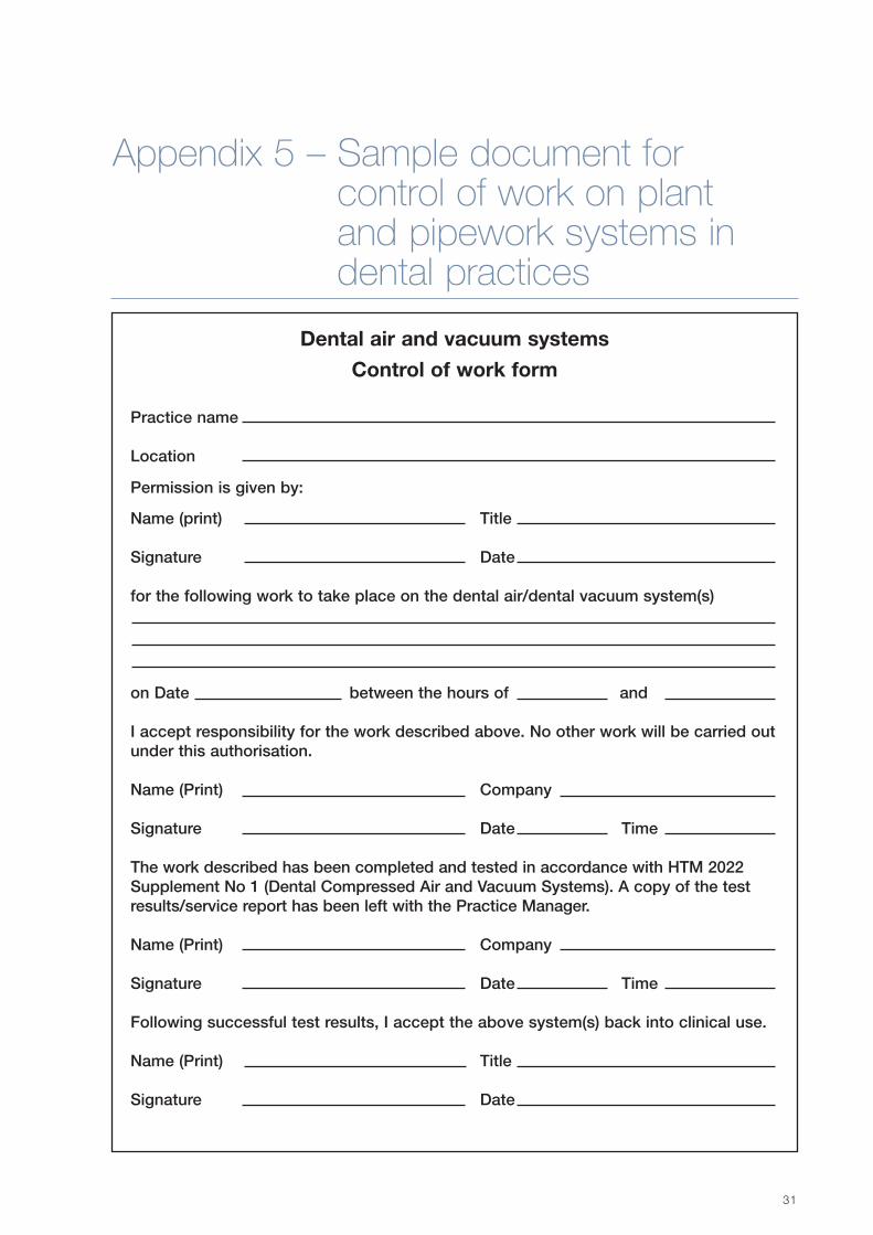
31
Appendix 5 – Sample document forcontrol of work on plantand pipework systems indental practices
Dental air and vacuum systems
Control of work form
Practice name
Location
Permission is given by:
Name (print) Title
Signature Date
for the following work to take place on the dental air/dental vacuum system(s)
on Date between the hours of and
I accept responsibility for the work described above. No other work will be carried outunder this authorisation.
Name (Print) Company
Signature Date Time
The work described has been completed and tested in accordance with HTM 2022Supplement No 1 (Dental Compressed Air and Vacuum Systems). A copy of the testresults/service report has been left with the Practice Manager.
Name (Print) Company
Signature Date Time
Following successful test results, I accept the above system(s) back into clinical use.
Name (Print) Title
Signature Date

DENTAL COMPRESSED AIR AND VACUUM SYSTEMS: HTM 2022 – SUPPLEMENT 1
32
The purpose of this appendix is to offer guidelines tousers/managers of DAVS which are not under theauthority of an AP (MGPS). Where the AP (MGPS) hasresponsibility for the DAVS, the MGPS operational policycan be extended to include the DAVS.
• It is wise to produce a policy that is looseleaf informat. This gives the greatest flexibility whenupdates to personnel details, procedures etc arerequired.
• It is not wise to produce an unnecessarily bulkydocument. The policy should be relevant, clear andconcise.
• Details of personnel telephone numbers andemergency procedures can be inserted asappendices. In this way, updating is made simpler.
• The content of the basic (four-section) structurebelow is not exhaustive but can be used as a startingpoint for policy preparation.
1. Signatories and defined responsibilities
This section will contain the signature(s) of the seniorpartner/partners or principal and will define theaims/objectives and scope of the policy. It will also defineday-to-day responsibility for the DAVS (including thecontrol and recording of work on the systems) andcontain the signature of the person thus defined.
A small (schematic) plan of the installation can be addedto this section.
A reference to responsibility for user training should alsobe included.
2. System components
In this section, the DAVS should be defined in terms oflocation, arrangements for system security, safetyprocedures and routine operation. Nominated personnelshould be referenced to an appendix giving contactdetails. Typical inclusions:
• security key control,
• actions in the event of system failure,
• use of protective equipment,
• safety hazard of equipment,
• start up/shut down procedures,
• user maintenance routines.
3. Operational management
This section should contain details of paperworkcontrolling:
• maintenance;
• installation;
• validation and verification;
• cylinder management procedures (whereappropriate);
• COSHH-related statements, for example procedurefor monitoring of waste anaesthetic gases;
• bacteria-filter changing procedure;
• a reference to fire-safety procedures;
• statements appropriate to the use of maintenancecontractors, for example permission to accessdepartments/equipment.
4. Appendices
a. A list of personnel, contractors etc with contactnumbers and details of arrangements for cover in theevent of absence.
b. A list of actions to be taken in the event of anemergency, for example loss of supply, fire.
Appendix 6 – Operational policy guidelines
33
Activated carbon/charcoal filter: Activated charcoal is often used to remove odours from compressed air systems.An activated charcoal element is often incorporated with the bacteria filter in a medical air system.
Adjustable pressure limiting (APL) valve: A user-adjustable valve that releases gases to the atmosphere or ascavenging system and that is intended to provide control of the pressure in the breathing system. The volume of gasabove that which is needed to achieve the required patient pressure is vented.
After-cooler: A heat-exchanging device used to cool and hence release water by condensation from compressed air.It is usually mounted in the output pipework from a compressor.
Alarm signal status unit: A small indicator panel affixed to all major plant items and displaying normal and faultoperating conditions.
Alarm system: A series of interconnected electronically operated units that continually monitor pipework pressure andplant operating conditions and relay these to appropriate personnel via coloured indicator display panels.
Allowable pressure drop: The maximum permissible pressure drop when a medical gas system is delivering its fulldesign flow.
Amalgam: a mixture of mercury with another metal, dental amalgam consisting of about 50% mercury by weight (othercomponents include silver, zinc, copper, tin).
Anaesthetic agent: A drug used to reduce or abolish feeling.
Anaesthetic gas scavenging system (AGSS): A complete system which conveys expired and/or excess anaestheticgases from the breathing system to the exterior of the building(s) or to a place where they can be discharged safely, forexample to a non-recirculating exhaust ventilation system.
Anaesthetic vaporiser: A device used to facilitate the change of an anaesthetic from a liquid to a vapour.
Analgesic drug: A drug used to reduce or abolish pain.
Area valve service unit (AVSU): A valve assembly within an enclosure provided for maintenance or for connecting atemporary supply or, in emergency, for shutting off the gas flow to a specific area or for the purging and testing of gassupplies after engineering work.
As-fitted drawings: Scale drawings of a pipework system which shows the exact positions of pipework, valves etcwith respect to the layout of the building in which the system is fitted.
Authorised Person (MGPS) – AP (MGPS): A person who has sufficient technical knowledge, training and experiencein order to understand fully the dangers involved and who is appointed in writing by the executive manager on therecommendation of a chartered engineer with specialist knowledge of MGPS. The certificate of appointment shouldstate the class of work that the person is authorised to initiate and the extent of his/her authority to issue and cancelpermits-to-work. The Authorised Person (MGPS) should have read, have understood and be able to apply the guidancein HTM 2022, especially in relation to validation and verification, and should also be completely familiar with the medicalgases pipe routes, their means of isolation and the central plant. He/she should ensure that the work described in anypermit-to-work is carried out to the necessary standards.
Bacteria filter: The final stage of filtration in a medical air system, usually placed before the pipework pressureregulator and often constructed with an integral activated charcoal filter which is used to aid odour removal. For amedical air system, such a filter will be specified to an efficiency of 99.9999% according to the DOP (aerosol) test.
Back-flow: Flow in a direction contrary to the intended normal direction of flow.
Appendix 7 – Glossary of terms

Batch number: A distinctive combination of numbers and/or letters that specifically identify a batch or lot and permitits history to be traced, for example the batch number on a medical gas cylinder.
Bodok seal: A type of (high-pressure) gas seal featuring a (neoprene) rubber flat disc washer bonded to an outer alloyring. Such seals are commonly used in connections of medical gas cylinders to manifold systems.
Breathing system: A gas pathway in direct connection with the patient, through which gas flow occurs at respiratorypressure, and into which a gas mixture of controlled composition may be dispensed. The function of the breathingsystem is to convey oxygen and anaesthetic gases to the patient and remove waste gases from the patient.Scavenging equipment is not considered part of the breathing system. Also referred to as breathing or patient circuit,respiratory circuit or system.
Breathing system (semi-closed): This is a system that allows some of the expired gases to leave the circuit; theremainder mixes with fresh gases and is rebreathed. A carbon dioxide absorber is used in this system.
Breathing tubes: Large bore, flexible tubes of rubber or plastic used in most breathing systems to convey gases toand from the patient. They are usually corrugated to prevent obstruction and increase flexibility.
Buffer vessel: A reservoir used to smooth out variations in pressure caused by varying demands in a PSA system.
Bull nose valve: A type of cylinder valve in which connection of equipment is effected via a threaded valve outlet.
Cannula: A (usually) Hand-held hollow tube designed for insertion into a body cavity. It may be attached to a vacuumsystem for purposes of fluid/detritus removal.
Cannula connector: Cartridge at the end of the hose part of a suction system, intended for fitting of cannulae and forplacement in a mobile support. Also called a suction handpiece.
Carbon dioxide absorber (Circle absorber): A device used to remove carbon dioxide chemically from exhaledpatient gas. Primarily used in closed or semi-closed circle breathing systems, which require carbon dioxide removal tomake rebreathing possible.
Check valves: Also known as unidirectional valves or one-way valves, these units allow passage of a gas or liquid inonly one direction.
Client's representative: The person, or that person's representative, as defined under the designated Standard Formof Building Contract issued by the Joint Contracts Tribunal 1980 (JCT 98).
CCU: Coronary care unit.
Common (fresh) gas outlet: The port through which the mixture of gases and vapours dispensed by an anaestheticmachine is delivered to the breathing system. Also referred to as the machine outlet.
Competent Person (MGPS) – CP (MGPS): A person having sufficient technical knowledge, training and experienceto carry out his/her duties in a competent manner and understand fully the dangers involved, and whose name is onthe register of Competent Persons (MGPS). The register should be maintained by either a specialist contractor or bythe Authorized Person (MGPS) as appropriate.
• He/she should be familiar with and be able to read the record drawings and should have received specific trainingon MGPS.
• He/she should be able to identify all types of medical gases terminal units and should be familiar with all testing andcommissioning procedures referred to in HTM 2022. The person maintaining the register should assess a person'scompetence, taking account of his/her training and experience.
Competent Person (Pressure Systems): As defined by the Pressure Systems and Transportable Gas ContainersRegulations 1989 and subsequently the Pressure System Safety Regulations 2000. A full list of the attributes required isgiven in the Regulations, but in summary, minor systems require a Competent Person (Pressure Systems) of at leastIncorporated Engineer status while intermediate and major systems require Chartered Engineer status.
Compound: A term used to describe a usually locked, fenced area housing a VIE installation. In chemistry acompound is a substance formed by the combination of atoms.
Contamination:
a. Of a water supply: Changes to the nature of the water and, or, deterioration of the quality of the water supplied bythe water supplier, whether it be harmful to health or not.
DENTAL COMPRESSED AIR AND VACUUM SYSTEMS: HTM 2022 – SUPPLEMENT 1
34

b. Of a medical/dental gas supply: Changes in the physical or chemical composition of a medical gas or gas mixturesuch that it no longer meets Pharmacopoeia specifications.
Contract: The agreement concluded between the trust and the contractor, including all specifications, contractor'ssamples, plans, drawings and other documentation which are incorporated or referred to therein.
Contract supervising officer (CSO): The person authorised by the hospital authority to witness tests and checksunder the terms of contract. He/she should have specialist knowledge, training and experience of MGPS and HTM2022.
Contractor: The contractor commissioned typically as a subcontractor for the installation of the MGPS under theStandard Form of Building Contract issued by the Joint Contracts Tribunal 1980 (JCT 98). All contractors working onMGPS and DAVS should be registered to BS EN ISO 9000 with scope of registration defined as appropriate.
Contractor’s Representative (CR): The person nominated by a contractor to oversee the installation of an MGPS.This may be a contractor’s project manager. The CR should have received training appropriate to the work underhis/her control.
Control panel: A term usually applied to the pressure-reducing and monitoring unit used with a VIE. The term is alsoattributed to the gas supply-switching unit of an automatic manifold system and to the electrical control units ofcompressor and vacuum plants.
Control valve: An isolating valve mounted in a medical gas pipework and which is usually used for engineeringpurposes. These valves are usually mounted in ceiling voids, ductwork and plantrooms. They may be locked in theirnormal working position.
Cross-connection:
a. Medical gas: any connections between two or more medical gas services or between a medical gas service and anyother piped service.
b Water system: any connection between water supplied by the water supplier and a source other than from the watersupplier’s mains.
Cryogenics: The science of low temperatures; specifically, those below –40ºC.
Cryogenic liquid system (CLS): A source of supply containing liquefied gas stored under cryogenic conditions. Seealso VIE (vacuum insulated evaporator).
Decanting: The act of transferring a gas (usually oxygen) under pressure, normally from a large cylinder to a smaller,usually transportable, one. This procedure should only be carried out under controlled and documented conditions withthe sanction of the quality controller (QC).
Design flow: A calculated value of gas flow which allows for flow diversity factors and which is used in estimation ofprimary gas source capacity.
Designated medical and nursing officer – DMO/DNO: The medical or nursing officer designated by the chiefexecutive to act as a focal point for communications related to MGPS in a specified department or departments. Therewould ideally be a designated medical officer and a designated nursing officer in each department. The designatedofficer gives permission for any interruption to the MGPS.
Designated Person: A suitably trained person who has been given responsibility for a particular operation involvingmedical gas cylinders, for example responsibility for changing cylinders on the MGPS manifold. A role fulfilled by amedical gas porter.
Diameter Indexed Safety System (DISS): A method of ensuring gas specificity by dimensional coding of connectorsetc.
DOP: Dioctylphthalate. A compound of accurately controllable particle size used in the efficiency testing of filtermedia. This test has generally been replaced by a Dispersed Oil Particulate test (also using the DOP acronym!) which isan aerosol test.
Diversity: When calculating medical gas flows from, say, a ward area an allowance is made for the fact that it would beexceedingly unusual for all terminal units to be in use simultaneously. This allowance is called a diversity factor and, forflow calculation purposes, will give a flow value for a particular area that is less than the mathematical (algebraic) sum ofthe flows from all the terminal units.
APPENDIX 7 – GLOSSARY OF TERMS
35

Dry vacuum system: A pump-driven dental vacuum system in which mouth washings are separated from thepipework airflow (usually) at the dental chair. Only air will flow through the vacuum plant.
Duplex plant: Two identical plant items, for example vacuum pumps. One is the ‘Duty’ or working plant, the other isthe ‘Standby’ plant, which will come on line automatically in the event of failure of the duty plant.
Dynamic pressure: The nominal pressure in a pipework when gas is flowing through it.
Earth bonding (on an MGPS): A low resistance electrical connection between the copper pipework and an electricalearth conductor. Also used to describe electrical continuity connection across flexible (non-conductive) couplings onplant, for example between pump output port and copper exhaust lines on a medical vacuum plant or any electricalconnection to earth of parts of plant, alarm systems etc.
Emergency inlet port: A gas specific connector allowing connection of emergency gas supplies to medical air oroxygen systems in the event of a major gas failure (e.g. primary and secondary supplies).
Entonox: BOC trade name for a 50/50 mixture of nitrous oxide and oxygen. Used for pain relief.
Equanox: Linde trade name for a 50/50 mixture of nitrous oxide and oxygen. Used for pain relief.
Equipment: A device, such as a pressure regulator and flowmeter, which is connected to a single cylinder for theadministration of medical gas to an individual patient or gas apparatus.
Equivalent length: The resistance to flow, in terms of a length of pipe of the same diameter, caused by insertion of afitting; for example, inserting a ball-valve into a 22 mm diameter pipe gives rise to a flow resistance equivalent to 0.6 mof straight pipe: 0.6 m is the equivalent length of the valve.
Emergency supply/reserve manifold – ESM/ERM: A manual or automatic manifold used to supply gas in the eventof failure of the primary supply. A manual ESM is usually specified as support for an automatic manifold and a fullyautomatic ESM for a medical air compressor, oxygen concentrator or cryogenic liquid system, where the latter is asingle vessel primary supply.
Essential supply: An electricity supply intended to be maintained in the event of failure of the main supply. It is usuallyprovided from an on site emergency generator. Medical gas systems and alarms should be connected to the essentialsupply.
Evaporator: A heat-exchanging device in the cryogenic liquid output line from a VIE, in which the liquid boils underconstant pressure at atmospheric temperatures to produce gas.
First fix: The gas-specific back part of a terminal unit. It contains an automatic isolating valve.
Flammable: Capable of burning with a flame. (Analogous to inflammable.)
Floor box: A term frequently applied to the floor mounted distribution unit for compressed air vacuum and electricalservices in a dental surgery. It is usually adjacent to the dental chair.
Flow algorithm: A mathematical equation incorporating diversity factors, allowing the calculation of flow rates of gaseswithin a pipework system.
HTM 22: Hospital Technical Memorandum 22 - 'Piped medical gases, medical compressed air and medical vacuuminstallations' (first published by HMSO for the Department of Health and Social Security as Hospital TechnicalMemorandum 22 in May 1972, and as amended by HN(76)175), and last reprinted in 1978 with minor corrections.
HTM 2022: HTM 2022: 1997, began life as Health Technical Memorandum 22, published in 1974. Currently, thedocument comprises two main volumes:
Volume 1 ‘Design, installation, validation and verification’ ISBN 0-11-322067-7
Volume 2 ‘Operational management’ ISBN 0-11-322068-5.
There are two Supplements to this publication; ‘Dental compressed air and vacuum systems’ ISBN 0-11-322040-5 and‘Medical gas systems for ambulances’ ISBN 0-11-322052-9.
HTM 2022 (1997) is supported by Model Engineering Specification C11 and a Permit to Work System, published by theDepartment of Health and HMSO, respectively.
DENTAL COMPRESSED AIR AND VACUUM SYSTEMS: HTM 2022 – SUPPLEMENT 1
36

The objective of the guidance printed in HTM 2022 is to ensure the provision of medical gas pipework systems thatguarantee the safety of patients served by them.
Hyperbaric chamber: A medical treatment device in which a patient is subjected to (usually) elevated concentrationsof oxygen at a pressure above atmospheric. Blood oxygen levels and oxygen exchange rates are increased.
ICU: Intensive care unit (analogous to ITU).
ITU: Intensive therapy unit.
Inflammable: Capable of burning with a flame. The same as flammable.
Local area alarm: An alarm indicator unit sited in areas of (usually) high dependency and used to signal high or lowmedical gas pipeline pressures to local staff.
Main cylinder storage area: The main area where all cylinders on a site are stored, excluding only those cylinders inuse in manifold rooms or in ready-to-use stores.
Manifold (automatic): A device that allows connection of high-pressure gas cylinders to a medical gas system. Itcomprises a control panel which reduces the pressure to its working value, an automatic changeover facility (empty tofull cylinders) and alarm indicators. Automatic manifolds are designed such that they will continue to supply gas in theevent of an electrical supply failure.
Manifold (manual): A manifold that requires manual intervention to initiate a changeover from empty to full cylinders.
Manifold room: A purpose-built room designed to accommodate a cylinder manifold installation and reserve cylindersas appropriate.
Maximum pressure drop: The maximum allowable pressure difference in a medical gas pipework between plantroom outlet and point of use. For example, the maximum pressure drop allowed in a medical vacuum system at anominal plant room outlet pressure of 450 mmHg is 50 mmHg between the plant room and the back of the mostremote terminal unit, under dynamic conditions. Individual terminal units and flexible hoses will also have maximum allowable pressure drops at flow rates determinedby design parameters and defined in the appropriate design standard(s).
Medical gas: Any gas used in a regime of patient therapy and defined as a medicine under The Medicines Act 1968.
Medical gas pipework systems (MGPS): The fixed medical gases pipework and the associated supply plant orpumping equipment and warning and alarm systems. This definition includes medical compressed air and medicalvacuum installations and anaesthetic gas scavenging systems.
Minimum leak device/low loss tee: A small orifice permanently fitted in a pipework and used as a connection pointfor control devices, for example pressure switches. The device allows removal and repair/refitting of the switch withoutsupply interruption.
Molecular sieve: Any compound capable of selective adsorption of gas molecules, for example the Zeolites used inPSA plant.
Muting: Silencing, on a temporary or permanent basis of the audible alarm on a medical gas alarm system.
NC: Normally closed. Usually used with reference to valves.
NO: Normally open. Usually used with reference to valves.
Nominal distribution pressure: The pressure in a pipework under design flow conditions. For medical gases in theUK the nominal distribution pressure is 400 kPa, except for surgical air, which may have distribution pressures between700 kPa and 1100 kPa. Medical vacuum has a nominal pressure of 450 mmHg (60 kPa) below atmospheric.
Non-flammable: Not capable of burning in air.
Octopus: A device comprising an assembly of suction cups and control mechanisms for restraining the heart duringsurgery. It is operated from the medical vacuum system.
Oxygen-free nitrogen: A gas recommended for use as an inert shield purge during the hot jointing of copper medicalgas pipework. It obviates the need to use flux.
APPENDIX 7 – GLOSSARY OF TERMS
37

Passive system: A reference to a type of AGSS in which there is no active element, that is a pump. Waste gases arepropelled through the system by patient exhalation or the exhaust function of a patient ventilator.
Peak flow: The likely flow through a medical gas system under conditions of maximum demand.
Pendant: A mechanical device, usually ceiling mounted in an operating theatre and designed to facilitate easy accessto medical gas and electrical supplies. It may be a fixed unit (a ‘rigid pendant’), a telescopic pendant (a variation on therigid unit) in which some vertical movement (usually motor driven) of the pendant is possible or a complex unit in whichmovement in all planes is possible. A single, ceiling-mounted hose is also often called a pendant.
Permit-to-work: A form of declaration, or certificate, in eight parts, for signature as appropriate. It states the degree ofhazard involved, defines all services to be worked on and the points where isolation of the affected sections are carriedout, describes the work to be done and requires a signature of a designated medical or nursing officer before work ona MGPS is allowed to commence. It is not a permit for the use of the installation for clinical purposes until all parts havebeen completed. A pro forma is given in the permit-to-work section of HTM 2022 ‘Operational management’.
Pin-Index(ed) Safety System (PISS): A method of ensuring gas-specific connections by the provision of interlockingpin/socket combinations. The pin position is defined for each gas service. Pin-indexing is used on many medical gascylinder valves.
Pin-index valve: A medical gas (cylinder) valve constructed with an integral pin-index system: one or two socketsdrilled into the valve body in positions defined by the gas contained in the cylinder and into which a corresponding itemof pin-indexed equipment, for example cylinder yoke, will fit. Such an assembly offers a gas specific connection.
Pipework carcass: The pipework installation with terminal unit base blocks and area valve service units (excludingpressure switches, flexible assemblies, etc).
Pipework manifold: A pipe to which cylinder tail-pipes are connected, which in turn is connected to the controlequipment by means of which medical gas is delivered to the MGPS.
Pipework odour: Any odour resulting from internal contamination of the MGPS copper pipework, for example byresidual cleaning agent or arising from the supply system. Odours may be detected when testing flexible hoses. Thesearise from plasticisers in the hose material.
PPM: Planned preventive maintenance. A scheme of work contrived to attain maximum plant efficiency.
Premises: The premises should be the hospital site, healthcare building or other establishment where the MGPS isinstalled and the services are to be provided, as defined in the contract.
Pressure gas: A term applied to gases that are delivered at pressures above atmospheric. In the case of medicalgases, pressure gases are oxygen, nitrous oxide, Entonox/Equanox, medical air, surgical air, nitric oxide and oxygencarbon dioxide mixtures. With the exception of surgical air, which is distributed at pressures up to 1100 kPa, medicalgases are distributed at a nominal pressure of 400 kPa.
Pressure-reducing valve: A device used to control the operating pressure in a gas system
Pressure-regulating valve/pressure regulator: Same as pressure-reducing valve.
Pressure safety valve (pressure relief valve): A valve to limit pressure within a pipework or other pressurisedsystem. Medical gas pipework safety valves are usually set at 530 kPa on a 400 kPa system.
Pressure Systems Regulations (1989): (Now replaced by Pressure Systems Safety Regulations (2000) and thePressure Equipment Regulations (1999)). In the regulations three categories of pressure system are defined.
a. Minor systems: pressure less than 20 bar (2.0 MPa) and the pressure volume product for the largest vessel shouldbe less than 2 × 10⁵ bar-litres (20 MPa · m3);
b. Intermediate systems: these include systems that do not fall into either of the other two categories;
c. Major systems: steam-generating systems exceeding 10 MW, pressure storage systems in excess of 106 bar-litres(100 MPa · m3);
Most MGPS and dental air systems fall into the minor systems category. Systems with a largest pressure vessel ×working pressure product of less than 250 bar-litres are exempt from some of the Regulations.
DENTAL COMPRESSED AIR AND VACUUM SYSTEMS: HTM 2022 – SUPPLEMENT 1
38

Pressure swing adsorber (PSA): Medical oxygen concentrator. System comprising compressor(s), nitrogen adsorberunit(s) and reservoir by means of which oxygen-enriched, clean, dry, oil-free air is generated from atmospheric air.
Pressure switch: An adjustable electromechanical device in which varying pressures in a (medical) gas systemactivate electrical contacts and hence an alarm system.
Probe: A gas specific connector used to connect equipment to a terminal unit. It is either attached to a hose (remoteprobe) or to a piece of equipment, for example flowmeter (direct probe).
Procedure: A written method, which has been drawn up by a person familiar with the system and the requirements ofthis HTM, and checked by the QC or Authorized Person (MGPS), as appropriate. It should be signed by both personsand be dated, and include a review date.
Protective cover: A tamper-evident means of protection of the cylinder valve or valve gas-outlet which may beachieved by a viscose seal, plastic cap or metal cover.
Quality controller (QC): A person appointed in writing by the executive manager on the recommendation of the chiefpharmacist. The QC should normally be a pharmacist or other suitably qualified person and should have specialistknowledge, training and experience of MGPS and HTM 2022. The QC is responsible for the quality of the medicalgases; his/her duties include carrying out the quality tests in accordance with the procedures specified in ‘Validationand verification’.
QC (MGPS): Current terminology used to identify a quality controller with MGPS testing duties.
Ready-to-use store: A local subsidiary to the main store for a limited number of medical gas cylinders, usuallycylinders for immediate use and one day’s supply for reserve purposes.
Receiver: A specially strengthened vessel used to store compressed air and smooth out variations in pressure causedby compressor pumps and varying system demand.
Regulator: Same as pressure-reducing valve.
SCBU: Special care baby unit.
Scavenging: The collection of excess gases from a patient breathing circuit and removal of these gases to anappropriate place of discharge outside the working environment.
Scavenging system: An assembly of specific components that collects and removes excess anaesthetic gasesreleased from a breathing circuit. There are three types; Active, in which a pump is used to create a flow which carriesthe waste gases; Passive, in which the patient or patient ventilator provides the driving force for the gas expulsion;Semi-active, in which a small amount of flow in the scavenging system is generated, for example, by the roomventilation system.
Schematic drawing: A drawing of a pipework showing the general layout of the system. Exact positions of thepipework and components with respect to building layout are not shown. Schematic drawings are not usually scaled.
Second fix: The gas specific front part of a medical gas terminal unit. It contains a self-sealing valve.
Semi-dry vacuum system: A dental vacuum system in which a separation similar to that of a dry vacuum systemtakes place but the vacuum pump and separator are combined into one device.
Semi-passive system: A type of AGSS in which there is no integral active pump, but negative pressure is generated,for example, utilising the venturi effect of the ambient-air conditioning system.
Services: The services and goods which the contractor is required to supply in accordance with the contract.
Shield gas: The gas used to provide an inert shield during the brazing of medical gas pipework (usually oxygen-freenitrogen).
Simplex: A single plant item, for example one compressor, used as a primary supply.
Sodium flame test: A method of testing filter element efficiency using a cloud of known size-range sodium chlorideparticles as the challenge medium.
Specialist fire safety advisers: This post is fully described in ‘Firecode: policy and principles’.
Static pressure: The pressure inside a pipework under zero flow conditions.
APPENDIX 7 – GLOSSARY OF TERMS
39

Suction device: A passive entity which can only induce an air flow when connected to a suction machine.
Suction system: Active entity of dental equipment, including a suction machine (vacuum pump) which enables a flowto be induced which is designed to remove spray, liquids and solids from the mouth of a dental patient duringtreatment.
Suitably Qualified Person (SQP): The HTM 22 nomenclature for the Quality Controller (MGPS) – (QC(MGPS)).
Synthetic air: Medical ‘air’ comprising a mixture of approximately 20% oxygen with 80% nitrogen. The air issynthesised (mechanically mixed) from the gases vaporised from cryogenic supplies of liquid oxygen and liquid nitrogen.A synthetic air system is able to provide a hospital site with synthetic air, oxygen and (surgical) nitrogen.
Tail-pipe: A flexible connecting pipe that connects a medical gas cylinder to a medical gas pipework manifold via agas-specific connector.
Telemetry: An electronic processing unit that relays to the gas supplier, via a telephone modem, information on thecontents and internal pressure of a VIE.
Terminal unit: A gas-specific socket, usually wall- or pendant-mounted, which is used as a connection point betweenmedical equipment and the medical gas pipework system.
Test point: A terminal unit and lockable control valve connected to all main plant items and used to facilitateengineering and pharmaceutical testing of the plant.
Third means of supply: A term used to describe additional support for a medical gas (oxygen) system in the event offailure of the primary system and its ESM. A typical example would be provision of a fully automatic manifold system,permanently connected into the hospital end of a main pipework from a cryogenic liquid system installation. Hence,failure of the primary plant or the pipework would not immediately deprive the hospital of oxygen, as the manifold (thethird means of supply) would take over in these circumstances.
Tracheal tube: Also called an endotracheal tube, intratrachael tube and catheter, it is inserted into the trachea andused to convey gases and vapours to the lungs.
Training (gas cylinders): Formal instruction in the safe handling and storage of gas cylinders and associatedequipment to ensure that staff are aware of the dangers involved and will act accordingly.
Trap: A mechanical device that allows automatic drainage of (condensed) water from a pipework or compressed airplant.
Trunking (also called bedhead/walling systems): Wall mounted plastic or metal ductwork, usually with some aestheticappeal, which carries services, such as MGPS, around a patient area.
Trust: Trust means an NHS Trust, Special Health Authority or other health authority as appropriate.
TWA: Time-weighted average (concentration). A way of expressing exposure such that the amount of time spentexposed to each different concentration level is weighted by the amount of time a worker is exposed to that level.
Vacuum insulated evaporator (VIE): A source of supply containing liquefied gas stored under cryogenic conditions.
WAGS: Waste anaesthetic gas system/scavenger/scavenging – same as AGSS.
Wet vacuum system: A pump-driven dental vacuum system in which mouth washings are transferred via a pipeworksystem (and the pump) to a central reservoir for disposal.
White spot nitrogen: Another term for oxygen-free nitrogen. Used as shield gas when brazing medical gas pipework.So called because of the white spot (or spots) painted on the black cylinder shoulder. Note that this cylinder colourcode is changing to meet the new European Standard (EN 1089-3) in which oxygen-free nitrogen is represented by agrey-bodied cylinder with a black shoulder, that is no white spots.
Written Scheme of Examination: A document detailing frequency and degree of examination of a pressure systemby a Competent Person as defined by the Pressure Systems Regulations.
Yoke: A mechanical assembly usually having integral gas-specific components, for example the pins of a pin-indexsystem, for attaching a compressed (medical) gas cylinder to a piece of equipment, for example an anaestheticmachine or a system supply manifold.
DENTAL COMPRESSED AIR AND VACUUM SYSTEMS: HTM 2022 – SUPPLEMENT 1
40

NHS ESTATES PUBLICATIONS
Health Technical Memoranda
HTM 2007 Electrical services: supply and distribution. HMSO, 1993 (issued in 4 parts).
HTM 2022 Medical gas pipeline systems
Vol 1: Design, installation, validation and verification. HMSO, 1997.
Vol 2: Operational management. HMSO, 1997.
Supplements:
Piped medical gases in ambulance vehicles. HMSO, 1997.
Permit-to-work forms. HMSO, 1999.
HTM 2025 Ventilation in healthcare premises. HMSO, 1994 (issued in 4 parts).
Health guidance notes
The Pressure Systems and Transportable Gas Containers Regulations 1989. HMSO, 1993.
Model Engineering Specifications
C11 Medical gases. HMSO, 1996.
Firecode
82. Alarm and detection systems. HMSO, 1996 (new edition in preparation).
Policy and principles. HMSO, 1994.
ACTS AND REGULATIONS
SI 3246: 1994 SI 437: 1999 The Control of Substances Hazardous to Health (COSHH) Regulations. HMSO,1999.
EC Directive 76/464/EEC: Water pollution by discharges of certain dangerous substances. EuropeanCommission.
SI 635: 1989 The Electricity at Work Regulations. HMSO, 1989.
SI 2372: 1992 The Electromagnetic Compatibility Regulations. HMSO, 1992.
The Environment Act 1995. HMSO, 1995.
The Environmental Protection Act 1990. HMSO, 1990.
SI 3242: 1999 The Management of Health and Safety at Work Regulations. HMSO, 1999.
SI 2793: 1992 The Manual Handling Operations Regulations. HMSO, 1992.
The Medicines Act 1968. HMSO, 1968.
41
References

SI 2966: 1992 The Personal Protective Equipment at Work Regulations. HMSO, 1992.
SI 2001: 1999 The Pressure Equipment Regulations. HMSO, 1999.
SI 2169: 1989 The Pressure Systems and Transportable Gas Containers Regulations. HMSO, 1989. Nowreplaced by SI 825: 1996 Pipeline Safety Regulations (1996) and the SI 128: 2000 Pressure Systems SafetyRegulations 2000).
SI 2306: 1998 The Provision and Use of Work Equipment Regulations. HMSO, 1998.
SI 3163: 1995 The Reporting of Injuries, Diseases and Dangerous Occurrences Regulations (RIDDOR).HMSO, 1995.
SI 972: 1996 The Special Waste Regulations. HMSO, 1996.
The Water Byelaws 2000 Scotland.
The Water Industry Act 1991. HMSO, 1991.
SI 3184: 2000 The Water Supply (Water Quality) Regulations. Amended by The Water Supply (Water Quality)(Amendment) Regulations SI 2885: 2001.
The Water Resources Act 1991. HMSO, 1991.
The Water Supply (Water Fittings) Regulations 1999. HMSO, 1999.
SI 1148: 1999 The Water Supply (Water fittings) Regulations. HMSO 1999. Amended by The Water Supply(Water Fittings) (Amendment) Regulations SI 1506: 1999.
SI 3004: 1992 The Workplace (Health, Safety and Welfare) Regulations. HMSO, 1992.
BRITISH AND INTERNATIONAL STANDARDS
BS 1780:1985(1992) Specification for bourdon tube pressure and vacuum gauges. Superseded by BS EN837-1:1998, British Standards Institution, 1992.
BS 6281:Part 2:1982 Devices without moving parts for the prevention of contamination of water bybackflow. Specification for type B air gaps. British Standards Institution, 1982.
BS 6387:1994 Specification for performance requirements for cables required to maintain circuit integrityunder fire conditions. British Standards Institution, 1994.
BS 6759:Part 2:1984 Safety valves. Specification for safety valves for compressed air or inert gases.British Standards Institution, 1984.
BS 6889:1987 Specification for generating racks for synchronous belt drive pulleys. British StandardsInstitution, 1987.
BS 7226:1989 Methods of test for performance of inlet air cleaning equipment for internal combustionengines and compressors. Withdrawn and replaced by BS ISO 5011: 2000, British Standards Institution, 1989.
BS 7671:1992 Requirements for electrical installations. IEE Wiring Regulations. Sixteenth edition. Withdrawnand replaced by BS 7671:2001, British Standards Institution, 1992.
BS EN ISO 9000:2000 Quality management systems. Fundamentals and vocabulary. British StandardsInstitution, 2000.
BS EN 837-1:1998 Pressure gauges. Bourdon tube pressure gauges. Dimensions, metrology, requirementsand testing. British Standards Institution, 1998.
BS EN 1089-3:1997 Transportable gas cylinders. Gas cylinder identification (excluding LPG). Colourcoding. British Standards Institution, 1997.
DENTAL COMPRESSED AIR AND VACUUM SYSTEMS: HTM 2022 – SUPPLEMENT 1
42

BS EN 60529:1992 Specifications for degrees of protection provided by enclosures (IP code). BritishStandards Institution, 1992.
BS EN ISO 10637:2000 Dental equipment. High and medium volume suction systems. British StandardsInstitution, 2000.
BS EN ISO 11143:2000 Dental equipment. Amalgam separators. British Standards Institution, 2000.
BS EN 21942-4:1994 Dental vocabulary – Part 4: Dental equipment. British Standards Institution, 1994.
BS EN ISO 7494:1998 Dental units. British Standards Institution, 1998.
BS EN ISO 9687:1996 Dental equipment – Graphical symbols. British Standards Institution, 1996.
BS ISO 5011:2000 Inlet air cleaning equipment for internal combustion engines and compressors.Performance testing. British Standards Institution, 2000.
MISCELLANEOUS PUBLICATIONS
Advice Sheet A3: Health and safety law for dental practice. British Dental Association (BDA), 1993.
Advice Sheet A12: Infection control in dentistry. British Dental Association (BDA) (under revision for publicationlate 2002), 1996.
Amalgam purchase, use, recovery and release. DETR, 1997.
Anaesthetic agents: controlling exposure under COSHH. Health & Safety Commission’s Health ServicesAdvisory Committee, 1995.
Dental Premises Guide. Water Regulations Advisory Scheme (forthcoming 2002).
Dental amalgam: an environmental code of practice. To be published by DEFRA in 2002.
Occupational exposure limits – EH40/96. Health and Safety Executive, Sudbury, HSE Books, 1996.
Occupational exposure standards for anaesthetic agents – EL(96)33. A ‘Dear Colleague’ letter issued from theNHS Executive Headquarters to NHS Trust Chief Executives and FHSA General Managers on behalf of GeneralDental Practitioners, March, 1996.
Standard Form of Building Contract. Joint Contracts Tribunal (JCT 98).
Testing of piped medical gases. NHS Pharmaceutical Quality Control Committee, 2nd edition, 1991.
Waste management: the duty of care – a code of practice. The Stationery Office.
The Water Regulations Guide. Water Regulations Advisory Scheme, 2001.
Water supply systems – prevention of contamination and waste of drinking water supplies. WaterRegulations Advisory Scheme Technical Support Group (due for release in 2002).
Water Fittings and Materials Directory. Water Regulations Advisory Scheme, 2002.
USEFUL ADDRESSES
The Water Regulations Advisory Scheme (WRAS), Fern Close, Pen-y-Fan Industrial Estate, Oakdale, Gwent, NP14EH. Tel: 01495 248454; Fax: 01495 249234.
REFERENCES
43

DENTAL COMPRESSED AIR AND VACUUM SYSTEMS: HTM 2022 – SUPPLEMENT 1
44
The Agency has a dynamic fund of knowledge which ithas acquired over 40 years of working in the field. Ourunique access to estates and facilities data, policy andinformation is shared in guidance delivered in fourprincipal areas:
Design & Briefing
These documents look at the issues involved inplanning, briefing and designing facilities that reflect thelatest developments and policy around service delivery.They provide current thinking on the best use of space,design and functionality for specific clinical services ornon-clinical activity areas. They may contain schedulesof accommodation. Guidance published under theheadings Health Building Notes (HBNs) and DesignGuides are found in this category.
Examples include:
HBN 54, Facilities for cancer care centresHBN 28, Facilities for cardiac servicesDiagnostic and Treatment Centres: ACAD, CentralMiddlesex Hospital – an evaluationInfection control in the built environment: design andplanning
Operational (Engineering, Facilities Management,Fire, Health & Safety and Environment)
These documents provide guidance on the design,installation and running of specialised building servicesystems and also policy guidance and instruction onFire, Health & Safety and Environment issues. HealthTechnical Memoranda (HTMs) and Health GuidanceNotes (HGNs) are included in this category.
Examples include:
HTM 2007, Electrical services supply and distributionHTM 2010, Sterilization: operational management withtesting and validation protocolsHTM 2040, The control of legionellae in healthcarepremises – a code of practiceHTM 82, Fire safety – alarm and detection systems
Strategic
These are documents which deal with areas of broadstrategic concern and planning issues, including capitaland procurement.
Examples of titles published under this heading are:
EstatecodeHow to Cost a HospitalDeveloping an Estate StrategySustainable Development in the NHS
NHS Estates Policy Initiatives
In response to some of the key tasks of the NHS Planand the Modernisation Agenda, NHS Estates hasimplemented, project-managed and monitored severalprogrammes for reform to improve the overall patientexperience. These publications document the projectoutcomes and share best practice and data with thefield.
Examples include:
National standards of cleanliness for the NHSNHS Menu and Recipe BooksSold on Health
The majority of publications are available in hard copyfrom The Stationery Office Ltd (TSO):
The Stationery OfficePO Box 29Norwich NR3 1GNTelephone: 0870 600 5522Fax: 0870 600 5533http://www.tso-nhse.co.uke-mail [email protected]: 0870 240 3701
Publication lists and selected downloadable publicationscan be found on our website:http://www.nhsestates.gov.uk
For further information please contact our InformationCentre:e-mail: [email protected] tel: 0113 254 7070
About NHS Estates guidance and publications