STATIC FORCE COEFFICIENTS OF THE BASIC FINNER …authors.library.caltech.edu/57813/1/E-73.2.pdf ·...
19
Department of the Navy Bureau of Ordnance Contract NOrd-16200 Task 1 STATIC FORCE COEFFICIENTS OF THE BASIC FINNER MISSILE IN FULLY WETTED FLOW R. W. Kermeen Hydrodynamics laboratory CALIFORNIA INSTITUTE OF TECHNOLOGY Pasadena. California Report No. E-73.2 September 1957
Transcript of STATIC FORCE COEFFICIENTS OF THE BASIC FINNER …authors.library.caltech.edu/57813/1/E-73.2.pdf ·...

Department of the Navy
Bureau of Ordnance Contract NOrd-16200
Task 1
STATIC FORCE COEFFICIENTS OF
THE BASIC FINNER MISSILE
IN FULLY WETTED FLOW
R. W. Kermeen
Hydrodynamics laboratory CALIFORNIA INSTITUTE OF TECHNOLOGY
Pasadena. California
Report No. E-73.2 September 1957

Department of the Navy Bureau of Ordnance
Contract NOrd-16200 Task I
STATIC FORCE
T H E B A S I C
IN FULLY
COEFFICIENTS
FINNER MISSILE
VlETTED FLOW
R. W. Kermeen
OF
Reproduction in whole or in part is permitted for any purpose of the United States Government
Hydrodynamics Laboratory California Institute of Technology
Pasadena, California
Report No. E-73.2 September 1957

ABSTRACT
The results of force tests of models of the Basic Finner missile
configuration in fully wetted flow in the High Speed Tiater Tunnel are
presented. The static lift, pitching moment and drag were measured for
angles of attack up to 14 degrees and for Reynolds numbers from 0.7 to
8.5 x 10⁶. The results of these tests performed on the static force
balance are in good agreement with coefficients determined from free
flight drag studies in the Controlled Atmosphere Launching Tank and at
the U. s. Naval Ordnance Test Station, Pasadena.

INTRODUCTION
The tests described in this report are one phase of an extensive
program in the Hydrodynamics Laboratory to investigate the hydrody11a.mic
coefficients and free flight characteristics of underwater ballistic
missiles. Other phases of this program are the measurement of the dy
namic force and moment coefficients of the Basic Finner missile in the
High Speed Water Tunnel on the angular oscillating and linear oscillating
dynamic balances and free flight studies2 in the Controlled Atmosphere
Launching Tank.
The Basic Finner configuration has been tested in the Bureau of
Standards Hind Tunnel and is being used in experimental and ·i:;heoretical
underwater force coefficients and trajectory investigations at the Experi
mental Towing Tank, Stevens Institute of Technology, the Naval Prov:!.ng
Ground, Dahlgren, Maryland, and the Naval Ordnance Test Station3, Pasadena.
The principal dimensions of the Basic Finner missile configuration
are shown in the sketch, Fig. 1. Models of 1 and 2-inch diameters were used
in these tests. The larger model was fabricated to accommodate the inter
nal force and moment balances necessary when making dynamic tests and in
order to minimize the effects of strut and shield interference. Because of
the extreme length of the 2-inch diameter model, (20 inches), the l-inch
diameter model was tested in order to minimize the wall effects at high
angles of attack.

EXPERIMENTAL SET-UP AND TEST PROCEDURE
The models were mounted on the three component static force balance4
in the 14-in. diameter closed jet test section of the High Speed Water
Tunne15• The models were supported on a single strut, or spindle, at
tached near the midpoint of the body. Two types of support configurations
were used. For most of the tests the model support spindle was shielded
from the flow leaving only a small clearance gap between the model and the
spindle shield. This set-up is shown in the lower photograph of Fig. 2.
In order to calibrate the effect of the shield interference on the forces
a second, image, shield was mounted on the opposite side but not touching
the model (upper photograph, Fig. 2), and the tests repeated. The dif
ference between the runs made 'vith and without image gave the effect of
the addition of the second shield, and, assuming that the shield inter
ference effects were additive, this correction was subtracted from the
first single shield run.
Because of the large chord of the spindle shield compared to the model
diameter for the l-inch model some of the tests were made with the models
mounted on a partially unshielded spindle in order to reduce strut inter
ference at large attack angles. The bare portion of the spindle consisted
of a 1/2-in. diameter circular section tapering in one inch to a straight
cylindrical section 0.290 in. in diameter. The total length of the un
shielded portion of the spindle was 2-in. for the l-in. diameter model and
1-1/2 in. for the two-inch model. With this set-up the· forces and moments
~ere measured on both the model and the unshielded portion of the spindle.
This set-up requires two additional tests in order to calibrate the forces
on the bare spindle and the interference effects. After testing the model
on a single spindle the test was repeated with the model mounted on a simile~
spindle from the opposite tunnel wall, and a second spindle attached to the
force balance with small clearance gap at the model. In this manner the
forces were calibrated for the unshielded portion of the spindle. The inter
ference effects of the spindle were calibrated in a third test by using an
image spindle as was done with the shielded strut.

~1o types of tests were made. The drag coefficient was determined as
a function of Reynolds number at zero attack angle for water velocities
from 4.0 to 65 fps. The maximum speed was limited by the strength of the
model spindle. The lift, drag, and pitching moment \7ere measured by run
ning the tunnel at constant velocity and varying the angle of attack of
the model. l';iost of the tests v1ere made with the model pitched in a plane
normal to one set of fins; however, one series of runs was made with the
afterbody of the model indexed 45 degrees relative to the plane of pitch
angle. The results of these tests are shown separately. Details of the
force balance, read-out system, and data handling methods are described in
Refs. 4 and 6. The force and moment data were reduced to dimensionless coefficients
as follows:
Drag coefficient, CD = DRAG
p/2 v2 A
Lift coefficient, CL LIFT =
p/2 v2 A
Pitching moment coefficient, = MO~!ENT ABOUT MIDPOINT p/2 v2 AD
where:
v
p
A
D
::
= =
=
free stream velocity fps
density of water, slugs
cross sectional area of model, ft2
diameter of model, ft
3
The moments are given about the midpoint of the model, 5.00 diameters from
the nose tip. In addition to the shield and strut interference corrections
the drag coefficient was corrected for horizontal buoyancy. This spurious
drag is due to the static pressure gradient along the test section.

RESULTS AND DISCUSSION
The drag coefficient as a function of Reyno~ds number for the Basic
Finner is shown in ffig. 3. Lift, drag, and pitching moment coefficients
are shown as functions of angle of pitch for several Reynolds numbers in
Fig. 4 for the model pitched normal to the fins and in Fig. 5 for the fins indexed at 45 degrees.
4
Drag data from free flight tests at the Naval Ordnance Test Station,
Pasadena, and in the California Institute of Technology Controlled Atmos
phere Launching Tank, are included in Fig. 3. The drag coefficients re
ported by Stubstad and Waugh3 of NOTS are for Reynolds numbers from 8 x 10⁴
to 9.6 x 10⁵• The drag coefficients are shown in the figure only at the
upper limits of the Reynolds number ranges. Price2 reports a drag coeffi- .
cient of 0.493 at a Reynolds number of approximately 3.6 x 10⁵ in the free flight test at CIT. The agreement between the water tunnel drag coeffi
cients and those of NOTS i.s excellent. Though the CIT free flight tests
were made at smaller Reynolds numbers than the tunnel tests these results
are also in close agreement.
The drag coefficient showed a sharp peak at a Reynolds number of
2.7 x 10⁶ for all tests of the 2-inch diameter model. In addition the drag
coefficient increases with increasing Reynolds numbers over the entire range.
This trend is also apparent in the curves of drag coefficient vs attack
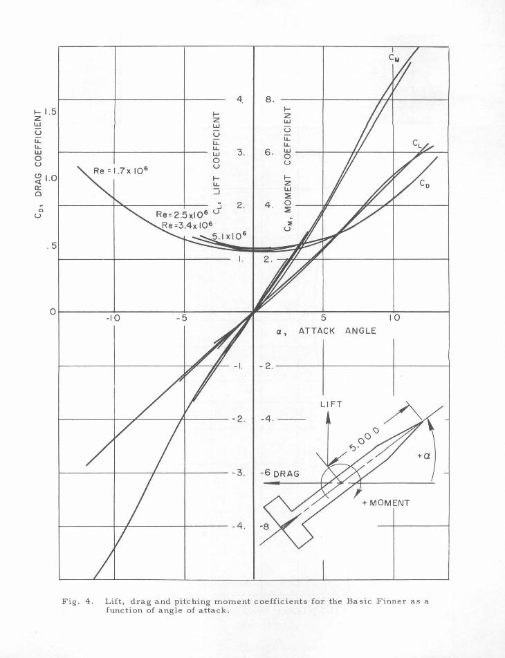
angle, .:o"':tg. 4. Lift, drag, and pitching moment coefficients are shown for Reynolds
6 numbers of 1.7, 2.5, 3.4, and 5.1 x 10 for angles of attack up to 14 de-
grees in Fig. 4. The lift and moment show almost no variation with
Reynolds number over this range. I''or the test results shown in Fig. 4, the
model was pitched in a plane normal to one set of fins. In the tests of
lig. 5, the model afterbody· was rotated 45 degrees and the model pitchad
in a plane 45 degrees to all four fins. nith the model pitched 45 degrees
to the plane of the fins, the lift, drag and moment coefficients, as ex
pected, are less than with the model pitched normal to one set of fins for
angles of attack greater than 5 degrees.

REFERENCES
1 Kiceniuk, Taras, 11An Experimental Determination of Dynamic Coeffi-cients For the Basic Finner Missile by Means of the Angular Dynamic Balance 11 , California Institute of Technology, Hydrodynamics Laboratory Report No. E-?3.3, June 195?
2 Price, D. A. Jr., 11.r"'ree Body Modeling of the Dynamics of a Fin-Stabilized Ballistics Missile in Honspinning Vertical Trajectories", California Institute of Technology, Hydrodynamics Laboratory Report No. E - ?3.1, April 195?.
3 Stubstad, G. W ., .and Tiaugh, J. G., "Drag Coefficient of Fully W'"etted Basic Finner l'.iissile", u. S. Naval Ordnance Test Station, NAVord Report 5269, June 1956.
4 Hotz, G. M., and McGra'l7, J. T., 11The High Speed l7ater Tunnel Threea omponent Force Balance", California Institute of Technology, Hydrodynamics Laboratory Report No. 4?-2, January 1955.
5
5 Knapp, R. T ., Levy, J ., O'Neill, J. P ., Brorm, F. B., 11The Hydrodynamics Laboratory of the CaJifornia Institute of Technology 11 , Trans. ASME, Vol. ?0, No. 5, pp 43? - 45?, July 1948
6 Kermeen, R. n., "Water Tunnel Tests of NACA 4412 and Walchner Profile ? Hydrofoils in Noncavi tating and Cavitating Flows 11 , California Institute of Technology, Hydrodynamics Laboratory Report No. 4?-5, ? ebruary 1956.

F'IGURE TITLES
Fig. 1 Sketch of the Basic Finner missile configuration.
Fig. 2 One inch diameter Basic Finner model mounted in the High Speed Dater Tunnel. Upper photograph - single shield; lower photograph, image set-up.
Fig. 3 Drag coefficient as a function of Reynolds number for the Basic Finner in fully wetted fiow.
Fig. 4 Lift, drag and pitching moment coefficients for the Basic Finner as a function of angle of attack.
Fig. 5 Lift, drag and pitching moment coefficients for the Basic Finner as a function of attack angle. Model pitched at 45 degrees to plane of fins.
6

MOM
ENT
REFE
REN
CE
CENT
ER
~
J 0
0
-------------------.. ~~~~ 0
0
--.
0 g
• 0
. 0
..:
r<l
"""
-1 ~ I
5.0
00
D
_,
I' '-
-S
UP
PO
RT
SP
IND
LE
r---------~.9eo
.!
1 j
1-1
.00
0 0
r---------------------1
0.0
00
0 _
__
__
__
__
__
__
__
__
__
___j
I
Fig
. 1
. S
ketc
h o
f th
e B
asi
c F
inn
er
mis
sil
e c
on
fig
ura
tio
n.

Fig. 2. One-inch diameter Basic Finner model mounted in the High Speed Water Tunnel. Lower photo - single shield. Upper photo - image setup.

1.0 .8 ' '
.6 '
t z w.5
I u lJ
.. ~.4
0 u
~
(.!)
c:
r.3
Q:
0
p 0 u '
.2 I .I
~
"''
L
:---
----,...
..-~I
-C
AL
T z
C
IT
~ N
OT
S3
I
i
----
-1
-.2
.3
.4
.5
.6
.8
1.
0 2
.0
3.0
4.0
5.
0 6.
0 8
.0
RE
YN
OL
DS
N
UM
BE
R
x 1
0 6
Fig
. 3
. D
rag
co
eff
icie
nt
as a
fu
ncti
on
of
Rey
no
lds
nu
mb
er
for
the B
asi
c F
inn
er
in f
ull
y w
ett
ed
flo
w.
4. 8. ..... 1.5 ..... ..... z z z w w w u u u u.. iL u.. u.. u.. u.. UJ w 3. 6. w 0 0
0 u u u
~ 1.0 ..... ..... u.. z a:: :::::; w
0 ~ ~ .:. 2. 4 . 0
0 Re= 2.5xl0 6 u ~
u ~
Re=3.4x 10⁶ ::E
5.1 xl0 6 u
.5
I . 2.
Ol--------~----------+---------~~---------5~--------_.o------~ -I 0 -5 I
a, ATTACK ANGLE
Ll FT
+MOMENT
Fig. 4 . Lift, drag and pitching moment coefficients for the Basic Finner as a function of angle of attack.

o~---------~o-----------~5~--------~----------~5-----------~~o------~
a, ATTACK ANGLE
-I. - 2. ----t------t--------1
-2. -4 . ----1------+----~
BASIC FINNER
-3. -6.
~------~----------+-~----- -4 . -8 .
FIN POSITION- 45°
Fig. 5. Lift, drag and pitching moment coefficients for the Basic Finner as a function of attack angle. Mode l pitched at 45 degrees to plane of fins.


Copy No.
1-4
5-8
9-10
11-13
14-18
19-21
22
23-24
25-26
27-28
29-30
31
32
33
34
35-36
DISTRIBUTION LIST
Chief, Bureau of Ordnance, Navy Dept., Washington 25, D. C. Attn: Code Re0-3
Chief, Bureau of Ordnance, Navy Dept., Washington 25, D. C. Attn: Code Re U
Chief, Bureau of Ordnance, Navy Dept., Washington 25, D. C. Attn: Code Ad3
Chief, Bureau of Aeronautics, Navy Dept., Washington 25, D. C.
Chief, Bureau of Ships, Navy Dept., Washington 25, D. C.
Chief, Office of Naval Research, Navy Dept., Washington 25, D. C. Attn: Code 438
Commanding Officer, Cffice of Naval Research Branch Office, 1030 East Green Street, Pasadena 1, California
Commanding Officer and Director, David Taylor Model Basin, Washington 7, D. C.
Commanding Officer, U. S. Naval Underwater Ordnance Station, Newport, Rhode Island
Commander, U. S. Naval Ordnance Laboratory, White Oak, Silver Spring, Maryland
Commander, U. S. Naval Ordnance Test Station, Pasadena, California
Commander, U. S. Naval Ordnance Test Station, China Lake, California
Director, Experimental Towing Tank, Stevens Institute of Technology, via: Bureau of Aeronautics Representative c/o Bendix Aviation Corp. , Eclipse -Pioneer Division, Teterboro, New Jersey
Director, Ordnance Research Laboratory, Pennsylvania State University, University Park, Pennsylvania
Alden Hydraulic Laboratory, Worcester Polytechnic Institute, Worcester, .Mass., via: Inspector of Naval Material, 495 Summer Street, Boston 10, Mass.
Librarian, U. S. Naval Postgraduate School, Monterey, Calif.


Copy No.
37-46
47-49
50-51
52.
53
54
55-56
57
58-63
DISTRIBUTION LIST (cont'd)
British Joint Services Mission, Navy Staff, via: Chief, Bureau of Ordnance, Navy Dept., Washington 2.5, D. C., Attn: Code AdS
Commander, U. S. Naval Proving Ground, Dahlgren, Virginia
National Advisory Committee for Aeronautics, Langley Memorial Aeronautical Laboratory, Langley Field, Virginia
National Advisory Committee for Aeronautics, Lewis Flight Propulsion Lab., Cleveland Airport, Cleveland, Ohio
Director, National Advisory Committee for Aeronautics, 1512. H Street, N. W., Washington 2.5, D. C.
Director, National Advisory Committee for Aeronautics, Ames Laboratory, Moffett Field, California
Commander, Air Research and Development Command, Post Office Box 1395, Baltimore 3, Maryland
ASTIA Reference Center, Technical Information Division, Library of Congress, Washington 2.5, D. C.
Director, Armed Services Technical Information Agency, Documents Service Center, Knott Building, Dayton Z, Ohio. Attn: DSC -SA