State of the Art of Compact Separators for Production ... · 2/22/2018 · Control and Measurement...
77
21 – 22 February 2018 Houston, TX Copyright 2018, Letton Hall Group. This paper was developed for the UPM Forum, 21 – 22 February 2018, Houston, Texas, U.S.A., and is subject to correction by the author(s). The contents of the paper may not necessarily reflect the views of the UPM Forum sponsors or administrator. Reproduction, distribution, or storage of any part of this paper for commercial purposes without the written consent of the Letton Hall Group is prohibited. Non-commercial reproduction or distribution may be permitted, provided conspicuous acknowledgment of the UPM Forum and the author(s) is made. For more i nformation, see www.upmforum.com. State of the Art of Compact Separators for Production Measurement – from Lab to the Field Drs. Ram S. Mohan and Ovadia Shoham
Transcript of State of the Art of Compact Separators for Production ... · 2/22/2018 · Control and Measurement...

21 – 22 February 2018 Houston, TX
Copyright 2018, Letton Hall Group. This paper was developed for the UPM Forum, 21 – 22 February 2018, Houston, Texas, U.S.A., and is subject to correction by the author(s). The contents of the paper may not necessarily reflect the views of the UPM Forum sponsors or administrator. Reproduction,distribution, or s torage of any part of this paper for commercial purposes without the written consent of the Letton Hall Group is prohibited. Non-commercial reproduction or distribution may be permitted, provided conspicuous acknowledgment of the UPM Forum and the author(s) is made. For moreinformation, see www.upmforum.com.
State of the Art of Compact Separators for Production
Measurement – from Lab to the Field
Drs. Ram S. Mohan and Ovadia Shoham

1-2
TUPREP
TUDRP
TUFFP
TUSTP
TUALP
TUPDP
E/CRC
TUSTP
EROSION /CORROSION RESEARCH CENTER
PARAFFIN DEPOSITIONDELAYED COKING (TUDCP)
DRILLING RESEARCH
TU-FLUID FLOW
ARTIFICIAL LIFT
PETROLEUM RESERVOIR EXPLOITATION
TU-SEPARATION
TECHNOLOGY
PROJECTS
TUSMP SAND MANAGEMENT
TUCTMRCOIL TUBING MECHANICS
RESEARCH
TU Major Research Consortia
1-3
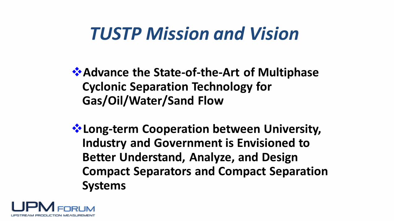
Advance the State-of-the-Art of Multiphase Cyclonic Separation Technology for Gas/Oil/Water/Sand Flow
Long-term Cooperation between University, Industry and Government is Envisioned to Better Understand, Analyze, and Design Compact Separators and Compact Separation Systems
TUSTP Mission and Vision
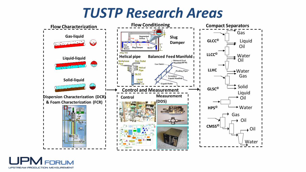
Control and Measurement
Control Measurement (DDS)
Flow Conditioning
Slug Damper
Helical pipe Balanced Feed Manifold
Oil
Oil
Water
Gas
GLCC©
Gas
Liquid
Compact Separators
Water
Oil
LLHC
Oil
Water
LLCC©
CMSS©
Gas
Solid Liquid
Water
Oil
HPS©
GLSC©
Flow Characterization
Dispersion Characterization (DCR)& Foam Characterization (FCR)
Gas-liquid
Liquid-liquid
Solid-liquid
TUSTP Research Areas
Add-in Libraryvx1.4
1-5
GLCC©vx8.5
FLOPATNvx2.1
Slug Damper vx2.1
TUSTPTUSTP
GAS-LIQUID
CYLINDRICAL CYCLONE
LIQUID-LIQUID
CYLINDRICAL CYCLONE
GAS-LIQUID FLOW
PATTERN PREDICTION
GAS-LIQUID
FLOW CONDITIONING
LLCC©vx1.1
Hydrocyclone-vx4.0DEOILING &DESANDING
HYDROCYCLONE
OIL-WATER
FLOW PATTERNFlowpatOW-vx1.2
Pressure Gradient
OIL-WATERDPDLOWDisp-vx1.0
1-5
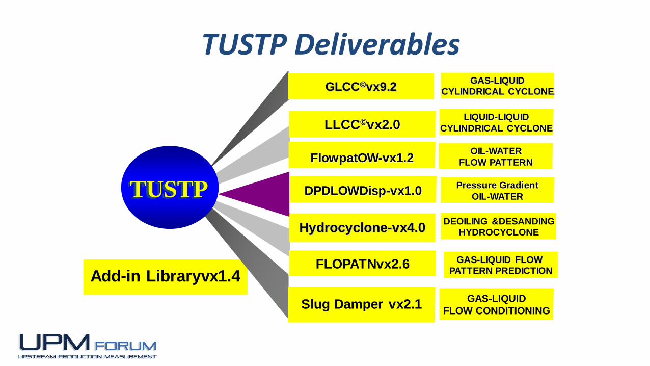
GLCC©vx9.2
FLOPATNvx2.6
Slug Damper vx2.1
TUSTPTUSTP
GAS-LIQUID
CYLINDRICAL CYCLONE
LIQUID-LIQUID
CYLINDRICAL CYCLONE
GAS-LIQUID FLOW
PATTERN PREDICTION
GAS-LIQUID
FLOW CONDITIONING
LLCC©vx2.0
Hydrocyclone-vx4.0DEOILING &DESANDING
HYDROCYCLONE
OIL-WATER
FLOW PATTERNFlowpatOW-vx1.2
Pressure Gradient
OIL-WATERDPDLOWDisp-vx1.0
TUSTP Deliverables
1-6
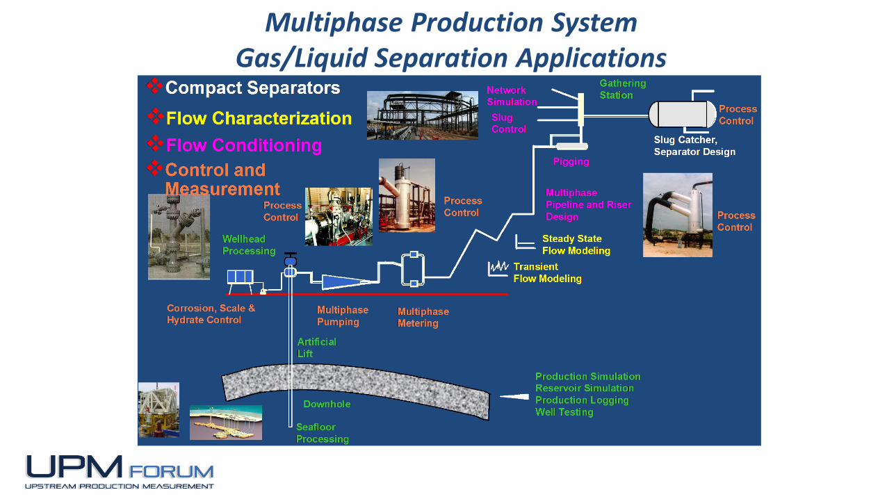
Multiphase Production SystemGas/Liquid Separation Applications
7
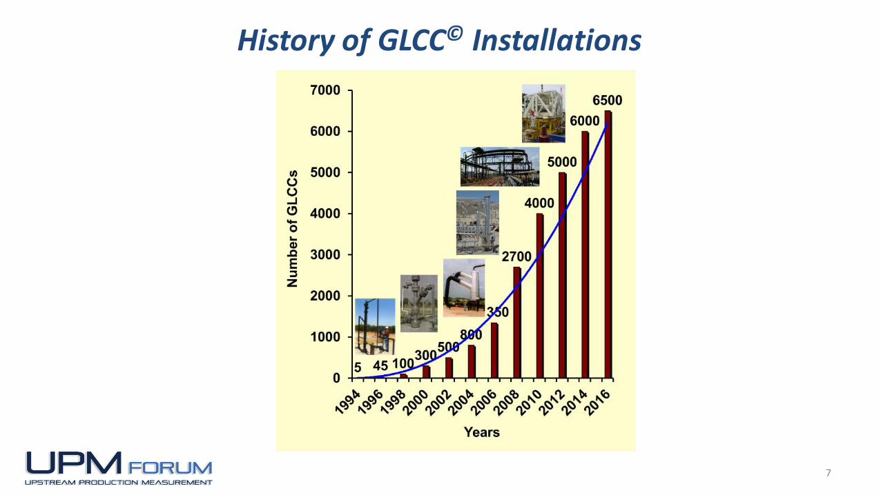
History of GLCC© Installations

1-8
Separator Size Comparison
Metering Loop with Single-Phase Meters
Metering Loop with Multiphase Meters (Gas Knockout)
GLCC as a Pre-separator for De-bottlenecking
GLCC as a Bulk Separator
High Pressure GLCC for Wet Gas Application
Portable GLCC
Offshore Application
Mining Application
GLCC for Severe Slugging Applications
Low API Gravity Application (12 0API)
Other Applications
GLCC after First Stage Compressor
GLCC for Raw Gas Lift
GLCC as a Gas Scrubber
GLCC in a Multiphase Pumping Loop
GLCC© Field Applications(over 6500 as of 12/2016)

1-9
Horizontal
Separator
(19ft x 75ft)
Vertical
Separator
(9ft x 35ft)
GLCC©
Compact Separator
(5ft x 20ft)
Separator Size Comparison
Ref: Gomez, L.E, Mohan, R.S., Shoham, O. and Kouba, G.E.: “EnhancedMechanistic Model and Field Application Design of Gas-Liquid Cylindrical CycloneSeparator,” SPE 62487, SPE Journal, vol. 5 (2), 190-198, June 2000.

1-10
Originally Developed by Chevron in La-Habra, CA (Dr. Gene Kouba, early ‘90s)
GLCC©/Net Oil Computer Configuration (early ‘90s)
Device Patented in 1994
JIP/Research Consortium formed, TU Separation Technology Projects (TUSTP) (1994)
GLCC© Historical Development

1-11
More than Forty units in one Oklahoma field
Up to 1200 bpd and 80 GOR with one basic design
38 deg API crude with water cuts up to 95%
Beam pumping units with pulsating flow
0.5 ft X 9 ft
50 psia, 80 F
Field Application Design
Chevron Single Well Test Loop
1-12
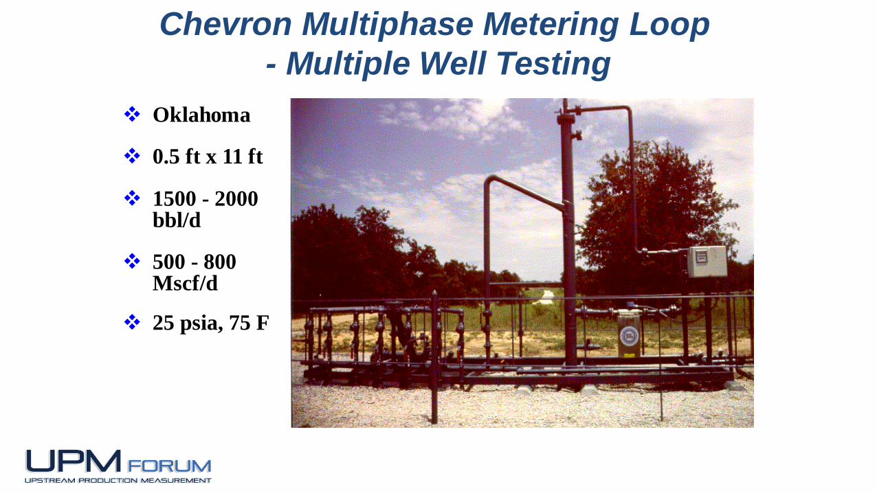
Oklahoma
0.5 ft x 11 ft
1500 - 2000 bbl/d
500 - 800 Mscf/d
25 psia, 75 F
Chevron Multiphase Metering Loop
- Multiple Well Testing

1-13
GLCC©s in West Texas (Single Well Testing)
Gross liquid rates from 5 to 2000 bpd Gas rates to 50 Mscfd Field allocation factor better than 0.97

1-141-14
GLCCS IN WEST TEXAS (MICROMOTION INC.)
High gas rates from primary lift wells and ESPs
Gas rates up to 2 MMscfd
2-inch ELITE meter on gas flow
Density measurement for CO2 fraction
Field Application Design
1-15
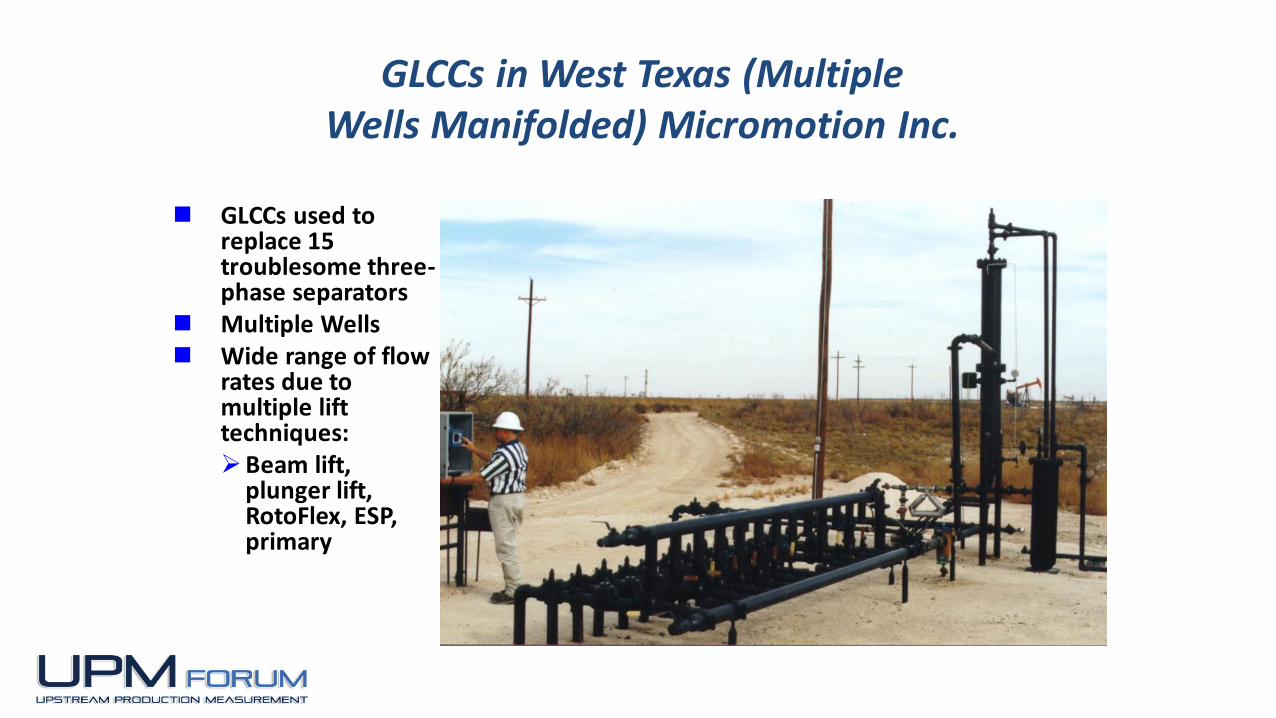
GLCCs in West Texas (Multiple Wells Manifolded) Micromotion Inc.
GLCCs used to replace 15 troublesome three-phase separators
Multiple Wells Wide range of flow
rates due to multiple lift techniques:Beam lift,
plunger lift, RotoFlex, ESP, primary

1-16
JIP – Chevron, BP, Krebs
(1995)
Field Test at BP's Wytch
Farm
6” GLCC for control of
GLR input to desander
Combination worked well
Optimal solid/liquid
separation
2-5% GCU
GLCC© as Part of a Wellhead DesanderBP’s Wytch Farm (UK)

1-17
3 ft ID, 11 ft tall
76 psia, 360 F
6,000 bbl/d,
10.0 MMscf/d
Integrated liquid
level control
Automated Well Test Unit – Minas Indonesia

1-18
5 ft ID, 20ft tall
185 psia, 360 F
200,000 bbl/d,
71 MMscft/d
Integrated liquid
level control with
Dead band filter
o
Bulk Separation Application – Minas Indonesia

1-19
Spot 1 = 198.0 F
Spot 2 = 204.0 F
Spot 3 = 190.3 F
Spot 4 = 183.5 F
Spot 5 = 182.0 F
Spot 6 = 206.0 F
*>209,1°F
*<115,7°F
120,0
130,0
140,0
150,0
160,0
170,0
180,0
190,0
200,0
Spot 1 = 197.8 F
Spot 2 = 203.3 F
Spot 3 = 195.9 F
Spot 4 = 176.0 F
Spot 5 = 205.0 F
*>214,3°F
*<-4,0°F
0,0
20,0
40,0
60,0
80,0
100,0
120,0
140,0
160,0
180,0
200,0
Confirmed operation of dual inlet
during extremely high liquid rates
Slugging Mitigation:Field Test for Model Validation
1-20
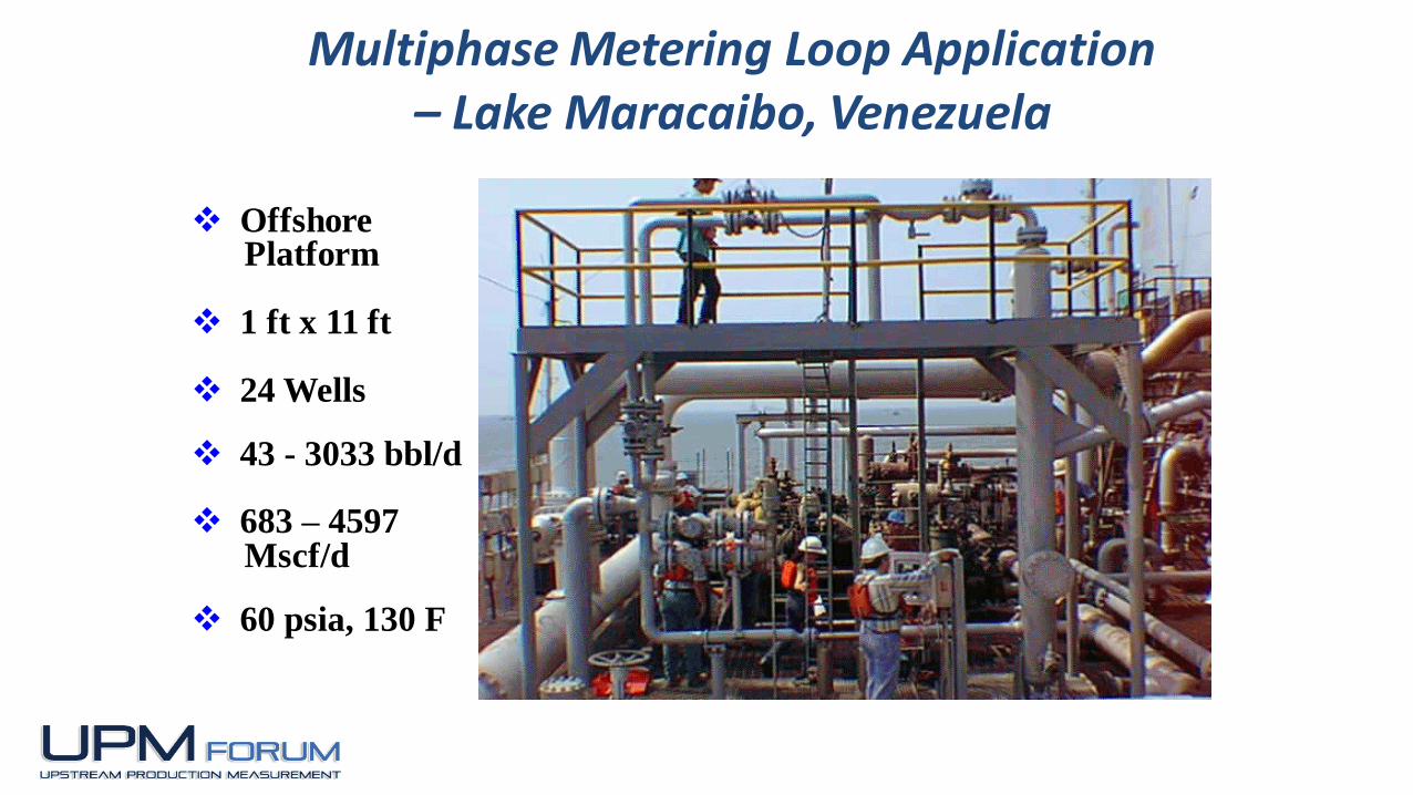
OffshorePlatform
1 ft x 11 ft
24 Wells
43 - 3033 bbl/d
683 – 4597Mscf/d
60 psia, 130 F
Multiphase Metering Loop Application – Lake Maracaibo, Venezuela

1-21
Courtesy SMS, Inc.
12 API Oil - Bakersfield, CA
12’’ Column
3” Inlet
2” CMF- Liquid
Very Low GOR
Level Control
Temperature:
120 to 250 F.

1-22
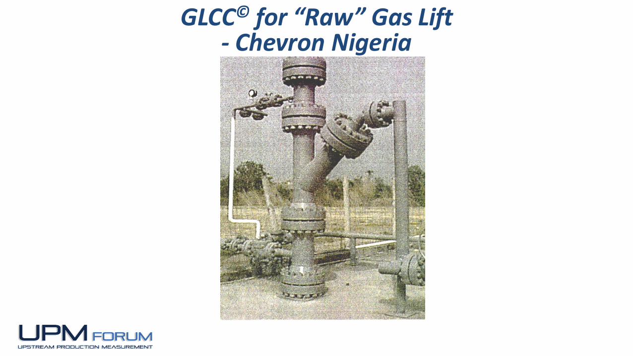
GLCC© in Chevron Nigeria “Raw” Gas Lift
1998 SPE Production Separation Workshop
HIGH PRESSURE
SOURCE WELL
LOW PRESSURE
GAS LIFT WELL
TO LIQUID
FLOWLINE
HIGH PRESSURE
LIFT GAS
1-23
GLCC© for “Raw” Gas Lift - Chevron Nigeria

1-24
China Offshore Platform GLCC© for Wet Gas Metering (CNOOC)
Courtesy Veritas-MSI
(China)
(Natural Gas and Condensate)

1-25
China Offshore Platform GLCC© for Wet Gas Metering (CNOOC)
(Natural Gas and Condensate)

1-26
GLCC© for Well Test Metering Skid (Shengli Oil Field - CNPC)
Courtesy Veritas-MSI
(China)
(High Liquid and Low Gas Rates)

1-27
GLCC© for Well Test Metering Skid (Sinopec)
Courtesy Veritas-MSI
(China)
1-28
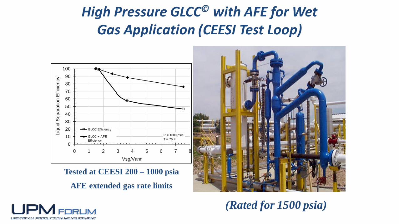
High Pressure GLCC© with AFE for Wet Gas Application (CEESI Test Loop)
(Rated for 1500 psia)
0
10
20
30
40
50
60
70
80
90
100
0 1 2 3 4 5 6 7 8
Vsg/Vann
Liq
uid
Se
pa
ratio
n E
ffic
ien
cy
GLCC Efficiency
GLCC + AFE
Efficiency
P = 1000 psia
T = 76 F
Tested at CEESI 200 – 1000 psia
AFE extended gas rate limits

1-29
CPI - DURI AREA-10 GLCC©sWITH SLUG DAMPER (Indonesia)
Courtesy
Chevron

1-30
(Courtesy SMS, Inc.)
GLCC with Slug Damper
Field Application Design
1-31
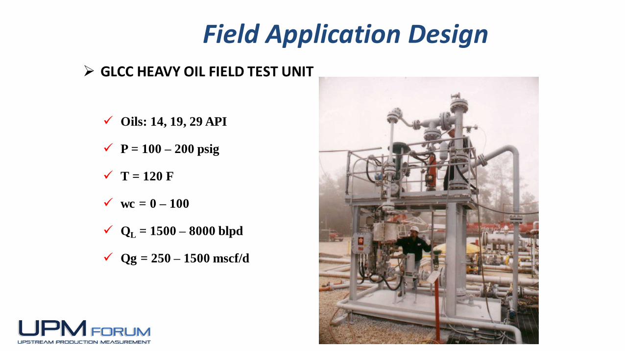
GLCC HEAVY OIL FIELD TEST UNIT
Oils: 14, 19, 29 API
P = 100 – 200 psig
T = 120 F
wc = 0 – 100
QL = 1500 – 8000 blpd
Qg = 250 – 1500 mscf/d
Field Application Design
1-32
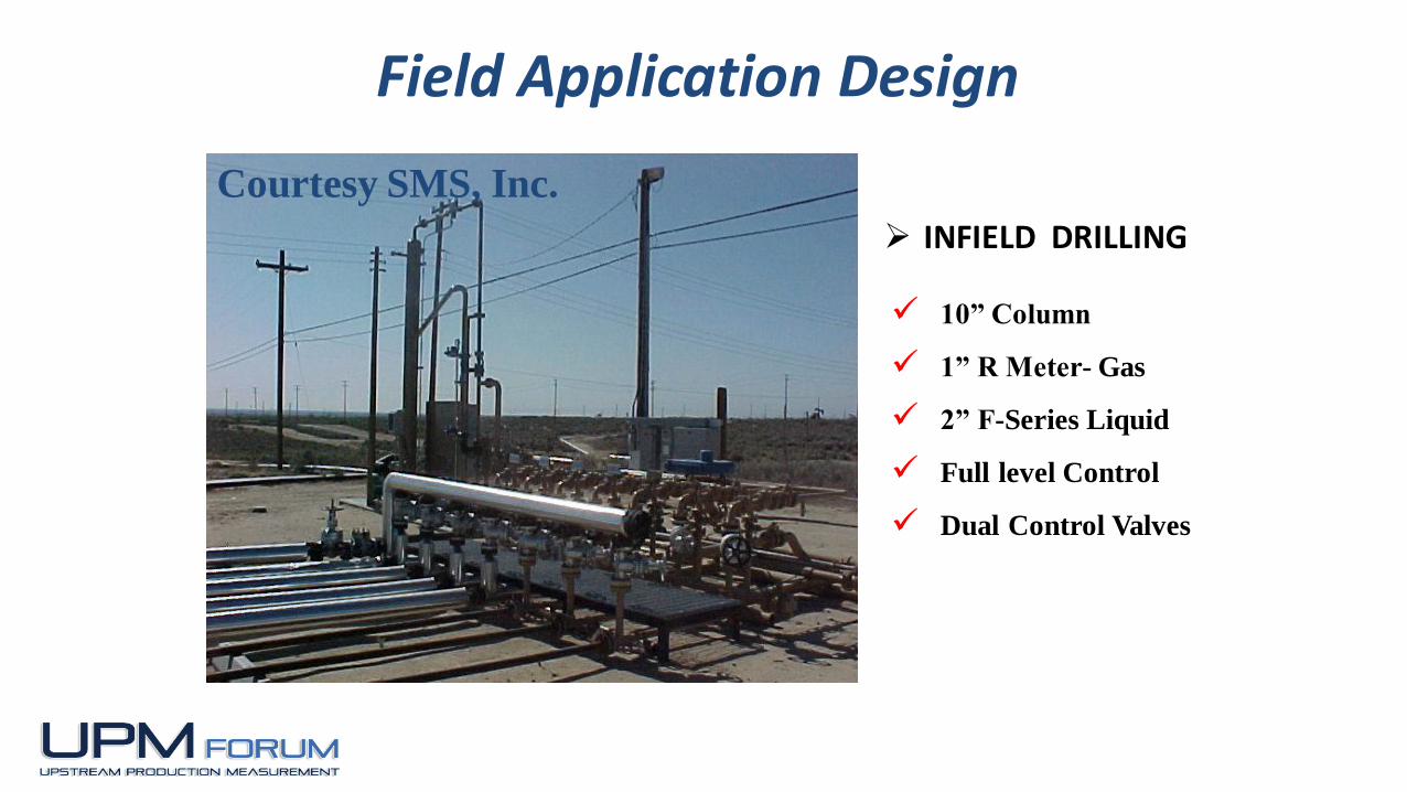
Courtesy SMS, Inc.
INFIELD DRILLING
10” Column
1” R Meter- Gas
2” F-Series Liquid
Full level Control
Dual Control Valves
Field Application Design

1-33
Courtesy SMS, Inc.
GAS WELL WITH CONDENSATE
10” Column
3MMSCFD GAS – 20 BPD Gross
2” F-Series Gas
1” F-Series Liquid
Capacity 12MM
Field Application Design
1-34
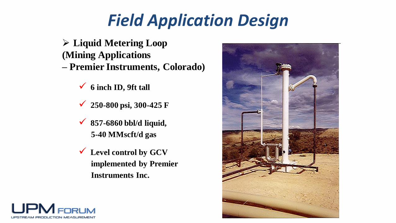
Liquid Metering Loop
(Mining Applications
– Premier Instruments, Colorado)
6 inch ID, 9ft tall
250-800 psi, 300-425 F
857-6860 bbl/d liquid,
5-40 MMscft/d gas
Level control by GCV
implemented by Premier
Instruments Inc.
Field Application Design

1-35
GLCC Metering Skids for Exxon, Chad (Premier Instruments)
Field Application Design

1-36
GLCC IWT LOOP FOR POZA RICA, MEXICO (Wet Gas Application)
GLCC installed by
Emerson Process
Management - IWT
Field Application Design
1-37
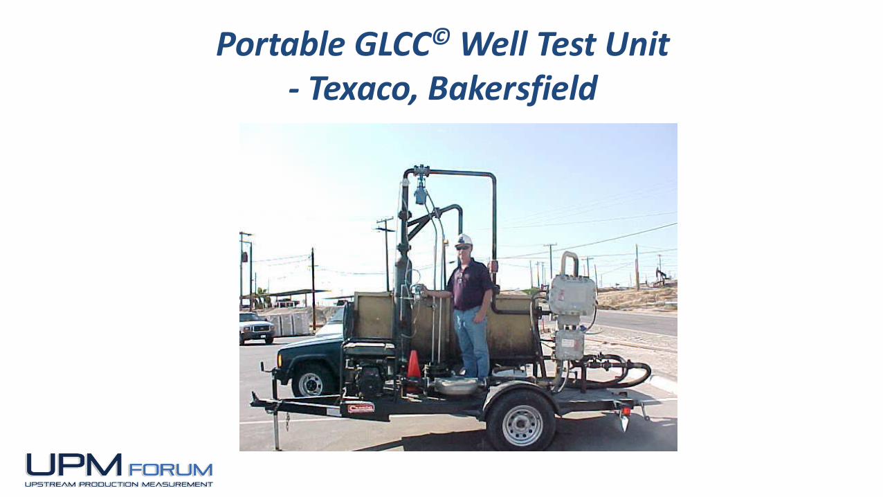
Portable GLCC© Well Test Unit- Texaco, Bakersfield

1-38
Portable GLCC© –Gas ProductionCourtesy SMS, Inc.
1-39
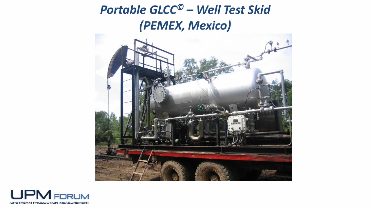
Portable GLCC© – Well Test Skid (PEMEX, Mexico)
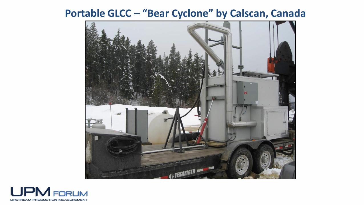
Portable GLCC – “Bear Cyclone” by Calscan, Canada

“Bear Cyclone” by Calscan, Canada
Calscanhas developed The
Bear Cyclone Separator
Package
• Innovated high efficiency
Cyclone Separator
• Easy to install
• Modern non venting
control system – Zero
Green House Gas Emission
• Small foot print
• All Electric Control
System
• Low power flow computer
for gas & liquid
measurement
1-42
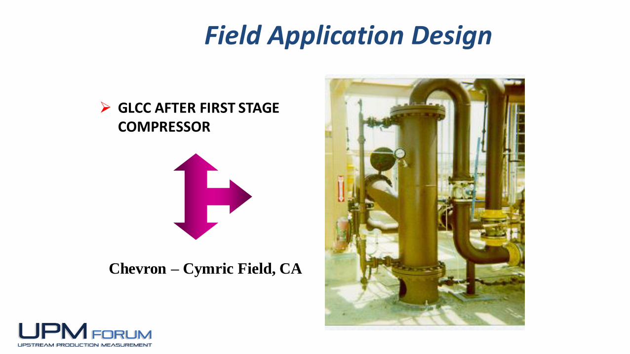
GLCC AFTER FIRST STAGE COMPRESSOR
Chevron – Cymric Field, CA
Field Application Design
1-43
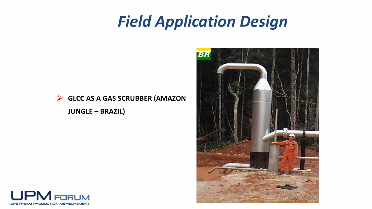
GLCC AS A GAS SCRUBBER (AMAZON
JUNGLE – BRAZIL)
Field Application Design
1-44
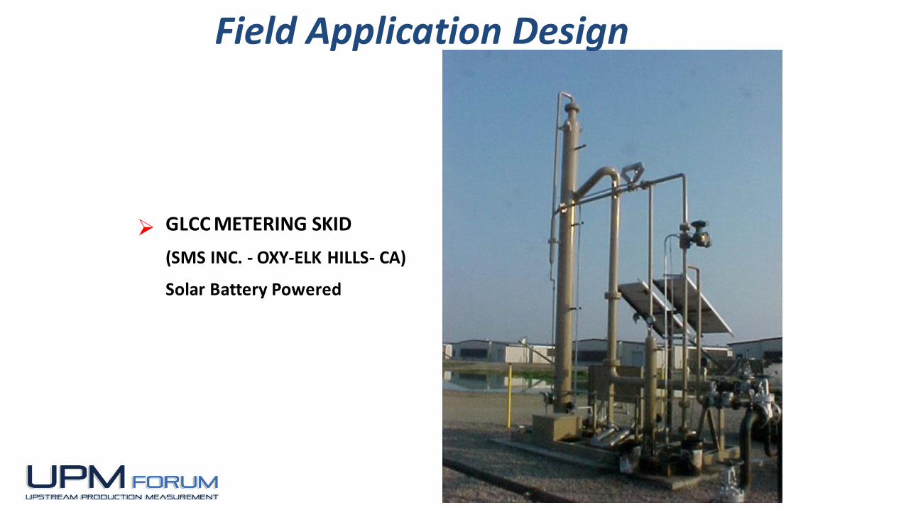
GLCC METERING SKID
(SMS INC. - OXY-ELK HILLS- CA)
Solar Battery Powered
Field Application Design

1-45
Courtesy
SMS, Inc.
10” Column
Multi Liquid Flow Ranges
Multi Gas Flow Ranges
10” GLCC 48 WELL HEADER
Field Application Design
1-46
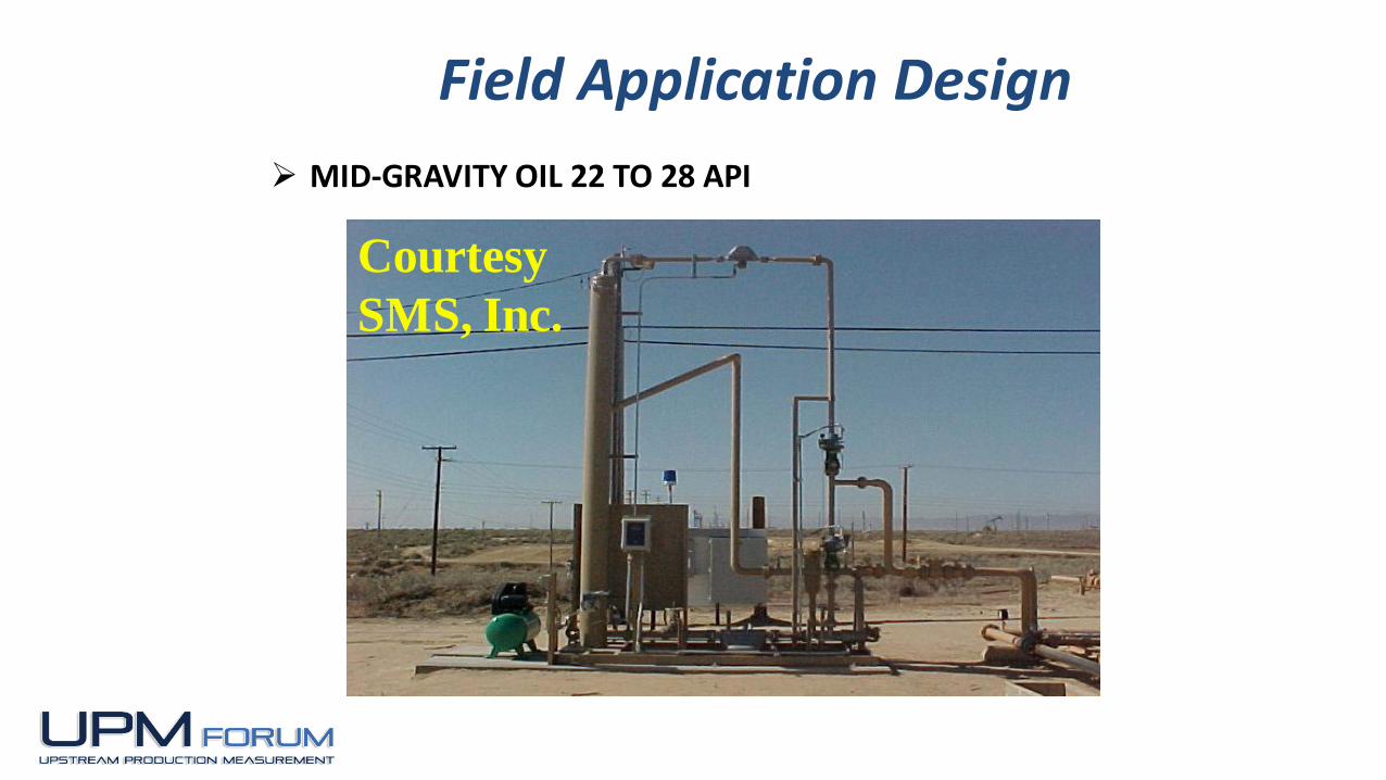
Courtesy
SMS, Inc.
MID-GRAVITY OIL 22 TO 28 API
Field Application Design
1-47
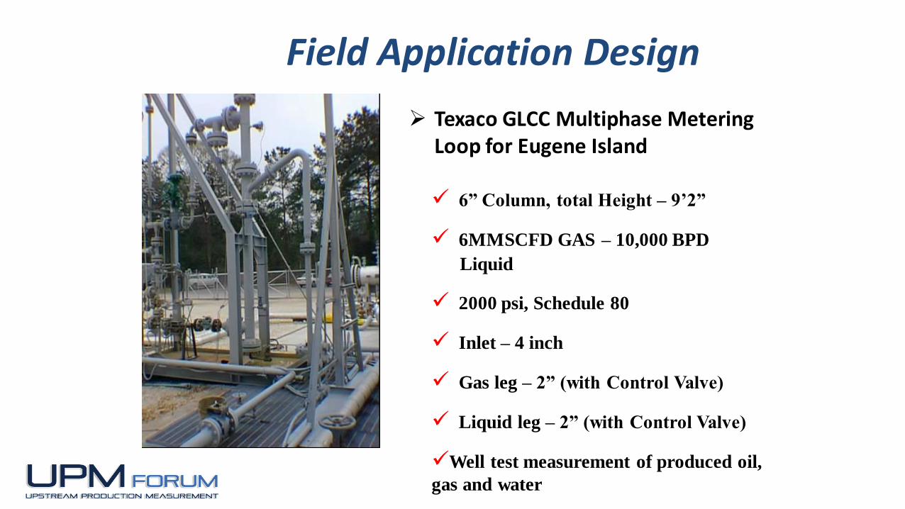
Texaco GLCC Multiphase Metering Loop for Eugene Island
6” Column, total Height – 9’2”
6MMSCFD GAS – 10,000 BPD
Liquid
2000 psi, Schedule 80
Inlet – 4 inch
Gas leg – 2” (with Control Valve)
Liquid leg – 2” (with Control Valve)
Well test measurement of produced oil,
gas and water
Field Application Design

Aera Energy has over 150 units in one field

1-49
12’’ Column
10” Inlet
Coriolis Gas and Liquid
High Gas Rates, Low Liquid
Slug Factors Over 30
Level Control
Temperature: 120º to 250º F.
Field Application Design
12” GLCC - Courtesy SMS,
Inc.
1-50
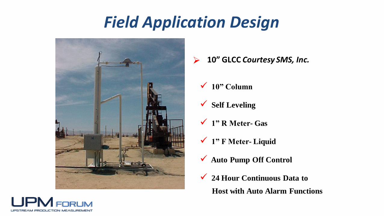
10” GLCC Courtesy SMS, Inc.
10” Column
Self Leveling
1” R Meter- Gas
1” F Meter- Liquid
Auto Pump Off Control
24 Hour Continuous Data to
Host with Auto Alarm Functions
Field Application Design

1-51
Courtesy
SMS, Inc.DUAL GAS RUNS
Unit will Automatically
switch Gas Meters when Flow Rate exceeds Set-Point
1” R Meter- Gas
2” Vortex- Gas
2” F Meter- Liquid
Full level Control
Field Application Design
1-52
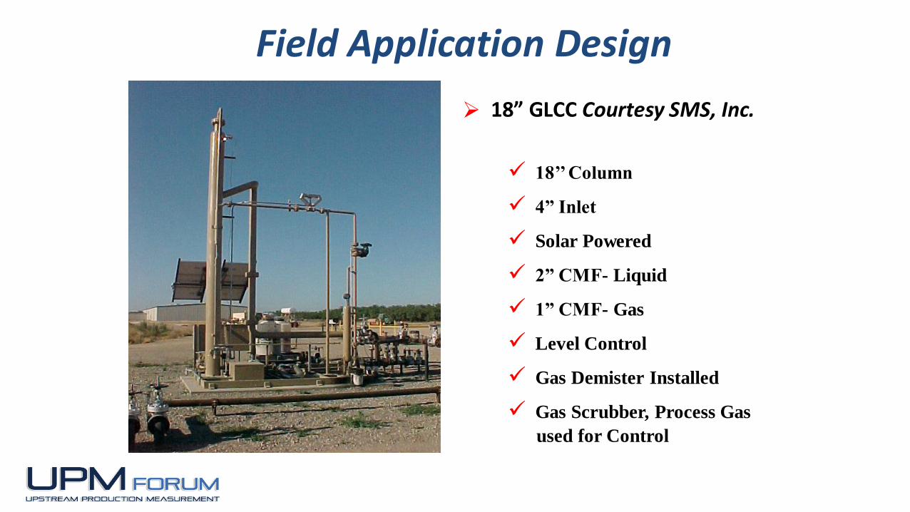
18” GLCC Courtesy SMS, Inc.
18’’ Column
4” Inlet
Solar Powered
2” CMF- Liquid
1” CMF- Gas
Level Control
Gas Demister Installed
Gas Scrubber, Process Gas
used for Control
Field Application Design
1-53
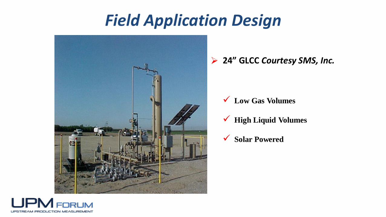
24” GLCC Courtesy SMS, Inc.
Low Gas Volumes
High Liquid Volumes
Solar Powered
Field Application Design

GLCC removes breakout gas from water on Unocal Thailand’s Pailin Platform
Courtesy: NATCO/Cameron
1-55
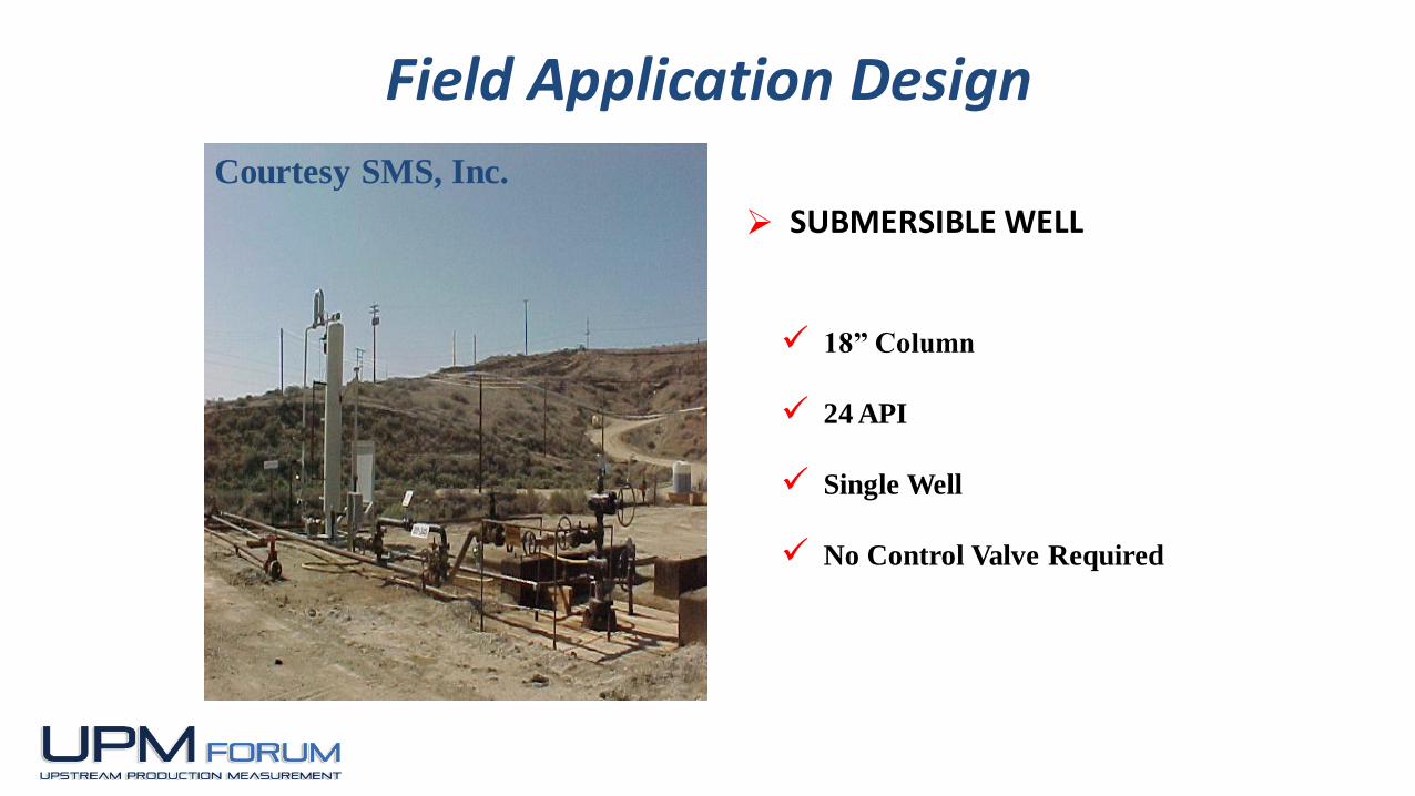
Courtesy SMS, Inc.
18” Column
24 API
Single Well
No Control Valve Required
SUBMERSIBLE WELL
Field Application Design

1-56
GLCC Applications
EXTERNAL PRE-SEPARATION
1-57
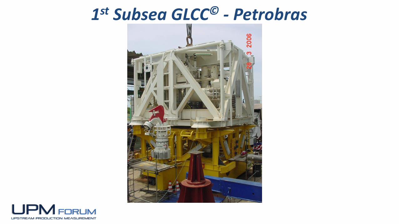
1st Subsea GLCC© - Petrobras

1-58
GLCC© Field Applications and Control Strategies
No.
APPLICATION
CLASSES
Passiv
e C
on
tro
l S
yste
m
Liq
uid
Level
Co
ntr
ol
wit
h L
CV
On
ly
Liq
uid
Level
Co
ntr
ol
wit
h G
CV
On
ly
Hyb
rid
LC
V a
nd
GC
V L
evel
Co
ntr
ol
Pre
ssu
re C
on
tro
l w
ith
GC
V
Liq
uid
Level
Co
ntr
ol
wit
h L
CV
an
d P
ressu
re C
on
tro
l w
ith
GC
V
GV
F C
on
tro
l S
yste
m
Flo
w R
ate
Co
ntr
ol
wit
h L
CV
an
d G
CV
Pre
dic
tive C
on
tro
l o
f G
LC
C
usin
g S
lug
Dete
cti
on
GL
CC
O
pti
mal
an
d A
dap
tive
Co
ntr
ol
- M
ovin
g S
et
po
int
Wate
rcu
t C
on
tro
l S
yste
m
Dp
rati
o c
on
tro
l fo
r L
LH
C
Co
mp
osit
ion
Co
ntr
ol
Ro
bu
st
Co
ntr
ol
Wit
h
Gain
Sch
ed
uli
ng
Mo
dern
Co
ntr
ol
-
Fu
zzy L
og
ic C
on
tro
l
Inte
llig
en
t C
on
tro
l -
Art
ific
ial
Neu
ral
Netw
ork
Do
wn
Str
eam
ON
/OF
F
Pu
mp
Co
ntr
ol
GL
CC
Du
al
Inle
t C
on
tro
l
GL
CC
Vari
ab
le A
rea
Inle
t C
on
tro
l
1 Remote Powerless GLCC Operation X
2 Remote GLCC Operation With Power X X X X X X X X X X X X X X
3 Well Testing (Recombined Flow) X X X X X X X X X X X X X X
4 Bulk Separation (Separator Stand Alone) X X X X X X X X X X X X
5 DownStream Surge Tank Control X X X
6 Separation of Wet Gas (raw Gas Lift) X X X X X X X X X X
7
Separation of Low-Medium GOR
(Liquid Dominated)X X X X X X X X X X X X
8 Separator subjected to Severe Slugging X X X X X X
9
Integrated Separation systems
- 2 Stage GLCCs X X X X X X X X
10 GLCC with Liquid Hydrocyclones X X X X X X X X X X X
11 GLCC Upstream of pumps X X X X X X X X
12 GLCC with Conventional Separators X X X X X X X X X X X X X
13 Subsea Application X X X X X X X X X X X X
14 Downhole Applications X X X X X X X
15
Non-Petroleum Application
- Liquid MeteringX X X X X X X
16
Non-Petroleum Application
- Gas MeteringX X X X X X
17 FREE WATER Knockout with LLCC X X X X X X X X X
18 GLCC/LLCC Integrated System Control X X X X X X X X X X
19 GLCC for Environmental Applications X X X X X X
20
COMPACT Multiphase Separation
System (CMSS) ControlX X X X X X X X X X X X X X X
CONTROL STRATEGIES

1-59
MPFMs (including GLCC© Loop) Testing by Saudi
Aramco in Shaybah Field in 2008
Measurements Compared to SA Testing Skid
Twenty Eight Tests Conducted; Medium to Very
High GOR
Field Testing

1-60
Courtesy Multiphase Systems
Integration (MSI, LLC)
GLCC© MPFM Schematic – Saudi Aramco

1-61
GLCC© MPFM Photograph– Saudi Aramco
Courtesy Multiphase Systems
Integration (MSI, LLC)
1-62
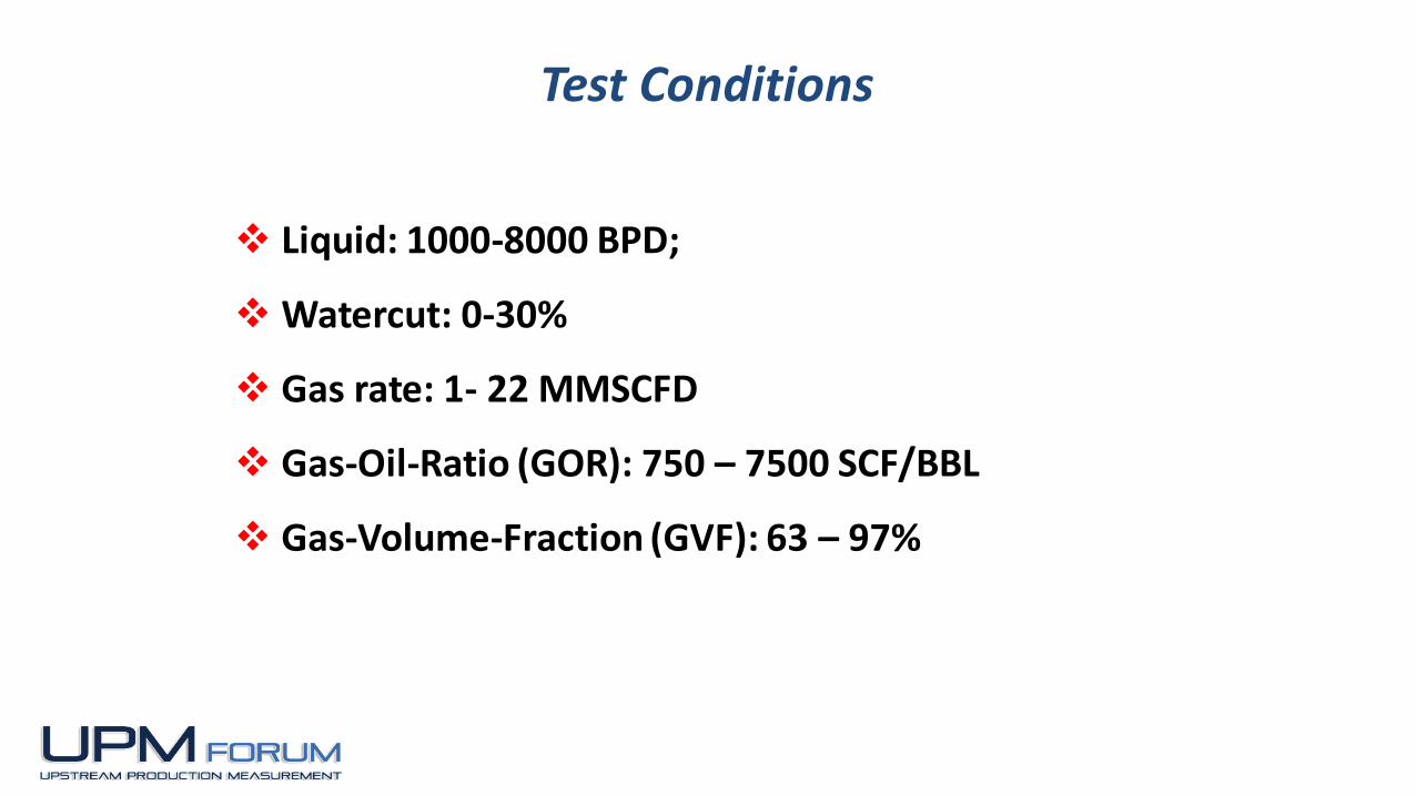
Liquid: 1000-8000 BPD;
Watercut: 0-30%
Gas rate: 1- 22 MMSCFD
Gas-Oil-Ratio (GOR): 750 – 7500 SCF/BBL
Gas-Volume-Fraction (GVF): 63 – 97%
Test Conditions

1-63
GLCC© MPFM Accuracy – Total Liquid Flow Rate
Courtesy Multiphase Systems
Integration, LLC (MSI)

1-64
Courtesy Multiphase Systems
Integration, LLC (MSI)
GLCC© MPFM Accuracy – Oil Flow Rate
1-65
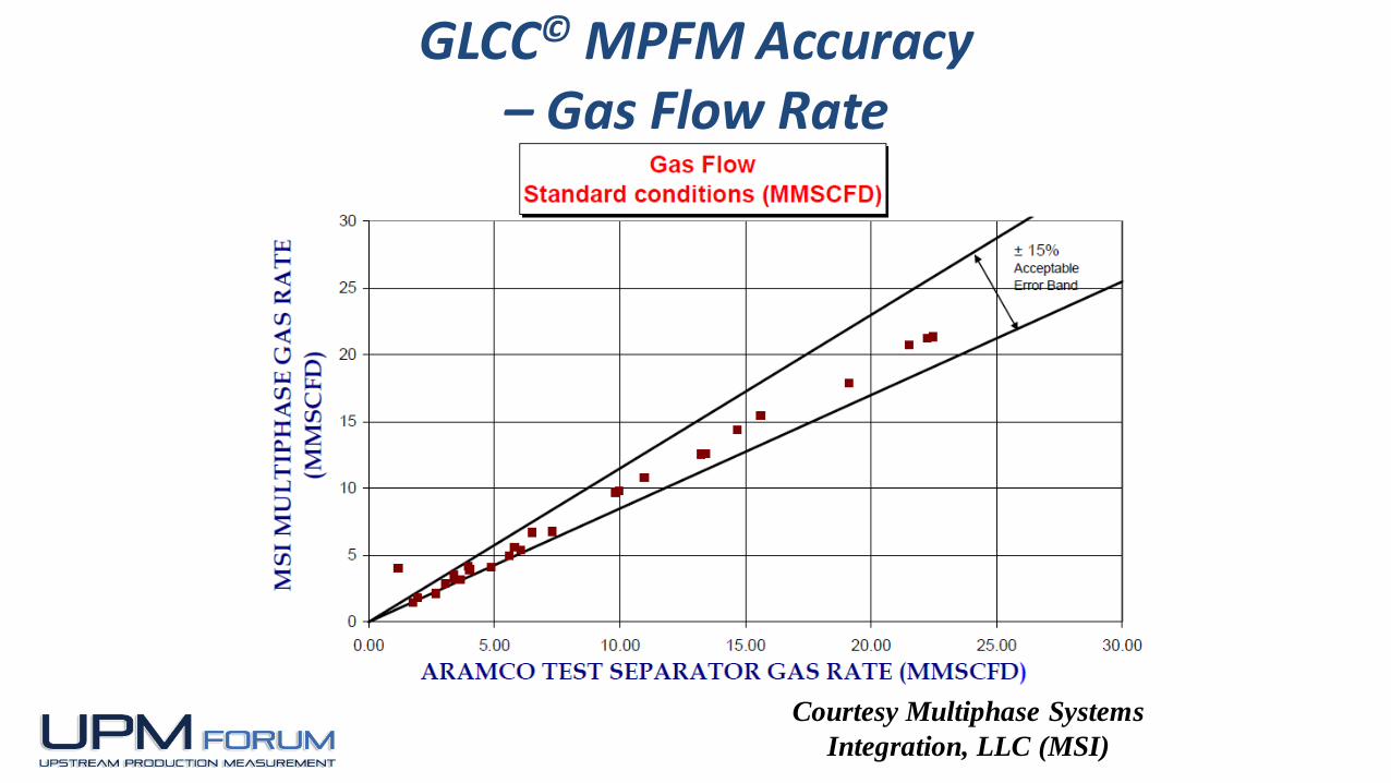
Courtesy Multiphase Systems
Integration, LLC (MSI)
GLCC© MPFM Accuracy – Gas Flow Rate
1-66
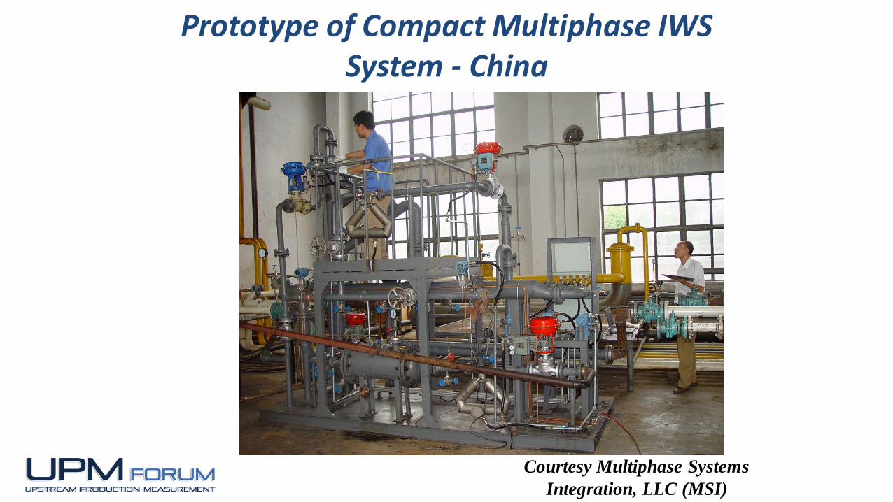
Prototype of Compact Multiphase IWS System - China
Courtesy Multiphase Systems
Integration, LLC (MSI)

1-67
Ref: Xiao, J.J., White, R., Wang, S., and Gomez, L.E., “Inline Water Separation
(IWS) Field Prototype Development and Testing” SPE-137967; Proceedings of
the 2010 SPE Abu Dhabi International Petroleum Exhibition & Conference,
Abu Dhabi, UAE, 1-4 Nov. 2010.
Schematic of InLine Water Separation System (IWS)

1-68
Photograph of InLine
Water Separation
System (IWS) Installed in
the Field
Ref: Xiao, J.J., White, R., Wang, S., and Gomez, L.E., “Inline Water Separation
(IWS) Field Prototype Development and Testing” SPE-137967; Proceedings of
the 2010 SPE Abu Dhabi International Petroleum Exhibition & Conference,
Abu Dhabi, UAE, 1-4 Nov. 2010.

69
IWS Separation Efficiency and Oil in Water Concentration
Ref: Xiao, J.J., White, R., Wang, S., and Gomez, L.E., “Inline Water Separation
(IWS) Field Prototype Development and Testing” SPE-137967; Proceedings of
the 2010 SPE Abu Dhabi International Petroleum Exhibition & Conference,
Abu Dhabi, UAE, 1-4 Nov. 2010.
70

71
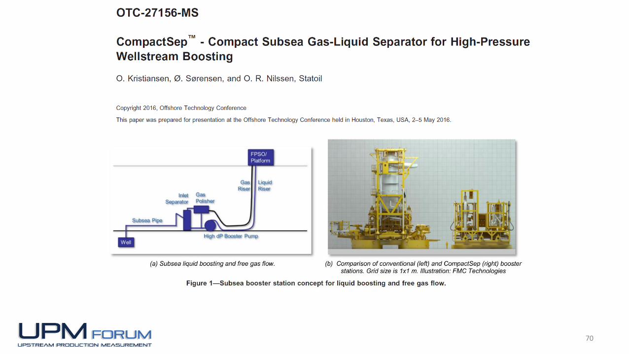
Background and Objectives Subsea separation successfully implemented on the Troll and Tordis fields (Statoil), Pazflor (Total), Marlim (Petrobras), and Perdido and BC-10 (Shell).
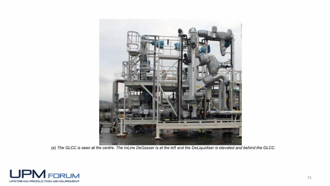
The objective of this work was to qualify a two-stage, compact, inline gas-liquid separation system with full turndown and slug handling capabilities, consisting of already proven components - Gas-Liquid Cylindrical Cyclone (GLCC©) and one InLine DeLiquidiser.
Conducted by Joint Industry Project with Statoil as operator and Chevron, Petrobras, Total, and FMC Technologies as participants
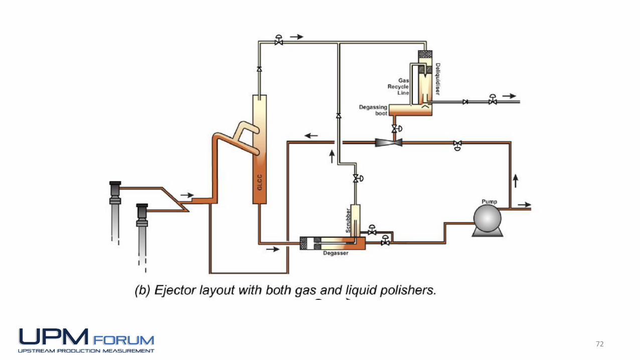
72
73
74
Key Conclusions
The CompactSep system combines the GLCC’s liquid capacity with the DeLiquidiser’s gas capacity. The work developed and qualified an inline separator system with full turndown and slug handling capability at a wide range of realistic conditions.
At design fluid conditions (crude oil, 50 bar): Gas qualities requirement was GVF > 0.995, with measured
result of GVF between 0.995 and 0.999. Liquid quality requirement was GVF < 0.1, with measured
results of GVF between 0.02 and 0.1 The liquid separation efficiency was typically 99 to 99.9%.
1-75
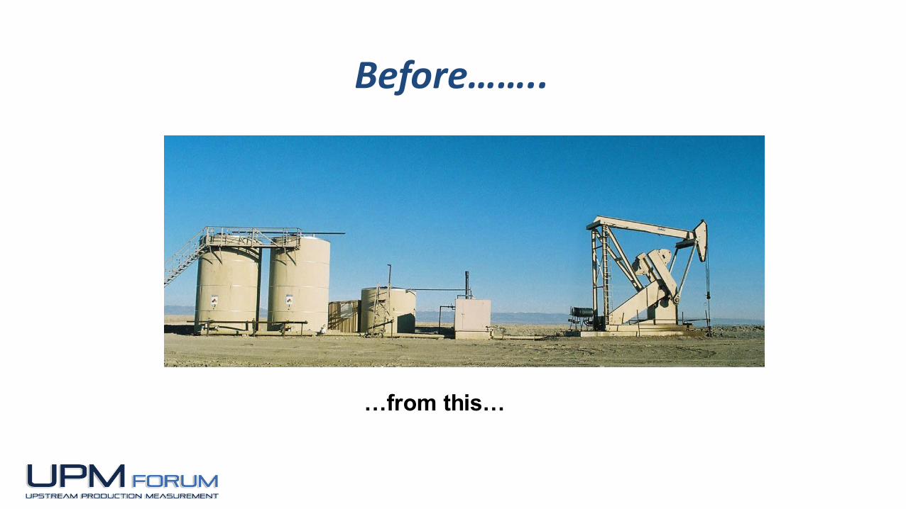
…from this…
Before……..

1-76
…to this !
After……..

1-77
TUSTP Home Pagehttp://www.tustp.org