STATE OF LOUISIANA COASTAL PROTECTION AND RESTORATION...
64
STATE OF LOUISIANA COASTAL PROTECTION AND RESTORATION AUTHORITY _______________________________________________ MID-BRETON SEDIMENT DIVERSION PROJECT STATE PROJECT No. BS-0030 Engineering and Design SCOPE OF SERVICES October 2017
Transcript of STATE OF LOUISIANA COASTAL PROTECTION AND RESTORATION...
STATE OF LOUISIANA COASTAL PROTECTION AND RESTORATION
AUTHORITY _______________________________________________
MID-BRETON SEDIMENT DIVERSION PROJECT
STATE PROJECT No. BS-0030
Engineering and Design SCOPE OF SERVICES
October 2017

Enclosure 1 Scope of Services Page 3 of 64 Final
STATE OF LOUISIANA COASTAL PROTECTION AND RESTORATION AUTHORITY ___________________________________________________________
SCOPE OF SERVICES FOR MID-BRETON SEDIMENT DIVERSION
ENGINEERING AND DESIGN
OCTOBER 2017
Acronyms and Abbreviations .......................................................................................................... 6 1 Introduction............................................................................................................................. 8
Intent ................................................................................................................................ 8 Mississippi River Mid-Basin Sediment Diversion Program Background ....................... 8 Mid-Breton Sediment Diversion Project ......................................................................... 9 BS-0030 Project Features .............................................................................................. 12 1.4.1 River Inlet and Diversion Structure ....................................................................... 15 1.4.2 Conveyance Channel ............................................................................................. 16 1.4.3 Gated Back Structure ............................................................................................. 16 1.4.4 Outfall Channel ..................................................................................................... 16 1.4.5 Site Drainage ......................................................................................................... 16 1.4.6 LA-39 Highway Crossing ...................................................................................... 16 1.4.7 Relocation of Utilities ............................................................................................ 17 1.4.8 Dredge Material Placement Area .......................................................................... 17
2 General Design Administrative Services .............................................................................. 18 General Project Engineering .......................................................................................... 18 Design Project Accounting ............................................................................................ 19 Design Project Schedule ................................................................................................ 20 Information Management Plan ...................................................................................... 20 Design Quality Assurance/Quality Control (QA/QC) ................................................... 21 Project Health and Safety Plan ...................................................................................... 21 Project Risk Register ..................................................................................................... 21 Design P6 Schedule and Schedule of Values ................................................................ 22
3 Design Services Required ..................................................................................................... 23 Civil Engineering........................................................................................................... 25 Coastal Engineering....................................................................................................... 25 Hydraulics Engineering Services................................................................................... 26 Hydrology and Drainage Engineering ........................................................................... 27 Geotechnical Engineering ............................................................................................. 27 Surveying Services ........................................................................................................ 27
Enclosure 1 Scope of Services Page 4 of 64 Final
Structural/Bridge Engineering ....................................................................................... 28 Highway and Traffic Engineering ................................................................................. 29 Environmental and Permitting Services ........................................................................ 29 Mechanical Engineering ................................................................................................ 30 Electrical Engineering ................................................................................................... 30 Instrumentation/Controls Engineering .......................................................................... 31
4 Scope of Work, Milestones and Major Deliverables ............................................................ 33 Design Milestones and Major Deliverables................................................................... 33 4.1.1 Milestone A: Basis of Design (15%) Completion ................................................. 34 4.1.2 Milestone B: 30% Design Completion Requirements ........................................... 34 4.1.3 Milestone C: 60% Design Completion Requirements ........................................... 34 4.1.4 Milestone D: 90% Design Completion Requirements........................................... 34 4.1.5 Milestone E: 100% Design Requirements ............................................................. 35 Scope of Work - Phase 1: Conceptual Design ............................................................... 35 4.2.1 Project Work Plan Development ........................................................................... 35 Site Investigation, Data Collection, and CPRA Model Review ........................................... 35 4.2.2 Basis of Design (15%) Development .................................................................... 36 4.2.3 Coordination with TPC .......................................................................................... 40 4.2.4 Coordination on CMAR Basis of Design Cost Estimate ....................................... 40 Scope of Work - Phase 2: Detailed Design ................................................................... 41 4.3.1 30% Design ........................................................................................................... 41 4.3.2 60% Design ........................................................................................................... 42 4.3.3 90% Design ........................................................................................................... 42 4.3.4 100% Design ......................................................................................................... 42 4.3.5 Coordination with TPC .......................................................................................... 43 4.3.6 Coordination on CMAR Cost Estimate ................................................................. 43 4.3.7 Detailed Design Reports, Modeling and Studies ................................................... 43 CMAR Pre-Construction Support Services ................................................................... 50
5 Reference Documents ........................................................................................................... 53 Appendix A: Section 408 Submittal Package Requirements for MVN ........................................ 54
Figures Figure 1: Mississippi River Mid-Basin Sediment Diversion Program Location ............................. 9 Figure 2: BS-0030 Location Boundary for Diversion Footprint ................................................... 15

Enclosure 1 Scope of Services Page 5 of 64 Final
Tables Table 1: Summary of CPRA Position on Design Parameters ................................................. 12-14 Table 2: Mid-Breton Sediment Diversion Project Design WBS ................................................... 21
Enclosure 1 Scope of Services Page 6 of 64 Final
Acronyms and Abbreviations AHP Above Head of Passes
ATR Agency Technical Review
BOD Basis of Design
BODR Basis of Design Report
CFS Cubic Feet per Second
CMAR Construction Manager at Risk
CPRA Coastal Protection and Restoration Authority
DDR Design Documentation Report
DOTD Louisiana Department of Transportation and Development
E&D Engineering and Design
EIS Environmental Impact Statement
El Elevation
ESA Environmental Site Assessment
FWCA Fish & Wildlife Coordination Act
GEBF Gulf Environmental Benefit Fund
GMP Guaranteed Maximum Price
HSDRRSDG Hurricane and Storm Damage Risk Reduction System Design Guidelines
HVAC Heating, Ventilation, and Air Conditioning
I&C Instrumentation & Controls
I.C.E. Independent Cost Estimator
ITR Independent Technical Review
LAPELS Louisiana Professional Engineering and Land Surveying Board
LCA Louisiana Coastal Area
MBSD Mid-Barataria Sediment Diversion
MBrSD Mid-Breton Sediment Diversion
MPRSA Marine Protection Research & Sanctuaries Act
MRMBSDP Mississippi River Mid-Basin Sediment Diversion Program
MR Mississippi River
MRL Mississippi River Levee
NEPA National Environmental Policy Act
NFL Non-Federal Levee
Enclosure 1 Scope of Services Page 7 of 64 Final
NFWF National Fish and Wildlife Foundation
NRDA Natural Resource Damage Assessment
NTP Notice to Proceed
O&M Operations and Maintenance
OMRR&R Operations, Maintenance Repair, Replacement and Rehabilitation
PLS Professional Land Surveyor
PMIS Program Management Information System
PMT Program Management Team
POC Point of Contact
“Program” Mississippi River Mid-Basin Sediment Diversion Program
QA
QC
Quality Assurance
Quality Control
QC Quality Control
RFI Request for Information
ROE Right of Entry
ROW Right of Way
SAR Safety Assurance Review
SCADA Supervisory Control & Data Acquisition
SOV
SUE
SWR
TPC
Schedule of Values
Subsurface Utility Engineering
Sediment to Water Ratio
Third Party Contractor
TWIG The Water Institute of the Gulf
USACE US Army Corps of Engineers
WBS Work Breakdown Structure
WRDA Water Resources Development Act
WSE Water Surface Elevation

Enclosure 1 Scope of Services Page 8 of 64 Final
1 Introduction Intent
The Coastal Protection and Restoration Authority of Louisiana (CPRA) has established the Mississippi River Mid-Basin Sediment Diversion Program (Program or MRMBSDP) which is comprised of the Mid-Barataria Sediment Diversion Project (MBSD) and the Mid-Breton Sediment Diversion (MBrSD) Projects. CPRA is seeking to select a firm and sub-consultants (DESIGN TEAM) to provide project management, engineering and design services for the diversion. This design is a part of the overall Construction Management at Risk (CMAR) approach to designing and constructing the Diversion. The project is located on the east side of the Mississippi River near river mile 68 above Head of Passes (AHP). The intent of the project is to capture sediment laden water from the Mississippi River and then convey that captured water and sediment to the Breton Sound Basin. This scope of services document is for the design services associated with BS-0030; the MBSD Project is not part of this Scope.
Mississippi River Mid-Basin Sediment Diversion Program Background
The Mid-Breton Diversion is a critical near term restoration feature recommended for implementation in Louisiana’s Coastal Master Plan that was approved by the Louisiana State Legislature in May 2012. The Diversion is expected to restore significant habitat in the Breton Sound Basin, including fresh, intermediate, and brackish marshes by re-introducing the sediment and nutrients which historically built and maintained the affected area.
CPRA identified sediment diversions as one of the types of projects critical to the restoration of Louisiana’s coastal ecosystem. By reconnecting the river, these projects will reestablish the natural deltaic processes to build, sustain and maintain wetlands in accordance with the Louisiana Comprehensive Master Plan for a Sustainable Coast (Coastal Master Plan), who’s overarching objectives are:
• Flood Protection: Reduce economic losses from storm surge based flooding to residential, public, industrial, and commercial infrastructure
• Natural Processes: Promote a sustainable coastal ecosystem by harnessing the natural processes of the system
• Coastal Habitats: Provide habitats suitable to support an array of commercial and recreational activities coast wide
• Cultural Heritage: Sustain the unique cultural heritage of coastal Louisiana by protecting historic properties, traditional living cultures, and their ties and relationships to the natural environment
• Working Coast: Promote a viable working coast to support regionally and nationally important businesses and industries
In November 2015, upon the conclusion of several in-depth studies and modeling efforts, CPRA decided to initiate further Engineering and Design phases for the MBSD and the MBrSD. To assist with timely efforts for procurement and management of design, environmental requirements and construction of the MBSD and MBrSD Projects, the CPRA created the Mississippi River Mid-Basin Sediment Diversion Program (Program or MRMBSDP).
The funding for the planning, permitting, engineering and design, as well as construction for the Program is anticipated to come from the National Fish and Wildlife Foundation (NFWF).

Enclosure 1 Scope of Services Page 9 of 64 Final
The MRMBSDP has diversion projects located on the west and east banks of the Mississippi River as so indicated in Figure 1.
Figure 1: Mississippi River Mid-Basin Sediment Diversion Program Location
The Mississippi River Mid-Basin Sediment Diversion Program is comprised of two projects. The Diversion located on the east side of the Mississippi River near river mile 68 AHP, is planned to divert water from the Mississippi River to the Breton Sound Basin. The MBSD is located on the west bank of the Mississippi River at river mile 60.7 AHP, is planned to divert water from the Mississippi River to the Barataria Basin. Both diversions are to be designed to capture high amounts of sediment and freshwater carried downstream by the river during flood events and deliver them into wetlands and open water areas on the far side of hurricane levees on the east and west banks of the river. Sediment is also anticipated to be pulled off of the nearby sand bars located in the vicinity of the diversions during high river events. The sediment deposited as a result of these projects is intended to build new land and to nourish existing wetlands in both areas.
Mid-Breton Sediment Diversion Project The Diversion is a riverine sediment diversion being designed to strategically reintroduce sediment and freshwater inputs into the Breton Sound Basin. The proposed project location is on the east bank of the Mississippi River near Wills Point, near river mile 68 AHP (Figure 1). The project is anticipated to include an inlet channel, a gated structure at the Mississippi River Levee (MRL), a conveyance channel, interior drainage improvements, a structure/connection to the non-federal back levee, and highway alignment accommodations.
The Diversion has a history in restoration planning in coastal Louisiana. The Mid-Breton Sediment Diversion Project (BS-0030), previously referred to as the ‘Medium Diversion at White Ditch (MDWD) Project’ originated with the Louisiana Coastal Area (LCA) Ecosystem Restoration Study and was later authorized as a Water Resources and Development Act (WRDA) 2007 project. The State of Louisiana, acting through the CPRA, was the non-Federal sponsor for the LCA project,

Enclosure 1 Scope of Services Page 10 of 64 Final
and the US Army Corps of Engineers (USACE) was the federal sponsor that acted as the technical planning lead. The feasibility study resulted in a Chief’s Report (signed December 31, 2010) containing a Recommended Plan to construct a Mississippi River diversion in the vicinity of White Ditch.
The project was recommended by CPRA in fall 2015 to move forward to the preliminary engineering and design phase and was included in the 2017 Coastal Master Plan (CPRA 2017). CPRA has performed limited studies and modeling to determine a recommended location of the diversion. Little to no field data collection has been performed for the previous work. A conceptual design has not been performed on this project. Relevant studies, modeling results and reviews are provided at http://coastal.la.gov/mid-breton-existing-documents/.
The vision for the Diversion encompasses restoration of the natural deltaic and sedimentation processes along the Mississippi River near river mile 68 AHP, near Wills Point. The purpose of the Diversion is to divert sediment-laden Mississippi River water into the Breton Sound Basin to re-establish the connection between the Mississippi River and the basin to build, sustain, and maintain land. CPRA proposes to construct the diversion intake and control structure through the MRL on the east side of the Mississippi River near river mile 68 AHP, in Plaquemines Parish, LA, and to construct the diversion outfall through the non-federal levee into the Breton Sound Basin to allow sediment-laden water from the Mississippi River to flow into the Breton Sound Basin.
Goals and features of the project as provided include:
• Reconnect and reestablish the natural or deltaic sediment deposition process between the Mississippi River and the Breton Basin.
• Reduce land loss rates and sustain wetlands in the Breton Basin through the delivery of sediment, freshwater, and nutrients from the Mississippi River.
• Use, as an initial basis of design, a peak flow capacity of approximately 35,000 cubic feet per second (cfs) from the Mississippi River Levee (“MRL”) through the diversion structure and conveyance channel to the Breton Basin. The final diversion flow rates may be adjusted with CPRA approval based on results of modeling and design.
• Design the diversion intake and control structure, conveyance channel, flood protection features and any additional necessary appurtenances to maximize sediment capture, maximize flow efficiency, and allow for operations adaptability, while minimizing Operations, Maintenance, Repair, Replacement and Rehabilitation.
• Meet state and federal design criteria and environmental compliance requirements as required to achieve project regulatory approval.
• Maintain the current level of flood risk reduction of the MRL and Plaquemines Parish non-federal levee system.
• Assist CPRA and the Program Team in developing an operational plan for the diversion structure.
The project will be subject to USACE Section 404/10 regulatory programs, and 33 United States Code Section 408 permissions to modify federal projects, which includes the MRL. CPRA will submit a Section 404/10 permit application to the USACE. CPRA will procure the services of a third party contractor (TPC) firm to prepare the Environmental Impact Statement (EIS) as required for National Environmental Policy Act (NEPA) compliance. The EIS work and efforts will be progressing concurrently with the development of the BS-0030 detailed design. The DESIGN TEAM will be expected to provide information and deliverables to support the TPC. CPRA will initiate and lead coordination for Section 408 approval, the DESIGN TEAM will have deliverables for Section 408 submittals.
The DESIGN TEAM is to prepare complete and coordinated Construction Documents that detail the design in order to procure, permit, and construct the project. The Program Team is going to

Enclosure 1 Scope of Services Page 11 of 64 Final
utilize a CMAR model to deliver this project. Under a separate contract, CPRA will procure the CMAR who will be collaborating with the DESIGN TEAM throughout the design phase and providing input to the design pertaining to constructability, temporary works, cost, and schedule. This BS-0030 E&D Scope of Services will be revised as required during the contract negotiations with the selected CMAR firm. The CMAR firm is anticipated to receive their Notice to Proceed (NTP) during the draft phase of the BOD prepared by the DESIGN TEAM. Refer to Section 4.4 for more information regarding the CMAR.
The DESIGN TEAM who prepares the construction drawings and specifications must be experienced in the necessary technical area(s) and be of the appropriate design discipline required for the proposed project. CPRA requires that all construction drawings and specifications be under the seal of licensed professional engineers (and land surveyors) who are under the responsible charge of a licensed professional Engineer of Record, authorized by Louisiana law to apply the seal in accordance with the laws and rules of the State Board of Registration for Professional Engineers and Land Surveyors (LAPELS).
Enclosure 1 Scope of Services Page 12 of 64 Final
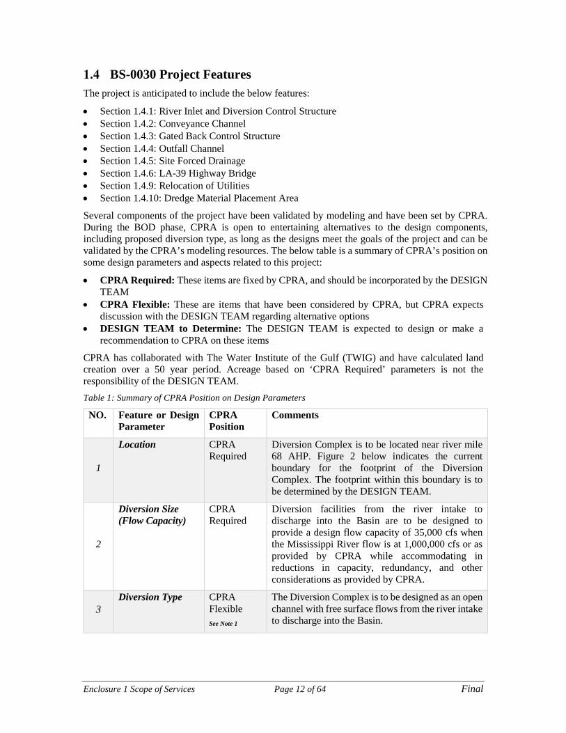
BS-0030 Project Features The project is anticipated to include the below features:
• Section 1.4.1: River Inlet and Diversion Control Structure • Section 1.4.2: Conveyance Channel • Section 1.4.3: Gated Back Control Structure • Section 1.4.4: Outfall Channel • Section 1.4.5: Site Forced Drainage • Section 1.4.6: LA-39 Highway Bridge • Section 1.4.9: Relocation of Utilities • Section 1.4.10: Dredge Material Placement Area
Several components of the project have been validated by modeling and have been set by CPRA. During the BOD phase, CPRA is open to entertaining alternatives to the design components, including proposed diversion type, as long as the designs meet the goals of the project and can be validated by the CPRA’s modeling resources. The below table is a summary of CPRA’s position on some design parameters and aspects related to this project:
• CPRA Required: These items are fixed by CPRA, and should be incorporated by the DESIGN TEAM
• CPRA Flexible: These are items that have been considered by CPRA, but CPRA expects discussion with the DESIGN TEAM regarding alternative options
• DESIGN TEAM to Determine: The DESIGN TEAM is expected to design or make a recommendation to CPRA on these items
CPRA has collaborated with The Water Institute of the Gulf (TWIG) and have calculated land creation over a 50 year period. Acreage based on ‘CPRA Required’ parameters is not the responsibility of the DESIGN TEAM. Table 1: Summary of CPRA Position on Design Parameters
NO. Feature or Design Parameter
CPRA Position
Comments
1
Location CPRA Required
Diversion Complex is to be located near river mile 68 AHP. Figure 2 below indicates the current boundary for the footprint of the Diversion Complex. The footprint within this boundary is to be determined by the DESIGN TEAM.
2
Diversion Size (Flow Capacity)
CPRA Required
Diversion facilities from the river intake to discharge into the Basin are to be designed to provide a design flow capacity of 35,000 cfs when the Mississippi River flow is at 1,000,000 cfs or as provided by CPRA while accommodating in reductions in capacity, redundancy, and other considerations as provided by CPRA.
3 Diversion Type CPRA
Flexible See Note 1
The Diversion Complex is to be designed as an open channel with free surface flows from the river intake to discharge into the Basin.

Enclosure 1 Scope of Services Page 13 of 64 Final
4 Gated Intake Structure
CPRA Required
The Diversion Complex is to be designed with a gated intake structure at the MR Levee. See item number 12 for gate type.
5
Operational Plan CPRA Flexible
CPRA will provide the general criteria for when the Diversion Control Gates will be either open or closed. The DESIGN TEAM will be required to provide input regarding operational triggers for opening the diversion.
6
Requirements to Accommodate lower base flow for maintenance
CPRA Flexible
See Note 2
CPRA to provide the requirement for maintaining a minimum diversion base flow when River flows are below the operational trigger for opening the diversion. This flow will be determined in coordination with CPRA modeling.
7 Traffic Crossing Structure type
DESIGN TEAM to Determine
The LA 39 Highway crossing could be achieved with a bridge. The DESIGN TEAM may provide alternative recommendations.
8
Diversion River Intake Sill Elevation
DESIGN TEAM to Determine
The DESIGN TEAM should provide a recommendation on the optimum intake sill elevation in coordination with CPRA.
9
Minimum Diversion flow Velocity in Channel
DESIGN TEAM to Determine
The DESIGN TEAM should provide recommendations for the minimum diversion flow velocities such that siltation does not occur within the conveyance channel.
10
Gated Back structure at non-federal levee
DESIGN TEAM to Determine
The DESIGN TEAM should make a recommendation regarding a potential gated back structure at the non-federal levee.
If it is determined that a gated back structure is required, the DESIGN TEAM is to prepare a Back Structure Gate Operation Plan that will need to be coordinated with the Overall Diversion Operational Plan and adhere to the guidance and non-federal back levee requirements.
11
Channel alignment and orientation
DESIGN TEAM to Determine
The DESIGN TEAM should make a recommendation regarding the alignment and orientation of the diversion structure from the River Intake to the Outfall into the Basin
12
Diversion Control Gate type
DESIGN TEAM to Determine
The DESIGN TEAM is responsible for determining the type of control gate to be used, as long as it maintains open channel and free surface flows from the river to the discharge.

Enclosure 1 Scope of Services Page 14 of 64 Final
13 Scour Protection DESIGN
TEAM to Determine
The DESIGN TEAM should evaluate cost effective alternatives for scour protection of the conveyance channel and outfall.
14
Diversion Control Structure position with respect to the MRL
DESIGN TEAM to Determine
CPRA would consider having the Control Structure be setback or in line with the MR Levee.
15
River intake shape, outlet shape, and structure configuration
DESIGN TEAM to Determine
The DESIGN TEAM is responsible for designing the river intake structure to maximize sediment to water ratios (SWRs) for the range Diversion Flows. The diversion shall be designed so that it operates at maximum capacity when the MR is at 1,000,000 cfs for a period of time to be provided by CPRA. Redundancy may be considered taking into account the impact sedimentation could have over the life of the project.
16
Intake/Outlet Erosion Protection
DESIGN TEAM to Determine
The DESIGN TEAM is responsible for designing the river intake so as to prevent erosion of the Mississippi River bottom upstream and downstream from the Intake Structure. Design should also minimize downstream shoaling.
The outfall into the Basin is to be designed so as to minimize erosion and scour in the areas adjacent to the Diversion Discharge Outfall.
17
Method to Address the Interior Drainage
DESIGN TEAM to Determine
The DESIGN TEAM to determine the impact to the existing drainage layout is to be addressed. CPRA may consider a new pump station or other options such as a siphon structure under the Diversion Channel, a drop structure.
Note 1: CPRA will at its sole discretion review alternative conveyance solutions with the contracted Design Team during the BOD phase of the contract. Alternative solutions will be limited to proven engineering designs which have been constructed and are operational. These alternatives may be presented in the project experience section of the Request for Statement of Interest & Qualifications response.
Note 2: DESIGN TEAM will determine minimum diversion flow velocities such that siltation is minimized within the conveyance channel. Operation and maintenance considerations for the conveyance channel will be developed as part of the design to support life cycle costing and sedimentation management.
Enclosure 1 Scope of Services Page 15 of 64 Final
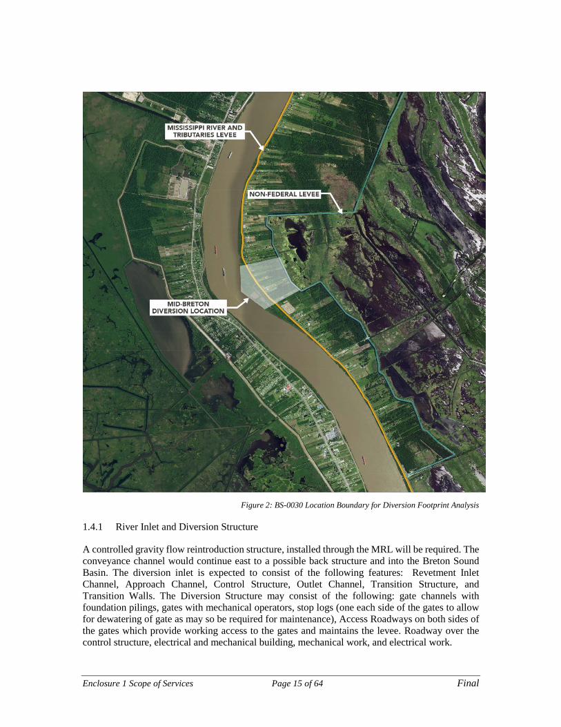
Figure 2: BS-0030 Location Boundary for Diversion Footprint Analysis
1.4.1 River Inlet and Diversion Structure
A controlled gravity flow reintroduction structure, installed through the MRL will be required. The conveyance channel would continue east to a possible back structure and into the Breton Sound Basin. The diversion inlet is expected to consist of the following features: Revetment Inlet Channel, Approach Channel, Control Structure, Outlet Channel, Transition Structure, and Transition Walls. The Diversion Structure may consist of the following: gate channels with foundation pilings, gates with mechanical operators, stop logs (one each side of the gates to allow for dewatering of gate as may so be required for maintenance), Access Roadways on both sides of the gates which provide working access to the gates and maintains the levee. Roadway over the control structure, electrical and mechanical building, mechanical work, and electrical work.

Enclosure 1 Scope of Services Page 16 of 64 Final
The design river water surface elevation (WSE) should be based on historical river crests, tidal influences and allowance for sea level rise as utilized and developed by CPRA during the project base modeling. The Gate Operation plan should have provisions for operating the diversion when the gates are fully opened, fully closed or partially opened. The intake structure(s) and the conveyance channel should also accommodate a low base flow for basin maintenance purposes; parameters will be supplied by CPRA.
1.4.2 Conveyance Channel
The conveyance channel is to be designed to convey the sediment-laden river water from the Control Structure to the Basin without overtopping the guide levees with enough velocity to prevent buildup of siltation in the channel and with protection against scour. The DESIGN TEAM shall determine the configuration of the conveyance channel design based on hydraulic and geotechnical considerations. Long-term scour protection of the conveyance channel should be provided as necessary. Channel configuration should consider the maximum conveyance and minimum base flows required in the channel based on the CPRA modeling and the project goals.
1.4.3 Gated Back Structure
A gated back structure may or may not be required through the non-federal levee, on the downstream end of the conveyance channel. The design may consist of a transition, back structure with gated channels and a dredged transition into the basin. The DESIGN TEAM, in coordination with the Program Team, is to evaluate the need for a back structure.
1.4.4 Outfall Channel
The design is expected to have an Outfall Channel that will disperse the channel flow into the basin. The outfall is a dredged channel extending into the basin beyond the non-federal levee.
1.4.5 Site Drainage
The new Conveyance Channel will divide the current drainage area. Many options exist for handling the storm water from the north of the Conveyance Channel. The DESIGN TEAM should evaluate the need for a new pump station, a drop structure, or a siphon structure/pipe(s). CPRA is also open to the proposal of new concepts to accommodate the permanent impact to site forced drainage that this diversion will create.
1.4.6 LA-39 Highway Crossing
Louisiana Highway LA-39 is a north–south state highway that serves Plaquemines Parish. The new Conveyance Channel requires modifications to the existing highway. All associated roadway and bridge work is to be designed and constructed in accordance with Louisiana Department of Transportation and Development (DOTD) design standards and construction specifications and DOTD Bridge Load Rating requirements and in coordination with DOTD. A DOTD bridge load rating and report is required based on the final bridge plans and the as-built bridge plans. CPRA is open to proposed concepts to accommodate the permanent impact to traffic that this diversion will create such as the incorporation of the highway crossing into the diversion gate structure.

Enclosure 1 Scope of Services Page 17 of 64 Final
1.4.7 Relocation of Utilities
The DESIGN TEAM is responsible for identifying all utilities in the project area and for coordinating with and accommodating all utilities that will be impacted by the diversion. These utilities should be assumed to be required to be relocated prior to the start of construction of the diversion complex. Details of these potential relocations are to be coordinated by the DESIGN TEAM with the utility companies and the CMAR planned construction activities.
1.4.8 Dredge Material Placement Area
This element is for the placement of materials hydraulically and mechanically dredged for the construction of the Diversion Complex or other areas where large scale excavation may occur. The amount of available material to be placed in the Dredge Fill Area will depend on the cut and fill balance of the Conveyance Channel as designed. After consultation with CPRA the DESIGN TEAM shall prepare a plan for the placement, reuse, and/or disposal of dredged material from the conveyance channel, and the potential use of dredged material in applications outside of the Diversion complex.
Enclosure 1 Scope of Services Page 18 of 64 Final
2 General Design Administrative Services General Design Administrative Services for this contract will consist of, but not be limited to, the following:
General Project Engineering DESIGN TEAM will perform engineering analysis and design and prepare the BOD (15%), 30%, 60%, 90%, and 100% submittal packages. Deliverables will be signed and sealed by a registered professional engineer in the State of Louisiana as per LAPELS requirements.
As it pertains to the project features listed in Section 1.4, the DESIGN TEAM shall provide personnel and equipment to perform engineering and design services including, but not limited to:
• General engineering studies • Analysis and manipulation of data sets and GIS software • Project scoping • Technical document development and review • Report preparation and presentation • Preparation of construction documents including plans, specifications and bid packages • Quantity generation to support external and internal construction cost estimates • Engineering construction cost estimates • Technical presentations • Interfacing with all engineering and scientific disciplines • Coordination with and management of USACE 404 permit and Section 408 permission team • Coordination support for information, reports and modeling in support of the EIS progression • Collaboration and coordination with the CMAR
The DESIGN TEAM will implement design and quality assurance processes in alignment with the guidelines established by the Program. The DESIGN TEAM will work collaboratively with CPRA and CMAR consultants to deliver work products consistent with the budget, schedule, scope, and quality guidelines of the Program. The DESIGN TEAM will provide a weekly status update which will show progress and meet the requirements outlined in Section 2.2 and Section 2.3. This weekly status report is a written progress report provided to CPRA that provides update on schedule, deliverables, progress, issues and issue resolution activities.
The Program has established the goals of exemplary cost management, effective change management, and strategic engagement with stakeholders. CPRA expects regular communication regarding project status and sound cost and change control management. CPRA will effectively and transparently engage with the DESIGN TEAM through the following:
• Earned Value Management – Earned Value Management techniques will be implemented on the Program to provide cost and schedule performance metrics in an industry standard format
• Program Management Information System (PMIS) – Web based Program dashboard will provide constant access to performance data, including cost and schedule
• Milestone and Deliverable Reporting – Reporting on deliverables and achievements against milestones will be provided
• Document Access – Access to key documents and deliverables will be provided through a SharePoint website, giving DESIGN TEAM constant and transparent access to information
• Stage Gate Reviews – CPRA will engage DESIGN TEAM in a series of planned stage gate reviews. The stage gate review process is included in the Program Management scope of work

Enclosure 1 Scope of Services Page 19 of 64 Final
as the stage gates serve as a mechanism to ensure consistent delivery aligned with funding availability, stakeholder support, and permitting constraints
The DESIGN TEAM will provide physical facilities for key staff during the entire design phase (phased to the needs of the project). Key staff are considered to be the following: an estimated peak of twenty-five (25) design team members, five (5) PMT members, and a minimum of five (5) members of the CMAR Team. These facilities will we required to have telecom/networking capabilities. The facilities are expected to be in East Baton Rouge Parish (within a reasonable driving distance to the CPRA headquarters) and should include the following minimum conference rooms (with A/V) to accommodate milestone workshops and meetings: One forty (40) person conference room; two twelve (12) person conference rooms. The timing of CMAR key personnel collocation will be determined in the CMAR solicitation and contract negotiation processes.
A specific list of deliverables, with reporting format requirements, will accompany each Task Order when issued. All deliverables shall be accompanied by a typed Letter of Transmittal.
Deliverables
• Weekly Progress Reports • Plans, Specifications, Quantities, Estimates, and Reports as described in Section 4
Design Project Accounting The BS-0030 design is funded by NFWF, and the project requires that many sequential and continuous coordination and design activities shall be occurring at all times. Time and effort shall be required to review, assemble, document, and present the invoices to CPRA to ensure the invoices are clear, correct, ready for processing, and provide the information needed for the NFWF financial accounting requirements. A series of meetings and workshops may be required at the initiation of the project to review invoicing standards, requirements and protocols.
In addition to regular communication between NFWF and CPRA, the Program Management Team (PMT) plans to regularize the payment request submittal to NFWF. It is anticipated that submittals will be made on a monthly basis and include all costs that have actualized in the state accounting system during the period. The Program will work with the DESIGN TEAM to align invoicing closing dates to a standard day of the month to further simplify the NFWF payment requests. Invoicing is expected to align to the Program Work Breakdown Structure (WBS). The invoice shall include a narrative of work accomplished during the invoice period. The PMT will provide a standard invoice cover sheet which will capture all details associated with Project Controls reporting.
The DESIGN TEAM shall coordinate and compile with all TEAM sub-consultants on a monthly basis to ensure timely and accurate invoicing. The DESIGN TEAM shall comply with all CPRA contracting protocols and associated forms.
Weekly progress reports are generated by the PMT. As part of the weekly report from the DESIGN TEAM, the DESIGN TEAM will be expected to provide a financial report for PMT input into the overall progress reporting. Specific requirements will be provided upon project kickoff.
Deliverables
• Monthly invoices with progress narrative • Weekly Financial Reports (Part of Weekly Report)

Enclosure 1 Scope of Services Page 20 of 64 Final
Design Project Schedule The PMT will oversee regular schedule updates and progress tracking. It is anticipated that schedule submittals will be made on a monthly basis or as needed and will be done in conjunction with the Program Controls Manager and the Program Project Manager. Schedule shall be established according to the Program WBS and shall be kept in Primavera P6. Schedule should be cost loaded and should track earned value metrics, including Cost Performance Index (CPI), Schedule Performance Index (SPI), Schedule Variance (SV), and Cost Variance (CV) which are defined in the Project Management Institute’s Book of Knowledge. Submission of the monthly schedule shall be in electronic format and PDF and shall be accompanied by a narrative describing changes made from the previous month.
The DESIGN TEAM shall comply with all CPRA contracting protocols and associated forms.
Deliverables
• Baseline schedule • Monthly schedule update with narrative
Information Management Plan The DESIGN TEAM shall execute a communication and information management plan for the BS-0030 project to include internal, and team access to project information, and coordinate the orderly dissemination and storage of project data.
The PMT has developed a Program SharePoint site which includes a sub-site for engineering and design portion of this Project. The PMT will ensure that all critical decision correspondence and deliverables are submitted to the Program SharePoint site for record keeping. It is CPRA’s preference to use the Program SharePoint site for deliverables and major documents during design. The DESIGN TEAM should have their own site for internal management of documents and record keeping, which should be made accessible to CPRA.
The following is the minimum expected of the DESIGN TEAM:
• Develop and update a decision log and conflict resolution process to ensure issues that arise are resolved in a timely manner while minimizing risk and uncertainty
• Conducting and documenting regular and frequent project meetings • Develop standard meeting time to ensure that project team is up to date on project schedule,
activities, and changes • Schedule project communication meetings. One scheduled meeting shall be held per week for
the delivery team, A minimum of monthly face to face meetings shall be held in Baton Rouge to update the project activities
• Project design and background review data shall be organized and managed through DESIGN TEAM’s file management system
• Maintaining and providing project records in a record management system • Share major files via the PMT SharePoint Site with CPRA, Sub-consultants and team members
Deliverables
• Communication and information management plan • Individual meeting agendas and meeting summaries with action items • Tracking chart for key activities and responses • Action item tracking • Decision log and conflict resolution process
Enclosure 1 Scope of Services Page 21 of 64 Final
Design Quality Assurance/Quality Control (QA/QC) DESIGN TEAM shall develop a QA/QC Plan for the project. The purpose of the plan is to clearly define the DESIGN TEAM’s internal quality control processes and those expected to be followed by sub-consultants and external team members. The Design Project Quality Control Plan is to be developed in accordance with the minimum requirements of the Program Quality Control plan. The purpose of the plan is to clearly define the consultant’s internal quality control processes and those expected to be followed by sub-consultants and external team members.
The plan shall describe review methods, tests, procedures, inspections, documentation, and other information as necessary to provide assurance to the CPRA that work shall be conducted in accordance with acceptable standards of engineering, scientific practice, and USACE requirements. The plan shall describe the quality control organization with names of the individuals, qualifications of those individuals, responsibilities, and chains of authority. It shall describe procedures for internal quality control reporting and for quality control reporting to the CPRA. It shall include an internal QA auditing process to routinely check the project performance against the plan. The Program plan will be provided to the DESIGN TEAM upon project kickoff; the DESIGN TEAM’s plan should exceed the minimum requirements of the Program plan. The DESIGN TEAM should expect to be involved in routine Quality Assurance audits conducted by the PMT. The DESIGN TEAM shall develop an Independent Technical Review (ITR) team, a strategic component of the Quality Control Plan is to provide independent reviews of all deliverables and key milestone events. The ITR shall be composed of experts in the main design areas and not be associated with the design process other than through the technical review. Design QA/QC is the responsibility of the DESIGN TEAM. The Design Project Quality Control Plan will be reviewed and approved by the USACE MVD as part of the Section 408 Review Plan.
DESIGN TEAM shall implement the QA/QC program and document the reviews and responses to comments. Independent reviews shall be performed by others for the submittal. QA/QC documentation of deliverables shall be provided as an appendix in each deliverable.
Deliverables
• Quality Assurance/Quality Control Plan
Project Health and Safety Plan An overall program Health and Safety Plan has been prepared for the MRMBSDP. The Program plan will be provided to the DESIGN TEAM upon project kickoff; the DESIGN TEAM’s plan should exceed the minimum requirements of the Program plan. It shall address general safety protocols and guidance for office and general field work. Safety of the design portion of the project is the responsibility of the DESIGN TEAM.
Deliverables
• Health and Safety Plan
Project Risk Register An overall program Risk Register has been prepared and will be managed by the PMT for the MRMBSDP. The Program plan will be provided to the DESIGN TEAM upon project kickoff. DESIGN TEAM shall review the risk register and take ownership of items that are in the control of the DESIGN TEAM. DESIGN TEAM shall also generate additional risks to be tracked on the program Risk Register. DESIGN TEAM shall share any additional risk register that is prepared with the Program.

Enclosure 1 Scope of Services Page 22 of 64 Final
Deliverables
• Risk Register • Risk input into the overall Program Risk Register
Design P6 Schedule and Schedule of Values The DESIGN TEAM is to prepare a P6 Design Schedule and Schedule of Values (SOV). Each SOV line item is to relate to a scheduled activity. Each P6 Schedule is to have an assigned MRMBSDP WBS code.
The program WBS accommodates the funding arrangement from NFWF. The BS-0030 Project Design WBS codes are shown in Table 2 below. Table 2: Mid-Breton Sediment Diversion Project Design WBS
WBS Code WBS Name
BS-0030.ED Engineering and Design
BS-0030.ED.09 General Management
BS-0030.ED.11 Basis of Design
BS-0030.ED.12 30% Design
BS-0030.ED.13 60% Design
BS-0030.ED.14 90% Design
BS-0030.ED.15 100% Design
BS-0030.ED.16 Preparation of 408

Enclosure 1 Scope of Services Page 23 of 64 Final
3 Design Services Required Engineering and Design Services for this contract will consist of, but not be limited to, the service areas defined in Sections 3.1 through 3.12. The engineering and design shall comply with the Hurricane and Storm Damage Risk Reduction System Design Guidelines (HSDRRSDG), DOTD, USACE, and other appropriate industry accepted Engineering guidelines which shall be summarized in the project design criteria developed by the DESIGN TEAM and included in the BOD Design Documentation Report (DDR). The industry guidelines shall be the latest edition at the time of the DESIGN TEAM’s NTP. The Section 408 design standards are to be incorporated into the DESIGN TEAM’s design criteria. The Section 408 Review Plan provides the following references containing evaluation processes, design standards, operation and maintenance procedures that are relevant for modifications to levees, floodwalls, and channels.
• Section 204 of WRDA 1986, Public Law 99-662 • 33 CFR Part 208, Section 208.10. Local flood protection works; maintenance and operation
of structures and facilities • 33 USC 565, River and Harbor Improvement by Private or Municipal Enterprise • EC 1110-2-6066, Design of I-walls, 1 April 2011. EXPIRED • EC 1165-2-214, Civil Works Review Policy, 15 December 2012 • EC 1165-2-216, Policy and Procedural Guidance for Processing Request to Alter USACE
Civil Works Projects Pursuant to 33 USC 408, 30 September 2015 • ECB 2016-9, Civil Works Review, 04 March 2016 • EM 1110-1-1005, Engineering and Design: Control and Topographic Surveying, 1 January
2007 • EM 1110-1-1804, Geotechnical Investigations, 1 January 2001 • EM 1110-1-1904, Settlement Analysis, 30 September 1990 • EM 1110-2-1205 Environmental Engineering for Flood Control Channels • EM 1110-2-1418, Channel Stability Assessment for Flood Control Projects, 31 October 1994 • EM 1110-2-1601, Hydraulic Design of Flood Control Channels, 30 June 1994 • EM 1110-2-1611, Layout and Design of Shallow-Draft Waterways • EM 1110-2-1613, Engineering and Design – Hydraulic Design of Deep Draft Navigation
Projects • EM 1110-2-1902, Slope Stability, 31 October 2003 • EM 1110-2-1906, Laboratory Soils Testing, 30 November 1970 • EM 1110-2-1913 Design, Construction, and Evaluation of Levees, 30 April 2000 • EM 1110-2-1914, Design, Construction, and Maintenance of Relief Wells, 29 May 1992 • EM 1110-2-2300 General Design and Construction Considerations for Earth and Rock-Fill
Dams • EM 1110-2-2502, Retaining and Flood Walls, 29 September 1989 • EM 1110-2-2504, Sheet Pile Walls, 31 March 1994 • EM 1110-2-2902, Conduits, Culverts, and Pipes, 31 March 1998 • EP 1130-2-520, Project Operations – Navigation and Dredging Operations and Maintenance
Guidance and Procedures • ER 1110-1-12, Quality Management, 31 Mar 2011 • ER 1110-1-1807, Drilling in Earth Embankment Dams and Levees • ER 1110-2-1150, Engineering Design for Civil Works Projects, 31 August 1999 • ER 1110-2-1403, Studies by Coastal, Hydraulic and Hydrologic Facilities and Others

Enclosure 1 Scope of Services Page 24 of 64 Final
• ER 1110-2-1404, Engineering and Design – Hydraulic Design of Deep Draft Navigation Projects
• ER 1110-2-1942, Inspection, Monitoring, and Maintenance of Relief Wells, 29 February 1988
• ER 1130-2-520, Project Operations – Navigation and Dredging Operations and Maintenance Policies
• ER 1140-1-211, Non-Department of Defense Reimbursable Services • ER 1165-2-124, Construction of Harbor and Inland Harbor Projects by Non-Federal Interests • ER 1110-2-401 OMRR&R Manual for Projects and Separable Elements Managed by Project
Sponsors • ETL 1110-2-575, Evaluation of I-walls, 1 September 2011 • ETL 1110-2-581, Engineering and Design: Guidelines for Landscape Planting and Vegetation
Management at Levees, Floodwalls, Embankment Dams, and Appurtenant Structures, 10 April 2009
• U.S. Department of Interior Bureau of Reclamation and U.S. Army Corps of Engineers. 3 December 2012. Best Practices in Dam and Levee Safety Risk Analysis
• Memorandum, Subject: Alterations to Federally Constructed Projects within the Mississippi Valley Division, 24 May 2015
• Greater New Orleans (GNO) Hurricane and Storm Damage Risk Reduction System (HSDRRS) Design Guidelines, May 2012
• MRL Design Guidelines All services and documents will meet the standard requirements as to format and content of the DOTD; and will be prepared in accordance with the latest applicable editions, supplements and revisions of the following: • Louisiana DOTD Minimum Design Guidelines, latest edition • 2016 Louisiana DOTD Standard Specifications for Roads and Bridges, and supplemental
and/or special provisions. • Louisiana DOTD Bridge Design and Evaluation Manual, latest edition • Louisiana DOTD Bridge Design Technical Memorandums • Louisiana DOTD Road Design Manual, latest edition • Louisianan DOTD Hydraulics Manual, latest edition • LA DOTD Standards Plans and Special details, latest edition (Guardrail, Bridge Details,
Permanent Signing, Prestressed Girders, Prestressed Piles, Approach slabs, etc.) • AASHTO Standards, ASTM Standards or DOTD Test Procedures • DOTD Location and Survey Manual • DOTD Addendum “A” to the Location and Survey Manual • DOTD Roadway Design Procedures and Details • DOTD Design Guidelines • DOTD Hydraulics Manual • DOTD Standard Specifications for Roads and Bridges • Manual of Uniform Traffic Control Devices • DOTD Traffic Signal Design Manual • National Environmental Policy Act (NEPA) • National Electric Safety Code (NESC) • National Electrical Code (NFPA 70) • A Policy on Geometric Design of Highways and Streets (AASHTO) • DOTD Construction Contract Administration Manual • DOTD Materials Sampling Manual

Enclosure 1 Scope of Services Page 25 of 64 Final
• DOTD Bridge Design Manual • Consultant Contract Services Manual • Geotechnical Engineering Services Document • Bridge Inspectors Reference Manual/90 • DOTD Stage 1 Planning/Environmental Manual of Standard Practice • Code of Federal Regulations 29 CFR 1926 (OSHA) • Complete Streets,
http://wwwsp.dotd.la.gov/Inside_LaDOTD/Divisions/Multimodal/Highway_Safety/Complete_Streets/Pages/default.aspx
Civil Engineering Provide personnel to perform the civil design including, but not limited to:
• Project Layout • Conveyance system typical section • Channel intake elevation • Channel outfall elevation • MRL tie-in and armoring • Non-federal back levee tie-in • Channel and inlet scour protection alternatives • Channel and outfall scour protection alternatives • Guide levee typical section • Project site area drainage • MRL, Non-federal, Guide Levee, and Facility access roads for Operations and Maintenance
(O&M) and Flood fighting • Pipeline protection • Erosion control for channel, outfall, and inlet • Construction phasing • Site grading • Cut and fill plan for the conveyance channel and the two major structures • Temporary Works • Concrete mix designs • Utility Relocations • Road and Bridge plan/profile sheets and cross sections
The Civil Engineering team lead shall be senior-level licensed civil engineer with a minimum of 15 years of experience in design and construction of embankment levees with engineering analysis related to flood risk management and levee safety projects. The team members shall hold degrees in Civil Engineering, and be licensed in the State of Louisiana. The team members shall have experience in the preparation of plans and specifications for the construction of earthen embankment levees, large gated hydraulic control structures, design of conveyance channels, site drainage, access roadways and highways, and other related design elements.
Coastal Engineering Provide personnel and equipment to perform complex coastal engineering services including, but not limited to:
• Engineering assistance with the design of sediment diversions

Enclosure 1 Scope of Services Page 26 of 64 Final
• Dredging and disposal of dredged material • Utilization of hydraulic, morphological, and hydrodynamic models to predict coastal, riverine
and estuarine processes including but not limited to, flow, circulation, wave climate, sediment transport, storm surge predictions and tidal influence, and water level requirements as per HSDRRS
• Overtopping requirements as per HSDRRS • Wave loads on the structures as per HSDRRS The Coastal Engineering team lead shall be a senior-level coastal engineer with a minimum 15 years of experience in heavy civil, marine, and riverine projects. The team members shall hold degrees in Civil, Environmental or Coastal Engineering.
Hydraulics Engineering Services Provide personnel and equipment to perform hydraulics engineering services including, but not limited to, the optimization of:
• River intake/control structure and head efficiency to maximize sediment capture • Hydraulic structures • Physical model(s) • Design of conveyance channel that minimizes frictional flow loss and prevents build-up of
sediment • Pump intakes and wet wells • Riverine sediment transport • Coastal structures such as weirs, drainage ditches, water control structures • Scour and sediment management • Diversion outfall into the Basin • HSDRRS water level case requirements • Navigation capabilities • Bridge Hydraulics and Bridge Scour Analysis • Understanding of Mississippi River
The lead hydraulic engineer shall have a minimum 15 years of experience with engineering analysis related to flood risk management, levee safety projects, and hydraulic design of large hydraulic flow structures. The team members will hold a degree in Civil Engineering, or Hydrology and Hydraulics Engineering. Hydraulic engineers shall have experience in analyzing intake structure and channel hydraulics along with experience in the analysis and design using hydrology models. The team should include a hydraulics engineer with a minimum of 10 years of experience with bridge hydraulics and bridge scour analysis. This engineer shall be a Louisiana licensed civil engineer.
The DESIGN TEAM’s experienced hydraulic engineers are to have the knowledge to choose the most effective modeling tool that will accurately and adequately predict the functional performance of the Diversion Complex as designed and producing the maximum sediment capture and transport possible. The understanding of the strengths and weaknesses of all the analytical techniques available (including physical modeling) are to be utilized to maximize the cost to benefit ratio by using the right tool or the right combination of hydraulic modeling tools. Possible tools for hydraulic studies include FLOW3D, DELTF3D, and HEC RAS, and HEC 6T computer modeling. Many hydraulic studies, including the design of the river intake, will need to be coordinated with CPRA.

Enclosure 1 Scope of Services Page 27 of 64 Final
Hydrology and Drainage Engineering Provide personnel and equipment to perform complex hydrology and drainage engineering services on components including, but not limited to:
• Drainage south of the Conveyance Channel • Drainage north of the Conveyance Channel • LA-39 and other adjacent storm water drainage • Possible pump station, siphon/or drop structure, and interior drainage
The senior-level hydrology and drainage engineering team lead shall have a minimum 15 years of experience with engineering analysis related to hydraulic design of large flow structures. The team members will hold a degree in Civil Engineering, or Hydrology and Hydraulics Engineering.
Geotechnical Engineering Provide personnel and equipment to provide all geotechnical services necessary to perform geotechnical investigations, analysis, and design. These services may include, but not limited to:
• Geotechnical field investigations including both shallow and deep soil borings • Geotechnical laboratory (must be USACE certified) testing and analysis • Preparation of soil boring logs per USACE standards • Geotechnical analysis and design based on data collected and data furnished by the CPRA • Analysis and design for site preparation, borrow material/levee embankment, settlement,
seepage, slope stability, structural foundations (piling and other), cutoff walls, etc. • Pile Load Tests
The lead Geotechnical Engineer shall be a registered professional civil engineer(s) in the State of Louisiana with a minimum 15 years of demonstrated experience in Louisiana type soil conditions, in evaluating, designing, and constructing large flood protection projects with a minimum of an MS degree or higher in engineering. The geotechnical team shall have knowledge and experience in the investigation of seepage, settlement, stability, and deformation problems associated with embankments constructed on foundations with soft soils. The geotechnical team experience shall be in subsurface investigations; laboratory testing; earthwork design and construction; temporary retaining structures, pavement design recommendations, floodwall pile foundation design and construction; pile load testing program development; geotechnical instrumentation; soil mechanics; seepage and piping; slope stability evaluations; bearing capacity and settlement analyses; deep soil mixing, and foundation inspection and assessment. The Geotechnical team shall have familiarity with providing the civil and structural engineers with typical levee sections, wall sections, channel sections, and pile lengths in support of preparing plans and specifications. The Geotechnical Engineer shall also have knowledge of best practices regarding levee and floodwall design and construction procedures and policies as per the HSDRRSDG and USACE-MVN requirements.
The geotechnical engineer’s design shall interface with the existing MRL, the design of the conveyance channel guide levees, and the non-federal back levee. Existing point bar deposits along the MRL present potential seepage issues for the temporary and permanent structures.
Surveying Services Provide personnel and equipment to provide all surveying services necessary to perform topographic, bathymetric and boundary surveying, develop ROW or servitude maps, and provide other existing site data. These services include, but are not limited to:

Enclosure 1 Scope of Services Page 28 of 64 Final
• Topographic surveys: • MR Levee • Land between River and Basin • Existing non-federal levee at the Back Structure and Pump Station • LA-39 alignment • Pump Station Area
• Bathymetric surveys: • Mississippi River at Diversion Inlet • Basin at Diversion Outlet • Dredge Fill Area • Pump Station Outfall Area
• LIDAR • Magnetometer and Geophysical surveys, including interpretation and analysis of results • Property, boundary, and servitude surveying • Construction related surveying services • Subsurface Utility Engineering Survey Requirements as per CI/ASCE 38-02, Standard
Guideline for the Collection and Depiction of Existing Subsurface Utility Data
The surveying team lead shall be Louisiana PLS (Professional Land Surveyor) licensed surveyor with a minimum 15 years of demonstrated experience. The PLS is preferred to have experience in surveying land of Coastal Louisiana.
CPRA will be coordinating the acquisition of required servitudes and rights-of-way for this project. The surveyor shall promptly provide all required maps and site data to CPRA as defined during project scoping. Many survey deliverables are considered critical items to the overall project schedule.
Structural/Bridge Engineering Provide personnel and equipment to perform structural/bridge engineering services including, but not limited to:
• Bridge Design (DOTD) • Structural Steel Design • Water Control Gate Design • Structural Concrete Design • Pile Foundation Design • Metal Building Design • Masonry Design
The lead Structural/Bridge Engineer shall have a minimum 15 years of structural engineering experience or equivalent advanced education and work experience. The engineer shall be licensed in Structural Engineering, and shall have extensive structural engineering experience on design or construction teams that worked on large hydraulic project elements such as gated hydraulic control structures, river intake structures, hydraulic guide walls, floodwalls, and levees. The structural design team members shall have design experience evaluating concrete walls, pump stations, concrete inlet/outlet gate structures, I-walls, reinforced concrete, steel gate designs, deep foundations, temporary retaining structures, bridges, and other critical project features. Designs could consist of structural steel, concrete, timber, fiberglass, and soil. The lead Bridge Engineer shall have a minimum of 15 years in Bridge Engineering with reinforced concrete, prestressed concrete and steel bridge superstructure types and with pile bent and column bent substructure types including cofferdam structures. The Bridge Engineer shall be a Louisiana Licensed Civil Engineer.
Enclosure 1 Scope of Services Page 29 of 64 Final
Highway and Traffic Engineering Provide personnel and equipment to perform highway and traffic engineering services including, but not limited to:
• Traffic Data Collection & Analysis • Environmental Checklist, Assessments, Impact Statements • Conceptual Planning & Design • Traffic Calming • Possible Bicycle & Pedestrian Facilities • Level of Service Analysis • Roadway System Conditions Inventory & Analysis • Conceptual Traffic Signal Design • Warrant Analysis • Transit Planning & Studies • Corridor Studies • Transportation Planning • Hurricane Evacuation Route(s) • Travel Demand Modeling • Safety Analysis • Freight Transportation Planning • Pavement Design and Highway Geometric Design • Permanent Highway Signing
The lead highway and traffic engineer must have a minimum 15 years of experience and be licensed in the State of Louisiana. CPRA requires a highway engineer that has extensive experience satisfying the requirements of DOTD. The engineer will be responsible for the following minimum components: routing the LA-39 Highway over the Diversion Complex Conveyance Channel with a bridge at grade intersections of diversions access roadways with LA-39, and design of temporary LA-39 bypass for construction of new bridges. The DESIGN TEAM will be accommodating 2 lanes of LA-39 traffic, 1-north and 1-south, at all times including during construction as well as diversion complex access roadways.
Environmental and Permitting Services Provide personnel to assist CPRA and the TPC with environmental services necessary to obtain project permits and approvals. Required permits and approvals may include, but are not limited to:
• Coastal Use Permits from the LA Department of Natural Resources • Wetlands Permits (404 and Nationwide) and Section 10 Permits from the USACE • USACE 408 Approval Process • Provide information as required for the Consultant responsible for the EIS • Water Quality Certification from the LA Department of Environmental Quality • Scenic Stream permits form the LA Department of Wildlife and Fisheries • Road permit from DOTD • Levee permits from Plaquemines Parish Government • Department of Health and Hospitals Permit • Permits and agreements from impacted utilities • Building permits from Fire Marshall • Memorandum of Understanding / Memorandum of Agreement

Enclosure 1 Scope of Services Page 30 of 64 Final
The permitting staff shall have at least 15 years of regulatory experience, particularly coordinating with the USACE and La Department of Natural Resources on similar permits and approvals.
CPRA will procure a TPC to develop the project’s Environmental Impact Statement (EIS). The DESIGN TEAM shall promptly provide required information to CPRA in support of the EIS preparation.
Mechanical Engineering Provide personnel to perform all mechanical engineering services necessary particularly related to the following elements including, but not limited to:
• Pumping Stations • Siphons • Vacuum & Compressed Air Systems • Hydraulic Systems • Heating, Ventilation, and Air Conditioning (HVAC) • Large gates • Large piping • Large Diameter Vertical Pumps • Ventilation Systems • Diesel Engines • Generators • Fuel Systems & Tanks Farms • Gear Drives & Shafts • Motor Control Centers • Air Intake & Exhaust Systems • Corrosion Specialist
The lead Mechanical Engineer shall have at least 15 years of mechanical engineering experience or equivalent advanced education and work experience. They shall be licensed in Mechanical Engineering. They shall have extensive mechanical engineering experience on design or construction teams that worked on large hydraulic projects elements such as gated control structures, intake/outlet structures, gates, mechanical gear drives and shafts, and hydraulic systems. They shall have design experience evaluating HVAC, large pumps, motor control centers, diesel engines, and generators.
Electrical Engineering Provide personnel to perform all electrical engineering services necessary particularly related to the following elements including, but not limited to:
• Electrical system design and detailing • Load list • Single line diagrams • Generators • Electrical Switchgear • Power calculations • Protection systems • Lighting calculations and design • Motor control center layouts • Junction box layout and detailing
Enclosure 1 Scope of Services Page 31 of 64 Final
• Cable tray specifications and routing • Electrical equipment specifications and data sheet • Bill of materials • Procurement support • Operation and maintenance support (O&M manuals) • Building power • Backup Systems • Substations and transformers • Communication
The lead Electrical Engineer shall have at least 15 years of electrical engineering experience or equivalent advanced education and work experience. The engineer shall be licensed in Electrical Engineering in the State of Louisiana. The electrical engineering team shall have extensive electrical engineering experience on large design and construction of large water control structures such as gated water control structures, intake/outlet hydraulic structures, and the associated instrumentation, electric power supply, and Supervisory Control & Data Acquisition (SCADA) and microwave communication systems. They shall have experience in electrical and electronic design of HVAC systems, large vertical and horizontal pumps, motor control centers, diesel engines, and generators.
Instrumentation/Controls Engineering Provide personnel to perform all Instrumentation and Controls (I&C) engineering services necessary particularly related to the following components including, but not limited to:
• Facilities warning system • Gate operations • Fire/security alarms • Project SCADA system to control operations • Corrosion Protection
The Instrumentation/ Controls Engineering lead shall have at least 15 years of I&C engineering experience or equivalent advanced education and work experience. The engineer shall be licensed in the State of Louisiana. The I&C engineering team shall have extensive electrical engineering experience on design or construction teams that worked on large hydraulic projects with SCADA control systems. The I&C engineering services shall include basic I&C needs to operate the facility, gates, fire/security, monitoring needs, generators, switch gears, and facility SCADA.
Design monitoring and warning and information systems are to be part of the Diversion facility to help inform people near the project when diversion flows would be initiated. Additional sensors may be installed to provide Diversion operators with the location of anyone or anything within the diversion channel or the impact areas that would be affected by diversion initiation. It is anticipated that some sort of audible and visual warning system would be installed around the diversion channel inlet, along the diversion channel, and in Breton Sound Basin that would be activated prior to initiation of diversion. Additional video collection or image collection sensors would be installed at critical locations along the diversion channel and at critical areas to help inform operators of any dangerous situations. Automated road blockades or channel blockades would be provided for dangerous areas where flows could affect recreational vehicles or vessels. Signs and navigational beacons would be installed in the Mississippi River and in Breton Sound Basin to warn boaters and ships of the location of the diversion’s affected areas. Further refinements in modeling and design will result in additional understanding of the affected areas and the danger associated with

Enclosure 1 Scope of Services Page 32 of 64 Final
Diversion operation. During these refinements additional warning and information system details will be defined.

Enclosure 1 Scope of Services Page 33 of 64 Final
4 Scope of Work, Milestones and Major Deliverables
The design work under this contract is anticipated to be executed in two phases. Phase 1 will be the conceptual design (Basis of Design – BOD) and Phase 2 is the detail design (deliverables 30% 60%, 90%, and 100%). As described in Section 4.2, Phase 1: Conceptual Design will focus on the following:
• Review of existing background information and requirements of Table 1: Summary of CPRA Position on Design Parameters
• Development of the project work plan • Site selection within provided boundary • Production of 5% Milestone Package for use in Section 10/404 Permit Application • Engineering alternatives analysis • Establish data collection efforts needed to propose design concepts • Development of the project specific design criteria in coordination with CPRA • Development of the conceptual design • Production of a supporting Basis of Design Report (BODR) package
The conclusion of the BOD phase should result in a firm conceptual design and completion of all required data collection and reports needed to begin the 30% Design phase.
As described in Section 4.3, Phase 2: Detailed Design will progress the detailed design through the 30%, 60%, 90%, and 100% phases. The scope of each phase of design includes all required data collection, reports, and analysis to progress to the next design phase.
Design Milestones and Major Deliverables The Program Team anticipates that the NTP for these services will be issued in May 2018. The engineering and design work shall meet the following milestones:
Phase 1: Conceptual Design
• Completion of 5% Milestone Package within 80 working days of NTP • Completion of Basis of Design (15%) Phase within 480 working days of NTP
Phase 2: Detailed Design
• Completion of 30% Design Phase within 770 working days of NTP (290 days from BOD) • Completion of 60% Design Phase within 1045 working days of NTP (275 days from 30%) • Completion of 90% Design Phase within 1155 working days of NTP (110 days from 60%) • Completion of 100% Design Phase within 1285 working days of NTP (130 days from 90%)
The deliverables for each design phase are listed below and further described in Section 4.2 and Section 4.3. The documentation which includes the technical decisions made during each deliverable period is the Design Documentation Report (DDR). The USACE Engineering Regulation 1110-2-1150 Appendix D – instructs that the “Development of the DDR shall start at the beginning of the design phase, when basic criteria decisions are made. Design documentation shall be expanded or modified as the design progresses. In progress design documentation, shall be available for purposes such as coordination among disciplines, reports to management, or in-progress and interim technical reviews.”

Enclosure 1 Scope of Services Page 34 of 64 Final
4.1.1 Milestone A: Basis of Design (15%) Completion
Major Deliverables
• Project Work Plan • 5% Milestone Package for use in Section 10/404 Permit Application • Design Documentation Report including Supporting Reports (DDR 15%) • BODR with Final Concept Drawings • Design Criteria included in the BODR • BOD level Cost Estimate
4.1.2 Milestone B: 30% Design Completion Requirements
Major Deliverables
• Design Documentation Report including Supporting Reports (DDR 30%) • 25% Snapshot for CMAR and I.C.E. cost estimating purposes • 30% Drawings • Specification Outline • Section 408 30% submittal • Responses and coordination for the USACE District Agency Technical Review (ATR)
Preliminary Review – using DrChecks • Cost Estimate • Update of the BODR
4.1.3 Milestone C: 60% Design Completion Requirements
Major Deliverables
• Design Documentation Report including Supporting Reports (DDR 60%) • 50% Snapshot for CMAR and I.C.E. cost estimating purposes • 60% Drawings (Draft) • 60% Specifications • ROW Maps • Section 408 Submittal • Responses and coordination for the USACE District ATR Verification Review – using
DrChecks • Cost Estimate • Update of the BODR
4.1.4 Milestone D: 90% Design Completion Requirements
Major Deliverables
• Design Documentation Report including Supporting Reports (DDR 90%) • 80% Snapshot for CMAR and I.C.E. cost estimating purposes • 90% Drawings • 90% Specifications (Final) • Permit Applications • Cost Estimate • Update of the BODR
Enclosure 1 Scope of Services Page 35 of 64 Final
4.1.5 Milestone E: 100% Design Requirements
Major Deliverables
• Design Documentation Report including Supporting Reports (DDR 100%) • 100% Drawings • 100% Specifications • Permit Applications • USACE District ATR Verification Review • Cost Estimate • Update of the BODR
Scope of Work - Phase 1: Conceptual Design
4.2.1 Project Work Plan Development
The continued development of the Project Work Plan started in the contracting process, will be an iterative process and, therefore, will require extensive collaboration among the DESIGN TEAM, and CPRA in order to achieve an acceptable design, approach, and schedule. This effort will involve the timely and effective resolution of issues as they arise during the continued Work Plan development. CPRA is also looking for the selected DESIGN TEAM to bring innovative, schedule-saving, cost-saving, and value-adding concepts for consideration, in accordance with Section 2, Table 1, as long as the project goals are met. The Work Plan includes site investigations, initial modeling, and data collection documented in the BODR.
Deliverable
• Project Work Plan
Site Investigation, Data Collection, and CPRA Model Review
The primary focus on this task is the following: review existing background information, evaluate alternatives considering Table 1: Summary of CPRA Position on Design Parameters; propose design concepts; gain consensus on the design criteria; identify required site investigations, data collection, and modeling review needed to be documented in the BODR. Data collection will include input and output from modeling studies and data collected prior to BOD by the USACE, CPRA, and others. Initial data collection and data gathering to support the BOD phase will be done under the Reconnaissance Site Investigations Phase. Phase 1 Site Investigations will include Geotechnical site investigations, Survey, and hydrodynamic studies. Phase 2 Geotechnical Data collection plan will be drafted to illustrate the densification of data required at the 30% and 60% design levels. Surveys using LIDAR need to be field verified and adjusted as required or clarified as to the accuracy of the topography data. Modeling Studies need to be calibrated and validated. CPRA has data that can be provided to the Design Team such as the following: MRL profiles, road and levee as-builts, in-river sediment data, LIDAR of fastlands, and modeling data.
Deliverable
• Site Investigation Plan – geotechnical, survey, and data verification • Data Collection Plan • Revised Work Plan

Enclosure 1 Scope of Services Page 36 of 64 Final
4.2.2 Basis of Design (15%) Development
The first task to be performed under the BOD phase should be the development of the 5% Milestone Package. This package will be comprised of the conceptual layout with any construction zones or other anticipated impacts identified. CPRA may request other information at this time from the DESIGN TEAM in support of the Section 10/404 permit application process.
The completion of this task shall result in the selection of the preferred BOD engineering alternative which will form the basis of the 30% design. The DESIGN TEAM shall prepare level of design calculations, exhibits and information summarized in the BODR, along with a list of anticipated drawings and a list of anticipated specifications. The DESIGN TEAM shall compile required computations, models and analysis to document the basis of design for the selected design components. The BODR shall summarize the design criteria, design assumptions, requirements, parameters, and detail sufficient to provide the direction for development of the 30% design deliverable.
At the conclusion of the draft BOD, the Design Team will prepare and facilitate a BOD Workshop which will include the design team, CPRA, CMAR representatives, and members of the Section 408 and the 404-permitting team. The goal of the workshop is to revisit the BOD conceptual design with the intent of improving the design and identifying areas for continued improvement through the 30% design process.
The conclusion of the BOD task (15% design) will result in a conceptual design which is endorsed by the design team, the CMAR, and CPRA, and is supported with the required documentation, needed to progress to Phase 2, the detailed design.
The DDR is defined in USACE ER 1110-2-1150 (dated 30 Aug 1999), Appendix D. The DDR shall contain a full record of design decisions, assumptions, and methods. It shall be sufficiently clear so that an engineer or other individual not familiar with the project could review the DDR and understand how the project evolved into its final configuration, and why each key decision was made. It shall be sufficiently detailed, for each technical specialty, so that the criteria which were used, the critical assumptions which were made, and the analytical methods which were used will be evident for purposes of review and historical documentation. The report shall also contain summaries of important calculation results and selected example calculations for all critical elements of the design. The DDR shall usually be sufficient to support execution of the ITR process without reference to other design records. Since the ITR process is a continuous process through the design phase, the ITR team will need to receive updated versions of the DDR as the design progresses.
Deliverable
• 5% Milestone Package • BOD Design Workshop Summary • BODR
o Design Criteria o H & H Modeling o Background calculations o Project assumptions
• DDR (BOD)
The following subsections describe components of work that may be required as part of the BOD. Some of these components of work will be continued during Phase 2, e.g., hydraulic modeling, detail design, etc. The components listed are not an all-inclusive list of the work that may be required to complete the BOD, Phase 1:

Enclosure 1 Scope of Services Page 37 of 64 Final
4.2.2.1 Diversion Complex Hydraulic Modeling & Studies
Hydraulic modeling is to be performed to evaluate important elements of free surface fluid flow from the MR through the Diversion inlet to the Diversion Outlet into the Basin. Hydraulic modeling refers to both numeric modeling (in which a simulation is performed on a computer) and physical modeling (where the physical flow geometry is scaled in such a way that it can be modeled in the laboratory). Numeric models are usually two- or three-dimensional, whereas physical hydraulic models are always three-dimensional. Geometry is generally easier to manipulate and modify in a numeric model, and wider areas (larger volumes) can be more cost-effectively simulated in a numeric model. Physical modeling will be required as part of the design of the Diversion Complex; the level of detail will be determined during project scoping. Physical modeling results may govern over numerical modeling results. A variety of numerical modeling techniques will be used to analyze single and multiphase flow phenomena of concern to the project. Tools used range from 1-dimensional piping network codes up to 3-dimensional Computational Fluid Dynamics tools.
The DESIGN TEAM’s experienced hydraulic engineers are to have the knowledge to choose the most effective modeling tool, which will be reviewed by CPRA in coordination with the USACE. These modeling tool(s) selected are to accurately and adequately predict the functional performance of the Diversion Complex as designed. The understanding of the strengths and weaknesses of all the analytical techniques available (including physical modeling) are to be utilized to maximize the cost to benefit ratio by using the right tool or the right combination of hydraulic modeling tools.
Typical numerical modeling efforts include:
• Hydraulic structures and conveyance channel • Flood or Water Surface Routing • Erosion/Scour Analyses • Interior Drainage-Analyses • Riverine sediment transport • Coastal structures • Erosion control • Storm Surge Analyses
The DESIGN TEAM may perform the following:
• Hydraulic and Sediment Transportation Considerations • Evaluation of the hydraulic and sedimentation behavior of the Project outfall into the
Breton Sound Basin in coordination with CPRA • Evaluation of the Inlet and Gate Structure • Outlet channel modeling to identify minimum outlet channel requirements to maintain
sediment transport into the Breton Sound Basin in coordination with CPRA • Gate structure hydraulic analysis to aid in design of gate layout, operational
procedures, and local hydraulic impacts • Evaluation of the bridge piles • Channel restrictions or obstructions
• 3D Model hydraulic modeling (such as FLOW3D) to develop an envelope of design conditions around the hydraulic structure
• Analysis of the 3-dimensional flow characteristics around the gate structures to define the gate design, scour, and sediment management
• Evaluation of the hydraulic and sedimentation behavior of the outlet channel

Enclosure 1 Scope of Services Page 38 of 64 Final
• The Design Team will prepare a hydraulic model of the outlet channel. The model will be used to perform a sensitivity analysis for variations in upstream boundary conditions (water surface elevation) and downstream boundary conditions (geometry and water surface elevation). The model will be used to illustrate sediment transport trends through the outlet channel based on the diversion structure
• Evaluation of channel erosion protection measures for the selected alternative • Storm Surge and Riverine Flood Considerations
• Storm surge modeling review for impacts from post-project conditions. Review of available data will be completed to identify storm surge water surface elevations for impacts to hydraulic modeling and project performance
• Floodplain analysis for the Mississippi River in the vicinity of the Project to identify impacts, if any, to the Mississippi River Flow line
The DESIGN TEAM will be responsible for modeling the extent of the diversion structure and any direct impacts in the MR or the receiving basin due to the introduction of the sediment diversion. Model input data, output data, analysis, and operational triggers are included in the modeling reports contributing to the BODR. Examples include:
• Inflow Structure o Sediment Load – Historical o Sediment Load – Refined based on 5 years o 50 year Hydrographs o Detailed Bathymetry o Bed Graph Samples o Data used to support the model (inputs, assumptions, outputs, etc.) o Operation plan
• Conveyance Structure o capacity o sedimentation o Data used to support the model (inputs, assumptions, outputs, etc.) o Operation plan
• Back Structure o Tailwater Information o Data used to support the model (inputs, assumptions, outputs, etc.) o Operation plan
• Monitoring Requirements to Calibrate and validate Models o Data used to support the model (inputs, assumptions, outputs, etc.) o River stages, discharges, sediment, suspended and bed loads, velocities o Basins water levels & salinity o MR morphological changes o Breton Sound Basin dynamics o Operation plan
Deliverable
• Modeling Reports • BODR appendices
4.2.2.2 Site Drainage Report
The purpose of the Drainage Report is to address overall effects that the construction of the new Diversion Complex along with proposed LA-39 highway modifications will have on the area drainage. DESIGN TEAM shall conduct meetings with USACE to confirm all floodplain

Enclosure 1 Scope of Services Page 39 of 64 Final
assumptions. USACE Storm surge modeling shall be reviewed for impacts from post-project conditions.
The Drainage Report may be required to address the following at a minimum:
• Drainage south of Conveyance Channel • Drainage north of the Conveyance Channel • LA-39 roadway storm water drainage which may include new culverts under the roadway
Deliverable
• Site Drainage Report
4.2.2.3 Geotechnical Investigations – Preliminary, Phase 1 and Phase 2 Geotechnical Data Collection Planning
DESIGN TEAM shall determine the geotechnical investigations necessary to complete the conceptual design, meet the USACE, CMAR, and CPRA requirements, and sufficient for the analysis and design and to receive permits, and Section 408 approval of the project for construction.
Early on, the DESIGN TEAM shall determine the available geotechnical, survey, hydrodynamic, and site information that will be used to develop the preliminary data collection plan. The preliminary data collection plan will address the required data necessary to formulate the conceptual design and complete the BOD. Preliminary data gathering and collection to support the BOS phase will be during the Reconnaissance phase. During Phase 1, Conceptual Design, the DESIGN TEAM shall also develop a subsurface exploration plan for Phase 1 Geotechnical Investigations and an outline for Phase 2 Geotechnical Investigations in accordance with the project requirements. Phase 1 is expected to be completed in support of the 30% deliverable and Phase 2 subsequent to the 30% milestone and in support of the 60% design. The exploration plan shall include a graphical and tabular summary of the borings and cone penetration tests to be conducted during the investigation, discussing exploration equipment types and drilling methods, site access and clearing requirements, depth of borings, soil sampling frequency, methods of grouting boring upon completion, and site restoration activities. The DESIGN TEAM will be required to coordinate with the CMAR on contractor requested borings to include in the plan. The draft Geotech report will be required at the 30% submittal and the final geotechnical report at the 60% design.
DESIGN TEAM shall prepare the exploration maps for the exploration plan and shall provide them to the MRMBSD Program ROW team to obtain any outstanding ROW agreements.
The geotechnical investigation shall include sufficient data for the following:
• Design of features related to Highway Bridge including approach structures, and temporary highway bypasses (if required) required during construction
• MRL and MR morphological characteristics • To evaluate stability, scour, seepage, and erosion issues to select channel section as required
for Section 408 approval • Inlet and outlet structure design including deep foundations and geotechnical design parameters
for structure design (Cross Sections at 100-foot intervals per USACE requirements for Section 408 approval)
• Dredge spoil deposition areas • Marsh creation areas

Enclosure 1 Scope of Services Page 40 of 64 Final
The DESIGN TEAM shall also develop a comprehensive Quality Control and Quality Assurance Plan (QA/QC) specific to the geotechnical activities for the project that shall address the project from analysis to review of final design drawings. This plan shall address the procedure for internal and external review of each internal and external deliverable. This will require USACE ATR review, and will require a detailed review and approval per ER 1110-1-1807. At a minimum, reviews shall be conducted for the following internal and external deliverables:
• Exploration plans • Log of test borings • Laboratory testing plans • Laboratory test results • Levee alternative analysis including development of cross sections and profiles, material
property selection, seepage, stability, and settlement analysis data packages • Development and validation of calculations or computer models for seepage, slope stability,
and settlement analysis • Seepage analysis and design • Alternative analysis data packages and interim reports technical memoranda • Structure foundation selection and design memoranda • Bridge foundation analysis • Bridge approach fill design, including ground improvement methodology • Geotechnical data reports • Preliminary evaluation reports • Geotechnical BODR • Bridge structure design reports • Permits • BOD conceptual design • Modeling calibration, validation, and design input
Deliverable
• Detailed Preliminary, draft Phase 1 and outline for Phase 2 Geotechnical Investigations Plans • Geotechnical QA/QC Plans
4.2.3 Coordination with TPC
The DESIGN TEAM will be required to coordinate with the TPC as required by CPRA in providing site information, design concepts, reports, and modeling in order to support the EIS process.
Deliverable
• Design concepts and site information • Modeling results
4.2.4 Coordination on CMAR Basis of Design Cost Estimate
CPRA intends to request estimate review from the CMAR near the end of the BOD phase. The DESIGN TEAM is expected to provide the CMAR with the cost estimate and all supporting documents. An Independent Cost Estimator (I.C.E.) will be contracted to CPRA to prepare an independent cost estimates. At this phase, the I.C.E. will also review the DESIGN TEAM’s BOD estimate.
Enclosure 1 Scope of Services Page 41 of 64 Final
Deliverable
• Quantities and Cost Estimate
Scope of Work - Phase 2: Detailed Design The DESIGN TEAM shall develop detailed construction plans, specifications, and supporting design documentation for the Diversion Complex as accepted by CPRA.
Construction drawings shall be prepared with the primary objective of clearly and concisely describing the work to be constructed in accordance with the project design. These documents should accurately define the scope of the project and all standards of construction in terminology which laypersons (who approve projects) and contractors or craftsmen (who bid and build them) can readily understand. Consistent terminology should be used in relating work on drawings, specifications and other documents. Plans typically are full size drawings bearing the seal of the responsible Professional Engineer or Professional Land Surveyor on each sheet. Plan sets shall be submitted as directed by CPRA. Digital copies of plans shall also be submitted in AutoCAD 2015 or newer (*.dwg) format, *.dwf , and *.pdf formats. All Plans shall be produced on CPRA standard title block.
Technical Specifications shall be prepared to establish detailed qualitative requirements for materials and workmanship. Specifications set requirements for strength, size, and other physical qualifications, standards and methods of workmanship for construction or manufacture of products used, and guarantees of components and materials. Nomenclature in specifications should be consistent with the drawings and adhere to both DOTD and/or USACE format. Specifications govern, normally, over drawing information in case of conflict. This point should be clearly stated in all construction contracts and the specifications. Specifications shall be compatible with the USACE standard format and be submitted by hardcopy and digitally in MS Word and Adobe formats. Specifications related to road and highway work will be in the DOTD required format. Professional Registration Seal of the appropriate design professional (landscape architect, architect, or engineer) shall appear on the cover page of each specification document.
Phase 2: Detailed Design will progress through the below phases of work. Section 4.1 outlines major deliverables and anticipated milestones related to these phases.
4.3.1 30% Design
This phase will consist of all data collection, analysis, modeling, calculations, and design required to progress to the 30% design level. Prior to the submittal of the 30% design, the DESIGN TEAM will be required to submit a 25% Design Snapshot for use by the CMAR and the I.C.E. The DESIGN TEAM shall also address and provide written response to all previous review comments. The outputs of this phase are the following major deliverables:
• Design Documentation Report including Supporting Reports (DDR 30%) • 30% Drawings • Specifications Outline • Develop Subsurface Utility Engineering (SUE) Plan as per CI/ASCE 38-02 • Section 408 Submittal • Cost Estimate • Section 408 Submittal in accordance with the Section 408 Submittals Package Requirements

Enclosure 1 Scope of Services Page 42 of 64 Final
4.3.2 60% Design
This phase will consist of all data collection, analysis, modeling, and design required to progress to the 60% design level. Prior to the submittal of the 60% design, the DESIGN TEAM will be required to submit a 50% Design Snapshot for use by the CMAR and the I.C.E. The DESIGN TEAM shall also address and provide written response to all previous review comments at the start of the next phase. Finalization of the geotechnical report is expected to be performed during this phase. The output of this phase are the following major deliverables:
• Design Documentation Report including Supporting Reports (DDR 60%) • 60% Drawings • 60% Specifications (Draft) • ROW Maps • Construction Phasing Approach • SUE level as per CI/ASCE 38-02 • Permit Applications • Section 408 Submittal in accordance with the Section 408 Submittals Package Requirements • Cost Estimate
4.3.3 90% Design
This phase will consist of all data collection, analysis, modeling, and design required to progress to the 90% design level. Prior to the submittal of the 90% design, the DESIGN TEAM will be required to submit an 80% Design Snapshot for use by the CMAR and the I.C.E. The DESIGN TEAM shall also address and provide written response(s) to all previous review comments at the start of the next design phase. The output of this phase are the following major deliverables:
• Design Documentation Report including Supporting Reports (DDR 90%) • 90% Drawings • 90% Specifications (Final) • Construction Phasing Approach • Permit Applications • Cost Estimate
4.3.4 100% Design
This phase will consist of all data collection, analysis, modeling, and design required to progress to the 100% design level. The DESIGN TEAM shall also address and provide written response to all previous review comments at the start of the next design phase. The output of this phase are the following major deliverables:
• Design Documentation Report including Supporting Reports (DDR 100%) • 100% Drawings • 100% Specifications • Construction Phasing Approach • Section 408 Submittal in accordance with the Section 408 Submittals Package Requirements • Permit Applications

Enclosure 1 Scope of Services Page 43 of 64 Final
4.3.5 Coordination with TPC
The DESIGN TEAM will be required to coordinate with the TPC as required in providing support information, reports, and modeling in order to progress the EIS process.
4.3.6 Coordination on CMAR Cost Estimate
The DESIGN TEAM is required to submit a construction estimate during each phase of design. An Independent Cost Estimator (I.C.E.) will be contracted to CPRA to prepare an independent cost estimate at each phase and to serve as a third party coordinator of any differences between the two estimates. The CMAR will support CPRA in reviewing the constructability, temporary retaining structures, and a value analysis of the proposed concepts during this phase.
Deliverable
• Quantities and Cost Estimate
4.3.7 Detailed Design Reports, Modeling and Studies
The following subsections describe components of work that may be required during Phase 2: Detailed Design. This is not an all-inclusive list of the work that may be required to complete this phase:
4.3.7.1 Hydraulic Modeling & Studies
During the detail design phase the Diversion Complex Hydraulic Model will be updated to reflect the detail hydraulic configuration of the Project for reviews at 15%, 30%, 60% 90% and 100% design review stages. These updated modeling results are to be coordinated with the CPRA modeling for the River and the Basin domains. Design Modeling performed by the DESIGN TEAM shall provide necessary information to further develop project plans and specifications. Additional model runs and analysis shall be completed to evaluate the long term success of the project and develop site specific design information. A physical model of the diversion complex may be required.
DESIGN TEAM is to perform a Storm Surge Study to determine the design high Storm WSEs for both the river diversion inlet and the diversion outlet into the Breton Sound Basin. This effort will be done in coordination with an effort that is being done by the Program for the EIS TPC.
Deliverables
• H&H Engineering Report • Storm Surge Report
4.3.7.2 Scour and Channel Erosion Study
DESIGN TEAM is to address scour, erosion, and sedimentation of the intake, conveyance channel, outlet, including restrictions, and/or obstructions due to both river and diversion operational flows/velocities:
• Diversion structure connection to the riverside levee shall be analyzed, including considerations of scour during construction phases
• Gate structure associated with the 3 dimensional flow profiles shall be analyzed • Inlet to channel transition • Alternatives for the diversion structure configuration at the levee shall be analyzed and
evaluated
Enclosure 1 Scope of Services Page 44 of 64 Final
• Channel, and if required, erosion protection measures for the selected alternative • Bridge pilings/piers • Bridge piling/pier mitigation alternatives shall be analyzed and evaluated
DESIGN TEAM to address scour, erosion, and sedimentation issues associated with the Diversion Complex Outfall:
• Channel to Outlet transition • Outlet structure and gate • Outlet channel modeling shall be utilized to identify minimum outlet channel and discharge
apron requirements to maintain sediment transport into Breton Sound Basin • Maintained Outfall Channel and slopes • Minimum depth and/or protection requirements for utilities within the outfall area • Recommendations for long term management and maintenance shall be made
DESIGN TEAM to address scour and erosion issues associated with the Pump Station Inlet channel and outfall area:
• Scour analysis at the pump station channel outfall for the existing pipeline at the channel outfall
DESIGN TEAM will leverage synergies in the work previously performed by CPRA modeling.
Deliverables
• Scour Analysis Reports
4.3.7.3 Breton Sound Basin Navigational Studies
DESIGN TEAM shall prepare and issue a Breton Sound Basin Navigational Study to identify impacts on navigation (considering vessels of various sizes and drafts) in Breton Sound Basin caused by hydrodynamic alteration or sedimentation alteration resulting from the operation of the Diversion Complex.
Increased velocities could potentially affect the navigability of local waterways and waterbodies. Further hydrodynamic analysis of the basin is proposed to better identify these concerns. Refinements to the modeled surface that include all major and intermediate waterways in the vicinity of the Diversion outfall will better identify flow patterns. Developing more precise modeling grids and assumptions will provide more specific velocity information for consideration in navigational impacts.
Erosion and deposition within Breton Sound Basin is proposed to be investigated using Delft3D geomorphic modeling tools. Erosion of navigational channels will also be evaluated in Delft3D refined models. Refinements to Delft3D modeling approaches will include better definition of the Breton Sound Basin bathymetry and topography and mobile bed analysis. These model refinements will better identify waterways that could experience deposition or erosion and quantify a range of impacts.
A Program-wide navigation study is being performed by CPRA to determine the impact of the operation of both the MBSD and MBrSD; the DESIGN TEAM may be required to perform studies or provide information in support of CPRA’s efforts.
Deliverables
• Navigational Studies Report

Enclosure 1 Scope of Services Page 45 of 64 Final
4.3.7.4 Project Monitoring, Instrumentation and Control Plan
During Phase 1, the DESIGN TEAM will prepare Project Instrumentation and Control Plan for the long term operation of the Diversion Facilities.
Instrumentation and control of the Diversion is closely connected to the operational plan and systems of the Diversion. Operation of the Diversion would depend on conditions in the Mississippi River and Breton Sound Basin and climatic conditions. To properly operate and maintain the Diversion, real-time input for all of these conditions would be critical. Mississippi River conditions that would affect diversion and would potentially be monitored in real time would be stage, discharge, and sediment concentrations. Data collection gages for stage and discharge would need to be located near the Diversion, while sediment concentration gages could be located farther upstream at Belle Chasse.
Breton Sound Basin conditions that would potentially affect diversion and merit real-time monitoring include:
• WSEs near Wills Point, and near critical facilities • Velocity in Breton Waterway and Canal • Deposition levels, sediment concentrations, and salinity at strategic locations throughout
Breton Sound Basin
Data collection gages in Breton Sound Basin would form a comprehensive network to identify conditions across the basin and the impacts of the Diversion. Gages would be located such that at any time when basin conditions cross a predefined threshold, operation of Diversion could be adjusted. Additional survey data collection in Breton Sound Basin is recommended over the life cycle of the Diversion. This would provide insight into performance of the Diversion that could be used for future project development as well as prediction of future basin behavior.
Climactic conditions that would need to be monitored on a large scale would be any hurricanes or storms that would potentially create undesirable operational conditions for the Diversion. Generally, existing gage and forecasting tools would be sufficient to provide information to identify events requiring operational reductions.
Additional sediment deposition or scour indicators may be needed in the diversion channel. Depth gages within the channel would monitor the diversion channel revetment and diversion conveyance capacity. Gages would be used to identify potential revetment instabilities or maintenance triggers for sediment deposition. Velocity and discharge gages in the channel would also help identify hydraulic conveyance capacity trends. Sediment concentration gauging in the diversion channel would also help identify SWRs for the Diversion and would help in operation and future forecasting of performance.
Operational and maintenance planning proposed for the 60% and 90% design phases would help better identify gage location and specific criteria. Further refinements to the Diversion operational plan and definition of tolerance levels to various Mississippi River, diversion channel, and Breton Sound Basin criteria will be made in the next phase of design.
Deliverables
• Project Instrumentation and Control Plan
4.3.7.5 Site Traffic Studies
Traffic studies will be required for all traffic engineering components including, but not limited to:
• LA-39 • MRL roadway
Enclosure 1 Scope of Services Page 46 of 64 Final
• Back Structure non-federal levee roadway • Pump Station Roadways
Deliverables
• Site Traffic Analysis Report
4.3.7.6 Operations, Maintenance Repair, Replacement and Rehabilitation (OMRR&R) Plan
CPRA is developing a water control and adaptive management plan for the project that includes diversion triggers and overall governance of the diversion. The DESIGN TEAM shall develop an overall OMRR&R Plan for the project, incorporating CPRAs water control and adaptive management plan. The DESIGN TEAM should reference ER 1110-2-401 for guidance on the OMRR&R Plan development.
The DESIGN TEAM is to address the following elements:
• Diversion inlet structure and gates • Conveyance channel • Back structure and gates • Pump station intakes, pumps, and discharge • Levees, floodwalls, I-walls, access roads • Erosion/sedimentation inlet, channel, and outlet • Electrical, mechanical, hydraulic systems • General project maintenance • Building/structures
Deliverables
• Operations, Maintenance, Repairs, Replacement and Rehabilitation Plan
4.3.7.7 Right-of-Way (ROW) Maps for Land Acquisition
DESIGN TEAM shall identify temporary and permanent ROW (takings or acquisition lines) for the Project and coordinate with the Program Team. ROW Plan Review meetings will be held following the receipt of preliminary and final design concept plans.
The DESIGN TEAM and Program Team will meet as needed between design phases to clarify any potential ROW discrepancies.
The CPRA Land Rights Team has divided land rights research into several location components, beginning with the design elements least subject to change. The diversion channel construction footprint has been identified and title research activities have commenced. It is anticipated that the footprint of auxiliary design elements will change with further design work, thus land research will be staged as preliminary plans are provided by the DESIGN TEAM (30% and 60% Design). The auxiliary design elements requiring ROW maps will include, but are not limited to, the following:
• Highway: LA-39 ROW modifications including access for temporary by-pass which will be outside the preliminary Project footprint
• Pump Station (or alternative): Including both the intake reservoir, access roadways, utility corridors to the new pump station, pump station building site, and discharge outfall into the basin
• Utilities • Access routes: permanent and temporary

Enclosure 1 Scope of Services Page 47 of 64 Final
• Wetland Creation Area: with construction of the diversion channel, sediments may be used for marsh creation, and the footprint of the wetland creation site may be subject to change
• Sediment Borrow Area: There may be borrow areas outside of construction footprint for the diversion channel that are needed to provide sediments that are suitable for construction of the diversion channel
• Temporary access for the pipeline that will be transporting the hydraulically excavated material from the conveyance channel to the Dredge Fill Area
The DESIGN TEAM must follow DOTD’s Scope of Services for guidelines regarding the scopes for title work, property, surveys, and ROW maps. These guidelines will be provided upon project kickoff.
Deliverables
• ROW Maps
4.3.7.8 Dredge Fill Area Management Plan
This Excavated and Dredged Material Management Plan is to provide information pertaining to the excavation and dredging management of excavated materials. The plan is to include discussion of the purpose of the excavation and dredging; a regulatory overview; sediment characterization; an overview of available dredging and dredged material management technologies; and identification and evaluation of alternatives for the management of excavated and construction and maintenance dredged material.
The Plan is to provide guidelines for the placement of the hydraulically and mechanically dredged material in the designated Dredge Fill Area.
Deliverables
• Dredge Fill Area Management Plan
4.3.7.9 Geotechnical Investigations
Based on the requirements of the Final Diversion Complex Configuration Plan, the DESIGN TEAM will conduct Phase 1 Geotechnical Investigations and Phase 2 Geotechnical Investigations as required to perform final detail design. The plans will include the required permits and Right of Entry (ROE) necessary to complete the investigation. A 30 day notice is required to be submitted to CPRA for ROE anytime property entry is needed during design. ROE will be submitted by CPRA.
The investigation is intended to provide data to support the detailed design of the selected components.
Deliverables
• Geotechnical Investigation Data Report
4.3.7.9.1.1 Geotechnical Analysis Report
The DESIGN TEAM shall conduct geotechnical analysis for the design of the project components. The project components consist of inlet and outlet structures, river penetrations, conveyance facilities, levee flood protection system, borrow soil suitability, constructability evaluations as well as transportation infrastructure.

Enclosure 1 Scope of Services Page 48 of 64 Final
In accordance with USACE Levee Design Guidelines (EM 1110-2-1913) and HSDRRS, DESIGN TEAM shall provide the following at a minimum to complete the design and obtain USACE permit and Section 408 approval:
• Slope Stability • Seepage analyses • Rapid Loading Settlement including pre-loading, surcharging, and wick drains • Shallow and Deep foundation analyses • Pile capacities • Lateral analyses • Group analyses • Down Drag analyses • Analyses shall be performed considering Construction Sequencing, End of Construction
Conditions, Rapid Drawdown Conditions, and long term pore water pressure and strength states
• Recommended Instrumentation Plan • Site Preparation • Borrow suitability • Pile driving recommendations • Pile load test recommendations
DESIGN TEAM shall prepare construction phasing constraints based upon geotechnical analysis, geotechnical impacts to construction phasing, and identify mitigation measures
Deliverables
• Geotechnical analysis report to include results as well as construction phasing constraints, instrumentation plan, and impacts to construction phasing and mitigation measures
4.3.7.10 Support to USACE 408 Approval Process Reviews
The purpose of this task is to document the requirements for the USACE 408 approval process as it relates to the major design review package(s). The package shall include design information related to proposed modifications to the flood protection projects, bank protection, and interior drainage system.
CPRA will prepared and submit a “Written Request for Approval of Levee Modification.”
The DESIGN TEAM is expected to follow Appendices A, D, E, and F of the USACE EC 1165-2-216, which have further details on submittal requirements. These appendices can be found under Additional Resources at http://coastal.la.gov/mid-breton-existing-documents/.
The Section 408 Submittal Package Requirements are provided as Appendix A of this document. The DESIGN TEAM is not responsible for Task 7: Requester Review Plan Requirement, which will be handled by CPRA.
The 30% USACE Preliminary Review Package should include:
• Hydrology and hydraulics system performance analysis • ROW needs • Existing utilities • Environmental constraints • Regulatory permit assessment • A complete geotechnical investigation • Schedule

Enclosure 1 Scope of Services Page 49 of 64 Final
• Cost estimates • Plans • Preparation of a Preliminary Design Report
During the 30% Design, USACE, CMAR and the PMT team will conduct detailed review of:
• Supporting data including reports • Calculations • Plans • Project constructability
At 30% USACE and the PMT team will review:
• The reports • Project geometry • Utility locations and land acquisition with the Real Estate Services section • Coordinate with the Parish Surveyor for legal descriptions, ground survey, and survey control • Confer with the USACE Environmental Services Division about the environmental documents
The 60% USACE Review Package should include:
• Discussion of EO 11988 consideration, ESTABLISHING A FEDERAL FLOOD RISK MANAGEMENT STANDARD AND A PROCESS FOR FURTHER SOLICITING AND CONSIDERING STAKEHOLDER INPUT
• Type II IEPR Review – Safety Assurance Review (SAR). Note: The DESIGN TEAM is not responsible for the SAR review but is responsible for the 408 Submittal at the 60% which the SAR will use in its review.
• Operations and maintenance plan and acknowledgement of responsibility to operate, maintain, repair, and rehabilitate. Appendix D of EC also has additional requirements that involve O&M and Flood Fighting
• Civil is to identify the existing condition of the portion of the levee being altered and include plan, profile and design details of the alteration in relation to the existing USACE project. Reference Appendix D, EC
• Geotechnical report including specified items from Appendix D, EC • Hydrologic and hydraulics system performance analysis, Appendix F of EC details
requirements of analysis. Appendix D of EC also list factors that should be considered, including sediment transport analysis, scour analysis, etc.
• Water control management plan, Appendix D of EC • Structural report that includes the list of analysis from Appendix D, EC • Draft construction drawings showing plan • Profiles • Cross sections • Details • Real Estate (for alteration of federal project only):
• List of all real property interests required to support the alteration • Maps clearly depicting existing real estate rights and the additional real estate required • ROW drawings (showing existing property lines and any land needed for temporary
work area) • Cost estimates
At 60%, USACE and the PMT team performs a complete review of:
• Reports (including the Environmental Document)

Enclosure 1 Scope of Services Page 50 of 64 Final
• Analyses • Calculations • Plans • Profiles • Cross sections • Structural sections for consistency and constructability
The USACE Verification Review at 100% requires:
• All ROW acquisitions have been negotiated and close to completion • Utility relocation procedures have been determined • 100% Design includes a complete set of Special Provisions to cover all items of construction
by bid item, both for the materials and for the construction that is required • Standard Special Provisions are for construction. Special Provisions not covered by District
Standard Special Provisions are written specifically for the purpose of these levee improvements
• All applicable permits (federal, state, local, DOTD and other agencies) area included in the package
Deliverables
• Section 408 Required documentation submittals including plans, specifications, and supporting documents
4.3.7.11 Other Required Permits
Other permits requiring DESIGN TEAM’s support may or may not include the following permits, at a minimum: DHH, DOTD, Utility Permits, Building Permit, and Memorandum of Agreement or Memorandum of Understanding
Deliverables
• Permit Applications
CMAR Pre-Construction Support Services The Program Team will utilize a CMAR model to deliver this project. The CMAR will be selected through a separate Request for Statement of Interest & Qualifications process which CPRA will conduct shortly after the selection process for the BS-0030 DESIGN TEAM.
The DESIGN TEAM, CPRA, and CMAR are expected to commit, at all times, to cooperate, coordinate, collaborate and communicate fully with each other and with others involved in the Project, to proceed on the basis of trust, confidence, good faith, and use their best skill and effort in their activities on the Project.
The DESIGN TEAM, CPRA and CMAR have a common goal to design and, if CPRA approves, construct a quality Project meeting addressing CPRA’s needs, within CPRA’s budget, and within CPRA’s schedule, at a reasonable and appropriate cost to CPRA, and with a reasonable and appropriate fee for the DESIGN TEAM and CMAR. CPRA, CMAR, and DESIGN TEAM are collectively a team and individually team members. The purpose of the team is to achieve the above goal. In working toward the goal, each team member looks out for the interests of the team, and the interests of each team member.
The below preliminary list of tasks represents some known efforts related to CMAR collaboration. This Scope of Services will be revised as required during the contract negotiations with the selected Engineering and Design firm.

Enclosure 1 Scope of Services Page 51 of 64 Final
• Finalization of Scope and Contracts for DESIGN TEAM and CMAR • Kick-off Meeting with the DESIGN TEAM, CMAR, and CPRA staff
• Introduction of team members • Establishment of roles and responsibilities of the various team members • Preliminary discussion of performance criteria, budget, and schedule • Review project schedule
• Coordination on CMAR Milestone Estimates • The CMAR will be providing estimates at the BOD (review only), 30%, 60% and
90% phases. The DESIGN TEAM will be required to submit quantity takeoffs and an estimate during the BOD, 30%, 60%, and 90% phases. An I.C.E. will also be contracted by CPRA to serve as a third party comparison estimate. The DESIGN TEAM may also be required to QC review and provide input on assumptions stated by the CMAR as part of the estimate
• The 30% estimate will serve as the foundational scope and all design scope changes subsequent to the baseline will be required to be tracked using a Scope Tracking System
• Design Snapshots are expected by the DESIGN TEAM at 25%, 50% and 80% levels and provide sufficient detail for the CMAR to provide construction cost estimates to support the 60% and 90% design levels respectively
• Temporary Structures such as Cofferdam(s) • The CMAR will be expected to own the liability of the temporary structures of the
project. The first design by the CMAR will be submitted at 30% • The DESIGN TEAM will perform general schematics as needed • The DESIGN TEAM will perform a QA review of the temporary structures design • The DESIGN TEAM will ensure proper coordination with the CMAR’s temporary
structure design and any permanent structures by the DESIGN TEAM • CMAR is responsible for dewatering and the potential effect of dewatering
operations on the DESIGN TEAM’s design of permanent structures • Guaranteed Maximum Price (GMP)
• The DESIGN TEAM is to assist CPRA in acquiring a GMP from the CMAR • Collaboration between the CMAR and the DESIGN TEAM generally ends after
the GMP is provided; any changes to the project scope after the GMP is accepted will result in a change order
• After GMP is approved, the DESIGN TEAM will respond to technical questions or requests for information (RFI) from CMAR. The RFI process starts after the GMP has been accepted by CPRA
• Construction Phase • Review and approve Shop Drawings • Respond to the CMAR's Requests for Information (RFI) • Attend weekly progress meetings, as required • Provide weekly site visits, as required • Commissioning requirements developed during design for all facilities systems
(security, fire, life and safety, HVAC, process equipment, electrical, utilities, SCADA, etc.)
• Review and approve all O&M Manuals
The DESIGN TEAM, at a minimum, is to provide the following services to accommodate CMAR delivery:
• Scope management process and tracking

Enclosure 1 Scope of Services Page 52 of 64 Final
• Design/Contractor interaction • Continuous “over-the-shoulder” or collocated collaboration (requires a set location
and duration) • Milestone reviews and deliverables (requires defined type and number of
milestones, primarily for estimating iterations) • Differentiation of design scope before and after GMP is agreed to (requires a
preferred point in the design process at which the GMP will be finalized, e.g., 60% or 90%) Scope tracking and change documentation differs between the before- and after-GMP milestone
• Risk analysis and quantification to support the CMAR’s development of the risk register, risk mitigation, and contingency quantification
• Constructability support via a detailed RFI process, accommodating specific construction means and methods, alternatives analysis, and iterative redesign when necessary
• Value engineering during design and eventual construction phase to accelerate schedule and reduce cost
• Present design snapshots at 25%, 50% and 80% levels that have sufficient detail for the CMAR to provide construction cost estimates to support the 30%, 60% and 90% design levels respectively. The snapshots will provide quantities and types of materials. The 25% snapshot will not have specifications – but will provide definition of materials associated with the quantity estimates. The 50% and 80% snapshot will include draft and final specifications respectively.
• Support for CMAR’s detailed construction sequencing and resource-loaded schedule development
• Support for CMAR’s permitting requirements • Support for CMAR’s site investigations • Construction bid intermediate bid deliverables and packaging. These intermediate deliverables
would be stamped “not suitable for construction” and would be used by the CMAR to obtain quotes from subcontractors
• DESIGN TEAM may be required to produce early start packages if it is determined that the CMAR can begin construction on a component of work or facility
• DESIGN TEAM is to verify quantities of constructed work to those in the GMP estimate
Enclosure 1 Scope of Services Page 53 of 64 Final
5 Reference Documents Listed below are the reference documents which can be viewed at http://coastal.la.gov/mid-breton-existing-documents/.
• USACE, CPRA. 2010. LCA Ecosystem Restoration Study Volume VI of VI, Final Integrated Feasibility Study and Supplemental Environmental Impact Statement for the Medium Diversion at White Ditch Plaquemines Parish Louisiana. September
• USACE. 2013. Louisiana Coastal Area (LCA) Medium Diversion at White Ditch Preconstruction Engineering and Design Location Analysis. September
• Arcadis, The Water Institute of the Gulf, USACE, CPRA. 2013. Hydrodynamic and Sediment Transport Modeling using Flow-3D for Siting and Optimization of the LCA Medium Diversion at White Ditch. December
• Atkins COWI. 2015. Mid-Breton Sound Sediment Diversion Independent Technical Design Review. April

Enclosure 1 Scope of Services Page 54 of 64 Final
Appendix A: Section 408 Submittal Package Requirements for MVN
Enclosure 1 Scope of Services Page 55 of 64 Final
New Orleans District April 2016
Section 408 Submittal Package Guide
This guide is intended to ensure a complete submittal, aid in the review process and serve as a guide for sponsors/applicants requesting approval of significant modifications or alterations to a locally or federally maintained US Army Corps of Engineers project requiring Chief of Engineers approval under 33 USC 408. Further guidance may be found in EC 1165-2-216. Incomplete submittals will delay processing of applicant requests. This information will be submitted to the New Orleans District for quality assurance review prior to making any recommendations or approvals. This submittal package does not preclude the need for pre-coordination with the Section 408 Coordinator and/or Operations Managers. Requestors are encouraged to engage in dialogue with the Section 408 Coordinator and/or Operations Mangers early in the process to aid in identifying potential issues, focus efforts, and minimizing costs for both parties. Requester’s Prepared Documents: • Written request for approval of the project alteration/modification • Written Request: All requests for Section 408 permission must be submitted in writing to the
District Commander of the USACE New Orleans District
District Engineer U.S. Army Corps of Engineers, New Orleans District 7400 Leake Avenue New Orleans, Louisiana 70118
• The letter must include:
• A detailed description of the proposed modification • The purpose/need for the modification • An appropriate map or drawing, including lat/long of project area • Statement regarding whether the requester is pursuing authorization pursuant to
Sections 10/404/103, and if so, the date or anticipated date of the application/pre-construction notification submittal
• Written statement of whether the requestor will require the use of federally-owned real estate property or property owned by the non-federal sponsor
• Statement of whether the requester will request in-kind credit for the proposed alteration (if the non-federal sponsor is the requester)
• Written statement from the non-federal sponsor endorsing the proposed alteration • In addition, the non-federal sponsor must state whether the intent to continue to O&M
the altered federal feature. The non-federal sponsor will acknowledge in writing their continued responsibility to operate, maintain, repair, rehabilitate, and replace the USACE project at no cost to the government and will hold and save the government free from all damages arising from construction, operation, maintenance, repair, rehabilitation, and replacement of the project

Enclosure 1 Scope of Services Page 56 of 64 Final
• Anticipated project start date and anticipated duration of work
• Technical Analysis and Adequacy of Design. All necessary technical analysis should be
provided. The minimum level of detail will be 60% complete plans and specifications for a particular alteration request. The list below is only a guide for typical items that would routinely be expected and is not intended to list every item that could be needed to make this determination
• Geotechnical Evaluation • Structural/Civil Evaluation • Hydraulic and Hydrology. The purpose of a hydrologic and hydraulics system
performance analysis is to determine the potential hydrologic and hydraulics impacts of proposed alterations. Districts will determine if such an analysis is needed and, if so, the appropriate scope of analysis based on the complexity of the proposed alteration. The requester will be responsible for the analysis. Hydrologic and hydraulic system performance analyses will be applied to alterations that alter the hydrologic and/or hydraulic conditions (e.g., reservoir operations, bridge constrictions, hydropower installation, etc.) Such information required to be include are:
• Changes in inflow • Changes in water surface profiles and flow distribution • Assessment of local and system wide resultant impacts • Upstream and downstream impacts of the proposed alterations, including • Sediment transport analysis as needed
• Impacts to existing floodplain management
• Operation and Maintenance (O&M) Requirements. Requesters must identify any O&M
requirements needed throughout the life of the proposed alteration and the responsible entity for the O&M into the future. For instances when there may be a desire for USACE to assume or incorporate O&M of the proposed alteration as part of its responsibilities for the USACE project being modified, a justification must be provided. Any alteration to a project operated and maintained by a non-federal sponsor and for which an update to the O&M manual is required, the non-federal sponsor will provide USACE with sufficient information to update the O&M manual. The modified O&M manual will be subject to environmental compliance in the same manner as the requested alteration. The non-federal sponsor will acknowledge, in writing their continued responsibility to operate, maintain, repair, rehabilitate, and replace the USACE project at no cost to the government and will hold and save the government free from all damages arising from construction, operation, maintenance, repair, rehabilitation, and replacement of the project
• Real Estate Analysis. A list of all real property interests required to support the proposed
alteration must be provided, including those in federally managed lands and those owned by the requester. If a non-standard estate is proposed, the district must follow the normal approval requirements outlined in EC 405-1-11 and Chapter 12, ER 405-1-12 or subsequent regulation. Maps clearly depicting both existing real estate rights and the additional real estate required must also be provided. If the lands are under the control of the Army, the applicant will work with the district to determine lands impacted. Additional information may be needed. If it is determined that an out grant of Army land is required, a Report of Availability and Determination of Availability must be completed by the district in accordance with AR 405-80 and Chapter 8, ER 405-1-12 or subsequent regulation
Enclosure 1 Scope of Services Page 57 of 64 Final
• Discussion of Residual Risk. Discuss the changes to the existing level of risk to life and/or property as a result of the modification. Will the project incur damages more frequently as a result of flooding that will require Federal assistance under PL 84-99? Risk analysis will be used as the method for communicating residual risk
• Discussion of Executive Order 11988 Considerations
• Justification to construct in the floodplain • No practicable alterative determination, if Federal agency, Agency determination. • Public Notice Notifications
• Environmental Protection Compliance. A decision on a Section 408 request is a federal action, and therefore subject to the National Environmental Policy Act (NEPA) and other environmental compliance requirements. While ensuring compliance is the responsibility of USACE, the requester is responsible for providing all information that the district identifies as necessary to satisfy all applicable federal laws, executive orders, regulations, policies, ordinances, and other policy statements of States with jurisdiction in the planning area. Examples are State water and air quality regulations; State historic preservation plans; State lists of rare, threatened, or endangered species; and State comprehensive fish and wildlife management plans. The District must maintain full documentation of compliance as part of the administrative record. The submittal package provided to the district will document considerations with significant bearing on decisions regarding the 408 request. Typically the minimum submission will include the following:
• National Environmental Policy Act. The appropriate NEPA process will be
determined by the district in consultation with agencies that regulate resources that may be affected by the proposed action. All resources listed in Section 122 of the Rivers and Harbors Act 1970 must be considered. The evaluation will include a description and analysis of project alternatives, the significance of the effects of each alternative on significant resources. Direct, indirect, and cumulative effects of all reasonably foreseeable actions including the actions of others and natural succession must be considered and documented. A risk analysis must be completed to determine the significance of risks to human life & safety, and property. Mitigation plans must be well described. If Federal funds are or may be involved the mitigation plan must be incrementally justified. NEPA documents will be consistent with 33 CFR 230
• Endangered Species Act. Coordination/consultation with the US Fish and Wildlife Service and/or NOAA Marine Fisheries Service must be complete. Each agency with jurisdiction over a species that may be affected by the proposed action must provide a letter/memo indicating completion of ESA coordination. This documentation may range from a memo saying no ESA protected species or habitats are in the project impact area through a Biological Opinion
• Fish and Wildlife Coordination Act. Either a Final FWCA Report or a letter from the USFWS stating that a FWCA Report is not required must be included
• Marine Protection, Research and Sanctuaries Act For projects involving ocean disposal, or dredged material disposal within the territorial seas, the discharge will be evaluated under Section 103 of the MPRSA. The disposal must meet the criteria established by the EPA (40 C.F.R. 227 and 228). The submittal will document that that materials to be discharged are consistent with the current criteria and the disposal site is suitable
• Wild and Scenic Rivers Act. The submittal will document efforts to identify designated rivers or river reaches (including potential rivers) in the vicinity of the project, and
Enclosure 1 Scope of Services Page 58 of 64 Final
describe follow-up coordination with the agency having management responsibility for the particular river. If a designated river reach is affected, a letter indicating completed coordination is required from the managing agency
• Coastal Zone Management Act. If the proposed action is in a coastal zone documentation of a "determination of consistency" with the state coastal zone management program the appropriate State agency (16 U.S.C 1456) must be included
• Clean Air Act. This is a two-part compliance process. First, the submittal must include a determination that the proposed action is consistent with the Implementation Plan of the affected jurisdiction(s), and concurrence of the appropriate regulatory agency, or a conditional permit. Second, the submittal must include a letter from the USEP A that they have reviewed and commented on the environmental impact evaluations including the NEPA documents
• HTRW. HTRW includes, but is not limited to, the Comprehensive Environmental Response, Compensation and Liability Act, the Resource Conservation and Recovery Act, and the Toxic Substances Control Act. The submittal package must include documentation that the USEP A and appropriate State and Tribal agencies with jurisdiction or expertise have been given reasonable opportunity to comment on the proposed action and that their input has been fully considered. The Corps will not incur additional liability related to HTRW
• National Historic Preservation Act. This includes all other applicable historic and cultural protection statutes. The submittal package will include documentation that the Advisory Council on Historic Preservation, and appropriate State and Tribal agencies with jurisdiction or expertise has been given a reasonable opportunity to comment on the proposed action and that their input has been fully considered. It is not expected that actual mitigation will be completed but appropriate letters indicating completed consultation determination of significance must be provided
• Noise Control Act. Documentation of the significance of noise likely to be generated during construction of the proposed project and the noise that may result due to implementation must be provided. If significant noise may result, a noise mitigation plan must be provided
USACE has jurisdiction under Section 408 only over the specific activities or portions of activities that have the potential to alter a USACE project. Therefore, if a proposed alteration is part of a larger project (and/or its associated features) that extends beyond the USACE project boundaries, the district should determine what portions or features of the larger project USACE has sufficient control and responsibility over to warrant their inclusion in the USACE environmental review. The scope of analysis for the NEPA and environmental compliance evaluations for the Section 408 review should be limited to the area of the alteration and those adjacent areas that are directly or indirectly affected by the alteration. For example, a pipeline can extend for many miles on either side of the USACE project boundary. In this example, the scope of analysis would likely be limited to the effects of the pipeline within the USACE project boundary, but would not address those portions of the pipeline beyond the USACE project boundary. In contrast, a proposal to alter a levee system might require USACE to examine that proposal’s potential effects on the reliability of the levee system to provide flood risk reduction to the area behind the levee system itself. As a general rule, if there are features of a larger project occurring outside of the USACE project boundaries that are so intimately connected to the features of the larger project altering a USACE project that they cannot be meaningfully distinguished (e.g., a setback levee that is located outside of the original project boundary of the levee being replaced), the USACE Section 408 NEPA document should be broad enough to address all those effects. Generally, elements of the larger project that are not intimately connected to the features that would alter the USACE project (e.g., concessions

Enclosure 1 Scope of Services Page 59 of 64 Final
being constructed off USACE property by the same entity requesting permission to construct boat access to a USACE reservoir) should not be included in the USACE environmental review. A number of categorical exclusions that allow completion of the NEPA process in an efficient manner for those activities that individually and cumulatively would not result in significant effects on the environment are included in 33 CFR 230.9. For example, categorical exclusions in 33 CFR 230.9(b) and (i) may have applicability to some of the smaller scale activities that may be encountered under Section 408. Real estate grants for rights-of-way as referenced in 33 CFR 230.9(i) should be broadly interpreted to include grants of rights-of-way by either USACE or the non-federal sponsor. A categorical exclusion may be used for Section 408, provided that care is taken to ensure that the proposed alteration is within the intended scope of the specific categorical exclusion used and extraordinary circumstances that may require the preparation of an EIS or EA have been taken into consideration. It is recommended that the applicability and use of the categorical exclusion be documented in accordance with recent CEQ guidance, Establishing, Applying and Revising Categorical Exclusions under the National Environmental Policy Act. 7. Requestor Review Plan Requirement. The district has the flexibility to decide whether or not the requester must prepare a review plan for the alteration for district approval. A review plan is required when a Type II Independent External Peer Review (IEPR) is required. If the district determines, by following procedures in EC 1165-2-214, a Type II IEPR is required, then at minimum the requester is required to submit a Type II IEPR review plan. The Risk Management Center (RMC) will be the Review Management Organization (RMO) and is required to endorse in writing all review plans for Type II IEPRs to ensure that the review plans reflect a level of review commensurate with the scope and scale of the proposed alterations. All requester-generated review plans for Type II IEPRs will be approved by the Division Commander. • Other Information. Based on the alteration request, the district may require the requester to
provide additional information to complete its evaluation

Enclosure 1 Scope of Services Page 60 of 64 Final
Frequently Asked Questions
Section 408 Review
What is Section 408? Section 14 of the Rivers and Harbors Act of 1899 and codified in 33 USC 408 (commonly referred to as “Section 408”) authorizes the Secretary of the Army, on the recommendation of the Chief of Engineers of the U.S. Army Corps of Engineers, to grant permission for the alteration or occupation or use of a Corps civil works project if the Secretary determines that the activity will not be injurious to the public interest and will not impair the usefulness of the project. It is also a required permit process for any modification to a federally authorized project. It contains the authority and the criteria the Corps uses to review, evaluate, and approve the proposed modifications. What does Section 408 mean to my proposed project? It’s a fact that most levee systems, many Corps dams and federally authorized navigation channels support life safety by reducing flood risks for people and property. It is imperative that their intended functions or those other federally authorized civil works projects (such as a navigation channel, jetty or a S.103 sediment disposal area) are not compromised. Section 408 means that proposed alterations to these projects must undergo a thorough review of its potential impacts to ensure projects continue to function as intended. How does my proposed project go through this review? The Section 408 review process and granting permission for an alternation under Section 408 is a federal action. The first step is to determine if the proposed project will impact a federally authorized project. The New Orleans District can assist with that determination. The 2nd step is that the New Orleans District must receive a written endorsement letter from the non-federal sponsor or levee district (levee Section 408) or federal sponsor (navigation Section 408). With the endorsement letter and complete documentation as outlined in EC-1165-2-216, the Corps can then begin the next steps of the review process. Attached to this fact sheet are three checklist that can be used to assist requesters on the types of information that the Corps will need to conduct a preliminary assessment of your project. Based on the scale of the proposed action and other factors, Section 408 reviews typically include: • Pre-coordination with sponsor and applicant • Required documentation including environmental compliance documents • Corps District-led Agency Technical Review • Summary of Findings from the sponsor/applicant • Corps Division-level review • Corps Headquarters’ review • Notification to the sponsor • Post-permission oversight by the Corps Not all of the steps are applicable to every Section 408 request. In simple cases, steps may be combined or occur simultaneously. For more complex cases, there may be the need for extensive coordination throughout the process between the Corps’ New Orleans District and the requester. Is the scale of review and environmental compliance the same for every proposed action? The Corps issued guidance in July 2014 (EC 1165-2-216) stating that the level of review for each project is scalable, based on the size of the proposed alteration, its complexity, the potential impacts and the information required to make a determination on the potential impacts. Proposed actions that have the potential to affect cultural resources (both historic and pre-historic) and the human
Enclosure 1 Scope of Services Page 61 of 64 Final
and/or the natural environment necessitate evaluation under all applicable environmental and cultural laws and regulations. How long does it take to complete a review package? The period of review depends on the scale of the proposed action, completeness of the requested documentation, and how many other requests are currently under review. Do I have to pay for the Section 408 Review? This depends on the size of the proposed alteration and its potential impact on a federally authorized civil works project. The Corps may be able to complete its review using existing Corps funds. For more complex proposals, including those involving more than one federally authorized project, the Corps may enter into Memorandum of Agreement under Section 214 of the federal Water Resources Development Act of 2015 with the project sponsor. This is provided that the sponsor can demonstrate sufficiently that their overall project serves a public purpose and/or they meet the definition of a natural gas company. More information on Section 214 is outlined in EC 1165-2-216 Visit: http://www.usace.army.mil/Missions/CivilWorks/Section408.aspx.
On July 31, 2014 the Corps issued Engineer Circular (EC) 1165-2-216, Policy and Procedural Guidance for Processing Requests to Alter U.S. Army Corps of Engineers Civil Works Projects Pursuant to 33 USC 408. The EC provides the policies and procedural guidance for an overall review process that can be tailored to the scope, scale, and complexity of individual proposed alternations, and provides infrastructure-specific considerations for dams, levees, floodwalls, flood risk management channels and navigation projects.
Through July 2016, and in accordance with the Water Resources Reform and Development Act of 2014, the Corps is seeking
ways to improve the Section 408 process and will issue a revised policy based on feedback and lessons learned. EC 1165-2-216
can be found at www.publications.usace.army.mil by searching under Engineer Circulars.
To comment on the Section 408 process, visit http://nld.usace.army.mil/egis/f?p=123:1.
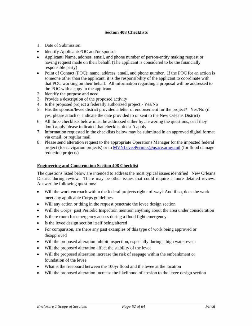
Enclosure 1 Scope of Services Page 62 of 64 Final
Section 408 Checklists
1. Date of Submission: • Identify Applicant/POC and/or sponsor • Applicant: Name, address, email, and phone number of person/entity making request or
having request made on their behalf. (The applicant is considered to be the financially responsible party)
• Point of Contact (POC): name, address, email, and phone number. If the POC for an action is someone other than the applicant, it is the responsibility of the applicant to coordinate with that POC working on their behalf. All information regarding a proposal will be addressed to the POC with a copy to the applicant
2. Identify the purpose and need 3. Provide a description of the proposed activity 4. Is the proposed project a federally authorized project - Yes/No 5. Has the sponsor/levee district provided a letter of endorsement for the project? Yes/No (if
yes, please attach or indicate the date provided to or sent to the New Orleans District) 6. All three checklists below must be addressed either by answering the questions, or if they
don’t apply please indicated that checklist doesn’t apply 7. Information requested in the checklists below may be submitted in an approved digital format
via email, or regular mail 8. Please send alteration request to the appropriate Operations Manager for the impacted federal
project (for navigation projects) or to [email protected] (for flood damage reduction projects)
Engineering and Construction Section 408 Checklist
The questions listed below are intended to address the most typical issues identified New Orleans District during review. There may be other issues that could require a more detailed review. Answer the following questions:
• Will the work encroach within the federal projects rights-of-way? And if so, does the work meet any applicable Corps guidelines
• Will any action or thing in the request penetrate the levee design section • Will the Corps’ past Periodic Inspection mention anything about the area under consideration • Is there room for emergency access during a flood fight emergency • Is the levee design section itself being altered • For comparison, are there any past examples of this type of work being approved or
disapproved • Will the proposed alteration inhibit inspection, especially during a high water event • Will the proposed alteration affect the stability of the levee • Will the proposed alteration increase the risk of seepage within the embankment or
foundation of the levee • What is the freeboard between the 100yr flood and the levee at the location • Will the proposed alteration increase the likelihood of erosion to the levee design section

Enclosure 1 Scope of Services Page 63 of 64 Final
References: The following is a list of references containing evaluation processes, design standards and operation and maintenance procedures that may be relevant to consider for modifications to levees, floodwalls, or channels. Though some of these references may be expired, it is still prudent to use them as a first level of back check. • 33 CFR Part 208, Section 208.10. Local flood protection works, maintenance and operation
of structures and facilities • Engineer Manual (EM) 1110-1-1005, Engineering and Design: Control and Topographic
Surveying, 1 January 2007 • EM 1110-2-1418, Channel Stability Assessment for Flood Control Projects, 31 October 1994 • EM 1110-2-1601, Hydraulic Design of Flood Control Channels, 30 June 1994 • EM 1110-1-1804, Geotechnical Investigations, 1 January 2001 • EM 1110-2-1902, Slope Stability, 31 October 2003 • EM 1110-1-1904, Settlement Analysis, 30 September 1990 • EM 1110-2-1906, Laboratory Soils Testing, 30 November 1970 • EM 1110-2-1913, Design and Construction of Levees, 30 April 2000 • EM 1110-2-1914, Design, Construction, and Maintenance of Relief Wells, 29 May 1992 • EM 1110-2-2502, Retaining and Flood Walls, 29 September 1989 • EM 1110-2-2504, Sheet Pile Walls, 31 March 1994 • EM 1110-2-2902, Conduits, Culverts, and Pipes, 31 March 1998 • Engineer Regulation (ER) 1110-2-1942, Inspection, Monitoring, and Maintenance of Relief
Wells, 29 February 1988 • Engineer Technical Letter (ETL) 1110-2-581, Engineering and Design: Guidelines for
Landscape Planting and Vegetation Management at Levees, Floodwalls, Embankment Dams, and Appurtenant Structures, 10 April 2009
• ETL 1110-2-575, Evaluation of I-walls, 1 September 2011 • EC 1110-2-6066, Design of I-walls, 1 April 2011. EXPIRED • U.S. Department of Interior Bureau of Reclamation and U.S. Army Corps of Engineers. 3
December 2012. Best Practices in Dam and Levee Safety Risk Analysis • ER 1110-1-1807, Drilling in Earth Embankment Dams and Levees
Environmental Section 408 Checklist
The following should be included in a Section 408 Environmental submission.
• Map of project area: This includes the actual project and any staging areas needed for project construction. The map should include the State, County, and when known, Township, Range, and Section. Include any other information to assist in understanding the exact location and type of environmental resources in the project area
• Is the project in or near a wetland • What is the nearest stream, river, or lake near the project • Are you aware of any historic buildings or archeological sites in the
project area? If yes, list these • Project Description: Include a basic and brief (1-2 paragraphs) but clear description of the
proposed activity and a brief statement of why it is needed. If further information is needed the Corps will contact the submitter

Enclosure 1 Scope of Services Page 64 of 64 Final
• Is excavation a part of this project? If so, what are the quantities • Will the staging or transportation of equipment associated with this project
impact native soils • Are there any other permits/approvals required for this project (i.e. Regulatory
10/404 permit, 401 Water quality permit or any other local, state, or Federal permits)
• Schedule: Provide the construction schedule if known. The timing, duration, and nature of
activities can change the types of impacts we are concerned about
• Land Ownership: Clearly state who owns and operates the levee or federally authorized project. Provide a citation for the Project Cooperation Agreement if possible
• Who will the approval be given to • Do you have a record of their initial agreement for the project • Does the Corps have a real estate interest (do we own the property or maintain an
easement)
Real Estate Section 408 Checklist
The Corps’ Real Estate Division requires the information identified below be included in the initial Section 408 request. Real Estate will evaluate the initial request in coordination with other District elements and managing agencies to determine if the proposal is appropriate. Additional information may be requested by Real Estate. • Location of proposed activity. Include Address, County, City, State,
Section/Township/Range, and Tax Lot parcels (if available) • Describe footprint of proposed activity including structures/facilities, dimensions, and
acreage of property being requested affected • Exhibit(s) (site map, survey, drawing, aerial photograph, etc.) depicting proposed location
and other significant features