STATE OF CALIFORNIA FENESTRATION INSTALLATION · STATE OF CALIFORNIA FENESTRATION INSTALLATION ......
292
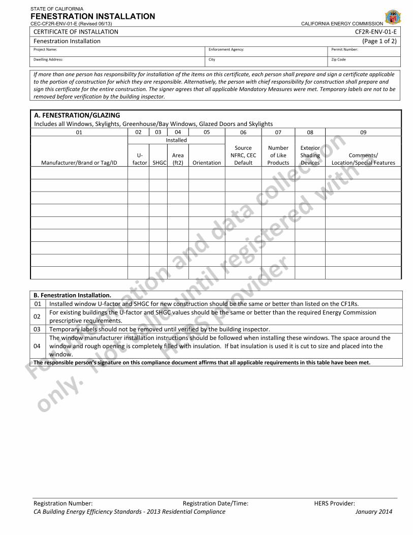
STATE OF CALIFORNIA FENESTRATION INSTALLATION CEC-CF2R-ENV-01-E (Revised 06/13) CALIFORNIA ENERGY COMMISSION CERTIFICATE OF INSTALLATION CF2R‐ENV‐01‐E Fenestration Installation (Page 1 of 2) Project Name: Enforcement Agency: Permit Number: Dwelling Address: City Zip Code Registration Number: Registration Date/Time: HERS Provider: If more than one person has responsibility for installation of the items on this certificate, each person shall prepare and sign a certificate applicable to the portion of construction for which they are responsible. Alternatively, the person with chief responsibility for construction shall prepare and sign this certificate for the entire construction. The signer agrees that all applicable Mandatory Measures were met. Temporary labels are not to be removed before verification by the building inspector. A. FENESTRATION/GLAZING Includes all Windows, Skylights, Greenhouse/Bay Windows, Glazed Doors and Skylights 01 02 03 04 05 06 07 08 09 Manufacturer/Brand or Tag/ID Installed Source NFRC, CEC Default Number of Like Products Exterior Shading Devices Comments/ Location/Special Features U‐ factor SHGC Area (ft2) Orientation B. Fenestration Installation. 01 Installed window U‐factor and SHGC for new construction should be the same or better than listed on the CF1Rs. 02 For existing buildings the U‐factor and SHGC values should be the same or better than the required Energy Commission prescriptive requirements. 03 Temporary labels should not be removed until verified by the building inspector. 04 The window manufacturer installation instructions should be followed when installing these windows. The space around the window and rough opening is completely filled with insulation. If bat insulation is used it is cut to size and placed into the window. The responsible person’s signature on this compliance document affirms that all applicable requirements in this table have been met. CA Building Energy Efficiency Standards ‐ 2013 Residential Compliance January 2014
Transcript of STATE OF CALIFORNIA FENESTRATION INSTALLATION · STATE OF CALIFORNIA FENESTRATION INSTALLATION ......
STATE OF CALIFORNIA
FENESTRATION INSTALLATION CEC-CF2R-ENV-01-E (Revised 06/13) CALIFORNIA ENERGY COMMISSION
CERTIFICATE OF INSTALLATION CF2R‐ENV‐01‐E Fenestration Installation (Page 1 of 2) Project Name: Enforcement Agency: Permit Number:
Dwelling Address: City Zip Code
Registration Number: Registration Date/Time: HERS Provider:
If more than one person has responsibility for installation of the items on this certificate, each person shall prepare and sign a certificate applicable to the portion of construction for which they are responsible. Alternatively, the person with chief responsibility for construction shall prepare and sign this certificate for the entire construction. The signer agrees that all applicable Mandatory Measures were met. Temporary labels are not to be removed before verification by the building inspector.
A. FENESTRATION/GLAZING Includes all Windows, Skylights, Greenhouse/Bay Windows, Glazed Doors and Skylights
01 02 03 04 05 06 07 08 09
Manufacturer/Brand or Tag/ID
Installed Source
NFRC, CEC Default
Number of Like Products
Exterior Shading Devices
Comments/ Location/Special Features
U‐factor SHGC
Area (ft2) Orientation
B. Fenestration Installation. 01 Installed window U‐factor and SHGC for new construction should be the same or better than listed on the CF1Rs.
02 For existing buildings the U‐factor and SHGC values should be the same or better than the required Energy Commission prescriptive requirements.
03 Temporary labels should not be removed until verified by the building inspector.
04 The window manufacturer installation instructions should be followed when installing these windows. The space around the window and rough opening is completely filled with insulation. If bat insulation is used it is cut to size and placed into the window.
The responsible person’s signature on this compliance document affirms that all applicable requirements in this table have been met.
CA Building Energy Efficiency Standards ‐ 2013 Residential Compliance January 2014
STATE OF CALIFORNIA
FENESTRATION INSTALLATION CEC-CF2R-ENV-01-E (Revised 06/13) CALIFORNIA ENERGY COMMISSION
CERTIFICATE OF INSTALLATION CF2R‐ENV‐01‐E Fenestration Installation (Page 2 of 2) Project Name: Enforcement Agency: Permit Number:
Dwelling Address: City Zip Code
Registration Number: Registration Date/Time: HERS Provider: CA Building Energy Efficiency Standards ‐ 2013 Residential Compliance January 2014
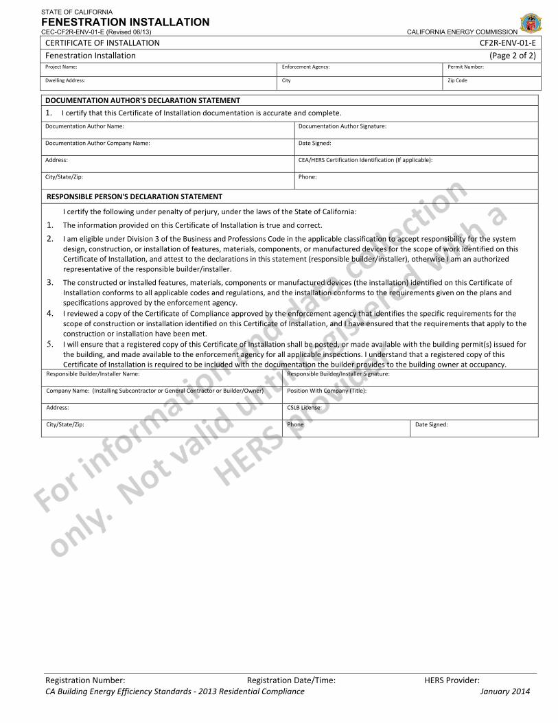
DOCUMENTATION AUTHOR'S DECLARATION STATEMENT
1. I certify that this Certificate of Installation documentation is accurate and complete.
Documentation Author Name: Documentation Author Signature:
Documentation Author Company Name: Date Signed:
Address: CEA/HERS Certification Identification (If applicable):
City/State/Zip: Phone:
RESPONSIBLE PERSON'S DECLARATION STATEMENT
I certify the following under penalty of perjury, under the laws of the State of California:
1. The information provided on this Certificate of Installation is true and correct.
2. I am eligible under Division 3 of the Business and Professions Code in the applicable classification to accept responsibility for the system design, construction, or installation of features, materials, components, or manufactured devices for the scope of work identified on this Certificate of Installation, and attest to the declarations in this statement (responsible builder/installer), otherwise I am an authorized representative of the responsible builder/installer.
3. The constructed or installed features, materials, components or manufactured devices (the installation) identified on this Certificate of Installation conforms to all applicable codes and regulations, and the installation conforms to the requirements given on the plans and specifications approved by the enforcement agency.
4. I reviewed a copy of the Certificate of Compliance approved by the enforcement agency that identifies the specific requirements for the scope of construction or installation identified on this Certificate of Installation, and I have ensured that the requirements that apply to the construction or installation have been met.
5. I will ensure that a registered copy of this Certificate of Installation shall be posted, or made available with the building permit(s) issued for the building, and made available to the enforcement agency for all applicable inspections. I understand that a registered copy of this Certificate of Installation is required to be included with the documentation the builder provides to the building owner at occupancy.
Responsible Builder/Installer Name: Responsible Builder/Installer Signature:
Company Name: (Installing Subcontractor or General Contractor or Builder/Owner) Position With Company (Title):
Address: CSLB License:
City/State/Zip: Phone Date Signed:
CERTIFICATE OF INSTALLATION ‐ USER INSTRUCTIONS CF2R‐ENV‐01‐E Fenestration Installation (Page 1 of 1)
CA Building Energy Efficiency Standards ‐ 2013 Residential Compliance January 2014
Before installation of fenestration the installer shall verify the fenestration product matches either the CF1R‐ NCB, or CF1R‐ADD, or CF1R‐ALT or CF1R‐PRF Certificate form. If the efficiencies are worse (less efficient) then windows cannot be installed until proof with an updated certificate form or computer energy compliance run documenting the less efficient windows. If the installed fenestration is better (more efficient) that the documentation then no further proof of documentation is required and installation is allowed. A. FENESTRATION/GLAZING 1. Manufacturer/Brand or Tag/ID: Provide the manufacturer and Brand in which identifies the fenestration product being
installed. Or if using Tag or ID designator ensure each unique type is used consistently throughout the plan set (elevations, finish schedules, etc.) such as, Window‐1, Skylight‐1 and etc…to identify each surface. It should also be consistently used on the other forms in the same compliance documentation.
Installed: 2. U‐factor: Indicate the specified U‐factor that is being installed of the same liked fenestration product. Do not mix different
types on the same line. 3. SHGC: Indicate the specified SHGC that is being installed of the same liked fenestration product. Do not mix different types
on the same line. 4. Surface Area: Indicate the total surface area ft² of all of the fenestration with the same like characteristics. Do not mix
different fenestration area on the same line. 5. Orientation: Indicate the orientation of the same like fenestration. If the orientation varies of the same liked fenestration
then enter multiple orientation on the same line. Enter S, N, E, or W. 6. Source: NFRC or CEC Default Values. Enter the appropriate temporary label certificate identified as either NFRC or CEC
Default. All windows installed must have a label certificate in which identifies the window’s efficiencies. NFRC Rated products have a temporarily label on the product that can be looked up in the NFRC product directory (http://search.nfrc.org/search/searchDefault.aspx).
7. Number of Like Products: Enter the number of the same liked fenestration being installed. Use as many lines as necessary. 8. Exterior Shading Devices: If exterior shading devices are installed in conjunction with fenestration then select the type of
shading device (sunscreens, louvered, vertical roller or shades or retractable awnings or roll down or slats) or if an overhang is already or going to be installed.
9. Comments/Location/Special Features: Locations – Special Features to provide additional information for the field inspector.

CERTIFICATE OF INSTALLATION ‐ DATA FIELD DEFINITIONS AND CALCULATIONS CF2R‐ENV‐01‐E Fenestration Installation (Page 1 of 1)
CA Building Energy Efficiency Standards ‐ 2013 Residential Compliance January 2014
DOCUMENTATION AUTHOR'S DECLARATION STATEMENT
1. I certify that this Certificate of Installation documentation is accurate and complete.
Documentation Author Name: Documentation Author Signature:
Documentation Author Company Name: Date Signed:
Address: CEA/HERS Certification Identification (If applicable):
City/State/Zip: Phone:
RESPONSIBLE PERSON'S DECLARATION STATEMENT
I certify the following under penalty of perjury, under the laws of the State of California:
1. The information provided on this Certificate of Installation is true and correct.
2. I am eligible under Division 3 of the Business and Professions Code in the applicable classification to accept responsibility for the system design, construction, or installation of features, materials, components, or manufactured devices for the scope of work identified on this Certificate of Installation, and attest to the declarations in this statement (responsible builder/installer), otherwise I am an authorized representative of the responsible builder/installer.
3. The constructed or installed features, materials, components or manufactured devices (the installation) identified on this Certificate of Installation conforms to all applicable codes and regulations, and the installation conforms to the requirements given on the plans and specifications approved by the enforcement agency.
4. I reviewed a copy of the Certificate of Compliance approved by the enforcement agency that identifies the specific requirements for the scope of construction or installation identified on this Certificate of Installation, and I have ensured that the requirements that apply to the construction or installation have been met.
5. I will ensure that a registered copy of this Certificate of Installation shall be posted, or made available with the building permit(s) issued for the building, and made available to the enforcement agency for all applicable inspections. I understand that a registered copy of this Certificate of Installation is required to be included with the documentation the builder provides to the building owner at occupancy.
Responsible Builder/Installer Name: Responsible Builder/Installer Signature:
Company Name: (Installing Subcontractor or General Contractor or Builder/Owner) Position With Company (Title):
Address: CSLB License:
City/State/Zip: Phone Date Signed:
STATE OF CALIFORNIA
ENVELOPE AIR SEALING CEC-CF2R-ENV-02-E (Revised 06/13) CALIFORNIA ENERGY COMMISSION
CERTIFICATE OF INSTALLATION CF2R‐ENV‐02‐E Envelope Air Sealing ‐ ENV‐02 (Page 1 of 4) Project Name: Enforcement Agency: Permit Number:
Dwelling Address: City Zip Code
CA Building Energy Efficiency Standards ‐ 2013 Residential Compliance January 2014
Note: The Energy Efficiency Standards Section 110.7 requires that “all joints, penetrations and other openings in the building envelope that are potential sources of air leakage shall be caulked, gasketed, weather stripped, or otherwise sealed to limit infiltration and exfiltration.” The requirements below are for newly constructed spaces, additions and alterations to existing assemblies. In areas where Spray Foam (SPF) insulation is used, the SPF can be considered the air barrier. Rigid board insulation is also an air barrier as long as infiltration cannot bypass the product. All other forms of insulation are not considered an air barrier and cannot be used as such.
A. Does the scope of this project include (select Yes or No to the following options):01 Raised Floor Air Sealing Y or N 02 Wall Air Sealing Y or N 03 Ceiling Air Sealing Y or N 04 Conditioned Space Above or Adjacent to Garage Air Sealing Y or N 05 Cantilevered Floor Air Sealing Y or N 06 Attached porch Roof Air Sealing Y or N 07 Multifamily Air Sealing Y or N B. RAISED FLOOR AIR SEALING 01 All gaps in the raised floor are sealed. 02 All chases sealed at floor level using a hard cover and the hard cover is sealed.03 All Plumbing and electrical wires that penetrate the floor are sealed.04 Subfloor sheathing is glued or sealed at all exterior panel edges, to create a continuous air tight subfloor The responsible person’s signature on this compliance document affirms that all applicable requirements in this table have been met.
C. WALL AIR SEALING
01 All penetrations through the exterior wall are sealed to provide an air‐tight envelope to unconditioned spaces such as theoutdoors, attic, garage and crawl space.
02 Exterior wall air barrier is sealed at the top plate and bottom plate in each stud bay.03 All electrical boxes including knockouts that penetrate the exterior sheathing to unconditioned space are sealed.04 All openings in the top and bottom plate, including all interior and exterior walls, to unconditioned space are sealed.05 Exterior bottom plates (all stories) are sealed to the floor using the appropriate method under the entire exterior bottom
plate of the home. 06 All gaps around windows and doors are sealed. Sealant used was specified by window manufacturer. 07 Rim Joist gaps/openings are fully sealed. 08 Fan exhaust ducts that run between conditioned floors to the exterior walls include a damper at the exterior wall.09 Metal tie downs are insulated between exterior framing and tie down.10 HVAC boots installed in the walls are sealed to the surrounding drywall.The responsible person’s signature on this compliance document affirms that all applicable requirements in this table have been met. D. CEILING AIR SEALING
01 There is a continuous air barrier at the ceiling level. All openings in the ceiling such as into walls, drops, chasses, double walls are sealed.
02 Chimneys and flues have sheet metal flashings. The flashings are sealed to the chimney/flue with fire rated caulk and sealed to surrounding framing.
03 All penetrations through the top plate of interior and exterior walls are sealed.
04 Electrical boxes, fire alarm boxes, fire sprinklers, cut into ceiling are sealed to the surrounding drywall and all gaps in the box are sealed. If not possible to seal fixture directly a secondary barrier was created around the fixture that creates an air tight seal between conditioned and unconditioned spaces.
05 All installed recessed light fixtures that penetrate the ceiling to unconditioned space are rated to be Insulation Contact and air tight (IC and AT) which allows direct contact with insulation. Housing is sealed to the drywall.
06 Exhaust fan housings are sealed to surrounding drywall and all holes and seams in housing sealed. 07 All chases are covered with a hard cover that is sealed to framing.
STATE OF CALIFORNIA
ENVELOPE AIR SEALING CEC-CF2R-ENV-02-E (Revised 06/13) CALIFORNIA ENERGY COMMISSION
CERTIFICATE OF INSTALLATION CF2R‐ENV‐02‐E Envelope Air Sealing ‐ ENV‐02 (Page 2 of 4) Project Name: Enforcement Agency: Permit Number:
Dwelling Address: City Zip Code
CA Building Energy Efficiency Standards ‐ 2013 Residential Compliance January 2014
08 Double walls that open to attic are covered and cover is sealed to framing.09 Attic access forms airtight seal from conditioned space to unconditioned space. Vertical attic access have mechanical
compression using screws or latches. 10 Knee walls are air tight:
(a) Knee walls have solid blocking at the ceiling level to control air leakage down the wall. Ensure blocking is sealed to framing and drywall.
(b) When the knee wall is placed on top of a subfloor the open cavity below the subfloor and the ceiling below are sealed.
11 Soffits are air tight. Either: a hard cover at ceiling level that seals the top plate, or interior of the soffit is air tight. If an interior wall is part of the soffit additional blocking must be added in the wall at the bottom of the soffit.
12 HVAC ducts in a chase are sealed at the ceiling level. Insulation not considered as air barrier (batts) not allowed.13 HVAC boots that penetrate the ceiling are sealed to the surrounding drywall.The responsible person’s signature on this compliance document affirms that all applicable requirements in this table have been met E. CONDITIONED SPACE ABOVE OR ADJACENT TO GARAGE AIR SEALING01 All penetration in the subfloor above the garage into conditioned space are installed to meet the raised floor air sealing
requirements above. 02 Air infiltration does not enter the house between the space above the garage and subfloor. Select the option used below:03
[Y or No]
(a) Edges are sealed at the garage ceiling (typical drywall) at the perimeter of the garage to create a continuous air tight surface between the garage and adjacent conditioned envelope. Sealed all plumbing, electric and mechanical penetrations between the garage and the adjacent conditioned space. For an open‐web truss, airtight blocking is added on four sides of the garage perimeter. Insulation can be placed on the garage ceiling.
04
[Y or No]
(b) Sealed band joist above the wall at the garage to conditioned space transition. Sealed all subfloor seams and penetrations between the conditioned space and the garage. Insulation is placed in contact with subfloor below conditioned space.
The responsible person’s signature on this compliance document affirms that all applicable requirements in this table have been met. F. CANTILEVERED FLOOR AIR SEALING 01 Airtight blocking is installed between joists where the wall rim joist would have been located in the absence of a cantilever.02 Exterior sheathing is installed to the bottom of the cantilever so that there is a continuous air and weather barrier for the
cantilever. The cantilevered joist must be insulated to the same R‐value as would be required for the subfloor prior to closing. 03 Any gaps, cracks or penetrations in the air barrier of the cantilever are sealed. Can lights in the cantilever must be IC and AT
rated and properly sealed to sheathing. The responsible person’s signature on this compliance document affirms that all applicable requirements in this table have been met. G. ATTACHED PORCH/ATTIC AIR SEALING 01 Exterior wall, air sealant is placed at the intersection of the porch and exterior wall. 02 Truss framing blocking is used at top and bottom of each wall/roof section.The responsible person’s signature on this compliance document affirms that all applicable requirements in this table have been met.
H. MULTIFAMILY AIR SEALING 01 Multifamily buildings must meet all air sealing requirements listed above.02 Each dwelling unit must be air sealed to stop air movement from one unit to another. 03 Floor AND Ceiling of each Dwelling Unit: All penetrations through the floor and ceiling of each unit are sealed including,
electric and gas utilities, water pipes, drain pipes, fire protection service pipes, communication wiring. 04 Elevator penthouse, mechanical penthouse, stairwell doors, roof access hatch, plumbing stacks sealed to reduce air transfer
from attached spaces. 05 Common Walls: Bottom plate between units is sealed to the subfloor. All penetrations in the common walls are sealed
including electrical boxes, wiring and plumbing penetrations. Perpendicular Interior walls that open into the common walls are sealed.
STATE OF CALIFORNIA
ENVELOPE AIR SEALING CEC-CF2R-ENV-02-E (Revised 06/13) CALIFORNIA ENERGY COMMISSION
CERTIFICATE OF INSTALLATION CF2R‐ENV‐02‐E Envelope Air Sealing ‐ ENV‐02 (Page 3 of 4) Project Name: Enforcement Agency: Permit Number:
Dwelling Address: City Zip Code
CA Building Energy Efficiency Standards ‐ 2013 Residential Compliance January 2014
06 Vertical Chases for garbage chutes, elevator shafts, and HVAC ducting plumbing must be sealed to the floor and ceiling of each unit to stop air movement up and around the chase due to stack effect.
07 Vertical Chases for garbage chutes, elevator shafts, and HVAC ducting plumbing, wiring etc. must be sealed to stop air movement through the chase to the surrounding spaces.
08 Common Hallways must be sealed to stop air movement into dwelling units. The responsible person’s signature on this compliance document affirms that all applicable requirements in this table have been met.
STATE OF CALIFORNIA
ENVELOPE AIR SEALING CEC-CF2R-ENV-02-E (Revised 06/13) CALIFORNIA ENERGY COMMISSION
CERTIFICATE OF INSTALLATION CF2R‐ENV‐02‐E Envelope Air Sealing ‐ ENV‐02 (Page 4 of 4) Project Name: Enforcement Agency: Permit Number:
Dwelling Address: City Zip Code
CA Building Energy Efficiency Standards ‐ 2013 Residential Compliance January 2014
DOCUMENTATION AUTHOR'S DECLARATION STATEMENT
1. I certify that this Certificate of Installation documentation is accurate and complete.
Documentation Author Name: Documentation Author Signature:
Documentation Author Company Name: Date Signed:
Address: CEA/HERS Certification Identification (If applicable):
City/State/Zip: Phone:
RESPONSIBLE PERSON'S DECLARATION STATEMENT
I certify the following under penalty of perjury, under the laws of the State of California:
1. The information provided on this Certificate of Installation is true and correct.
2. I am eligible under Division 3 of the Business and Professions Code in the applicable classification to accept responsibility for the system design, construction, or installation of features, materials, components, or manufactured devices for the scope of work identified on this Certificate of Installation, and attest to the declarations in this statement (responsible builder/installer), otherwise I am an authorized representative of the responsible builder/installer.
3. The constructed or installed features, materials, components or manufactured devices (the installation) identified on this Certificate of Installation conforms to all applicable codes and regulations, and the installation conforms to the requirements given on the plans and specifications approved by the enforcement agency.
4. I reviewed a copy of the Certificate of Compliance approved by the enforcement agency that identifies the specific requirements for the scope of construction or installation identified on this Certificate of Installation, and I have ensured that the requirements that apply to the construction or installation have been met.
5. I will ensure that a registered copy of this Certificate of Installation shall be posted, or made available with the building permit(s) issued for the building, and made available to the enforcement agency for all applicable inspections. I understand that a registered copy of this Certificate of Installation is required to be included with the documentation the builder provides to the building owner at occupancy.
Responsible Builder/Installer Name: Responsible Builder/Installer Signature:
Company Name: (Installing Subcontractor or General Contractor or Builder/Owner) Position With Company (Title):
Address: CSLB License:
City/State/Zip: Phone Date Signed:
STATE OF CALIFORNIA
INSULATION INSTALLATION CEC-CF2R-ENV-03-E (Revised 06/13) CALIFORNIA ENERGY COMMISSION
CERTIFICATE OF INSTALLATION CF2R‐ENV‐03‐E Insulation Installation (Page 1 of 4) Project Name: Enforcement Agency: Permit Number:
Dwelling Address: City Zip Code
CA Building Energy Efficiency Standards ‐ 2013 Residential Compliance January 2014
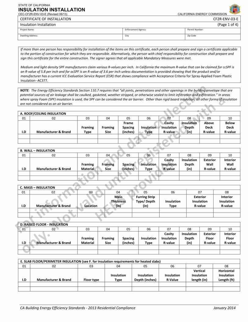
If more than one person has responsibility for installation of the items on this certificate, each person shall prepare and sign a certificate applicable to the portion of construction for which they are responsible. Alternatively, the person with chief responsibility for construction shall prepare and sign this certificate for the entire construction. The signer agrees that all applicable Mandatory Measures were met. Medium and light density SPF manufacturers claim various R‐values per inch. In California the maximum R‐value that can be claimed for ccSPF is an R‐value of 5.8 per inch and for ocSPF is an R‐value of 3.6 per inch unless documentation is provided showing that the product and/or manufacturer has a current ICC Evaluation Service Report (ESR) that shows compliance with Acceptance Criteria for Spray‐Applied Foam Plastic Insulation‐‐AC377. NOTE: The Energy Efficiency Standards Section 110.7 requires that “all joints, penetrations and other openings in the building envelope that are potential sources of air leakage shall be caulked, gasketed, weather stripped, or otherwise sealed to limit infiltration and exfiltration.” In areas where spray Foam (SPF) insulation is used, the SPF can be considered the air barrier. Other than rigid board insulation, all other forms of insulation are not considered as an air barrier. A. ROOF/CEILING INSULATION 01 02 03 04 05 06 07 08 09 10
I.D Manufacturer & Brand Framing Type
Framing Size
Frame Spacing (inches)
Insulation Type
Cavity Insulation R‐value
Insulation Depth (in)
Above Deck
R‐value
Below Deck
R‐value
B. WALL – INSULATION 01 02 03 04 05 06 07 08 09 10
I.D Manufacturer & Brand Framing Material
Framing Size
Spacing (inches)
Insulation Type
Cavity Insulation R‐value
Insulation Depth (in)
Exterior Wall
R‐value
Interior Wall
R‐value
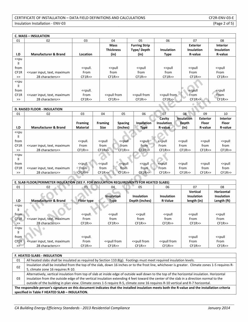
C. MASS – INSULATION 01 02 03 04 05 06 07 08
I.D Manufacturer & Brand Location
Mass Thickness
(in)
Furring Strip Type/ Depth
(in) Insulation
Type
Exterior Insulation R‐value
Interior Insulation R‐value
D. RAISED FLOOR ‐ INSULATION 01 02 03 04 05 06 07 08 09 10
I.D Manufacturer & Brand Framing Material
Framing Size
Spacing (inches)
Insulation Type
Cavity Insulation R‐value
Insulation Depth (in)
Exterior Floor R‐value
Interior Floor R‐value
E. SLAB FLOOR/PERIMETER INSULATION (see F. for insulation requirements for heated slabs) 01 02 03 04 05 06 07 08
I.D Manufacturer & Brand Floor type Insulation
Type Insulation
Depth (inches) Insulation R‐Value
Vertical Insulation length (in)
Horizontal Insulation Length (ft)
STATE OF CALIFORNIA
INSULATION INSTALLATION CEC-CF2R-ENV-03-E (Revised 06/13) CALIFORNIA ENERGY COMMISSION
CERTIFICATE OF INSTALLATION CF2R‐ENV‐03‐E Insulation Installation (Page 2 of 4) Project Name: Enforcement Agency: Permit Number:
Dwelling Address: City Zip Code
CA Building Energy Efficiency Standards ‐ 2013 Residential Compliance January 2014
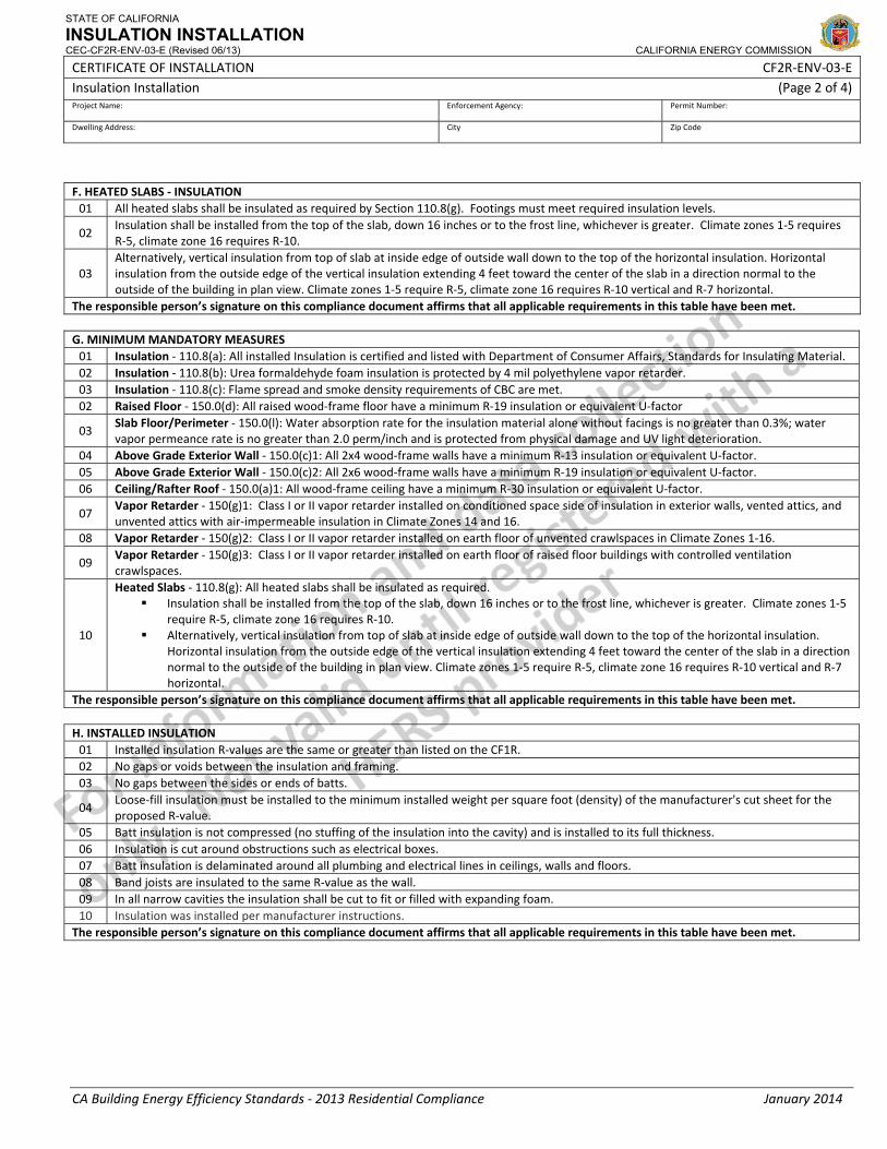
F. HEATED SLABS ‐ INSULATION 01 All heated slabs shall be insulated as required by Section 110.8(g). Footings must meet required insulation levels.
02 Insulation shall be installed from the top of the slab, down 16 inches or to the frost line, whichever is greater. Climate zones 1‐5 requires R‐5, climate zone 16 requires R‐10.
03 Alternatively, vertical insulation from top of slab at inside edge of outside wall down to the top of the horizontal insulation. Horizontal insulation from the outside edge of the vertical insulation extending 4 feet toward the center of the slab in a direction normal to the outside of the building in plan view. Climate zones 1‐5 require R‐5, climate zone 16 requires R‐10 vertical and R‐7 horizontal.
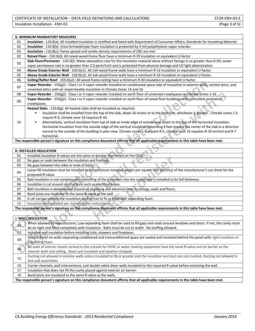
The responsible person’s signature on this compliance document affirms that all applicable requirements in this table have been met. G. MINIMUM MANDATORY MEASURES 01 Insulation ‐ 110.8(a): All installed Insulation is certified and listed with Department of Consumer Affairs, Standards for Insulating Material. 02 Insulation ‐ 110.8(b): Urea formaldehyde foam insulation is protected by 4 mil polyethylene vapor retarder. 03 Insulation ‐ 110.8(c): Flame spread and smoke density requirements of CBC are met. 02 Raised Floor ‐ 150.0(d): All raised wood‐frame floor have a minimum R‐19 insulation or equivalent U‐factor
03 Slab Floor/Perimeter ‐ 150.0(l): Water absorption rate for the insulation material alone without facings is no greater than 0.3%; water vapor permeance rate is no greater than 2.0 perm/inch and is protected from physical damage and UV light deterioration.
04 Above Grade Exterior Wall ‐ 150.0(c)1: All 2x4 wood‐frame walls have a minimum R‐13 insulation or equivalent U‐factor. 05 Above Grade Exterior Wall ‐ 150.0(c)2: All 2x6 wood‐frame walls have a minimum R‐19 insulation or equivalent U‐factor. 06 Ceiling/Rafter Roof ‐ 150.0(a)1: All wood‐frame ceiling have a minimum R‐30 insulation or equivalent U‐factor.
07 Vapor Retarder ‐ 150(g)1: Class I or II vapor retarder installed on conditioned space side of insulation in exterior walls, vented attics, and unvented attics with air‐impermeable insulation in Climate Zones 14 and 16.
08 Vapor Retarder ‐ 150(g)2: Class I or II vapor retarder installed on earth floor of unvented crawlspaces in Climate Zones 1‐16.
09 Vapor Retarder ‐ 150(g)3: Class I or II vapor retarder installed on earth floor of raised floor buildings with controlled ventilation crawlspaces.
10
Heated Slabs ‐ 110.8(g): All heated slabs shall be insulated as required. Insulation shall be installed from the top of the slab, down 16 inches or to the frost line, whichever is greater. Climate zones 1‐5
require R‐5, climate zone 16 requires R‐10. Alternatively, vertical insulation from top of slab at inside edge of outside wall down to the top of the horizontal insulation.
Horizontal insulation from the outside edge of the vertical insulation extending 4 feet toward the center of the slab in a direction normal to the outside of the building in plan view. Climate zones 1‐5 require R‐5, climate zone 16 requires R‐10 vertical and R‐7 horizontal.
The responsible person’s signature on this compliance document affirms that all applicable requirements in this table have been met. H. INSTALLED INSULATION 01 Installed insulation R‐values are the same or greater than listed on the CF1R. 02 No gaps or voids between the insulation and framing. 03 No gaps between the sides or ends of batts.
04 Loose‐fill insulation must be installed to the minimum installed weight per square foot (density) of the manufacturer's cut sheet for the proposed R‐value.
05 Batt insulation is not compressed (no stuffing of the insulation into the cavity) and is installed to its full thickness. 06 Insulation is cut around obstructions such as electrical boxes. 07 Batt insulation is delaminated around all plumbing and electrical lines in ceilings, walls and floors. 08 Band joists are insulated to the same R‐value as the wall. 09 In all narrow cavities the insulation shall be cut to fit or filled with expanding foam. 10 Insulation was installed per manufacturer instructions.
The responsible person’s signature on this compliance document affirms that all applicable requirements in this table have been met.
STATE OF CALIFORNIA
INSULATION INSTALLATION CEC-CF2R-ENV-03-E (Revised 06/13) CALIFORNIA ENERGY COMMISSION
CERTIFICATE OF INSTALLATION CF2R‐ENV‐03‐E Insulation Installation (Page 3 of 4) Project Name: Enforcement Agency: Permit Number:
Dwelling Address: City Zip Code
CA Building Energy Efficiency Standards ‐ 2013 Residential Compliance January 2014
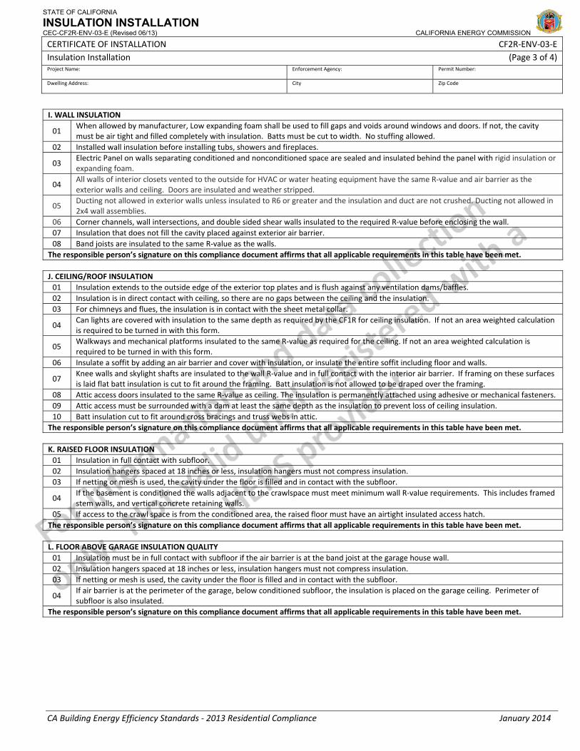
I. WALL INSULATION
01 When allowed by manufacturer, Low expanding foam shall be used to fill gaps and voids around windows and doors. If not, the cavity must be air tight and filled completely with insulation. Batts must be cut to width. No stuffing allowed.
02 Installed wall insulation before installing tubs, showers and fireplaces.
03 Electric Panel on walls separating conditioned and nonconditioned space are sealed and insulated behind the panel with rigid insulation or expanding foam.
04 All walls of interior closets vented to the outside for HVAC or water heating equipment have the same R‐value and air barrier as the exterior walls and ceiling. Doors are insulated and weather stripped.
05 Ducting not allowed in exterior walls unless insulated to R6 or greater and the insulation and duct are not crushed. Ducting not allowed in 2x4 wall assemblies.
06 Corner channels, wall intersections, and double sided shear walls insulated to the required R‐value before enclosing the wall. 07 Insulation that does not fill the cavity placed against exterior air barrier. 08 Band joists are insulated to the same R‐value as the walls.
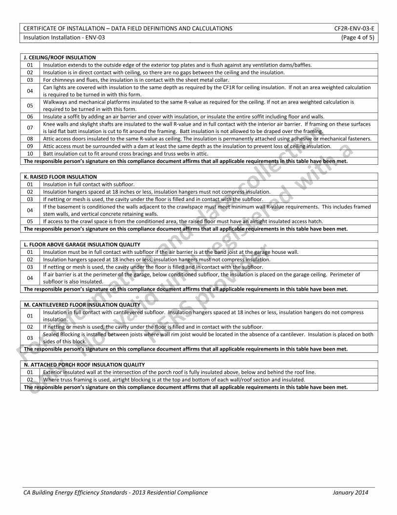
The responsible person’s signature on this compliance document affirms that all applicable requirements in this table have been met. J. CEILING/ROOF INSULATION 01 Insulation extends to the outside edge of the exterior top plates and is flush against any ventilation dams/baffles. 02 Insulation is in direct contact with ceiling, so there are no gaps between the ceiling and the insulation. 03 For chimneys and flues, the insulation is in contact with the sheet metal collar.
04 Can lights are covered with insulation to the same depth as required by the CF1R for ceiling insulation. If not an area weighted calculation is required to be turned in with this form.
05 Walkways and mechanical platforms insulated to the same R‐value as required for the ceiling. If not an area weighted calculation is required to be turned in with this form.
06 Insulate a soffit by adding an air barrier and cover with insulation, or insulate the entire soffit including floor and walls.
07 Knee walls and skylight shafts are insulated to the wall R‐value and in full contact with the interior air barrier. If framing on these surfaces is laid flat batt insulation is cut to fit around the framing. Batt insulation is not allowed to be draped over the framing.
08 Attic access doors insulated to the same R‐value as ceiling. The insulation is permanently attached using adhesive or mechanical fasteners. 09 Attic access must be surrounded with a dam at least the same depth as the insulation to prevent loss of ceiling insulation. 10 Batt insulation cut to fit around cross bracings and truss webs in attic.
The responsible person’s signature on this compliance document affirms that all applicable requirements in this table have been met. K. RAISED FLOOR INSULATION 01 Insulation in full contact with subfloor. 02 Insulation hangers spaced at 18 inches or less, insulation hangers must not compress insulation. 03 If netting or mesh is used, the cavity under the floor is filled and in contact with the subfloor.
04 If the basement is conditioned the walls adjacent to the crawlspace must meet minimum wall R‐value requirements. This includes framed stem walls, and vertical concrete retaining walls.
05 If access to the crawl space is from the conditioned area, the raised floor must have an airtight insulated access hatch. The responsible person’s signature on this compliance document affirms that all applicable requirements in this table have been met. L. FLOOR ABOVE GARAGE INSULATION QUALITY 01 Insulation must be in full contact with subfloor if the air barrier is at the band joist at the garage house wall. 02 Insulation hangers spaced at 18 inches or less, insulation hangers must not compress insulation. 03 If netting or mesh is used, the cavity under the floor is filled and in contact with the subfloor.
04 If air barrier is at the perimeter of the garage, below conditioned subfloor, the insulation is placed on the garage ceiling. Perimeter of subfloor is also insulated.
The responsible person’s signature on this compliance document affirms that all applicable requirements in this table have been met.
STATE OF CALIFORNIA
INSULATION INSTALLATION CEC-CF2R-ENV-03-E (Revised 06/13) CALIFORNIA ENERGY COMMISSION
CERTIFICATE OF INSTALLATION CF2R‐ENV‐03‐E Insulation Installation (Page 4 of 4) Project Name: Enforcement Agency: Permit Number:
Dwelling Address: City Zip Code
CA Building Energy Efficiency Standards ‐ 2013 Residential Compliance January 2014
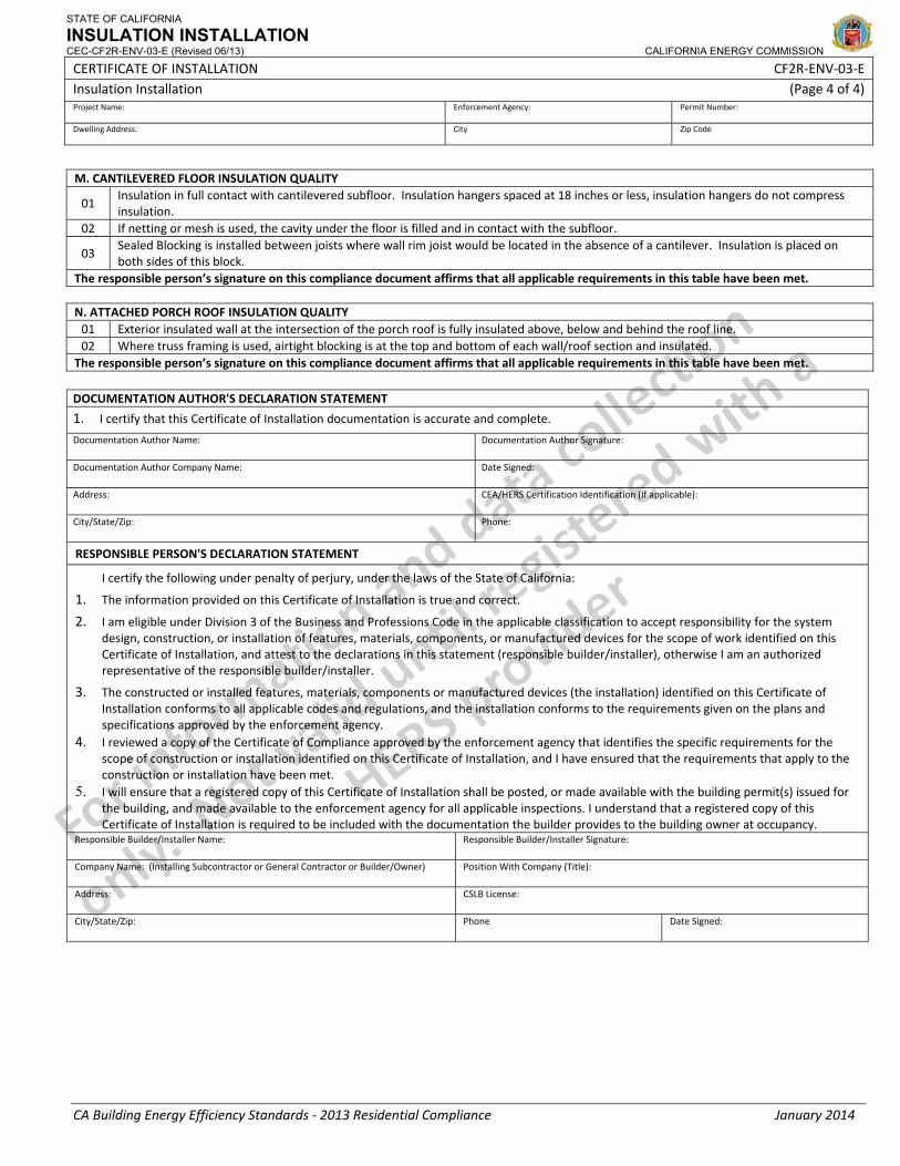
M. CANTILEVERED FLOOR INSULATION QUALITY
01 Insulation in full contact with cantilevered subfloor. Insulation hangers spaced at 18 inches or less, insulation hangers do not compress insulation.
02 If netting or mesh is used, the cavity under the floor is filled and in contact with the subfloor.
03 Sealed Blocking is installed between joists where wall rim joist would be located in the absence of a cantilever. Insulation is placed on both sides of this block.
The responsible person’s signature on this compliance document affirms that all applicable requirements in this table have been met. N. ATTACHED PORCH ROOF INSULATION QUALITY 01 Exterior insulated wall at the intersection of the porch roof is fully insulated above, below and behind the roof line. 02 Where truss framing is used, airtight blocking is at the top and bottom of each wall/roof section and insulated.
The responsible person’s signature on this compliance document affirms that all applicable requirements in this table have been met. DOCUMENTATION AUTHOR'S DECLARATION STATEMENT
1. I certify that this Certificate of Installation documentation is accurate and complete.
Documentation Author Name: Documentation Author Signature:
Documentation Author Company Name: Date Signed:
Address: CEA/HERS Certification Identification (If applicable):
City/State/Zip: Phone:
RESPONSIBLE PERSON'S DECLARATION STATEMENT
I certify the following under penalty of perjury, under the laws of the State of California:
1. The information provided on this Certificate of Installation is true and correct.
2. I am eligible under Division 3 of the Business and Professions Code in the applicable classification to accept responsibility for the system design, construction, or installation of features, materials, components, or manufactured devices for the scope of work identified on this Certificate of Installation, and attest to the declarations in this statement (responsible builder/installer), otherwise I am an authorized representative of the responsible builder/installer.
3. The constructed or installed features, materials, components or manufactured devices (the installation) identified on this Certificate of Installation conforms to all applicable codes and regulations, and the installation conforms to the requirements given on the plans and specifications approved by the enforcement agency.
4. I reviewed a copy of the Certificate of Compliance approved by the enforcement agency that identifies the specific requirements for the scope of construction or installation identified on this Certificate of Installation, and I have ensured that the requirements that apply to the construction or installation have been met.
5. I will ensure that a registered copy of this Certificate of Installation shall be posted, or made available with the building permit(s) issued for the building, and made available to the enforcement agency for all applicable inspections. I understand that a registered copy of this Certificate of Installation is required to be included with the documentation the builder provides to the building owner at occupancy.
Responsible Builder/Installer Name: Responsible Builder/Installer Signature:
Company Name: (Installing Subcontractor or General Contractor or Builder/Owner) Position With Company (Title):
Address: CSLB License:
City/State/Zip: Phone Date Signed:
CERTIFICATE OF INSTALLATION – USER INSTRUCTIONS CF2R‐ENV‐03‐E Insulation Installation ‐ ENV‐03 (Page 1 of 2)
CA Building Energy Efficiency Standards ‐ 2013 Residential Compliance January 2014
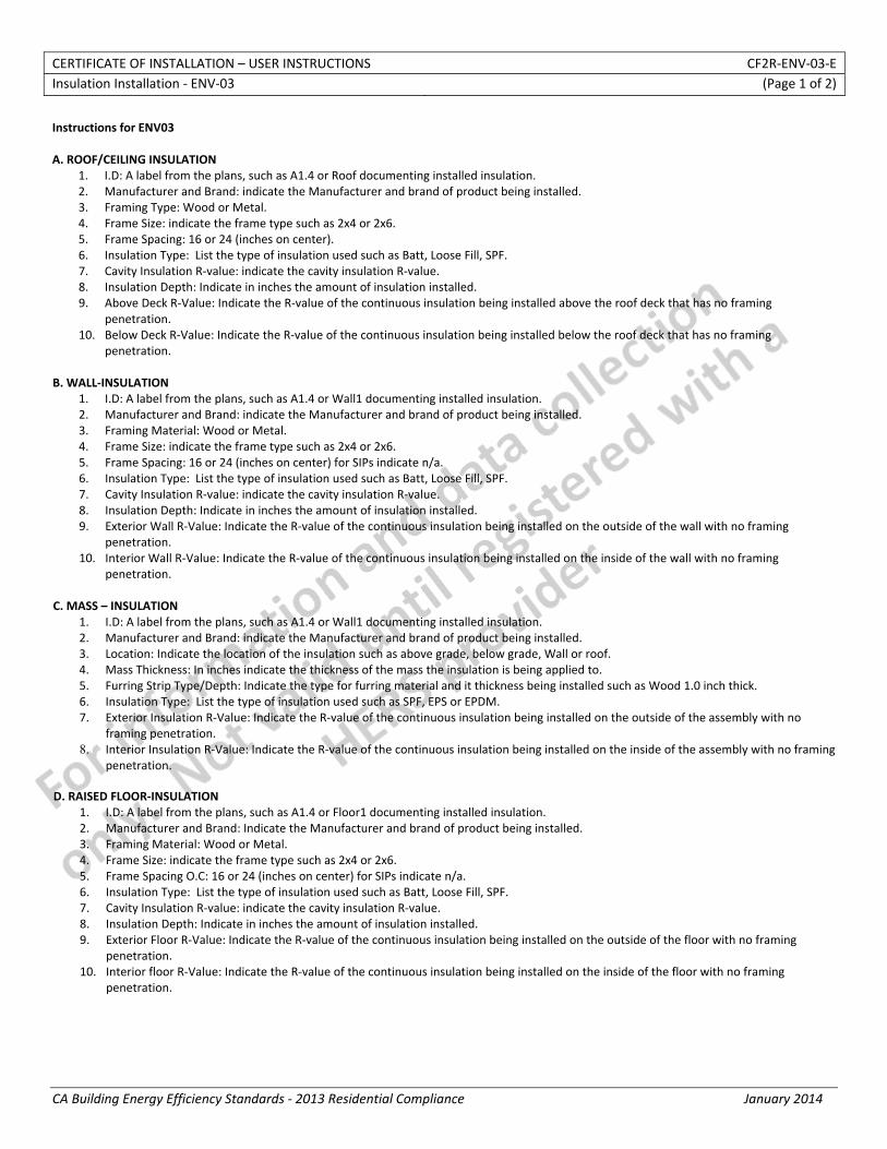
Instructions for ENV03 A. ROOF/CEILING INSULATION
1. I.D: A label from the plans, such as A1.4 or Roof documenting installed insulation. 2. Manufacturer and Brand: indicate the Manufacturer and brand of product being installed. 3. Framing Type: Wood or Metal. 4. Frame Size: indicate the frame type such as 2x4 or 2x6. 5. Frame Spacing: 16 or 24 (inches on center). 6. Insulation Type: List the type of insulation used such as Batt, Loose Fill, SPF. 7. Cavity Insulation R‐value: indicate the cavity insulation R‐value. 8. Insulation Depth: Indicate in inches the amount of insulation installed. 9. Above Deck R‐Value: Indicate the R‐value of the continuous insulation being installed above the roof deck that has no framing
penetration. 10. Below Deck R‐Value: Indicate the R‐value of the continuous insulation being installed below the roof deck that has no framing
penetration. B. WALL‐INSULATION
1. I.D: A label from the plans, such as A1.4 or Wall1 documenting installed insulation. 2. Manufacturer and Brand: indicate the Manufacturer and brand of product being installed. 3. Framing Material: Wood or Metal. 4. Frame Size: indicate the frame type such as 2x4 or 2x6. 5. Frame Spacing: 16 or 24 (inches on center) for SIPs indicate n/a. 6. Insulation Type: List the type of insulation used such as Batt, Loose Fill, SPF. 7. Cavity Insulation R‐value: indicate the cavity insulation R‐value. 8. Insulation Depth: Indicate in inches the amount of insulation installed. 9. Exterior Wall R‐Value: Indicate the R‐value of the continuous insulation being installed on the outside of the wall with no framing
penetration. 10. Interior Wall R‐Value: Indicate the R‐value of the continuous insulation being installed on the inside of the wall with no framing
penetration.
C. MASS – INSULATION 1. I.D: A label from the plans, such as A1.4 or Wall1 documenting installed insulation. 2. Manufacturer and Brand: indicate the Manufacturer and brand of product being installed. 3. Location: Indicate the location of the insulation such as above grade, below grade, Wall or roof. 4. Mass Thickness: In inches indicate the thickness of the mass the insulation is being applied to. 5. Furring Strip Type/Depth: Indicate the type for furring material and it thickness being installed such as Wood 1.0 inch thick. 6. Insulation Type: List the type of insulation used such as SPF, EPS or EPDM. 7. Exterior Insulation R‐Value: Indicate the R‐value of the continuous insulation being installed on the outside of the assembly with no
framing penetration. 8. Interior Insulation R‐Value: Indicate the R‐value of the continuous insulation being installed on the inside of the assembly with no framing
penetration.
D. RAISED FLOOR‐INSULATION 1. I.D: A label from the plans, such as A1.4 or Floor1 documenting installed insulation. 2. Manufacturer and Brand: Indicate the Manufacturer and brand of product being installed. 3. Framing Material: Wood or Metal. 4. Frame Size: indicate the frame type such as 2x4 or 2x6. 5. Frame Spacing O.C: 16 or 24 (inches on center) for SIPs indicate n/a. 6. Insulation Type: List the type of insulation used such as Batt, Loose Fill, SPF. 7. Cavity Insulation R‐value: indicate the cavity insulation R‐value. 8. Insulation Depth: Indicate in inches the amount of insulation installed. 9. Exterior Floor R‐Value: Indicate the R‐value of the continuous insulation being installed on the outside of the floor with no framing
penetration. 10. Interior floor R‐Value: Indicate the R‐value of the continuous insulation being installed on the inside of the floor with no framing
penetration.
CERTIFICATE OF INSTALLATION – USER INSTRUCTIONS CF2R‐ENV‐03‐E Insulation Installation ‐ ENV‐03 (Page 2 of 2)
CA Building Energy Efficiency Standards ‐ 2013 Residential Compliance January 2014
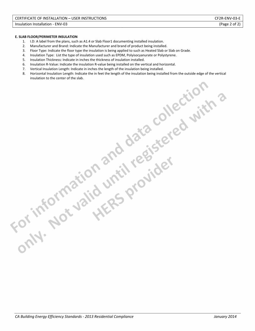
E. SLAB FLOOR/PERIMETER INSULATION 1. I.D: A label from the plans, such as A1.4 or Slab Floor1 documenting installed insulation. 2. Manufacturer and Brand: Indicate the Manufacturer and brand of product being installed. 3. Floor Type: Indicate the floor type the insulation is being applied to such as Heated Slab or Slab on Grade. 4. Insulation Type: List the type of insulation used such as EPDM, Polyisocyanurate or Polystyrene. 5. Insulation Thickness: Indicate in inches the thickness of insulation installed. 6. Insulation R‐Value: Indicate the insulation R‐value being installed on the vertical and horizontal. 7. Vertical Insulation Length: Indicate in inches the length of the insulation being installed. 8. Horizontal Insulation Length: Indicate the in feet the length of the insulation being installed from the outside edge of the vertical
insulation to the center of the slab.
CERTIFICATE OF INSTALLATION – DATA FIELD DEFINITIONS AND CALCULATIONS CF2R‐ENV‐03‐E Insulation Installation ‐ ENV‐03 (Page 1 of 5)
CA Building Energy Efficiency Standards ‐ 2013 Residential Compliance January 2014
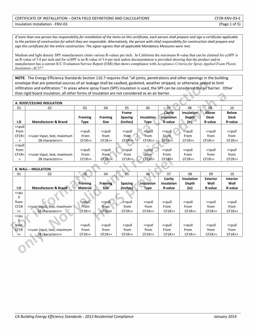
If more than one person has responsibility for installation of the items on this certificate, each person shall prepare and sign a certificate applicable to the portion of construction for which they are responsible. Alternatively, the person with chief responsibility for construction shall prepare and sign this certificate for the entire construction. The signer agrees that all applicable Mandatory Measures were met. Medium and light density SPF manufacturers claim various R-values per inch. In California the maximum R-value that can be claimed for ccSPF is an R-value of 5.8 per inch and for ocSPF is an R-value of 3.6 per inch unless documentation is provided showing that the product and/or manufacturer has a current ICC Evaluation Service Report (ESR) that shows compliance with Acceptance Criteria for Spray-Applied Foam Plastic Insulation--AC377 NOTE: The Energy Efficiency Standards Section 110.7 requires that “all joints, penetrations and other openings in the building envelope that are potential sources of air leakage shall be caulked, gasketed, weather stripped, or otherwise sealed to limit infiltration and exfiltration.” In areas where spray Foam (SPF) insulation is used, the SPF can be considered the air barrier. Other than rigid board insulation, all other forms of insulation are not considered as an air barrier. A. ROOF/CEILING INSULATION 01 02 03 04 05 06 07 08 09 10
I.D Manufacturer & Brand Framing Type
Framing Size
Frame Spacing (inches)
Insulation Type
Cavity Insulation R‐value
Insulation Depth (in)
Above Deck
R‐value
Below Deck
R‐value <<pull from CF1R>
> <<user input, text, maximum
28 characters>>
<<pull. From
CF1R>>
<<pull from
CF1R>>
<<pull from
CF1R>>
<<pull from
CF1R>>
<<pull From
CF1R>>
<<pull From
CF1R>>
<<pull from
CF1R>>
<<pull from
CF1R>> <<pull from CF1R>
> <<user input, text, maximum
28 characters>>
<<pull. From
CF1R>>
<<pull from
CF1R>>
<<pull from
CF1R>>
<<pull from
CF1R>>
<<pull From
CF1R>>
<<pull From
CF1R>>
<<pull from
CF1R>>
<<pull from
CF1R>> B. WALL – INSULATION 01 02 03 04 05 06 07 08 09 10
I.D Manufacturer & Brand Framing Material
Framing Size
Spacing (inches)
Insulation Type
Cavity Insulation R‐value
Insulation Depth (in)
Exterior Wall
R‐value
Interior Wall
R‐value <<pull
from CF1R>>
<<user input, text, maximum 28 characters>>
<<pull. From
CF1R>>
<<pull from
CF1R>>
<<pull from
CF1R>>
<<pull from
CF1R>>
<<pull From CF1R>>
<<pull From CF1R>>
<<pull from
CF1R>>
<<pull from
CF1R>> <<pull
from CF1R>>
<<user input, text, maximum 28 characters>>
<<pull. From
CF1R>>
<<pull from
CF1R>>
<<pull from
CF1R>>
<<pull from
CF1R>>
<<pull From CF1R>>
<<pull From CF1R>>
<<pull from
CF1R>>
<<pull from
CF1R>>
CERTIFICATE OF INSTALLATION – DATA FIELD DEFINITIONS AND CALCULATIONS CF2R‐ENV‐03‐E Insulation Installation ‐ ENV‐03 (Page 2 of 5)
CA Building Energy Efficiency Standards ‐ 2013 Residential Compliance January 2014
C. MASS – INSULATION 01 02 03 04 05 06 07 08
I.D Manufacturer & Brand Location
Mass Thickness
(in)
Furring Strip Type/ Depth
(in) Insulation
Type
Exterior Insulation R‐value
Interior Insulation R‐value
<<pull
from CF1R>>
<<user input, text, maximum 28 characters>>
<<pull. From
CF1R>>
<<pull from
CF1R>>
<<pull from
CF1R>>
<<pull from
CF1R>>
<<pull From CF1R>>
<<pull From CF1R>>
<<pull
from CF1R>>
<<user input, text, maximum 28 characters>>
<<pull. From
CF1R>> <<pull from CF1R>>
<<pull from CF1R>>
<<pull from CF1R>>
<<pull From CF1R>>
<<pull From CF1R>>
D. RAISED FLOOR ‐ INSULATION 01 02 03 04 05 06 07 08 09 10
I.D Manufacturer & Brand Framing Material
Framing Size
Spacing (inches)
Insulation Type
Cavity Insulation R‐value
Insulation Depth (in)
Exterior Floor R‐value
Interior Floor R‐value
<<pull
from CF1R>>
<<user input, text, maximum 28 characters>>
<<pull. From
CF1R>>
<<pull from
CF1R>>
<<pull from
CF1R>>
<<pull from
CF1R>>
<<pull From CF1R>>
<<pull From CF1R>>
<<pull from
CF1R>>
<<pull from
CF1R>> <<pull
from CF1R>>
<<user input, text, maximum 28 characters>>
<<pull. From
CF1R>>
<<pull from
CF1R>>
<<pull from
CF1R>>
<<pull from
CF1R>>
<<pull From CF1R>>
<<pull From CF1R>>
<<pull from
CF1R>>
<<pull from
CF1R>> E. SLAB FLOOR/PERIMETER INSULATION (SEE F. FOR INSULATION REQUIREMENTS FOR HEATED SLABS) 01 02 03 04 05 06 07 08
I.D Manufacturer & Brand Floor type Insulation
Type Insulation
Depth (inches) Insulation R‐Value
Vertical Insulation length (in)
Horizontal Insulation Length (ft)
<<pull
from CF1R>>
<<user input, text, maximum 28 characters>>
<<pull. From
CF1R>>
<<pull from
CF1R>>
<<pull from
CF1R>>
<<pull from
CF1R>>
<<pull From CF1R>>
<<pull From CF1R>>
<<pull
from CF1R>>
<<user input, text, maximum 28 characters>>
<<pull. From
CF1R>> <<pull from CF1R>>
<<pull from CF1R>>
<<pull from CF1R>>
<<pull From CF1R>>
<<pull From CF1R>>
F. HEATED SLABS ‐ INSULATION 01 All heated slabs shall be insulated as required by Section 110.8(g). Footings must meet required insulation levels.
02 Insulation shall be installed from the top of the slab, down 16 inches or to the frost line, whichever is greater. Climate zones 1‐5 requires R‐5, climate zone 16 requires R‐10.
03 Alternatively, vertical insulation from top of slab at inside edge of outside wall down to the top of the horizontal insulation. Horizontal insulation from the outside edge of the vertical insulation extending 4 feet toward the center of the slab in a direction normal to the outside of the building in plan view. Climate zones 1‐5 require R‐5, climate zone 16 requires R‐10 vertical and R‐7 horizontal.
The responsible person’s signature on this document indicates that the installed insulation meets both the R‐value and the installation criteria specified in Table F HEATED SLAB – INSULATION.
CERTIFICATE OF INSTALLATION – DATA FIELD DEFINITIONS AND CALCULATIONS CF2R‐ENV‐03‐E Insulation Installation ‐ ENV‐03 (Page 3 of 5)
CA Building Energy Efficiency Standards ‐ 2013 Residential Compliance January 2014
G. MINIMUM MANDATORY MEASURES 01 Insulation ‐ 110.8(a): All installed Insulation is certified and listed with Department of Consumer Affairs, Standards for Insulating Material. 02 Insulation ‐ 110.8(b): Urea formaldehyde foam insulation is protected by 4 mil polyethylene vapor retarder. 03 Insulation ‐ 110.8(c): Flame spread and smoke density requirements of CBC are met. 02 Raised Floor ‐ 150.0(d): All raised wood‐frame floor have a minimum R‐19 insulation or equivalent U‐factor
03 Slab Floor/Perimeter ‐ 150.0(l): Water absorption rate for the insulation material alone without facings is no greater than 0.3%; water vapor permeance rate is no greater than 2.0 perm/inch and is protected from physical damage and UV light deterioration.
04 Above Grade Exterior Wall ‐ 150.0(c)1: All 2x4 wood‐frame walls have a minimum R‐13 insulation or equivalent U‐factor. 05 Above Grade Exterior Wall ‐ 150.0(c)2: All 2x6 wood‐frame walls have a minimum R‐19 insulation or equivalent U‐factor. 06 Ceiling/Rafter Roof ‐ 150.0(a)1: All wood‐frame ceiling have a minimum R‐30 insulation or equivalent U‐factor.
07 Vapor Retarder ‐ 150(g)1: Class I or II vapor retarder installed on conditioned space side of insulation in exterior walls, vented attics, and unvented attics with air‐impermeable insulation in Climate Zones 14 and 16.
08 Vapor Retarder ‐ 150(g)2: Class I or II vapor retarder installed on earth floor of unvented crawlspaces in Climate Zones 1‐16.
09 Vapor Retarder ‐ 150(g)3: Class I or II vapor retarder installed on earth floor of raised floor buildings with controlled ventilation crawlspaces.
10
Heated Slabs ‐ 110.8(g): All heated slabs shall be insulated as required. Insulation shall be installed from the top of the slab, down 16 inches or to the frost line, whichever is greater. Climate zones 1‐5
require R‐5, climate zone 16 requires R‐10. Alternatively, vertical insulation from top of slab at inside edge of outside wall down to the top of the horizontal insulation.
Horizontal insulation from the outside edge of the vertical insulation extending 4 feet toward the center of the slab in a direction normal to the outside of the building in plan view. Climate zones 1‐5 require R‐5, climate zone 16 requires R‐10 vertical and R‐7 horizontal.
The responsible person’s signature on this compliance document affirms that all applicable requirements in this table have been met. H. INSTALLED INSULATION 01 Installed insulation R‐values are the same or greater than listed on the CF1R. 02 No gaps or voids between the insulation and framing. 03 No gaps between the sides or ends of batts.
04 Loose‐fill insulation must be installed to the minimum installed weight per square foot (density) of the manufacturer's cut sheet for the proposed R‐value.
05 Batt insulation is not compressed (no stuffing of the insulation into the cavity) and is installed to its full thickness. 06 Insulation is cut around obstructions such as electrical boxes. 07 Batt insulation is delaminated around all plumbing and electrical lines in ceilings, walls and floors. 08 Band joists are insulated to the same R‐value as the wall. 09 In all narrow cavities the insulation shall be cut to fit or filled with expanding foam. 10 Insulation was installed per manufacturer instructions.
The responsible person’s signature on this compliance document affirms that all applicable requirements in this table have been met. I. WALL INSULATION
01 When allowed by manufacturer, Low expanding foam shall be used to fill gaps and voids around windows and doors. If not, the cavity must be air tight and filled completely with insulation. Batts must be cut to width. No stuffing allowed.
02 Installed wall insulation before installing tubs, showers and fireplaces.
03 Electric Panel on walls separating conditioned and nonconditioned space are sealed and insulated behind the panel with rigid insulation or expanding foam.
04 All walls of interior closets vented to the outside for HVAC or water heating equipment have the same R‐value and air barrier as the exterior walls and ceiling. Doors are insulated and weather stripped.
05 Ducting not allowed in exterior walls unless insulated to R6 or greater and the insulation and duct are not crushed. Ducting not allowed in 2x4 wall assemblies.
06 Corner channels, wall intersections, and double sided shear walls insulated to the required R‐value before enclosing the wall. 07 Insulation that does not fill the cavity placed against exterior air barrier. 08 Band joists are insulated to the same R‐value as the walls.
The responsible person’s signature on this compliance document affirms that all applicable requirements in this table have been met.
CERTIFICATE OF INSTALLATION – DATA FIELD DEFINITIONS AND CALCULATIONS CF2R‐ENV‐03‐E Insulation Installation ‐ ENV‐03 (Page 4 of 5)
CA Building Energy Efficiency Standards ‐ 2013 Residential Compliance January 2014
J. CEILING/ROOF INSULATION 01 Insulation extends to the outside edge of the exterior top plates and is flush against any ventilation dams/baffles. 02 Insulation is in direct contact with ceiling, so there are no gaps between the ceiling and the insulation. 03 For chimneys and flues, the insulation is in contact with the sheet metal collar.
04 Can lights are covered with insulation to the same depth as required by the CF1R for ceiling insulation. If not an area weighted calculation is required to be turned in with this form.
05 Walkways and mechanical platforms insulated to the same R‐value as required for the ceiling. If not an area weighted calculation is required to be turned in with this form.
06 Insulate a soffit by adding an air barrier and cover with insulation, or insulate the entire soffit including floor and walls.
07 Knee walls and skylight shafts are insulated to the wall R‐value and in full contact with the interior air barrier. If framing on these surfaces is laid flat batt insulation is cut to fit around the framing. Batt insulation is not allowed to be draped over the framing.
08 Attic access doors insulated to the same R‐value as ceiling. The insulation is permanently attached using adhesive or mechanical fasteners. 09 Attic access must be surrounded with a dam at least the same depth as the insulation to prevent loss of ceiling insulation. 10 Batt insulation cut to fit around cross bracings and truss webs in attic.
The responsible person’s signature on this compliance document affirms that all applicable requirements in this table have been met. K. RAISED FLOOR INSULATION 01 Insulation in full contact with subfloor. 02 Insulation hangers spaced at 18 inches or less, insulation hangers must not compress insulation. 03 If netting or mesh is used, the cavity under the floor is filled and in contact with the subfloor.
04 If the basement is conditioned the walls adjacent to the crawlspace must meet minimum wall R‐value requirements. This includes framed stem walls, and vertical concrete retaining walls.
05 If access to the crawl space is from the conditioned area, the raised floor must have an airtight insulated access hatch. The responsible person’s signature on this compliance document affirms that all applicable requirements in this table have been met. L. FLOOR ABOVE GARAGE INSULATION QUALITY 01 Insulation must be in full contact with subfloor if the air barrier is at the band joist at the garage house wall. 02 Insulation hangers spaced at 18 inches or less, insulation hangers must not compress insulation. 03 If netting or mesh is used, the cavity under the floor is filled and in contact with the subfloor.
04 If air barrier is at the perimeter of the garage, below conditioned subfloor, the insulation is placed on the garage ceiling. Perimeter of subfloor is also insulated.
The responsible person’s signature on this compliance document affirms that all applicable requirements in this table have been met. M. CANTILEVERED FLOOR INSULATION QUALITY
01 Insulation in full contact with cantilevered subfloor. Insulation hangers spaced at 18 inches or less, insulation hangers do not compress insulation.
02 If netting or mesh is used, the cavity under the floor is filled and in contact with the subfloor.
03 Sealed Blocking is installed between joists where wall rim joist would be located in the absence of a cantilever. Insulation is placed on both sides of this block.
The responsible person’s signature on this compliance document affirms that all applicable requirements in this table have been met. N. ATTACHED PORCH ROOF INSULATION QUALITY 01 Exterior insulated wall at the intersection of the porch roof is fully insulated above, below and behind the roof line. 02 Where truss framing is used, airtight blocking is at the top and bottom of each wall/roof section and insulated.
The responsible person’s signature on this compliance document affirms that all applicable requirements in this table have been met.
CERTIFICATE OF INSTALLATION – DATA FIELD DEFINITIONS AND CALCULATIONS CF2R‐ENV‐03‐E Insulation Installation ‐ ENV‐03 (Page 5 of 5)
CA Building Energy Efficiency Standards ‐ 2013 Residential Compliance January 2014
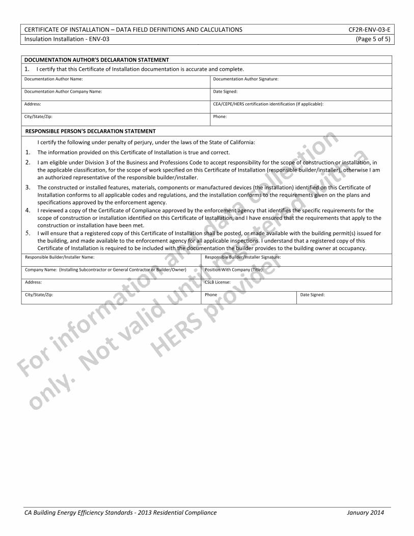
DOCUMENTATION AUTHOR'S DECLARATION STATEMENT
1. I certify that this Certificate of Installation documentation is accurate and complete.
Documentation Author Name: Documentation Author Signature:
Documentation Author Company Name: Date Signed:
Address: CEA/CEPE/HERS certification identification (If applicable):
City/State/Zip: Phone:
RESPONSIBLE PERSON'S DECLARATION STATEMENT
I certify the following under penalty of perjury, under the laws of the State of California:
1. The information provided on this Certificate of Installation is true and correct.
2. I am eligible under Division 3 of the Business and Professions Code to accept responsibility for the scope of construction or installation, in the applicable classification, for the scope of work specified on this Certificate of Installation (responsible builder/installer), otherwise I am an authorized representative of the responsible builder/installer.
3. The constructed or installed features, materials, components or manufactured devices (the installation) identified on this Certificate of Installation conforms to all applicable codes and regulations, and the installation conforms to the requirements given on the plans and specifications approved by the enforcement agency.
4. I reviewed a copy of the Certificate of Compliance approved by the enforcement agency that identifies the specific requirements for the scope of construction or installation identified on this Certificate of Installation, and I have ensured that the requirements that apply to the construction or installation have been met.
5. I will ensure that a registered copy of this Certificate of Installation shall be posted, or made available with the building permit(s) issued for the building, and made available to the enforcement agency for all applicable inspections. I understand that a registered copy of this Certificate of Installation is required to be included with the documentation the builder provides to the building owner at occupancy.
Responsible Builder/Installer Name: Responsible Builder/Installer Signature:
Company Name: (Installing Subcontractor or General Contractor or Builder/Owner) Position With Company (Title):
Address: CSLB License:
City/State/Zip: Phone Date Signed:
STATE OF CALIFORNIA
ROOFING-RADIANT BARRIER CEC-CF2R-ENV-04-E (Revised 06/13) CALIFORNIA ENERGY COMMISSION
CERTIFICATE OF INSTALLATION CF2R‐ENV‐04‐E Roofing‐Radiant Barrier (Page 1 of 2)Project Name: Enforcement Agency: Permit Number:
Dwelling Address: City Zip Code
Registration Number: Registration Date/Time: HERS Provider: CA Building Energy Efficiency Standards ‐ 2013 Residential Compliance January 2014
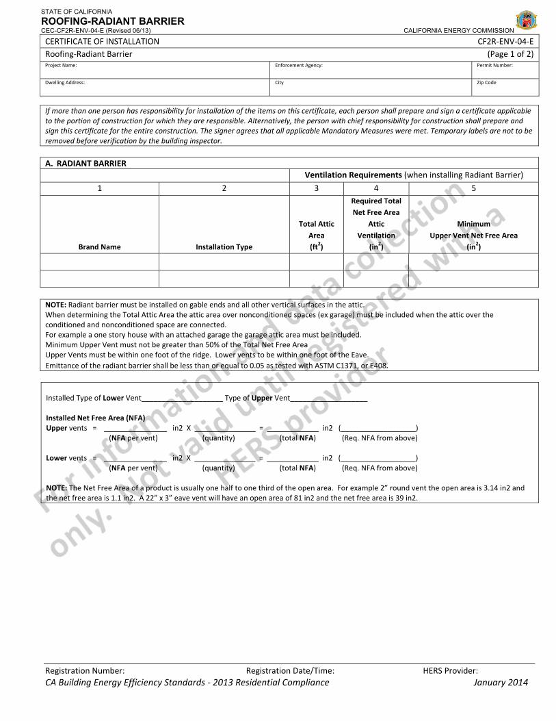
If more than one person has responsibility for installation of the items on this certificate, each person shall prepare and sign a certificate applicable to the portion of construction for which they are responsible. Alternatively, the person with chief responsibility for construction shall prepare and sign this certificate for the entire construction. The signer agrees that all applicable Mandatory Measures were met. Temporary labels are not to be removed before verification by the building inspector. A. RADIANT BARRIER Ventilation Requirements (when installing Radiant Barrier)
1 2 3 4 5
Brand Name Installation Type
Total Attic Area (ft2)
Required Total Net Free Area
Attic Ventilation
(in2)
Minimum Upper Vent Net Free Area
(in2)
NOTE: Radiant barrier must be installed on gable ends and all other vertical surfaces in the attic. When determining the Total Attic Area the attic area over nonconditioned spaces (ex garage) must be included when the attic over the conditioned and nonconditioned space are connected. For example a one story house with an attached garage the garage attic area must be included. Minimum Upper Vent must not be greater than 50% of the Total Net Free Area Upper Vents must be within one foot of the ridge. Lower vents to be within one foot of the Eave. Emittance of the radiant barrier shall be less than or equal to 0.05 as tested with ASTM C1371, or E408. Installed Type of Lower Vent____________________ Type of Upper Vent___________________ Installed Net Free Area (NFA) Upper vents = in2 X = in2 (____ ________) (NFA per vent) (quantity) (total NFA) (Req. NFA from above) Lower vents = in2 X = in2 (____ ________) (NFA per vent) (quantity) (total NFA) (Req. NFA from above) NOTE: The Net Free Area of a product is usually one half to one third of the open area. For example 2” round vent the open area is 3.14 in2 and the net free area is 1.1 in2. A 22” x 3” eave vent will have an open area of 81 in2 and the net free area is 39 in2.
STATE OF CALIFORNIA
ROOFING-RADIANT BARRIER CEC-CF2R-ENV-04-E (Revised 06/13) CALIFORNIA ENERGY COMMISSION
CERTIFICATE OF INSTALLATION CF2R‐ENV‐04‐E Roofing‐Radiant Barrier (Page 2 of 2)Project Name: Enforcement Agency: Permit Number:
Dwelling Address: City Zip Code
Registration Number: Registration Date/Time: HERS Provider: CA Building Energy Efficiency Standards ‐ 2013 Residential Compliance January 2014
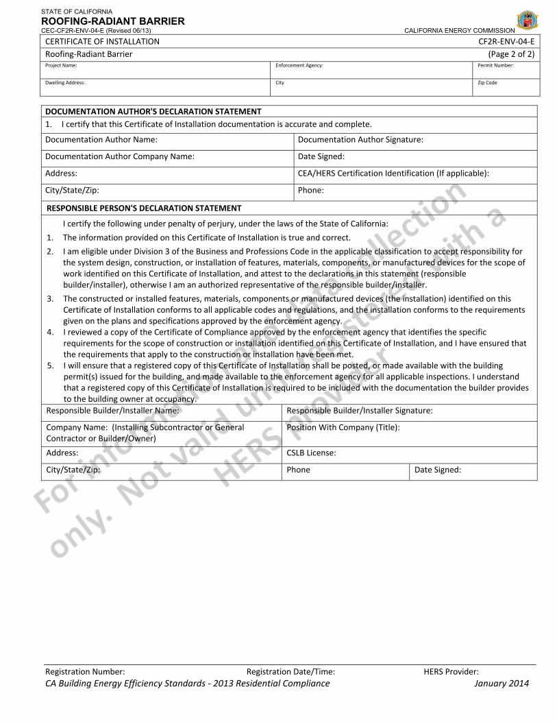
DOCUMENTATION AUTHOR'S DECLARATION STATEMENT1. I certify that this Certificate of Installation documentation is accurate and complete.
Documentation Author Name: Documentation Author Signature:
Documentation Author Company Name: Date Signed:
Address: CEA/HERS Certification Identification (If applicable):
City/State/Zip: Phone:
RESPONSIBLE PERSON'S DECLARATION STATEMENT
I certify the following under penalty of perjury, under the laws of the State of California:
1. The information provided on this Certificate of Installation is true and correct.
2. I am eligible under Division 3 of the Business and Professions Code in the applicable classification to accept responsibility for the system design, construction, or installation of features, materials, components, or manufactured devices for the scope of work identified on this Certificate of Installation, and attest to the declarations in this statement (responsible builder/installer), otherwise I am an authorized representative of the responsible builder/installer.
3. The constructed or installed features, materials, components or manufactured devices (the installation) identified on this Certificate of Installation conforms to all applicable codes and regulations, and the installation conforms to the requirements given on the plans and specifications approved by the enforcement agency.
4. I reviewed a copy of the Certificate of Compliance approved by the enforcement agency that identifies the specific requirements for the scope of construction or installation identified on this Certificate of Installation, and I have ensured that the requirements that apply to the construction or installation have been met.
5. I will ensure that a registered copy of this Certificate of Installation shall be posted, or made available with the building permit(s) issued for the building, and made available to the enforcement agency for all applicable inspections. I understand that a registered copy of this Certificate of Installation is required to be included with the documentation the builder provides to the building owner at occupancy.
Responsible Builder/Installer Name: Responsible Builder/Installer Signature:
Company Name: (Installing Subcontractor or General Contractor or Builder/Owner)
Position With Company (Title):
Address: CSLB License:
City/State/Zip: Phone Date Signed:
CERTIFICATE OF INSTALLATION – USER INSTRUCTIONS CF2R‐ENV‐04‐E Roofing‐Radiant Barrier – ENV‐04 (Page 1 of 1)
CA Building Energy Efficiency Standards ‐ 2013 Residential Compliance January 2014
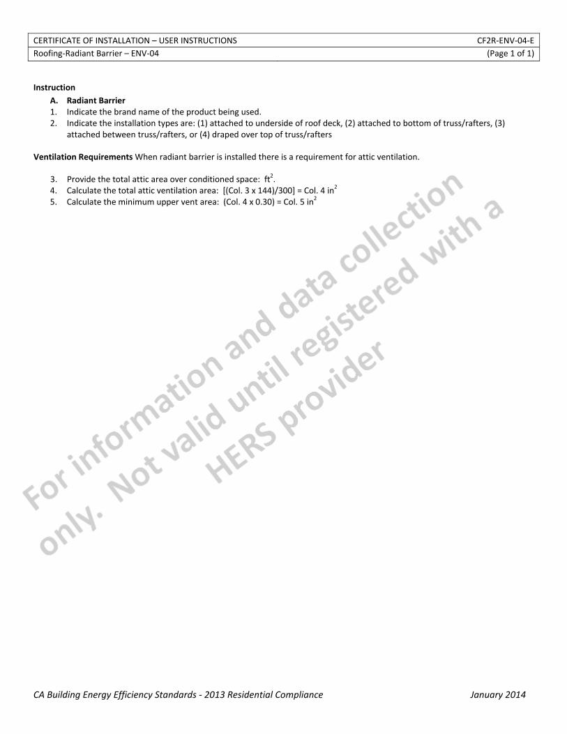
Instruction
A. Radiant Barrier 1. Indicate the brand name of the product being used. 2. Indicate the installation types are: (1) attached to underside of roof deck, (2) attached to bottom of truss/rafters, (3)
attached between truss/rafters, or (4) draped over top of truss/rafters
Ventilation Requirements When radiant barrier is installed there is a requirement for attic ventilation.
3. Provide the total attic area over conditioned space: ft2. 4. Calculate the total attic ventilation area: [(Col. 3 x 144)/300] = Col. 4 in2 5. Calculate the minimum upper vent area: (Col. 4 x 0.30) = Col. 5 in2
STATE OF CALIFORNIA
BUILDING LEAKAGE DIAGNOSTIC TEST CEC-CF2R-ENV-20-H (Revised 06/13) CALIFORNIA ENERGY COMMISSION
CERTIFICATE OF INSTALLATION CF2R‐ENV‐20‐H Building Leakage Diagnostic Test (Page 1 of 2) Project Name: Enforcement Agency: Permit Number:
Dwelling Address: City Zip Code
Registration Number: Registration Date/Time: HERS Provider: CA Building Energy Efficiency Standards ‐ 2013 Residential Compliance January 2014
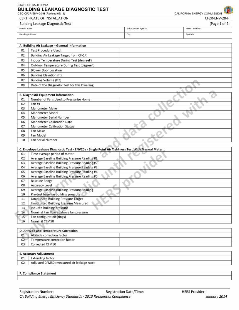
A. Building Air Leakage – General Information 01 Test Procedure Used: 02 Building Air Leakage Target from CF‐1R 03 Indoor Temperature During Test (degreeF) 04 Outdoor Temperature During Test (degreeF) 05 Blower Door Location 06 Building Elevation (ft) 07 Building Volume (ft3) 08 Date of the Diagnostic Test for this Dwelling
B. Diagnostic Equipment Information 01 Number of Fans Used to Pressurize Home 02 Fan #1 03 Manometer Make 04 Manometer Model 05 Manometer Serial Number 06 Manometer Calibration Date 07 Manometer Calibration Status 08 Fan Make 09 Fan Model 10 Fan Serial Number C. Envelope Leakage Diagnostic Test ‐ ENV20a ‐ Single Point Air Tightness Test With Manual Meter 01 Time average period of meter 02 Average Baseline Building Pressure Reading #1 03 Average Baseline Building Pressure Reading #2 04 Average Baseline Building Pressure Reading #3 05 Average Baseline Building Pressure Reading #4 06 Average Baseline Building Pressure Reading #5 07 Baseline Range 08 Accuracy Level 09 Average Baseline Building Pressure Reading 10 Pre‐test baseline building pressure 11 Unadjusted Building Pressure Target 12 Unadjusted Building Pressure Measured 13 Induced building pressure 14 Nominal Fan flow at above fan pressure 15 Fan configuration (rings) 16 Nominal CFM50 D. Altitude and Temperature Correction 01 Altitude correction factor 02 Temperature correction factor 03 Corrected CFM50 E. Accuracy Adjustment 01 Extending factor 02 Adjusted CFM50 (measured air leakage rate)
F. Compliance Statement
STATE OF CALIFORNIA
BUILDING LEAKAGE DIAGNOSTIC TEST CEC-CF2R-ENV-20-H (Revised 06/13) CALIFORNIA ENERGY COMMISSION
CERTIFICATE OF INSTALLATION CF2R‐ENV‐20‐H Building Leakage Diagnostic Test (Page 2 of 2) Project Name: Enforcement Agency: Permit Number:
Dwelling Address: City Zip Code
Registration Number: Registration Date/Time: HERS Provider: CA Building Energy Efficiency Standards ‐ 2013 Residential Compliance January 2014
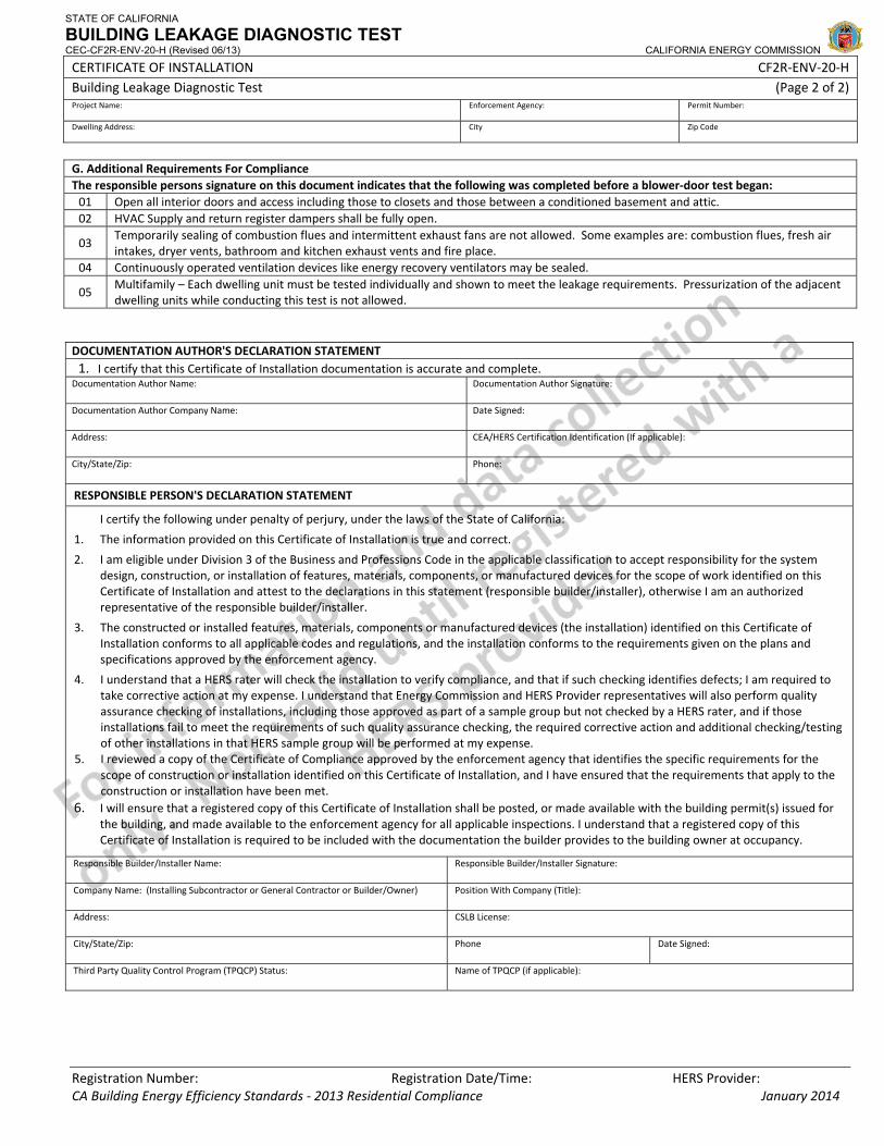
G. Additional Requirements For Compliance The responsible persons signature on this document indicates that the following was completed before a blower‐door test began: 01 Open all interior doors and access including those to closets and those between a conditioned basement and attic. 02 HVAC Supply and return register dampers shall be fully open.
03 Temporarily sealing of combustion flues and intermittent exhaust fans are not allowed. Some examples are: combustion flues, fresh air intakes, dryer vents, bathroom and kitchen exhaust vents and fire place.
04 Continuously operated ventilation devices like energy recovery ventilators may be sealed.
05 Multifamily – Each dwelling unit must be tested individually and shown to meet the leakage requirements. Pressurization of the adjacent dwelling units while conducting this test is not allowed.
DOCUMENTATION AUTHOR'S DECLARATION STATEMENT1. I certify that this Certificate of Installation documentation is accurate and complete.
Documentation Author Name: Documentation Author Signature:
Documentation Author Company Name: Date Signed:
Address: CEA/HERS Certification Identification (If applicable):
City/State/Zip: Phone:
RESPONSIBLE PERSON'S DECLARATION STATEMENT
I certify the following under penalty of perjury, under the laws of the State of California:
1. The information provided on this Certificate of Installation is true and correct.
2. I am eligible under Division 3 of the Business and Professions Code in the applicable classification to accept responsibility for the system design, construction, or installation of features, materials, components, or manufactured devices for the scope of work identified on this Certificate of Installation and attest to the declarations in this statement (responsible builder/installer), otherwise I am an authorized representative of the responsible builder/installer.
3. The constructed or installed features, materials, components or manufactured devices (the installation) identified on this Certificate of Installation conforms to all applicable codes and regulations, and the installation conforms to the requirements given on the plans and specifications approved by the enforcement agency.
4. I understand that a HERS rater will check the installation to verify compliance, and that if such checking identifies defects; I am required to take corrective action at my expense. I understand that Energy Commission and HERS Provider representatives will also perform quality assurance checking of installations, including those approved as part of a sample group but not checked by a HERS rater, and if those installations fail to meet the requirements of such quality assurance checking, the required corrective action and additional checking/testing of other installations in that HERS sample group will be performed at my expense.
5. I reviewed a copy of the Certificate of Compliance approved by the enforcement agency that identifies the specific requirements for the scope of construction or installation identified on this Certificate of Installation, and I have ensured that the requirements that apply to the construction or installation have been met.
6. I will ensure that a registered copy of this Certificate of Installation shall be posted, or made available with the building permit(s) issued for the building, and made available to the enforcement agency for all applicable inspections. I understand that a registered copy of this Certificate of Installation is required to be included with the documentation the builder provides to the building owner at occupancy.
Responsible Builder/Installer Name: Responsible Builder/Installer Signature:
Company Name: (Installing Subcontractor or General Contractor or Builder/Owner) Position With Company (Title):
Address: CSLB License:
City/State/Zip: Phone Date Signed:
Third Party Quality Control Program (TPQCP) Status: Name of TPQCP (if applicable):

CERTIFICATE OF INSTALLATION ‐ USER INSTRUCTIONS CF2R‐ENV‐20‐H Building Leakage Diagnostic Test ‐ ENV‐20a (Page 1 of 3)
CA Building Energy Efficiency Standards ‐ 2013 Residential Compliance January 2014
Instructions for ENV20 Section A. Building Air Leakage – General Information
1. Select the appropriate test procedure. This selection will determine which version of this document will be used (a, b, c, d, or e) and therefore which data must be collected. Note that single‐point tests can only be used under certain conditions. Note that newer manometers have automatic functions for compensating for baseline (automatic baseline) and compensating for house pressures other than the target (@50 Pa). It is preferable to use these, when available, however if these automatic functions are to be used, they must be used for BOTH automatic baseline and pressure compensation.
2. This number is automatically pulled from the performance approach Certificate of Compliance and is the target maximum that was entered by the documentation author. If this number cannot be achieved, the performance compliance calculations can be redone with a higher number or without the requirement for building air leakage.
3. Enter the indoor temperature measured at the time that the building air leakage test was performed. 4. Enter the outdoor temperature measured at the time that the building air leakage test was performed. 5. Provide a brief description of the location where the blower door was installed for the test. Examples: “front entry door on west side of
house”, “door between house and garage”, “large window in family room”. 6. Enter the building elevation use the value for the closest city found in Joint Appendix JA2.2. Only elevations higher than 5000 feet
require an adjustment to the calculations. 7. This number is automatically pulled from the performance approach Certificate of Compliance. It is used to calculate air changes. 8. Enter the date that the building leakage test data was collected.
Section B. Diagnostic Equipment Information
1. Enter the number of blower door fan systems required to run simultaneously to pressurize the home for the building air leakage test. If more than one system is used, the fan flow numbers need to be manually added together, unless blower door software is used that will accommodate multiple fan systems running simultaneously.
2. Enter the appropriate information for each fan system used in the following rows. 3. Enter the make (brand) of the manometer used to collect the building air leakage data. Examples: Retrotec, Energy Conservatory. 4. Enter the model of the manometer used to collect the building air leakage data. Examples: DM‐2 Mark II, DG700. 5. Enter the serial number of the manometer used to collect the building air leakage data. 6. Enter the most recent date that the manometer was calibrated by following manufacturer’s calibration specifications. 7. This field is automatically filled. If the calibration date was more than 12 months prior to the test date entered in Row A.8, above, an
error will appear. 8. Enter the make (brand) of the fan used to collect the building air leakage data. Examples: Retrotec, Energy Conservatory. 9. Enter the model of the fan used to collect the building air leakage data. Examples: US1000, Q46, BD3, BD4.
Section C. Envelope Leakage Test (ENV20a) 1. Enter the time average period used on the manometer during the test. Must be at least 10 seconds. 2. Enter the first of five baseline building pressure readings. 3. Enter the second of five baseline building pressure readings. 4. Enter the third of five baseline building pressure readings. 5. Enter the fourth of five baseline building pressure readings. 6. Enter the fifth of five baseline building pressure readings. 7. This field is automatically calculated when using the online form. The equation used to calculate this value in the field equals [Largest
value of (C. 2 through C. 6)] –[ smallest value of (C. 2 through C. 6)] = Baseline Range 8. This field is automatically calculated when using the online form. The values entered the field C. 8 equals a. if row C. 7 > 5.0, enter
“Standard”; b. if row C. 7 ≥ 5 and ≤ 10, enter “Reduced”; c. if row C. 7 > 10, “cannot use single‐point test”, do not proceed. 9. This field is automatically calculated when using the online form. The equation used to calculate this value in the field equals (C.2+ C.3+
C.4+ C.5+ C.6)/5 = Average Baseline Building Pressure Reading 10. Enter the pre‐test baseline building pressure. The protocols allow the average from Row C.9 or a newly measured number to be used. 11. This field is automatically calculated when using the online form. The equation used to calculate this value in the field equals ‐50pa – C.9
= Pre‐test building pressure 12. Enter the measured unadjusted building pressure straight from the manometer. It should be as close to the target from Row C.11 as
possible. Note that the protocols require depressurization of the envelope. All blower door induced pressures are to be negative relative to outside.
13. This field is automatically calculated when using the online form. The equation used to calculate this value in the field equals Row C.12 – C.9 = Induced Building pressure.
14. Enter the fan flow from the manometer that corresponds to the measured unadjusted building pressure from Row C.12. 15. Enter the fan configuration (rings) that was used during the data acquisition. Examples: Ring A, Ring A1 16. This field is automatically calculated when using the online form. The equation used to calculate this value in the field equals (50/Row
C.13) ^0.65 x row C. 14 = Nominal CFM50
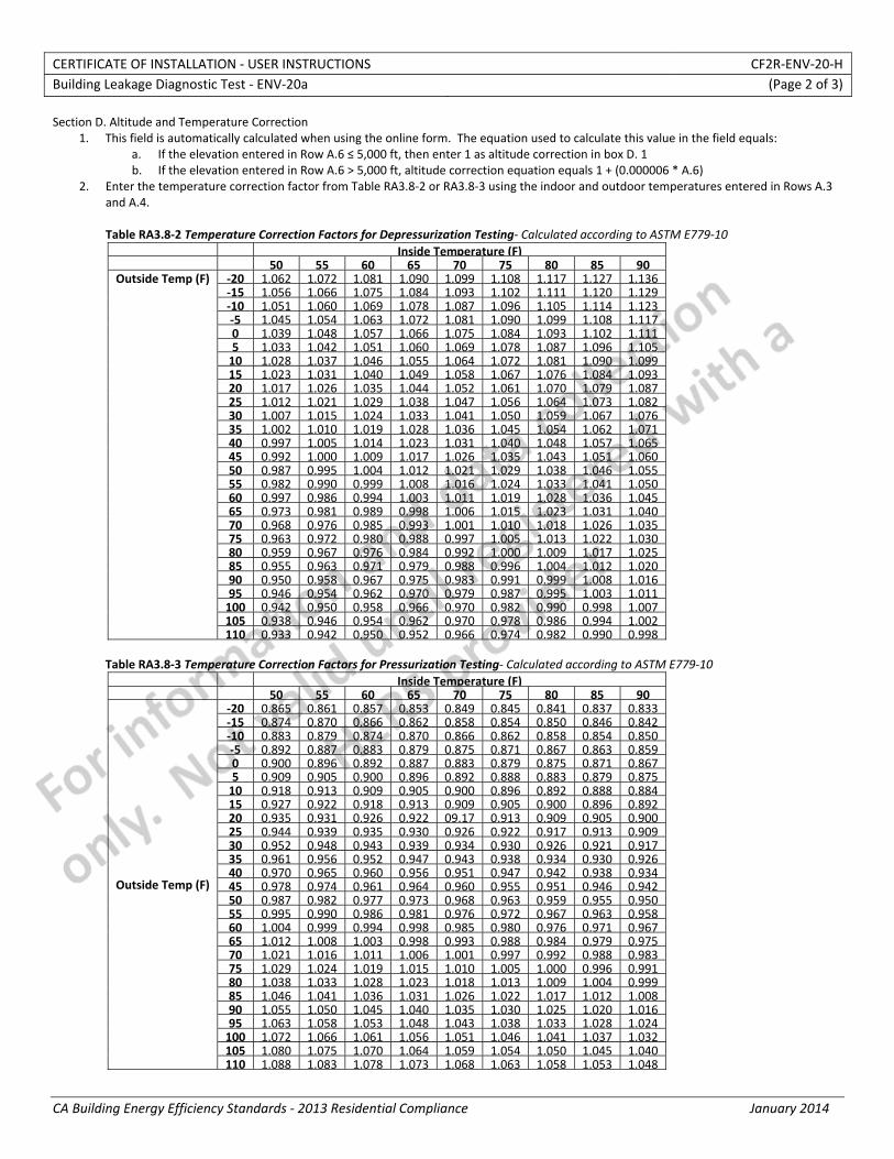
CERTIFICATE OF INSTALLATION ‐ USER INSTRUCTIONS CF2R‐ENV‐20‐H Building Leakage Diagnostic Test ‐ ENV‐20a (Page 2 of 3)
CA Building Energy Efficiency Standards ‐ 2013 Residential Compliance January 2014
Section D. Altitude and Temperature Correction 1. This field is automatically calculated when using the online form. The equation used to calculate this value in the field equals:
a. If the elevation entered in Row A.6 ≤ 5,000 ft, then enter 1 as altitude correction in box D. 1 b. If the elevation entered in Row A.6 > 5,000 ft, altitude correction equation equals 1 + (0.000006 * A.6)
2. Enter the temperature correction factor from Table RA3.8‐2 or RA3.8‐3 using the indoor and outdoor temperatures entered in Rows A.3 and A.4. Table RA3.8‐2 Temperature Correction Factors for Depressurization Testing‐ Calculated according to ASTM E779‐10
Inside Temperature (F) 50 55 60 65 70 75 80 85 90
Outside Temp (F) ‐20 1.062 1.072 1.081 1.090 1.099 1.108 1.117 1.127 1.136 ‐15 1.056 1.066 1.075 1.084 1.093 1.102 1.111 1.120 1.129 ‐10 1.051 1.060 1.069 1.078 1.087 1.096 1.105 1.114 1.123 ‐5 1.045 1.054 1.063 1.072 1.081 1.090 1.099 1.108 1.117 0 1.039 1.048 1.057 1.066 1.075 1.084 1.093 1.102 1.111 5 1.033 1.042 1.051 1.060 1.069 1.078 1.087 1.096 1.105 10 1.028 1.037 1.046 1.055 1.064 1.072 1.081 1.090 1.099 15 1.023 1.031 1.040 1.049 1.058 1.067 1.076 1.084 1.093 20 1.017 1.026 1.035 1.044 1.052 1.061 1.070 1.079 1.087 25 1.012 1.021 1.029 1.038 1.047 1.056 1.064 1.073 1.082 30 1.007 1.015 1.024 1.033 1.041 1.050 1.059 1.067 1.076 35 1.002 1.010 1.019 1.028 1.036 1.045 1.054 1.062 1.071 40 0.997 1.005 1.014 1.023 1.031 1.040 1.048 1.057 1.065 45 0.992 1.000 1.009 1.017 1.026 1.035 1.043 1.051 1.060 50 0.987 0.995 1.004 1.012 1.021 1.029 1.038 1.046 1.055 55 0.982 0.990 0.999 1.008 1.016 1.024 1.033 1.041 1.050 60 0.997 0.986 0.994 1.003 1.011 1.019 1.028 1.036 1.045 65 0.973 0.981 0.989 0.998 1.006 1.015 1.023 1.031 1.040 70 0.968 0.976 0.985 0.993 1.001 1.010 1.018 1.026 1.035 75 0.963 0.972 0.980 0.988 0.997 1.005 1.013 1.022 1.030 80 0.959 0.967 0.976 0.984 0.992 1.000 1.009 1.017 1.025 85 0.955 0.963 0.971 0.979 0.988 0.996 1.004 1.012 1.020 90 0.950 0.958 0.967 0.975 0.983 0.991 0.999 1.008 1.016 95 0.946 0.954 0.962 0.970 0.979 0.987 0.995 1.003 1.011 100 0.942 0.950 0.958 0.966 0.970 0.982 0.990 0.998 1.007 105 0.938 0.946 0.954 0.962 0.970 0.978 0.986 0.994 1.002 110 0.933 0.942 0.950 0.952 0.966 0.974 0.982 0.990 0.998
Table RA3.8‐3 Temperature Correction Factors for Pressurization Testing‐ Calculated according to ASTM E779‐10
Inside Temperature (F) 50 55 60 65 70 75 80 85 90
Outside Temp (F)
‐20 0.865 0.861 0.857 0.853 0.849 0.845 0.841 0.837 0.833 ‐15 0.874 0.870 0.866 0.862 0.858 0.854 0.850 0.846 0.842 ‐10 0.883 0.879 0.874 0.870 0.866 0.862 0.858 0.854 0.850 ‐5 0.892 0.887 0.883 0.879 0.875 0.871 0.867 0.863 0.859 0 0.900 0.896 0.892 0.887 0.883 0.879 0.875 0.871 0.867 5 0.909 0.905 0.900 0.896 0.892 0.888 0.883 0.879 0.875 10 0.918 0.913 0.909 0.905 0.900 0.896 0.892 0.888 0.884 15 0.927 0.922 0.918 0.913 0.909 0.905 0.900 0.896 0.892 20 0.935 0.931 0.926 0.922 09.17 0.913 0.909 0.905 0.900 25 0.944 0.939 0.935 0.930 0.926 0.922 0.917 0.913 0.909 30 0.952 0.948 0.943 0.939 0.934 0.930 0.926 0.921 0.917 35 0.961 0.956 0.952 0.947 0.943 0.938 0.934 0.930 0.926 40 0.970 0.965 0.960 0.956 0.951 0.947 0.942 0.938 0.934 45 0.978 0.974 0.961 0.964 0.960 0.955 0.951 0.946 0.942 50 0.987 0.982 0.977 0.973 0.968 0.963 0.959 0.955 0.950 55 0.995 0.990 0.986 0.981 0.976 0.972 0.967 0.963 0.958 60 1.004 0.999 0.994 0.998 0.985 0.980 0.976 0.971 0.967 65 1.012 1.008 1.003 0.998 0.993 0.988 0.984 0.979 0.975 70 1.021 1.016 1.011 1.006 1.001 0.997 0.992 0.988 0.983 75 1.029 1.024 1.019 1.015 1.010 1.005 1.000 0.996 0.991 80 1.038 1.033 1.028 1.023 1.018 1.013 1.009 1.004 0.999 85 1.046 1.041 1.036 1.031 1.026 1.022 1.017 1.012 1.008 90 1.055 1.050 1.045 1.040 1.035 1.030 1.025 1.020 1.016 95 1.063 1.058 1.053 1.048 1.043 1.038 1.033 1.028 1.024 100 1.072 1.066 1.061 1.056 1.051 1.046 1.041 1.037 1.032 105 1.080 1.075 1.070 1.064 1.059 1.054 1.050 1.045 1.040 110 1.088 1.083 1.078 1.073 1.068 1.063 1.058 1.053 1.048
CERTIFICATE OF INSTALLATION ‐ USER INSTRUCTIONS CF2R‐ENV‐20‐H Building Leakage Diagnostic Test ‐ ENV‐20a (Page 3 of 3)
CA Building Energy Efficiency Standards ‐ 2013 Residential Compliance January 2014
3. This field is automatically calculated when using the online form. The equation used to calculate this value in the field equals the product of D.1 * D.2 * C.16.
Section E. Accuracy Adjustment
1. This field is automatically calculated when using the online form. The equation used to calculate this value in the field equals: c. If the accuracy level C.8 = Standard, then enter 1 as accuracy adjustment in box E. 1 d. If the accuracy level C.8 = Reduced, accuracy adjustment equation equals 1+[0.1+(50/C. 14)]
2. This field is automatically calculated when using the online form. The equation used to calculate this value in the field equals the D.3 * E.1. = Adjusted CFM50 Note ‐ This is the number that must be less than or equal to the target building air leakage from the CF‐1R, shown in Row A.2.
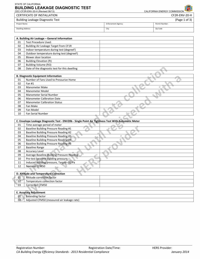
STATE OF CALIFORNIA
BUILDING LEAKAGE DIAGNOSTIC TEST CEC-CF2R-ENV-20-H (Revised 06/13) CALIFORNIA ENERGY COMMISSION
CERTIFICATE OF INSTALLATION CF2R‐ENV‐20‐H Building Leakage Diagnostic Test (Page 1 of 3) Project Name: Enforcement Agency: Permit Number:
Dwelling Address: City Zip Code
Registration Number: Registration Date/Time: HERS Provider:
A. Building Air Leakage – General Information 01 Test Procedure Used: 02 Building Air Leakage Target from CF1R 03 Indoor temperature during test (degreeF) 04 Outdoor temperature during test (degreeF) 05 Blower door location 06 Building Elevation (ft) 07 Building Volume (ft3) 08 Date of the diagnostic test for this dwelling
B. Diagnostic Equipment Information 01 Number of Fans Used to Pressurize Home 02 Fan #1 03 Manometer Make 04 Manometer Model 05 Manometer Serial Number 06 Manometer Calibration Date 07 Manometer Calibration Status 08 Fan Make 09 Fan Model 10 Fan Serial Number
C. Envelope Leakage Diagnostic Test ‐ ENV20b ‐ Single Point Air Tightness Test With Automatic Meter 01 Time average period of meter 02 Baseline Building Pressure Reading #1 03 Baseline Building Pressure Reading #2 04 Baseline Building Pressure Reading #3 05 Baseline Building Pressure Reading #4 06 Baseline Building Pressure Reading #5 07 Baseline Range 08 Accuracy Level 09 Average Baseline Building Pressure Reading 10 Pre‐test baseline building pressure 11 Induced building pressure, Target=‐50 Pa 12 Nominal CFM50
D. Altitude and Temperature Correction 01 Altitude correction factor 02 Temperature correction factor 03 Corrected CFM50
E. Accuracy Adjustment 01 Extending factor 02 Adjusted CFM50 (measured air leakage rate)
CA Building Energy Efficiency Standards ‐ 2013 Residential Compliance January 2014
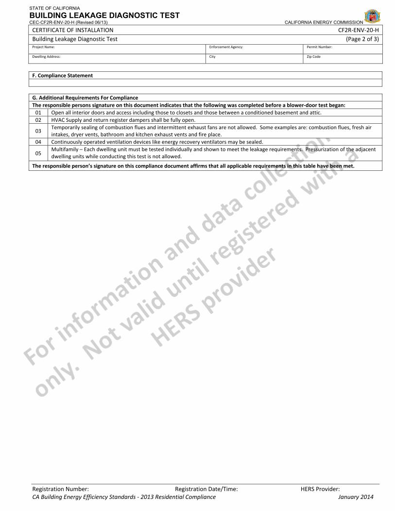
STATE OF CALIFORNIA
BUILDING LEAKAGE DIAGNOSTIC TEST CEC-CF2R-ENV-20-H (Revised 06/13) CALIFORNIA ENERGY COMMISSION
CERTIFICATE OF INSTALLATION CF2R‐ENV‐20‐H Building Leakage Diagnostic Test (Page 2 of 3) Project Name: Enforcement Agency: Permit Number:
Dwelling Address: City Zip Code
Registration Number: Registration Date/Time: HERS Provider:
F. Compliance Statement G. Additional Requirements For Compliance The responsible persons signature on this document indicates that the following was completed before a blower‐door test began: 01 Open all interior doors and access including those to closets and those between a conditioned basement and attic. 02 HVAC Supply and return register dampers shall be fully open.
03 Temporarily sealing of combustion flues and intermittent exhaust fans are not allowed. Some examples are: combustion flues, fresh air intakes, dryer vents, bathroom and kitchen exhaust vents and fire place.
04 Continuously operated ventilation devices like energy recovery ventilators may be sealed.
05 Multifamily – Each dwelling unit must be tested individually and shown to meet the leakage requirements. Pressurization of the adjacent dwelling units while conducting this test is not allowed.
The responsible person’s signature on this compliance document affirms that all applicable requirements in this table have been met.
CA Building Energy Efficiency Standards ‐ 2013 Residential Compliance January 2014
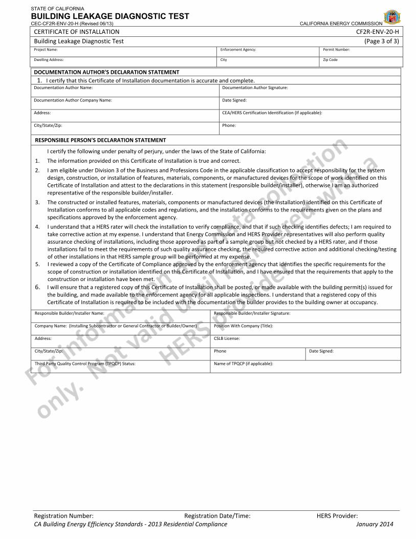
STATE OF CALIFORNIA
BUILDING LEAKAGE DIAGNOSTIC TEST CEC-CF2R-ENV-20-H (Revised 06/13) CALIFORNIA ENERGY COMMISSION
CERTIFICATE OF INSTALLATION CF2R‐ENV‐20‐H Building Leakage Diagnostic Test (Page 3 of 3) Project Name: Enforcement Agency: Permit Number:
Dwelling Address: City Zip Code
Registration Number: Registration Date/Time: HERS Provider: CA Building Energy Efficiency Standards ‐ 2013 Residential Compliance January 2014
DOCUMENTATION AUTHOR'S DECLARATION STATEMENT1. I certify that this Certificate of Installation documentation is accurate and complete.
Documentation Author Name: Documentation Author Signature:
Documentation Author Company Name: Date Signed:
Address: CEA/HERS Certification Identification (If applicable):
City/State/Zip: Phone:
RESPONSIBLE PERSON'S DECLARATION STATEMENT
I certify the following under penalty of perjury, under the laws of the State of California:
1. The information provided on this Certificate of Installation is true and correct.
2. I am eligible under Division 3 of the Business and Professions Code in the applicable classification to accept responsibility for the system design, construction, or installation of features, materials, components, or manufactured devices for the scope of work identified on this Certificate of Installation and attest to the declarations in this statement (responsible builder/installer), otherwise I am an authorized representative of the responsible builder/installer.
3. The constructed or installed features, materials, components or manufactured devices (the installation) identified on this Certificate of Installation conforms to all applicable codes and regulations, and the installation conforms to the requirements given on the plans and specifications approved by the enforcement agency.
4. I understand that a HERS rater will check the installation to verify compliance, and that if such checking identifies defects; I am required to take corrective action at my expense. I understand that Energy Commission and HERS Provider representatives will also perform quality assurance checking of installations, including those approved as part of a sample group but not checked by a HERS rater, and if those installations fail to meet the requirements of such quality assurance checking, the required corrective action and additional checking/testing of other installations in that HERS sample group will be performed at my expense.
5. I reviewed a copy of the Certificate of Compliance approved by the enforcement agency that identifies the specific requirements for the scope of construction or installation identified on this Certificate of Installation, and I have ensured that the requirements that apply to the construction or installation have been met.
6. I will ensure that a registered copy of this Certificate of Installation shall be posted, or made available with the building permit(s) issued for the building, and made available to the enforcement agency for all applicable inspections. I understand that a registered copy of this Certificate of Installation is required to be included with the documentation the builder provides to the building owner at occupancy.
Responsible Builder/Installer Name: Responsible Builder/Installer Signature:
Company Name: (Installing Subcontractor or General Contractor or Builder/Owner) Position With Company (Title):
Address: CSLB License:
City/State/Zip: Phone Date Signed:
Third Party Quality Control Program (TPQCP) Status: Name of TPQCP (if applicable):
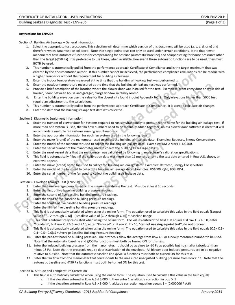
CERTIFICATE OF INSTALLATION‐ USER INSTRUCTIONS CF2R‐ENV‐20‐H Building Leakage Diagnostic Test ‐ ENV‐20b (Page 1 of 3)
CA Building Energy Efficiency Standards ‐ 2013 Residential Compliance January 2014
Instructions for ENV20b Section A. Building Air Leakage – General Information
1. Select the appropriate test procedure. This selection will determine which version of this document will be used (a, b, c, d, or e) and therefore which data must be collected. Note that single‐point tests can only be used under certain conditions. Note that newer manometers have automatic functions for compensating for baseline (automatic baseline) and compensating for house pressures other than the target (@50 Pa). It is preferable to use these, when available, however if these automatic functions are to be used, they must BOTH be used.
2. This number is automatically pulled from the performance approach Certificate of Compliance and is the target maximum that was entered by the documentation author. If this number cannot be achieved, the performance compliance calculations can be redone with a higher number or without the requirement for building air leakage.
3. Enter the indoor temperature measured at the time that the building air leakage test was performed. 4. Enter the outdoor temperature measured at the time that the building air leakage test was performed. 5. Provide a brief description of the location where the blower door was installed for the test. Examples: “front entry door on west side of
house”, “door between house and garage”, “large window in family room”. 6. Enter the building elevation use the value for the closest city found in Joint Appendix JA2.2. Only elevations higher than 5000 feet
require an adjustment to the calculations. 7. This number is automatically pulled from the performance approach Certificate of Compliance. It is used to calculate air changes. 8. Enter the date that the building leakage test data was collected.
Section B. Diagnostic Equipment Information
1. Enter the number of blower door fan systems required to run simultaneously to pressurize the home for the building air leakage test. If more than one system is used, the fan flow numbers need to be manually added together, unless blower door software is used that will accommodate multiple fan systems running simultaneously.
2. Enter the appropriate information for each fan system used in the following rows. 3. Enter the make (brand) of the manometer used to collect the building air leakage data. Examples: Retrotec, Energy Conservatory. 4. Enter the model of the manometer used to collect the building air leakage data. Examples: DM‐2 Mark II, DG700. 5. Enter the serial number of the manometer used to collect the building air leakage data. 6. Enter the most recent date that the manometer was calibrated by following manufacturer’s calibration specifications. 7. This field is automatically filled. If the calibration date was more than 12 months prior to the test date entered in Row A.8, above, an
error will appear. 8. Enter the make (brand) of the fan used to collect the building air leakage data. Examples: Retrotec, Energy Conservatory. 9. Enter the model of the fan used to collect the building air leakage data. Examples: US1000, Q46, BD3, BD4. 10. Enter the serial number of the fan used to collect the building air leakage data.
Section C. Envelope Leakage Test (ENV20b) 1. Enter the time average period used on the manometer during the test. Must be at least 10 seconds. 2. Enter the first of five baseline building pressure readings. 3. Enter the second of five baseline building pressure readings. 4. Enter the third of five baseline building pressure readings. 5. Enter the fourth of five baseline building pressure readings. 6. Enter the fifth of five baseline building pressure readings. 7. This field is automatically calculated when using the online form. The equation used to calculate this value in the field equals [Largest
value of (C. 2 through C. 6)] –[ smallest value of (C. 2 through C. 6)] = Baseline Range 8. This field is automatically calculated when using the online form. The values entered the field C. 8 equals a. if row C. 7 > 5.0, enter
“Standard”; b. if row C. 7 ≥ 5 and ≤ 10, enter “Reduced”; c. if row C. 7 > 10, “cannot use single‐point test”, do not proceed. 9. This field is automatically calculated when using the online form. The equation used to calculate this value in the field equals (C.2+ C.3+
C.4+ C.5+ C.6)/5 = Average Baseline Building Pressure Reading 10. Enter the pre‐test baseline building pressure. The protocols allow the average from Row C.9 or a newly measured number to be used.
Note that the automatic baseline and @50 Pa functions must both be turned ON for this test. 11. Enter the induced building pressure from the manometer. It should be as close to ‐50 Pa as possible but no smaller (absolute) than
minus 15 Pa. Note that the protocols require depressurization of the envelope. All blower door induced pressures are to be negative relative to outside. Note that the automatic baseline and @50 Pa functions must both be turned ON for this test.
12. Enter the fan flow from the manometer that corresponds to the measured unadjusted building pressure from Row C.11. Note that the automatic baseline and @50 Pa functions must both be turned ON for this test.
Section D. Altitude and Temperature Correction
1. This field is automatically calculated when using the online form. The equation used to calculate this value in the field equals: a. If the elevation entered in Row A.6 ≤ 5,000 ft, then enter 1 as altitude correction in box D. 1 b. If the elevation entered in Row A.6 > 5,000 ft, altitude correction equation equals 1 + (0.000006 * A.6)
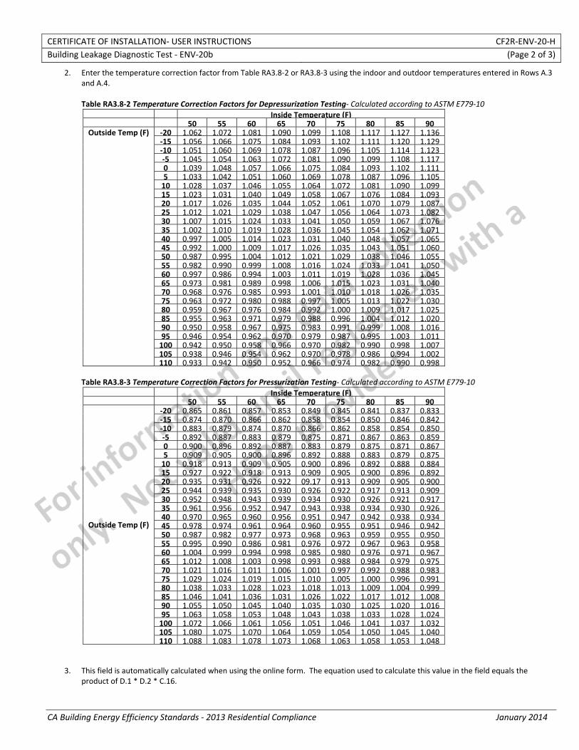
CERTIFICATE OF INSTALLATION‐ USER INSTRUCTIONS CF2R‐ENV‐20‐H Building Leakage Diagnostic Test ‐ ENV‐20b (Page 2 of 3)
CA Building Energy Efficiency Standards ‐ 2013 Residential Compliance January 2014
2. Enter the temperature correction factor from Table RA3.8‐2 or RA3.8‐3 using the indoor and outdoor temperatures entered in Rows A.3 and A.4. Table RA3.8‐2 Temperature Correction Factors for Depressurization Testing‐ Calculated according to ASTM E779‐10
Inside Temperature (F) 50 55 60 65 70 75 80 85 90
Outside Temp (F) ‐20 1.062 1.072 1.081 1.090 1.099 1.108 1.117 1.127 1.136 ‐15 1.056 1.066 1.075 1.084 1.093 1.102 1.111 1.120 1.129 ‐10 1.051 1.060 1.069 1.078 1.087 1.096 1.105 1.114 1.123 ‐5 1.045 1.054 1.063 1.072 1.081 1.090 1.099 1.108 1.117 0 1.039 1.048 1.057 1.066 1.075 1.084 1.093 1.102 1.111 5 1.033 1.042 1.051 1.060 1.069 1.078 1.087 1.096 1.105 10 1.028 1.037 1.046 1.055 1.064 1.072 1.081 1.090 1.099 15 1.023 1.031 1.040 1.049 1.058 1.067 1.076 1.084 1.093 20 1.017 1.026 1.035 1.044 1.052 1.061 1.070 1.079 1.087 25 1.012 1.021 1.029 1.038 1.047 1.056 1.064 1.073 1.082 30 1.007 1.015 1.024 1.033 1.041 1.050 1.059 1.067 1.076 35 1.002 1.010 1.019 1.028 1.036 1.045 1.054 1.062 1.071 40 0.997 1.005 1.014 1.023 1.031 1.040 1.048 1.057 1.065 45 0.992 1.000 1.009 1.017 1.026 1.035 1.043 1.051 1.060 50 0.987 0.995 1.004 1.012 1.021 1.029 1.038 1.046 1.055 55 0.982 0.990 0.999 1.008 1.016 1.024 1.033 1.041 1.050 60 0.997 0.986 0.994 1.003 1.011 1.019 1.028 1.036 1.045 65 0.973 0.981 0.989 0.998 1.006 1.015 1.023 1.031 1.040 70 0.968 0.976 0.985 0.993 1.001 1.010 1.018 1.026 1.035 75 0.963 0.972 0.980 0.988 0.997 1.005 1.013 1.022 1.030 80 0.959 0.967 0.976 0.984 0.992 1.000 1.009 1.017 1.025 85 0.955 0.963 0.971 0.979 0.988 0.996 1.004 1.012 1.020 90 0.950 0.958 0.967 0.975 0.983 0.991 0.999 1.008 1.016 95 0.946 0.954 0.962 0.970 0.979 0.987 0.995 1.003 1.011 100 0.942 0.950 0.958 0.966 0.970 0.982 0.990 0.998 1.007 105 0.938 0.946 0.954 0.962 0.970 0.978 0.986 0.994 1.002 110 0.933 0.942 0.950 0.952 0.966 0.974 0.982 0.990 0.998
Table RA3.8‐3 Temperature Correction Factors for Pressurization Testing‐ Calculated according to ASTM E779‐10
Inside Temperature (F) 50 55 60 65 70 75 80 85 90
Outside Temp (F)
‐20 0.865 0.861 0.857 0.853 0.849 0.845 0.841 0.837 0.833 ‐15 0.874 0.870 0.866 0.862 0.858 0.854 0.850 0.846 0.842 ‐10 0.883 0.879 0.874 0.870 0.866 0.862 0.858 0.854 0.850 ‐5 0.892 0.887 0.883 0.879 0.875 0.871 0.867 0.863 0.859 0 0.900 0.896 0.892 0.887 0.883 0.879 0.875 0.871 0.867 5 0.909 0.905 0.900 0.896 0.892 0.888 0.883 0.879 0.875 10 0.918 0.913 0.909 0.905 0.900 0.896 0.892 0.888 0.884 15 0.927 0.922 0.918 0.913 0.909 0.905 0.900 0.896 0.892 20 0.935 0.931 0.926 0.922 09.17 0.913 0.909 0.905 0.900 25 0.944 0.939 0.935 0.930 0.926 0.922 0.917 0.913 0.909 30 0.952 0.948 0.943 0.939 0.934 0.930 0.926 0.921 0.917 35 0.961 0.956 0.952 0.947 0.943 0.938 0.934 0.930 0.926 40 0.970 0.965 0.960 0.956 0.951 0.947 0.942 0.938 0.934 45 0.978 0.974 0.961 0.964 0.960 0.955 0.951 0.946 0.942 50 0.987 0.982 0.977 0.973 0.968 0.963 0.959 0.955 0.950 55 0.995 0.990 0.986 0.981 0.976 0.972 0.967 0.963 0.958 60 1.004 0.999 0.994 0.998 0.985 0.980 0.976 0.971 0.967 65 1.012 1.008 1.003 0.998 0.993 0.988 0.984 0.979 0.975 70 1.021 1.016 1.011 1.006 1.001 0.997 0.992 0.988 0.983 75 1.029 1.024 1.019 1.015 1.010 1.005 1.000 0.996 0.991 80 1.038 1.033 1.028 1.023 1.018 1.013 1.009 1.004 0.999 85 1.046 1.041 1.036 1.031 1.026 1.022 1.017 1.012 1.008 90 1.055 1.050 1.045 1.040 1.035 1.030 1.025 1.020 1.016 95 1.063 1.058 1.053 1.048 1.043 1.038 1.033 1.028 1.024 100 1.072 1.066 1.061 1.056 1.051 1.046 1.041 1.037 1.032 105 1.080 1.075 1.070 1.064 1.059 1.054 1.050 1.045 1.040 110 1.088 1.083 1.078 1.073 1.068 1.063 1.058 1.053 1.048
3. This field is automatically calculated when using the online form. The equation used to calculate this value in the field equals the product of D.1 * D.2 * C.16.
CERTIFICATE OF INSTALLATION‐ USER INSTRUCTIONS CF2R‐ENV‐20‐H Building Leakage Diagnostic Test ‐ ENV‐20b (Page 3 of 3)
CA Building Energy Efficiency Standards ‐ 2013 Residential Compliance January 2014
Section E. Accuracy Adjustment
1. This field is automatically calculated when using the online form. The equation used to calculate this value in the field equals: c. If the accuracy level C.8 = Standard, then enter 1 as accuracy adjustment in box E. 1 d. If the accuracy level C.8 = Reduced, accuracy adjustment equation equals 1+[0.1+(50/C. 14)]
2. This field is automatically calculated when using the online form. The equation used to calculate this value in the field equals the D.3 * E.1. = Adjusted CFM50 Note ‐ This is the number that must be less than or equal to the target building air leakage from the CF1R, shown in Row A.2.
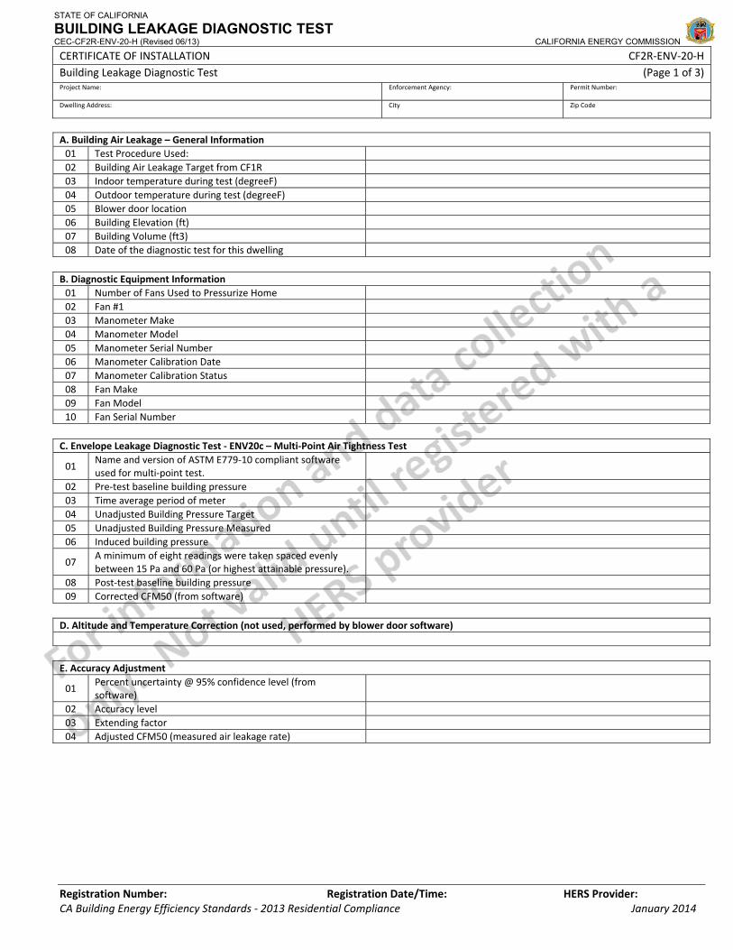
STATE OF CALIFORNIA
BUILDING LEAKAGE DIAGNOSTIC TEST CEC-CF2R-ENV-20-H (Revised 06/13) CALIFORNIA ENERGY COMMISSION
CERTIFICATE OF INSTALLATION CF2R‐ENV‐20‐H Building Leakage Diagnostic Test (Page 1 of 3) Project Name: Enforcement Agency: Permit Number:
Dwelling Address: City Zip Code
Registration Number: Registration Date/Time: HERS Provider: CA Building Energy Efficiency Standards ‐ 2013 Residential Compliance January 2014
A. Building Air Leakage – General Information 01 Test Procedure Used: 02 Building Air Leakage Target from CF1R 03 Indoor temperature during test (degreeF) 04 Outdoor temperature during test (degreeF) 05 Blower door location 06 Building Elevation (ft) 07 Building Volume (ft3) 08 Date of the diagnostic test for this dwelling B. Diagnostic Equipment Information 01 Number of Fans Used to Pressurize Home 02 Fan #1 03 Manometer Make 04 Manometer Model 05 Manometer Serial Number 06 Manometer Calibration Date 07 Manometer Calibration Status 08 Fan Make 09 Fan Model 10 Fan Serial Number C. Envelope Leakage Diagnostic Test ‐ ENV20c – Multi‐Point Air Tightness Test
01 Name and version of ASTM E779‐10 compliant software used for multi‐point test.
02 Pre‐test baseline building pressure 03 Time average period of meter 04 Unadjusted Building Pressure Target 05 Unadjusted Building Pressure Measured 06 Induced building pressure
07 A minimum of eight readings were taken spaced evenly between 15 Pa and 60 Pa (or highest attainable pressure).
08 Post‐test baseline building pressure 09 Corrected CFM50 (from software) D. Altitude and Temperature Correction (not used, performed by blower door software) E. Accuracy Adjustment
01 Percent uncertainty @ 95% confidence level (from software)
02 Accuracy level 03 Extending factor 04 Adjusted CFM50 (measured air leakage rate)
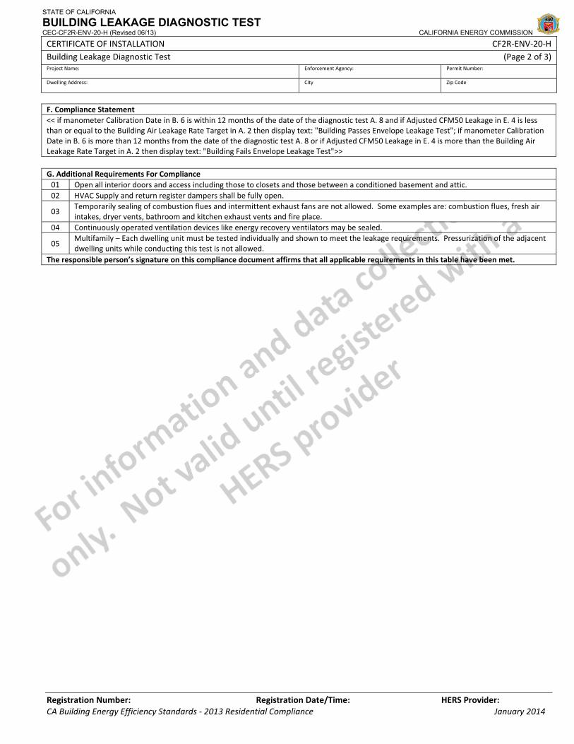
STATE OF CALIFORNIA
BUILDING LEAKAGE DIAGNOSTIC TEST CEC-CF2R-ENV-20-H (Revised 06/13) CALIFORNIA ENERGY COMMISSION
CERTIFICATE OF INSTALLATION CF2R‐ENV‐20‐H Building Leakage Diagnostic Test (Page 2 of 3) Project Name: Enforcement Agency: Permit Number:
Dwelling Address: City Zip Code
Registration Number: Registration Date/Time: HERS Provider: CA Building Energy Efficiency Standards ‐ 2013 Residential Compliance January 2014
F. Compliance Statement << if manometer Calibration Date in B. 6 is within 12 months of the date of the diagnostic test A. 8 and if Adjusted CFM50 Leakage in E. 4 is less than or equal to the Building Air Leakage Rate Target in A. 2 then display text: "Building Passes Envelope Leakage Test"; if manometer Calibration Date in B. 6 is more than 12 months from the date of the diagnostic test A. 8 or if Adjusted CFM50 Leakage in E. 4 is more than the Building Air Leakage Rate Target in A. 2 then display text: "Building Fails Envelope Leakage Test">> G. Additional Requirements For Compliance 01 Open all interior doors and access including those to closets and those between a conditioned basement and attic. 02 HVAC Supply and return register dampers shall be fully open.
03 Temporarily sealing of combustion flues and intermittent exhaust fans are not allowed. Some examples are: combustion flues, fresh air intakes, dryer vents, bathroom and kitchen exhaust vents and fire place.
04 Continuously operated ventilation devices like energy recovery ventilators may be sealed.
05 Multifamily – Each dwelling unit must be tested individually and shown to meet the leakage requirements. Pressurization of the adjacent dwelling units while conducting this test is not allowed.
The responsible person’s signature on this compliance document affirms that all applicable requirements in this table have been met.
STATE OF CALIFORNIA
BUILDING LEAKAGE DIAGNOSTIC TEST CEC-CF2R-ENV-20-H (Revised 06/13) CALIFORNIA ENERGY COMMISSION
CERTIFICATE OF INSTALLATION CF2R‐ENV‐20‐H Building Leakage Diagnostic Test (Page 3 of 3) Project Name: Enforcement Agency: Permit Number:
Dwelling Address: City Zip Code
Registration Number: Registration Date/Time: HERS Provider: CA Building Energy Efficiency Standards ‐ 2013 Residential Compliance January 2014
DOCUMENTATION AUTHOR'S DECLARATION STATEMENT1. I certify that this Certificate of Installation documentation is accurate and complete.
Documentation Author Name: Documentation Author Signature:
Documentation Author Company Name: Date Signed:
Address: CEA/HERS Certification Identification (If applicable):
City/State/Zip: Phone:
RESPONSIBLE PERSON'S DECLARATION STATEMENT
I certify the following under penalty of perjury, under the laws of the State of California:
1. The information provided on this Certificate of Installation is true and correct.
2. I am eligible under Division 3 of the Business and Professions Code in the applicable classification to accept responsibility for the system design, construction, or installation of features, materials, components, or manufactured devices for the scope of work identified on this Certificate of Installation and attest to the declarations in this statement (responsible builder/installer), otherwise I am an authorized representative of the responsible builder/installer.
3. The constructed or installed features, materials, components or manufactured devices (the installation) identified on this Certificate of Installation conforms to all applicable codes and regulations, and the installation conforms to the requirements given on the plans and specifications approved by the enforcement agency.
4. I understand that a HERS rater will check the installation to verify compliance, and that if such checking identifies defects; I am required to take corrective action at my expense. I understand that Energy Commission and HERS Provider representatives will also perform quality assurance checking of installations, including those approved as part of a sample group but not checked by a HERS rater, and if those installations fail to meet the requirements of such quality assurance checking, the required corrective action and additional checking/testing of other installations in that HERS sample group will be performed at my expense.
5. I reviewed a copy of the Certificate of Compliance approved by the enforcement agency that identifies the specific requirements for the scope of construction or installation identified on this Certificate of Installation, and I have ensured that the requirements that apply to the construction or installation have been met.
6. I will ensure that a registered copy of this Certificate of Installation shall be posted, or made available with the building permit(s) issued for the building, and made available to the enforcement agency for all applicable inspections. I understand that a registered copy of this Certificate of Installation is required to be included with the documentation the builder provides to the building owner at occupancy.
Responsible Builder/Installer Name: Responsible Builder/Installer Signature:
Company Name: (Installing Subcontractor or General Contractor or Builder/Owner) Position With Company (Title):
Address: CSLB License:
City/State/Zip: Phone Date Signed:
Third Party Quality Control Program (TPQCP) Status: Name of TPQCP (if applicable):
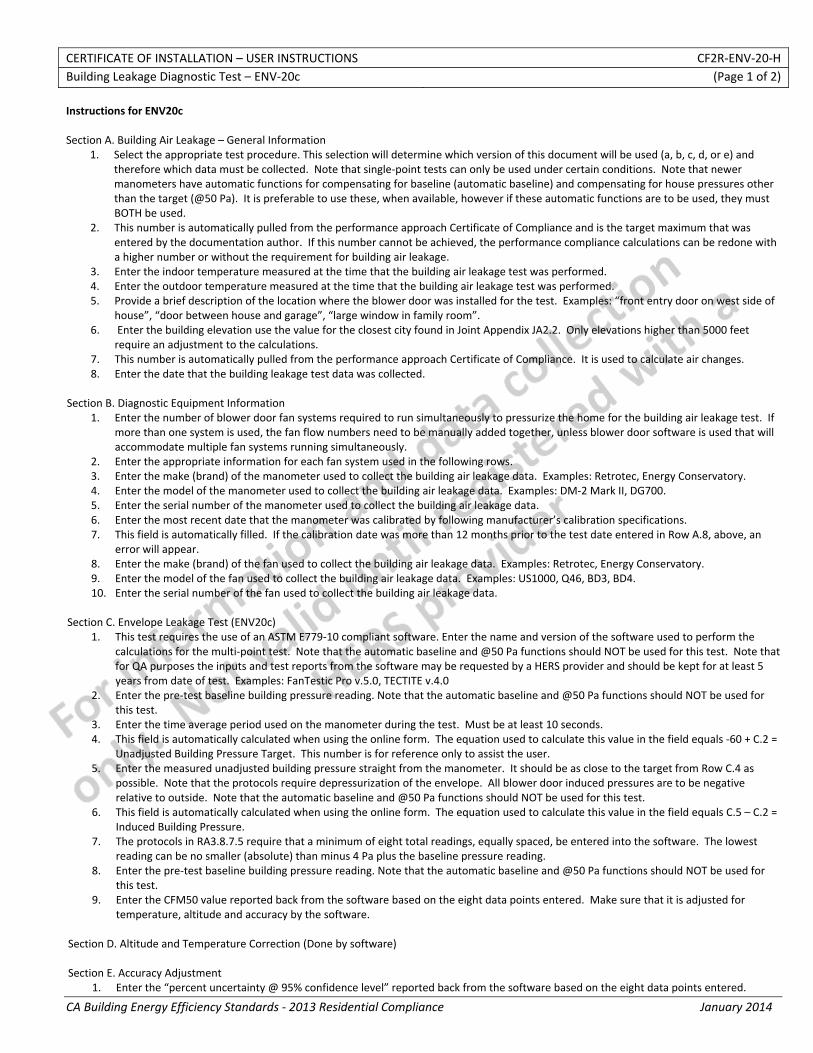
CERTIFICATE OF INSTALLATION – USER INSTRUCTIONS CF2R‐ENV‐20‐H Building Leakage Diagnostic Test – ENV‐20c (Page 1 of 2)
CA Building Energy Efficiency Standards ‐ 2013 Residential Compliance January 2014
Instructions for ENV20c Section A. Building Air Leakage – General Information
1. Select the appropriate test procedure. This selection will determine which version of this document will be used (a, b, c, d, or e) and therefore which data must be collected. Note that single‐point tests can only be used under certain conditions. Note that newer manometers have automatic functions for compensating for baseline (automatic baseline) and compensating for house pressures other than the target (@50 Pa). It is preferable to use these, when available, however if these automatic functions are to be used, they must BOTH be used.
2. This number is automatically pulled from the performance approach Certificate of Compliance and is the target maximum that was entered by the documentation author. If this number cannot be achieved, the performance compliance calculations can be redone with a higher number or without the requirement for building air leakage.
3. Enter the indoor temperature measured at the time that the building air leakage test was performed. 4. Enter the outdoor temperature measured at the time that the building air leakage test was performed. 5. Provide a brief description of the location where the blower door was installed for the test. Examples: “front entry door on west side of
house”, “door between house and garage”, “large window in family room”. 6. Enter the building elevation use the value for the closest city found in Joint Appendix JA2.2. Only elevations higher than 5000 feet
require an adjustment to the calculations. 7. This number is automatically pulled from the performance approach Certificate of Compliance. It is used to calculate air changes. 8. Enter the date that the building leakage test data was collected.
Section B. Diagnostic Equipment Information
1. Enter the number of blower door fan systems required to run simultaneously to pressurize the home for the building air leakage test. If more than one system is used, the fan flow numbers need to be manually added together, unless blower door software is used that will accommodate multiple fan systems running simultaneously.
2. Enter the appropriate information for each fan system used in the following rows. 3. Enter the make (brand) of the manometer used to collect the building air leakage data. Examples: Retrotec, Energy Conservatory. 4. Enter the model of the manometer used to collect the building air leakage data. Examples: DM‐2 Mark II, DG700. 5. Enter the serial number of the manometer used to collect the building air leakage data. 6. Enter the most recent date that the manometer was calibrated by following manufacturer’s calibration specifications. 7. This field is automatically filled. If the calibration date was more than 12 months prior to the test date entered in Row A.8, above, an
error will appear. 8. Enter the make (brand) of the fan used to collect the building air leakage data. Examples: Retrotec, Energy Conservatory. 9. Enter the model of the fan used to collect the building air leakage data. Examples: US1000, Q46, BD3, BD4. 10. Enter the serial number of the fan used to collect the building air leakage data.
Section C. Envelope Leakage Test (ENV20c) 1. This test requires the use of an ASTM E779‐10 compliant software. Enter the name and version of the software used to perform the
calculations for the multi‐point test. Note that the automatic baseline and @50 Pa functions should NOT be used for this test. Note that for QA purposes the inputs and test reports from the software may be requested by a HERS provider and should be kept for at least 5 years from date of test. Examples: FanTestic Pro v.5.0, TECTITE v.4.0
2. Enter the pre‐test baseline building pressure reading. Note that the automatic baseline and @50 Pa functions should NOT be used for this test.
3. Enter the time average period used on the manometer during the test. Must be at least 10 seconds. 4. This field is automatically calculated when using the online form. The equation used to calculate this value in the field equals ‐60 + C.2 =
Unadjusted Building Pressure Target. This number is for reference only to assist the user. 5. Enter the measured unadjusted building pressure straight from the manometer. It should be as close to the target from Row C.4 as
possible. Note that the protocols require depressurization of the envelope. All blower door induced pressures are to be negative relative to outside. Note that the automatic baseline and @50 Pa functions should NOT be used for this test.
6. This field is automatically calculated when using the online form. The equation used to calculate this value in the field equals C.5 – C.2 = Induced Building Pressure.
7. The protocols in RA3.8.7.5 require that a minimum of eight total readings, equally spaced, be entered into the software. The lowest reading can be no smaller (absolute) than minus 4 Pa plus the baseline pressure reading.
8. Enter the pre‐test baseline building pressure reading. Note that the automatic baseline and @50 Pa functions should NOT be used for this test.
9. Enter the CFM50 value reported back from the software based on the eight data points entered. Make sure that it is adjusted for temperature, altitude and accuracy by the software.
Section D. Altitude and Temperature Correction (Done by software) Section E. Accuracy Adjustment
1. Enter the “percent uncertainty @ 95% confidence level” reported back from the software based on the eight data points entered.
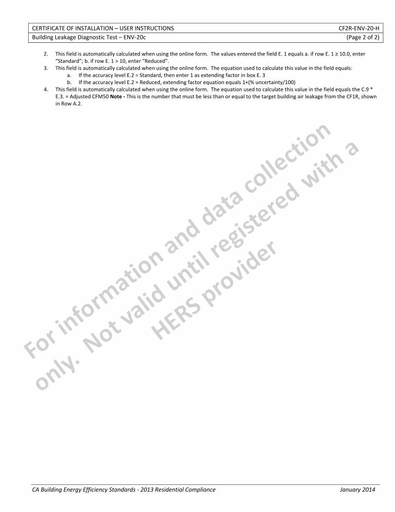
CERTIFICATE OF INSTALLATION – USER INSTRUCTIONS CF2R‐ENV‐20‐H Building Leakage Diagnostic Test – ENV‐20c (Page 2 of 2)
CA Building Energy Efficiency Standards ‐ 2013 Residential Compliance January 2014
2. This field is automatically calculated when using the online form. The values entered the field E. 1 equals a. if row E. 1 ≥ 10.0, enter “Standard”; b. if row E. 1 > 10, enter “Reduced”.
3. This field is automatically calculated when using the online form. The equation used to calculate this value in the field equals: a. If the accuracy level E.2 = Standard, then enter 1 as extending factor in box E. 3 b. If the accuracy level E.2 = Reduced, extending factor equation equals 1+(% uncertainty/100)
4. This field is automatically calculated when using the online form. The equation used to calculate this value in the field equals the C.9 * E.3. = Adjusted CFM50 Note ‐ This is the number that must be less than or equal to the target building air leakage from the CF1R, shown in Row A.2.
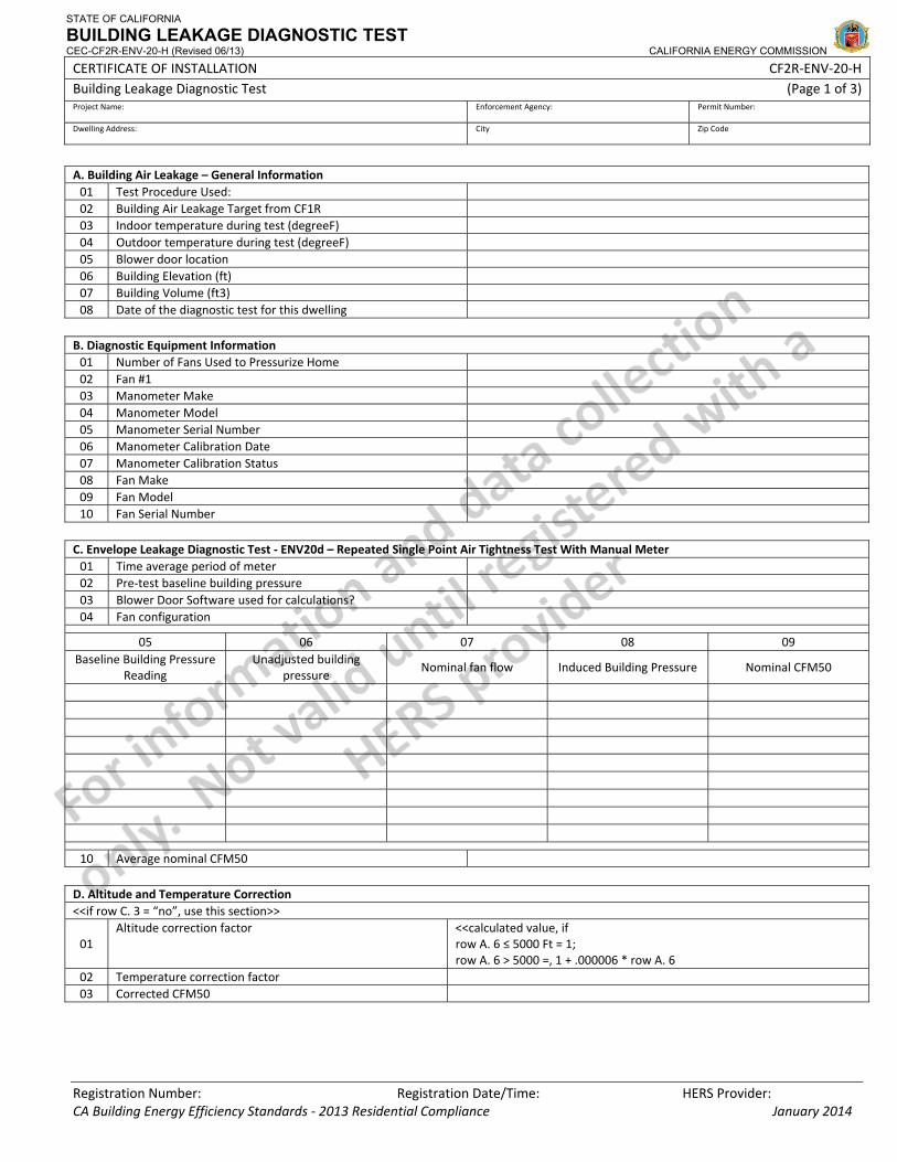
STATE OF CALIFORNIA
BUILDING LEAKAGE DIAGNOSTIC TEST CEC-CF2R-ENV-20-H (Revised 06/13) CALIFORNIA ENERGY COMMISSION
CERTIFICATE OF INSTALLATION CF2R‐ENV‐20‐H Building Leakage Diagnostic Test (Page 1 of 3) Project Name: Enforcement Agency: Permit Number:
Dwelling Address: City Zip Code
Registration Number: Registration Date/Time: HERS Provider: CA Building Energy Efficiency Standards ‐ 2013 Residential Compliance January 2014
A. Building Air Leakage – General Information 01 Test Procedure Used: 02 Building Air Leakage Target from CF1R 03 Indoor temperature during test (degreeF) 04 Outdoor temperature during test (degreeF) 05 Blower door location 06 Building Elevation (ft) 07 Building Volume (ft3) 08 Date of the diagnostic test for this dwelling B. Diagnostic Equipment Information 01 Number of Fans Used to Pressurize Home 02 Fan #1 03 Manometer Make 04 Manometer Model 05 Manometer Serial Number 06 Manometer Calibration Date 07 Manometer Calibration Status 08 Fan Make 09 Fan Model 10 Fan Serial Number C. Envelope Leakage Diagnostic Test ‐ ENV20d – Repeated Single Point Air Tightness Test With Manual Meter 01 Time average period of meter 02 Pre‐test baseline building pressure 03 Blower Door Software used for calculations? 04 Fan configuration
05 06 07 08 09 Baseline Building Pressure
Reading Unadjusted building
pressure Nominal fan flow Induced Building Pressure Nominal CFM50
10 Average nominal CFM50 D. Altitude and Temperature Correction <<if row C. 3 = “no”, use this section>>
01 Altitude correction factor <<calculated value, if
row A. 6 ≤ 5000 Ft = 1; row A. 6 > 5000 =, 1 + .000006 * row A. 6
02 Temperature correction factor 03 Corrected CFM50
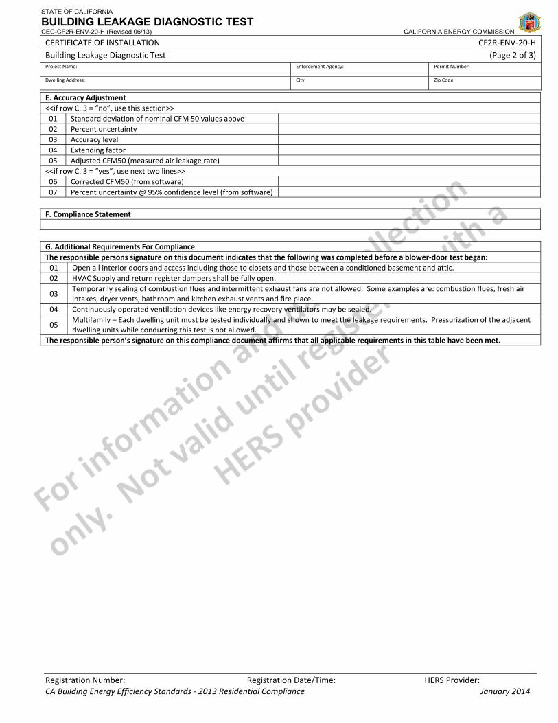
STATE OF CALIFORNIA
BUILDING LEAKAGE DIAGNOSTIC TEST CEC-CF2R-ENV-20-H (Revised 06/13) CALIFORNIA ENERGY COMMISSION
CERTIFICATE OF INSTALLATION CF2R‐ENV‐20‐H Building Leakage Diagnostic Test (Page 2 of 3) Project Name: Enforcement Agency: Permit Number:
Dwelling Address: City Zip Code
Registration Number: Registration Date/Time: HERS Provider: CA Building Energy Efficiency Standards ‐ 2013 Residential Compliance January 2014
E. Accuracy Adjustment <<if row C. 3 = “no”, use this section>> 01 Standard deviation of nominal CFM 50 values above 02 Percent uncertainty 03 Accuracy level 04 Extending factor 05 Adjusted CFM50 (measured air leakage rate) <<if row C. 3 = “yes”, use next two lines>> 06 Corrected CFM50 (from software) 07 Percent uncertainty @ 95% confidence level (from software) F. Compliance Statement G. Additional Requirements For Compliance The responsible persons signature on this document indicates that the following was completed before a blower‐door test began: 01 Open all interior doors and access including those to closets and those between a conditioned basement and attic. 02 HVAC Supply and return register dampers shall be fully open.
03 Temporarily sealing of combustion flues and intermittent exhaust fans are not allowed. Some examples are: combustion flues, fresh air intakes, dryer vents, bathroom and kitchen exhaust vents and fire place.
04 Continuously operated ventilation devices like energy recovery ventilators may be sealed.
05 Multifamily – Each dwelling unit must be tested individually and shown to meet the leakage requirements. Pressurization of the adjacent dwelling units while conducting this test is not allowed.
The responsible person’s signature on this compliance document affirms that all applicable requirements in this table have been met.

STATE OF CALIFORNIA
BUILDING LEAKAGE DIAGNOSTIC TEST CEC-CF2R-ENV-20-H (Revised 06/13) CALIFORNIA ENERGY COMMISSION
CERTIFICATE OF INSTALLATION CF2R‐ENV‐20‐H Building Leakage Diagnostic Test (Page 3 of 3) Project Name: Enforcement Agency: Permit Number:
Dwelling Address: City Zip Code
Registration Number: Registration Date/Time: HERS Provider: CA Building Energy Efficiency Standards ‐ 2013 Residential Compliance January 2014
DOCUMENTATION AUTHOR'S DECLARATION STATEMENT1. I certify that this Certificate of Installation documentation is accurate and complete.
Documentation Author Name: Documentation Author Signature:
Documentation Author Company Name: Date Signed:
Address: CEA/HERS Certification Identification (If applicable):
City/State/Zip: Phone:
RESPONSIBLE PERSON'S DECLARATION STATEMENT
I certify the following under penalty of perjury, under the laws of the State of California:
1. The information provided on this Certificate of Installation is true and correct.
2. I am eligible under Division 3 of the Business and Professions Code in the applicable classification to accept responsibility for the system design, construction, or installation of features, materials, components, or manufactured devices for the scope of work identified on this Certificate of Installation and attest to the declarations in this statement (responsible builder/installer), otherwise I am an authorized representative of the responsible builder/installer.
3. The constructed or installed features, materials, components or manufactured devices (the installation) identified on this Certificate of Installation conforms to all applicable codes and regulations, and the installation conforms to the requirements given on the plans and specifications approved by the enforcement agency.
4. I understand that a HERS rater will check the installation to verify compliance, and that if such checking identifies defects; I am required to take corrective action at my expense. I understand that Energy Commission and HERS Provider representatives will also perform quality assurance checking of installations, including those approved as part of a sample group but not checked by a HERS rater, and if those installations fail to meet the requirements of such quality assurance checking, the required corrective action and additional checking/testing of other installations in that HERS sample group will be performed at my expense.
5. I reviewed a copy of the Certificate of Compliance approved by the enforcement agency that identifies the specific requirements for the scope of construction or installation identified on this Certificate of Installation, and I have ensured that the requirements that apply to the construction or installation have been met.
6. I will ensure that a registered copy of this Certificate of Installation shall be posted, or made available with the building permit(s) issued for the building, and made available to the enforcement agency for all applicable inspections. I understand that a registered copy of this Certificate of Installation is required to be included with the documentation the builder provides to the building owner at occupancy.
Responsible Builder/Installer Name: Responsible Builder/Installer Signature:
Company Name: (Installing Subcontractor or General Contractor or Builder/Owner) Position With Company (Title):
Address: CSLB License:
City/State/Zip: Phone Date Signed:
Third Party Quality Control Program (TPQCP) Status: Name of TPQCP (if applicable):
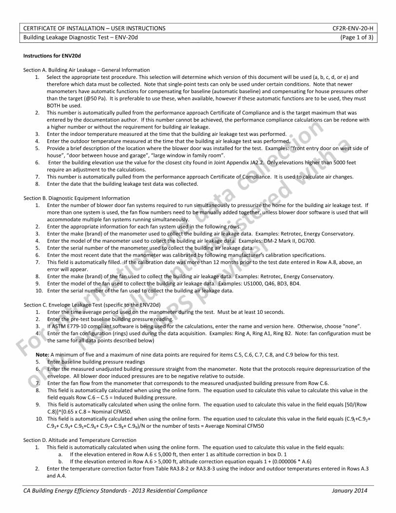
CERTIFICATE OF INSTALLATION – USER INSTRUCTIONS CF2R‐ENV‐20‐H Building Leakage Diagnostic Test – ENV‐20d (Page 1 of 3)
CA Building Energy Efficiency Standards ‐ 2013 Residential Compliance January 2014
Instructions for ENV20d Section A. Building Air Leakage – General Information
1. Select the appropriate test procedure. This selection will determine which version of this document will be used (a, b, c, d, or e) and therefore which data must be collected. Note that single‐point tests can only be used under certain conditions. Note that newer manometers have automatic functions for compensating for baseline (automatic baseline) and compensating for house pressures other than the target (@50 Pa). It is preferable to use these, when available, however if these automatic functions are to be used, they must BOTH be used.
2. This number is automatically pulled from the performance approach Certificate of Compliance and is the target maximum that was entered by the documentation author. If this number cannot be achieved, the performance compliance calculations can be redone with a higher number or without the requirement for building air leakage.
3. Enter the indoor temperature measured at the time that the building air leakage test was performed. 4. Enter the outdoor temperature measured at the time that the building air leakage test was performed. 5. Provide a brief description of the location where the blower door was installed for the test. Examples: “front entry door on west side of
house”, “door between house and garage”, “large window in family room”. 6. Enter the building elevation use the value for the closest city found in Joint Appendix JA2.2. Only elevations higher than 5000 feet
require an adjustment to the calculations. 7. This number is automatically pulled from the performance approach Certificate of Compliance. It is used to calculate air changes. 8. Enter the date that the building leakage test data was collected.
Section B. Diagnostic Equipment Information
1. Enter the number of blower door fan systems required to run simultaneously to pressurize the home for the building air leakage test. If more than one system is used, the fan flow numbers need to be manually added together, unless blower door software is used that will accommodate multiple fan systems running simultaneously.
2. Enter the appropriate information for each fan system used in the following rows. 3. Enter the make (brand) of the manometer used to collect the building air leakage data. Examples: Retrotec, Energy Conservatory. 4. Enter the model of the manometer used to collect the building air leakage data. Examples: DM‐2 Mark II, DG700. 5. Enter the serial number of the manometer used to collect the building air leakage data. 6. Enter the most recent date that the manometer was calibrated by following manufacturer’s calibration specifications. 7. This field is automatically filled. If the calibration date was more than 12 months prior to the test date entered in Row A.8, above, an
error will appear. 8. Enter the make (brand) of the fan used to collect the building air leakage data. Examples: Retrotec, Energy Conservatory. 9. Enter the model of the fan used to collect the building air leakage data. Examples: US1000, Q46, BD3, BD4. 10. Enter the serial number of the fan used to collect the building air leakage data.
Section C. Envelope Leakage Test (specific to the ENV20d) 1. Enter the time average period used on the manometer during the test. Must be at least 10 seconds. 2. Enter the pre‐test baseline building pressure reading. 3. If ASTM E779‐10 compliant software is being used for the calculations, enter the name and version here. Otherwise, choose “none”. 4. Enter the fan configuration (rings) used during the data acquisition. Examples: Ring A, Ring A1, Ring B2. Note: fan configuration must be
the same for all data points described below)
Note: A minimum of five and a maximum of nine data points are required for items C.5, C.6, C.7, C.8, and C.9 below for this test. 5. Enter baseline building pressure readings 6. Enter the measured unadjusted building pressure straight from the manometer. Note that the protocols require depressurization of the
envelope. All blower door induced pressures are to be negative relative to outside. 7. Enter the fan flow from the manometer that corresponds to the measured unadjusted building pressure from Row C.6. 8. This field is automatically calculated when using the online form. The equation used to calculate this value to calculate this value in the
field equals Row C.6 – C.5 = Induced Building pressure. 9. This field is automatically calculated when using the online form. The equation used to calculate this value in the field equals [50/(Row
C.8)]^[0.65 x C.8 = Nominal CFM50. 10. This field is automatically calculated when using the online form. The equation used to calculate this value in the field equals (C.91+C.92+
C.93+ C.94+ C.95+C.96+ C.97+ C.98+ C.99)/N or the number of tests = Average Nominal CFM50 Section D. Altitude and Temperature Correction
1. This field is automatically calculated when using the online form. The equation used to calculate this value in the field equals: a. If the elevation entered in Row A.6 ≤ 5,000 ft, then enter 1 as altitude correction in box D. 1 b. If the elevation entered in Row A.6 > 5,000 ft, altitude correction equation equals 1 + (0.000006 * A.6)
2. Enter the temperature correction factor from Table RA3.8‐2 or RA3.8‐3 using the indoor and outdoor temperatures entered in Rows A.3 and A.4.
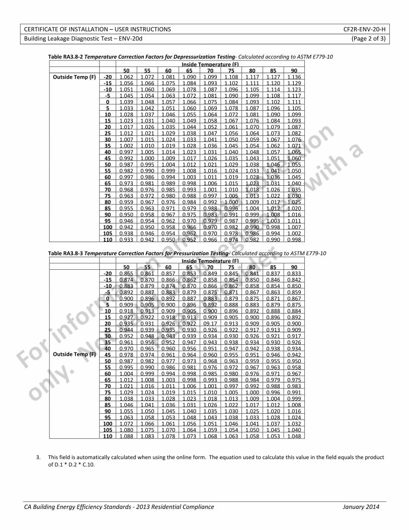
CERTIFICATE OF INSTALLATION – USER INSTRUCTIONS CF2R‐ENV‐20‐H Building Leakage Diagnostic Test – ENV‐20d (Page 2 of 3)
CA Building Energy Efficiency Standards ‐ 2013 Residential Compliance January 2014
Table RA3.8‐2 Temperature Correction Factors for Depressurization Testing‐ Calculated according to ASTM E779‐10
Inside Temperature (F) 50 55 60 65 70 75 80 85 90
Outside Temp (F) ‐20 1.062 1.072 1.081 1.090 1.099 1.108 1.117 1.127 1.136 ‐15 1.056 1.066 1.075 1.084 1.093 1.102 1.111 1.120 1.129 ‐10 1.051 1.060 1.069 1.078 1.087 1.096 1.105 1.114 1.123 ‐5 1.045 1.054 1.063 1.072 1.081 1.090 1.099 1.108 1.117 0 1.039 1.048 1.057 1.066 1.075 1.084 1.093 1.102 1.111 5 1.033 1.042 1.051 1.060 1.069 1.078 1.087 1.096 1.105 10 1.028 1.037 1.046 1.055 1.064 1.072 1.081 1.090 1.099 15 1.023 1.031 1.040 1.049 1.058 1.067 1.076 1.084 1.093 20 1.017 1.026 1.035 1.044 1.052 1.061 1.070 1.079 1.087 25 1.012 1.021 1.029 1.038 1.047 1.056 1.064 1.073 1.082 30 1.007 1.015 1.024 1.033 1.041 1.050 1.059 1.067 1.076 35 1.002 1.010 1.019 1.028 1.036 1.045 1.054 1.062 1.071 40 0.997 1.005 1.014 1.023 1.031 1.040 1.048 1.057 1.065 45 0.992 1.000 1.009 1.017 1.026 1.035 1.043 1.051 1.060 50 0.987 0.995 1.004 1.012 1.021 1.029 1.038 1.046 1.055 55 0.982 0.990 0.999 1.008 1.016 1.024 1.033 1.041 1.050 60 0.997 0.986 0.994 1.003 1.011 1.019 1.028 1.036 1.045 65 0.973 0.981 0.989 0.998 1.006 1.015 1.023 1.031 1.040 70 0.968 0.976 0.985 0.993 1.001 1.010 1.018 1.026 1.035 75 0.963 0.972 0.980 0.988 0.997 1.005 1.013 1.022 1.030 80 0.959 0.967 0.976 0.984 0.992 1.000 1.009 1.017 1.025 85 0.955 0.963 0.971 0.979 0.988 0.996 1.004 1.012 1.020 90 0.950 0.958 0.967 0.975 0.983 0.991 0.999 1.008 1.016 95 0.946 0.954 0.962 0.970 0.979 0.987 0.995 1.003 1.011 100 0.942 0.950 0.958 0.966 0.970 0.982 0.990 0.998 1.007 105 0.938 0.946 0.954 0.962 0.970 0.978 0.986 0.994 1.002 110 0.933 0.942 0.950 0.952 0.966 0.974 0.982 0.990 0.998
Table RA3.8‐3 Temperature Correction Factors for Pressurization Testing‐ Calculated according to ASTM E779‐10
Inside Temperature (F) 50 55 60 65 70 75 80 85 90
Outside Temp (F)
‐20 0.865 0.861 0.857 0.853 0.849 0.845 0.841 0.837 0.833 ‐15 0.874 0.870 0.866 0.862 0.858 0.854 0.850 0.846 0.842 ‐10 0.883 0.879 0.874 0.870 0.866 0.862 0.858 0.854 0.850 ‐5 0.892 0.887 0.883 0.879 0.875 0.871 0.867 0.863 0.859 0 0.900 0.896 0.892 0.887 0.883 0.879 0.875 0.871 0.867 5 0.909 0.905 0.900 0.896 0.892 0.888 0.883 0.879 0.875 10 0.918 0.913 0.909 0.905 0.900 0.896 0.892 0.888 0.884 15 0.927 0.922 0.918 0.913 0.909 0.905 0.900 0.896 0.892 20 0.935 0.931 0.926 0.922 09.17 0.913 0.909 0.905 0.900 25 0.944 0.939 0.935 0.930 0.926 0.922 0.917 0.913 0.909 30 0.952 0.948 0.943 0.939 0.934 0.930 0.926 0.921 0.917 35 0.961 0.956 0.952 0.947 0.943 0.938 0.934 0.930 0.926 40 0.970 0.965 0.960 0.956 0.951 0.947 0.942 0.938 0.934 45 0.978 0.974 0.961 0.964 0.960 0.955 0.951 0.946 0.942 50 0.987 0.982 0.977 0.973 0.968 0.963 0.959 0.955 0.950 55 0.995 0.990 0.986 0.981 0.976 0.972 0.967 0.963 0.958 60 1.004 0.999 0.994 0.998 0.985 0.980 0.976 0.971 0.967 65 1.012 1.008 1.003 0.998 0.993 0.988 0.984 0.979 0.975 70 1.021 1.016 1.011 1.006 1.001 0.997 0.992 0.988 0.983 75 1.029 1.024 1.019 1.015 1.010 1.005 1.000 0.996 0.991 80 1.038 1.033 1.028 1.023 1.018 1.013 1.009 1.004 0.999 85 1.046 1.041 1.036 1.031 1.026 1.022 1.017 1.012 1.008 90 1.055 1.050 1.045 1.040 1.035 1.030 1.025 1.020 1.016 95 1.063 1.058 1.053 1.048 1.043 1.038 1.033 1.028 1.024 100 1.072 1.066 1.061 1.056 1.051 1.046 1.041 1.037 1.032 105 1.080 1.075 1.070 1.064 1.059 1.054 1.050 1.045 1.040 110 1.088 1.083 1.078 1.073 1.068 1.063 1.058 1.053 1.048
3. This field is automatically calculated when using the online form. The equation used to calculate this value in the field equals the product of D.1 * D.2 * C.10.
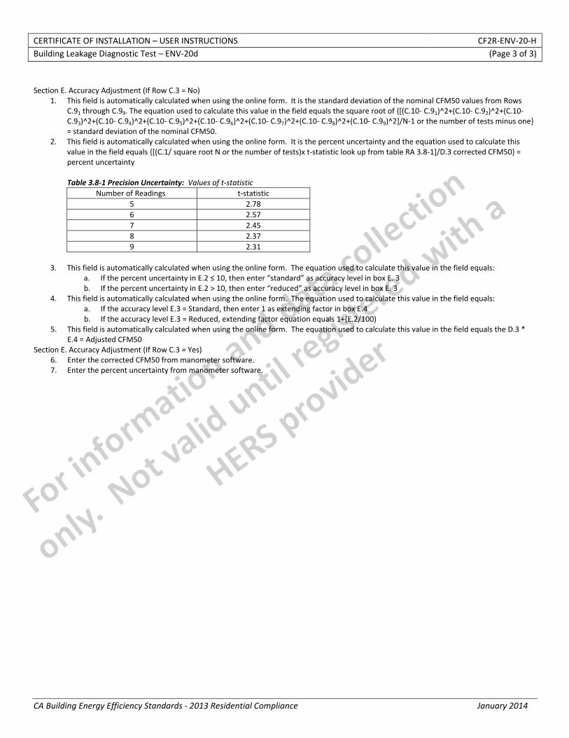
CERTIFICATE OF INSTALLATION – USER INSTRUCTIONS CF2R‐ENV‐20‐H Building Leakage Diagnostic Test – ENV‐20d (Page 3 of 3)
CA Building Energy Efficiency Standards ‐ 2013 Residential Compliance January 2014
Section E. Accuracy Adjustment (If Row C.3 = No)
1. This field is automatically calculated when using the online form. It is the standard deviation of the nominal CFM50 values from Rows C.91 through C.99. The equation used to calculate this value in the field equals the square root of {[(C.10‐ C.91)^2+(C.10‐ C.92)^2+(C.10‐ C.93)^2+(C.10‐ C.94)^2+(C.10‐ C.95)^2+(C.10‐ C.96)^2+(C.10‐ C.97)^2+(C.10‐ C.98)^2+(C.10‐ C.99)^2]/N‐1 or the number of tests minus one} = standard deviation of the nominal CFM50.
2. This field is automatically calculated when using the online form. It is the percent uncertainty and the equation used to calculate this value in the field equals {[(C.1/ square root N or the number of tests)x t‐statistic look up from table RA 3.8‐1]/D.3 corrected CFM50} = percent uncertainty Table 3.8‐1 Precision Uncertainty: Values of t‐statistic
Number of Readings t‐statistic 5 2.78 6 2.57 7 2.45 8 2.37 9 2.31
3. This field is automatically calculated when using the online form. The equation used to calculate this value in the field equals:
a. If the percent uncertainty in E.2 ≤ 10, then enter “standard” as accuracy level in box E. 3 b. If the percent uncertainty in E.2 > 10, then enter “reduced” as accuracy level in box E. 3
4. This field is automatically calculated when using the online form. The equation used to calculate this value in the field equals: a. If the accuracy level E.3 = Standard, then enter 1 as extending factor in box E.4 b. If the accuracy level E.3 = Reduced, extending factor equation equals 1+(E.2/100)
5. This field is automatically calculated when using the online form. The equation used to calculate this value in the field equals the D.3 * E.4 = Adjusted CFM50
Section E. Accuracy Adjustment (If Row C.3 = Yes) 6. Enter the corrected CFM50 from manometer software. 7. Enter the percent uncertainty from manometer software.

STATE OF CALIFORNIA
BUILDING LEAKAGE DIAGNOSTIC TEST CEC-CF2R-ENV-20-H (Revised 06/13) CALIFORNIA ENERGY COMMISSION
CERTIFICATE OF INSTALLATION CF2R‐ENV‐20‐H Building Leakage Diagnostic Test (Page 1 of 4) Project Name: Enforcement Agency: Permit Number:
Dwelling Address: City Zip Code
Registration Number: Registration Date/Time: HERS Provider: CA Building Energy Efficiency Standards ‐ 2013 Residential Compliance January 2014
A. Building Air Leakage – General Information
01 Test Procedure Used:
02 Building Air Leakage Target from CF1R
03 Indoor temperature during test (degreeF)
04 Outdoor temperature during test (degreeF)
05 Blower door location
06 Building Elevation (ft)
07 Building Volume (ft3)
08 Date of the diagnostic test for this dwelling
B. Diagnostic Equipment Information
01 Number of Fans Used to Pressurize Home
02 Fan #1
03 Manometer Make
04 Manometer Model
05 Manometer Serial Number
06 Manometer Calibration Date
07 Manometer Calibration Status
08 Fan Make
09 Fan Model
10 Fan Serial Number
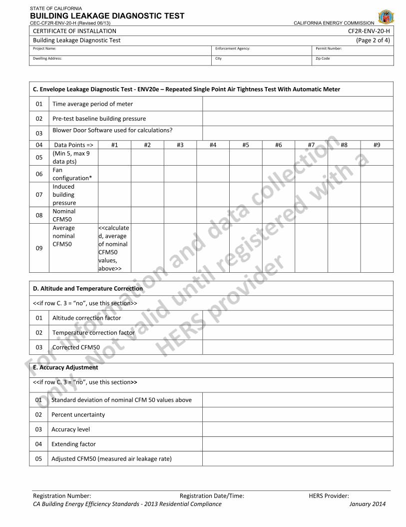
STATE OF CALIFORNIA
BUILDING LEAKAGE DIAGNOSTIC TEST CEC-CF2R-ENV-20-H (Revised 06/13) CALIFORNIA ENERGY COMMISSION
CERTIFICATE OF INSTALLATION CF2R‐ENV‐20‐H Building Leakage Diagnostic Test (Page 2 of 4) Project Name: Enforcement Agency: Permit Number:
Dwelling Address: City Zip Code
Registration Number: Registration Date/Time: HERS Provider: CA Building Energy Efficiency Standards ‐ 2013 Residential Compliance January 2014
C. Envelope Leakage Diagnostic Test ‐ ENV20e – Repeated Single Point Air Tightness Test With Automatic Meter
01 Time average period of meter
02 Pre‐test baseline building pressure
03 Blower Door Software used for calculations?
04 Data Points => #1 #2 #3 #4 #5 #6 #7 #8 #9
05 (Min 5, max 9 data pts)
06 Fan configuration*
07 Induced building pressure
08 Nominal CFM50
09
Average nominal CFM50
<<calculated, average of nominal CFM50 values, above>>
D. Altitude and Temperature Correction
<<if row C. 3 = “no”, use this section>>
01 Altitude correction factor
02 Temperature correction factor
03 Corrected CFM50
E. Accuracy Adjustment
<<if row C. 3 = “no”, use this section>>
01 Standard deviation of nominal CFM 50 values above
02 Percent uncertainty
03 Accuracy level
04 Extending factor
05 Adjusted CFM50 (measured air leakage rate)

STATE OF CALIFORNIA
BUILDING LEAKAGE DIAGNOSTIC TEST CEC-CF2R-ENV-20-H (Revised 06/13) CALIFORNIA ENERGY COMMISSION
CERTIFICATE OF INSTALLATION CF2R‐ENV‐20‐H Building Leakage Diagnostic Test (Page 3 of 4) Project Name: Enforcement Agency: Permit Number:
Dwelling Address: City Zip Code
Registration Number: Registration Date/Time: HERS Provider: CA Building Energy Efficiency Standards ‐ 2013 Residential Compliance January 2014
<<if row C. 3 = “yes”, use next two lines>>
06 Corrected CFM50 (from software)
07 Percent uncertainty @ 95% confidence level (fromsoftware)
F. Compliance Statement G. Additional Requirements For Compliance The responsible persons signature on this document indicates that the following was completed before a blower‐door test began: 01 Open all interior doors and access including those to closets and those between a conditioned basement and attic.02 HVAC Supply and return register dampers shall be fully open.
03 Temporarily sealing of combustion flues and intermittent exhaust fans are not allowed. Some examples are: combustion flues, fresh air intakes, dryer vents, bathroom and kitchen exhaust vents and fire place.
04 Continuously operated ventilation devices like energy recovery ventilators may be sealed.
05 Multifamily – Each dwelling unit must be tested individually and shown to meet the leakage requirements. Pressurization of the adjacent dwelling units while conducting this test is not allowed.
The responsible person’s signature on this compliance document affirms that all applicable requirements in this table have been met.

STATE OF CALIFORNIA
BUILDING LEAKAGE DIAGNOSTIC TEST CEC-CF2R-ENV-20-H (Revised 06/13) CALIFORNIA ENERGY COMMISSION
CERTIFICATE OF INSTALLATION CF2R‐ENV‐20‐H Building Leakage Diagnostic Test (Page 4 of 4) Project Name: Enforcement Agency: Permit Number:
Dwelling Address: City Zip Code
Registration Number: Registration Date/Time: HERS Provider: CA Building Energy Efficiency Standards ‐ 2013 Residential Compliance January 2014
DOCUMENTATION AUTHOR'S DECLARATION STATEMENT1. I certify that this Certificate of Installation documentation is accurate and complete.
Documentation Author Name: Documentation Author Signature:
Documentation Author Company Name: Date Signed:
Address: CEA/HERS Certification Identification (If applicable):
City/State/Zip: Phone:
RESPONSIBLE PERSON'S DECLARATION STATEMENT
I certify the following under penalty of perjury, under the laws of the State of California:
1. The information provided on this Certificate of Installation is true and correct.
2. I am eligible under Division 3 of the Business and Professions Code in the applicable classification to accept responsibility for the system design, construction, or installation of features, materials, components, or manufactured devices for the scope of work identified on this Certificate of Installation and attest to the declarations in this statement (responsible builder/installer), otherwise I am an authorized representative of the responsible builder/installer.
3. The constructed or installed features, materials, components or manufactured devices (the installation) identified on this Certificate of Installation conforms to all applicable codes and regulations, and the installation conforms to the requirements given on the plans and specifications approved by the enforcement agency.
4. I understand that a HERS rater will check the installation to verify compliance, and that if such checking identifies defects; I am required to take corrective action at my expense. I understand that Energy Commission and HERS Provider representatives will also perform quality assurance checking of installations, including those approved as part of a sample group but not checked by a HERS rater, and if those installations fail to meet the requirements of such quality assurance checking, the required corrective action and additional checking/testing of other installations in that HERS sample group will be performed at my expense.
5. I reviewed a copy of the Certificate of Compliance approved by the enforcement agency that identifies the specific requirements for the scope of construction or installation identified on this Certificate of Installation, and I have ensured that the requirements that apply to the construction or installation have been met.
6. I will ensure that a registered copy of this Certificate of Installation shall be posted, or made available with the building permit(s) issued for the building, and made available to the enforcement agency for all applicable inspections. I understand that a registered copy of this Certificate of Installation is required to be included with the documentation the builder provides to the building owner at occupancy.
Responsible Builder/Installer Name: Responsible Builder/Installer Signature:
Company Name: (Installing Subcontractor or General Contractor or Builder/Owner) Position With Company (Title):
Address: CSLB License:
City/State/Zip: Phone Date Signed:
Third Party Quality Control Program (TPQCP) Status: Name of TPQCP (if applicable):
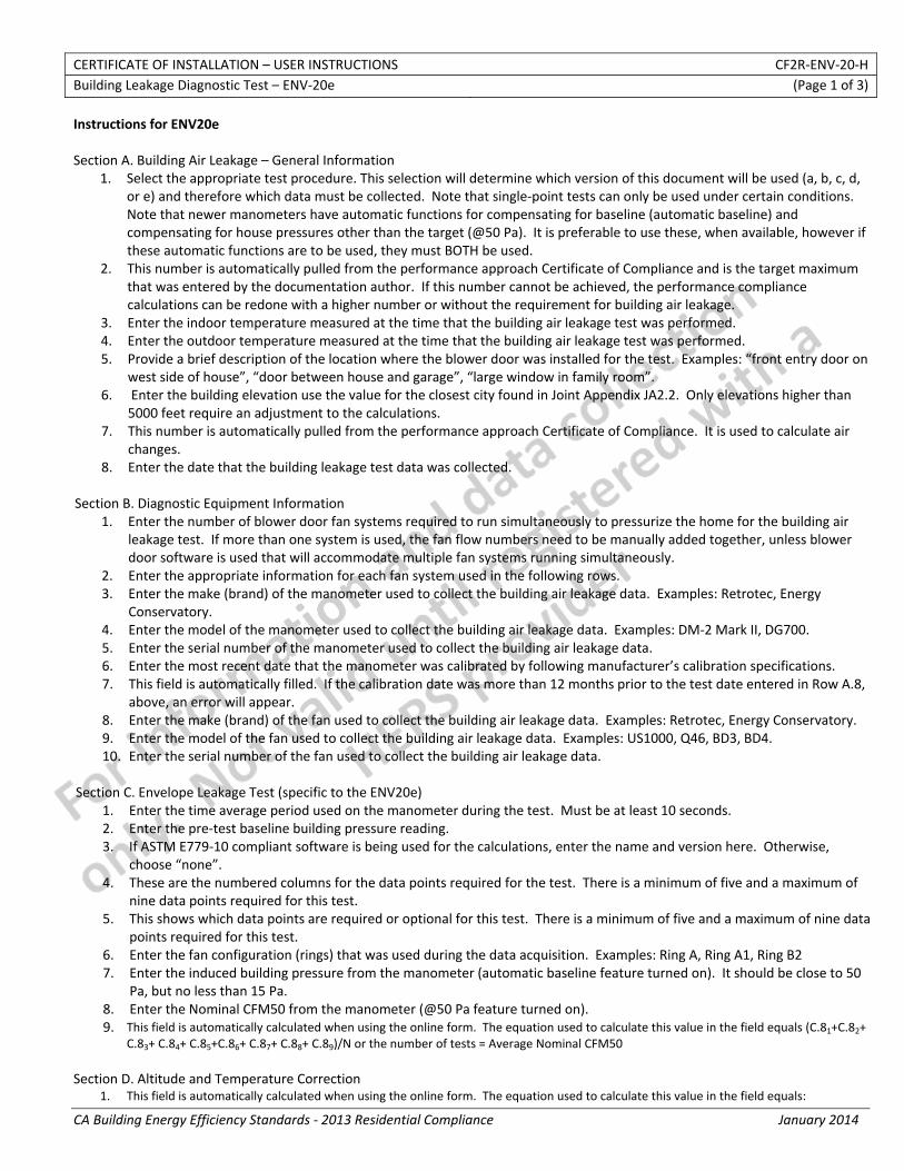
CERTIFICATE OF INSTALLATION – USER INSTRUCTIONS CF2R‐ENV‐20‐H Building Leakage Diagnostic Test – ENV‐20e (Page 1 of 3)
CA Building Energy Efficiency Standards ‐ 2013 Residential Compliance January 2014
Instructions for ENV20e Section A. Building Air Leakage – General Information
1. Select the appropriate test procedure. This selection will determine which version of this document will be used (a, b, c, d, or e) and therefore which data must be collected. Note that single‐point tests can only be used under certain conditions. Note that newer manometers have automatic functions for compensating for baseline (automatic baseline) and compensating for house pressures other than the target (@50 Pa). It is preferable to use these, when available, however if these automatic functions are to be used, they must BOTH be used.
2. This number is automatically pulled from the performance approach Certificate of Compliance and is the target maximum that was entered by the documentation author. If this number cannot be achieved, the performance compliance calculations can be redone with a higher number or without the requirement for building air leakage.
3. Enter the indoor temperature measured at the time that the building air leakage test was performed. 4. Enter the outdoor temperature measured at the time that the building air leakage test was performed. 5. Provide a brief description of the location where the blower door was installed for the test. Examples: “front entry door on
west side of house”, “door between house and garage”, “large window in family room”. 6. Enter the building elevation use the value for the closest city found in Joint Appendix JA2.2. Only elevations higher than
5000 feet require an adjustment to the calculations. 7. This number is automatically pulled from the performance approach Certificate of Compliance. It is used to calculate air
changes. 8. Enter the date that the building leakage test data was collected.
Section B. Diagnostic Equipment Information
1. Enter the number of blower door fan systems required to run simultaneously to pressurize the home for the building air leakage test. If more than one system is used, the fan flow numbers need to be manually added together, unless blower door software is used that will accommodate multiple fan systems running simultaneously.
2. Enter the appropriate information for each fan system used in the following rows. 3. Enter the make (brand) of the manometer used to collect the building air leakage data. Examples: Retrotec, Energy
Conservatory. 4. Enter the model of the manometer used to collect the building air leakage data. Examples: DM‐2 Mark II, DG700. 5. Enter the serial number of the manometer used to collect the building air leakage data. 6. Enter the most recent date that the manometer was calibrated by following manufacturer’s calibration specifications. 7. This field is automatically filled. If the calibration date was more than 12 months prior to the test date entered in Row A.8,
above, an error will appear. 8. Enter the make (brand) of the fan used to collect the building air leakage data. Examples: Retrotec, Energy Conservatory. 9. Enter the model of the fan used to collect the building air leakage data. Examples: US1000, Q46, BD3, BD4. 10. Enter the serial number of the fan used to collect the building air leakage data.
Section C. Envelope Leakage Test (specific to the ENV20e)
1. Enter the time average period used on the manometer during the test. Must be at least 10 seconds. 2. Enter the pre‐test baseline building pressure reading. 3. If ASTM E779‐10 compliant software is being used for the calculations, enter the name and version here. Otherwise,
choose “none”. 4. These are the numbered columns for the data points required for the test. There is a minimum of five and a maximum of
nine data points required for this test. 5. This shows which data points are required or optional for this test. There is a minimum of five and a maximum of nine data
points required for this test. 6. Enter the fan configuration (rings) that was used during the data acquisition. Examples: Ring A, Ring A1, Ring B2 7. Enter the induced building pressure from the manometer (automatic baseline feature turned on). It should be close to 50
Pa, but no less than 15 Pa. 8. Enter the Nominal CFM50 from the manometer (@50 Pa feature turned on). 9. This field is automatically calculated when using the online form. The equation used to calculate this value in the field equals (C.81+C.82+
C.83+ C.84+ C.85+C.86+ C.87+ C.88+ C.89)/N or the number of tests = Average Nominal CFM50 Section D. Altitude and Temperature Correction
1. This field is automatically calculated when using the online form. The equation used to calculate this value in the field equals:

CERTIFICATE OF INSTALLATION – USER INSTRUCTIONS CF2R‐ENV‐20‐H Building Leakage Diagnostic Test – ENV‐20e (Page 2 of 3)
CA Building Energy Efficiency Standards ‐ 2013 Residential Compliance January 2014
a. If the elevation entered in Row A.6 ≤ 5,000 ft, then enter 1 as altitude correction in box D. 1 b. If the elevation entered in Row A.6 > 5,000 ft, altitude correction equation equals 1 + (0.000006 * A.6)
2. Enter the temperature correction factor from Table RA3.8‐2 or RA3.8‐3 using the indoor and outdoor temperatures entered in Rows A.3 and A.4. Table RA3.8‐2 Temperature Correction Factors for Depressurization Testing‐ Calculated according to ASTM E779‐10
Inside Temperature (F) 50 55 60 65 70 75 80 85 90
Outside Temp (F) ‐20 1.062 1.072 1.081 1.090 1.099 1.108 1.117 1.127 1.136 ‐15 1.056 1.066 1.075 1.084 1.093 1.102 1.111 1.120 1.129 ‐10 1.051 1.060 1.069 1.078 1.087 1.096 1.105 1.114 1.123 ‐5 1.045 1.054 1.063 1.072 1.081 1.090 1.099 1.108 1.117 0 1.039 1.048 1.057 1.066 1.075 1.084 1.093 1.102 1.111 5 1.033 1.042 1.051 1.060 1.069 1.078 1.087 1.096 1.105 10 1.028 1.037 1.046 1.055 1.064 1.072 1.081 1.090 1.099 15 1.023 1.031 1.040 1.049 1.058 1.067 1.076 1.084 1.093 20 1.017 1.026 1.035 1.044 1.052 1.061 1.070 1.079 1.087 25 1.012 1.021 1.029 1.038 1.047 1.056 1.064 1.073 1.082 30 1.007 1.015 1.024 1.033 1.041 1.050 1.059 1.067 1.076 35 1.002 1.010 1.019 1.028 1.036 1.045 1.054 1.062 1.071 40 0.997 1.005 1.014 1.023 1.031 1.040 1.048 1.057 1.065 45 0.992 1.000 1.009 1.017 1.026 1.035 1.043 1.051 1.060 50 0.987 0.995 1.004 1.012 1.021 1.029 1.038 1.046 1.055 55 0.982 0.990 0.999 1.008 1.016 1.024 1.033 1.041 1.050 60 0.997 0.986 0.994 1.003 1.011 1.019 1.028 1.036 1.045 65 0.973 0.981 0.989 0.998 1.006 1.015 1.023 1.031 1.040 70 0.968 0.976 0.985 0.993 1.001 1.010 1.018 1.026 1.035 75 0.963 0.972 0.980 0.988 0.997 1.005 1.013 1.022 1.030 80 0.959 0.967 0.976 0.984 0.992 1.000 1.009 1.017 1.025 85 0.955 0.963 0.971 0.979 0.988 0.996 1.004 1.012 1.020 90 0.950 0.958 0.967 0.975 0.983 0.991 0.999 1.008 1.016 95 0.946 0.954 0.962 0.970 0.979 0.987 0.995 1.003 1.011 100 0.942 0.950 0.958 0.966 0.970 0.982 0.990 0.998 1.007 105 0.938 0.946 0.954 0.962 0.970 0.978 0.986 0.994 1.002 110 0.933 0.942 0.950 0.952 0.966 0.974 0.982 0.990 0.998
Table RA3.8‐3 Temperature Correction Factors for Pressurization Testing‐ Calculated according to ASTM E779‐10
Inside Temperature (F) 50 55 60 65 70 75 80 85 90
Outside Temp (F)
‐20 0.865 0.861 0.857 0.853 0.849 0.845 0.841 0.837 0.833 ‐15 0.874 0.870 0.866 0.862 0.858 0.854 0.850 0.846 0.842 ‐10 0.883 0.879 0.874 0.870 0.866 0.862 0.858 0.854 0.850 ‐5 0.892 0.887 0.883 0.879 0.875 0.871 0.867 0.863 0.859 0 0.900 0.896 0.892 0.887 0.883 0.879 0.875 0.871 0.867 5 0.909 0.905 0.900 0.896 0.892 0.888 0.883 0.879 0.875 10 0.918 0.913 0.909 0.905 0.900 0.896 0.892 0.888 0.884 15 0.927 0.922 0.918 0.913 0.909 0.905 0.900 0.896 0.892 20 0.935 0.931 0.926 0.922 09.17 0.913 0.909 0.905 0.900 25 0.944 0.939 0.935 0.930 0.926 0.922 0.917 0.913 0.909 30 0.952 0.948 0.943 0.939 0.934 0.930 0.926 0.921 0.917 35 0.961 0.956 0.952 0.947 0.943 0.938 0.934 0.930 0.926 40 0.970 0.965 0.960 0.956 0.951 0.947 0.942 0.938 0.934 45 0.978 0.974 0.961 0.964 0.960 0.955 0.951 0.946 0.942 50 0.987 0.982 0.977 0.973 0.968 0.963 0.959 0.955 0.950 55 0.995 0.990 0.986 0.981 0.976 0.972 0.967 0.963 0.958 60 1.004 0.999 0.994 0.998 0.985 0.980 0.976 0.971 0.967 65 1.012 1.008 1.003 0.998 0.993 0.988 0.984 0.979 0.975 70 1.021 1.016 1.011 1.006 1.001 0.997 0.992 0.988 0.983 75 1.029 1.024 1.019 1.015 1.010 1.005 1.000 0.996 0.991 80 1.038 1.033 1.028 1.023 1.018 1.013 1.009 1.004 0.999 85 1.046 1.041 1.036 1.031 1.026 1.022 1.017 1.012 1.008 90 1.055 1.050 1.045 1.040 1.035 1.030 1.025 1.020 1.016 95 1.063 1.058 1.053 1.048 1.043 1.038 1.033 1.028 1.024 100 1.072 1.066 1.061 1.056 1.051 1.046 1.041 1.037 1.032 105 1.080 1.075 1.070 1.064 1.059 1.054 1.050 1.045 1.040 110 1.088 1.083 1.078 1.073 1.068 1.063 1.058 1.053 1.048
3. This field is automatically calculated when using the online form. The equation used to calculate this value in the field equals the
product of D.1 * D.2 * C.9.

CERTIFICATE OF INSTALLATION – USER INSTRUCTIONS CF2R‐ENV‐20‐H Building Leakage Diagnostic Test – ENV‐20e (Page 3 of 3)
CA Building Energy Efficiency Standards ‐ 2013 Residential Compliance January 2014
Section E. Accuracy Adjustment (If Row C.3 = No) 1. This field is automatically calculated when using the online form. It is the standard deviation of the nominal CFM50 values from Rows
C.91 through C.99. The equation used to calculate this value in the field equals the square root of {[(C.10‐ C.91)^2+(C.10‐ C.92)^2+(C.10‐ C.93)^2+(C.10‐ C.94)^2+(C.10‐ C.95)^2+(C.10‐ C.96)^2+(C.10‐ C.97)^2+(C.10‐ C.98)^2+(C.10‐ C.99)^2]/N‐1 or the number of tests minus one} = standard deviation of the nominal CFM50.
2. This field is automatically calculated when using the online form. It is the percent uncertainty and the equation used to calculate this value in the field equals {[(C.1/ square root N or the number of tests)x t‐statistic look up from table RA 3.8‐1]/D.3 corrected CFM50} = percent uncertainty Table 3.8‐1 Precision Uncertainty: Values of t‐statistic
Number of Readings t‐statistic 5 2.78 6 2.57 7 2.45 8 2.37 9 2.31
3. This field is automatically calculated when using the online form. The equation used to calculate this value in the field equals:
a. If the percent uncertainty in E.2 ≤ 10, then enter “standard” as accuracy level in box E. 3 b. If the percent uncertainty in E.2 > 10, then enter “reduced” as accuracy level in box E. 3
4. This field is automatically calculated when using the online form. The equation used to calculate this value in the field equals: a. If the accuracy level E.3 = Standard, then enter 1 as extending factor in box E.4 b. If the accuracy level E.3 = Reduced, extending factor equation equals 1+(E.2/100)
5. This field is automatically calculated when using the online form. The equation used to calculate this value in the field equals the D.3 * E.4 = Adjusted CFM50
Section E. Accuracy Adjustment (If Row C.3 = Yes) 6. Enter the corrected CFM50 from manometer software. 7. Enter the percent uncertainty from manometer software.
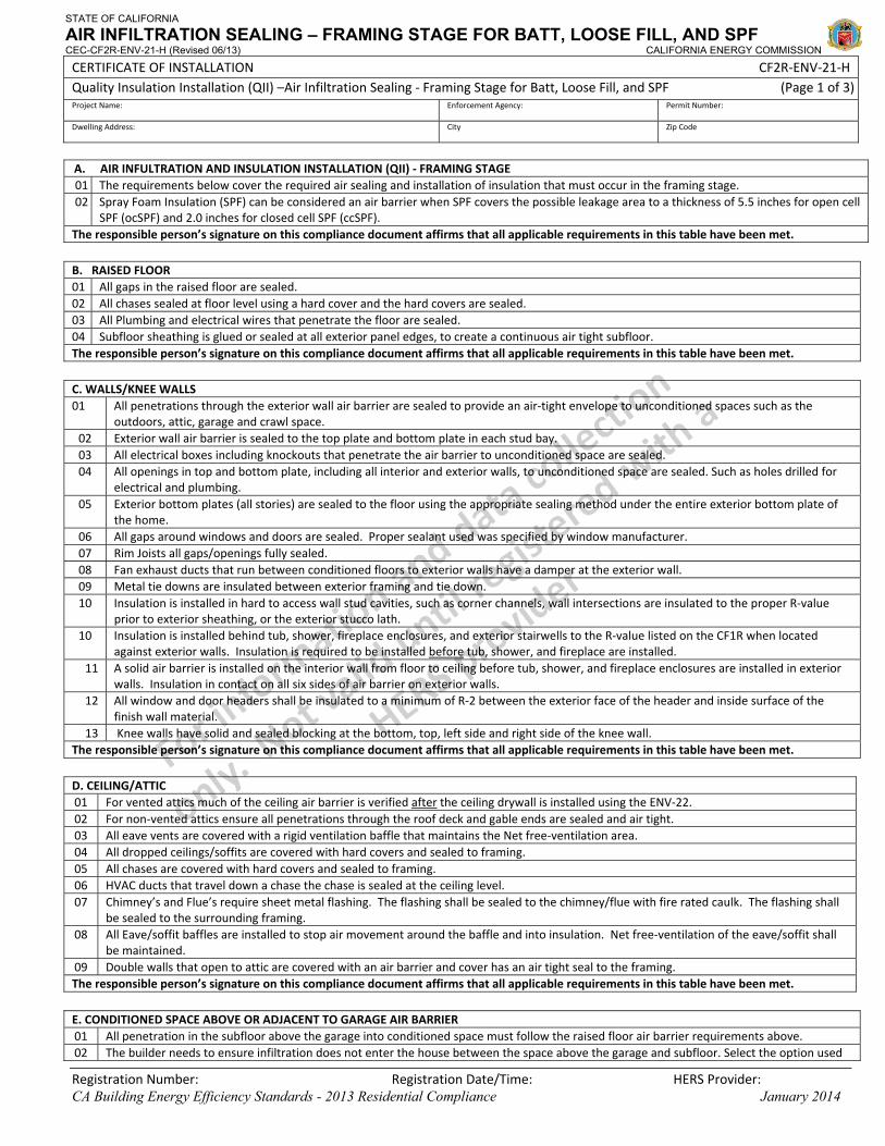
STATE OF CALIFORNIA
AIR INFILTRATION SEALING – FRAMING STAGE FOR BATT, LOOSE FILL, AND SPF CEC-CF2R-ENV-21-H (Revised 06/13) CALIFORNIA ENERGY COMMISSION
CERTIFICATE OF INSTALLATION CF2R‐ENV‐21‐H Quality Insulation Installation (QII) –Air Infiltration Sealing ‐ Framing Stage for Batt, Loose Fill, and SPF (Page 1 of 3)Project Name: Enforcement Agency: Permit Number:
Dwelling Address: City Zip Code
Registration Number: Registration Date/Time: HERS Provider: CA Building Energy Efficiency Standards - 2013 Residential Compliance January 2014
A. AIR INFULTRATION AND INSULATION INSTALLATION (QII) ‐ FRAMING STAGE 01 The requirements below cover the required air sealing and installation of insulation that must occur in the framing stage. 02 Spray Foam Insulation (SPF) can be considered an air barrier when SPF covers the possible leakage area to a thickness of 5.5 inches for open cell
SPF (ocSPF) and 2.0 inches for closed cell SPF (ccSPF). The responsible person’s signature on this compliance document affirms that all applicable requirements in this table have been met.
B. RAISED FLOOR 01 All gaps in the raised floor are sealed. 02 All chases sealed at floor level using a hard cover and the hard covers are sealed. 03 All Plumbing and electrical wires that penetrate the floor are sealed. 04 Subfloor sheathing is glued or sealed at all exterior panel edges, to create a continuous air tight subfloor. The responsible person’s signature on this compliance document affirms that all applicable requirements in this table have been met.
C. WALLS/KNEE WALLS 01 All penetrations through the exterior wall air barrier are sealed to provide an air‐tight envelope to unconditioned spaces such as the
outdoors, attic, garage and crawl space. 02 Exterior wall air barrier is sealed to the top plate and bottom plate in each stud bay. 03 All electrical boxes including knockouts that penetrate the air barrier to unconditioned space are sealed. 04 All openings in top and bottom plate, including all interior and exterior walls, to unconditioned space are sealed. Such as holes drilled for
electrical and plumbing. 05 Exterior bottom plates (all stories) are sealed to the floor using the appropriate sealing method under the entire exterior bottom plate of
the home. 06 All gaps around windows and doors are sealed. Proper sealant used was specified by window manufacturer. 07 Rim Joists all gaps/openings fully sealed. 08 Fan exhaust ducts that run between conditioned floors to exterior walls have a damper at the exterior wall. 09 Metal tie downs are insulated between exterior framing and tie down. 10 Insulation is installed in hard to access wall stud cavities, such as corner channels, wall intersections are insulated to the proper R‐value
prior to exterior sheathing, or the exterior stucco lath. 10 Insulation is installed behind tub, shower, fireplace enclosures, and exterior stairwells to the R‐value listed on the CF1R when located
against exterior walls. Insulation is required to be installed before tub, shower, and fireplace are installed. 11 A solid air barrier is installed on the interior wall from floor to ceiling before tub, shower, and fireplace enclosures are installed in exterior
walls. Insulation in contact on all six sides of air barrier on exterior walls. 12 All window and door headers shall be insulated to a minimum of R‐2 between the exterior face of the header and inside surface of the
finish wall material. 13 Knee walls have solid and sealed blocking at the bottom, top, left side and right side of the knee wall.
The responsible person’s signature on this compliance document affirms that all applicable requirements in this table have been met.
D. CEILING/ATTIC 01 For vented attics much of the ceiling air barrier is verified after the ceiling drywall is installed using the ENV‐22. 02 For non‐vented attics ensure all penetrations through the roof deck and gable ends are sealed and air tight. 03 All eave vents are covered with a rigid ventilation baffle that maintains the Net free‐ventilation area. 04 All dropped ceilings/soffits are covered with hard covers and sealed to framing. 05 All chases are covered with hard covers and sealed to framing. 06 HVAC ducts that travel down a chase the chase is sealed at the ceiling level. 07 Chimney’s and Flue’s require sheet metal flashing. The flashing shall be sealed to the chimney/flue with fire rated caulk. The flashing shall
be sealed to the surrounding framing. 08 All Eave/soffit baffles are installed to stop air movement around the baffle and into insulation. Net free‐ventilation of the eave/soffit shall
be maintained. 09 Double walls that open to attic are covered with an air barrier and cover has an air tight seal to the framing. The responsible person’s signature on this compliance document affirms that all applicable requirements in this table have been met.
E. CONDITIONED SPACE ABOVE OR ADJACENT TO GARAGE AIR BARRIER 01 All penetration in the subfloor above the garage into conditioned space must follow the raised floor air barrier requirements above. 02 The builder needs to ensure infiltration does not enter the house between the space above the garage and subfloor. Select the option used
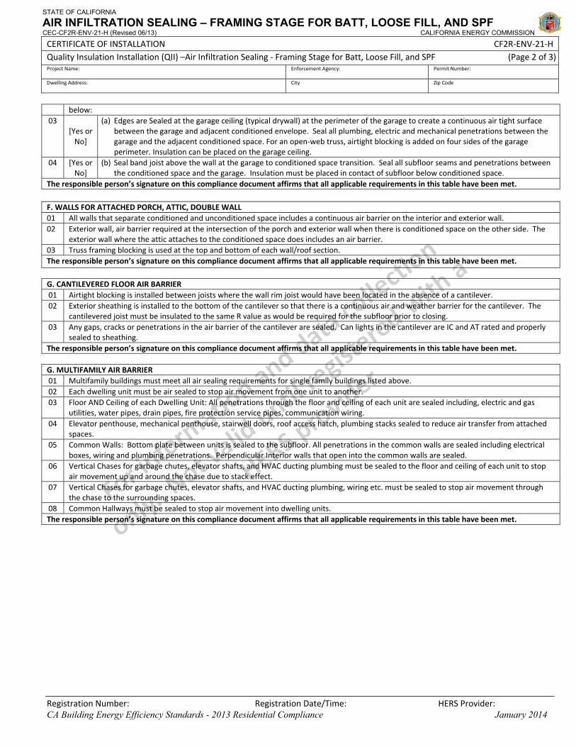
STATE OF CALIFORNIA
AIR INFILTRATION SEALING – FRAMING STAGE FOR BATT, LOOSE FILL, AND SPF CEC-CF2R-ENV-21-H (Revised 06/13) CALIFORNIA ENERGY COMMISSION
CERTIFICATE OF INSTALLATION CF2R‐ENV‐21‐H Quality Insulation Installation (QII) –Air Infiltration Sealing ‐ Framing Stage for Batt, Loose Fill, and SPF (Page 2 of 3)Project Name: Enforcement Agency: Permit Number:
Dwelling Address: City Zip Code
Registration Number: Registration Date/Time: HERS Provider: CA Building Energy Efficiency Standards - 2013 Residential Compliance January 2014
below: 03
[Yes or No]
(a) Edges are Sealed at the garage ceiling (typical drywall) at the perimeter of the garage to create a continuous air tight surface between the garage and adjacent conditioned envelope. Seal all plumbing, electric and mechanical penetrations between the garage and the adjacent conditioned space. For an open‐web truss, airtight blocking is added on four sides of the garage perimeter. Insulation can be placed on the garage ceiling.
04 [Yes or No]
(b) Seal band joist above the wall at the garage to conditioned space transition. Seal all subfloor seams and penetrations between the conditioned space and the garage. Insulation must be placed in contact of subfloor below conditioned space.
The responsible person’s signature on this compliance document affirms that all applicable requirements in this table have been met.
F. WALLS FOR ATTACHED PORCH, ATTIC, DOUBLE WALL 01 All walls that separate conditioned and unconditioned space includes a continuous air barrier on the interior and exterior wall. 02 Exterior wall, air barrier required at the intersection of the porch and exterior wall when there is conditioned space on the other side. The
exterior wall where the attic attaches to the conditioned space does includes an air barrier. 03 Truss framing blocking is used at the top and bottom of each wall/roof section. The responsible person’s signature on this compliance document affirms that all applicable requirements in this table have been met.
G. CANTILEVERED FLOOR AIR BARRIER 01 Airtight blocking is installed between joists where the wall rim joist would have been located in the absence of a cantilever. 02 Exterior sheathing is installed to the bottom of the cantilever so that there is a continuous air and weather barrier for the cantilever. The
cantilevered joist must be insulated to the same R value as would be required for the subfloor prior to closing. 03 Any gaps, cracks or penetrations in the air barrier of the cantilever are sealed. Can lights in the cantilever are IC and AT rated and properly
sealed to sheathing. The responsible person’s signature on this compliance document affirms that all applicable requirements in this table have been met. G. MULTIFAMILY AIR BARRIER 01 Multifamily buildings must meet all air sealing requirements for single family buildings listed above. 02 Each dwelling unit must be air sealed to stop air movement from one unit to another. 03 Floor AND Ceiling of each Dwelling Unit: All penetrations through the floor and ceiling of each unit are sealed including, electric and gas
utilities, water pipes, drain pipes, fire protection service pipes, communication wiring. 04 Elevator penthouse, mechanical penthouse, stairwell doors, roof access hatch, plumbing stacks sealed to reduce air transfer from attached
spaces. 05 Common Walls: Bottom plate between units is sealed to the subfloor. All penetrations in the common walls are sealed including electrical
boxes, wiring and plumbing penetrations. Perpendicular Interior walls that open into the common walls are sealed. 06 Vertical Chases for garbage chutes, elevator shafts, and HVAC ducting plumbing must be sealed to the floor and ceiling of each unit to stop
air movement up and around the chase due to stack effect. 07 Vertical Chases for garbage chutes, elevator shafts, and HVAC ducting plumbing, wiring etc. must be sealed to stop air movement through
the chase to the surrounding spaces. 08 Common Hallways must be sealed to stop air movement into dwelling units. The responsible person’s signature on this compliance document affirms that all applicable requirements in this table have been met.

STATE OF CALIFORNIA
AIR INFILTRATION SEALING – FRAMING STAGE FOR BATT, LOOSE FILL, AND SPF CEC-CF2R-ENV-21-H (Revised 06/13) CALIFORNIA ENERGY COMMISSION
CERTIFICATE OF INSTALLATION CF2R‐ENV‐21‐H Quality Insulation Installation (QII) –Air Infiltration Sealing ‐ Framing Stage for Batt, Loose Fill, and SPF (Page 3 of 3)Project Name: Enforcement Agency: Permit Number:
Dwelling Address: City Zip Code
Registration Number: Registration Date/Time: HERS Provider: CA Building Energy Efficiency Standards - 2013 Residential Compliance January 2014
DOCUMENTATION AUTHOR'S DECLARATION STATEMENT1. I certify that this Certificate of Installation documentation is accurate and complete.
Documentation Author Name: Documentation Author Signature:
Documentation Author Company Name: Date Signed:
Address: CEA/HERS Certification Identification (If applicable):
City/State/Zip: Phone:
RESPONSIBLE PERSON'S DECLARATION STATEMENT
I certify the following under penalty of perjury, under the laws of the State of California:
1. The information provided on this Certificate of Installation is true and correct.
2. I am eligible under Division 3 of the Business and Professions Code in the applicable classification to accept responsibility for the system design, construction, or installation of features, materials, components, or manufactured devices for the scope of work identified on this Certificate of Installation and attest to the declarations in this statement (responsible builder/installer), otherwise I am an authorized representative of the responsible builder/installer.
3. The constructed or installed features, materials, components or manufactured devices (the installation) identified on this Certificate of Installation conforms to all applicable codes and regulations, and the installation conforms to the requirements given on the plans and specifications approved by the enforcement agency.
4. I understand that a HERS rater will check the installation to verify compliance, and that if such checking identifies defects; I am required to take corrective action at my expense. I understand that Energy Commission and HERS Provider representatives will also perform quality assurance checking of installations, including those approved as part of a sample group but not checked by a HERS rater, and if those installations fail to meet the requirements of such quality assurance checking, the required corrective action and additional checking/testing of other installations in that HERS sample group will be performed at my expense.
5. I reviewed a copy of the Certificate of Compliance approved by the enforcement agency that identifies the specific requirements for the scope of construction or installation identified on this Certificate of Installation, and I have ensured that the requirements that apply to the construction or installation have been met.
6. I will ensure that a registered copy of this Certificate of Installation shall be posted, or made available with the building permit(s) issued for the building, and made available to the enforcement agency for all applicable inspections. I understand that a registered copy of this Certificate of Installation is required to be included with the documentation the builder provides to the building owner at occupancy.
Responsible Builder/Installer Name: Responsible Builder/Installer Signature:
Company Name: (Installing Subcontractor or General Contractor or Builder/Owner) Position With Company (Title):
Address: CSLB License:
City/State/Zip: Phone Date Signed:
Third Party Quality Control Program (TPQCP) Status: Name of TPQCP (if applicable):
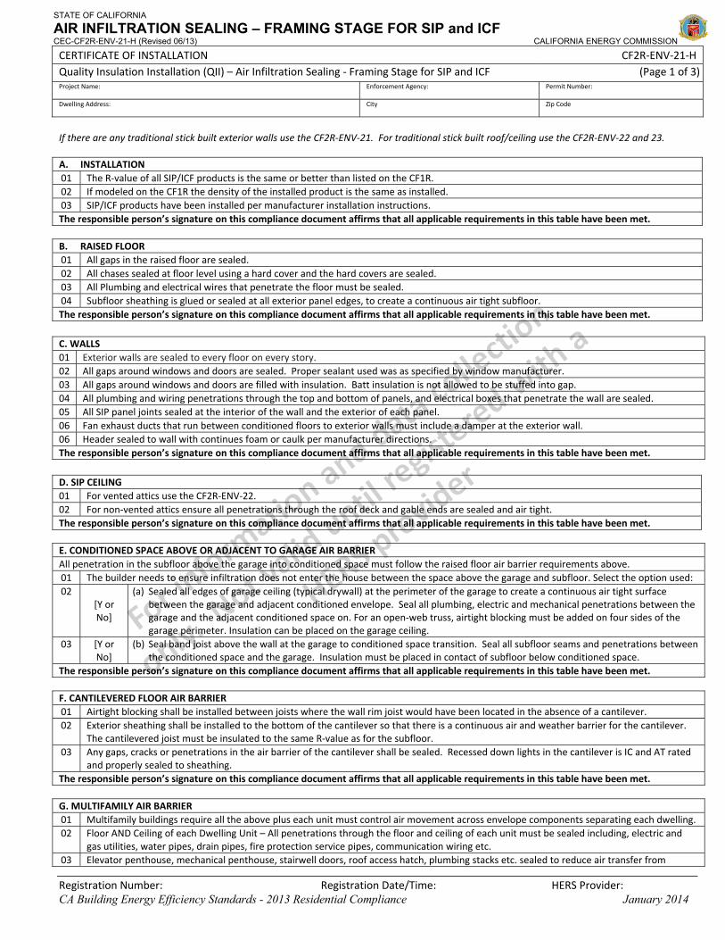
STATE OF CALIFORNIA
AIR INFILTRATION SEALING – FRAMING STAGE FOR SIP and ICF CEC-CF2R-ENV-21-H (Revised 06/13) CALIFORNIA ENERGY COMMISSION
CERTIFICATE OF INSTALLATION CF2R‐ENV‐21‐H Quality Insulation Installation (QII) – Air Infiltration Sealing ‐ Framing Stage for SIP and ICF (Page 1 of 3)Project Name: Enforcement Agency: Permit Number:
Dwelling Address: City Zip Code
Registration Number: Registration Date/Time: HERS Provider: CA Building Energy Efficiency Standards - 2013 Residential Compliance January 2014
If there are any traditional stick built exterior walls use the CF2R‐ENV‐21. For traditional stick built roof/ceiling use the CF2R‐ENV‐22 and 23. A. INSTALLATION 01 The R‐value of all SIP/ICF products is the same or better than listed on the CF1R. 02 If modeled on the CF1R the density of the installed product is the same as installed. 03 SIP/ICF products have been installed per manufacturer installation instructions. The responsible person’s signature on this compliance document affirms that all applicable requirements in this table have been met. B. RAISED FLOOR 01 All gaps in the raised floor are sealed. 02 All chases sealed at floor level using a hard cover and the hard covers are sealed. 03 All Plumbing and electrical wires that penetrate the floor must be sealed. 04 Subfloor sheathing is glued or sealed at all exterior panel edges, to create a continuous air tight subfloor. The responsible person’s signature on this compliance document affirms that all applicable requirements in this table have been met.
C. WALLS 01 Exterior walls are sealed to every floor on every story. 02 All gaps around windows and doors are sealed. Proper sealant used was as specified by window manufacturer. 03 All gaps around windows and doors are filled with insulation. Batt insulation is not allowed to be stuffed into gap. 04 All plumbing and wiring penetrations through the top and bottom of panels, and electrical boxes that penetrate the wall are sealed. 05 All SIP panel joints sealed at the interior of the wall and the exterior of each panel. 06 Fan exhaust ducts that run between conditioned floors to exterior walls must include a damper at the exterior wall. 06 Header sealed to wall with continues foam or caulk per manufacturer directions. The responsible person’s signature on this compliance document affirms that all applicable requirements in this table have been met.
D. SIP CEILING 01 For vented attics use the CF2R‐ENV‐22. 02 For non‐vented attics ensure all penetrations through the roof deck and gable ends are sealed and air tight. The responsible person’s signature on this compliance document affirms that all applicable requirements in this table have been met. E. CONDITIONED SPACE ABOVE OR ADJACENT TO GARAGE AIR BARRIER All penetration in the subfloor above the garage into conditioned space must follow the raised floor air barrier requirements above. 01 The builder needs to ensure infiltration does not enter the house between the space above the garage and subfloor. Select the option used: 02
[Y or No]
(a) Sealed all edges of garage ceiling (typical drywall) at the perimeter of the garage to create a continuous air tight surface between the garage and adjacent conditioned envelope. Seal all plumbing, electric and mechanical penetrations between the garage and the adjacent conditioned space on. For an open‐web truss, airtight blocking must be added on four sides of the garage perimeter. Insulation can be placed on the garage ceiling.
03 [Y or No]
(b) Seal band joist above the wall at the garage to conditioned space transition. Seal all subfloor seams and penetrations between the conditioned space and the garage. Insulation must be placed in contact of subfloor below conditioned space.
The responsible person’s signature on this compliance document affirms that all applicable requirements in this table have been met. F. CANTILEVERED FLOOR AIR BARRIER 01 Airtight blocking shall be installed between joists where the wall rim joist would have been located in the absence of a cantilever. 02 Exterior sheathing shall be installed to the bottom of the cantilever so that there is a continuous air and weather barrier for the cantilever.
The cantilevered joist must be insulated to the same R‐value as for the subfloor. 03 Any gaps, cracks or penetrations in the air barrier of the cantilever shall be sealed. Recessed down lights in the cantilever is IC and AT rated
and properly sealed to sheathing. The responsible person’s signature on this compliance document affirms that all applicable requirements in this table have been met. G. MULTIFAMILY AIR BARRIER 01 Multifamily buildings require all the above plus each unit must control air movement across envelope components separating each dwelling. 02 Floor AND Ceiling of each Dwelling Unit – All penetrations through the floor and ceiling of each unit must be sealed including, electric and
gas utilities, water pipes, drain pipes, fire protection service pipes, communication wiring etc. 03 Elevator penthouse, mechanical penthouse, stairwell doors, roof access hatch, plumbing stacks etc. sealed to reduce air transfer from
STATE OF CALIFORNIA
AIR INFILTRATION SEALING – FRAMING STAGE FOR SIP and ICF CEC-CF2R-ENV-21-H (Revised 06/13) CALIFORNIA ENERGY COMMISSION
CERTIFICATE OF INSTALLATION CF2R‐ENV‐21‐H Quality Insulation Installation (QII) – Air Infiltration Sealing ‐ Framing Stage for SIP and ICF (Page 2 of 3)Project Name: Enforcement Agency: Permit Number:
Dwelling Address: City Zip Code
Registration Number: Registration Date/Time: HERS Provider: CA Building Energy Efficiency Standards - 2013 Residential Compliance January 2014
attached spaces. 04 Common Walls – Bottom plate between units must be sealed to the subfloor. All penetration in the common walls is sealed. Interior walls
that open into the common walls must be sealed. 05 Vertical Chases – All vertical chases are sealed at the floor and ceiling of each unit so air cannot transfer from first floor to second floor
around chase. 06 Vertical Chases –The chases such as garbage chutes, elevator shafts, and HVAC ducting are sealed to stop air movement through the chase
to surrounding spaces. 07 Common Hallways – Penetrations between dwelling unit and common hallways are sealed including doors to the dwelling unit are gasketed
or made substantially airtight. The responsible person’s signature on this compliance document affirms that all applicable requirements in this table have been met.
STATE OF CALIFORNIA
AIR INFILTRATION SEALING – FRAMING STAGE FOR SIP and ICF CEC-CF2R-ENV-21-H (Revised 06/13) CALIFORNIA ENERGY COMMISSION
CERTIFICATE OF INSTALLATION CF2R‐ENV‐21‐H Quality Insulation Installation (QII) – Air Infiltration Sealing ‐ Framing Stage for SIP and ICF (Page 3 of 3)Project Name: Enforcement Agency: Permit Number:
Dwelling Address: City Zip Code
Registration Number: Registration Date/Time: HERS Provider: CA Building Energy Efficiency Standards - 2013 Residential Compliance January 2014
DOCUMENTATION AUTHOR'S DECLARATION STATEMENT1. I certify that this Certificate of Installation documentation is accurate and complete.
Documentation Author Name: Documentation Author Signature:
Documentation Author Company Name: Date Signed:
Address: CEA/HERS Certification Identification (If applicable):
City/State/Zip: Phone:
RESPONSIBLE PERSON'S DECLARATION STATEMENT
I certify the following under penalty of perjury, under the laws of the State of California:
1. The information provided on this Certificate of Installation is true and correct.
2. I am eligible under Division 3 of the Business and Professions Code in the applicable classification to accept responsibility for the system design, construction, or installation of features, materials, components, or manufactured devices for the scope of work identified on this Certificate of Installation and attest to the declarations in this statement (responsible builder/installer), otherwise I am an authorized representative of the responsible builder/installer.
3. The constructed or installed features, materials, components or manufactured devices (the installation) identified on this Certificate of Installation conforms to all applicable codes and regulations, and the installation conforms to the requirements given on the plans and specifications approved by the enforcement agency.
4. I understand that a HERS rater will check the installation to verify compliance, and that if such checking identifies defects; I am required to take corrective action at my expense. I understand that Energy Commission and HERS Provider representatives will also perform quality assurance checking of installations, including those approved as part of a sample group but not checked by a HERS rater, and if those installations fail to meet the requirements of such quality assurance checking, the required corrective action and additional checking/testing of other installations in that HERS sample group will be performed at my expense.
5. I reviewed a copy of the Certificate of Compliance approved by the enforcement agency that identifies the specific requirements for the scope of construction or installation identified on this Certificate of Installation, and I have ensured that the requirements that apply to the construction or installation have been met.
6. I will ensure that a registered copy of this Certificate of Installation shall be posted, or made available with the building permit(s) issued for the building, and made available to the enforcement agency for all applicable inspections. I understand that a registered copy of this Certificate of Installation is required to be included with the documentation the builder provides to the building owner at occupancy.
Responsible Builder/Installer Name: Responsible Builder/Installer Signature:
Company Name: (Installing Subcontractor or General Contractor or Builder/Owner) Position With Company (Title):
Address: CSLB License:
City/State/Zip: Phone Date Signed:
Third Party Quality Control Program (TPQCP) Status: Name of TPQCP (if applicable):
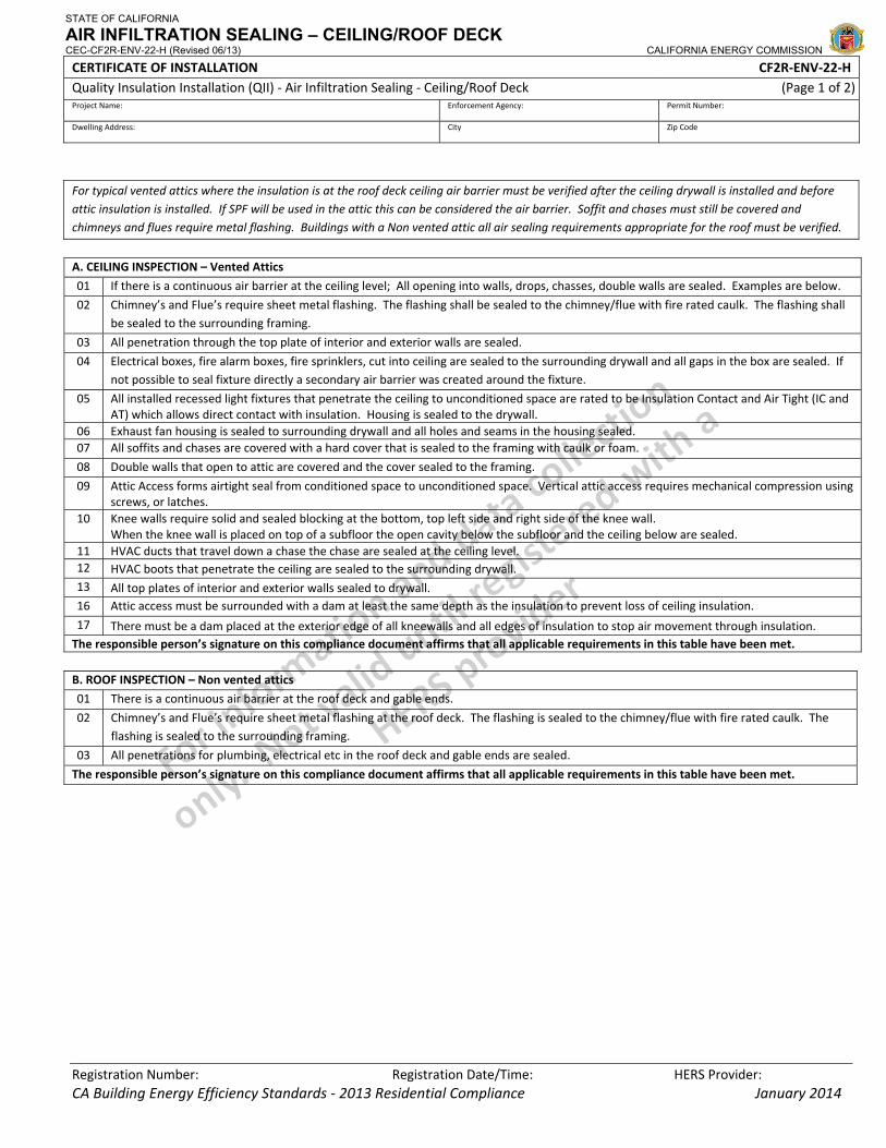
STATE OF CALIFORNIA
AIR INFILTRATION SEALING – CEILING/ROOF DECK CEC-CF2R-ENV-22-H (Revised 06/13) CALIFORNIA ENERGY COMMISSION
CERTIFICATE OF INSTALLATION CF2R‐ENV‐22‐H Quality Insulation Installation (QII) ‐ Air Infiltration Sealing ‐ Ceiling/Roof Deck (Page 1 of 2)Project Name: Enforcement Agency: Permit Number:
Dwelling Address: City Zip Code
Registration Number: Registration Date/Time: HERS Provider: CA Building Energy Efficiency Standards ‐ 2013 Residential Compliance January 2014
For typical vented attics where the insulation is at the roof deck ceiling air barrier must be verified after the ceiling drywall is installed and before attic insulation is installed. If SPF will be used in the attic this can be considered the air barrier. Soffit and chases must still be covered and chimneys and flues require metal flashing. Buildings with a Non vented attic all air sealing requirements appropriate for the roof must be verified.
A. CEILING INSPECTION – Vented Attics
01 If there is a continuous air barrier at the ceiling level; All opening into walls, drops, chasses, double walls are sealed. Examples are below.
02 Chimney’s and Flue’s require sheet metal flashing. The flashing shall be sealed to the chimney/flue with fire rated caulk. The flashing shall be sealed to the surrounding framing.
03 All penetration through the top plate of interior and exterior walls are sealed.
04 Electrical boxes, fire alarm boxes, fire sprinklers, cut into ceiling are sealed to the surrounding drywall and all gaps in the box are sealed. If not possible to seal fixture directly a secondary air barrier was created around the fixture.
05 All installed recessed light fixtures that penetrate the ceiling to unconditioned space are rated to be Insulation Contact and Air Tight (IC and AT) which allows direct contact with insulation. Housing is sealed to the drywall.
06 Exhaust fan housing is sealed to surrounding drywall and all holes and seams in the housing sealed. 07 All soffits and chases are covered with a hard cover that is sealed to the framing with caulk or foam.
08 Double walls that open to attic are covered and the cover sealed to the framing.
09 Attic Access forms airtight seal from conditioned space to unconditioned space. Vertical attic access requires mechanical compression using screws, or latches.
10 Knee walls require solid and sealed blocking at the bottom, top left side and right side of the knee wall. When the knee wall is placed on top of a subfloor the open cavity below the subfloor and the ceiling below are sealed.
11 HVAC ducts that travel down a chase the chase are sealed at the ceiling level. 12 HVAC boots that penetrate the ceiling are sealed to the surrounding drywall. 13 All top plates of interior and exterior walls sealed to drywall. 16 Attic access must be surrounded with a dam at least the same depth as the insulation to prevent loss of ceiling insulation.
17 There must be a dam placed at the exterior edge of all kneewalls and all edges of insulation to stop air movement through insulation. The responsible person’s signature on this compliance document affirms that all applicable requirements in this table have been met.
B. ROOF INSPECTION – Non vented attics
01 There is a continuous air barrier at the roof deck and gable ends.
02 Chimney’s and Flue’s require sheet metal flashing at the roof deck. The flashing is sealed to the chimney/flue with fire rated caulk. The flashing is sealed to the surrounding framing.
03 All penetrations for plumbing, electrical etc in the roof deck and gable ends are sealed.
The responsible person’s signature on this compliance document affirms that all applicable requirements in this table have been met.
STATE OF CALIFORNIA
AIR INFILTRATION SEALING – CEILING/ROOF DECK CEC-CF2R-ENV-22-H (Revised 06/13) CALIFORNIA ENERGY COMMISSION
CERTIFICATE OF INSTALLATION CF2R‐ENV‐22‐H Quality Insulation Installation (QII) ‐ Air Infiltration Sealing ‐ Ceiling/Roof Deck (Page 2 of 2)Project Name: Enforcement Agency: Permit Number:
Dwelling Address: City Zip Code
Registration Number: Registration Date/Time: HERS Provider: CA Building Energy Efficiency Standards ‐ 2013 Residential Compliance January 2014
DOCUMENTATION AUTHOR'S DECLARATION STATEMENT1. I certify that this Certificate of Installation documentation is accurate and complete.
Documentation Author Name: Documentation Author Signature:
Documentation Author Company Name: Date Signed:
Address: CEA/HERS Certification Identification (If applicable):
City/State/Zip: Phone:
RESPONSIBLE PERSON'S DECLARATION STATEMENT
I certify the following under penalty of perjury, under the laws of the State of California:
1. The information provided on this Certificate of Installation is true and correct.
2. I am eligible under Division 3 of the Business and Professions Code in the applicable classification to accept responsibility for the system design, construction, or installation of features, materials, components, or manufactured devices for the scope of work identified on this Certificate of Installation and attest to the declarations in this statement (responsible builder/installer), otherwise I am an authorized representative of the responsible builder/installer.
3. The constructed or installed features, materials, components or manufactured devices (the installation) identified on this Certificate of Installation conforms to all applicable codes and regulations, and the installation conforms to the requirements given on the plans and specifications approved by the enforcement agency.
4. I understand that a HERS rater will check the installation to verify compliance, and that if such checking identifies defects; I am required to take corrective action at my expense. I understand that Energy Commission and HERS Provider representatives will also perform quality assurance checking of installations, including those approved as part of a sample group but not checked by a HERS rater, and if those installations fail to meet the requirements of such quality assurance checking, the required corrective action and additional checking/testing of other installations in that HERS sample group will be performed at my expense.
5. I reviewed a copy of the Certificate of Compliance approved by the enforcement agency that identifies the specific requirements for the scope of construction or installation identified on this Certificate of Installation, and I have ensured that the requirements that apply to the construction or installation have been met.
6. I will ensure that a registered copy of this Certificate of Installation shall be posted, or made available with the building permit(s) issued for the building, and made available to the enforcement agency for all applicable inspections. I understand that a registered copy of this Certificate of Installation is required to be included with the documentation the builder provides to the building owner at occupancy.
Responsible Builder/Installer Name: Responsible Builder/Installer Signature:
Company Name: (Installing Subcontractor or General Contractor or Builder/Owner) Position With Company (Title):
Address: CSLB License:
City/State/Zip: Phone Date Signed:
Third Party Quality Control Program (TPQCP) Status: Name of TPQCP (if applicable):
STATE OF CALIFORNIA
INSULATION STAGE CEC-CF2R-ENV-23-H (Revised 06/13) CALIFORNIA ENERGY COMMISSION
CERTIFICATE OF INSTALLATION CF2R‐ENV‐23‐H Quality Insulation Installation (QII) ‐ Insulation Stage (Page 1 of 4)Project Name: Enforcement Agency: Permit Number:
Dwelling Address: City Zip Code
Registration Number: Registration Date/Time: HERS Provider: CA Building Energy Efficiency Standards ‐ 2013 Residential Compliance January 2014
A. QUALITY INSULATION INSTALLATION (QII) INSULATION STAGE 01 Insulation shall be installed to the requirements of Reference Residential Appendices, RA 3.5. 02 Air barrier installation and preparation for insulation was done at framing stage prior to insulation being installed 03 All structural framing areas shall be insulated in a manner that resists thermal bridging of the assembly separating conditioned from
unconditioned space. Structural bracing, tie‐downs, and framing of steel, or specialized framing used to meet structural requirements of the CBC are allowed and must be insulated. These areas shall be called out on the building plans with diagrams and/or specific design drawings indicating the R‐value of insulation and fastening method to be used. It is recommended that spray foam be use.
04 Medium and light density Spray Foam (SPF) manufacturers claim various R‐values per inch. In California the maximum R‐value that can be claimed for close cell SPF (ccSPF) is an R‐value of 5.8 per inch and for open cell SPF (ocSPF) is an R‐value of 3.6 per inch, unless documentation is provided showing that the product and/or manufacturer has a current ICC Evaluation Service Report (ESR) that shows compliance with Acceptance Criteria for Spray‐Applied Foam Plastic Insulation‐‐AC377.
05 All insulation was installed to the manufactures insulation installation instructions. The responsible person’s signature on this compliance document affirms that all applicable requirements in this table have been met. B. QUALITY OF ALL INSTALLED INSULATION 01 Installed insulation R‐values is the same or greater than specified on the CF1R. 02 No gaps or voids between the insulation and framing. 03 Gaps between studs shall be filled with insulation. 04 Batt ‐ ensure the ends are cut so there are no gaps. 05 Batt ‐ Insulation is cut around obstructions like electrical boxes and no gaps exist. 06 Batt ‐ insulation is not compressed (no stuffing of the insulation into the cavity). 07 Batt insulation is delaminated around all plumbing and electrical lines in ceilings, walls and floors. 08 An air barrier is installed at all exposed edge of insulation. 09 Loose‐fill insulation installed to the minimum installed weight per square foot per the manufacturer's labeled R‐value specification. 10 Rigid board insulation shall be installed according to the manufacturer's installation instructions. 11 SPF insulation shall be spray‐applied to fully adhere to structural assembly framing, floor and ceiling joists, and other framing surfaces within
the construction cavity. 12 SPF ‐ with multiple layers applied, each foam lift (i.e. spray application) adheres to the substrate and foam interfaces. 13 SPF ‐ if values other than R‐5.8 per inch for ccSPF and R‐3.6 per inch for ocSPF is used, then an ICC Evaluation Service Report (ESR) is attached
and uploaded to the HERS provider’s web site. 14 ccSPF ‐ in areas where an air barrier is required the foam is at least two inches thick. 15 ocSPF depressions in the foam insulation surface is not greater than 1‐inch of the required thickness provided these depressions do not
exceed 10% of the surface area being insulated. 16 ocSPF insulation does completely fill cavities of 2x4 inch framing or less. 17 ocSPF cavities greater than 2x4 inch framing are filled to the thickness that meets the required R‐value used for compliance. 18 SPF installed as an air barrier is sprayed at a minimum of 5.5 inches in thickness for open cell and 2.0 inches for closed cell. 19 A CF2R‐ENV‐03 is provided with this document that specifies each type of insulation material installed. Labels or specification/data sheets
are attached to the CF2R‐ENV‐03 for each insulating material. Blown in material also includes insulation material bag labels or coverage charts.
The responsible person’s signature on this compliance document affirms that all applicable requirements in this table have been met. C. CEILING/ROOF INSULATION 01 Insulation extends to the outside edge of the exterior top plates and is flush against any ventilation dams/baffles. 02 Insulation is in direct contact with ceiling so there are no gaps between the ceiling and the insulation. 03 Chimneys and flues (except for zero clearance) require sheet metal collar around the stack. The collar must be at least as tall as the depth of
the insulation. The collar shall be 1” from the chimney/flue for double wall vent, and 6” from the chimney/flue for single wall vent” unless manufacturer requires otherwise. The collar must be sealed to the ceiling with high temperature sealant to prevent air leakage. The insulation is in contact with the sheet metal collar.
04 Required eave ventilation shall not be obstructed ‐ the net free‐ventilation area of the eave vent is maintained
05 Eave vent baffles are installed to prevent air movement under or into the ceiling insulation 06 Recessed downlights are covered with insulation. If they are not covered to the same depth as required by the CF1R for ceiling insulation
then a area weighted calculation is required. Recessed downlights are AT and IC rated. 07 Recessed downlights where SPF insulation is installed shall: (Note: SPF insulation shall not be applied directly to recessed lighting fixtures)
(a) be covered with a minimum of 1.5 inches of mineral fiber insulation, or
STATE OF CALIFORNIA
INSULATION STAGE CEC-CF2R-ENV-23-H (Revised 06/13) CALIFORNIA ENERGY COMMISSION
CERTIFICATE OF INSTALLATION CF2R‐ENV‐23‐H Quality Insulation Installation (QII) ‐ Insulation Stage (Page 2 of 4)Project Name: Enforcement Agency: Permit Number:
Dwelling Address: City Zip Code
Registration Number: Registration Date/Time: HERS Provider: CA Building Energy Efficiency Standards ‐ 2013 Residential Compliance January 2014
(b) be enclosed in a box fabricated from 1/4 inch plywood, 18 gauge metal, 3/8 inch hard board or gypboard. Hard board or gypboard do not cause a recessed downlights to meet the zero clearance insulation contact requirements.
08 Walkways and mechanical platforms are insulated to the same R‐value as required by the CF1R for ceiling insulation. If not an area weighted calculation is completed and turned in with this form.
09 Soffits, chasses, drops have a sealed hard cover and the insulation is in direct contact with the hard cover. 10 Knee walls – an air dam the full depth of the ceiling insulation is added to the exterior edge of the knee wall so the ceiling insulation overlaps
the knee wall to the full depth of the ceiling insulation. 11 Attic access doors are insulated to the same R‐value required by the CF1R for roof insulation and the insulation is permanently attached
using adhesive or mechanical fasteners. Preferred method is rigid insulation. 12 Attic Access forms airtight seal from conditioned space to unconditioned space. Vertical attic access requires mechanical compression using
screws, or latches. 13 Attic access must have a dam around the access to at least the same depth as the insulation. 14 Insulation batts must be cut to fit around cross bracings and truss webs. 15 Attic rulers appropriate to the material are installed and evenly distributed throughout the attic to verify Depth (one ruler for every 250
square feet) The rulers are clearly readable from the attic access and scaled to read inches of insulation and the R‐value installed. 16 Loose fill and SPF insulation a HERS rater shall measure the installed thickness (include low and high areas) and density of insulation in at
least 6 random locations on walls, roof/ceilings and floors to ensure minimum thickness levels and the installed density meets the R‐value specified on the Certificate of Compliance, and are consistent with the manufacturer's coverage chart.
17 Steel‐framed kneewalls, skylight shafts, and gable ends, external surfaces of steel studs are covered with insulation The responsible person’s signature on this compliance document affirms that all applicable requirements in this table have been met. D. WALL INSULATION 01 Batts, loose fill mineral fiber, mineral and natural wool, and cellulose: fills cavity and is in contact with air barrier on six sides. 02 ocSPF: completely fill cavities of 2x4 inch framing or less. Not required to fill cavities greater than 2x4 inch framing unless required to meet
R‐value. 03 ccSPF: insulation is not required to fill the cavities of framed assemblies unless required to meet R‐value. 04 Double walls and bump‐outs ‐ insulation fills the cavity, or additional air barrier is installed so the insulation fills the cavity and is in contact
with the insulation on all six sides unless SPF is used. Insulation shall be installed on the exterior of the double walls/bump‐outs. 05 Low expanding foam used around windows and doors, if allowed by the manufacturer. If not allowed fill cavity with insulation. Batts are not
allowed to be stuffed into space. 06 Electrical panel in exterior insulated wall the panel is air tight and insulation is installed behind the panel. 07 Skylight shafts and attic knee wall insulation must meet all the requirements for walls and is in contact with the air barrier on six sides unless
SPF is used. 08 Skylight shafts and attic kneewalls insulation shall be in full contact with the drywall or other interior wall finish. Batt insulation must be cut
to fit around 2x4’s that are laid flat. 09 Skylight shafts and attic kneewalls shall be completely enclosed by vertical and horizontal framing, including horizontal plates at top and
bottom of the insulation. 10 Band/Rim joists are insulated to the same R‐value as the wall. The responsible person’s signature on this compliance document affirms that all applicable requirements in this table have been met. E. RAISED FLOOR INSULATION QUALITY 01 Insulation is in full contact with subfloor. 02 Insulation hangers are spaced at 18 inches or less, insulation hangers do not compress insulation. 03 Netting or mesh can be used if the cavity under the floor is filled and in contact with the subfloor. 04 When daylight basements are adjacent to crawlspaces, if the basement is conditioned the walls adjacent to the crawlspace are insulated to
the R‐value listed on the CF1R. This includes framed stem walls, and vertical concrete retaining walls. 05 If access to the crawlspace is from the conditioned area the raised floor includes an airtight insulated access hatch. Where possible locate
crawl space access from the exterior. The responsible person’s signature on this compliance document affirms that all applicable requirements in this table have been met.
STATE OF CALIFORNIA
INSULATION STAGE CEC-CF2R-ENV-23-H (Revised 06/13) CALIFORNIA ENERGY COMMISSION
CERTIFICATE OF INSTALLATION CF2R‐ENV‐23‐H Quality Insulation Installation (QII) ‐ Insulation Stage (Page 3 of 4)Project Name: Enforcement Agency: Permit Number:
Dwelling Address: City Zip Code
Registration Number: Registration Date/Time: HERS Provider: CA Building Energy Efficiency Standards ‐ 2013 Residential Compliance January 2014
F. FLOOR ABOVE GARAGE INSULATION QUALITY 01 Insulation must be in full contact with subfloor if the air barrier is at the band joist at the garage house wall. 02 Insulation hangers spaced at 18 inches or less, insulation hangers must not compress insulation. 03 Netting or mesh can be used if the cavity under the floor is filled and in contact with the subfloor. 04 If air barrier is at the perimeter of the garage below the conditioned subfloor then the insulation may be placed on the garage ceiling.
Perimeter of subfloor must also be insulated. The responsible person’s signature on this compliance document affirms that all applicable requirements in this table have been met. G. CANTILEVERED FLOOR INSULATION QUALITY 01 Insulation is in full contact with cantilevered subfloor. Insulation hangers are spaced at 18 inches or less, insulation hangers do not
compress insulation. Netting or mesh can be used if the cavity under the floor is filled and in contact with the subfloor. 02 Sealed Blocking shall be installed between joists where the wall rim joist would have been located in the absence of a cantilever. Insulation
shall be placed on both sides of this block. The responsible person’s signature on this compliance document affirms that all applicable requirements in this table have been met. H. ATTACHED PORCH ROOF INSULATION QUALITY 01 Exterior wall at the intersection of the porch roof is fully insulated above, below and behind the roof line. 02 Where truss framing is used, airtight blocking is used at the top and bottom of each wall/roof section and insulated. The responsible person’s signature on this compliance document affirms that all applicable requirements in this table have been met.
STATE OF CALIFORNIA
INSULATION STAGE CEC-CF2R-ENV-23-H (Revised 06/13) CALIFORNIA ENERGY COMMISSION
CERTIFICATE OF INSTALLATION CF2R‐ENV‐23‐H Quality Insulation Installation (QII) ‐ Insulation Stage (Page 4 of 4)Project Name: Enforcement Agency: Permit Number:
Dwelling Address: City Zip Code
Registration Number: Registration Date/Time: HERS Provider: CA Building Energy Efficiency Standards ‐ 2013 Residential Compliance January 2014
DOCUMENTATION AUTHOR'S DECLARATION STATEMENT1. I certify that this Certificate of Installation documentation is accurate and complete.
Documentation Author Name: Documentation Author Signature:
Documentation Author Company Name: Date Signed:
Address: CEA/HERS Certification Identification (If applicable):
City/State/Zip: Phone:
RESPONSIBLE PERSON'S DECLARATION STATEMENT
I certify the following under penalty of perjury, under the laws of the State of California:
1. The information provided on this Certificate of Installation is true and correct.
2. I am eligible under Division 3 of the Business and Professions Code in the applicable classification to accept responsibility for the system design, construction, or installation of features, materials, components, or manufactured devices for the scope of work identified on this Certificate of Installation and attest to the declarations in this statement (responsible builder/installer), otherwise I am an authorized representative of the responsible builder/installer.
3. The constructed or installed features, materials, components or manufactured devices (the installation) identified on this Certificate of Installation conforms to all applicable codes and regulations, and the installation conforms to the requirements given on the plans and specifications approved by the enforcement agency.
4. I understand that a HERS rater will check the installation to verify compliance, and that if such checking identifies defects; I am required to take corrective action at my expense. I understand that Energy Commission and HERS Provider representatives will also perform quality assurance checking of installations, including those approved as part of a sample group but not checked by a HERS rater, and if those installations fail to meet the requirements of such quality assurance checking, the required corrective action and additional checking/testing of other installations in that HERS sample group will be performed at my expense.
5. I reviewed a copy of the Certificate of Compliance approved by the enforcement agency that identifies the specific requirements for the scope of construction or installation identified on this Certificate of Installation, and I have ensured that the requirements that apply to the construction or installation have been met.
6. I will ensure that a registered copy of this Certificate of Installation shall be posted, or made available with the building permit(s) issued for the building, and made available to the enforcement agency for all applicable inspections. I understand that a registered copy of this Certificate of Installation is required to be included with the documentation the builder provides to the building owner at occupancy.
Responsible Builder/Installer Name: Responsible Builder/Installer Signature:
Company Name: (Installing Subcontractor or General Contractor or Builder/Owner) Position With Company (Title):
Address: CSLB License:
City/State/Zip: Phone Date Signed:
Third Party Quality Control Program (TPQCP) Status: Name of TPQCP (if applicable):
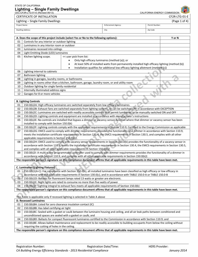
STATE OF CALIFORNIA
Lighting – Single Family Dwellings CEC-CF2R-LTG-01-E (Revised 06/13) CALIFORNIA ENERGY COMMISSION
CERTIFICATE OF INSTALLATION CF2R‐LTG‐01‐E Lighting – Single Family Dwellings (Page 1 of 4)Project Name: Enforcement Agency: Permit Number:
Dwelling Address: City Zip Code
Registration Number: Registration Date/Time: HERS Provider: CA Building Energy Efficiency Standards ‐ 2013 Residential Compliance January 2014
A. Does the scope of this project include (select Yes or No to the following options): Y or N 01 Controls for any interior or outdoor lighting 02 Luminaires in any interior room or outdoor 03 luminaires recessed into ceilings 04 Light Emitting Diode (LED) luminaires 05 Kitchen lighting scope. << user pick from list:
• Only high efficacy luminaires (method (a)); or • At least 50% of installed watts from permanently installed high efficacy lighting (method (b)) • Installation qualifies for additional low efficacy lighting allotment (method (c))
06 Lighting internal to cabinets 07 Bathroom lighting 08 Lighting in garages, laundry rooms, or bathrooms 09 Lighting in rooms other than a kitchen, bathroom, garage, laundry room, or and utility room 10 Outdoor lighting for single family residential 11 Internally illuminated address signs 12 Garages for 8 or more vehicles B. Lighting Controls 01 150.0(k)2A: High efficacy luminaires are switched separately from low efficacy luminaires. 02 150.0(k)2B: Exhaust fans are switched separately from lighting systems, or can be switched OFF in accordance with EXCEPTION 03 150.0(k)2C: Luminaires are switched with readily accessible controls that permit luminaires to be manually switched ON and OFF 04 150.0(k)2D: Lighting controls and equipment are installed in accordance with manufacturer’s instructions 05 150.0(k)2E: No controls are installed that bypass a dimmer or vacancy sensor function where that dimmer or vacancy sensor has been
installed to comply with Section 150.0(k) 06 150.0(k)2F: Lighting controls comply with the applicable requirements in Section 110.9; Certified to the Energy Commission as applicable 07 150.0(k)2G: EMCS used to comply with dimmer requirements provides the functionality of a dimmer in accordance with Section 110.9,
meets the installation certificate requirements in Section 130.4, the EMCS requirements in Section 130.5, and complies with all other applicable requirements in Section 150.0(k)2.
08 150.0(k)2H: EMCS used to comply with vacancy sensor requirements in Section 150.0(k) provides the functionality of a vacancy sensor in accordance with Section 110.9, meets the installation certificate requirements in Section 130.4, the EMCS requirements in Section 130.5, and complies with all other applicable requirements in Section 150.0(k)2.
09 150.0(k)2I: A multi‐scene programmable controller used to comply with dimmer requirements provides the functionality of a dimmer in accordance with Section 110.9, and complies with all other applicable requirements in Section 150.0(k)2.
The responsible person’s signature on this compliance document affirms that all applicable requirements in this table have been met. C. Luminaires (Lighting Fixtures) 01 150.0(k)1(A‐C): For compliance with Section 150.0(k), all installed luminaires have been classified as high efficacy or low efficacy in
accordance with the applicable requirements in Section 130.0(c), and in accordance with TABLE 150.0‐A or TABLE 150.0‐B 02 150.0(k)1D: Ballasts for fluorescent lamps rated 13 watts or greater are electronic. 03 150.0(k)1E: Night lights are rated to consume no more than five watts of power 04 150.0(k)1F: Lighting integral to exhaust fans meets all applicable requirements of Section 150.0(k) The responsible person’s signature on this compliance document affirms that all applicable requirements in this table have been met. This Table is applicable only if recessed lighting is selected in Table A above D. Recessed Luminaires 01 150.0(k)8A: Listed for zero clearance insulation contact (IC) 02 150.0(k)8B: Has label certifying air tight 03 150.0(k)8C: Sealed with a gasket or caulk between the luminaire housing and ceiling, and all air leak paths between conditioned and
unconditioned spaces are sealed with a gasket or caulk; and 04 150.0(k)8D: Ballasts for compact fluorescent luminaires certified to the Commission in accordance with Section 110.9; and 05 150.0(k)8E: Allows ballast maintenance and replacement to be readily accessible to building occupants from below the ceiling without
requiring the cutting of holes in the ceiling. The responsible person’s signature on this compliance document affirms that all applicable requirements in this table have been met.
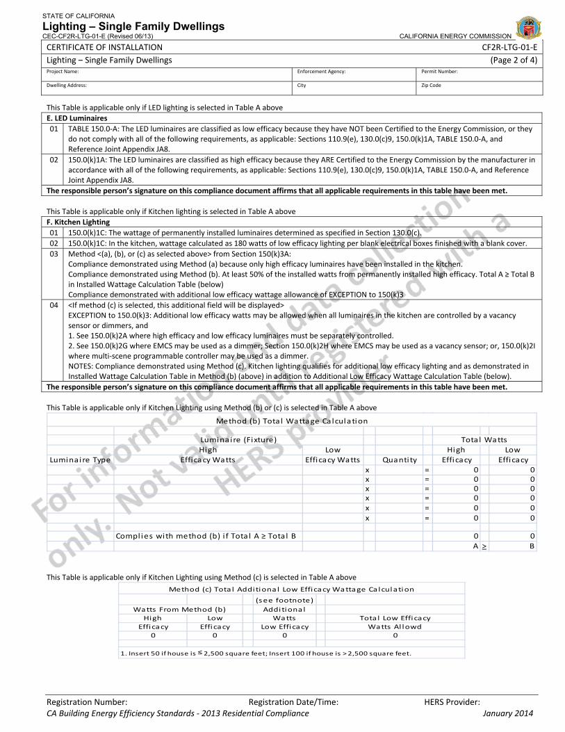
STATE OF CALIFORNIA
Lighting – Single Family Dwellings CEC-CF2R-LTG-01-E (Revised 06/13) CALIFORNIA ENERGY COMMISSION
CERTIFICATE OF INSTALLATION CF2R‐LTG‐01‐E Lighting – Single Family Dwellings (Page 2 of 4)Project Name: Enforcement Agency: Permit Number:
Dwelling Address: City Zip Code
Registration Number: Registration Date/Time: HERS Provider: CA Building Energy Efficiency Standards ‐ 2013 Residential Compliance January 2014
This Table is applicable only if LED lighting is selected in Table A above E. LED Luminaires 01 TABLE 150.0‐A: The LED luminaires are classified as low efficacy because they have NOT been Certified to the Energy Commission, or they
do not comply with all of the following requirements, as applicable: Sections 110.9(e), 130.0(c)9, 150.0(k)1A, TABLE 150.0‐A, and Reference Joint Appendix JA8.
02 150.0(k)1A: The LED luminaires are classified as high efficacy because they ARE Certified to the Energy Commission by the manufacturer in accordance with all of the following requirements, as applicable: Sections 110.9(e), 130.0(c)9, 150.0(k)1A, TABLE 150.0‐A, and Reference Joint Appendix JA8.
The responsible person’s signature on this compliance document affirms that all applicable requirements in this table have been met. This Table is applicable only if Kitchen lighting is selected in Table A above F. Kitchen Lighting 01 150.0(k)1C: The wattage of permanently installed luminaires determined as specified in Section 130.0(c). 02 150.0(k)1C: In the kitchen, wattage calculated as 180 watts of low efficacy lighting per blank electrical boxes finished with a blank cover. 03 Method <(a), (b), or (c) as selected above> from Section 150(k)3A:
Compliance demonstrated using Method (a) because only high efficacy luminaires have been installed in the kitchen. Compliance demonstrated using Method (b). At least 50% of the installed watts from permanently installed high efficacy. Total A ≥ Total B in Installed Wattage Calculation Table (below) Compliance demonstrated with additional low efficacy wattage allowance of EXCEPTION to 150(k)3
04 <If method (c) is selected, this additional field will be displayed> EXCEPTION to 150.0(k)3: Additional low efficacy watts may be allowed when all luminaires in the kitchen are controlled by a vacancy sensor or dimmers, and 1. See 150.0(k)2A where high efficacy and low efficacy luminaires must be separately controlled. 2. See 150.0(k)2G where EMCS may be used as a dimmer; Section 150.0(k)2H where EMCS may be used as a vacancy sensor; or, 150.0(k)2I where multi‐scene programmable controller may be used as a dimmer. NOTES: Compliance demonstrated using Method (c). Kitchen lighting qualifies for additional low efficacy lighting and as demonstrated in Installed Wattage Calculation Table in Method (b) (above) in addition to Additional Low Efficacy Wattage Calculation Table (below).
The responsible person’s signature on this compliance document affirms that all applicable requirements in this table have been met.
This Table is applicable only if Kitchen Lighting using Method (b) or (c) is selected in Table A above
This Table is applicable only if Kitchen Lighting using Method (c) is selected in Table A above
(see footnote)Additiona l
High Low Watts Total Low EfficacyEfficacy Effi cacy Low Efficacy Watts Al lowd
0 0 0 0
1. Insert 50 if house is ≤ 2,500 square feet; Insert 100 if house is > 2,500 square feet.
Watts From Method (b)
Method (c) Tota l Additiona l Low Efficacy Wattage Calculation
High Low High LowLuminai re Type Efficacy Watts Efficacy Watts Quanti ty Effi cacy Effi cacy
x = 0x = 0x = 0x = 0x = 0x = 0
Compl ies with method (b) i f Tota l A ≥ Total B 0A >
000000
0B
Method (b) Tota l Wattage Calculation
Luminaire (Fixture) Tota l Watts
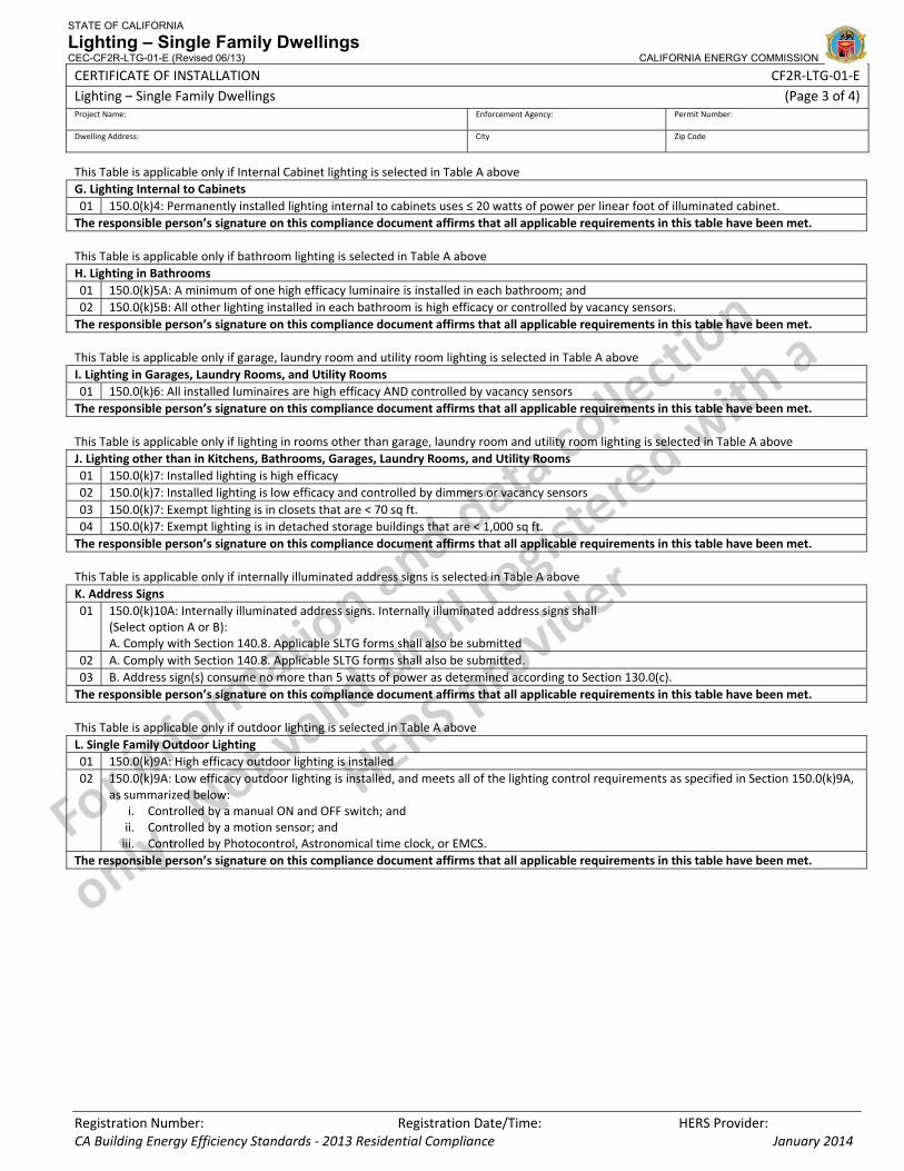
STATE OF CALIFORNIA
Lighting – Single Family Dwellings CEC-CF2R-LTG-01-E (Revised 06/13) CALIFORNIA ENERGY COMMISSION
CERTIFICATE OF INSTALLATION CF2R‐LTG‐01‐E Lighting – Single Family Dwellings (Page 3 of 4)Project Name: Enforcement Agency: Permit Number:
Dwelling Address: City Zip Code
Registration Number: Registration Date/Time: HERS Provider: CA Building Energy Efficiency Standards ‐ 2013 Residential Compliance January 2014
This Table is applicable only if Internal Cabinet lighting is selected in Table A above G. Lighting Internal to Cabinets 01 150.0(k)4: Permanently installed lighting internal to cabinets uses ≤ 20 watts of power per linear foot of illuminated cabinet. The responsible person’s signature on this compliance document affirms that all applicable requirements in this table have been met. This Table is applicable only if bathroom lighting is selected in Table A above H. Lighting in Bathrooms 01 150.0(k)5A: A minimum of one high efficacy luminaire is installed in each bathroom; and 02 150.0(k)5B: All other lighting installed in each bathroom is high efficacy or controlled by vacancy sensors. The responsible person’s signature on this compliance document affirms that all applicable requirements in this table have been met. This Table is applicable only if garage, laundry room and utility room lighting is selected in Table A above I. Lighting in Garages, Laundry Rooms, and Utility Rooms 01 150.0(k)6: All installed luminaires are high efficacy AND controlled by vacancy sensors The responsible person’s signature on this compliance document affirms that all applicable requirements in this table have been met. This Table is applicable only if lighting in rooms other than garage, laundry room and utility room lighting is selected in Table A above J. Lighting other than in Kitchens, Bathrooms, Garages, Laundry Rooms, and Utility Rooms 01 150.0(k)7: Installed lighting is high efficacy 02 150.0(k)7: Installed lighting is low efficacy and controlled by dimmers or vacancy sensors 03 150.0(k)7: Exempt lighting is in closets that are < 70 sq ft. 04 150.0(k)7: Exempt lighting is in detached storage buildings that are < 1,000 sq ft. The responsible person’s signature on this compliance document affirms that all applicable requirements in this table have been met. This Table is applicable only if internally illuminated address signs is selected in Table A above K. Address Signs 01 150.0(k)10A: Internally illuminated address signs. Internally illuminated address signs shall
(Select option A or B): A. Comply with Section 140.8. Applicable SLTG forms shall also be submitted
02 A. Comply with Section 140.8. Applicable SLTG forms shall also be submitted. 03 B. Address sign(s) consume no more than 5 watts of power as determined according to Section 130.0(c). The responsible person’s signature on this compliance document affirms that all applicable requirements in this table have been met. This Table is applicable only if outdoor lighting is selected in Table A above L. Single Family Outdoor Lighting 01 150.0(k)9A: High efficacy outdoor lighting is installed 02 150.0(k)9A: Low efficacy outdoor lighting is installed, and meets all of the lighting control requirements as specified in Section 150.0(k)9A,
as summarized below: i. Controlled by a manual ON and OFF switch; and ii. Controlled by a motion sensor; and iii. Controlled by Photocontrol, Astronomical time clock, or EMCS.
The responsible person’s signature on this compliance document affirms that all applicable requirements in this table have been met.

STATE OF CALIFORNIA
Lighting – Single Family Dwellings CEC-CF2R-LTG-01-E (Revised 06/13) CALIFORNIA ENERGY COMMISSION
CERTIFICATE OF INSTALLATION CF2R‐LTG‐01‐E Lighting – Single Family Dwellings (Page 4 of 4)Project Name: Enforcement Agency: Permit Number:
Dwelling Address: City Zip Code
Registration Number: Registration Date/Time: HERS Provider: CA Building Energy Efficiency Standards ‐ 2013 Residential Compliance January 2014
DOCUMENTATION AUTHOR'S DECLARATION STATEMENT
1. I certify that this Certificate of Installation documentation is accurate and complete.
Documentation Author Name: Documentation Author Signature:
Documentation Author Company Name: Date Signed:
Address: CEA/HERS Certification Identification (If applicable):
City/State/Zip: Phone:
RESPONSIBLE PERSON'S DECLARATION STATEMENT
I certify the following under penalty of perjury, under the laws of the State of California:
1. The information provided on this Certificate of Installation is true and correct.
2. I am eligible under Division 3 of the Business and Professions Code in the applicable classification to accept responsibility for the system design, construction, or installation of features, materials, components, or manufactured devices for the scope of work identified on this Certificate of Installation, and attest to the declarations in this statement (responsible builder/installer), otherwise I am an authorized representative of the responsible builder/installer.
3. The constructed or installed features, materials, components or manufactured devices (the installation) identified on this Certificate of Installation conforms to all applicable codes and regulations, and the installation conforms to the requirements given on the plans and specifications approved by the enforcement agency.
4. I reviewed a copy of the Certificate of Compliance approved by the enforcement agency that identifies the specific requirements for the scope of construction or installation identified on this Certificate of Installation, and I have ensured that the requirements that apply to the construction or installation have been met.
5. I will ensure that a registered copy of this Certificate of Installation shall be posted, or made available with the building permit(s) issued for the building, and made available to the enforcement agency for all applicable inspections. I understand that a registered copy of this Certificate of Installation is required to be included with the documentation the builder provides to the building owner at occupancy.
Responsible Builder/Installer Name: Responsible Builder/Installer Signature:
Company Name: (Installing Subcontractor or General Contractor or Builder/Owner) Position With Company (Title):
Address: CSLB License:
City/State/Zip: Phone Date Signed:

CERTIFICATE OF INSTALLATION – USER INSTRUCTIONS CF2R‐LTG‐01‐E Lighting – Single Family – LTG‐01 (Page 1 of 3)
CA Building Energy Efficiency Standards ‐ 2013 Residential Compliance January 2014
Instructions There are two version of the residential lighting certificate of installation. This version, the CF2R‐LTI‐01‐E, is primarily used for demonstrating compliance with the residential lighting standards for single family dwellings. The LTI‐01 shall also be used to demonstrate compliance with the residential lighting requirements for high‐rise residential dwelling units; outdoor lighting that is attached to a high‐rise residential or hotel/motel building, and is separately controlled from the inside of a dwelling unit or guest room; fire station dwelling accommodations; hotel and motel guest rooms; and, dormitory and senior housing dwelling accommodations. When using the CF2R‐LTI‐01‐E to demonstrate compliance with the lighting in the dwelling units, compliance with lighting that is not in the dwelling units, such as lighting in common areas, shall be demonstrated using the nonresidential lighting compliance documentation. The other version of the residential lighting certificate of installation, the CF2R‐LTI‐02‐E, is used for demonstrating compliance with the residential lighting standards for low‐rise multi‐family dwellings. The primary difference between the LTI‐02 and the LTI‐01 is that the LTI‐02 includes additional requirements for demonstrating compliance with residential outdoor lighting, and common areas associated with low‐rise multi‐family dwelling units. Table A This table is used to identify the scope of the work being covered by the responsible person signing this document. One person may be responsible for all of the measures in this table, or several people may each be responsible for only a portion of the measures. If several people are responsible, each person must separately fill out this certificate of installation for those measures for which they are responsible. In some situations, such as for alterations and additions, only some of the measures may be included in the total scope of work. For rows 1 through 4 and rows 6 through 12 ‐ insert ‘Y’ for each measure that is included in the scope of work, and insert ‘N’ for each measure that is not included in the scope of work. Row 5, if the scope of the work includes kitchen lighting, identify which method(s) are used to comply, as follows:
• Pick from the list “only high efficacy luminaires (method a)” if appropriate. If this method is picked, do not pick either of the other two pick options; or,
• Pick from the list “at least 50% of installed watts from permanently installed high efficacy lighting (Method (b), and, • If also appropriate, pick “an additional low efficacy lighting allotment (Method (c)”
Table B This table is a list of mandatory residential lighting control requirements. Any lighting controls installed must meet those requirements which are applicable to the scope of the work being covered by the responsible person signing this document. Table C This table is a list of mandatory residential luminaire requirements. Any luminaires installed must meet those requirements which are applicable to the scope of the work being covered by the responsible person signing this document. Additionally, some luminaires, covered in Tables D and E, have additional mandatory requirements. Table D This Table is displayed only if residential recessed lighting is selected in Table A as being included in the scope of work. This table is a list of mandatory requirements for residential recessed luminaires, which are in addition to the applicable residential luminaire requirements listed in Table C. Any recessed luminaires installed must meet those requirements which are applicable to the scope of the work being covered by the responsible person signing this document. Table E This Table is displayed only if residential LED lighting is selected in Table A as being included in the scope of work. This table is a list of mandatory requirements for residential LED luminaires, which are in addition to the applicable residential luminaire requirements listed in Tables C and D. Any LED luminaires installed must meet those requirements which are applicable to the scope of the work being covered by the responsible person signing this document. Table F This Table is displayed only if residential kitchen lighting is selected in Table A as being included in the scope of work. This table includes a list of mandatory requirements for Kitchen lighting. Any Kitchen lighting installed must meet those requirements which are applicable to the scope of the work being covered by the responsible person signing this document. For the residential kitchen lighting power requirements, this certificate of installation provides three different methods for demonstrating compliance, as follows:
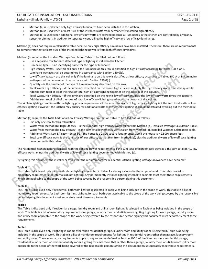
CERTIFICATE OF INSTALLATION – USER INSTRUCTIONS CF2R‐LTG‐01‐E Lighting – Single Family – LTG‐01 (Page 2 of 3)
CA Building Energy Efficiency Standards ‐ 2013 Residential Compliance January 2014
• Method (a) is used when only high efficacy luminaires have been installed in the kitchen. • Method (b) is used when at least 50% of the installed watts from permanently installed high efficacy • Method (c) is used when additional low efficacy watts are allowed because all luminaires in the kitchen are controlled by a vacancy
sensor or dimmers, in addition to separately controlling the high efficacy and low efficacy luminaires. Method (a) does not require a calculation table because only high efficacy luminaires have been installed. Therefore, there are no requirements to demonstrate that at least 50% of the installed lighting power is from high efficacy luminaires. Method (b) requires the Installed Wattage Calculation Table to be filled out, as follows:
• Use a separate row for each different type of lighting installed in the kitchen. • Luminaire Type – is an identifying name for the type of luminaire • High Efficacy Watts – use this cell only if the luminaire on this row is classified as high efficacy according to Tables 150‐A or B.
Luminaire wattage shall be determined in accordance with Section 130.0(c). • Low Efficacy Watts – use this cell only if the luminaire on this row is classified as low efficacy according to Tables 150‐A or B. Luminaire
wattage shall be determined in accordance with Section 130.0(c). • Quantity – is the number of the type of luminaire being described on this row. • Total Watts, High Efficacy – if the luminaire described on this row is high efficacy, multiply the high efficacy watts times the quantity.
Add the sum total of all of the rows of total high efficacy lighting together on the bottom of this column. • Total Watts, High Efficacy – if the luminaire described on this row is low efficacy, multiply the low efficacy watts times the quantity.
Add the sum total of all of the rows of total low efficacy lighting together on the bottom of this column. The kitchen lighting complies with the lighting power requirements if the sum total watts of high efficacy lighting is ≥ the sum total watts of low efficacy lighting. However, the kitchen may qualify for additional watts of low efficacy lighting, if also demonstrated by filling out the Method (c) table. Method (c) requires the Total Additional Low Efficacy Wattage Calculation Table to be filled out, as follows:
• Use only one row for this calculation. • Watts from Method (b), High Efficacy – is the sum total high efficacy watts taken from Method (b), Installed Wattage Calculation Table. • Watts from Method (b), Low Efficacy – is the sum total low efficacy watts taken from Method (b), Installed Wattage Calculation Table. • Additional Watts Low Efficacy – Enter 50 if the house is ≤ 2,500 square feet, or enter 100 if the house is > 2,500 square feet • Total Low Efficacy watts is the sum total of low efficacy watts taken from Method (b), plus the additional watts of low efficacy lighting
documented in this table. The residential kitchen lighting complies with the lighting power requirements if the sum total of high efficacy watts is ≥ the sum total of ALL low efficacy watts, minus the additional watts of low efficacy lighting documented with Method (c). By signing this document the installer certifies that the requirements for residential kitchen lighting wattage allowances have been met. Table G This Table is displayed only if internal cabinet lighting is selected in Table A as being included in the scope of work. This table is a list of mandatory requirements for internal cabinet lighting. Any permanently installed lighting internal to cabinets must meet those requirements which are applicable to the scope of the work being covered by the responsible person signing this document. Table H This Table is displayed only if residential bathroom lighting is selected in Table A as being included in the scope of work. This table is a list of mandatory requirements for bathroom lighting. Lighting for each bathroom applicable to the scope of the work being covered by the responsible person signing this document must separately meet these requirements. Table I This Table is displayed only if residential garage, laundry room and utility room lighting is selected in Table A as being included in the scope of work. This table is a list of mandatory requirements for garage, laundry room and utility room lighting. Lighting for each garage, laundry room and utility room applicable to the scope of the work being covered by the responsible person signing this document must separately meet these requirements. Table J This Table is displayed only if lighting in rooms other than residential garage, laundry room and utility room is selected in Table A as being included in the scope of work. This table is a list of mandatory requirements for lighting in residential rooms other than garage, laundry room and utility room. These mandatory requirements apply to any room not defined in Section 100.1 of the Standards as a residential garage, residential laundry room or residential utility room. Lighting for each room that is other than a garage, laundry room or utility room utility room applicable to the scope of the work being covered by the responsible person signing this document must separately meet these requirements.
CERTIFICATE OF INSTALLATION – USER INSTRUCTIONS CF2R‐LTG‐01‐E Lighting – Single Family – LTG‐01 (Page 3 of 3)
CA Building Energy Efficiency Standards ‐ 2013 Residential Compliance January 2014
Table K This Table is displayed only if lighting for residential internally illuminated address signs is selected in Table A as being included in the scope of work. This table is a list of mandatory requirements for internally illuminated address signs. Lighting for each internally illuminated address sign applicable to the scope of the work being covered by the responsible person signing this document must separately meet these requirements. Table L This Table is displayed only if residential outdoor lighting is selected in Table A as being included in the scope of work. This table is a list of mandatory requirements for single family outdoor lighting. Any installed outdoor lighting must meet those requirements which are applicable to the scope of the work being covered by the responsible person signing this document.
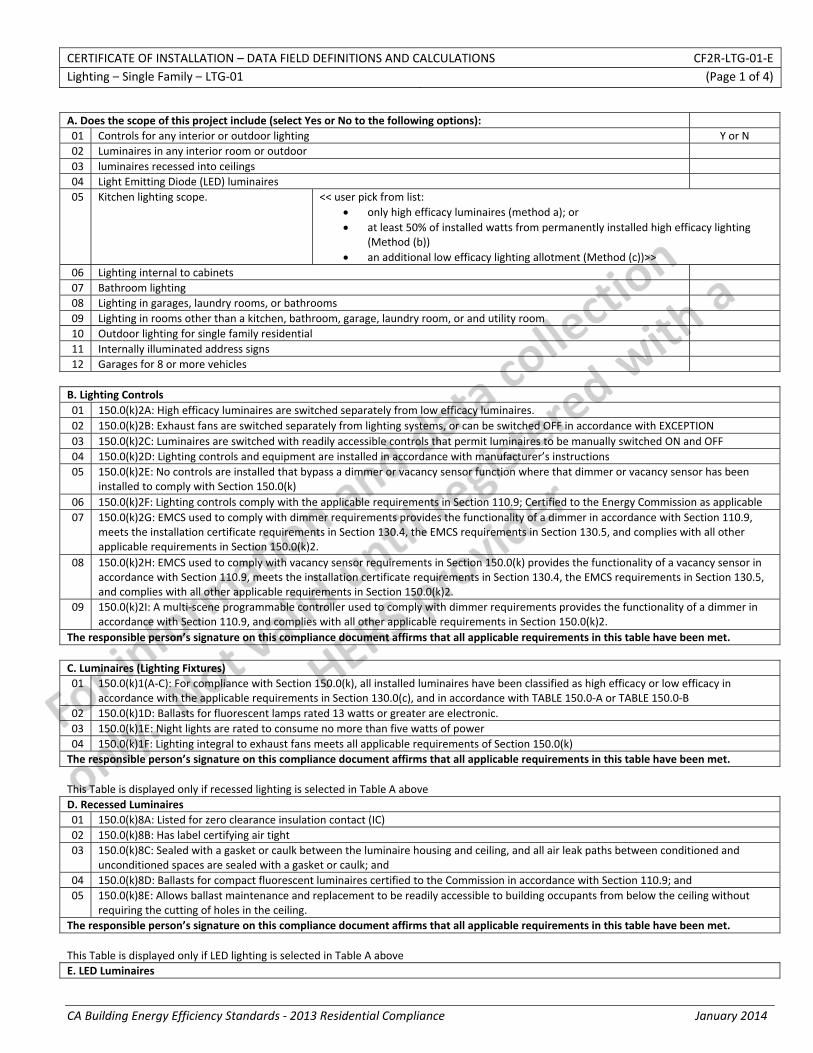
CERTIFICATE OF INSTALLATION – DATA FIELD DEFINITIONS AND CALCULATIONS CF2R‐LTG‐01‐E Lighting – Single Family – LTG‐01 (Page 1 of 4)
CA Building Energy Efficiency Standards ‐ 2013 Residential Compliance January 2014
A. Does the scope of this project include (select Yes or No to the following options): 01 Controls for any interior or outdoor lighting Y or N 02 Luminaires in any interior room or outdoor 03 luminaires recessed into ceilings 04 Light Emitting Diode (LED) luminaires 05 Kitchen lighting scope. << user pick from list:
• only high efficacy luminaires (method a); or • at least 50% of installed watts from permanently installed high efficacy lighting
(Method (b)) • an additional low efficacy lighting allotment (Method (c))>>
06 Lighting internal to cabinets 07 Bathroom lighting 08 Lighting in garages, laundry rooms, or bathrooms 09 Lighting in rooms other than a kitchen, bathroom, garage, laundry room, or and utility room 10 Outdoor lighting for single family residential 11 Internally illuminated address signs 12 Garages for 8 or more vehicles B. Lighting Controls 01 150.0(k)2A: High efficacy luminaires are switched separately from low efficacy luminaires. 02 150.0(k)2B: Exhaust fans are switched separately from lighting systems, or can be switched OFF in accordance with EXCEPTION 03 150.0(k)2C: Luminaires are switched with readily accessible controls that permit luminaires to be manually switched ON and OFF 04 150.0(k)2D: Lighting controls and equipment are installed in accordance with manufacturer’s instructions 05 150.0(k)2E: No controls are installed that bypass a dimmer or vacancy sensor function where that dimmer or vacancy sensor has been
installed to comply with Section 150.0(k) 06 150.0(k)2F: Lighting controls comply with the applicable requirements in Section 110.9; Certified to the Energy Commission as applicable 07 150.0(k)2G: EMCS used to comply with dimmer requirements provides the functionality of a dimmer in accordance with Section 110.9,
meets the installation certificate requirements in Section 130.4, the EMCS requirements in Section 130.5, and complies with all other applicable requirements in Section 150.0(k)2.
08 150.0(k)2H: EMCS used to comply with vacancy sensor requirements in Section 150.0(k) provides the functionality of a vacancy sensor in accordance with Section 110.9, meets the installation certificate requirements in Section 130.4, the EMCS requirements in Section 130.5, and complies with all other applicable requirements in Section 150.0(k)2.
09 150.0(k)2I: A multi‐scene programmable controller used to comply with dimmer requirements provides the functionality of a dimmer in accordance with Section 110.9, and complies with all other applicable requirements in Section 150.0(k)2.
The responsible person’s signature on this compliance document affirms that all applicable requirements in this table have been met. C. Luminaires (Lighting Fixtures) 01 150.0(k)1(A‐C): For compliance with Section 150.0(k), all installed luminaires have been classified as high efficacy or low efficacy in
accordance with the applicable requirements in Section 130.0(c), and in accordance with TABLE 150.0‐A or TABLE 150.0‐B 02 150.0(k)1D: Ballasts for fluorescent lamps rated 13 watts or greater are electronic. 03 150.0(k)1E: Night lights are rated to consume no more than five watts of power 04 150.0(k)1F: Lighting integral to exhaust fans meets all applicable requirements of Section 150.0(k) The responsible person’s signature on this compliance document affirms that all applicable requirements in this table have been met. This Table is displayed only if recessed lighting is selected in Table A above D. Recessed Luminaires 01 150.0(k)8A: Listed for zero clearance insulation contact (IC) 02 150.0(k)8B: Has label certifying air tight 03 150.0(k)8C: Sealed with a gasket or caulk between the luminaire housing and ceiling, and all air leak paths between conditioned and
unconditioned spaces are sealed with a gasket or caulk; and 04 150.0(k)8D: Ballasts for compact fluorescent luminaires certified to the Commission in accordance with Section 110.9; and 05 150.0(k)8E: Allows ballast maintenance and replacement to be readily accessible to building occupants from below the ceiling without
requiring the cutting of holes in the ceiling. The responsible person’s signature on this compliance document affirms that all applicable requirements in this table have been met. This Table is displayed only if LED lighting is selected in Table A above E. LED Luminaires
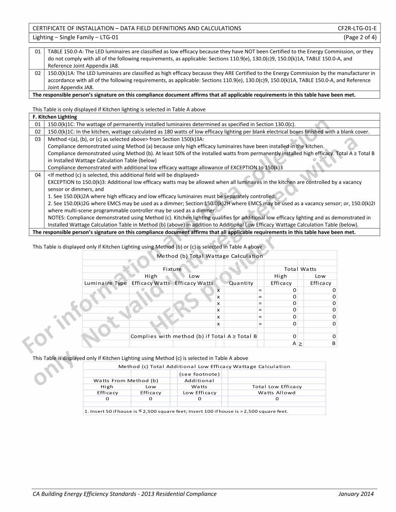
CERTIFICATE OF INSTALLATION – DATA FIELD DEFINITIONS AND CALCULATIONS CF2R‐LTG‐01‐E Lighting – Single Family – LTG‐01 (Page 2 of 4)
CA Building Energy Efficiency Standards ‐ 2013 Residential Compliance January 2014
01 TABLE 150.0‐A: The LED luminaires are classified as low efficacy because they have NOT been Certified to the Energy Commission, or they do not comply with all of the following requirements, as applicable: Sections 110.9(e), 130.0(c)9, 150.0(k)1A, TABLE 150.0‐A, and Reference Joint Appendix JA8.
02 150.0(k)1A: The LED luminaires are classified as high efficacy because they ARE Certified to the Energy Commission by the manufacturer in accordance with all of the following requirements, as applicable: Sections 110.9(e), 130.0(c)9, 150.0(k)1A, TABLE 150.0‐A, and Reference Joint Appendix JA8.
The responsible person’s signature on this compliance document affirms that all applicable requirements in this table have been met. This Table is only displayed if Kitchen lighting is selected in Table A above F. Kitchen Lighting 01 150.0(k)1C: The wattage of permanently installed luminaires determined as specified in Section 130.0(c). 02 150.0(k)1C: In the kitchen, wattage calculated as 180 watts of low efficacy lighting per blank electrical boxes finished with a blank cover. 03 Method <(a), (b), or (c) as selected above> from Section 150(k)3A:
Compliance demonstrated using Method (a) because only high efficacy luminaires have been installed in the kitchen. Compliance demonstrated using Method (b). At least 50% of the installed watts from permanently installed high efficacy. Total A ≥ Total B in Installed Wattage Calculation Table (below) Compliance demonstrated with additional low efficacy wattage allowance of EXCEPTION to 150(k)3
04 <If method (c) is selected, this additional field will be displayed> EXCEPTION to 150.0(k)3: Additional low efficacy watts may be allowed when all luminaires in the kitchen are controlled by a vacancy sensor or dimmers, and 1. See 150.0(k)2A where high efficacy and low efficacy luminaires must be separately controlled. 2. See 150.0(k)2G where EMCS may be used as a dimmer; Section 150.0(k)2H where EMCS may be used as a vacancy sensor; or, 150.0(k)2I where multi‐scene programmable controller may be used as a dimmer. NOTES: Compliance demonstrated using Method (c). Kitchen lighting qualifies for additional low efficacy lighting and as demonstrated in Installed Wattage Calculation Table in Method (b) (above) in addition to Additional Low Efficacy Wattage Calculation Table (below).
The responsible person’s signature on this compliance document affirms that all applicable requirements in this table have been met.
This Table is displayed only if Kitchen Lighting using Method (b) or (c) is selected in Table A above
High Low High LowLuminai re Type Efficacy Watts Efficacy Watts Quanti ty Effi cacy Efficacy
x = 0x = 0x = 0x = 0x = 0x = 0
Compl ies with method (b) i f Tota l A ≥ Tota l B 0A >
000000
0B
Method (b) Tota l Wattage Calculation
Fixture Tota l Watts
This Table is displayed only if Kitchen Lighting using Method (c) is selected in Table A above
(see footnote)Additiona l
High Low Watts Total Low EfficacyEfficacy Effi cacy Low Efficacy Watts Al lowd
0 0 0 0
1. Insert 50 if house is ≤ 2,500 square feet; Insert 100 if house is > 2,500 square feet.
Watts From Method (b)
Method (c) Tota l Additiona l Low Efficacy Wattage Calculation
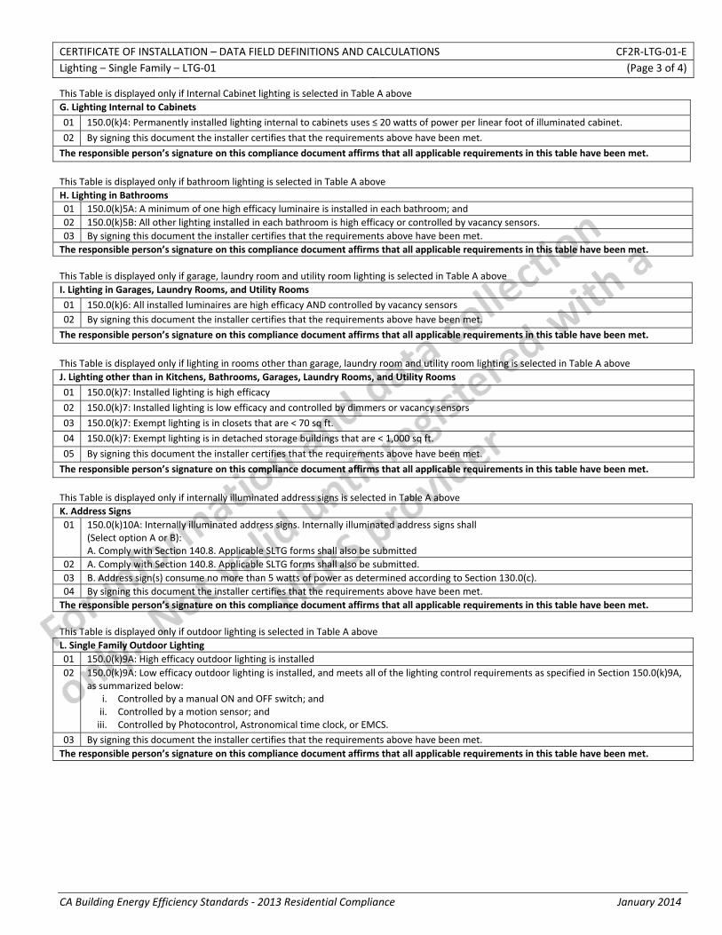
CERTIFICATE OF INSTALLATION – DATA FIELD DEFINITIONS AND CALCULATIONS CF2R‐LTG‐01‐E Lighting – Single Family – LTG‐01 (Page 3 of 4)
CA Building Energy Efficiency Standards ‐ 2013 Residential Compliance January 2014
This Table is displayed only if Internal Cabinet lighting is selected in Table A above G. Lighting Internal to Cabinets
01 150.0(k)4: Permanently installed lighting internal to cabinets uses ≤ 20 watts of power per linear foot of illuminated cabinet.
02 By signing this document the installer certifies that the requirements above have been met.
The responsible person’s signature on this compliance document affirms that all applicable requirements in this table have been met.
This Table is displayed only if bathroom lighting is selected in Table A above H. Lighting in Bathrooms 01 150.0(k)5A: A minimum of one high efficacy luminaire is installed in each bathroom; and 02 150.0(k)5B: All other lighting installed in each bathroom is high efficacy or controlled by vacancy sensors. 03 By signing this document the installer certifies that the requirements above have been met. The responsible person’s signature on this compliance document affirms that all applicable requirements in this table have been met. This Table is displayed only if garage, laundry room and utility room lighting is selected in Table A above I. Lighting in Garages, Laundry Rooms, and Utility Rooms
01 150.0(k)6: All installed luminaires are high efficacy AND controlled by vacancy sensors 02 By signing this document the installer certifies that the requirements above have been met.
The responsible person’s signature on this compliance document affirms that all applicable requirements in this table have been met.
This Table is displayed only if lighting in rooms other than garage, laundry room and utility room lighting is selected in Table A above J. Lighting other than in Kitchens, Bathrooms, Garages, Laundry Rooms, and Utility Rooms
01 150.0(k)7: Installed lighting is high efficacy
02 150.0(k)7: Installed lighting is low efficacy and controlled by dimmers or vacancy sensors
03 150.0(k)7: Exempt lighting is in closets that are < 70 sq ft.
04 150.0(k)7: Exempt lighting is in detached storage buildings that are < 1,000 sq ft.
05 By signing this document the installer certifies that the requirements above have been met.
The responsible person’s signature on this compliance document affirms that all applicable requirements in this table have been met.
This Table is displayed only if internally illuminated address signs is selected in Table A above K. Address Signs 01 150.0(k)10A: Internally illuminated address signs. Internally illuminated address signs shall
(Select option A or B): A. Comply with Section 140.8. Applicable SLTG forms shall also be submitted
02 A. Comply with Section 140.8. Applicable SLTG forms shall also be submitted. 03 B. Address sign(s) consume no more than 5 watts of power as determined according to Section 130.0(c). 04 By signing this document the installer certifies that the requirements above have been met. The responsible person’s signature on this compliance document affirms that all applicable requirements in this table have been met. This Table is displayed only if outdoor lighting is selected in Table A above L. Single Family Outdoor Lighting 01 150.0(k)9A: High efficacy outdoor lighting is installed 02 150.0(k)9A: Low efficacy outdoor lighting is installed, and meets all of the lighting control requirements as specified in Section 150.0(k)9A,
as summarized below: i. Controlled by a manual ON and OFF switch; and ii. Controlled by a motion sensor; and iii. Controlled by Photocontrol, Astronomical time clock, or EMCS.
03 By signing this document the installer certifies that the requirements above have been met. The responsible person’s signature on this compliance document affirms that all applicable requirements in this table have been met.
CERTIFICATE OF INSTALLATION – DATA FIELD DEFINITIONS AND CALCULATIONS CF2R‐LTG‐01‐E Lighting – Single Family – LTG‐01 (Page 4 of 4)
CA Building Energy Efficiency Standards ‐ 2013 Residential Compliance January 2014
DOCUMENTATION AUTHOR'S DECLARATION STATEMENT
1. I certify that this Certificate of Installation documentation is accurate and complete.
Documentation Author Name: Documentation Author Signature:
Documentation Author Company Name: Date Signed:
Address: CEA/CEPE/HERS certification identification (If applicable):
City/State/Zip: Phone:
RESPONSIBLE PERSON'S DECLARATION STATEMENT
I certify the following under penalty of perjury, under the laws of the State of California:
1. The information provided on this Certificate of Installation is true and correct.
2. I am eligible under Division 3 of the Business and Professions Code to accept responsibility for the scope of construction or installation, in the applicable classification, for the scope of work specified on this Certificate of Installation (responsible builder/installer), otherwise I am an authorized representative of the responsible builder/installer.
3. The constructed or installed features, materials, components or manufactured devices (the installation) identified on this Certificate of Installation conforms to all applicable codes and regulations, and the installation conforms to the requirements given on the plans and specifications approved by the enforcement agency.
4. I reviewed a copy of the Certificate of Compliance approved by the enforcement agency that identifies the specific requirements for the scope of construction or installation identified on this Certificate of Installation, and I have ensured that the requirements that apply to the construction or installation have been met.
5. I will ensure that a registered copy of this Certificate of Installation shall be posted, or made available with the building permit(s) issued for the building, and made available to the enforcement agency for all applicable inspections. I understand that a registered copy of this Certificate of Installation is required to be included with the documentation the builder provides to the building owner at occupancy.
Responsible Builder/Installer Name: Responsible Builder/Installer Signature:
Company Name: (Installing Subcontractor or General Contractor or Builder/Owner) Position With Company (Title):
Address: CSLB License:
City/State/Zip: Phone Date Signed:
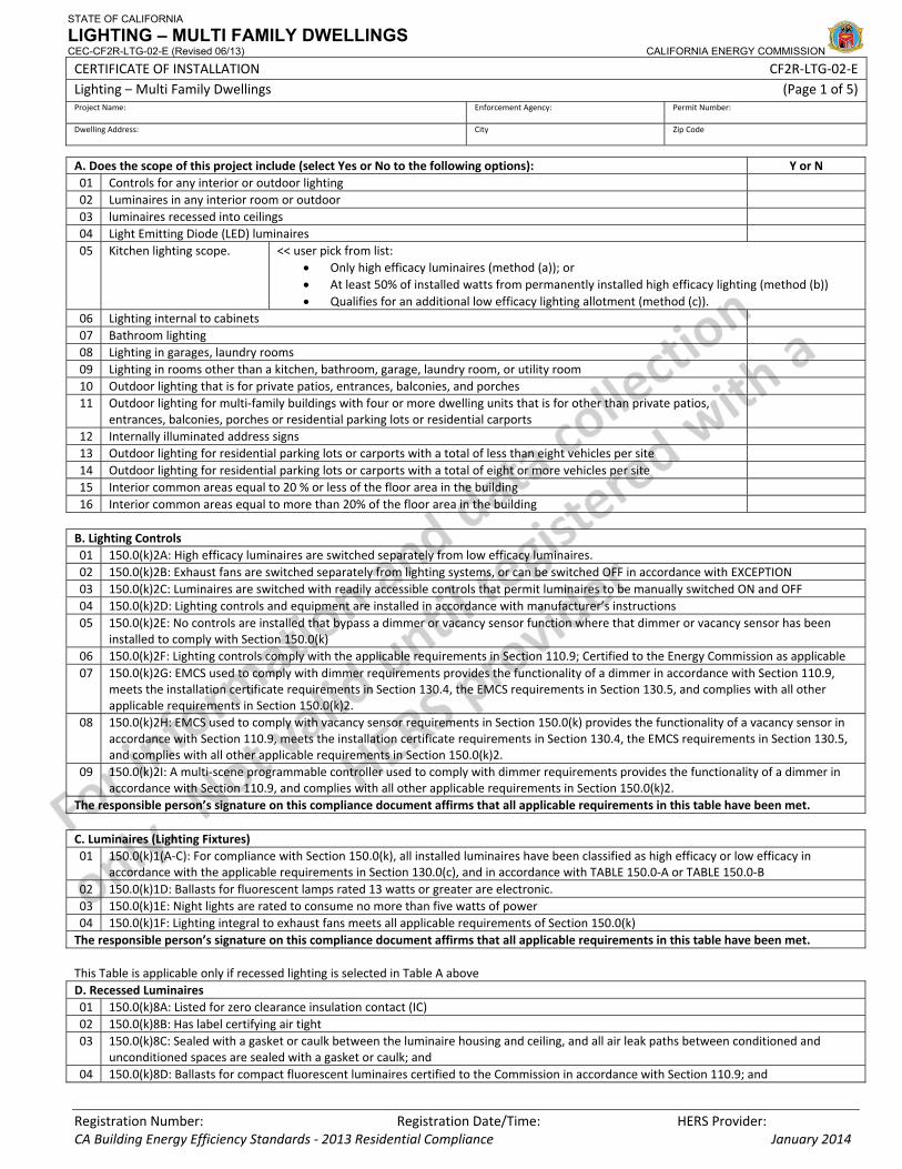
STATE OF CALIFORNIA
LIGHTING – MULTI FAMILY DWELLINGS CEC-CF2R-LTG-02-E (Revised 06/13) CALIFORNIA ENERGY COMMISSION
CERTIFICATE OF INSTALLATION CF2R‐LTG‐02‐E Lighting – Multi Family Dwellings (Page 1 of 5)Project Name: Enforcement Agency: Permit Number:
Dwelling Address: City Zip Code
Registration Number: Registration Date/Time: HERS Provider: CA Building Energy Efficiency Standards ‐ 2013 Residential Compliance January 2014
A. Does the scope of this project include (select Yes or No to the following options): Y or N 01 Controls for any interior or outdoor lighting 02 Luminaires in any interior room or outdoor 03 luminaires recessed into ceilings 04 Light Emitting Diode (LED) luminaires 05 Kitchen lighting scope. << user pick from list:
• Only high efficacy luminaires (method (a)); or • At least 50% of installed watts from permanently installed high efficacy lighting (method (b)) • Qualifies for an additional low efficacy lighting allotment (method (c)).
06 Lighting internal to cabinets 07 Bathroom lighting 08 Lighting in garages, laundry rooms 09 Lighting in rooms other than a kitchen, bathroom, garage, laundry room, or utility room 10 Outdoor lighting that is for private patios, entrances, balconies, and porches 11 Outdoor lighting for multi‐family buildings with four or more dwelling units that is for other than private patios,
entrances, balconies, porches or residential parking lots or residential carports
12 Internally illuminated address signs 13 Outdoor lighting for residential parking lots or carports with a total of less than eight vehicles per site 14 Outdoor lighting for residential parking lots or carports with a total of eight or more vehicles per site 15 Interior common areas equal to 20 % or less of the floor area in the building 16 Interior common areas equal to more than 20% of the floor area in the building B. Lighting Controls 01 150.0(k)2A: High efficacy luminaires are switched separately from low efficacy luminaires. 02 150.0(k)2B: Exhaust fans are switched separately from lighting systems, or can be switched OFF in accordance with EXCEPTION 03 150.0(k)2C: Luminaires are switched with readily accessible controls that permit luminaires to be manually switched ON and OFF 04 150.0(k)2D: Lighting controls and equipment are installed in accordance with manufacturer’s instructions 05 150.0(k)2E: No controls are installed that bypass a dimmer or vacancy sensor function where that dimmer or vacancy sensor has been
installed to comply with Section 150.0(k) 06 150.0(k)2F: Lighting controls comply with the applicable requirements in Section 110.9; Certified to the Energy Commission as applicable 07 150.0(k)2G: EMCS used to comply with dimmer requirements provides the functionality of a dimmer in accordance with Section 110.9,
meets the installation certificate requirements in Section 130.4, the EMCS requirements in Section 130.5, and complies with all other applicable requirements in Section 150.0(k)2.
08 150.0(k)2H: EMCS used to comply with vacancy sensor requirements in Section 150.0(k) provides the functionality of a vacancy sensor in accordance with Section 110.9, meets the installation certificate requirements in Section 130.4, the EMCS requirements in Section 130.5, and complies with all other applicable requirements in Section 150.0(k)2.
09 150.0(k)2I: A multi‐scene programmable controller used to comply with dimmer requirements provides the functionality of a dimmer in accordance with Section 110.9, and complies with all other applicable requirements in Section 150.0(k)2.
The responsible person’s signature on this compliance document affirms that all applicable requirements in this table have been met. C. Luminaires (Lighting Fixtures) 01 150.0(k)1(A‐C): For compliance with Section 150.0(k), all installed luminaires have been classified as high efficacy or low efficacy in
accordance with the applicable requirements in Section 130.0(c), and in accordance with TABLE 150.0‐A or TABLE 150.0‐B 02 150.0(k)1D: Ballasts for fluorescent lamps rated 13 watts or greater are electronic. 03 150.0(k)1E: Night lights are rated to consume no more than five watts of power 04 150.0(k)1F: Lighting integral to exhaust fans meets all applicable requirements of Section 150.0(k) The responsible person’s signature on this compliance document affirms that all applicable requirements in this table have been met. This Table is applicable only if recessed lighting is selected in Table A above D. Recessed Luminaires 01 150.0(k)8A: Listed for zero clearance insulation contact (IC) 02 150.0(k)8B: Has label certifying air tight 03 150.0(k)8C: Sealed with a gasket or caulk between the luminaire housing and ceiling, and all air leak paths between conditioned and
unconditioned spaces are sealed with a gasket or caulk; and 04 150.0(k)8D: Ballasts for compact fluorescent luminaires certified to the Commission in accordance with Section 110.9; and
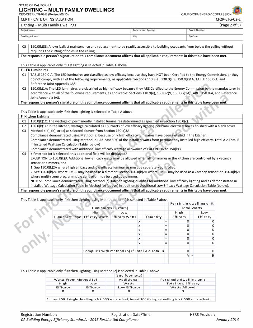
STATE OF CALIFORNIA
LIGHTING – MULTI FAMILY DWELLINGS CEC-CF2R-LTG-02-E (Revised 06/13) CALIFORNIA ENERGY COMMISSION
CERTIFICATE OF INSTALLATION CF2R‐LTG‐02‐E Lighting – Multi Family Dwellings (Page 2 of 5)Project Name: Enforcement Agency: Permit Number:
Dwelling Address: City Zip Code
Registration Number: Registration Date/Time: HERS Provider: CA Building Energy Efficiency Standards ‐ 2013 Residential Compliance January 2014
05 150.0(k)8E: Allows ballast maintenance and replacement to be readily accessible to building occupants from below the ceiling without requiring the cutting of holes in the ceiling.
The responsible person’s signature on this compliance document affirms that all applicable requirements in this table have been met. This Table is applicable only if LED lighting is selected in Table A above E. LED Luminaires 01 TABLE 150.0‐A: The LED luminaires are classified as low efficacy because they have NOT been Certified to the Energy Commission, or they
do not comply with all of the following requirements, as applicable: Sections 110.9(e), 130.0(c)9, 150.0(k)1A, TABLE 150.0‐A, and Reference Joint Appendix JA8.
02 150.0(k)1A: The LED luminaires are classified as high efficacy because they ARE Certified to the Energy Commission by the manufacturer in accordance with all of the following requirements, as applicable: Sections 110.9(e), 130.0(c)9, 150.0(k)1A, TABLE 150.0‐A, and Reference Joint Appendix JA8.
The responsible person’s signature on this compliance document affirms that all applicable requirements in this table have been met. This Table is applicable only if Kitchen lighting is selected in Table A above F. Kitchen Lighting 01 150.0(k)1C: The wattage of permanently installed luminaires determined as specified in Section 130.0(c). 02 150.0(k)1C: In the kitchen, wattage calculated as 180 watts of low efficacy lighting per blank electrical boxes finished with a blank cover. 03 Method <(a), (b), or (c) as selected above> from Section 150(k)3A:
Compliance demonstrated using Method (a) because only high efficacy luminaires have been installed in the kitchen. Compliance demonstrated using Method (b). At least 50% of the installed watts from permanently installed high efficacy. Total A ≥ Total B in Installed Wattage Calculation Table (below) Compliance demonstrated with additional low efficacy wattage allowance of EXCEPTION to 150(k)3
04 <If method (c) is selected, this additional field will be displayed> EXCEPTION to 150.0(k)3: Additional low efficacy watts may be allowed when all luminaires in the kitchen are controlled by a vacancy sensor or dimmers, and 1. See 150.0(k)2A where high efficacy and low efficacy luminaires must be separately controlled. 2. See 150.0(k)2G where EMCS may be used as a dimmer; Section 150.0(k)2H where EMCS may be used as a vacancy sensor; or, 150.0(k)2I where multi‐scene programmable controller may be used as a dimmer. NOTES: Compliance demonstrated using Method (c). Kitchen lighting qualifies for additional low efficacy lighting and as demonstrated in Installed Wattage Calculation Table in Method (b) (above) in addition to Additional Low Efficacy Wattage Calculation Table (below).
The responsible person’s signature on this compliance document affirms that all applicable requirements in this table have been met.
This Table is applicable only if Kitchen Lighting using Method (b) or (c) is selected in Table F above
High Low High LowLuminai re Type Efficacy Watts Efficacy Watts Quanti ty Effi cacy Effi cacy
x = 0x = 0x = 0x = 0x = 0x = 0
Compl ies with method (b) i f Tota l A ≥ Total B 0A >
000000
0B
Luminai res (Fixture) Total WattsPer s ingle dwel l ing uni t
This Table is applicable only if Kitchen Lighting using Method (c) is selected in Table F above
(see footnote)Additiona l Per s ingle dwel l ing unit
High Low Watts Tota l Low EfficacyEfficacy Efficacy Low Efficacy Watts Al lowd
0 0 0 0
1. Insert 50 if single dwelling is ≤ 2,500 square feet; Insert 100 if single dwelling is > 2,500 square feet.
Watts From Method (b)
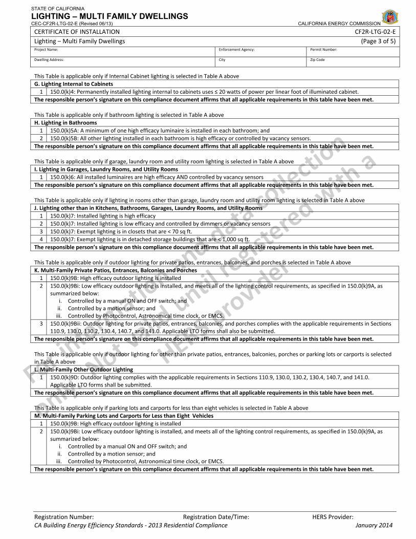
STATE OF CALIFORNIA
LIGHTING – MULTI FAMILY DWELLINGS CEC-CF2R-LTG-02-E (Revised 06/13) CALIFORNIA ENERGY COMMISSION
CERTIFICATE OF INSTALLATION CF2R‐LTG‐02‐E Lighting – Multi Family Dwellings (Page 3 of 5)Project Name: Enforcement Agency: Permit Number:
Dwelling Address: City Zip Code
Registration Number: Registration Date/Time: HERS Provider: CA Building Energy Efficiency Standards ‐ 2013 Residential Compliance January 2014
This Table is applicable only if Internal Cabinet lighting is selected in Table A above G. Lighting Internal to Cabinets 1 150.0(k)4: Permanently installed lighting internal to cabinets uses ≤ 20 watts of power per linear foot of illuminated cabinet.
The responsible person’s signature on this compliance document affirms that all applicable requirements in this table have been met. This Table is applicable only if bathroom lighting is selected in Table A above H. Lighting in Bathrooms 1 150.0(k)5A: A minimum of one high efficacy luminaire is installed in each bathroom; and 2 150.0(k)5B: All other lighting installed in each bathroom is high efficacy or controlled by vacancy sensors.
The responsible person’s signature on this compliance document affirms that all applicable requirements in this table have been met. This Table is applicable only if garage, laundry room and utility room lighting is selected in Table A above I. Lighting in Garages, Laundry Rooms, and Utility Rooms 1 150.0(k)6: All installed luminaires are high efficacy AND controlled by vacancy sensors
The responsible person’s signature on this compliance document affirms that all applicable requirements in this table have been met. This Table is applicable only if lighting in rooms other than garage, laundry room and utility room lighting is selected in Table A above J. Lighting other than in Kitchens, Bathrooms, Garages, Laundry Rooms, and Utility Rooms 1 150.0(k)7: Installed lighting is high efficacy 2 150.0(k)7: Installed lighting is low efficacy and controlled by dimmers or vacancy sensors 3 150.0(k)7: Exempt lighting is in closets that are < 70 sq ft. 4 150.0(k)7: Exempt lighting is in detached storage buildings that are < 1,000 sq ft.
The responsible person’s signature on this compliance document affirms that all applicable requirements in this table have been met. This Table is applicable only if outdoor lighting for private patios, entrances, balconies, and porches is selected in Table A above K. Multi‐Family Private Patios, Entrances, Balconies and Porches 1 150.0(k)9B: High efficacy outdoor lighting is installed 2 150.0(k)9Bi: Low efficacy outdoor lighting is installed, and meets all of the lighting control requirements, as specified in 150.0(k)9A, as
summarized below: i. Controlled by a manual ON and OFF switch; and ii. Controlled by a motion sensor; and iii. Controlled by Photocontrol, Astronomical time clock, or EMCS.
3 150.0(k)9Bii: Outdoor lighting for private patios, entrances, balconies, and porches complies with the applicable requirements in Sections 110.9, 130.0, 130.2, 130.4, 140.7, and 141.0. Applicable LTO forms shall also be submitted.
The responsible person’s signature on this compliance document affirms that all applicable requirements in this table have been met. This Table is applicable only if outdoor lighting for other than private patios, entrances, balconies, porches or parking lots or carports is selected in Table A above L. Multi‐Family Other Outdoor Lighting 1 150.0(k)9D: Outdoor lighting complies with the applicable requirements in Sections 110.9, 130.0, 130.2, 130.4, 140.7, and 141.0.
Applicable LTO forms shall be submitted. The responsible person’s signature on this compliance document affirms that all applicable requirements in this table have been met. This Table is applicable only if parking lots and carports for less than eight vehicles is selected in Table A above M. Multi‐Family Parking Lots and Carports for Less than Eight Vehicles 1 150.0(k)9B: High efficacy outdoor lighting is installed 2 150.0(k)9Bi: Low efficacy outdoor lighting is installed, and meets all of the lighting control requirements, as specified in 150.0(k)9A, as
summarized below: i. Controlled by a manual ON and OFF switch; and ii. Controlled by a motion sensor; and iii. Controlled by Photocontrol, Astronomical time clock, or EMCS.
The responsible person’s signature on this compliance document affirms that all applicable requirements in this table have been met.
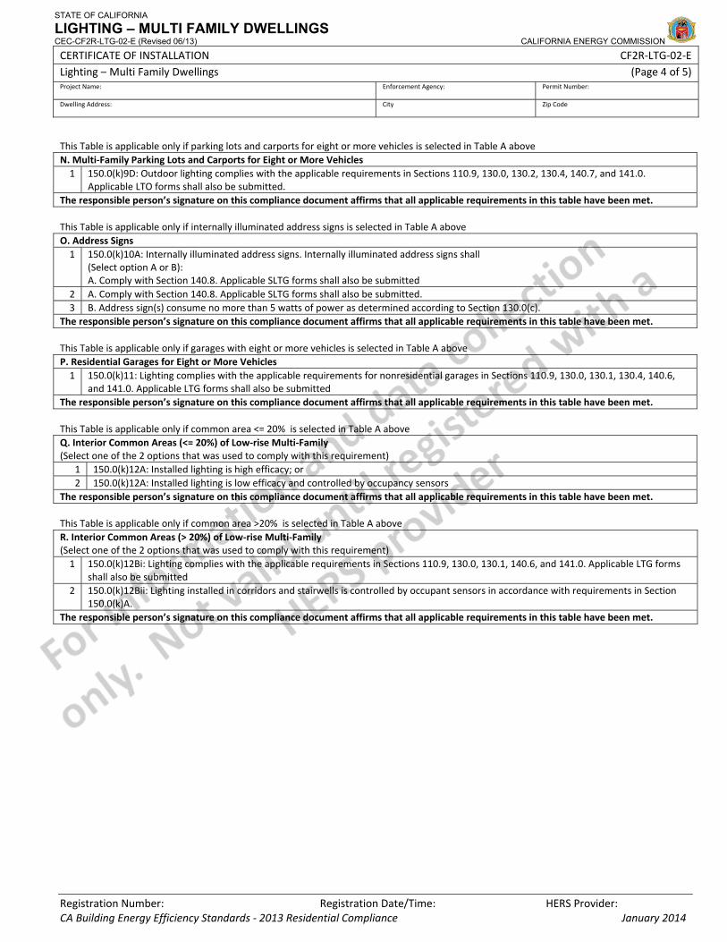
STATE OF CALIFORNIA
LIGHTING – MULTI FAMILY DWELLINGS CEC-CF2R-LTG-02-E (Revised 06/13) CALIFORNIA ENERGY COMMISSION
CERTIFICATE OF INSTALLATION CF2R‐LTG‐02‐E Lighting – Multi Family Dwellings (Page 4 of 5)Project Name: Enforcement Agency: Permit Number:
Dwelling Address: City Zip Code
Registration Number: Registration Date/Time: HERS Provider: CA Building Energy Efficiency Standards ‐ 2013 Residential Compliance January 2014
This Table is applicable only if parking lots and carports for eight or more vehicles is selected in Table A above N. Multi‐Family Parking Lots and Carports for Eight or More Vehicles 1 150.0(k)9D: Outdoor lighting complies with the applicable requirements in Sections 110.9, 130.0, 130.2, 130.4, 140.7, and 141.0.
Applicable LTO forms shall also be submitted. The responsible person’s signature on this compliance document affirms that all applicable requirements in this table have been met. This Table is applicable only if internally illuminated address signs is selected in Table A above O. Address Signs 1 150.0(k)10A: Internally illuminated address signs. Internally illuminated address signs shall
(Select option A or B): A. Comply with Section 140.8. Applicable SLTG forms shall also be submitted
2 A. Comply with Section 140.8. Applicable SLTG forms shall also be submitted. 3 B. Address sign(s) consume no more than 5 watts of power as determined according to Section 130.0(c).
The responsible person’s signature on this compliance document affirms that all applicable requirements in this table have been met. This Table is applicable only if garages with eight or more vehicles is selected in Table A above P. Residential Garages for Eight or More Vehicles 1 150.0(k)11: Lighting complies with the applicable requirements for nonresidential garages in Sections 110.9, 130.0, 130.1, 130.4, 140.6,
and 141.0. Applicable LTG forms shall also be submitted The responsible person’s signature on this compliance document affirms that all applicable requirements in this table have been met. This Table is applicable only if common area <= 20% is selected in Table A above Q. Interior Common Areas (<= 20%) of Low‐rise Multi‐Family (Select one of the 2 options that was used to comply with this requirement)
1 150.0(k)12A: Installed lighting is high efficacy; or 2 150.0(k)12A: Installed lighting is low efficacy and controlled by occupancy sensors
The responsible person’s signature on this compliance document affirms that all applicable requirements in this table have been met. This Table is applicable only if common area >20% is selected in Table A above R. Interior Common Areas (> 20%) of Low‐rise Multi‐Family (Select one of the 2 options that was used to comply with this requirement) 1 150.0(k)12Bi: Lighting complies with the applicable requirements in Sections 110.9, 130.0, 130.1, 140.6, and 141.0. Applicable LTG forms
shall also be submitted 2 150.0(k)12Bii: Lighting installed in corridors and stairwells is controlled by occupant sensors in accordance with requirements in Section
150.0(k)A. The responsible person’s signature on this compliance document affirms that all applicable requirements in this table have been met.
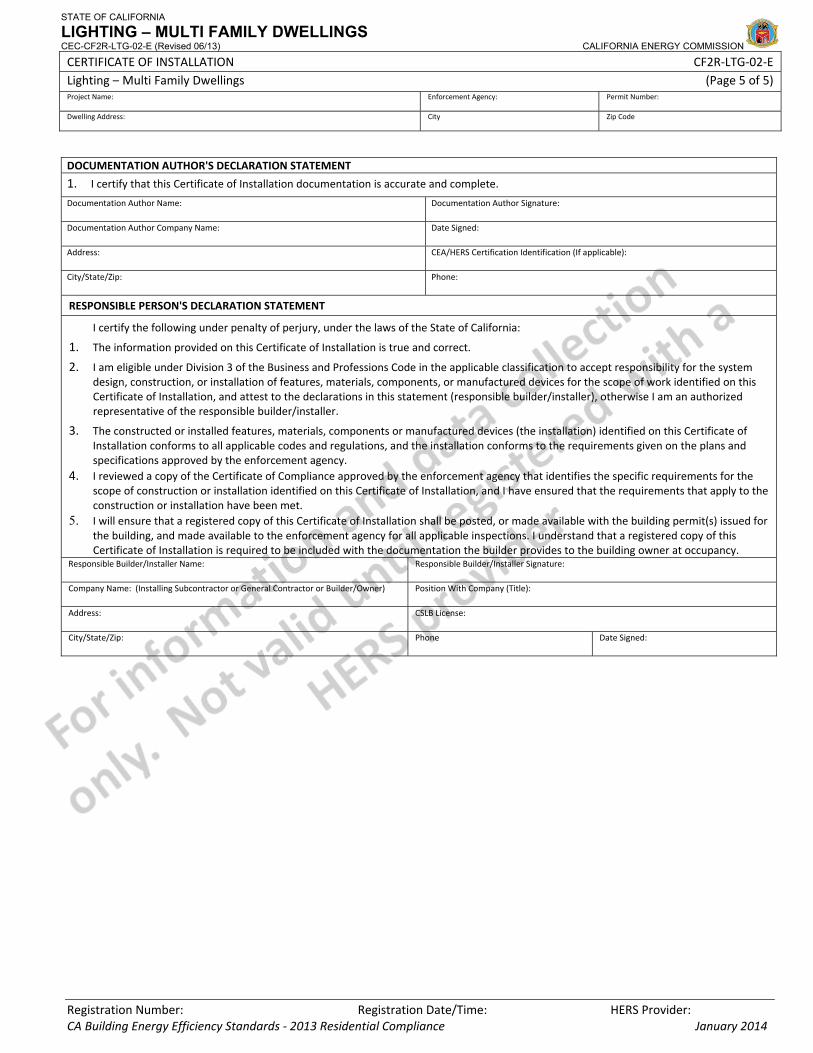
STATE OF CALIFORNIA
LIGHTING – MULTI FAMILY DWELLINGS CEC-CF2R-LTG-02-E (Revised 06/13) CALIFORNIA ENERGY COMMISSION
CERTIFICATE OF INSTALLATION CF2R‐LTG‐02‐E Lighting – Multi Family Dwellings (Page 5 of 5)Project Name: Enforcement Agency: Permit Number:
Dwelling Address: City Zip Code
Registration Number: Registration Date/Time: HERS Provider: CA Building Energy Efficiency Standards ‐ 2013 Residential Compliance January 2014
DOCUMENTATION AUTHOR'S DECLARATION STATEMENT
1. I certify that this Certificate of Installation documentation is accurate and complete.
Documentation Author Name: Documentation Author Signature:
Documentation Author Company Name: Date Signed:
Address: CEA/HERS Certification Identification (If applicable):
City/State/Zip: Phone:
RESPONSIBLE PERSON'S DECLARATION STATEMENT
I certify the following under penalty of perjury, under the laws of the State of California:
1. The information provided on this Certificate of Installation is true and correct.
2. I am eligible under Division 3 of the Business and Professions Code in the applicable classification to accept responsibility for the system design, construction, or installation of features, materials, components, or manufactured devices for the scope of work identified on this Certificate of Installation, and attest to the declarations in this statement (responsible builder/installer), otherwise I am an authorized representative of the responsible builder/installer.
3. The constructed or installed features, materials, components or manufactured devices (the installation) identified on this Certificate of Installation conforms to all applicable codes and regulations, and the installation conforms to the requirements given on the plans and specifications approved by the enforcement agency.
4. I reviewed a copy of the Certificate of Compliance approved by the enforcement agency that identifies the specific requirements for the scope of construction or installation identified on this Certificate of Installation, and I have ensured that the requirements that apply to the construction or installation have been met.
5. I will ensure that a registered copy of this Certificate of Installation shall be posted, or made available with the building permit(s) issued for the building, and made available to the enforcement agency for all applicable inspections. I understand that a registered copy of this Certificate of Installation is required to be included with the documentation the builder provides to the building owner at occupancy.
Responsible Builder/Installer Name: Responsible Builder/Installer Signature:
Company Name: (Installing Subcontractor or General Contractor or Builder/Owner) Position With Company (Title):
Address: CSLB License:
City/State/Zip: Phone Date Signed:
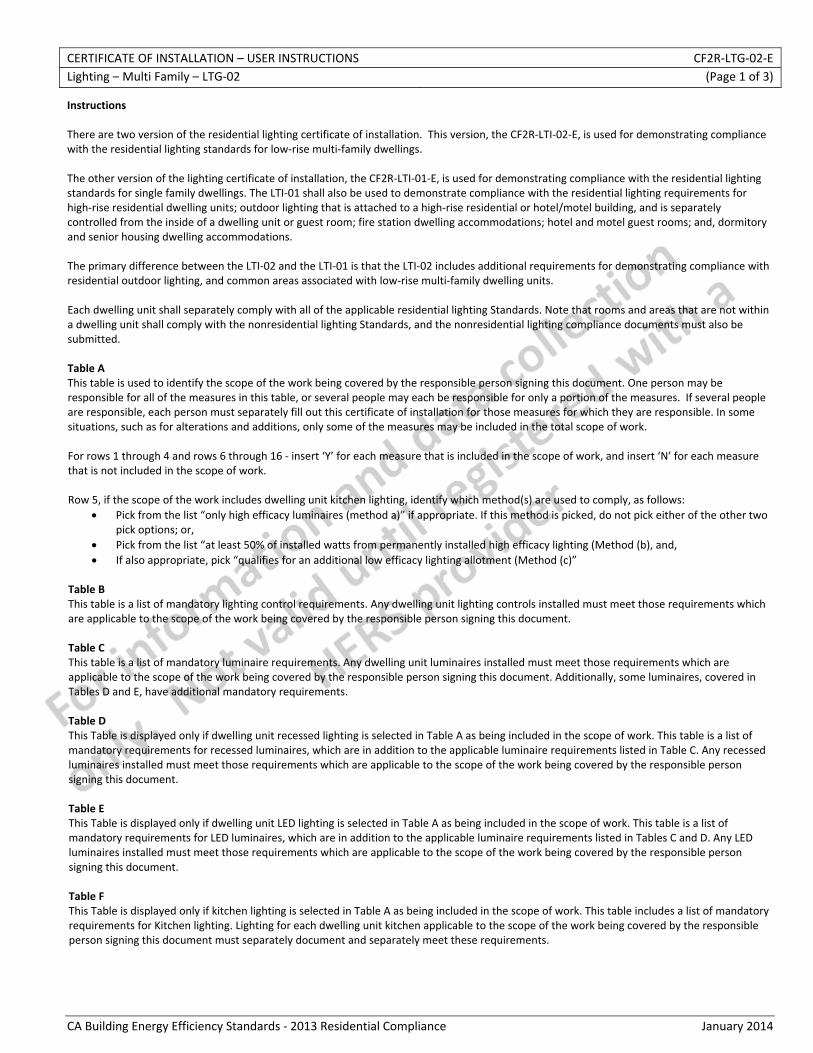
CERTIFICATE OF INSTALLATION – USER INSTRUCTIONS CF2R‐LTG‐02‐E Lighting – Multi Family – LTG‐02 (Page 1 of 3)
CA Building Energy Efficiency Standards ‐ 2013 Residential Compliance January 2014
Instructions There are two version of the residential lighting certificate of installation. This version, the CF2R‐LTI‐02‐E, is used for demonstrating compliance with the residential lighting standards for low‐rise multi‐family dwellings. The other version of the lighting certificate of installation, the CF2R‐LTI‐01‐E, is used for demonstrating compliance with the residential lighting standards for single family dwellings. The LTI‐01 shall also be used to demonstrate compliance with the residential lighting requirements for high‐rise residential dwelling units; outdoor lighting that is attached to a high‐rise residential or hotel/motel building, and is separately controlled from the inside of a dwelling unit or guest room; fire station dwelling accommodations; hotel and motel guest rooms; and, dormitory and senior housing dwelling accommodations. The primary difference between the LTI‐02 and the LTI‐01 is that the LTI‐02 includes additional requirements for demonstrating compliance with residential outdoor lighting, and common areas associated with low‐rise multi‐family dwelling units. Each dwelling unit shall separately comply with all of the applicable residential lighting Standards. Note that rooms and areas that are not within a dwelling unit shall comply with the nonresidential lighting Standards, and the nonresidential lighting compliance documents must also be submitted. Table A This table is used to identify the scope of the work being covered by the responsible person signing this document. One person may be responsible for all of the measures in this table, or several people may each be responsible for only a portion of the measures. If several people are responsible, each person must separately fill out this certificate of installation for those measures for which they are responsible. In some situations, such as for alterations and additions, only some of the measures may be included in the total scope of work. For rows 1 through 4 and rows 6 through 16 ‐ insert ‘Y’ for each measure that is included in the scope of work, and insert ‘N’ for each measure that is not included in the scope of work. Row 5, if the scope of the work includes dwelling unit kitchen lighting, identify which method(s) are used to comply, as follows:
• Pick from the list “only high efficacy luminaires (method a)” if appropriate. If this method is picked, do not pick either of the other two pick options; or,
• Pick from the list “at least 50% of installed watts from permanently installed high efficacy lighting (Method (b), and, • If also appropriate, pick “qualifies for an additional low efficacy lighting allotment (Method (c)”
Table B This table is a list of mandatory lighting control requirements. Any dwelling unit lighting controls installed must meet those requirements which are applicable to the scope of the work being covered by the responsible person signing this document. Table C This table is a list of mandatory luminaire requirements. Any dwelling unit luminaires installed must meet those requirements which are applicable to the scope of the work being covered by the responsible person signing this document. Additionally, some luminaires, covered in Tables D and E, have additional mandatory requirements. Table D This Table is displayed only if dwelling unit recessed lighting is selected in Table A as being included in the scope of work. This table is a list of mandatory requirements for recessed luminaires, which are in addition to the applicable luminaire requirements listed in Table C. Any recessed luminaires installed must meet those requirements which are applicable to the scope of the work being covered by the responsible person signing this document. Table E This Table is displayed only if dwelling unit LED lighting is selected in Table A as being included in the scope of work. This table is a list of mandatory requirements for LED luminaires, which are in addition to the applicable luminaire requirements listed in Tables C and D. Any LED luminaires installed must meet those requirements which are applicable to the scope of the work being covered by the responsible person signing this document. Table F This Table is displayed only if kitchen lighting is selected in Table A as being included in the scope of work. This table includes a list of mandatory requirements for Kitchen lighting. Lighting for each dwelling unit kitchen applicable to the scope of the work being covered by the responsible person signing this document must separately document and separately meet these requirements.
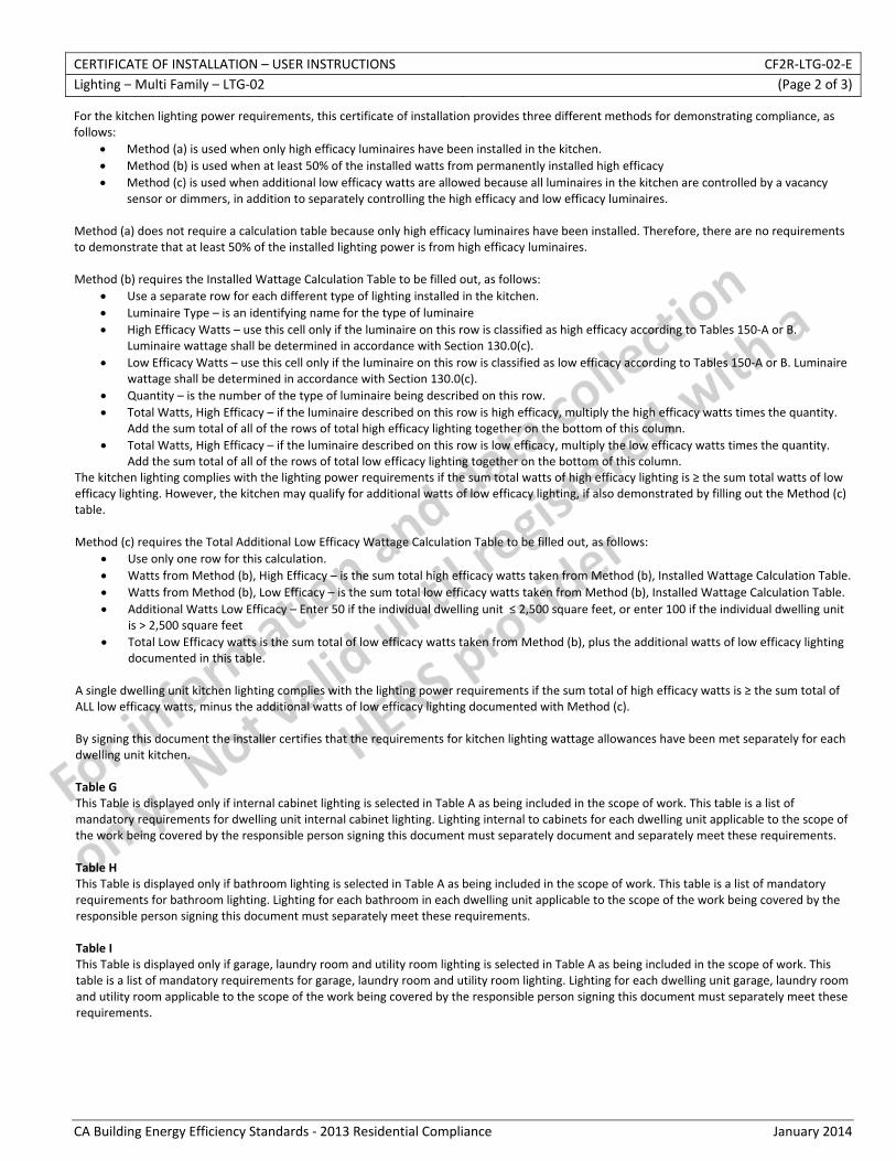
CERTIFICATE OF INSTALLATION – USER INSTRUCTIONS CF2R‐LTG‐02‐E Lighting – Multi Family – LTG‐02 (Page 2 of 3)
CA Building Energy Efficiency Standards ‐ 2013 Residential Compliance January 2014
For the kitchen lighting power requirements, this certificate of installation provides three different methods for demonstrating compliance, as follows:
• Method (a) is used when only high efficacy luminaires have been installed in the kitchen. • Method (b) is used when at least 50% of the installed watts from permanently installed high efficacy • Method (c) is used when additional low efficacy watts are allowed because all luminaires in the kitchen are controlled by a vacancy
sensor or dimmers, in addition to separately controlling the high efficacy and low efficacy luminaires. Method (a) does not require a calculation table because only high efficacy luminaires have been installed. Therefore, there are no requirements to demonstrate that at least 50% of the installed lighting power is from high efficacy luminaires. Method (b) requires the Installed Wattage Calculation Table to be filled out, as follows:
• Use a separate row for each different type of lighting installed in the kitchen. • Luminaire Type – is an identifying name for the type of luminaire • High Efficacy Watts – use this cell only if the luminaire on this row is classified as high efficacy according to Tables 150‐A or B.
Luminaire wattage shall be determined in accordance with Section 130.0(c). • Low Efficacy Watts – use this cell only if the luminaire on this row is classified as low efficacy according to Tables 150‐A or B. Luminaire
wattage shall be determined in accordance with Section 130.0(c). • Quantity – is the number of the type of luminaire being described on this row. • Total Watts, High Efficacy – if the luminaire described on this row is high efficacy, multiply the high efficacy watts times the quantity.
Add the sum total of all of the rows of total high efficacy lighting together on the bottom of this column. • Total Watts, High Efficacy – if the luminaire described on this row is low efficacy, multiply the low efficacy watts times the quantity.
Add the sum total of all of the rows of total low efficacy lighting together on the bottom of this column. The kitchen lighting complies with the lighting power requirements if the sum total watts of high efficacy lighting is ≥ the sum total watts of low efficacy lighting. However, the kitchen may qualify for additional watts of low efficacy lighting, if also demonstrated by filling out the Method (c) table. Method (c) requires the Total Additional Low Efficacy Wattage Calculation Table to be filled out, as follows:
• Use only one row for this calculation. • Watts from Method (b), High Efficacy – is the sum total high efficacy watts taken from Method (b), Installed Wattage Calculation Table. • Watts from Method (b), Low Efficacy – is the sum total low efficacy watts taken from Method (b), Installed Wattage Calculation Table. • Additional Watts Low Efficacy – Enter 50 if the individual dwelling unit ≤ 2,500 square feet, or enter 100 if the individual dwelling unit
is > 2,500 square feet • Total Low Efficacy watts is the sum total of low efficacy watts taken from Method (b), plus the additional watts of low efficacy lighting
documented in this table. A single dwelling unit kitchen lighting complies with the lighting power requirements if the sum total of high efficacy watts is ≥ the sum total of ALL low efficacy watts, minus the additional watts of low efficacy lighting documented with Method (c). By signing this document the installer certifies that the requirements for kitchen lighting wattage allowances have been met separately for each dwelling unit kitchen. Table G This Table is displayed only if internal cabinet lighting is selected in Table A as being included in the scope of work. This table is a list of mandatory requirements for dwelling unit internal cabinet lighting. Lighting internal to cabinets for each dwelling unit applicable to the scope of the work being covered by the responsible person signing this document must separately document and separately meet these requirements. Table H This Table is displayed only if bathroom lighting is selected in Table A as being included in the scope of work. This table is a list of mandatory requirements for bathroom lighting. Lighting for each bathroom in each dwelling unit applicable to the scope of the work being covered by the responsible person signing this document must separately meet these requirements. Table I This Table is displayed only if garage, laundry room and utility room lighting is selected in Table A as being included in the scope of work. This table is a list of mandatory requirements for garage, laundry room and utility room lighting. Lighting for each dwelling unit garage, laundry room and utility room applicable to the scope of the work being covered by the responsible person signing this document must separately meet these requirements.
CERTIFICATE OF INSTALLATION – USER INSTRUCTIONS CF2R‐LTG‐02‐E Lighting – Multi Family – LTG‐02 (Page 3 of 3)
CA Building Energy Efficiency Standards ‐ 2013 Residential Compliance January 2014
Table J This Table is displayed only if lighting in rooms other than garage, laundry room and utility room is selected in Table A as being included in the scope of work. This table is a list of mandatory requirements for lighting in dwelling unit rooms other than garage, laundry room and utility room. These mandatory requirements apply to any dwelling unit room not defined in Section 100.1 of the Standards as a residential garage, residential laundry room or residential utility room. Lighting for each dwelling unit room that is other than a garage, laundry room or utility room utility room applicable to the scope of the work being covered by the responsible person signing this document must separately meet these requirements. Table K This Table is displayed only if outdoor lighting for private patios, entrances, balconies, and porches is selected in Table A as being included in the scope of work. This table is a list of mandatory requirements for outdoor lighting for private patios, entrances, balconies, and porches. Outdoor lighting for each dwelling applicable to the scope of the work being covered by the responsible person signing this document must separately meet these requirements. If the nonresidential lighting standards are used to comply with the outdoor lighting for private patios, entrances, balconies, and porches, then the nonresidential outdoor lighting compliance documents must also be submitted. Table L This Table is displayed only if outdoor lighting for other than private patios, entrances, balconies, and porches is selected in Table A as being included in the scope of work. This table is a list of sections in the Standards required for compliance with outdoor lighting for low rise multi‐family outdoor lighting which is other than private patios, entrances, balconies, and porches. Outdoor lighting applicable to the scope of the work being covered by the responsible person signing this document must separately meet these requirements. The nonresidential outdoor lighting compliance documents must also be submitted. Table M This Table is displayed only if lighting for parking lots and carports for less than eight vehicles is selected in Table A as being included in the scope of work. This table is a list of mandatory requirements for parking lots and carports for less than eight vehicles. Outdoor lighting applicable to the scope of the work being covered by the responsible person signing this document must meet these requirements. Table N This Table is displayed only if lighting for parking lots and carports for eight of more vehicles is selected in Table A as being included in the scope of work. This Table applies when the site has a combined sum total of eight of more vehicles for all parking lots and carports. This table is a list of sections in the Standards required for compliance with outdoor lighting for low rise multi‐family outdoor lighting for parking lots and carports for eight of more vehicles lighting. Outdoor lighting applicable to the scope of the work being covered by the responsible person signing this document must meet these requirements. The nonresidential outdoor lighting compliance documents must also be submitted. Table O This Table is displayed only if internally illuminated address signs is selected in Table A as being included in the scope of work. This table is a list of mandatory requirements for internally illuminated address signs. Lighting for each internally illuminated address sign applicable to the scope of the work being covered by the responsible person signing this document must separately meet these requirements. Table P This Table is displayed only if lighting for garages with eight or more vehicles is selected in Table A as being included in the scope of work. This table is a list of sections in the Standards required for compliance with lighting for garages with eight or more vehicles. Lighting applicable to the scope of the work being covered by the responsible person signing this document must meet these requirements. The nonresidential indoor lighting compliance documents must also be submitted. Table Q This Table is displayed only if lighting for common areas ≤ 20% is selected in Table A as being included in the scope of work. This table is a list of mandatory requirements when common areas ≤ 20% of the area of a single building. Lighting for the common areas of each building must be separately documented. Lighting applicable to the scope of the work being covered by the responsible person signing this document must meet these requirements. Table R This Table is displayed only if lighting for common areas > 20% is selected in Table A as being included in the scope of work. This Table applies when a single building has a combined total of > 20% common area (areas which do not qualify as residential individual dwelling unit areas). Each building shall be separately documented. This table is a list of sections in the Standards required for compliance with indoor lighting of common areas of low rise multi‐family. Lighting applicable to the scope of the work being covered by the responsible person signing this document must meet these requirements. The nonresidential indoor lighting compliance documents must also be submitted.

CERTIFICATE OF INSTALLATION – DATA FIELD DEFINITIONS AND CALCULATIONS CF2R‐LTG‐02‐E Lighting – Multi Family – LTG‐02 (Page 1 of 5)
CA Building Energy Efficiency Standards ‐ 2013 Residential Compliance January 2014
A. Does the scope of this project include (select Yes or No to the following options): Y or N 1 Controls for any interior or outdoor lighting 2 Luminaires in any interior room or outdoor 3 luminaires recessed into ceilings 4 Light Emitting Diode (LED) luminaires 5 Kitchen lighting scope. << user pick from list:
• only high efficacy luminaires (method a); or • at least 50% of installed watts from permanently installed high efficacy lighting (Method (b)) • qualifies for an additional low efficacy lighting allotment (Method (c))>>
6 Lighting internal to cabinets 7 Bathroom lighting 8 Lighting in garages, laundry rooms 9 Lighting in rooms other than a kitchen, bathroom, garage, laundry room, or utility room 10 Outdoor lighting that is for private patios, entrances, balconies, and porches 11 Outdoor lighting for multi‐family buildings with four or more dwelling units that is for other than private patios, entrances,
balconies, porches or residential parking lots or residential carports
12 Internally illuminated address signs 13 Outdoor lighting for residential parking lots or carports with a total of less than eight vehicles per site 14 Outdoor lighting for residential parking lots or carports with a total of eight or more vehicles per site 15 Interior common areas equal to 20 % or less of the floor area in the building 16 Interior common areas equal to more than 20% of the floor area in the building B. Lighting Controls 1 150.0(k)2A: High efficacy luminaires are switched separately from low efficacy luminaires. 2 150.0(k)2B: Exhaust fans are switched separately from lighting systems, or can be switched OFF in accordance with EXCEPTION 3 150.0(k)2C: Luminaires are switched with readily accessible controls that permit luminaires to be manually switched ON and OFF 4 150.0(k)2D: Lighting controls and equipment are installed in accordance with manufacturer’s instructions 5 150.0(k)2E: No controls are installed that bypass a dimmer or vacancy sensor function where that dimmer or vacancy sensor has been
installed to comply with Section 150.0(k) 6 150.0(k)2F: Lighting controls comply with the applicable requirements in Section 110.9; Certified to the Energy Commission as applicable 7 150.0(k)2G: EMCS used to comply with dimmer requirements provides the functionality of a dimmer in accordance with Section 110.9,
meets the installation certificate requirements in Section 130.4, the EMCS requirements in Section 130.5, and complies with all other applicable requirements in Section 150.0(k)2.
8 150.0(k)2H: EMCS used to comply with vacancy sensor requirements in Section 150.0(k) provides the functionality of a vacancy sensor in accordance with Section 110.9, meets the installation certificate requirements in Section 130.4, the EMCS requirements in Section 130.5, and complies with all other applicable requirements in Section 150.0(k)2.
9 150.0(k)2I: A multi‐scene programmable controller used to comply with dimmer requirements provides the functionality of a dimmer in accordance with Section 110.9, and complies with all other applicable requirements in Section 150.0(k)2.
The responsible person’s signature on this compliance document affirms that all applicable requirements in this table have been met. C. Luminaires (Lighting Fixtures) 1 150.0(k)1(A‐C): For compliance with Section 150.0(k), all installed luminaires have been classified as high efficacy or low efficacy in
accordance with the applicable requirements in Section 130.0(c), and in accordance with TABLE 150.0‐A or TABLE 150.0‐B 2 150.0(k)1D: Ballasts for fluorescent lamps rated 13 watts or greater are electronic. 3 150.0(k)1E: Night lights are rated to consume no more than five watts of power 4 150.0(k)1F: Lighting integral to exhaust fans meets all applicable requirements of Section 150.0(k)
The responsible person’s signature on this compliance document affirms that all applicable requirements in this table have been met.
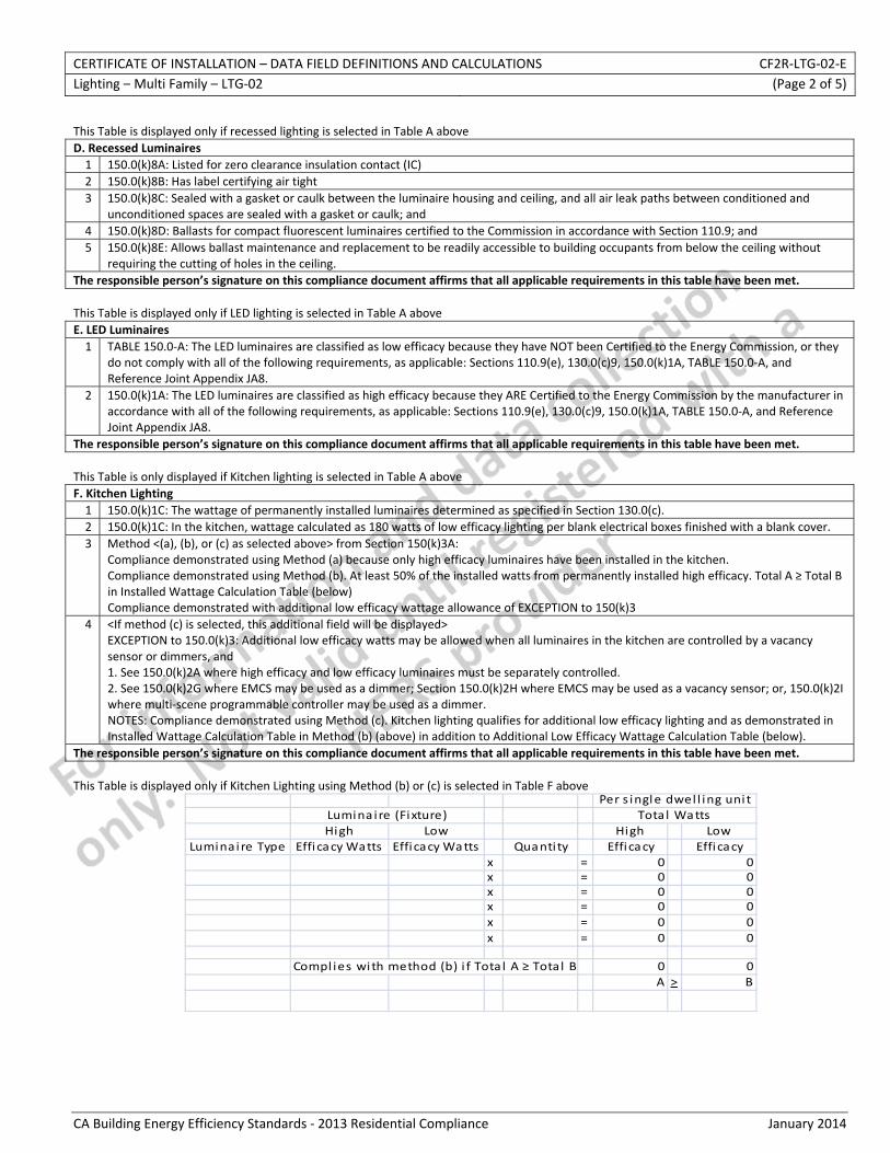
CERTIFICATE OF INSTALLATION – DATA FIELD DEFINITIONS AND CALCULATIONS CF2R‐LTG‐02‐E Lighting – Multi Family – LTG‐02 (Page 2 of 5)
CA Building Energy Efficiency Standards ‐ 2013 Residential Compliance January 2014
This Table is displayed only if recessed lighting is selected in Table A above D. Recessed Luminaires 1 150.0(k)8A: Listed for zero clearance insulation contact (IC) 2 150.0(k)8B: Has label certifying air tight 3 150.0(k)8C: Sealed with a gasket or caulk between the luminaire housing and ceiling, and all air leak paths between conditioned and
unconditioned spaces are sealed with a gasket or caulk; and 4 150.0(k)8D: Ballasts for compact fluorescent luminaires certified to the Commission in accordance with Section 110.9; and 5 150.0(k)8E: Allows ballast maintenance and replacement to be readily accessible to building occupants from below the ceiling without
requiring the cutting of holes in the ceiling. The responsible person’s signature on this compliance document affirms that all applicable requirements in this table have been met. This Table is displayed only if LED lighting is selected in Table A above E. LED Luminaires 1 TABLE 150.0‐A: The LED luminaires are classified as low efficacy because they have NOT been Certified to the Energy Commission, or they
do not comply with all of the following requirements, as applicable: Sections 110.9(e), 130.0(c)9, 150.0(k)1A, TABLE 150.0‐A, and Reference Joint Appendix JA8.
2 150.0(k)1A: The LED luminaires are classified as high efficacy because they ARE Certified to the Energy Commission by the manufacturer in accordance with all of the following requirements, as applicable: Sections 110.9(e), 130.0(c)9, 150.0(k)1A, TABLE 150.0‐A, and Reference Joint Appendix JA8.
The responsible person’s signature on this compliance document affirms that all applicable requirements in this table have been met. This Table is only displayed if Kitchen lighting is selected in Table A above F. Kitchen Lighting 1 150.0(k)1C: The wattage of permanently installed luminaires determined as specified in Section 130.0(c). 2 150.0(k)1C: In the kitchen, wattage calculated as 180 watts of low efficacy lighting per blank electrical boxes finished with a blank cover. 3 Method <(a), (b), or (c) as selected above> from Section 150(k)3A:
Compliance demonstrated using Method (a) because only high efficacy luminaires have been installed in the kitchen. Compliance demonstrated using Method (b). At least 50% of the installed watts from permanently installed high efficacy. Total A ≥ Total B in Installed Wattage Calculation Table (below) Compliance demonstrated with additional low efficacy wattage allowance of EXCEPTION to 150(k)3
4 <If method (c) is selected, this additional field will be displayed> EXCEPTION to 150.0(k)3: Additional low efficacy watts may be allowed when all luminaires in the kitchen are controlled by a vacancy sensor or dimmers, and 1. See 150.0(k)2A where high efficacy and low efficacy luminaires must be separately controlled. 2. See 150.0(k)2G where EMCS may be used as a dimmer; Section 150.0(k)2H where EMCS may be used as a vacancy sensor; or, 150.0(k)2I where multi‐scene programmable controller may be used as a dimmer. NOTES: Compliance demonstrated using Method (c). Kitchen lighting qualifies for additional low efficacy lighting and as demonstrated in Installed Wattage Calculation Table in Method (b) (above) in addition to Additional Low Efficacy Wattage Calculation Table (below).
The responsible person’s signature on this compliance document affirms that all applicable requirements in this table have been met.
This Table is displayed only if Kitchen Lighting using Method (b) or (c) is selected in Table F above
High Low High LowLuminai re Type Efficacy Watts Efficacy Watts Quanti ty Effi cacy Effi cacy
x = 0x = 0x = 0x = 0x = 0x = 0
Compl ies with method (b) i f Tota l A ≥ Total B 0A >
000000
0B
Lumina ire (Fixture) Total WattsPer s ingle dwel l ing uni t
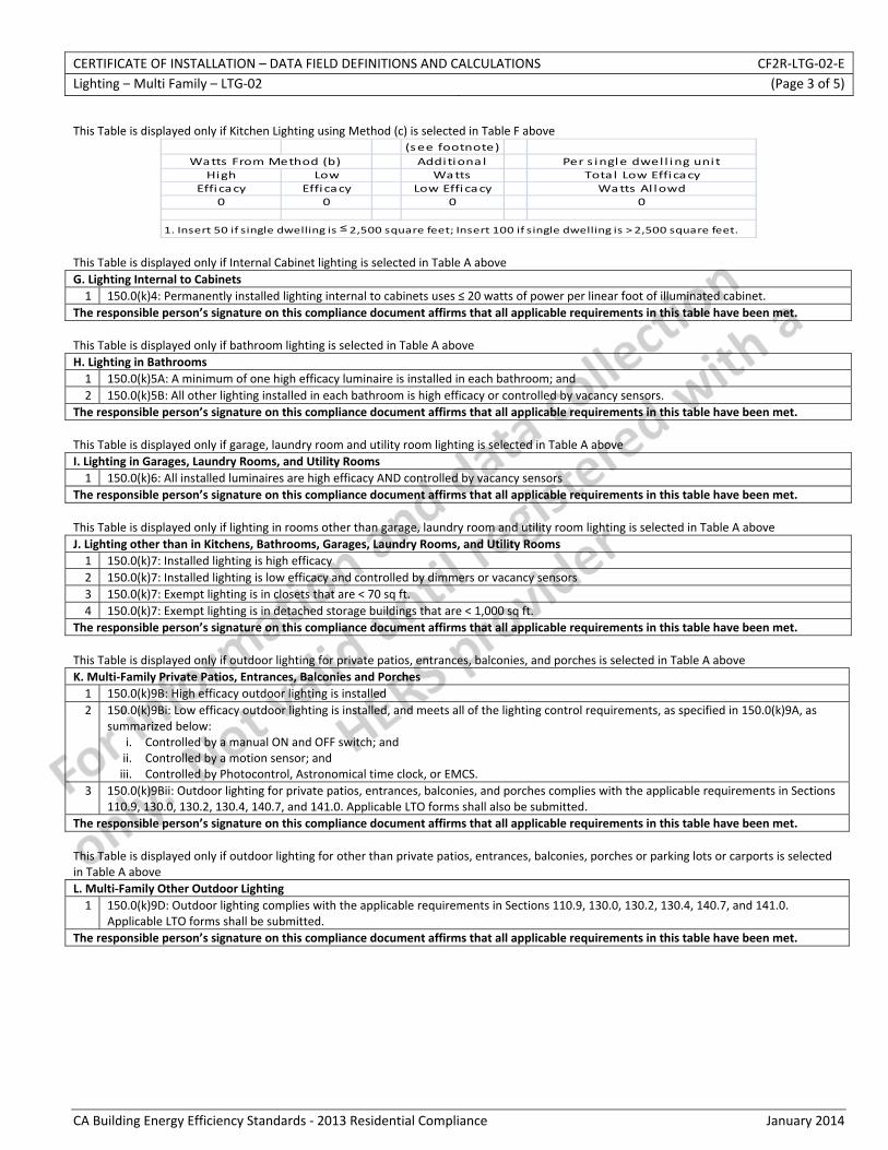
CERTIFICATE OF INSTALLATION – DATA FIELD DEFINITIONS AND CALCULATIONS CF2R‐LTG‐02‐E Lighting – Multi Family – LTG‐02 (Page 3 of 5)
CA Building Energy Efficiency Standards ‐ 2013 Residential Compliance January 2014
This Table is displayed only if Kitchen Lighting using Method (c) is selected in Table F above
(see footnote)Additiona l Per s ingle dwel l ing unit
High Low Watts Tota l Low EfficacyEfficacy Efficacy Low Efficacy Watts Al lowd
0 0 0 0
1. Insert 50 if single dwelling is ≤ 2,500 square feet; Insert 100 if single dwelling is > 2,500 square feet.
Watts From Method (b)
This Table is displayed only if Internal Cabinet lighting is selected in Table A above G. Lighting Internal to Cabinets 1 150.0(k)4: Permanently installed lighting internal to cabinets uses ≤ 20 watts of power per linear foot of illuminated cabinet.
The responsible person’s signature on this compliance document affirms that all applicable requirements in this table have been met. This Table is displayed only if bathroom lighting is selected in Table A above H. Lighting in Bathrooms 1 150.0(k)5A: A minimum of one high efficacy luminaire is installed in each bathroom; and 2 150.0(k)5B: All other lighting installed in each bathroom is high efficacy or controlled by vacancy sensors.
The responsible person’s signature on this compliance document affirms that all applicable requirements in this table have been met. This Table is displayed only if garage, laundry room and utility room lighting is selected in Table A above I. Lighting in Garages, Laundry Rooms, and Utility Rooms 1 150.0(k)6: All installed luminaires are high efficacy AND controlled by vacancy sensors
The responsible person’s signature on this compliance document affirms that all applicable requirements in this table have been met. This Table is displayed only if lighting in rooms other than garage, laundry room and utility room lighting is selected in Table A above J. Lighting other than in Kitchens, Bathrooms, Garages, Laundry Rooms, and Utility Rooms 1 150.0(k)7: Installed lighting is high efficacy 2 150.0(k)7: Installed lighting is low efficacy and controlled by dimmers or vacancy sensors 3 150.0(k)7: Exempt lighting is in closets that are < 70 sq ft. 4 150.0(k)7: Exempt lighting is in detached storage buildings that are < 1,000 sq ft.
The responsible person’s signature on this compliance document affirms that all applicable requirements in this table have been met. This Table is displayed only if outdoor lighting for private patios, entrances, balconies, and porches is selected in Table A above K. Multi‐Family Private Patios, Entrances, Balconies and Porches 1 150.0(k)9B: High efficacy outdoor lighting is installed 2 150.0(k)9Bi: Low efficacy outdoor lighting is installed, and meets all of the lighting control requirements, as specified in 150.0(k)9A, as
summarized below: i. Controlled by a manual ON and OFF switch; and ii. Controlled by a motion sensor; and iii. Controlled by Photocontrol, Astronomical time clock, or EMCS.
3 150.0(k)9Bii: Outdoor lighting for private patios, entrances, balconies, and porches complies with the applicable requirements in Sections 110.9, 130.0, 130.2, 130.4, 140.7, and 141.0. Applicable LTO forms shall also be submitted.
The responsible person’s signature on this compliance document affirms that all applicable requirements in this table have been met. This Table is displayed only if outdoor lighting for other than private patios, entrances, balconies, porches or parking lots or carports is selected in Table A above L. Multi‐Family Other Outdoor Lighting 1 150.0(k)9D: Outdoor lighting complies with the applicable requirements in Sections 110.9, 130.0, 130.2, 130.4, 140.7, and 141.0.
Applicable LTO forms shall be submitted. The responsible person’s signature on this compliance document affirms that all applicable requirements in this table have been met.

CERTIFICATE OF INSTALLATION – DATA FIELD DEFINITIONS AND CALCULATIONS CF2R‐LTG‐02‐E Lighting – Multi Family – LTG‐02 (Page 4 of 5)
CA Building Energy Efficiency Standards ‐ 2013 Residential Compliance January 2014
This Table is displayed only if parking lots and carports for less than eight vehicles is selected in Table A above M. Multi‐Family Parking Lots and Carports for Less than Eight Vehicles 01 150.0(k)9B: High efficacy outdoor lighting is installed
02 150.0(k)9Bi: Low efficacy outdoor lighting is installed, and meets all of the lighting control requirements, as specified in 150.0(k)9A, as summarized below: i. Controlled by a manual ON and OFF switch; and ii. Controlled by a motion sensor; and iii. Controlled by Photocontrol, Astronomical time clock, or EMCS.
The responsible person’s signature on this compliance document affirms that all applicable requirements in this table have been met. This Table is displayed only if parking lots and carports for eight or more vehicles is selected in Table A above N. Multi‐Family Parking Lots and Carports for Eight or More Vehicles 01 150.0(k)9D: Outdoor lighting complies with the applicable requirements in Sections 110.9, 130.0, 130.2, 130.4, 140.7, and 141.0.
Applicable LTO forms shall also be submitted. The responsible person’s signature on this compliance document affirms that all applicable requirements in this table have been met. This Table is displayed only if internally illuminated address signs is selected in Table A above O. Address Signs 01 150.0(k)10A: Internally illuminated address signs. Internally illuminated address signs shall
(Select option A or B): A. Comply with Section 140.8. Applicable SLTG forms shall also be submitted
02 A. Comply with Section 140.8. Applicable SLTG forms shall also be submitted. 03 B. Address sign(s) consume no more than 5 watts of power as determined according to Section 130.0(c). The responsible person’s signature on this compliance document affirms that all applicable requirements in this table have been met. This Table is displayed only if garages with eight or more vehicles is selected in Table A above P. Residential Garages for Eight or More Vehicles 01 150.0(k)11: Lighting complies with the applicable requirements for nonresidential garages in Sections 110.9, 130.0, 130.1, 130.4, 140.6,
and 141.0. Applicable LTG forms shall also be submitted The responsible person’s signature on this compliance document affirms that all applicable requirements in this table have been met. This Table is displayed only if common area <= 20% is selected in Table A above Q. Interior Common Areas (<= 20%) of Low‐rise Multi‐Family (Select one of the 2 options that was used to comply with this requirement) 01 150.0(k)12A: Installed lighting is high efficacy; or 02 150.0(k)12A: Installed lighting is low efficacy and controlled by occupancy sensors
The responsible person’s signature on this compliance document affirms that all applicable requirements in this table have been met. This Table is displayed only if common area >20% is selected in Table A above R. Interior Common Areas (> 20%) of Low‐rise Multi‐Family (Select one of the 2 options that was used to comply with this requirement) 01 150.0(k)12Bi: Lighting complies with the applicable requirements in Sections 110.9, 130.0, 130.1, 140.6, and 141.0. Applicable LTG forms
shall also be submitted 02 150.0(k)12Bii: Lighting installed in corridors and stairwells is controlled by occupant sensors in accordance with requirements in Section
150.0(k)A. The responsible person’s signature on this compliance document affirms that all applicable requirements in this table have been met.
CERTIFICATE OF INSTALLATION – DATA FIELD DEFINITIONS AND CALCULATIONS CF2R‐LTG‐02‐E Lighting – Multi Family – LTG‐02 (Page 5 of 5)
CA Building Energy Efficiency Standards ‐ 2013 Residential Compliance January 2014
DOCUMENTATION AUTHOR'S DECLARATION STATEMENT
1. I certify that this Certificate of Installation documentation is accurate and complete.
Documentation Author Name: Documentation Author Signature:
Documentation Author Company Name: Date Signed:
Address: CEA/CEPE/HERS certification identification (If applicable):
City/State/Zip: Phone:
RESPONSIBLE PERSON'S DECLARATION STATEMENT
I certify the following under penalty of perjury, under the laws of the State of California:
1. The information provided on this Certificate of Installation is true and correct.
2. I am eligible under Division 3 of the Business and Professions Code to accept responsibility for the scope of construction or installation, in the applicable classification, for the scope of work specified on this Certificate of Installation (responsible builder/installer), otherwise I am an authorized representative of the responsible builder/installer.
3. The constructed or installed features, materials, components or manufactured devices (the installation) identified on this Certificate of Installation conforms to all applicable codes and regulations, and the installation conforms to the requirements given on the plans and specifications approved by the enforcement agency.
4. I reviewed a copy of the Certificate of Compliance approved by the enforcement agency that identifies the specific requirements for the scope of construction or installation identified on this Certificate of Installation, and I have ensured that the requirements that apply to the construction or installation have been met.
5. I will ensure that a registered copy of this Certificate of Installation shall be posted, or made available with the building permit(s) issued for the building, and made available to the enforcement agency for all applicable inspections. I understand that a registered copy of this Certificate of Installation is required to be included with the documentation the builder provides to the building owner at occupancy.
Responsible Builder/Installer Name: Responsible Builder/Installer Signature:
Company Name: (Installing Subcontractor or General Contractor or Builder/Owner) Position With Company (Title):
Address: CSLB License:
City/State/Zip: Phone Date Signed:
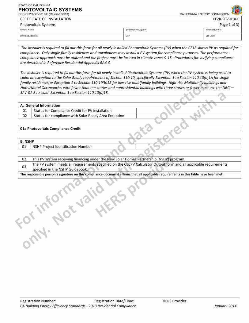
STATE OF CALIFORNIA
PHOTOVOLTAIC SYSTEMS CEC-CF2R-SPV-01a-E (Revised 06/13) CALIFORNIA ENERGY COMMISSION
CERTIFICATE OF INSTALLATION CF2R‐SPV‐01a‐E Photovoltaic Systems (Page 1 of 3) Project Name: Enforcement Agency: Permit Number:
Dwelling Address: City Zip Code
Registration Number: Registration Date/Time: HERS Provider: CA Building Energy Efficiency Standards ‐ 2013 Residential Compliance January 2014
The installer is required to fill out this form for all newly installed Photovoltaic Systems (PV) when the CF1R shows PV as required for compliance. Only single family residences and townhouses may install a PV system for compliance purposes. The performance compliance approach must be utilized and the project must be located in climate zones 9‐15. Procedures for verifying compliance are described in Reference Residential Appendix RA4.6. The installer is required to fill out this form for all newly installed Photovoltaic Systems (PV) when the PV system is being used to claim an exception to the Solar Ready requirements of Section 110.10, specifically Exception 1 to Section 110.10(b)1A for single family residences or Exception 1 to Section 110.10(b)1B for low‐rise multifamily buildings. High‐rise Multifamily buildings and Hotel/Motel Occupancies with fewer than ten stories and nonresidential buildings with three stories or fewer must use the NRCI—SPV‐01‐E to claim Exception 1 to Section 110.10(b)1B.
A. General Information 01 Status for Compliance Credit for PV installation02 Status for compliance with Solar Ready Area Exception
01a Photovoltaic Compliance Credit
B. NSHP 01 NSHP Project Identification Number
02 This PV system receiving financing under the New Solar Homes Partnership (NSHP) program.
03 The PV system meets all requirements specified on the CECPV Calculator Output form and all applicable requirements specified in the NSHP Guidebook.
The responsible person’s signature on this compliance document affirms that all applicable requirements in this table have been met.
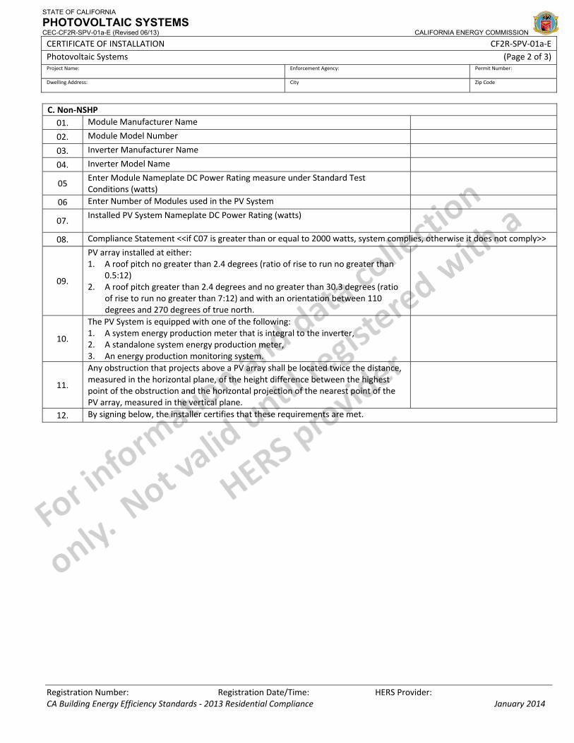
STATE OF CALIFORNIA
PHOTOVOLTAIC SYSTEMS CEC-CF2R-SPV-01a-E (Revised 06/13) CALIFORNIA ENERGY COMMISSION
CERTIFICATE OF INSTALLATION CF2R‐SPV‐01a‐E Photovoltaic Systems (Page 2 of 3) Project Name: Enforcement Agency: Permit Number:
Dwelling Address: City Zip Code
Registration Number: Registration Date/Time: HERS Provider: CA Building Energy Efficiency Standards ‐ 2013 Residential Compliance January 2014
C. Non‐NSHP 01. Module Manufacturer Name
02. Module Model Number
03. Inverter Manufacturer Name
04. Inverter Model Name
05 Enter Module Nameplate DC Power Rating measure under Standard Test Conditions (watts)
06 Enter Number of Modules used in the PV System
07. Installed PV System Nameplate DC Power Rating (watts)
08. Compliance Statement <<if C07 is greater than or equal to 2000 watts, system complies, otherwise it does not comply>>
09.
PV array installed at either: 1. A roof pitch no greater than 2.4 degrees (ratio of rise to run no greater than
0.5:12) 2. A roof pitch greater than 2.4 degrees and no greater than 30.3 degrees (ratio
of rise to run no greater than 7:12) and with an orientation between 110 degrees and 270 degrees of true north.
10.
The PV System is equipped with one of the following: 1. A system energy production meter that is integral to the inverter, 2. A standalone system energy production meter, 3. An energy production monitoring system.
11.
Any obstruction that projects above a PV array shall be located twice the distance, measured in the horizontal plane, of the height difference between the highest point of the obstruction and the horizontal projection of the nearest point of the PV array, measured in the vertical plane.
12. By signing below, the installer certifies that these requirements are met.
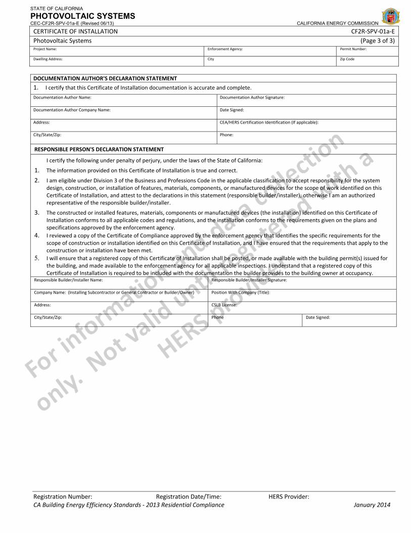
STATE OF CALIFORNIA
PHOTOVOLTAIC SYSTEMS CEC-CF2R-SPV-01a-E (Revised 06/13) CALIFORNIA ENERGY COMMISSION
CERTIFICATE OF INSTALLATION CF2R‐SPV‐01a‐E Photovoltaic Systems (Page 3 of 3) Project Name: Enforcement Agency: Permit Number:
Dwelling Address: City Zip Code
Registration Number: Registration Date/Time: HERS Provider: CA Building Energy Efficiency Standards ‐ 2013 Residential Compliance January 2014
DOCUMENTATION AUTHOR'S DECLARATION STATEMENT
1. I certify that this Certificate of Installation documentation is accurate and complete.
Documentation Author Name: Documentation Author Signature:
Documentation Author Company Name: Date Signed:
Address: CEA/HERS Certification Identification (If applicable):
City/State/Zip: Phone:
RESPONSIBLE PERSON'S DECLARATION STATEMENT
I certify the following under penalty of perjury, under the laws of the State of California:
1. The information provided on this Certificate of Installation is true and correct.
2. I am eligible under Division 3 of the Business and Professions Code in the applicable classification to accept responsibility for the system design, construction, or installation of features, materials, components, or manufactured devices for the scope of work identified on this Certificate of Installation, and attest to the declarations in this statement (responsible builder/installer), otherwise I am an authorized representative of the responsible builder/installer.
3. The constructed or installed features, materials, components or manufactured devices (the installation) identified on this Certificate of Installation conforms to all applicable codes and regulations, and the installation conforms to the requirements given on the plans and specifications approved by the enforcement agency.
4. I reviewed a copy of the Certificate of Compliance approved by the enforcement agency that identifies the specific requirements for the scope of construction or installation identified on this Certificate of Installation, and I have ensured that the requirements that apply to the construction or installation have been met.
5. I will ensure that a registered copy of this Certificate of Installation shall be posted, or made available with the building permit(s) issued for the building, and made available to the enforcement agency for all applicable inspections. I understand that a registered copy of this Certificate of Installation is required to be included with the documentation the builder provides to the building owner at occupancy.
Responsible Builder/Installer Name: Responsible Builder/Installer Signature:
Company Name: (Installing Subcontractor or General Contractor or Builder/Owner) Position With Company (Title):
Address: CSLB License:
City/State/Zip: Phone Date Signed:
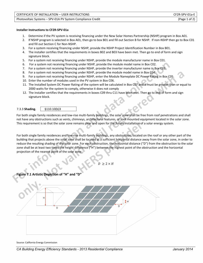
CERTIFICATE OF INSTALLATION – USER INSTRUCTIONS CF2R‐SPV‐01a‐E Photovoltaic Systems – SPV‐01A PV System Compliance Credit (Page 1 of 2)
CA Building Energy Efficiency Standards - 2013 Residential Compliance January 2014
Installer Instructions to CF2R‐SPV‐01a
1. Determine if the PV system is receiving financing under the New Solar Homes Partnership (NSHP) program in Box A01. 2. If NSHP program is selected in Box A01, then go to box B01 and fill out Section B for NSHP. If non‐NSHP then go to Box C01
and fill out Section C for Non‐NSHP. 3. For a system receiving financing under NSHP, provide the NSHP Project Identification Number in Box B01. 4. The installer certifies that the requirements in boxes B02 and B03 have been met. Then go to end of form and sign
signature block. 5. For a system not receiving financing under NSHP, provide the module manufacturer name in Box C01. 6. For a system not receiving financing under NSHP, provide the module model name in Box C02. 7. For a system not receiving financing under NSHP, provide the inverter manufacturer name in Box C03. 8. For a system not receiving financing under NSHP, provide the module model name in Box C04. 9. For a system not receiving financing under NSHP, enter the Module Nameplate DC Power Rating in Box C05. 10. Enter the number of modules used in the PV system in Box C06. 11. The Installed System DC Power Rating of the system will be calculated in Box C07 and it must be greater than or equal to
2000 watts for the system to comply, otherwise it does not comply 12. The installer certifies that the requirements in boxes C09 thru C11 have been met. Then go to end of form and sign
signature block.
7.3.3 Shading. §110.10(b)3
For both single family residences and low‐rise multi‐family buildings, the solar zone shall be free from roof penetrations and shall not have any obstructions such as vents, chimneys, architectural features, or roof mounted equipment located in the solar zone. This requirement is so that the solar zone remains clear and open for the future installation of a solar energy system.
For both single family residences and low‐rise multi‐family buildings, any obstruction, located on the roof or any other part of the building that projects above the solar zone shall be located at a sufficient horizontal distance away from the solar zone, in order to reduce the resulting shading of the solar zone. For each obstruction, the horizontal distance (“D”) from the obstruction to the solar zone shall be at least two times the height difference (“H”) between the highest point of the obstruction and the horizontal projection of the nearest point of the solar zone.
2
Figure 7.1 Artistic Depiction of “H” and “D”
Source: California Energy Commission
H
DD
H
CERTIFICATE OF INSTALLATION – USER INSTRUCTIONS CF2R‐SPV‐01a‐E Photovoltaic Systems – SPV‐01A PV System Compliance Credit (Page 2 of 2)
CA Building Energy Efficiency Standards - 2013 Residential Compliance January 2014
Any obstruction oriented north of all points of the solar zone is not subject to these requirements. Any obstruction which is not located on the roof or another part of the building, such as landscaping or a neighboring building is not subject to these requirements.
STATE OF CALIFORNIA
PHOTOVOLTAIC SYSTEM VERFICATION CEC-CF2R-SPV-01-E (Revised 06/13) CALIFORNIA ENERGY COMMISSION
CERTIFICATE OF INSTALLATION CF2R‐SPV‐01‐E Photovoltaic System Verification (Page 1 of 2) Project Name: Enforcement Agency: Permit Number:
Dwelling Address: City Zip Code
Registration Number: Registration Date/Time: HERS Provider: CA Building Energy Efficiency Standards ‐ 2013 Residential Compliance January 2014
The installer is required to fill out this form for all newly installed Photovoltaic Systems (PV) when the CF1R shows PV as required for compliance. Only single family residences and townhouses may install a PV system for compliance purposes. The performance compliance approach must be utilized and the project must be located in climate zones 9‐15. Procedures for verifying compliance are described in Reference Residential Appendix RA4.6. The installer is required to fill out this form for all newly installed Photovoltaic Systems (PV) when the PV system is being used to claim an exception to the Solar Ready requirements of Section 110.10, specifically Exception 1 to Section 110.10(b)1A for single family residences or Exception 1 to Section 110.10(b)1B for low‐rise multifamily buildings. High‐rise Multifamily buildings and Hotel/Motel Occupancies with fewer than ten stories and nonresidential buildings with three stories or fewer must use the NRCI—SPV‐01‐E to claim Exception 1 to Section 110.10(b)1B. A. General Information 01 Status for Compliance Credit for PV installation02 Status for compliance with Solar Ready Area Exception
01b Solar Exception to Solar Ready Area requirements
B. Single Family Residence
01 Enter Module Manufacturer Name
02 Enter Module Model Number
03 Enter Module nameplate DC Power Rating measure under Standard Test Conditions (watts)
04 Enter Number of Modules used in the PV System
05. Installed PV System Nameplate DC Power Rating (watts)
06. Compliance Statement:
C. Low‐rise Multifamily 01. Total Roof Area (ft2)
02. Minimum Nameplate DC Power Rating (Watts) = Total Roof Area (ft2) x (1 Watt/ft2)
03 Enter Module Manufacturer Name
04 Enter Module Model Number
05 Enter Module nameplate DC Power Rating measure under Standard Test Conditions (watts)
06 Enter Number of Modules used in the PV System
07. Installed PV System Nameplate DC Power Rating (watts)
08 Compliance Statement:

STATE OF CALIFORNIA
PHOTOVOLTAIC SYSTEM VERFICATION CEC-CF2R-SPV-01-E (Revised 06/13) CALIFORNIA ENERGY COMMISSION
CERTIFICATE OF INSTALLATION CF2R‐SPV‐01‐E Photovoltaic System Verification (Page 2 of 2) Project Name: Enforcement Agency: Permit Number:
Dwelling Address: City Zip Code
Registration Number: Registration Date/Time: HERS Provider: CA Building Energy Efficiency Standards ‐ 2013 Residential Compliance January 2014
DOCUMENTATION AUTHOR'S DECLARATION STATEMENT
1. I certify that this Certificate of Installation documentation is accurate and complete.
Documentation Author Name: Documentation Author Signature:
Documentation Author Company Name: Date Signed:
Address: CEA/HERS Certification Identification (If applicable):
City/State/Zip: Phone:
RESPONSIBLE PERSON'S DECLARATION STATEMENT
I certify the following under penalty of perjury, under the laws of the State of California:
1. The information provided on this Certificate of Installation is true and correct.
2. I am eligible under Division 3 of the Business and Professions Code in the applicable classification to accept responsibility for the system design, construction, or installation of features, materials, components, or manufactured devices for the scope of work identified on this Certificate of Installation, and attest to the declarations in this statement (responsible builder/installer), otherwise I am an authorized representative of the responsible builder/installer.
3. The constructed or installed features, materials, components or manufactured devices (the installation) identified on this Certificate of Installation conforms to all applicable codes and regulations, and the installation conforms to the requirements given on the plans and specifications approved by the enforcement agency.
4. I reviewed a copy of the Certificate of Compliance approved by the enforcement agency that identifies the specific requirements for the scope of construction or installation identified on this Certificate of Installation, and I have ensured that the requirements that apply to the construction or installation have been met.
5. I will ensure that a registered copy of this Certificate of Installation shall be posted, or made available with the building permit(s) issued for the building, and made available to the enforcement agency for all applicable inspections. I understand that a registered copy of this Certificate of Installation is required to be included with the documentation the builder provides to the building owner at occupancy.
Responsible Builder/Installer Name: Responsible Builder/Installer Signature:
Company Name: (Installing Subcontractor or General Contractor or Builder/Owner) Position With Company (Title):
Address: CSLB License:
City/State/Zip: Phone Date Signed:
CERTIFICATE OF INSTALLATION – USER INSTRUCTIONS CF2R‐SPV‐01‐E Photovoltaic Systems – CF2R‐SPV‐01b Exceptions to Solar Ready Area Requirements (Page 1 of 1)
Registration Number: Registration Date/Time: HERS Provider: CA Building Energy Efficiency Standards ‐ 2013 Residential Compliance January 2014
Installer Instructions
1. If “For Exception to Solar Ready Requirements in Section 110.10” is selected, then complete Section E by selecting either “Single Family Residence” or “Low‐rise Multifamily Building”
2. In Box A02, determine if project is single family or multifamily. 3. If Box A02 is single family, complete Section B. 4. If Single Family is selected, provide module manufacturer name in Box B01. 5. If Single Family is selected, provide module model name in Box B02. 6. If Single Family is selected, provide module nameplate DC power rating (watts) in Box B03. 7. If Single Family is selected, provide the number of modules use in the PV system in Box B04. 8. The Installed System DC Power Rating of the system will be calculated in Box B05 and it must be greater than or equal to
1000 watts. 9. The installer certifies that all requirements have been met. Then go to end of form and sign signature block 10. If Box E01 is Low‐rise Multifamily, complete Section C 11. If Low‐rise Multifamily is selected then go to Box C01 and provide the total roof area in square feet. 12. If Low‐rise Multifamily is selected, provide module manufacturer name in Box C03. 13. If Low‐rise Multifamily is selected, provide module model name in Box C04. 14. If Low‐rise Multifamily is selected, provide module nameplate DC power rating (watts) in Box C05. 15. If Low‐rise Multifamily is selected, provide the number of modules use in the PV system in Box C06. 16. The Installed System DC Power Rating of the system will be calculated in Box B05 and it must be greater than or equal to
the value in Box C02. The installer certifies that all requirements have been met. Then go to end of form and sign signature block
CERTIFICATE OF INSTALLATION – DATA FIELD DEFINITIONS AND CALCULATIONS CF2R‐SPV‐01‐E Photovoltaic Systems – CF2R‐SPV‐01b Exceptions to Solar Ready Area Requirements (Page 3 of 3)
Registration Number: Registration Date/Time: HERS Provider: CA Building Energy Efficiency Standards ‐ 2013 Residential Compliance January 2014
DOCUMENTATION AUTHOR'S DECLARATION STATEMENT
1. I certify that this Certificate of Installation documentation is accurate and complete.
Documentation Author Name: Documentation Author Signature:
Documentation Author Company Name: Date Signed:
Address: CEA/CEPE/HERS certification identification (If applicable):
City/State/Zip: Phone:
RESPONSIBLE PERSON'S DECLARATION STATEMENT
I certify the following under penalty of perjury, under the laws of the State of California:
1. The information provided on this Certificate of Installation is true and correct.
2. I am eligible under Division 3 of the Business and Professions Code to accept responsibility for the scope of construction or installation, in the applicable classification, for the scope of work specified on this Certificate of Installation (responsible builder/installer), otherwise I am an authorized representative of the responsible builder/installer.
3. The constructed or installed features, materials, components or manufactured devices (the installation) identified on this Certificate of Installation conforms to all applicable codes and regulations, and the installation conforms to the requirements given on the plans and specifications approved by the enforcement agency.
4. I reviewed a copy of the Certificate of Compliance approved by the enforcement agency that identifies the specific requirements for the scope of construction or installation identified on this Certificate of Installation, and I have ensured that the requirements that apply to the construction or installation have been met.
5. I will ensure that a registered copy of this Certificate of Installation shall be posted, or made available with the building permit(s) issued for the building, and made available to the enforcement agency for all applicable inspections. I understand that a registered copy of this Certificate of Installation is required to be included with the documentation the builder provides to the building owner at occupancy.
Responsible Builder/Installer Name: Responsible Builder/Installer Signature:
Company Name: (Installing Subcontractor or General Contractor or Builder/Owner) Position With Company (Title):
Address: CSLB License:
City/State/Zip: Phone Date Signed:
STATE OF CALIFORNIA PHOTOVOLTAIC SYSTEM VERIFICATION CEC-CF2R-SPV-01c-E (Revised 06/13) CALIFORNIA ENERGY COMMISSION
CERTIFICATE OF INSTALLATION CF2R‐SPV‐01c‐E Photovoltaic System Verification (Page 1 of 2) Project Name: Enforcement Agency: Permit Number:
Dwelling Address: City Zip Code
Registration Number: Registration Date/Time: HERS Provider: CA Building Energy Efficiency Standards ‐ 2013 Residential Compliance January 2014
The installer is required to fill out this form for all newly installed Photovoltaic Systems (PV) when the CF1R shows PV as required for compliance. Only single family residences and townhouses may install a PV system for compliance purposes. The performance compliance approach must be utilized and the project must be located in climate zones 9‐15. Procedures for verifying compliance are described in Reference Residential Appendix RA4.6. The installer is required to fill out this form for all newly installed Photovoltaic Systems (PV) when the PV system is being used to claim an exception to the Solar Ready requirements of Section 110.10, specifically Exception 1 to Section 110.10(b)1A for single family residences or Exception 1 to Section 110.10(b)1B for low‐rise multifamily buildings. High‐rise Multifamily buildings and Hotel/Motel Occupancies with fewer than ten stories and nonresidential buildings with three stories or fewer must use the NRCI—SPV‐01‐E to claim Exception 1 to Section 110.10(b)1B.
A. General Information 01 Status for Compliance Credit for PV installation02 Status for compliance with Solar Ready Area Exception
01c PV Compliance Credits + Exceptions to SRA requirements B. Single Family Residence 01 Enter Module Manufacturer Name
02 Enter Module Model Number
03 Enter Module nameplate DC Power Rating measured under Standard Test Conditions (watts)
04 Enter Number of Modules used in the PV System
05. Installed PV System Nameplate DC Power Rating (watts) C. NSHP 01 NSHP Project Identification Number
02 This PV system receiving financing under the New Solar Homes Partnership (NSHP) program.
03 The PV system meets all requirements specified on the CECPV Calculator Output form and all applicable requirements specified in the NSHP Guidebook.
The responsible person’s signature on this compliance document affirms that all applicable requirements in this table have been met.
D. Non‐NSHP 01. Inverter Manufacturer Name
02. Inverter Model Name
03. Compliance Statement:
STATE OF CALIFORNIA PHOTOVOLTAIC SYSTEM VERIFICATION CEC-CF2R-SPV-01c-E (Revised 06/13) CALIFORNIA ENERGY COMMISSION
CERTIFICATE OF INSTALLATION CF2R‐SPV‐01c‐E Photovoltaic System Verification (Page 2 of 2) Project Name: Enforcement Agency: Permit Number:
Dwelling Address: City Zip Code
Registration Number: Registration Date/Time: HERS Provider: CA Building Energy Efficiency Standards ‐ 2013 Residential Compliance January 2014
04.
PV array installed at either: • A roof pitch no greater than 2.4 degrees (ratio of rise to run no greater than 0.5:12) • A roof pitch greater than 2.4 degrees and no greater than 30.3 degrees (ratio of rise to run no greater than 7:12) and
with an orientation between 110 degrees and 270 degrees of true north.
05.
The PV System is equipped with one of the following: • A system energy production meter that is integral to the inverter, • A standalone system energy production meter, • An energy production monitoring system.
06. Any obstruction that projects above a PV array shall be located twice the distance, measured in the horizontal plane, of the height difference between the highest point of the obstruction and the horizontal projection of the nearest point of the PV array, measured in the vertical plane.
The responsible person’s signature on this compliance document affirms that all applicable requirements in this table have been met.
DOCUMENTATION AUTHOR'S DECLARATION STATEMENT
1. I certify that this Certificate of Installation documentation is accurate and complete.
Documentation Author Name: Documentation Author Signature:
Documentation Author Company Name: Date Signed:
Address: CEA/HERS Certification Identification (If applicable):
City/State/Zip: Phone:
RESPONSIBLE PERSON'S DECLARATION STATEMENT
I certify the following under penalty of perjury, under the laws of the State of California:
1. The information provided on this Certificate of Installation is true and correct.
2. I am eligible under Division 3 of the Business and Professions Code in the applicable classification to accept responsibility for the system design, construction, or installation of features, materials, components, or manufactured devices for the scope of work identified on this Certificate of Installation, and attest to the declarations in this statement (responsible builder/installer), otherwise I am an authorized representative of the responsible builder/installer.
3. The constructed or installed features, materials, components or manufactured devices (the installation) identified on this Certificate of Installation conforms to all applicable codes and regulations, and the installation conforms to the requirements given on the plans and specifications approved by the enforcement agency.
4. I reviewed a copy of the Certificate of Compliance approved by the enforcement agency that identifies the specific requirements for the scope of construction or installation identified on this Certificate of Installation, and I have ensured that the requirements that apply to the construction or installation have been met.
5. I will ensure that a registered copy of this Certificate of Installation shall be posted, or made available with the building permit(s) issued for the building, and made available to the enforcement agency for all applicable inspections. I understand that a registered copy of this Certificate of Installation is required to be included with the documentation the builder provides to the building owner at occupancy.
Responsible Builder/Installer Name: Responsible Builder/Installer Signature:
Company Name: (Installing Subcontractor or General Contractor or Builder/Owner) Position With Company (Title):
Address: CSLB License:
City/State/Zip: Phone Date Signed:
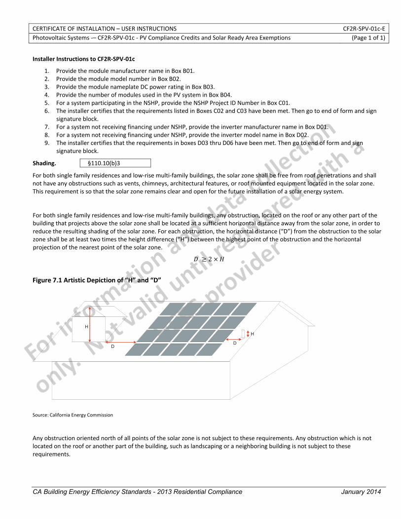
CERTIFICATE OF INSTALLATION – USER INSTRUCTIONS CF2R‐SPV‐01c‐E Photovoltaic Systems ‐– CF2R‐SPV‐01c ‐ PV Compliance Credits and Solar Ready Area Exemptions (Page 1 of 1)
CA Building Energy Efficiency Standards - 2013 Residential Compliance January 2014
Installer Instructions to CF2R‐SPV‐01c
1. Provide the module manufacturer name in Box B01. 2. Provide the module model number in Box B02. 3. Provide the module nameplate DC power rating in Box B03. 4. Provide the number of modules used in the PV system in Box B04. 5. For a system participating in the NSHP, provide the NSHP Project ID Number in Box C01. 6. The installer certifies that the requirements listed in Boxes C02 and C03 have been met. Then go to end of form and sign
signature block. 7. For a system not receiving financing under NSHP, provide the inverter manufacturer name in Box D01. 8. For a system not receiving financing under NSHP, provide the inverter model name in Box D02. 9. The installer certifies that the requirements in boxes D03 thru D06 have been met. Then go to end of form and sign
signature block.
Shading. §110.10(b)3
For both single family residences and low‐rise multi‐family buildings, the solar zone shall be free from roof penetrations and shall not have any obstructions such as vents, chimneys, architectural features, or roof mounted equipment located in the solar zone. This requirement is so that the solar zone remains clear and open for the future installation of a solar energy system.
For both single family residences and low‐rise multi‐family buildings, any obstruction, located on the roof or any other part of the building that projects above the solar zone shall be located at a sufficient horizontal distance away from the solar zone, in order to reduce the resulting shading of the solar zone. For each obstruction, the horizontal distance (“D”) from the obstruction to the solar zone shall be at least two times the height difference (“H”) between the highest point of the obstruction and the horizontal projection of the nearest point of the solar zone.
2
Figure 7.1 Artistic Depiction of “H” and “D”
Source: California Energy Commission
H
DD
H
Any obstruction oriented north of all points of the solar zone is not subject to these requirements. Any obstruction which is not located on the roof or another part of the building, such as landscaping or a neighboring building is not subject to these requirements.
CERTIFICATE OF INSTALLATION – DATA FIELD DEFINITIONS AND CALCULATIONS CF2R‐SPV‐01c‐E Photovoltaic Systems ‐– CF2R‐SPV‐01c ‐ PV Compliance Credits and Solar Ready Area Exemptions (Page 3 of 3)
CA Building Energy Efficiency Standards - 2013 Residential Compliance January 2014
DOCUMENTATION AUTHOR'S DECLARATION STATEMENT
1. I certify that this Certificate of Installation documentation is accurate and complete.
Documentation Author Name: Documentation Author Signature:
Documentation Author Company Name: Date Signed:
Address: CEA/CEPE/HERS certification identification (If applicable):
City/State/Zip: Phone:
RESPONSIBLE PERSON'S DECLARATION STATEMENT
I certify the following under penalty of perjury, under the laws of the State of California:
1. The information provided on this Certificate of Installation is true and correct.
2. I am eligible under Division 3 of the Business and Professions Code to accept responsibility for the scope of construction or installation, in the applicable classification, for the scope of work specified on this Certificate of Installation (responsible builder/installer), otherwise I am an authorized representative of the responsible builder/installer.
3. The constructed or installed features, materials, components or manufactured devices (the installation) identified on this Certificate of Installation conforms to all applicable codes and regulations, and the installation conforms to the requirements given on the plans and specifications approved by the enforcement agency.
4. I reviewed a copy of the Certificate of Compliance approved by the enforcement agency that identifies the specific requirements for the scope of construction or installation identified on this Certificate of Installation, and I have ensured that the requirements that apply to the construction or installation have been met.
5. I will ensure that a registered copy of this Certificate of Installation shall be posted, or made available with the building permit(s) issued for the building, and made available to the enforcement agency for all applicable inspections. I understand that a registered copy of this Certificate of Installation is required to be included with the documentation the builder provides to the building owner at occupancy.
Responsible Builder/Installer Name: Responsible Builder/Installer Signature:
Company Name: (Installing Subcontractor or General Contractor or Builder/Owner) Position With Company (Title):
Address: CSLB License:
City/State/Zip: Phone Date Signed:

STATE OF CALIFORNIA
SPACE CONDITIONING SYSTEMS DUCTS AND FANS CEC-CF2R-MCH-01-H (Revised 06/13) CALIFORNIA ENERGY COMMISSION
CERTIFICATE OF INSTALLATION CF2R‐MCH‐01‐H Space Conditioning Systems Ducts and Fans (Page 1 of 5) Project Name: Enforcement Agency: Permit Number:
Dwelling Address: City Zip Code
Registration Number: Registration Date/Time: HERS Provider:
A. General Information
01 Dwelling Unit Name 02Number of Space Conditioning Systems in this dwelling unit
03 Dwelling Unit Conditioned Floor Area (ft2)
04Number of Space Conditioning Zones in this dwelling unit
05 Certificate of Compliance Type 06 method used to calculate HVAC loads
07 Calculated Cooling Load (Btuh) 08 Calculated Heating Load (Btuh)
09 Determination of Mech01 type (this row not visible to user)
B. Space Conditioning (SC) System Requirements from CF1R
01 02 03 04 05 06 07 08 09 SC System
Identification or Name
Heating System Type
Heating Efficiency
Cooling System Type
Cooling Efficiency SEER
Cooling Efficiency EER
Duct System Name Cooling Zoning
Type
Minimum Cooling Zone Airflow Rate
(cfm/ton)
Notes: C. Installed Space Conditioning (SC) System Information
01 02 03 04 05 06 07 08 SC System
Identification or Name
SC System Location or Area Served
SC System Installation Type Cooling System Type
SC System Distribution Type
Cooling System Zoning Type
Conditioned Floor Area served by the
system (ft2) SC System
Thermostat type
Notes:
CA Building Energy Efficiency Standards ‐ 2013 Residential Compliance January 2014
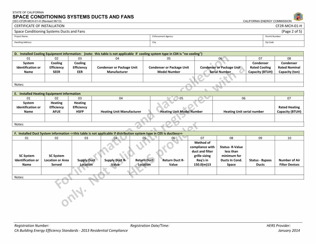
STATE OF CALIFORNIA
SPACE CONDITIONING SYSTEMS DUCTS AND FANS CEC-CF2R-MCH-01-H (Revised 06/13) CALIFORNIA ENERGY COMMISSION
CERTIFICATE OF INSTALLATION CF2R‐MCH‐01‐H Space Conditioning Systems Ducts and Fans (Page 2 of 5) Project Name: Enforcement Agency: Permit Number:
Dwelling Address: City Zip Code
Registration Number: Registration Date/Time: HERS Provider:
D. Installed Cooling Equipment information: (note: this table is not applicable if cooling system type in C04 is "no cooling") 01 02 03 04 05 06 07 08
System Identification or
Name
Cooling Efficiency SEER
Cooling Efficiency
EER Condenser or Package Unit
Manufacturer Condenser or Package Unit
Model Number Condenser or Package Unit
Serial Number
Condenser Rated Cooling Capacity (BTUH)
Condenser Rated Nominal Capacity (ton)
Notes: E. Installed Heating Equipment information
01 02 03 04 05 06 07 System
Identification or Name
Heating Efficiency AFUE
Heating Efficiency HSFP Heating Unit Manufacturer Heating Unit Model Number Heating Unit serial number
Rated Heating Capacity (BTUH)
Notes: F. Installed Duct System information <<this table is not applicable if distribution system type in C05 is ductless>>
01 02 03 04 05 06 07 08 09 10
SC System Identification or
Name
SC System Location or Area
Served Supply Duct Location
Supply Duct R‐Value
Return Duct Location
Return Duct R‐Value
Method of compliance with duct and filter grille sizing Req's in
150.0(m)13
Status‐ R‐Value less than
minimum for Ducts In Cond.
Space Status ‐ Bypass
Ducts Number of Air Filter Devices
Notes:
CA Building Energy Efficiency Standards ‐ 2013 Residential Compliance January 2014
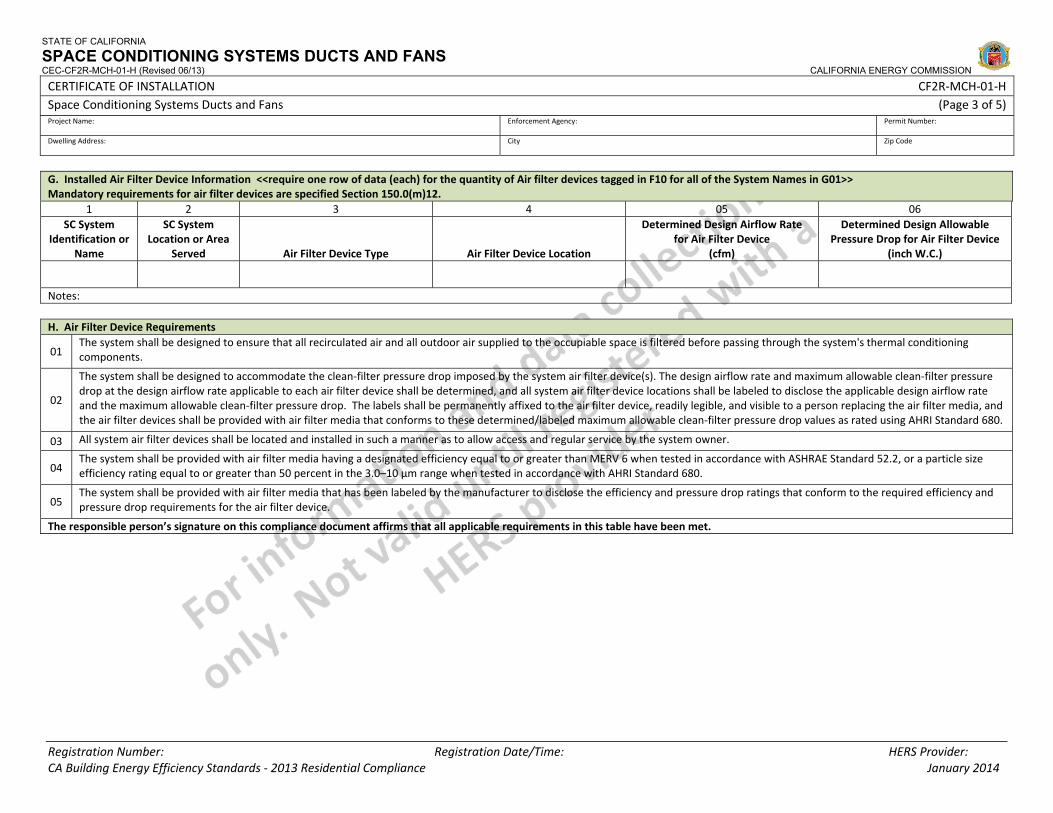
STATE OF CALIFORNIA
SPACE CONDITIONING SYSTEMS DUCTS AND FANS CEC-CF2R-MCH-01-H (Revised 06/13) CALIFORNIA ENERGY COMMISSION
CERTIFICATE OF INSTALLATION CF2R‐MCH‐01‐H Space Conditioning Systems Ducts and Fans (Page 3 of 5) Project Name: Enforcement Agency: Permit Number:
Dwelling Address: City Zip Code
Registration Number: Registration Date/Time: HERS Provider:
G. Installed Air Filter Device Information <<require one row of data (each) for the quantity of Air filter devices tagged in F10 for all of the System Names in G01>> Mandatory requirements for air filter devices are specified Section 150.0(m)12.
1 2 3 4 05 06 SC System
Identification or Name
SC System Location or Area
Served Air Filter Device Type Air Filter Device Location
Determined Design Airflow Rate for Air Filter Device
(cfm)
Determined Design Allowable Pressure Drop for Air Filter Device
(inch W.C.)
Notes: H. Air Filter Device Requirements
01 The system shall be designed to ensure that all recirculated air and all outdoor air supplied to the occupiable space is filtered before passing through the system's thermal conditioning components.
02
The system shall be designed to accommodate the clean‐filter pressure drop imposed by the system air filter device(s). The design airflow rate and maximum allowable clean‐filter pressure drop at the design airflow rate applicable to each air filter device shall be determined, and all system air filter device locations shall be labeled to disclose the applicable design airflow rate and the maximum allowable clean‐filter pressure drop. The labels shall be permanently affixed to the air filter device, readily legible, and visible to a person replacing the air filter media, and the air filter devices shall be provided with air filter media that conforms to these determined/labeled maximum allowable clean‐filter pressure drop values as rated using AHRI Standard 680.
03 All system air filter devices shall be located and installed in such a manner as to allow access and regular service by the system owner.
04 The system shall be provided with air filter media having a designated efficiency equal to or greater than MERV 6 when tested in accordance with ASHRAE Standard 52.2, or a particle size efficiency rating equal to or greater than 50 percent in the 3.0–10 μm range when tested in accordance with AHRI Standard 680.
05 The system shall be provided with air filter media that has been labeled by the manufacturer to disclose the efficiency and pressure drop ratings that conform to the required efficiency and pressure drop requirements for the air filter device.
The responsible person’s signature on this compliance document affirms that all applicable requirements in this table have been met.
CA Building Energy Efficiency Standards ‐ 2013 Residential Compliance January 2014
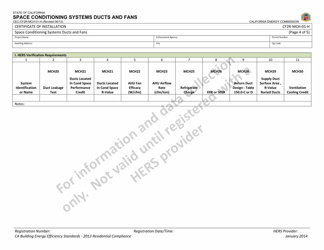
STATE OF CALIFORNIA
SPACE CONDITIONING SYSTEMS DUCTS AND FANS CEC-CF2R-MCH-01-H (Revised 06/13) CALIFORNIA ENERGY COMMISSION
CERTIFICATE OF INSTALLATION CF2R‐MCH‐01‐H Space Conditioning Systems Ducts and Fans (Page 4 of 5) Project Name: Enforcement Agency: Permit Number:
Dwelling Address: City Zip Code
Registration Number: Registration Date/Time: HERS Provider:
I. HERS Verification Requirements 1 2 3 4 5 6 7 8 9 10 11
MCH20 MCH21 MCH21 MCH22 MCH23 MCH25 MCH26 MCH28 MCH29 MCH30
System Identification or Name
Duct Leakage Test
Ducts Located In Cond Space Performance
Credit
Ducts Located In Cond Space
R‐Value
AHU Fan Efficacy (W/cfm)
AHU Airflow Rate
(cfm/ton) Refrigerant Charge EER or SEER
Return Duct Design ‐ Table 150.0‐C or D
Supply Duct Surface Area ,
R‐Value Buried Ducts
Ventilation Cooling Credit
Notes:
CA Building Energy Efficiency Standards ‐ 2013 Residential Compliance January 2014
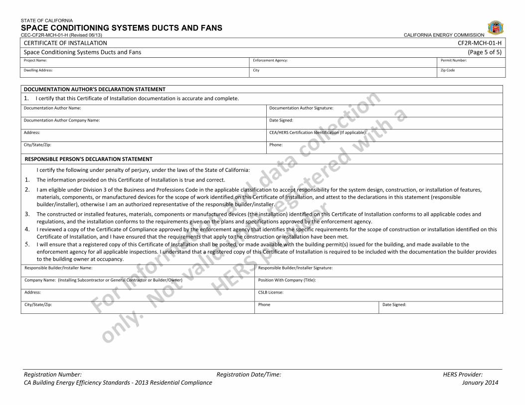
STATE OF CALIFORNIA
SPACE CONDITIONING SYSTEMS DUCTS AND FANS CEC-CF2R-MCH-01-H (Revised 06/13) CALIFORNIA ENERGY COMMISSION
CERTIFICATE OF INSTALLATION CF2R‐MCH‐01‐H Space Conditioning Systems Ducts and Fans (Page 5 of 5) Project Name: Enforcement Agency: Permit Number:
Dwelling Address: City Zip Code
Registration Number: Registration Date/Time: HERS Provider: CA Building Energy Efficiency Standards ‐ 2013 Residential Compliance January 2014
DOCUMENTATION AUTHOR'S DECLARATION STATEMENT
1. I certify that this Certificate of Installation documentation is accurate and complete.
Documentation Author Name: Documentation Author Signature:
Documentation Author Company Name: Date Signed:
Address: CEA/HERS Certification Identification (If applicable):
City/State/Zip: Phone:
RESPONSIBLE PERSON'S DECLARATION STATEMENT
I certify the following under penalty of perjury, under the laws of the State of California:
1. The information provided on this Certificate of Installation is true and correct.
2. I am eligible under Division 3 of the Business and Professions Code in the applicable classification to accept responsibility for the system design, construction, or installation of features, materials, components, or manufactured devices for the scope of work identified on this Certificate of Installation, and attest to the declarations in this statement (responsible builder/installer), otherwise I am an authorized representative of the responsible builder/installer.
3. The constructed or installed features, materials, components or manufactured devices (the installation) identified on this Certificate of Installation conforms to all applicable codes and regulations, and the installation conforms to the requirements given on the plans and specifications approved by the enforcement agency.
4. I reviewed a copy of the Certificate of Compliance approved by the enforcement agency that identifies the specific requirements for the scope of construction or installation identified on this Certificate of Installation, and I have ensured that the requirements that apply to the construction or installation have been met.
5. I will ensure that a registered copy of this Certificate of Installation shall be posted, or made available with the building permit(s) issued for the building, and made available to the enforcement agency for all applicable inspections. I understand that a registered copy of this Certificate of Installation is required to be included with the documentation the builder provides to the building owner at occupancy.
Responsible Builder/Installer Name: Responsible Builder/Installer Signature:
Company Name: (Installing Subcontractor or General Contractor or Builder/Owner) Position With Company (Title):
Address: CSLB License:
City/State/Zip: Phone Date Signed:
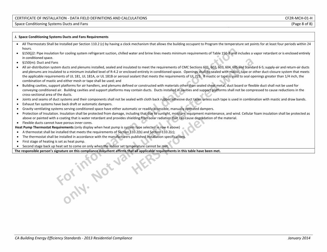
CERTIFICATE OF INSTALLATION ‐ DATA FIELD DEFINITIONS AND CALCULATIONS CF2R‐MCH‐01‐H Space Conditioning Systems Ducts and Fans (Page 8 of 8)
CA Building Energy Efficiency Standards ‐ 2013 Residential Compliance January 2014
J. Space Conditioning Systems Ducts and Fans Requirements
• All Thermostats Shall be Installed per Section 110.2 (c) by having a clock mechanism that allows the building occupant to Program the temperature set points for at least four periods within 24 hours.
• §150(j)2: Pipe insulation for cooling system refrigerant suction, chilled water and brine lines meets minimum requirements of Table 150‐B and includes a vapor retardant or is enclosed entirely in conditioned space.
• §150(m): Duct and Fans • All air‐distribution system ducts and plenums installed, sealed and insulated to meet the requirements of CMC Sections 601, 602, 603, 604, 605 and Standard 6‐5; supply‐air and return‐air ducts
and plenums are insulated to a minimum installed level of R‐4.2 or enclosed entirely in conditioned space. Openings shall be sealed with mastic, tape or other duct‐closure system that meets the applicable requirements of UL 181, UL 181A, or UL 181B or aerosol sealant that meets the requirements of UL 723. If mastic or tape is used to seal openings greater than 1/4 inch, the combination of mastic and either mesh or tape shall be used; and
• Building cavities, support platforms for air handlers, and plenums defined or constructed with materials other than sealed sheet metal, duct board or flexible duct shall not be used for conveying conditioned air. Building cavities and support platforms may contain ducts. Ducts installed in cavities and support platforms shall not be compressed to cause reductions in the cross‐sectional area of the ducts.
• Joints and seams of duct systems and their components shall not be sealed with cloth back rubber adhesive duct tapes unless such tape is used in combination with mastic and draw bands. • Exhaust fan systems have back draft or automatic dampers. • Gravity ventilating systems serving conditioned space have either automatic or readily accessible, manually operated dampers. • Protection of Insulation. Insulation shall be protected from damage, including that due to sunlight, moisture, equipment maintenance, and wind. Cellular foam insulation shall be protected as
above or painted with a coating that is water retardant and provides shielding from solar radiation that can cause degradation of the material. • Flexible ducts cannot have porous inner cores. Heat Pump Thermostat Requirements (only display when heat pump is system type selected in row 4 above) • A thermostat shall be installed that meets the requirements of Section 110.2(b) and Section 110.2(c); • The thermostat shall be installed in accordance with the manufacturers published installation specifications. • First stage of heating is set as heat pump. • Second stage back up heat set to come on only when the indoor set temperature cannot be met.
The responsible person’s signature on this compliance document affirms that all applicable requirements in this table have been met.
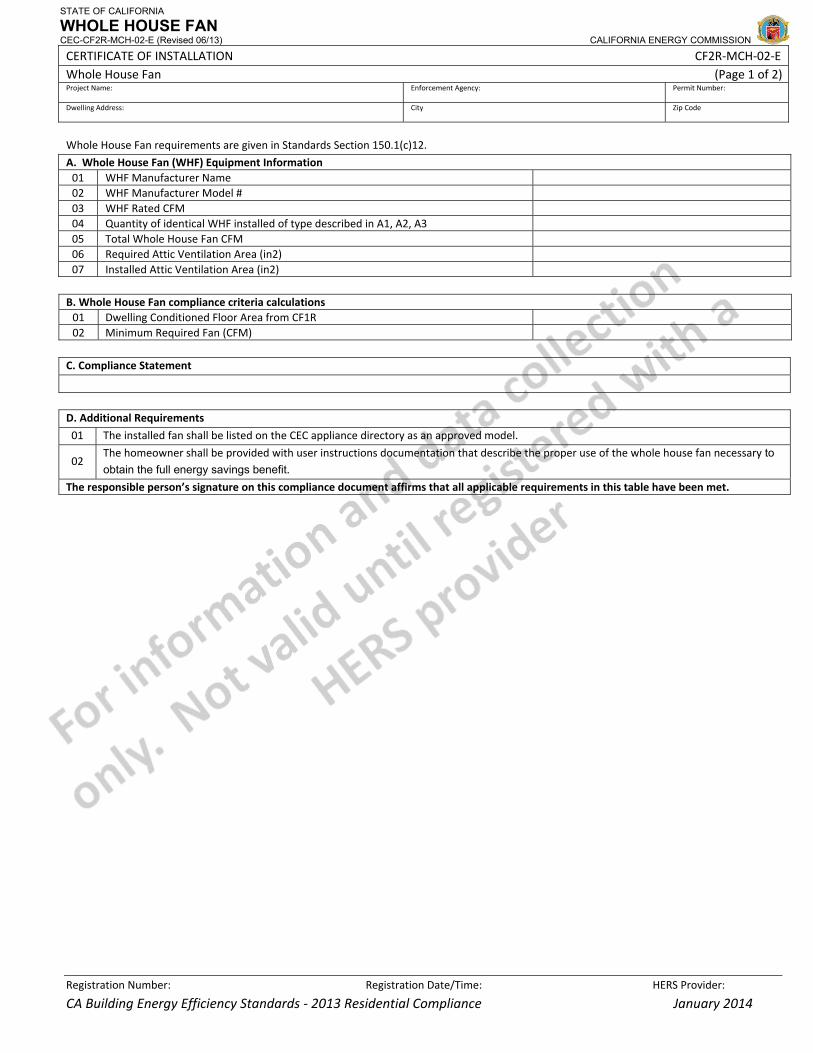
STATE OF CALIFORNIA
WHOLE HOUSE FAN CEC-CF2R-MCH-02-E (Revised 06/13) CALIFORNIA ENERGY COMMISSION
CERTIFICATE OF INSTALLATION CF2R‐MCH‐02‐E Whole House Fan (Page 1 of 2)Project Name: Enforcement Agency: Permit Number:
Dwelling Address: City Zip Code
Registration Number: Registration Date/Time: HERS Provider:
CA Building Energy Efficiency Standards ‐ 2013 Residential Compliance January 2014
Whole House Fan requirements are given in Standards Section 150.1(c)12.
A. Whole House Fan (WHF) Equipment Information 01 WHF Manufacturer Name 02 WHF Manufacturer Model # 03 WHF Rated CFM 04 Quantity of identical WHF installed of type described in A1, A2, A3 05 Total Whole House Fan CFM 06 Required Attic Ventilation Area (in2) 07 Installed Attic Ventilation Area (in2)
B. Whole House Fan compliance criteria calculations 01 Dwelling Conditioned Floor Area from CF1R 02 Minimum Required Fan (CFM)
C. Compliance Statement
D. Additional Requirements
01 The installed fan shall be listed on the CEC appliance directory as an approved model.
02 The homeowner shall be provided with user instructions documentation that describe the proper use of the whole house fan necessary to obtain the full energy savings benefit.
The responsible person’s signature on this compliance document affirms that all applicable requirements in this table have been met.

STATE OF CALIFORNIA
WHOLE HOUSE FAN CEC-CF2R-MCH-02-E (Revised 06/13) CALIFORNIA ENERGY COMMISSION
CERTIFICATE OF INSTALLATION CF2R‐MCH‐02‐E Whole House Fan (Page 2 of 2)Project Name: Enforcement Agency: Permit Number:
Dwelling Address: City Zip Code
Registration Number: Registration Date/Time: HERS Provider:
CA Building Energy Efficiency Standards ‐ 2013 Residential Compliance January 2014
DOCUMENTATION AUTHOR'S DECLARATION STATEMENT
1. I certify that this Certificate of Installation documentation is accurate and complete.
Documentation Author Name: Documentation Author Signature:
Documentation Author Company Name: Date Signed:
Address: CEA/HERS Certification Identification (If applicable):
City/State/Zip: Phone:
RESPONSIBLE PERSON'S DECLARATION STATEMENT
I certify the following under penalty of perjury, under the laws of the State of California:
1. The information provided on this Certificate of Installation is true and correct.
2. I am eligible under Division 3 of the Business and Professions Code in the applicable classification to accept responsibility for the system design, construction, or installation of features, materials, components, or manufactured devices for the scope of work identified on this Certificate of Installation, and attest to the declarations in this statement (responsible builder/installer), otherwise I am an authorized representative of the responsible builder/installer.
3. The constructed or installed features, materials, components or manufactured devices (the installation) identified on this Certificate of Installation conforms to all applicable codes and regulations, and the installation conforms to the requirements given on the plans and specifications approved by the enforcement agency.
4. I reviewed a copy of the Certificate of Compliance approved by the enforcement agency that identifies the specific requirements for the scope of construction or installation identified on this Certificate of Installation, and I have ensured that the requirements that apply to the construction or installation have been met.
5. I will ensure that a registered copy of this Certificate of Installation shall be posted, or made available with the building permit(s) issued for the building, and made available to the enforcement agency for all applicable inspections. I understand that a registered copy of this Certificate of Installation is required to be included with the documentation the builder provides to the building owner at occupancy.
Responsible Builder/Installer Name: Responsible Builder/Installer Signature:
Company Name: (Installing Subcontractor or General Contractor or Builder/Owner) Position With Company (Title):
Address: CSLB License:
City/State/Zip: Phone Date Signed:
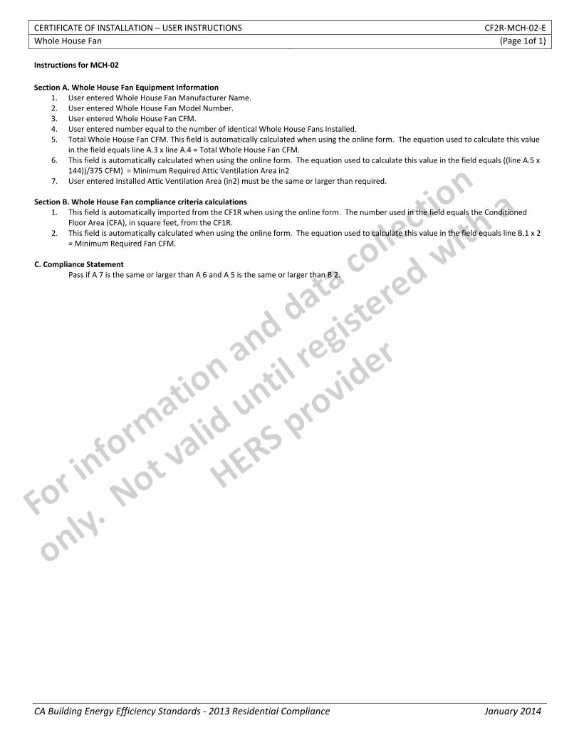
CERTIFICATE OF INSTALLATION – USER INSTRUCTIONS CF2R‐MCH‐02‐E Whole House Fan (Page 1of 1)
CA Building Energy Efficiency Standards ‐ 2013 Residential Compliance January 2014
Instructions for MCH‐02 Section A. Whole House Fan Equipment Information
1. User entered Whole House Fan Manufacturer Name. 2. User entered Whole House Fan Model Number. 3. User entered Whole House Fan CFM. 4. User entered number equal to the number of identical Whole House Fans Installed. 5. Total Whole House Fan CFM. This field is automatically calculated when using the online form. The equation used to calculate this value
in the field equals line A.3 x line A.4 = Total Whole House Fan CFM. 6. This field is automatically calculated when using the online form. The equation used to calculate this value in the field equals ((line A.5 x
144))/375 CFM) = Minimum Required Attic Ventilation Area in2 7. User entered Installed Attic Ventilation Area (in2) must be the same or larger than required.
Section B. Whole House Fan compliance criteria calculations
1. This field is automatically imported from the CF1R when using the online form. The number used in the field equals the Conditioned Floor Area (CFA), in square feet, from the CF1R.
2. This field is automatically calculated when using the online form. The equation used to calculate this value in the field equals line B.1 x 2 = Minimum Required Fan CFM.
C. Compliance Statement
Pass if A 7 is the same or larger than A 6 and A 5 is the same or larger than B 2.
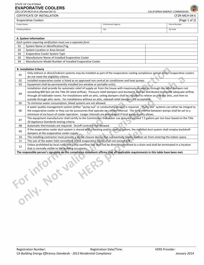
STATE OF CALIFORNIA
EVAPORATIVE COOLERS CEC-CF2R-MCH-04-E (Revised 06/13) CALIFORNIA ENERGY COMMISSION
CERTIFICATE OF INSTALLATION CF2R‐MCH‐04‐E Evaporative Coolers (Page 1 of 2) Project Name: Enforcement Agency: Permit Number:
Dwelling Address: City Zip Code
Registration Number: Registration Date/Time: HERS Provider: CA Building Energy Efficiency Standards ‐ 2013 Residential Compliance January 2014
A. System Information Each system requiring verification must use a separate form 01 System Name or Identification/Tag 02 System Location or Area Served 03 Evaporative Cooler System Type 03 Manufacturer Name of Installed Evaporative Cooler 04 Manufacturer Model Number of Installed Evaporative Cooler B. Installation Criteria
01 Only indirect or direct/indirect systems may be installed as part of the evaporative cooling compliance option. Direct evaporative coolers do not meet the eligibility criteria.
02 Installed evaporative cooler is listed as an approved non central air conditioner and heat pumps. 03 Equipment shall be permanently installed (no window or portable units).
04
Installation shall provide for automatic relief of supply air from the house with maximum air velocity through the relief dampers not exceeding 800 fpm (at the Title 20 rated airflow). Pressure relief dampers and ductwork shall be distributed to provide adequate airflow through all habitable rooms. For installations with an attic, ceiling dampers shall be installed to relieve air into the attic, and then to outside through attic vents. For installations without an attic, sidewall relief dampers are acceptable.
05 To minimize water consumption, bleed systems are not allowed.
06 A water quality management system (either “pump out” or conductivity sensor) is required. “Pump out” systems can either be integral to the evaporative cooler or they can be accessories that operate on a timed interval. The time interval between dumps shall be set to a minimum of six hours of cooler operation. Longer intervals are encouraged if local water quality allows.
07 The equipment manufacturer shall certify to the Commission that water use does not exceed 7.5 gallons per ton hour based on the Title 20 Appliance Standards testing criteria.
08 Automatic thermostats are required. On/off control is not allowed.
09 If the evaporative cooler duct system is shared with a heating and/or cooling system, the installed duct system shall employ backdraft dampers at the evaporative cooler supply.
10 The installing contractor must provide a winter closure device that substantially blocks outdoor air from entering the indoor space. 11 The size of the water inlet connection at the evaporative cooler shall not exceed 3/8”.
12 Unless prohibited by local code, the sump overflow line shall not be directly connected to a drain and shall be terminated in a location that is normally visible to the building occupants.
The responsible person’s signature on this compliance document affirms that all applicable requirements in this table have been met.
STATE OF CALIFORNIA
EVAPORATIVE COOLERS CEC-CF2R-MCH-04-E (Revised 06/13) CALIFORNIA ENERGY COMMISSION
CERTIFICATE OF INSTALLATION CF2R‐MCH‐04‐E Evaporative Coolers (Page 2 of 2) Project Name: Enforcement Agency: Permit Number:
Dwelling Address: City Zip Code
Registration Number: Registration Date/Time: HERS Provider: CA Building Energy Efficiency Standards ‐ 2013 Residential Compliance January 2014
DOCUMENTATION AUTHOR'S DECLARATION STATEMENT
1. I certify that this Certificate of Installation documentation is accurate and complete.
Documentation Author Name: Documentation Author Signature:
Documentation Author Company Name: Date Signed:
Address: CEA/HERS Certification Identification (If applicable):
City/State/Zip: Phone:
RESPONSIBLE PERSON'S DECLARATION STATEMENT
I certify the following under penalty of perjury, under the laws of the State of California:
1. The information provided on this Certificate of Installation is true and correct.
2. I am eligible under Division 3 of the Business and Professions Code in the applicable classification to accept responsibility for the system design, construction, or installation of features, materials, components, or manufactured devices for the scope of work identified on this Certificate of Installation, and attest to the declarations in this statement (responsible builder/installer), otherwise I am an authorized representative of the responsible builder/installer.
3. The constructed or installed features, materials, components or manufactured devices (the installation) identified on this Certificate of Installation conforms to all applicable codes and regulations, and the installation conforms to the requirements given on the plans and specifications approved by the enforcement agency.
4. I reviewed a copy of the Certificate of Compliance approved by the enforcement agency that identifies the specific requirements for the scope of construction or installation identified on this Certificate of Installation, and I have ensured that the requirements that apply to the construction or installation have been met.
5. I will ensure that a registered copy of this Certificate of Installation shall be posted, or made available with the building permit(s) issued for the building, and made available to the enforcement agency for all applicable inspections. I understand that a registered copy of this Certificate of Installation is required to be included with the documentation the builder provides to the building owner at occupancy.
Responsible Builder/Installer Name: Responsible Builder/Installer Signature:
Company Name: (Installing Subcontractor or General Contractor or Builder/Owner) Position With Company (Title):
Address: CSLB License:
City/State/Zip: Phone Date Signed:
CERTIFICATE OF INSTALLATION – USER INSTRUCTIONS CF2R‐MCH‐04‐E Evaporative Coolers (Page 1 of 1)
CA Building Energy Efficiency Standards - 2013 Residential Compliance January 2014
Instructions for MCH‐04 Section A. Evaporative Cooler Equipment Information 1. This field is automatically imported from the MCH‐01‐CF‐2R when using the online form. The number entered in the field equals
evaporative cooler system name or identification/tag from the building plans. 2. This field is automatically imported from the MCH‐01‐CF‐2R when using the online form. The number entered in the field equals
evaporative cooler system location or the area served. 3. This field is automatically imported from the MCH‐01‐CF‐2R when using the online form. The number entered in the field equals indirect
or direct/indirect. 4. User entered Evaporative Cooler Manufacturer Name. 5. User entered Evaporative Cooler Model Number.
CERTIFICATE OF INSTALLATION – DATA FIELD DEFINITION AND CALCULATIONS CF2R‐MCH‐04‐E Evaporative Coolers (Page 2 of 2)
CA Building Energy Efficiency Standards - 2013 Residential Compliance January 2014
DOCUMENTATION AUTHOR'S DECLARATION STATEMENT
1. I certify that this Certificate of Installation documentation is accurate and complete.
Documentation Author Name: Documentation Author Signature:
Documentation Author Company Name: Date Signed:
Address: CEA/HERS Certification Identification (If applicable):
City/State/Zip: Phone:
RESPONSIBLE PERSON'S DECLARATION STATEMENT
I certify the following under penalty of perjury, under the laws of the State of California:
1. The information provided on this Certificate of Installation is true and correct.
2. I am eligible under Division 3 of the Business and Professions Code in the applicable classification to accept responsibility for the system design, construction, or installation of features, materials, components, or manufactured devices for the scope of work identified on this Certificate of Installation, and attest to the declarations in this statement (responsible builder/installer), otherwise I am an authorized representative of the responsible builder/installer.
3. The constructed or installed features, materials, components or manufactured devices (the installation) identified on this Certificate of Installation conforms to all applicable codes and regulations, and the installation conforms to the requirements given on the plans and specifications approved by the enforcement agency.
4. I reviewed a copy of the Certificate of Compliance approved by the enforcement agency that identifies the specific requirements for the scope of construction or installation identified on this Certificate of Installation, and I have ensured that the requirements that apply to the construction or installation have been met.
5. I will ensure that a registered copy of this Certificate of Installation shall be posted, or made available with the building permit(s) issued for the building, and made available to the enforcement agency for all applicable inspections. I understand that a registered copy of this Certificate of Installation is required to be included with the documentation the builder provides to the building owner at occupancy.
Responsible Builder/Installer Name: Responsible Builder/Installer Signature:
Company Name: (Installing Subcontractor or General Contractor or Builder/Owner) Position With Company (Title):
Address: CSLB License:
City/State/Zip: Phone Date Signed:
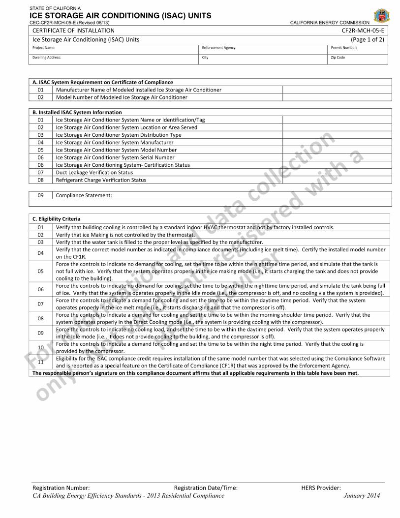
STATE OF CALIFORNIA
ICE STORAGE AIR CONDITIONING (ISAC) UNITS CEC-CF2R-MCH-05-E (Revised 06/13) CALIFORNIA ENERGY COMMISSION
CERTIFICATE OF INSTALLATION CF2R‐MCH‐05‐E Ice Storage Air Conditioning (ISAC) Units (Page 1 of 2) Project Name: Enforcement Agency: Permit Number:
Dwelling Address: City Zip Code
Registration Number: Registration Date/Time: HERS Provider: CA Building Energy Efficiency Standards - 2013 Residential Compliance January 2014
A. ISAC System Requirement on Certificate of Compliance 01 Manufacturer Name of Modeled Installed Ice Storage Air Conditioner 02 Model Number of Modeled Ice Storage Air Conditioner
B. Installed ISAC System Information 01 Ice Storage Air Conditioner System Name or Identification/Tag 02 Ice Storage Air Conditioner System Location or Area Served 03 Ice Storage Air Conditioner System Distribution Type 04 Ice Storage Air Conditioner System Manufacturer 05 Ice Storage Air Conditioner System Model Number 06 Ice Storage Air Conditioner System Serial Number 06 Ice Storage Air Conditioning System‐ Certification Status 07 Duct Leakage Verification Status 08 Refrigerant Charge Verification Status
09 Compliance Statement:
C. Eligibility Criteria
01 Verify that building cooling is controlled by a standard indoor HVAC thermostat and not by factory installed controls. 02 Verify that ice Making is not controlled by the thermostat. 03 Verify that the water tank is filled to the proper level as specified by the manufacturer.
04 Verify that the correct model number as indicated in compliance documents (including ice melt time). Certify the installed model number on the CF1R.
05 Force the controls to indicate no demand for cooling, set the time to be within the nighttime time period, and simulate that the tank is not full with ice. Verify that the system operates properly in the ice making mode (i.e., it starts charging the tank and does not provide cooling to the building).
06 Force the controls to indicate no demand for cooling, set the time to be within the nighttime time period, and simulate the tank being full of ice. Verify that the system is operates properly in the Idle mode (i.e., the compressor is off, and no cooling via the system is provided).
07 Force the controls to indicate a demand for cooling and set the time to be within the daytime time period. Verify that the system operates properly in the ice melt mode (i.e., it starts discharging and that the compressor is off).
08 Force the controls to indicate a demand for cooling and set the time to be within the morning shoulder time period. Verify that the system operates properly in the Direct Cooling mode (i.e., the system is providing cooling with the compressor).
09 Force the controls to indicate no cooling load, and set the time to be within the daytime period. Verify that the system operates properly in the Idle mode (i.e., it does not provide cooling to the building, and the compressor is off).
10 Force the controls to indicate a demand for cooling and set the time to be within the night time period. Verify that the cooling is provided by the compressor.
11 Eligibility for the ISAC compliance credit requires installation of the same model number that was selected using the Compliance Software and is reported as a special feature on the Certificate of Compliance (CF1R) that was approved by the Enforcement Agency.
The responsible person’s signature on this compliance document affirms that all applicable requirements in this table have been met.
STATE OF CALIFORNIA
ICE STORAGE AIR CONDITIONING (ISAC) UNITS CEC-CF2R-MCH-05-E (Revised 06/13) CALIFORNIA ENERGY COMMISSION
CERTIFICATE OF INSTALLATION CF2R‐MCH‐05‐E Ice Storage Air Conditioning (ISAC) Units (Page 2 of 2) Project Name: Enforcement Agency: Permit Number:
Dwelling Address: City Zip Code
Registration Number: Registration Date/Time: HERS Provider: CA Building Energy Efficiency Standards - 2013 Residential Compliance January 2014
DOCUMENTATION AUTHOR'S DECLARATION STATEMENT
1. I certify that this Certificate of Installation documentation is accurate and complete.
Documentation Author Name: Documentation Author Signature:
Documentation Author Company Name: Date Signed:
Address: CEA/HERS Certification Identification (If applicable):
City/State/Zip: Phone:
RESPONSIBLE PERSON'S DECLARATION STATEMENT
I certify the following under penalty of perjury, under the laws of the State of California:
1. The information provided on this Certificate of Installation is true and correct.
2. I am eligible under Division 3 of the Business and Professions Code in the applicable classification to accept responsibility for the system design, construction, or installation of features, materials, components, or manufactured devices for the scope of work identified on this Certificate of Installation, and attest to the declarations in this statement (responsible builder/installer), otherwise I am an authorized representative of the responsible builder/installer.
3. The constructed or installed features, materials, components or manufactured devices (the installation) identified on this Certificate of Installation conforms to all applicable codes and regulations, and the installation conforms to the requirements given on the plans and specifications approved by the enforcement agency.
4. I reviewed a copy of the Certificate of Compliance approved by the enforcement agency that identifies the specific requirements for the scope of construction or installation identified on this Certificate of Installation, and I have ensured that the requirements that apply to the construction or installation have been met.
5. I will ensure that a registered copy of this Certificate of Installation shall be posted, or made available with the building permit(s) issued for the building, and made available to the enforcement agency for all applicable inspections. I understand that a registered copy of this Certificate of Installation is required to be included with the documentation the builder provides to the building owner at occupancy.
Responsible Builder/Installer Name: Responsible Builder/Installer Signature:
Company Name: (Installing Subcontractor or General Contractor or Builder/Owner) Position With Company (Title):
Address: CSLB License:
City/State/Zip: Phone Date Signed:
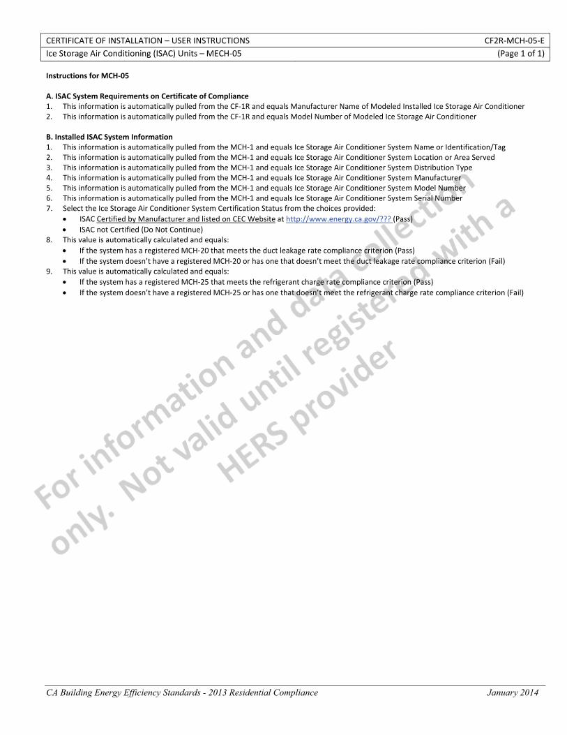
CERTIFICATE OF INSTALLATION – USER INSTRUCTIONS CF2R‐MCH‐05‐E Ice Storage Air Conditioning (ISAC) Units – MECH‐05 (Page 1 of 1)
CA Building Energy Efficiency Standards - 2013 Residential Compliance January 2014
Instructions for MCH‐05 A. ISAC System Requirements on Certificate of Compliance 1. This information is automatically pulled from the CF‐1R and equals Manufacturer Name of Modeled Installed Ice Storage Air Conditioner 2. This information is automatically pulled from the CF‐1R and equals Model Number of Modeled Ice Storage Air Conditioner B. Installed ISAC System Information 1. This information is automatically pulled from the MCH‐1 and equals Ice Storage Air Conditioner System Name or Identification/Tag 2. This information is automatically pulled from the MCH‐1 and equals Ice Storage Air Conditioner System Location or Area Served 3. This information is automatically pulled from the MCH‐1 and equals Ice Storage Air Conditioner System Distribution Type 4. This information is automatically pulled from the MCH‐1 and equals Ice Storage Air Conditioner System Manufacturer 5. This information is automatically pulled from the MCH‐1 and equals Ice Storage Air Conditioner System Model Number 6. This information is automatically pulled from the MCH‐1 and equals Ice Storage Air Conditioner System Serial Number 7. Select the Ice Storage Air Conditioner System Certification Status from the choices provided:
• ISAC Certified by Manufacturer and listed on CEC Website at http://www.energy.ca.gov/??? (Pass) • ISAC not Certified (Do Not Continue)
8. This value is automatically calculated and equals: • If the system has a registered MCH‐20 that meets the duct leakage rate compliance criterion (Pass) • If the system doesn’t have a registered MCH‐20 or has one that doesn’t meet the duct leakage rate compliance criterion (Fail)
9. This value is automatically calculated and equals: • If the system has a registered MCH‐25 that meets the refrigerant charge rate compliance criterion (Pass) • If the system doesn’t have a registered MCH‐25 or has one that doesn’t meet the refrigerant charge rate compliance criterion (Fail)
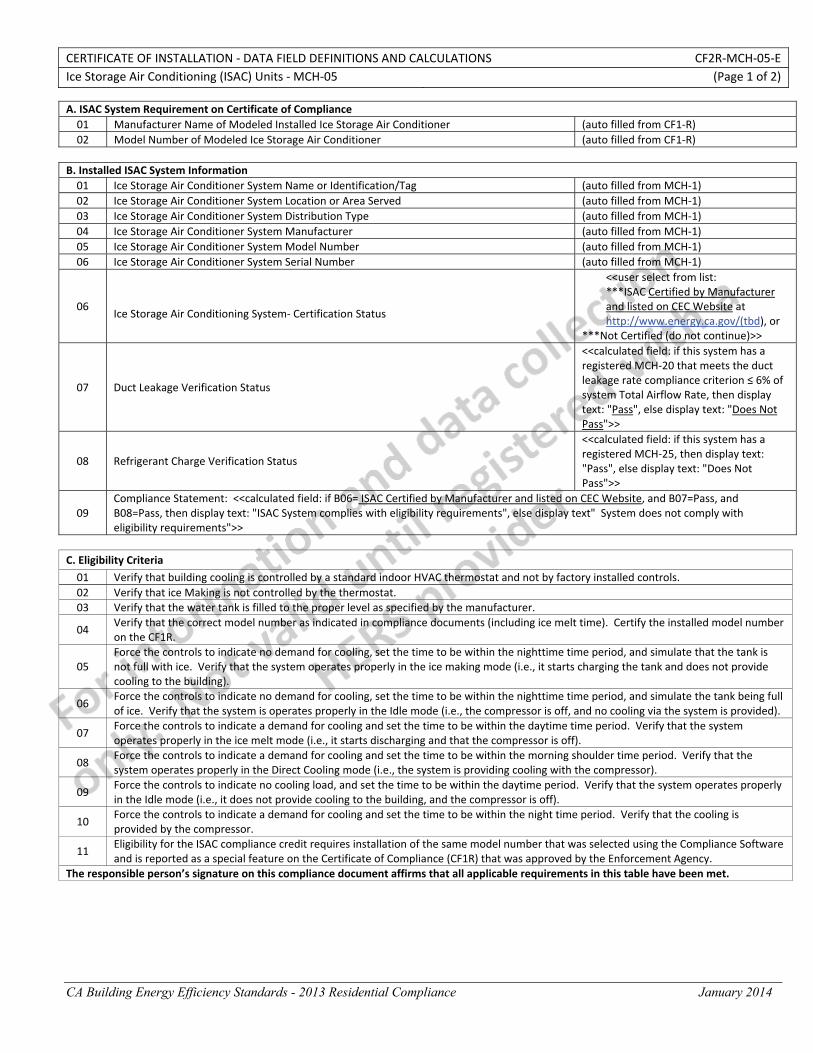
CERTIFICATE OF INSTALLATION ‐ DATA FIELD DEFINITIONS AND CALCULATIONS CF2R‐MCH‐05‐E Ice Storage Air Conditioning (ISAC) Units ‐ MCH‐05 (Page 1 of 2)
CA Building Energy Efficiency Standards - 2013 Residential Compliance January 2014
A. ISAC System Requirement on Certificate of Compliance 01 Manufacturer Name of Modeled Installed Ice Storage Air Conditioner (auto filled from CF1‐R) 02 Model Number of Modeled Ice Storage Air Conditioner (auto filled from CF1‐R)
B. Installed ISAC System Information 01 Ice Storage Air Conditioner System Name or Identification/Tag (auto filled from MCH‐1) 02 Ice Storage Air Conditioner System Location or Area Served (auto filled from MCH‐1) 03 Ice Storage Air Conditioner System Distribution Type (auto filled from MCH‐1) 04 Ice Storage Air Conditioner System Manufacturer (auto filled from MCH‐1) 05 Ice Storage Air Conditioner System Model Number (auto filled from MCH‐1) 06 Ice Storage Air Conditioner System Serial Number (auto filled from MCH‐1)
06 Ice Storage Air Conditioning System‐ Certification Status
<<user select from list: ***ISAC Certified by Manufacturer and listed on CEC Website at http://www.energy.ca.gov/(tbd), or
***Not Certified (do not continue)>>
07 Duct Leakage Verification Status
<<calculated field: if this system has a registered MCH‐20 that meets the duct leakage rate compliance criterion ≤ 6% of system Total Airflow Rate, then display text: "Pass", else display text: "Does Not Pass">>
08 Refrigerant Charge Verification Status
<<calculated field: if this system has a registered MCH‐25, then display text: "Pass", else display text: "Does Not Pass">>
09 Compliance Statement: <<calculated field: if B06= ISAC Certified by Manufacturer and listed on CEC Website, and B07=Pass, and B08=Pass, then display text: "ISAC System complies with eligibility requirements", else display text" System does not comply with eligibility requirements">>
C. Eligibility Criteria
01 Verify that building cooling is controlled by a standard indoor HVAC thermostat and not by factory installed controls. 02 Verify that ice Making is not controlled by the thermostat. 03 Verify that the water tank is filled to the proper level as specified by the manufacturer.
04 Verify that the correct model number as indicated in compliance documents (including ice melt time). Certify the installed model number on the CF1R.
05 Force the controls to indicate no demand for cooling, set the time to be within the nighttime time period, and simulate that the tank is not full with ice. Verify that the system operates properly in the ice making mode (i.e., it starts charging the tank and does not provide cooling to the building).
06 Force the controls to indicate no demand for cooling, set the time to be within the nighttime time period, and simulate the tank being full of ice. Verify that the system is operates properly in the Idle mode (i.e., the compressor is off, and no cooling via the system is provided).
07 Force the controls to indicate a demand for cooling and set the time to be within the daytime time period. Verify that the system operates properly in the ice melt mode (i.e., it starts discharging and that the compressor is off).
08 Force the controls to indicate a demand for cooling and set the time to be within the morning shoulder time period. Verify that the system operates properly in the Direct Cooling mode (i.e., the system is providing cooling with the compressor).
09 Force the controls to indicate no cooling load, and set the time to be within the daytime period. Verify that the system operates properly in the Idle mode (i.e., it does not provide cooling to the building, and the compressor is off).
10 Force the controls to indicate a demand for cooling and set the time to be within the night time period. Verify that the cooling is provided by the compressor.
11 Eligibility for the ISAC compliance credit requires installation of the same model number that was selected using the Compliance Software and is reported as a special feature on the Certificate of Compliance (CF1R) that was approved by the Enforcement Agency.
The responsible person’s signature on this compliance document affirms that all applicable requirements in this table have been met.
CERTIFICATE OF INSTALLATION ‐ DATA FIELD DEFINITIONS AND CALCULATIONS CF2R‐MCH‐05‐E Ice Storage Air Conditioning (ISAC) Units ‐ MCH‐05 (Page 2 of 2)
CA Building Energy Efficiency Standards - 2013 Residential Compliance January 2014
DOCUMENTATION AUTHOR'S DECLARATION STATEMENT
1. I certify that this Certificate of Installation documentation is accurate and complete.
Documentation Author Name: Documentation Author Signature:
Documentation Author Company Name: Date Signed:
Address: CEA/CEPE/HERS certification identification (If applicable):
City/State/Zip: Phone:
RESPONSIBLE PERSON'S DECLARATION STATEMENT
I certify the following under penalty of perjury, under the laws of the State of California:
1. The information provided on this Certificate of Installation is true and correct.
2. I am eligible under Division 3 of the Business and Professions Code to accept responsibility for the scope of construction or installation, in the applicable classification, for the scope of work specified on this Certificate of Installation (responsible builder/installer), otherwise I am an authorized representative of the responsible builder/installer.
3. The constructed or installed features, materials, components or manufactured devices (the installation) identified on this Certificate of Installation conforms to all applicable codes and regulations, and the installation conforms to the requirements given on the plans and specifications approved by the enforcement agency.
4. I reviewed a copy of the Certificate of Compliance approved by the enforcement agency that identifies the specific requirements for the scope of construction or installation identified on this Certificate of Installation, and I have ensured that the requirements that apply to the construction or installation have been met.
5. I will ensure that a registered copy of this Certificate of Installation shall be posted, or made available with the building permit(s) issued for the building, and made available to the enforcement agency for all applicable inspections. I understand that a registered copy of this Certificate of Installation is required to be included with the documentation the builder provides to the building owner at occupancy.
Responsible Builder/Installer Name: Responsible Builder/Installer Signature:
Company Name: (Installing Subcontractor or General Contractor or Builder/Owner) Position With Company (Title):
Address: CSLB License:
City/State/Zip: Phone Date Signed:

STATE OF CALIFORNIA
DUCT LEAKAGE DIAGNOSTIC TEST CEC-CF2R-MCH-20-H (Revised 06/13) CALIFORNIA ENERGY COMMISSION
CERTIFICATE OF INSTALLATION CF2R‐MCH‐20‐H Duct Leakage Diagnostic Test (Page 1 of 3) Project Name: Enforcement Agency: Permit Number:
Dwelling Address: City Zip Code
Registration Number: Registration Date/Time: HERS Provider: CA Building Energy Efficiency Standards - 2013 Residential Compliance January 2014
A. System Information 01 HVAC System Identification or Name:
02 HVAC System Location or Area Served:
03 Building Type from CF1R
04 Verified Low Leakage Ducts in Conditioned Space (VLLDCS) Credit from CF1R?
05 Verified Low Leakage Air‐handling Unit Credit from CF1R?
06 Duct System Compliance Category: B. Duct Leakage Diagnostic Test ‐ MCH‐20a ‐ Completely New Duct System
01 Condenser Nominal Cooling Capacity (ton)
02 Heating Capacity (kBtu/h)
03 Conditioned Floor Area Served by this HVAC System (ft2)
04 Duct Leakage Test Conditions
05 Duct Leakage Test Method?
06 LeakageFactor ( )
07 Air‐Handling Unit Airflow (AHUAirflow) Determination Method
08 Measured AHUAirflow (cfm)
09 Calculated Target Allowable Duct Leakage Rate (cfm)
10 Actual duct leakage rate from leakage test measurement (cfm)
11 Compliance statement:
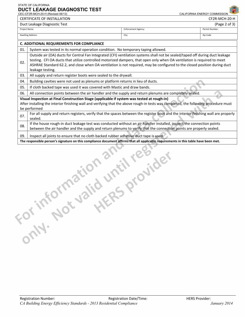
STATE OF CALIFORNIA
DUCT LEAKAGE DIAGNOSTIC TEST CEC-CF2R-MCH-20-H (Revised 06/13) CALIFORNIA ENERGY COMMISSION
CERTIFICATE OF INSTALLATION CF2R‐MCH‐20‐H Duct Leakage Diagnostic Test (Page 2 of 3) Project Name: Enforcement Agency: Permit Number:
Dwelling Address: City Zip Code
Registration Number: Registration Date/Time: HERS Provider: CA Building Energy Efficiency Standards - 2013 Residential Compliance January 2014
C. ADDITIONAL REQUIREMENTS FOR COMPLIANCE
01. System was tested in its normal operation condition. No temporary taping allowed.
02.
Outside air (OA) ducts for Central Fan Integrated (CFI) ventilation systems shall not be sealed/taped off during duct leakagetesting. CFI OA ducts that utilize controlled motorized dampers, that open only when OA ventilation is required to meet ASHRAE Standard 62.2, and close when OA ventilation is not required, may be configured to the closed position during duct leakage testing.
03. All supply and return register boots were sealed to the drywall.
04. Building cavities were not used as plenums or platform returns in lieu of ducts.
05. If cloth backed tape was used it was covered with Mastic and draw bands.
06. All connection points between the air handler and the supply and return plenums are completely sealed. Visual Inspection at Final Construction Stage (applicable if system was tested at rough‐in)After installing the interior finishing wall and verifying that the above rough‐in tests was completed, the following procedure must be performed
07. For all supply and return registers, verify that the spaces between the register boot and the interior finishing wall are properly sealed.
08. If the house rough‐in duct leakage test was conducted without an air handler installed, inspect the connection points between the air handler and the supply and return plenums to verify that the connection points are properly sealed.
09. Inspect all joints to ensure that no cloth backed rubber adhesive duct tape is used. The responsible person’s signature on this compliance document affirms that all applicable requirements in this table have been met.
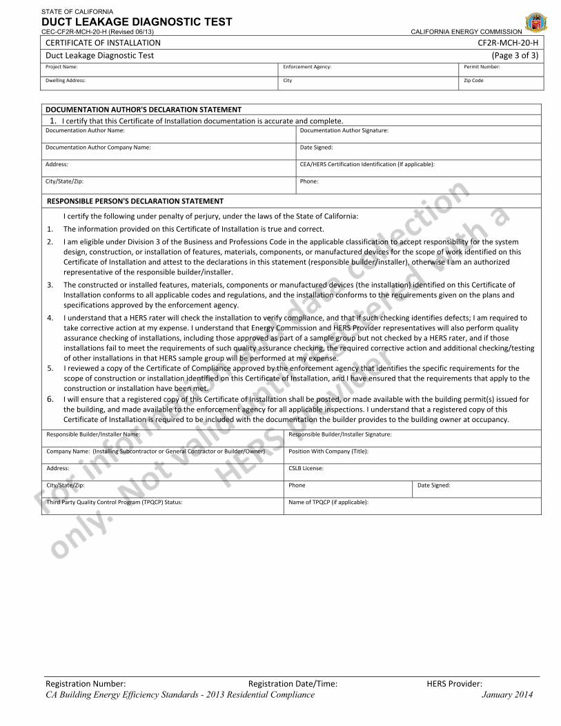
STATE OF CALIFORNIA
DUCT LEAKAGE DIAGNOSTIC TEST CEC-CF2R-MCH-20-H (Revised 06/13) CALIFORNIA ENERGY COMMISSION
CERTIFICATE OF INSTALLATION CF2R‐MCH‐20‐H Duct Leakage Diagnostic Test (Page 3 of 3) Project Name: Enforcement Agency: Permit Number:
Dwelling Address: City Zip Code
Registration Number: Registration Date/Time: HERS Provider: CA Building Energy Efficiency Standards - 2013 Residential Compliance January 2014
DOCUMENTATION AUTHOR'S DECLARATION STATEMENT1. I certify that this Certificate of Installation documentation is accurate and complete.
Documentation Author Name: Documentation Author Signature:
Documentation Author Company Name: Date Signed:
Address: CEA/HERS Certification Identification (If applicable):
City/State/Zip: Phone:
RESPONSIBLE PERSON'S DECLARATION STATEMENT
I certify the following under penalty of perjury, under the laws of the State of California:
1. The information provided on this Certificate of Installation is true and correct.
2. I am eligible under Division 3 of the Business and Professions Code in the applicable classification to accept responsibility for the system design, construction, or installation of features, materials, components, or manufactured devices for the scope of work identified on this Certificate of Installation and attest to the declarations in this statement (responsible builder/installer), otherwise I am an authorized representative of the responsible builder/installer.
3. The constructed or installed features, materials, components or manufactured devices (the installation) identified on this Certificate of Installation conforms to all applicable codes and regulations, and the installation conforms to the requirements given on the plans and specifications approved by the enforcement agency.
4. I understand that a HERS rater will check the installation to verify compliance, and that if such checking identifies defects; I am required to take corrective action at my expense. I understand that Energy Commission and HERS Provider representatives will also perform quality assurance checking of installations, including those approved as part of a sample group but not checked by a HERS rater, and if those installations fail to meet the requirements of such quality assurance checking, the required corrective action and additional checking/testing of other installations in that HERS sample group will be performed at my expense.
5. I reviewed a copy of the Certificate of Compliance approved by the enforcement agency that identifies the specific requirements for the scope of construction or installation identified on this Certificate of Installation, and I have ensured that the requirements that apply to the construction or installation have been met.
6. I will ensure that a registered copy of this Certificate of Installation shall be posted, or made available with the building permit(s) issued for the building, and made available to the enforcement agency for all applicable inspections. I understand that a registered copy of this Certificate of Installation is required to be included with the documentation the builder provides to the building owner at occupancy.
Responsible Builder/Installer Name: Responsible Builder/Installer Signature:
Company Name: (Installing Subcontractor or General Contractor or Builder/Owner) Position With Company (Title):
Address: CSLB License:
City/State/Zip: Phone Date Signed:
Third Party Quality Control Program (TPQCP) Status: Name of TPQCP (if applicable):
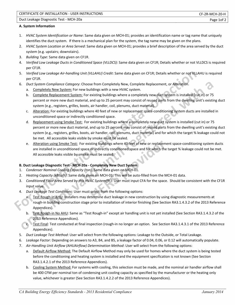
CERTIFICATE OF INSTALLATION ‐ USER INSTRUCTIONS CF‐2R‐MCH‐20‐H Duct Leakage Diagnostic Test ‐ MCH‐20a Page 1of 2
CA Building Energy Efficiency Standards - 2013 Residential Compliance January 2014
A. System Information 1. HVAC System Identification or Name: Same data given on MCH‐01; provides an identification name or tag name that uniquely
identifies the duct system. If there is a mechanical plan for the system, the tag name may be given on the plans. 2. HVAC System Location or Area Served: Same data given on MCH‐01; provides a brief description of the area served by the duct
system (e.g. upstairs; downstairs). 3. Building Type: Same data given on CF1R. 4. Verified Low Leakage Ducts in Conditioned Space (VLLDCS): Same data given on CF1R; Details whether or not VLLDCS is required
per CF1R. 5. Verified Low Leakage Air‐handling Unit (VLLAHU) Credit: Same data given on CF1R; Details whether or not VLLAHU is required
per CF1R. 6. Duct System Compliance Category: Choose from Completely New, Complete Replacement, or Alteration.
a. Completely New System: For new buildings with a new HVAC system. b. Complete Replacement System: For existing buildings where a completely new duct system is installed (cut in) or 75
percent or more new duct material, and up to 25 percent may consist of reused parts from the dwelling unit’s existing duct system (e.g., registers, grilles, boots, air handler, coil, plenums, duct material).
c. Alteration: For existing buildings where 40 feet of new or replacement space‐conditioning system ducts are installed in unconditioned space or indirectly conditioned space.
d. Replacement using Smoke Test: For existing buildings where a completely new duct system is installed (cut in) or 75 percent or more new duct material, and up to 25 percent may consist of reused parts from the dwelling unit’s existing duct system (e.g., registers, grilles, boots, air handler, coil, plenums, duct material) and for which the target % leakage could not be met. All accessible leaks visible by smoke must be sealed.
e. Alteration using Smoke Test: For existing buildings where 40 feet of new or replacement space‐conditioning system ducts are installed in unconditioned space or indirectly conditioned space and for which the target % leakage could not be met. All accessible leaks visible by smoke must be sealed.
B. Duct Leakage Diagnostic Test ‐ MCH‐20a ‐ Completely New Duct System 1. Condenser Nominal Cooling Capacity (ton): Same data given on MCH‐01. 2. Heating Capacity (kBtu/h): Same data given on MCH‐01; This will be auto‐filled from the MCH‐01 data. 3. Conditioned Floor Area Served by this HVAC System(ft2): User must input CFA for the space. Should be consistent with the CF1R
input value. 4. Duct Leakage Test Conditions: User must select from the following options:
a. Test Rough‐in AHU: Installers may determine duct leakage in new construction by using diagnostic measurements at rough‐in building construction stage prior to installation of interior finishing (See Section RA3.1.4.3.2 of the 2013 Reference Appendices).
b. Test Rough‐in No AHU: Same as “Test Rough‐in” except air handling unit is not yet installed (See Section RA3.1.4.3.2 of the 2013 Reference Appendices).
c. Test Final: Test conducted at final inspection (rough‐in no longer an option. See Section RA3.1.4.3.1 of the 2013 Reference Appendices).
5. Duct Leakage Test Method: User will select from the following options: Leakage to the Outside, or Total Leakage. 6. Leakage Factor: Depending on answers to A3, B4, and B5, a leakage factor of 0.04, 0.06, or 0.12 will automatically populate. 7. Air‐Handling Unit Airflow (AHUAirflow) Determination Method: User will select from the following options:
a. Default Airflow Method: The Default Airflow Method may only be used for homes where the duct system is being tested before the conditioning and heating system is installed and the equipment specification is not known (See Section RA3.1.4.2.1 of the 2013 Reference Appendices).
b. Cooling System Method: For systems with cooling, this selection must be made, and the nominal air handler airflow shall be 400 CFM per nominal ton of condensing unit cooling capacity as specified by the manufacturer or the heating only value, whichever is greater (See Section RA3.1.4.2.2 of the 2013 Reference Appendices).
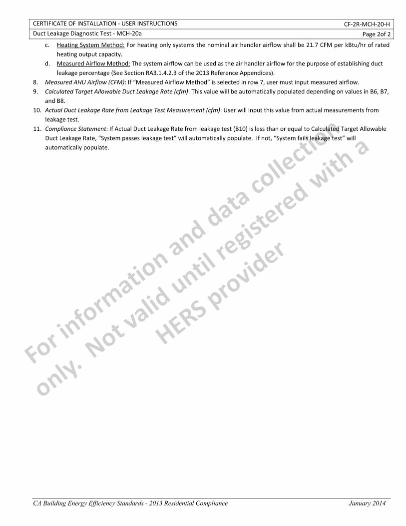
CERTIFICATE OF INSTALLATION ‐ USER INSTRUCTIONS CF‐2R‐MCH‐20‐H Duct Leakage Diagnostic Test ‐ MCH‐20a Page 2of 2
CA Building Energy Efficiency Standards - 2013 Residential Compliance January 2014
c. Heating System Method: For heating only systems the nominal air handler airflow shall be 21.7 CFM per kBtu/hr of rated heating output capacity.
d. Measured Airflow Method: The system airflow can be used as the air handler airflow for the purpose of establishing duct leakage percentage (See Section RA3.1.4.2.3 of the 2013 Reference Appendices).
8. Measured AHU Airflow (CFM): If “Measured Airflow Method” is selected in row 7, user must input measured airflow. 9. Calculated Target Allowable Duct Leakage Rate (cfm): This value will be automatically populated depending on values in B6, B7,
and B8. 10. Actual Duct Leakage Rate from Leakage Test Measurement (cfm): User will input this value from actual measurements from
leakage test. 11. Compliance Statement: If Actual Duct Leakage Rate from leakage test (B10) is less than or equal to Calculated Target Allowable
Duct Leakage Rate, “System passes leakage test” will automatically populate. If not, “System fails leakage test” will automatically populate.
CERTIFICATE OF INSTALLATION ‐ DATA FIELD DEFINITIONS AND CALCULATIONS CF‐2R‐MCH‐20‐H
Duct Leakage Diagnostic Test ‐ MCH‐20a Page 4of 4
CA Building Energy Efficiency Standards - 2013 Residential Compliance January 2014
1. I certify that this Certificate of Installation documentation is accurate and complete. Documentation Author Name: Documentation Author Signature:
Documentation Author Company Name: Date Signed:
Address: CEA/HERS Certification Identification (If applicable):
City/State/Zip: Phone:
RESPONSIBLE PERSON'S DECLARATION STATEMENT
I certify the following under penalty of perjury, under the laws of the State of California:
1. The information provided on this Certificate of Installation is true and correct.
2. I am eligible under Division 3 of the Business and Professions Code in the applicable classification to accept responsibility for the system design, construction, or installation of features, materials, components, or manufactured devices for the scope of work identified on this Certificate of Installation and attest to the declarations in this statement (responsible builder/installer), otherwise I am an authorized representative of the responsible builder/installer.
3. The constructed or installed features, materials, components or manufactured devices (the installation) identified on this Certificate of Installation conforms to all applicable codes and regulations, and the installation conforms to the requirements given on the plans and specifications approved by the enforcement agency.
4. I understand that a HERS rater will check the installation to verify compliance, and that if such checking identifies defects; I am required to take corrective action at my expense. I understand that Energy Commission and HERS Provider representatives will also perform quality assurance checking of installations, including those approved as part of a sample group but not checked by a HERS rater, and if those installations fail to meet the requirements of such quality assurance checking, the required corrective action and additional checking/testing of other installations in that HERS sample group will be performed at my expense.
5. I reviewed a copy of the Certificate of Compliance approved by the enforcement agency that identifies the specific requirements for the scope of construction or installation identified on this Certificate of Installation, and I have ensured that the requirements that apply to the construction or installation have been met.
6. I will ensure that a registered copy of this Certificate of Installation shall be posted, or made available with the building permit(s) issued for the building, and made available to the enforcement agency for all applicable inspections. I understand that a registered copy of this Certificate of Installation is required to be included with the documentation the builder provides to the building owner at occupancy.
Responsible Builder/Installer Name: Responsible Builder/Installer Signature:
Company Name: (Installing Subcontractor or General Contractor or Builder/Owner) Position With Company (Title):
Address: CSLB License:
City/State/Zip: Phone Date Signed:
Third Party Quality Control Program (TPQCP) Status: Name of TPQCP (if applicable):
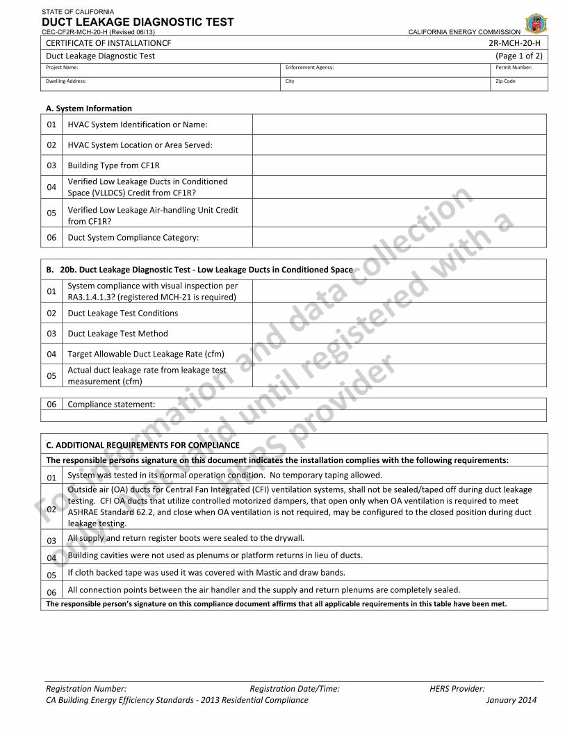
STATE OF CALIFORNIA
DUCT LEAKAGE DIAGNOSTIC TEST CEC-CF2R-MCH-20-H (Revised 06/13) CALIFORNIA ENERGY COMMISSION
CERTIFICATE OF INSTALLATIONCF 2R‐MCH‐20‐H Duct Leakage Diagnostic Test (Page 1 of 2) Project Name: Enforcement Agency: Permit Number:
Dwelling Address: City Zip Code
Registration Number: Registration Date/Time: HERS Provider: CA Building Energy Efficiency Standards ‐ 2013 Residential Compliance January 2014
A. System Information
01 HVAC System Identification or Name:
02 HVAC System Location or Area Served:
03 Building Type from CF1R
04 Verified Low Leakage Ducts in Conditioned Space (VLLDCS) Credit from CF1R?
05 Verified Low Leakage Air‐handling Unit Credit from CF1R?
06 Duct System Compliance Category:
B. 20b. Duct Leakage Diagnostic Test ‐ Low Leakage Ducts in Conditioned Space
01 System compliance with visual inspection per RA3.1.4.1.3? (registered MCH‐21 is required)
02 Duct Leakage Test Conditions
03 Duct Leakage Test Method
04 Target Allowable Duct Leakage Rate (cfm)
05 Actual duct leakage rate from leakage test measurement (cfm)
06 Compliance statement:
C. ADDITIONAL REQUIREMENTS FOR COMPLIANCE
The responsible persons signature on this document indicates the installation complies with the following requirements:
01 System was tested in its normal operation condition. No temporary taping allowed.
02
Outside air (OA) ducts for Central Fan Integrated (CFI) ventilation systems, shall not be sealed/taped off during duct leakage testing. CFI OA ducts that utilize controlled motorized dampers, that open only when OA ventilation is required to meet ASHRAE Standard 62.2, and close when OA ventilation is not required, may be configured to the closed position during duct leakage testing.
03 All supply and return register boots were sealed to the drywall.
04 Building cavities were not used as plenums or platform returns in lieu of ducts.
05 If cloth backed tape was used it was covered with Mastic and draw bands.
06 All connection points between the air handler and the supply and return plenums are completely sealed.
The responsible person’s signature on this compliance document affirms that all applicable requirements in this table have been met.

STATE OF CALIFORNIA
DUCT LEAKAGE DIAGNOSTIC TEST CEC-CF2R-MCH-20-H (Revised 06/13) CALIFORNIA ENERGY COMMISSION
CERTIFICATE OF INSTALLATIONCF 2R‐MCH‐20‐H Duct Leakage Diagnostic Test (Page 2 of 2) Project Name: Enforcement Agency: Permit Number:
Dwelling Address: City Zip Code
Registration Number: Registration Date/Time: HERS Provider: CA Building Energy Efficiency Standards ‐ 2013 Residential Compliance January 2014
DOCUMENTATION AUTHOR'S DECLARATION STATEMENT 1. I CERTIFY THAT THIS CERTIFICATE OF INSTALLATION DOCUMENTATION IS ACCURATE AND COMPLETE.
Documentation Author Name: Documentation Author Signature:
Documentation Author Company Name: Date Signed:
Address: CEA/HERS Certification Identification (If applicable):
City/State/Zip: Phone:
RESPONSIBLE PERSON'S DECLARATION STATEMENT
I certify the following under penalty of perjury, under the laws of the State of California:
1. The information provided on this Certificate of Installation is true and correct.
2. I am eligible under Division 3 of the Business and Professions Code in the applicable classification to accept responsibility for the system design, construction, or installation of features, materials, components, or manufactured devices for the scope of work identified on this Certificate of Installation and attest to the declarations in this statement (responsible builder/installer), otherwise I am an authorized representative of the responsible builder/installer.
3. The constructed or installed features, materials, components or manufactured devices (the installation) identified on this Certificate of Installation conforms to all applicable codes and regulations, and the installation conforms to the requirements given on the plans and specifications approved by the enforcement agency.
4. I understand that a HERS rater will check the installation to verify compliance, and that if such checking identifies defects; I am required to take corrective action at my expense. I understand that Energy Commission and HERS Provider representatives will also perform quality assurance checking of installations, including those approved as part of a sample group but not checked by a HERS rater, and if those installations fail to meet the requirements of such quality assurance checking, the required corrective action and additional checking/testing of other installations in that HERS sample group will be performed at my expense.
5. I reviewed a copy of the Certificate of Compliance approved by the enforcement agency that identifies the specific requirements for the scope of construction or installation identified on this Certificate of Installation, and I have ensured that the requirements that apply to the construction or installation have been met.
6. I will ensure that a registered copy of this Certificate of Installation shall be posted, or made available with the building permit(s) issued for the building, and made available to the enforcement agency for all applicable inspections. I understand that a registered copy of this Certificate of Installation is required to be included with the documentation the builder provides to the building owner at occupancy.
Responsible Builder/Installer Name: Responsible Builder/Installer Signature:
Company Name: (Installing Subcontractor or General Contractor or Builder/Owner) Position With Company (Title):
Address: CSLB License:
City/State/Zip: Phone Date Signed:
Third Party Quality Control Program (TPQCP) Status: Name of TPQCP (if applicable):
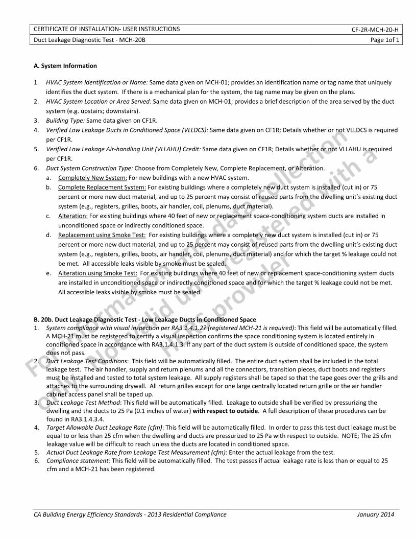
CERTIFICATE OF INSTALLATION‐ USER INSTRUCTIONS CF‐2R‐MCH‐20‐H
Duct Leakage Diagnostic Test ‐ MCH‐20B Page 1of 1
CA Building Energy Efficiency Standards ‐ 2013 Residential Compliance January 2014
A. System Information 1. HVAC System Identification or Name: Same data given on MCH‐01; provides an identification name or tag name that uniquely
identifies the duct system. If there is a mechanical plan for the system, the tag name may be given on the plans. 2. HVAC System Location or Area Served: Same data given on MCH‐01; provides a brief description of the area served by the duct
system (e.g. upstairs; downstairs). 3. Building Type: Same data given on CF1R. 4. Verified Low Leakage Ducts in Conditioned Space (VLLDCS): Same data given on CF1R; Details whether or not VLLDCS is required
per CF1R. 5. Verified Low Leakage Air‐handling Unit (VLLAHU) Credit: Same data given on CF1R; Details whether or not VLLAHU is required
per CF1R. 6. Duct System Construction Type: Choose from Completely New, Complete Replacement, or Alteration.
a. Completely New System: For new buildings with a new HVAC system. b. Complete Replacement System: For existing buildings where a completely new duct system is installed (cut in) or 75
percent or more new duct material, and up to 25 percent may consist of reused parts from the dwelling unit’s existing duct system (e.g., registers, grilles, boots, air handler, coil, plenums, duct material).
c. Alteration: For existing buildings where 40 feet of new or replacement space‐conditioning system ducts are installed in unconditioned space or indirectly conditioned space.
d. Replacement using Smoke Test: For existing buildings where a completely new duct system is installed (cut in) or 75 percent or more new duct material, and up to 25 percent may consist of reused parts from the dwelling unit’s existing duct system (e.g., registers, grilles, boots, air handler, coil, plenums, duct material) and for which the target % leakage could not be met. All accessible leaks visible by smoke must be sealed.
e. Alteration using Smoke Test: For existing buildings where 40 feet of new or replacement space‐conditioning system ducts are installed in unconditioned space or indirectly conditioned space and for which the target % leakage could not be met. All accessible leaks visible by smoke must be sealed.
B. 20b. Duct Leakage Diagnostic Test ‐ Low Leakage Ducts in Conditioned Space 1. System compliance with visual inspection per RA3.1.4.1.2? (registered MCH‐21 is required): This field will be automatically filled.
A MCH‐21 must be registered to certify a visual inspection confirms the space conditioning system is located entirely in conditioned space in accordance with RA3.1.4.1.3. If any part of the duct system is outside of conditioned space, the system does not pass.
2. Duct Leakage Test Conditions: This field will be automatically filled. The entire duct system shall be included in the total leakage test. The air handler, supply and return plenums and all the connectors, transition pieces, duct boots and registers must be installed and tested to total system leakage. All supply registers shall be taped so that the tape goes over the grills and attaches to the surrounding drywall. All return grilles except for one large centrally located return grille or the air handler cabinet access panel shall be taped up.
3. Duct Leakage Test Method: This field will be automatically filled. Leakage to outside shall be verified by pressurizing the dwelling and the ducts to 25 Pa (0.1 inches of water) with respect to outside. A full description of these procedures can be found in RA3.1.4.3.4.
4. Target Allowable Duct Leakage Rate (cfm): This field will be automatically filled. In order to pass this test duct leakage must be equal to or less than 25 cfm when the dwelling and ducts are pressurized to 25 Pa with respect to outside. NOTE; The 25 cfm leakage value will be difficult to reach unless the ducts are located in conditioned space.
5. Actual Duct Leakage Rate from Leakage Test Measurement (cfm): Enter the actual leakage from the test. 6. Compliance statement: This field will be automatically filled. The test passes if actual leakage rate is less than or equal to 25
cfm and a MCH‐21 has been registered.
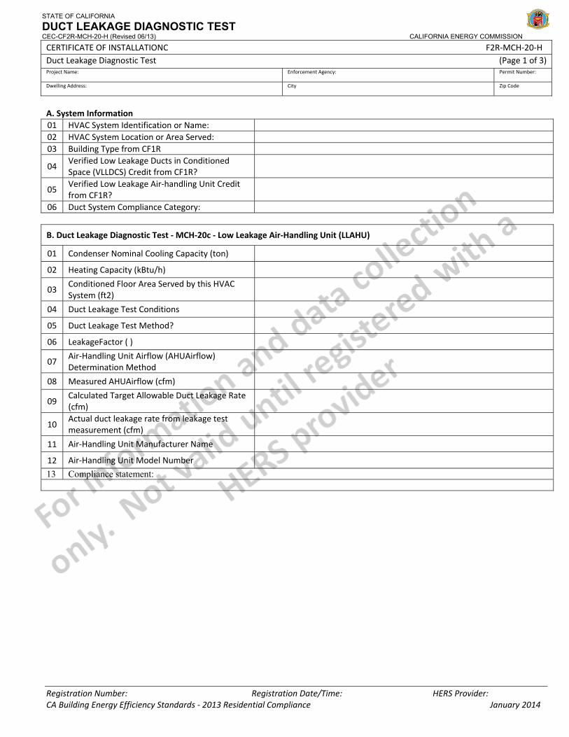
STATE OF CALIFORNIA
DUCT LEAKAGE DIAGNOSTIC TEST CEC-CF2R-MCH-20-H (Revised 06/13) CALIFORNIA ENERGY COMMISSION
CERTIFICATE OF INSTALLATIONC F2R‐MCH‐20‐H Duct Leakage Diagnostic Test (Page 1 of 3) Project Name: Enforcement Agency: Permit Number:
Dwelling Address: City Zip Code
Registration Number: Registration Date/Time: HERS Provider: CA Building Energy Efficiency Standards ‐ 2013 Residential Compliance January 2014
A. System Information 01 HVAC System Identification or Name: 02 HVAC System Location or Area Served: 03 Building Type from CF1R
04 Verified Low Leakage Ducts in Conditioned Space (VLLDCS) Credit from CF1R?
05 Verified Low Leakage Air‐handling Unit Credit from CF1R?
06 Duct System Compliance Category:
B. Duct Leakage Diagnostic Test ‐ MCH‐20c ‐ Low Leakage Air‐Handling Unit (LLAHU)
01 Condenser Nominal Cooling Capacity (ton)
02 Heating Capacity (kBtu/h)
03 Conditioned Floor Area Served by this HVAC System (ft2)
04 Duct Leakage Test Conditions
05 Duct Leakage Test Method?
06 LeakageFactor ( )
07 Air‐Handling Unit Airflow (AHUAirflow) Determination Method
08 Measured AHUAirflow (cfm)
09 Calculated Target Allowable Duct Leakage Rate (cfm)
10 Actual duct leakage rate from leakage test measurement (cfm)
11 Air‐Handling Unit Manufacturer Name
12 Air‐Handling Unit Model Number
13 Compliance statement:
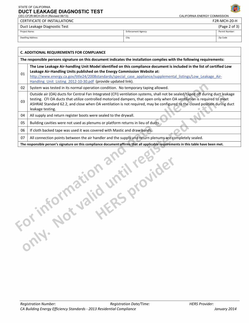
STATE OF CALIFORNIA
DUCT LEAKAGE DIAGNOSTIC TEST CEC-CF2R-MCH-20-H (Revised 06/13) CALIFORNIA ENERGY COMMISSION
CERTIFICATE OF INSTALLATIONC F2R‐MCH‐20‐H Duct Leakage Diagnostic Test (Page 2 of 3) Project Name: Enforcement Agency: Permit Number:
Dwelling Address: City Zip Code
Registration Number: Registration Date/Time: HERS Provider: CA Building Energy Efficiency Standards ‐ 2013 Residential Compliance January 2014
C. ADDITIONAL REQUIREMENTS FOR COMPLIANCE
The responsible persons signature on this document indicates the installation complies with the following requirements:
01
The Low Leakage Air‐handling Unit Model identified on this compliance document is included in the list of certified Low Leakage Air‐Handling Units published on the Energy Commission Website at: http://www.energy.ca.gov/title24/2008standards/special_case_appliance/supplemental_listings/Low_Leakage_Air‐Handling_Unit_Listing_2012‐10‐30.pdf (provide updated link).
02 System was tested in its normal operation condition. No temporary taping allowed.
03
Outside air (OA) ducts for Central Fan Integrated (CFI) ventilation systems, shall not be sealed/taped off during duct leakage testing. CFI OA ducts that utilize controlled motorized dampers, that open only when OA ventilation is required to meet ASHRAE Standard 62.2, and close when OA ventilation is not required, may be configured to the closed position during duct leakage testing.
04 All supply and return register boots were sealed to the drywall.
05 Building cavities were not used as plenums or platform returns in lieu of ducts.
06 If cloth backed tape was used it was covered with Mastic and draw bands.
07 All connection points between the air handler and the supply and return plenums are completely sealed.
The responsible person’s signature on this compliance document affirms that all applicable requirements in this table have been met.
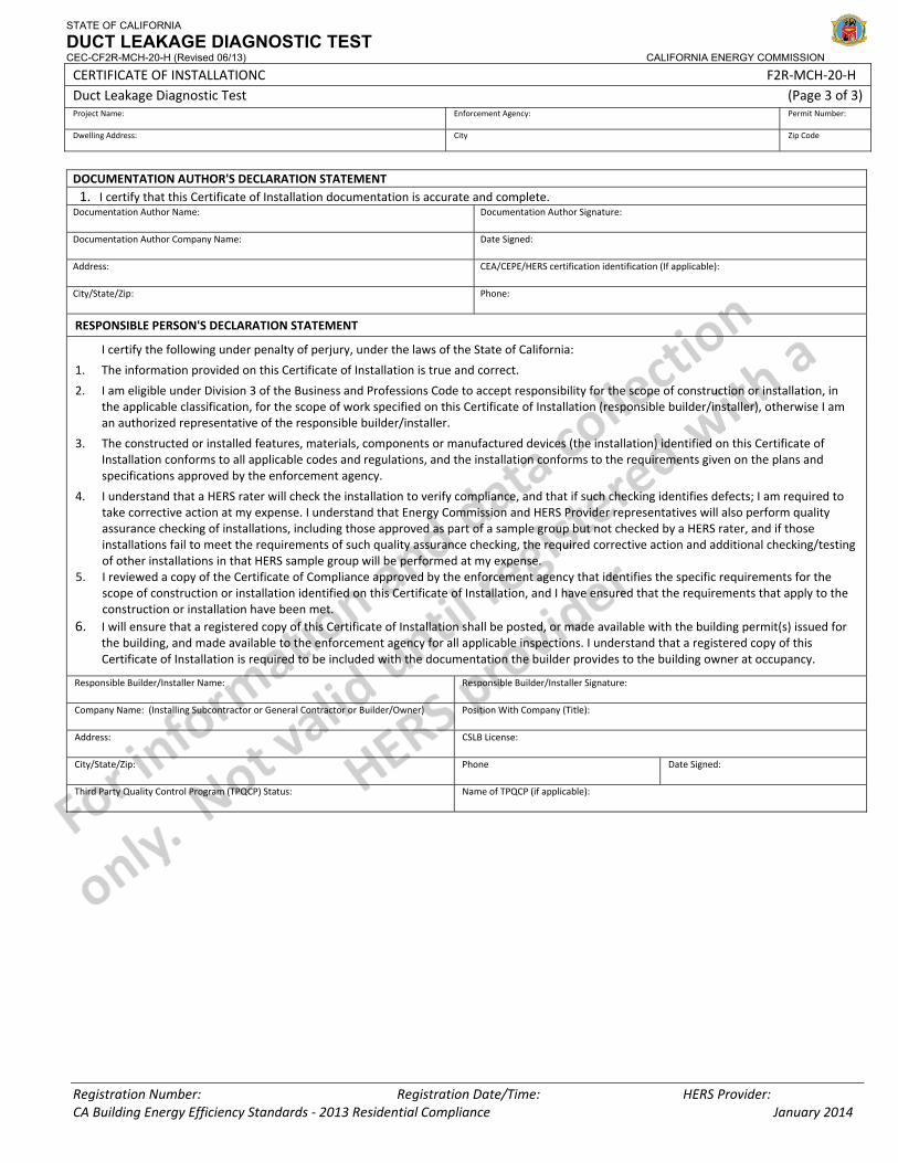
STATE OF CALIFORNIA
DUCT LEAKAGE DIAGNOSTIC TEST CEC-CF2R-MCH-20-H (Revised 06/13) CALIFORNIA ENERGY COMMISSION
CERTIFICATE OF INSTALLATIONC F2R‐MCH‐20‐H Duct Leakage Diagnostic Test (Page 3 of 3) Project Name: Enforcement Agency: Permit Number:
Dwelling Address: City Zip Code
Registration Number: Registration Date/Time: HERS Provider: CA Building Energy Efficiency Standards ‐ 2013 Residential Compliance January 2014
DOCUMENTATION AUTHOR'S DECLARATION STATEMENT1. I certify that this Certificate of Installation documentation is accurate and complete.
Documentation Author Name: Documentation Author Signature:
Documentation Author Company Name: Date Signed:
Address: CEA/CEPE/HERS certification identification (If applicable):
City/State/Zip: Phone:
RESPONSIBLE PERSON'S DECLARATION STATEMENT
I certify the following under penalty of perjury, under the laws of the State of California:
1. The information provided on this Certificate of Installation is true and correct.
2. I am eligible under Division 3 of the Business and Professions Code to accept responsibility for the scope of construction or installation, in the applicable classification, for the scope of work specified on this Certificate of Installation (responsible builder/installer), otherwise I am an authorized representative of the responsible builder/installer.
3. The constructed or installed features, materials, components or manufactured devices (the installation) identified on this Certificate of Installation conforms to all applicable codes and regulations, and the installation conforms to the requirements given on the plans and specifications approved by the enforcement agency.
4. I understand that a HERS rater will check the installation to verify compliance, and that if such checking identifies defects; I am required to take corrective action at my expense. I understand that Energy Commission and HERS Provider representatives will also perform quality assurance checking of installations, including those approved as part of a sample group but not checked by a HERS rater, and if those installations fail to meet the requirements of such quality assurance checking, the required corrective action and additional checking/testing of other installations in that HERS sample group will be performed at my expense.
5. I reviewed a copy of the Certificate of Compliance approved by the enforcement agency that identifies the specific requirements for the scope of construction or installation identified on this Certificate of Installation, and I have ensured that the requirements that apply to the construction or installation have been met.
6. I will ensure that a registered copy of this Certificate of Installation shall be posted, or made available with the building permit(s) issued for the building, and made available to the enforcement agency for all applicable inspections. I understand that a registered copy of this Certificate of Installation is required to be included with the documentation the builder provides to the building owner at occupancy.
Responsible Builder/Installer Name: Responsible Builder/Installer Signature:
Company Name: (Installing Subcontractor or General Contractor or Builder/Owner) Position With Company (Title):
Address: CSLB License:
City/State/Zip: Phone Date Signed:
Third Party Quality Control Program (TPQCP) Status: Name of TPQCP (if applicable):
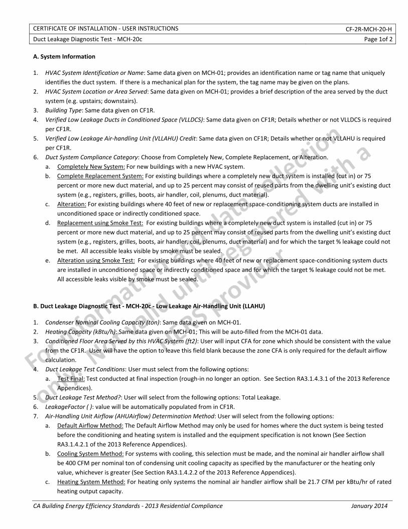
CERTIFICATE OF INSTALLATION ‐ USER INSTRUCTIONS CF‐2R‐MCH‐20‐H
Duct Leakage Diagnostic Test ‐ MCH‐20c Page 1of 2
CA Building Energy Efficiency Standards ‐ 2013 Residential Compliance January 2014
A. System Information 1. HVAC System Identification or Name: Same data given on MCH‐01; provides an identification name or tag name that uniquely
identifies the duct system. If there is a mechanical plan for the system, the tag name may be given on the plans. 2. HVAC System Location or Area Served: Same data given on MCH‐01; provides a brief description of the area served by the duct
system (e.g. upstairs; downstairs). 3. Building Type: Same data given on CF1R. 4. Verified Low Leakage Ducts in Conditioned Space (VLLDCS): Same data given on CF1R; Details whether or not VLLDCS is required
per CF1R. 5. Verified Low Leakage Air‐handling Unit (VLLAHU) Credit: Same data given on CF1R; Details whether or not VLLAHU is required
per CF1R. 6. Duct System Compliance Category: Choose from Completely New, Complete Replacement, or Alteration.
a. Completely New System: For new buildings with a new HVAC system. b. Complete Replacement System: For existing buildings where a completely new duct system is installed (cut in) or 75
percent or more new duct material, and up to 25 percent may consist of reused parts from the dwelling unit’s existing duct system (e.g., registers, grilles, boots, air handler, coil, plenums, duct material).
c. Alteration: For existing buildings where 40 feet of new or replacement space‐conditioning system ducts are installed in unconditioned space or indirectly conditioned space.
d. Replacement using Smoke Test: For existing buildings where a completely new duct system is installed (cut in) or 75 percent or more new duct material, and up to 25 percent may consist of reused parts from the dwelling unit’s existing duct system (e.g., registers, grilles, boots, air handler, coil, plenums, duct material) and for which the target % leakage could not be met. All accessible leaks visible by smoke must be sealed.
e. Alteration using Smoke Test: For existing buildings where 40 feet of new or replacement space‐conditioning system ducts are installed in unconditioned space or indirectly conditioned space and for which the target % leakage could not be met. All accessible leaks visible by smoke must be sealed.
B. Duct Leakage Diagnostic Test ‐ MCH‐20c ‐ Low Leakage Air‐Handling Unit (LLAHU) 1. Condenser Nominal Cooling Capacity (ton): Same data given on MCH‐01. 2. Heating Capacity (kBtu/h): Same data given on MCH‐01; This will be auto‐filled from the MCH‐01 data. 3. Conditioned Floor Area Served by this HVAC System (ft2): User will input CFA for zone which should be consistent with the value
from the CF1R. User will have the option to leave this field blank because the zone CFA is only required for the default airflow calculation.
4. Duct Leakage Test Conditions: User must select from the following options: a. Test Final: Test conducted at final inspection (rough‐in no longer an option. See Section RA3.1.4.3.1 of the 2013 Reference
Appendices). 5. Duct Leakage Test Method?: User will select from the following options: Total Leakage. 6. LeakageFactor ( ): value will be automatically populated from in CF1R. 7. Air‐Handling Unit Airflow (AHUAirflow) Determination Method: User will select from the following options:
a. Default Airflow Method: The Default Airflow Method may only be used for homes where the duct system is being tested before the conditioning and heating system is installed and the equipment specification is not known (See Section RA3.1.4.2.1 of the 2013 Reference Appendices).
b. Cooling System Method: For systems with cooling, this selection must be made, and the nominal air handler airflow shall be 400 CFM per nominal ton of condensing unit cooling capacity as specified by the manufacturer or the heating only value, whichever is greater (See Section RA3.1.4.2.2 of the 2013 Reference Appendices).
c. Heating System Method: For heating only systems the nominal air handler airflow shall be 21.7 CFM per kBtu/hr of rated heating output capacity.
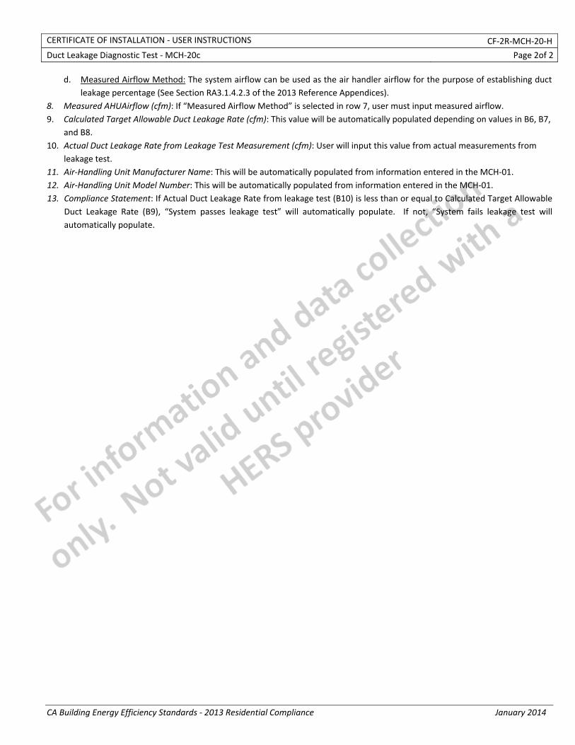
CERTIFICATE OF INSTALLATION ‐ USER INSTRUCTIONS CF‐2R‐MCH‐20‐H
Duct Leakage Diagnostic Test ‐ MCH‐20c Page 2of 2
CA Building Energy Efficiency Standards ‐ 2013 Residential Compliance January 2014
d. Measured Airflow Method: The system airflow can be used as the air handler airflow for the purpose of establishing duct leakage percentage (See Section RA3.1.4.2.3 of the 2013 Reference Appendices).
8. Measured AHUAirflow (cfm): If “Measured Airflow Method” is selected in row 7, user must input measured airflow. 9. Calculated Target Allowable Duct Leakage Rate (cfm): This value will be automatically populated depending on values in B6, B7,
and B8. 10. Actual Duct Leakage Rate from Leakage Test Measurement (cfm): User will input this value from actual measurements from
leakage test. 11. Air‐Handling Unit Manufacturer Name: This will be automatically populated from information entered in the MCH‐01. 12. Air‐Handling Unit Model Number: This will be automatically populated from information entered in the MCH‐01. 13. Compliance Statement: If Actual Duct Leakage Rate from leakage test (B10) is less than or equal to Calculated Target Allowable
Duct Leakage Rate (B9), “System passes leakage test” will automatically populate. If not, “System fails leakage test will automatically populate.
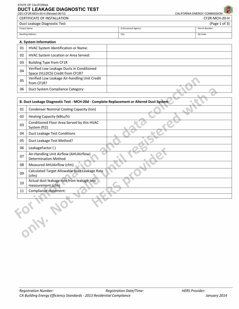
STATE OF CALIFORNIA
DUCT LEAKAGE DIAGNOSTIC TEST CEC-CF2R-MCH-20-H (Revised 06/13) CALIFORNIA ENERGY COMMISSION
CERTIFICATE OF INSTALLATION CF2R‐MCH‐20‐H Duct Leakage Diagnostic Test (Page 1 of 3) Project Name: Enforcement Agency: Permit Number:
Dwelling Address: City Zip Code
Registration Number: Registration Date/Time: HERS Provider: CA Building Energy Efficiency Standards ‐ 2013 Residential Compliance January 2014
A. System Information
01 HVAC System Identification or Name:
02 HVAC System Location or Area Served:
03 Building Type from CF1R
04 Verified Low Leakage Ducts in Conditioned Space (VLLDCS) Credit from CF1R?
05 Verified Low Leakage Air‐handling Unit Credit from CF1R?
06 Duct System Compliance Category:
B. Duct Leakage Diagnostic Test ‐ MCH‐20d ‐ Complete Replacement or Altered Duct System
01 Condenser Nominal Cooling Capacity (ton)
02 Heating Capacity (kBtu/h)
03 Conditioned Floor Area Served by this HVAC System (ft2)
04 Duct Leakage Test Conditions
05 Duct Leakage Test Method?
06 LeakageFactor ( )
07 Air‐Handling Unit Airflow (AHUAirflow) Determination Method
08 Measured AHUAirflow (cfm)
09 Calculated Target Allowable Duct Leakage Rate (cfm)
10 Actual duct leakage rate from leakage test measurement (cfm)
11 Compliance statement:
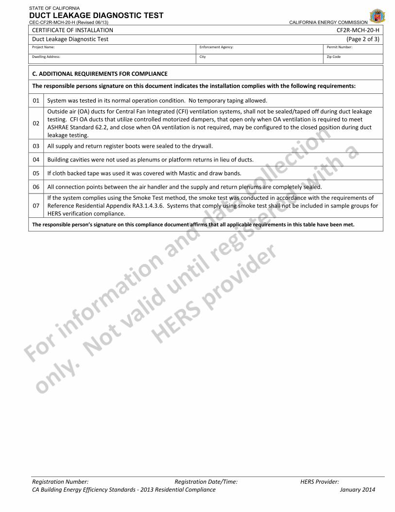
STATE OF CALIFORNIA
DUCT LEAKAGE DIAGNOSTIC TEST CEC-CF2R-MCH-20-H (Revised 06/13) CALIFORNIA ENERGY COMMISSION
CERTIFICATE OF INSTALLATION CF2R‐MCH‐20‐H Duct Leakage Diagnostic Test (Page 2 of 3) Project Name: Enforcement Agency: Permit Number:
Dwelling Address: City Zip Code
Registration Number: Registration Date/Time: HERS Provider: CA Building Energy Efficiency Standards ‐ 2013 Residential Compliance January 2014
C. ADDITIONAL REQUIREMENTS FOR COMPLIANCE
The responsible persons signature on this document indicates the installation complies with the following requirements:
01 System was tested in its normal operation condition. No temporary taping allowed.
02
Outside air (OA) ducts for Central Fan Integrated (CFI) ventilation systems, shall not be sealed/taped off during duct leakage testing. CFI OA ducts that utilize controlled motorized dampers, that open only when OA ventilation is required to meet ASHRAE Standard 62.2, and close when OA ventilation is not required, may be configured to the closed position during duct leakage testing.
03 All supply and return register boots were sealed to the drywall.
04 Building cavities were not used as plenums or platform returns in lieu of ducts.
05 If cloth backed tape was used it was covered with Mastic and draw bands.
06 All connection points between the air handler and the supply and return plenums are completely sealed.
07 If the system complies using the Smoke Test method, the smoke test was conducted in accordance with the requirements of Reference Residential Appendix RA3.1.4.3.6. Systems that comply using smoke test shall not be included in sample groups for HERS verification compliance.
The responsible person’s signature on this compliance document affirms that all applicable requirements in this table have been met.

STATE OF CALIFORNIA
DUCT LEAKAGE DIAGNOSTIC TEST CEC-CF2R-MCH-20-H (Revised 06/13) CALIFORNIA ENERGY COMMISSION
CERTIFICATE OF INSTALLATION CF2R‐MCH‐20‐H Duct Leakage Diagnostic Test (Page 3 of 3) Project Name: Enforcement Agency: Permit Number:
Dwelling Address: City Zip Code
Registration Number: Registration Date/Time: HERS Provider: CA Building Energy Efficiency Standards ‐ 2013 Residential Compliance January 2014
DOCUMENTATION AUTHOR'S DECLARATION STATEMENT 1. I CERTIFY THAT THIS CERTIFICATE OF INSTALLATION DOCUMENTATION IS ACCURATE AND COMPLETE.
Documentation Author Name: Documentation Author Signature:
Documentation Author Company Name: Date Signed:
Address: CEA/HERS Certification Identification (If applicable):
City/State/Zip: Phone:
RESPONSIBLE PERSON'S DECLARATION STATEMENT
I certify the following under penalty of perjury, under the laws of the State of California:
1. The information provided on this Certificate of Installation is true and correct.
2. I am eligible under Division 3 of the Business and Professions Code in the applicable classification to accept responsibility for the system design, construction, or installation of features, materials, components, or manufactured devices for the scope of work identified on this Certificate of Installation and attest to the declarations in this statement (responsible builder/installer), otherwise I am an authorized representative of the responsible builder/installer.
3. The constructed or installed features, materials, components or manufactured devices (the installation) identified on this Certificate of Installation conforms to all applicable codes and regulations, and the installation conforms to the requirements given on the plans and specifications approved by the enforcement agency.
4. I understand that a HERS rater will check the installation to verify compliance, and that if such checking identifies defects; I am required to take corrective action at my expense. I understand that Energy Commission and HERS Provider representatives will also perform quality assurance checking of installations, including those approved as part of a sample group but not checked by a HERS rater, and if those installations fail to meet the requirements of such quality assurance checking, the required corrective action and additional checking/testing of other installations in that HERS sample group will be performed at my expense.
5. I reviewed a copy of the Certificate of Compliance approved by the enforcement agency that identifies the specific requirements for the scope of construction or installation identified on this Certificate of Installation, and I have ensured that the requirements that apply to the construction or installation have been met.
6. I will ensure that a registered copy of this Certificate of Installation shall be posted, or made available with the building permit(s) issued for the building, and made available to the enforcement agency for all applicable inspections. I understand that a registered copy of this Certificate of Installation is required to be included with the documentation the builder provides to the building owner at occupancy.
Responsible Builder/Installer Name: Responsible Builder/Installer Signature:
Company Name: (Installing Subcontractor or General Contractor or Builder/Owner) Position With Company (Title):
Address: CSLB License:
City/State/Zip: Phone Date Signed:
Third Party Quality Control Program (TPQCP) Status: Name of TPQCP (if applicable):
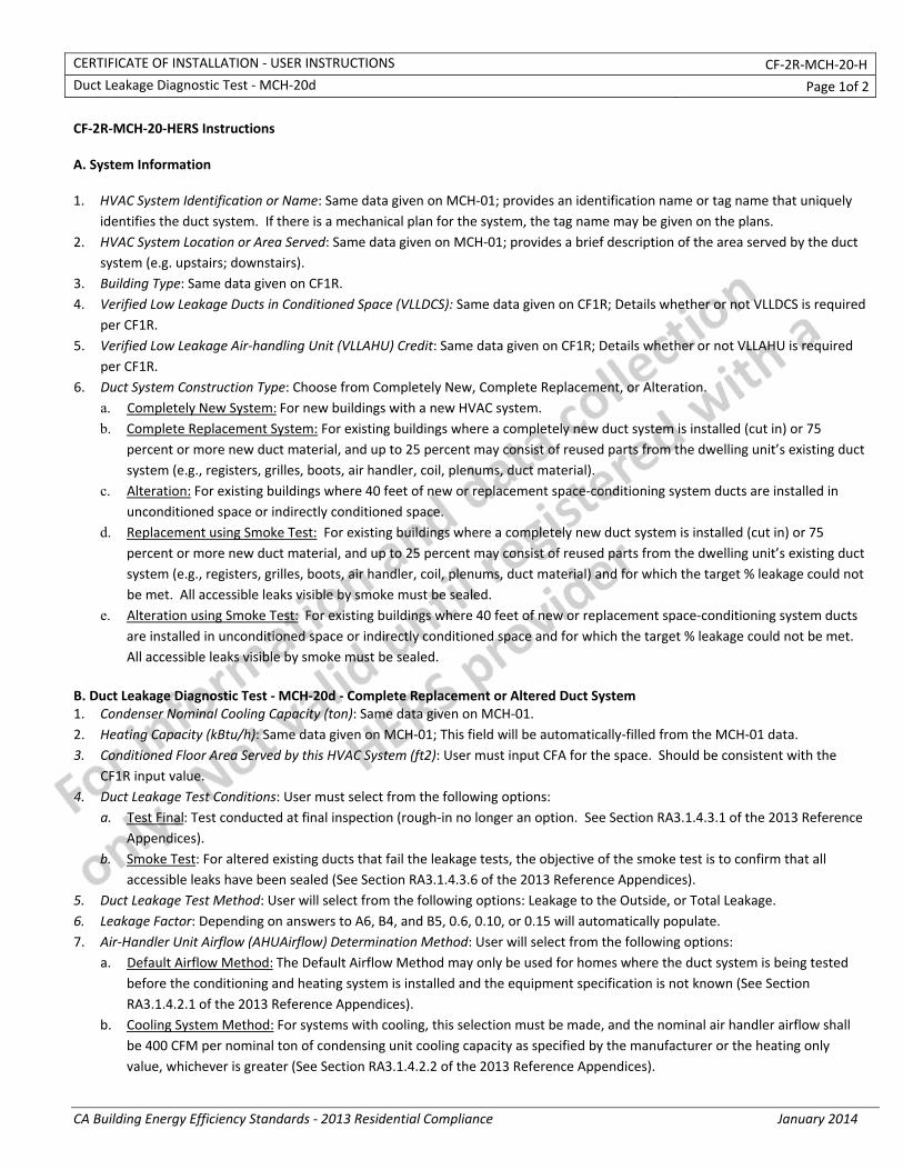
CERTIFICATE OF INSTALLATION ‐ USER INSTRUCTIONS CF‐2R‐MCH‐20‐H Duct Leakage Diagnostic Test ‐ MCH‐20d Page 1of 2
CA Building Energy Efficiency Standards ‐ 2013 Residential Compliance January 2014
CF‐2R‐MCH‐20‐HERS Instructions A. System Information 1. HVAC System Identification or Name: Same data given on MCH‐01; provides an identification name or tag name that uniquely
identifies the duct system. If there is a mechanical plan for the system, the tag name may be given on the plans. 2. HVAC System Location or Area Served: Same data given on MCH‐01; provides a brief description of the area served by the duct
system (e.g. upstairs; downstairs). 3. Building Type: Same data given on CF1R. 4. Verified Low Leakage Ducts in Conditioned Space (VLLDCS): Same data given on CF1R; Details whether or not VLLDCS is required
per CF1R. 5. Verified Low Leakage Air‐handling Unit (VLLAHU) Credit: Same data given on CF1R; Details whether or not VLLAHU is required
per CF1R. 6. Duct System Construction Type: Choose from Completely New, Complete Replacement, or Alteration.
a. Completely New System: For new buildings with a new HVAC system. b. Complete Replacement System: For existing buildings where a completely new duct system is installed (cut in) or 75
percent or more new duct material, and up to 25 percent may consist of reused parts from the dwelling unit’s existing duct system (e.g., registers, grilles, boots, air handler, coil, plenums, duct material).
c. Alteration: For existing buildings where 40 feet of new or replacement space‐conditioning system ducts are installed in unconditioned space or indirectly conditioned space.
d. Replacement using Smoke Test: For existing buildings where a completely new duct system is installed (cut in) or 75 percent or more new duct material, and up to 25 percent may consist of reused parts from the dwelling unit’s existing duct system (e.g., registers, grilles, boots, air handler, coil, plenums, duct material) and for which the target % leakage could not be met. All accessible leaks visible by smoke must be sealed.
e. Alteration using Smoke Test: For existing buildings where 40 feet of new or replacement space‐conditioning system ducts are installed in unconditioned space or indirectly conditioned space and for which the target % leakage could not be met. All accessible leaks visible by smoke must be sealed.
B. Duct Leakage Diagnostic Test ‐ MCH‐20d ‐ Complete Replacement or Altered Duct System 1. Condenser Nominal Cooling Capacity (ton): Same data given on MCH‐01. 2. Heating Capacity (kBtu/h): Same data given on MCH‐01; This field will be automatically‐filled from the MCH‐01 data. 3. Conditioned Floor Area Served by this HVAC System (ft2): User must input CFA for the space. Should be consistent with the
CF1R input value. 4. Duct Leakage Test Conditions: User must select from the following options:
a. Test Final: Test conducted at final inspection (rough‐in no longer an option. See Section RA3.1.4.3.1 of the 2013 Reference Appendices).
b. Smoke Test: For altered existing ducts that fail the leakage tests, the objective of the smoke test is to confirm that all accessible leaks have been sealed (See Section RA3.1.4.3.6 of the 2013 Reference Appendices).
5. Duct Leakage Test Method: User will select from the following options: Leakage to the Outside, or Total Leakage. 6. Leakage Factor: Depending on answers to A6, B4, and B5, 0.6, 0.10, or 0.15 will automatically populate. 7. Air‐Handler Unit Airflow (AHUAirflow) Determination Method: User will select from the following options:
a. Default Airflow Method: The Default Airflow Method may only be used for homes where the duct system is being tested before the conditioning and heating system is installed and the equipment specification is not known (See Section RA3.1.4.2.1 of the 2013 Reference Appendices).
b. Cooling System Method: For systems with cooling, this selection must be made, and the nominal air handler airflow shall be 400 CFM per nominal ton of condensing unit cooling capacity as specified by the manufacturer or the heating only value, whichever is greater (See Section RA3.1.4.2.2 of the 2013 Reference Appendices).
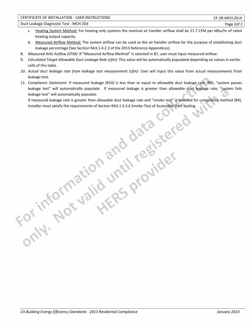
CERTIFICATE OF INSTALLATION ‐ USER INSTRUCTIONS CF‐2R‐MCH‐20‐H Duct Leakage Diagnostic Test ‐ MCH‐20d Page 2of 2
CA Building Energy Efficiency Standards ‐ 2013 Residential Compliance January 2014
c. Heating System Method: For heating only systems the nominal air handler airflow shall be 21.7 CFM per kBtu/hr of rated heating output capacity.
d. Measured Airflow Method: The system airflow can be used as the air handler airflow for the purpose of establishing duct leakage percentage (See Section RA3.1.4.2.3 of the 2013 Reference Appendices).
8. Measured AHU Airflow (CFM): If “Measured Airflow Method” is selected in B7, user must input measured airflow. 9. Calculated Target Allowable Duct Leakage Rate (cfm): This value will be automatically populated depending on values in earlier
cells of this table. 10. Actual duct leakage rate from leakage test measurement (cfm): User will input this value from actual measurements from
leakage test. 11. Compliance Statement: If measured leakage (B10) is less than or equal to allowable duct leakage rate (B9), “system passes
leakage test” will automatically populate. If measured leakage is greater than allowable duct leakage rate, “system fails leakage test” will automatically populate. If measured leakage rate is greater than allowable duct leakage rate and “smoke test” is selected for compliance method (B4), Installer must satisfy the requirements of Section RA3.1.4.3.6 Smoke‐Test of Accessible Duct Sealing.
CERTIFICATE OF INSTALLATION ‐ DATA FIELD DEFINITIONS AND CALCULATIONS CF‐2R‐MCH‐20‐H Duct Leakage Diagnostic Test ‐ MCH‐20d Page 4of 4
CA Building Energy Efficiency Standards ‐ 2013 Residential Compliance January 2014
1. I CERTIFY THAT THIS CERTIFICATE OF INSTALLATION DOCUMENTATION IS ACCURATE AND COMPLETE. Documentation Author Name: Documentation Author Signature:
Documentation Author Company Name: Date Signed:
Address: CEA/HERS Certification Identification (If applicable):
City/State/Zip: Phone:
RESPONSIBLE PERSON'S DECLARATION STATEMENT
I certify the following under penalty of perjury, under the laws of the State of California:
1. The information provided on this Certificate of Installation is true and correct.
2. I am eligible under Division 3 of the Business and Professions Code in the applicable classification to accept responsibility for the system design, construction, or installation of features, materials, components, or manufactured devices for the scope of work identified on this Certificate of Installation and attest to the declarations in this statement (responsible builder/installer), otherwise I am an authorized representative of the responsible builder/installer.
3. The constructed or installed features, materials, components or manufactured devices (the installation) identified on this Certificate of Installation conforms to all applicable codes and regulations, and the installation conforms to the requirements given on the plans and specifications approved by the enforcement agency.
4. I understand that a HERS rater will check the installation to verify compliance, and that if such checking identifies defects; I am required to take corrective action at my expense. I understand that Energy Commission and HERS Provider representatives will also perform quality assurance checking of installations, including those approved as part of a sample group but not checked by a HERS rater, and if those installations fail to meet the requirements of such quality assurance checking, the required corrective action and additional checking/testing of other installations in that HERS sample group will be performed at my expense.
5. I reviewed a copy of the Certificate of Compliance approved by the enforcement agency that identifies the specific requirements for the scope of construction or installation identified on this Certificate of Installation, and I have ensured that the requirements that apply to the construction or installation have been met.
6. I will ensure that a registered copy of this Certificate of Installation shall be posted, or made available with the building permit(s) issued for the building, and made available to the enforcement agency for all applicable inspections. I understand that a registered copy of this Certificate of Installation is required to be included with the documentation the builder provides to the building owner at occupancy.
Responsible Builder/Installer Name: Responsible Builder/Installer Signature:
Company Name: (Installing Subcontractor or General Contractor or Builder/Owner) Position With Company (Title):
Address: CSLB License:
City/State/Zip: Phone Date Signed:
Third Party Quality Control Program (TPQCP) Status: Name of TPQCP (if applicable):
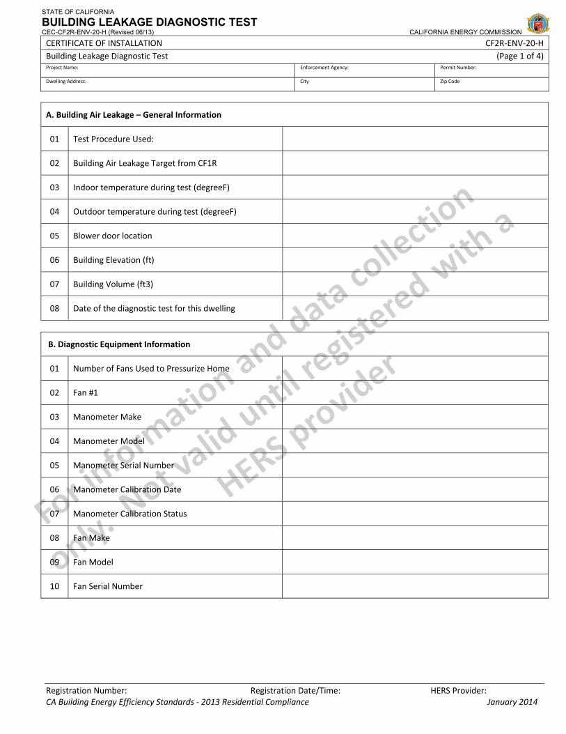
STATE OF CALIFORNIA
BUILDING LEAKAGE DIAGNOSTIC TEST CEC-CF2R-ENV-20-H (Revised 06/13) CALIFORNIA ENERGY COMMISSION
CERTIFICATE OF INSTALLATION CF2R‐ENV‐20‐H Building Leakage Diagnostic Test (Page 1 of 4) Project Name: Enforcement Agency: Permit Number:
Dwelling Address: City Zip Code
Registration Number: Registration Date/Time: HERS Provider: CA Building Energy Efficiency Standards ‐ 2013 Residential Compliance January 2014
A. Building Air Leakage – General Information
01 Test Procedure Used:
02 Building Air Leakage Target from CF1R
03 Indoor temperature during test (degreeF)
04 Outdoor temperature during test (degreeF)
05 Blower door location
06 Building Elevation (ft)
07 Building Volume (ft3)
08 Date of the diagnostic test for this dwelling
B. Diagnostic Equipment Information
01 Number of Fans Used to Pressurize Home
02 Fan #1
03 Manometer Make
04 Manometer Model
05 Manometer Serial Number
06 Manometer Calibration Date
07 Manometer Calibration Status
08 Fan Make
09 Fan Model
10 Fan Serial Number

STATE OF CALIFORNIA
BUILDING LEAKAGE DIAGNOSTIC TEST CEC-CF2R-ENV-20-H (Revised 06/13) CALIFORNIA ENERGY COMMISSION
CERTIFICATE OF INSTALLATION CF2R‐ENV‐20‐H Building Leakage Diagnostic Test (Page 2 of 4) Project Name: Enforcement Agency: Permit Number:
Dwelling Address: City Zip Code
Registration Number: Registration Date/Time: HERS Provider: CA Building Energy Efficiency Standards ‐ 2013 Residential Compliance January 2014
C. Envelope Leakage Diagnostic Test ‐ ENV20e – Repeated Single Point Air Tightness Test With Automatic Meter
01 Time average period of meter
02 Pre‐test baseline building pressure
03 Blower Door Software used for calculations?
04 Data Points => #1 #2 #3 #4 #5 #6 #7 #8 #9
05 (Min 5, max 9 data pts)
06 Fan configuration*
07 Induced building pressure
08 Nominal CFM50
09
Average nominal CFM50
<<calculated, average of nominal CFM50 values, above>>
D. Altitude and Temperature Correction
<<if row C. 3 = “no”, use this section>>
01 Altitude correction factor
02 Temperature correction factor
03 Corrected CFM50
E. Accuracy Adjustment
<<if row C. 3 = “no”, use this section>>
01 Standard deviation of nominal CFM 50 values above
02 Percent uncertainty
03 Accuracy level
04 Extending factor
05 Adjusted CFM50 (measured air leakage rate)
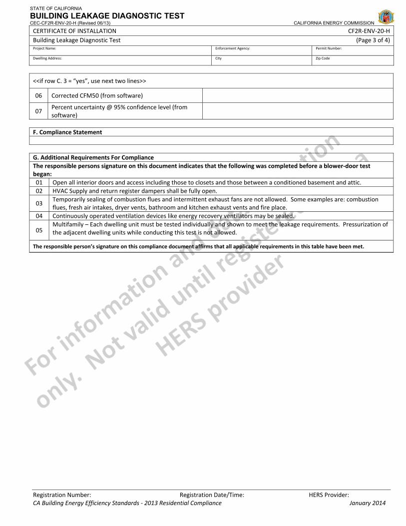
STATE OF CALIFORNIA
BUILDING LEAKAGE DIAGNOSTIC TEST CEC-CF2R-ENV-20-H (Revised 06/13) CALIFORNIA ENERGY COMMISSION
CERTIFICATE OF INSTALLATION CF2R‐ENV‐20‐H Building Leakage Diagnostic Test (Page 3 of 4) Project Name: Enforcement Agency: Permit Number:
Dwelling Address: City Zip Code
Registration Number: Registration Date/Time: HERS Provider: CA Building Energy Efficiency Standards ‐ 2013 Residential Compliance January 2014
<<if row C. 3 = “yes”, use next two lines>>
06 Corrected CFM50 (from software)
07 Percent uncertainty @ 95% confidence level (fromsoftware)
F. Compliance Statement G. Additional Requirements For Compliance The responsible persons signature on this document indicates that the following was completed before a blower‐door test began: 01 Open all interior doors and access including those to closets and those between a conditioned basement and attic.02 HVAC Supply and return register dampers shall be fully open.
03 Temporarily sealing of combustion flues and intermittent exhaust fans are not allowed. Some examples are: combustion flues, fresh air intakes, dryer vents, bathroom and kitchen exhaust vents and fire place.
04 Continuously operated ventilation devices like energy recovery ventilators may be sealed.
05 Multifamily – Each dwelling unit must be tested individually and shown to meet the leakage requirements. Pressurization of the adjacent dwelling units while conducting this test is not allowed.
The responsible person’s signature on this compliance document affirms that all applicable requirements in this table have been met.

STATE OF CALIFORNIA
BUILDING LEAKAGE DIAGNOSTIC TEST CEC-CF2R-ENV-20-H (Revised 06/13) CALIFORNIA ENERGY COMMISSION
CERTIFICATE OF INSTALLATION CF2R‐ENV‐20‐H Building Leakage Diagnostic Test (Page 4 of 4) Project Name: Enforcement Agency: Permit Number:
Dwelling Address: City Zip Code
Registration Number: Registration Date/Time: HERS Provider: CA Building Energy Efficiency Standards ‐ 2013 Residential Compliance January 2014
DOCUMENTATION AUTHOR'S DECLARATION STATEMENT1. I certify that this Certificate of Installation documentation is accurate and complete.
Documentation Author Name: Documentation Author Signature:
Documentation Author Company Name: Date Signed:
Address: CEA/HERS Certification Identification (If applicable):
City/State/Zip: Phone:
RESPONSIBLE PERSON'S DECLARATION STATEMENT
I certify the following under penalty of perjury, under the laws of the State of California:
1. The information provided on this Certificate of Installation is true and correct.
2. I am eligible under Division 3 of the Business and Professions Code in the applicable classification to accept responsibility for the system design, construction, or installation of features, materials, components, or manufactured devices for the scope of work identified on this Certificate of Installation and attest to the declarations in this statement (responsible builder/installer), otherwise I am an authorized representative of the responsible builder/installer.
3. The constructed or installed features, materials, components or manufactured devices (the installation) identified on this Certificate of Installation conforms to all applicable codes and regulations, and the installation conforms to the requirements given on the plans and specifications approved by the enforcement agency.
4. I understand that a HERS rater will check the installation to verify compliance, and that if such checking identifies defects; I am required to take corrective action at my expense. I understand that Energy Commission and HERS Provider representatives will also perform quality assurance checking of installations, including those approved as part of a sample group but not checked by a HERS rater, and if those installations fail to meet the requirements of such quality assurance checking, the required corrective action and additional checking/testing of other installations in that HERS sample group will be performed at my expense.
5. I reviewed a copy of the Certificate of Compliance approved by the enforcement agency that identifies the specific requirements for the scope of construction or installation identified on this Certificate of Installation, and I have ensured that the requirements that apply to the construction or installation have been met.
6. I will ensure that a registered copy of this Certificate of Installation shall be posted, or made available with the building permit(s) issued for the building, and made available to the enforcement agency for all applicable inspections. I understand that a registered copy of this Certificate of Installation is required to be included with the documentation the builder provides to the building owner at occupancy.
Responsible Builder/Installer Name: Responsible Builder/Installer Signature:
Company Name: (Installing Subcontractor or General Contractor or Builder/Owner) Position With Company (Title):
Address: CSLB License:
City/State/Zip: Phone Date Signed:
Third Party Quality Control Program (TPQCP) Status: Name of TPQCP (if applicable):

CERTIFICATE OF INSTALLATION – USER INSTRUCTIONS CF2R‐ENV‐20‐H Building Leakage Diagnostic Test – ENV‐20e (Page 1 of 3)
CA Building Energy Efficiency Standards ‐ 2013 Residential Compliance January 2014
Instructions for ENV20e Section A. Building Air Leakage – General Information
1. Select the appropriate test procedure. This selection will determine which version of this document will be used (a, b, c, d, or e) and therefore which data must be collected. Note that single‐point tests can only be used under certain conditions. Note that newer manometers have automatic functions for compensating for baseline (automatic baseline) and compensating for house pressures other than the target (@50 Pa). It is preferable to use these, when available, however if these automatic functions are to be used, they must BOTH be used.
2. This number is automatically pulled from the performance approach Certificate of Compliance and is the target maximum that was entered by the documentation author. If this number cannot be achieved, the performance compliance calculations can be redone with a higher number or without the requirement for building air leakage.
3. Enter the indoor temperature measured at the time that the building air leakage test was performed. 4. Enter the outdoor temperature measured at the time that the building air leakage test was performed. 5. Provide a brief description of the location where the blower door was installed for the test. Examples: “front entry door on
west side of house”, “door between house and garage”, “large window in family room”. 6. Enter the building elevation use the value for the closest city found in Joint Appendix JA2.2. Only elevations higher than
5000 feet require an adjustment to the calculations. 7. This number is automatically pulled from the performance approach Certificate of Compliance. It is used to calculate air
changes. 8. Enter the date that the building leakage test data was collected.
Section B. Diagnostic Equipment Information
1. Enter the number of blower door fan systems required to run simultaneously to pressurize the home for the building air leakage test. If more than one system is used, the fan flow numbers need to be manually added together, unless blower door software is used that will accommodate multiple fan systems running simultaneously.
2. Enter the appropriate information for each fan system used in the following rows. 3. Enter the make (brand) of the manometer used to collect the building air leakage data. Examples: Retrotec, Energy
Conservatory. 4. Enter the model of the manometer used to collect the building air leakage data. Examples: DM‐2 Mark II, DG700. 5. Enter the serial number of the manometer used to collect the building air leakage data. 6. Enter the most recent date that the manometer was calibrated by following manufacturer’s calibration specifications. 7. This field is automatically filled. If the calibration date was more than 12 months prior to the test date entered in Row A.8,
above, an error will appear. 8. Enter the make (brand) of the fan used to collect the building air leakage data. Examples: Retrotec, Energy Conservatory. 9. Enter the model of the fan used to collect the building air leakage data. Examples: US1000, Q46, BD3, BD4. 10. Enter the serial number of the fan used to collect the building air leakage data.
Section C. Envelope Leakage Test (specific to the ENV20e)
1. Enter the time average period used on the manometer during the test. Must be at least 10 seconds. 2. Enter the pre‐test baseline building pressure reading. 3. If ASTM E779‐10 compliant software is being used for the calculations, enter the name and version here. Otherwise,
choose “none”. 4. These are the numbered columns for the data points required for the test. There is a minimum of five and a maximum of
nine data points required for this test. 5. This shows which data points are required or optional for this test. There is a minimum of five and a maximum of nine data
points required for this test. 6. Enter the fan configuration (rings) that was used during the data acquisition. Examples: Ring A, Ring A1, Ring B2 7. Enter the induced building pressure from the manometer (automatic baseline feature turned on). It should be close to 50
Pa, but no less than 15 Pa. 8. Enter the Nominal CFM50 from the manometer (@50 Pa feature turned on). 9. This field is automatically calculated when using the online form. The equation used to calculate this value in the field equals (C.81+C.82+
C.83+ C.84+ C.85+C.86+ C.87+ C.88+ C.89)/N or the number of tests = Average Nominal CFM50 Section D. Altitude and Temperature Correction
1. This field is automatically calculated when using the online form. The equation used to calculate this value in the field equals:
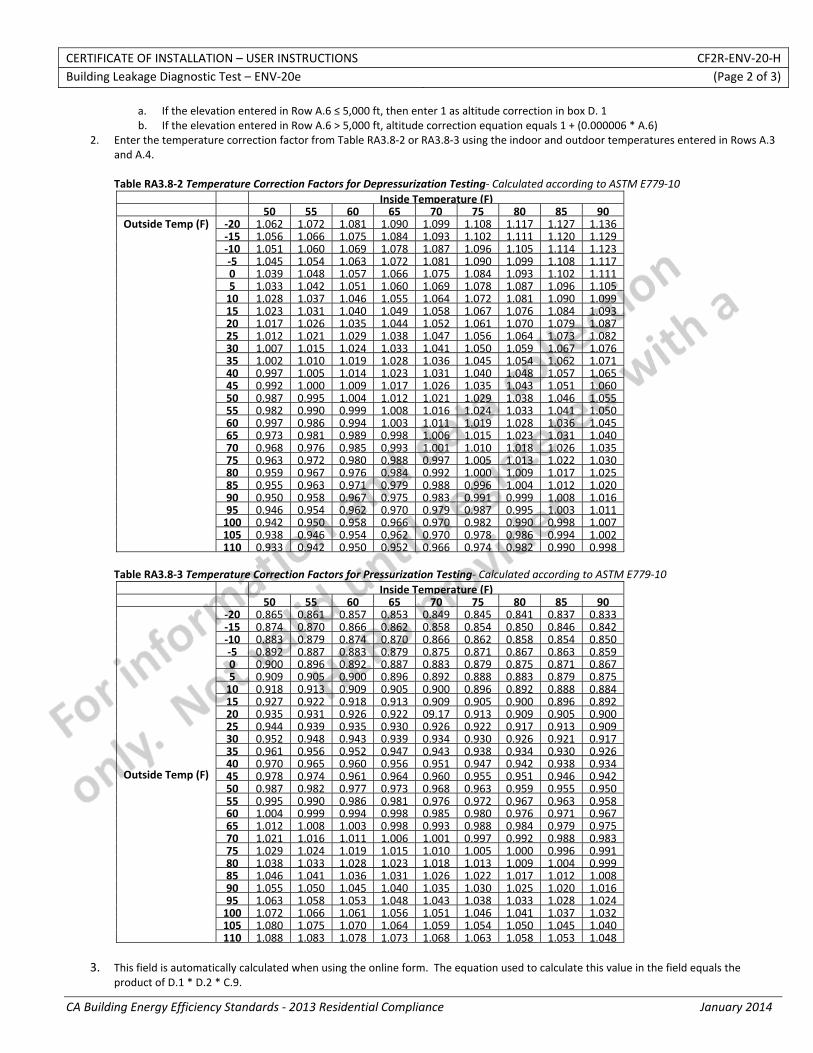
CERTIFICATE OF INSTALLATION – USER INSTRUCTIONS CF2R‐ENV‐20‐H Building Leakage Diagnostic Test – ENV‐20e (Page 2 of 3)
CA Building Energy Efficiency Standards ‐ 2013 Residential Compliance January 2014
a. If the elevation entered in Row A.6 ≤ 5,000 ft, then enter 1 as altitude correction in box D. 1 b. If the elevation entered in Row A.6 > 5,000 ft, altitude correction equation equals 1 + (0.000006 * A.6)
2. Enter the temperature correction factor from Table RA3.8‐2 or RA3.8‐3 using the indoor and outdoor temperatures entered in Rows A.3 and A.4. Table RA3.8‐2 Temperature Correction Factors for Depressurization Testing‐ Calculated according to ASTM E779‐10
Inside Temperature (F) 50 55 60 65 70 75 80 85 90
Outside Temp (F) ‐20 1.062 1.072 1.081 1.090 1.099 1.108 1.117 1.127 1.136 ‐15 1.056 1.066 1.075 1.084 1.093 1.102 1.111 1.120 1.129 ‐10 1.051 1.060 1.069 1.078 1.087 1.096 1.105 1.114 1.123 ‐5 1.045 1.054 1.063 1.072 1.081 1.090 1.099 1.108 1.117 0 1.039 1.048 1.057 1.066 1.075 1.084 1.093 1.102 1.111 5 1.033 1.042 1.051 1.060 1.069 1.078 1.087 1.096 1.105 10 1.028 1.037 1.046 1.055 1.064 1.072 1.081 1.090 1.099 15 1.023 1.031 1.040 1.049 1.058 1.067 1.076 1.084 1.093 20 1.017 1.026 1.035 1.044 1.052 1.061 1.070 1.079 1.087 25 1.012 1.021 1.029 1.038 1.047 1.056 1.064 1.073 1.082 30 1.007 1.015 1.024 1.033 1.041 1.050 1.059 1.067 1.076 35 1.002 1.010 1.019 1.028 1.036 1.045 1.054 1.062 1.071 40 0.997 1.005 1.014 1.023 1.031 1.040 1.048 1.057 1.065 45 0.992 1.000 1.009 1.017 1.026 1.035 1.043 1.051 1.060 50 0.987 0.995 1.004 1.012 1.021 1.029 1.038 1.046 1.055 55 0.982 0.990 0.999 1.008 1.016 1.024 1.033 1.041 1.050 60 0.997 0.986 0.994 1.003 1.011 1.019 1.028 1.036 1.045 65 0.973 0.981 0.989 0.998 1.006 1.015 1.023 1.031 1.040 70 0.968 0.976 0.985 0.993 1.001 1.010 1.018 1.026 1.035 75 0.963 0.972 0.980 0.988 0.997 1.005 1.013 1.022 1.030 80 0.959 0.967 0.976 0.984 0.992 1.000 1.009 1.017 1.025 85 0.955 0.963 0.971 0.979 0.988 0.996 1.004 1.012 1.020 90 0.950 0.958 0.967 0.975 0.983 0.991 0.999 1.008 1.016 95 0.946 0.954 0.962 0.970 0.979 0.987 0.995 1.003 1.011 100 0.942 0.950 0.958 0.966 0.970 0.982 0.990 0.998 1.007 105 0.938 0.946 0.954 0.962 0.970 0.978 0.986 0.994 1.002 110 0.933 0.942 0.950 0.952 0.966 0.974 0.982 0.990 0.998
Table RA3.8‐3 Temperature Correction Factors for Pressurization Testing‐ Calculated according to ASTM E779‐10
Inside Temperature (F) 50 55 60 65 70 75 80 85 90
Outside Temp (F)
‐20 0.865 0.861 0.857 0.853 0.849 0.845 0.841 0.837 0.833 ‐15 0.874 0.870 0.866 0.862 0.858 0.854 0.850 0.846 0.842 ‐10 0.883 0.879 0.874 0.870 0.866 0.862 0.858 0.854 0.850 ‐5 0.892 0.887 0.883 0.879 0.875 0.871 0.867 0.863 0.859 0 0.900 0.896 0.892 0.887 0.883 0.879 0.875 0.871 0.867 5 0.909 0.905 0.900 0.896 0.892 0.888 0.883 0.879 0.875 10 0.918 0.913 0.909 0.905 0.900 0.896 0.892 0.888 0.884 15 0.927 0.922 0.918 0.913 0.909 0.905 0.900 0.896 0.892 20 0.935 0.931 0.926 0.922 09.17 0.913 0.909 0.905 0.900 25 0.944 0.939 0.935 0.930 0.926 0.922 0.917 0.913 0.909 30 0.952 0.948 0.943 0.939 0.934 0.930 0.926 0.921 0.917 35 0.961 0.956 0.952 0.947 0.943 0.938 0.934 0.930 0.926 40 0.970 0.965 0.960 0.956 0.951 0.947 0.942 0.938 0.934 45 0.978 0.974 0.961 0.964 0.960 0.955 0.951 0.946 0.942 50 0.987 0.982 0.977 0.973 0.968 0.963 0.959 0.955 0.950 55 0.995 0.990 0.986 0.981 0.976 0.972 0.967 0.963 0.958 60 1.004 0.999 0.994 0.998 0.985 0.980 0.976 0.971 0.967 65 1.012 1.008 1.003 0.998 0.993 0.988 0.984 0.979 0.975 70 1.021 1.016 1.011 1.006 1.001 0.997 0.992 0.988 0.983 75 1.029 1.024 1.019 1.015 1.010 1.005 1.000 0.996 0.991 80 1.038 1.033 1.028 1.023 1.018 1.013 1.009 1.004 0.999 85 1.046 1.041 1.036 1.031 1.026 1.022 1.017 1.012 1.008 90 1.055 1.050 1.045 1.040 1.035 1.030 1.025 1.020 1.016 95 1.063 1.058 1.053 1.048 1.043 1.038 1.033 1.028 1.024 100 1.072 1.066 1.061 1.056 1.051 1.046 1.041 1.037 1.032 105 1.080 1.075 1.070 1.064 1.059 1.054 1.050 1.045 1.040 110 1.088 1.083 1.078 1.073 1.068 1.063 1.058 1.053 1.048
3. This field is automatically calculated when using the online form. The equation used to calculate this value in the field equals the
product of D.1 * D.2 * C.9.
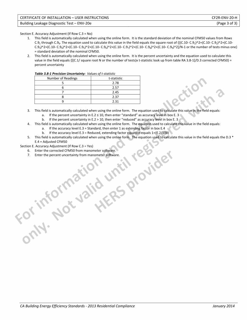
CERTIFICATE OF INSTALLATION – USER INSTRUCTIONS CF2R‐ENV‐20‐H Building Leakage Diagnostic Test – ENV‐20e (Page 3 of 3)
CA Building Energy Efficiency Standards ‐ 2013 Residential Compliance January 2014
Section E. Accuracy Adjustment (If Row C.3 = No) 1. This field is automatically calculated when using the online form. It is the standard deviation of the nominal CFM50 values from Rows
C.91 through C.99. The equation used to calculate this value in the field equals the square root of {[(C.10‐ C.91)^2+(C.10‐ C.92)^2+(C.10‐ C.93)^2+(C.10‐ C.94)^2+(C.10‐ C.95)^2+(C.10‐ C.96)^2+(C.10‐ C.97)^2+(C.10‐ C.98)^2+(C.10‐ C.99)^2]/N‐1 or the number of tests minus one} = standard deviation of the nominal CFM50.
2. This field is automatically calculated when using the online form. It is the percent uncertainty and the equation used to calculate this value in the field equals {[(C.1/ square root N or the number of tests)x t‐statistic look up from table RA 3.8‐1]/D.3 corrected CFM50} = percent uncertainty Table 3.8‐1 Precision Uncertainty: Values of t‐statistic
Number of Readings t‐statistic 5 2.78 6 2.57 7 2.45 8 2.37 9 2.31
3. This field is automatically calculated when using the online form. The equation used to calculate this value in the field equals:
a. If the percent uncertainty in E.2 ≤ 10, then enter “standard” as accuracy level in box E. 3 b. If the percent uncertainty in E.2 > 10, then enter “reduced” as accuracy level in box E. 3
4. This field is automatically calculated when using the online form. The equation used to calculate this value in the field equals: a. If the accuracy level E.3 = Standard, then enter 1 as extending factor in box E.4 b. If the accuracy level E.3 = Reduced, extending factor equation equals 1+(E.2/100)
5. This field is automatically calculated when using the online form. The equation used to calculate this value in the field equals the D.3 * E.4 = Adjusted CFM50
Section E. Accuracy Adjustment (If Row C.3 = Yes) 6. Enter the corrected CFM50 from manometer software. 7. Enter the percent uncertainty from manometer software.
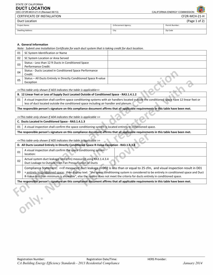
STATE OF CALIFORNIA
DUCT LOCATION CEC-CF2R-MCH-21-H (Revised 06/13) CALIFORNIA ENERGY COMMISSION
CERTIFICATE OF INSTALLATION CF2R‐MCH‐21‐H Duct Location (Page 1 of 2) Project Name: Enforcement Agency: Permit Number:
Dwelling Address: City Zip Code
Registration Number: Registration Date/Time: HERS Provider: CA Building Energy Efficiency Standards - 2013 Residential Compliance January 2014
A. General Information Note: Submit one Installation Certificate for each duct system that is taking credit for duct location.
01 SC System Identification or Name
02 SC System Location or Area Served
03 Status ‐ Less than 12 ft Ducts in Conditioned Space Performance Credit:
04 Status ‐ Ducts Located In Conditioned Space Performance Credit:
05 Status – All Ducts Entirely in Directly Conditioned Space R‐value Exception
<<This table only shown if A03 indicates the table is applicable>>
B. 12 Linear Feet or Less of Supply Duct Located Outside of Conditioned Space ‐ RA3.1.4.1.2
01 A visual inspection shall confirm space conditioning systems with air handlers located outside the conditioned space have 12 linear feet or less of duct located outside the conditioned space including air handler and plenum.
The responsible person’s signature on this compliance document affirms that all applicable requirements in this table have been met.
<<This table only shown if A04 indicates the table is applicable >>
C. Ducts Located In Conditioned Space ‐ RA3.1.4.1.3
01 A visual inspection shall confirm the space conditioning system is located entirely in conditioned space.
The responsible person’s signature on this compliance document affirms that all applicable requirements in this table have been met.
<<This table only shown if A05 indicates the table is applicable >>
D. All Ducts Located Entirely in Directly Conditioned Space R‐Value Exception ‐ RA3.1.4.3.8
01 A visual inspection shall confirm the space conditioning system location:
02 Actual system duct leakage rate (cfm) measured using RA3.1.4.3.4 Duct Leakage to Outside from Fan Pressurization of Ducts
03 Compliance Statement: <<if measured duct leakage in D02 is less than or equal to 25 cfm, and visual inspection result in D01 = entirely in conditioned space; then display text: "the space conditioning system is considered to be entirely in conditioned space and Duct R‐Value less than minimum is allowable", else the system does not meet the criteria for ducts entirely in conditioned space.
The responsible person’s signature on this compliance document affirms that all applicable requirements in this table have been met.
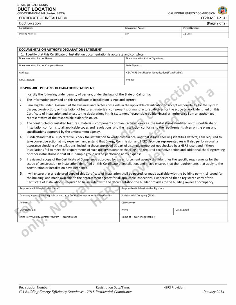
STATE OF CALIFORNIA
DUCT LOCATION CEC-CF2R-MCH-21-H (Revised 06/13) CALIFORNIA ENERGY COMMISSION
CERTIFICATE OF INSTALLATION CF2R‐MCH‐21‐H Duct Location (Page 2 of 2) Project Name: Enforcement Agency: Permit Number:
Dwelling Address: City Zip Code
Registration Number: Registration Date/Time: HERS Provider: CA Building Energy Efficiency Standards - 2013 Residential Compliance January 2014
DOCUMENTATION AUTHOR'S DECLARATION STATEMENT1. I certify that this Certificate of Installation documentation is accurate and complete.
Documentation Author Name: Documentation Author Signature:
Documentation Author Company Name: Date Signed:
Address: CEA/HERS Certification Identification (If applicable):
City/State/Zip: Phone:
RESPONSIBLE PERSON'S DECLARATION STATEMENT
I certify the following under penalty of perjury, under the laws of the State of California:
1. The information provided on this Certificate of Installation is true and correct.
2. I am eligible under Division 3 of the Business and Professions Code in the applicable classification to accept responsibility for the system design, construction, or installation of features, materials, components, or manufactured devices for the scope of work identified on this Certificate of Installation and attest to the declarations in this statement (responsible builder/installer), otherwise I am an authorized representative of the responsible builder/installer.
3. The constructed or installed features, materials, components or manufactured devices (the installation) identified on this Certificate of Installation conforms to all applicable codes and regulations, and the installation conforms to the requirements given on the plans and specifications approved by the enforcement agency.
4. I understand that a HERS rater will check the installation to verify compliance, and that if such checking identifies defects; I am required to take corrective action at my expense. I understand that Energy Commission and HERS Provider representatives will also perform quality assurance checking of installations, including those approved as part of a sample group but not checked by a HERS rater, and if those installations fail to meet the requirements of such quality assurance checking, the required corrective action and additional checking/testing of other installations in that HERS sample group will be performed at my expense.
5. I reviewed a copy of the Certificate of Compliance approved by the enforcement agency that identifies the specific requirements for the scope of construction or installation identified on this Certificate of Installation, and I have ensured that the requirements that apply to the construction or installation have been met.
6. I will ensure that a registered copy of this Certificate of Installation shall be posted, or made available with the building permit(s) issued for the building, and made available to the enforcement agency for all applicable inspections. I understand that a registered copy of this Certificate of Installation is required to be included with the documentation the builder provides to the building owner at occupancy.
Responsible Builder/Installer Name: Responsible Builder/Installer Signature:
Company Name: (Installing Subcontractor or General Contractor or Builder/Owner) Position With Company (Title):
Address: CSLB License:
City/State/Zip: Phone Date Signed:
Third Party Quality Control Program (TPQCP) Status: Name of TPQCP (if applicable):
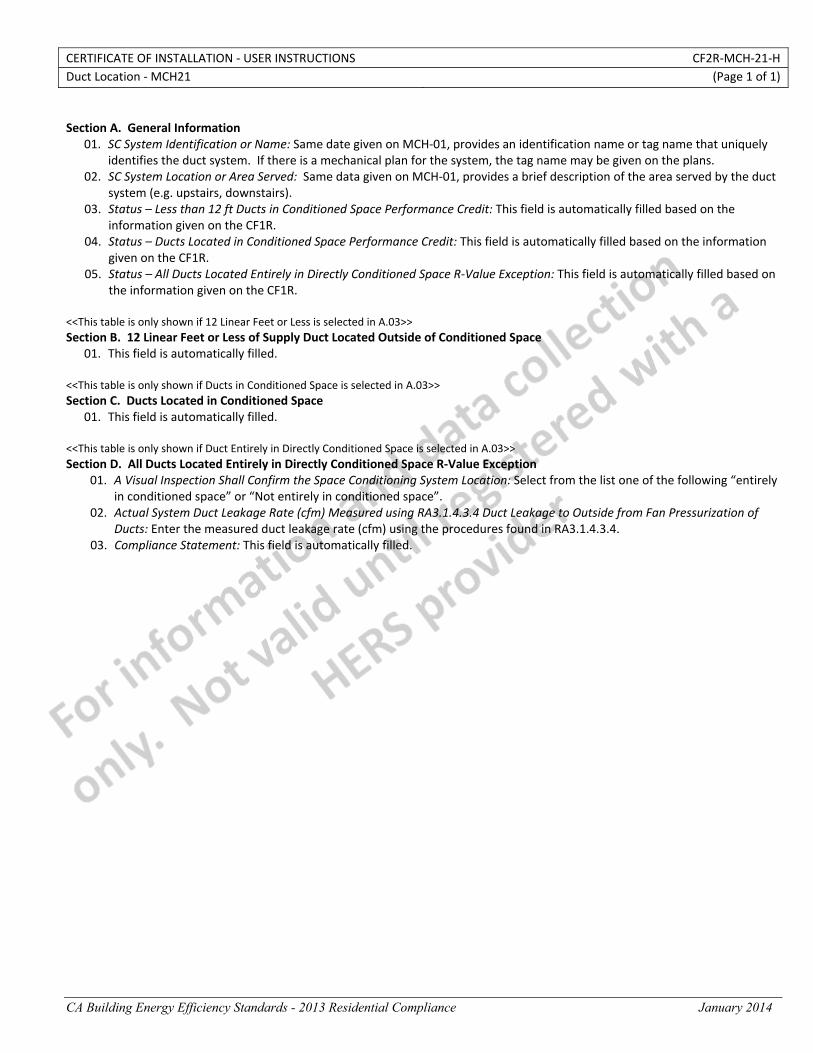
CERTIFICATE OF INSTALLATION ‐ USER INSTRUCTIONS CF2R‐MCH‐21‐H Duct Location ‐ MCH21 (Page 1 of 1)
CA Building Energy Efficiency Standards - 2013 Residential Compliance January 2014
Section A. General Information
01. SC System Identification or Name: Same date given on MCH‐01, provides an identification name or tag name that uniquely identifies the duct system. If there is a mechanical plan for the system, the tag name may be given on the plans.
02. SC System Location or Area Served: Same data given on MCH‐01, provides a brief description of the area served by the duct system (e.g. upstairs, downstairs).
03. Status – Less than 12 ft Ducts in Conditioned Space Performance Credit: This field is automatically filled based on the information given on the CF1R.
04. Status – Ducts Located in Conditioned Space Performance Credit: This field is automatically filled based on the information given on the CF1R.
05. Status – All Ducts Located Entirely in Directly Conditioned Space R‐Value Exception: This field is automatically filled based on the information given on the CF1R.
<<This table is only shown if 12 Linear Feet or Less is selected in A.03>> Section B. 12 Linear Feet or Less of Supply Duct Located Outside of Conditioned Space
01. This field is automatically filled. <<This table is only shown if Ducts in Conditioned Space is selected in A.03>> Section C. Ducts Located in Conditioned Space
01. This field is automatically filled. <<This table is only shown if Duct Entirely in Directly Conditioned Space is selected in A.03>> Section D. All Ducts Located Entirely in Directly Conditioned Space R‐Value Exception
01. A Visual Inspection Shall Confirm the Space Conditioning System Location: Select from the list one of the following “entirely in conditioned space” or “Not entirely in conditioned space”.
02. Actual System Duct Leakage Rate (cfm) Measured using RA3.1.4.3.4 Duct Leakage to Outside from Fan Pressurization of Ducts: Enter the measured duct leakage rate (cfm) using the procedures found in RA3.1.4.3.4.
03. Compliance Statement: This field is automatically filled.
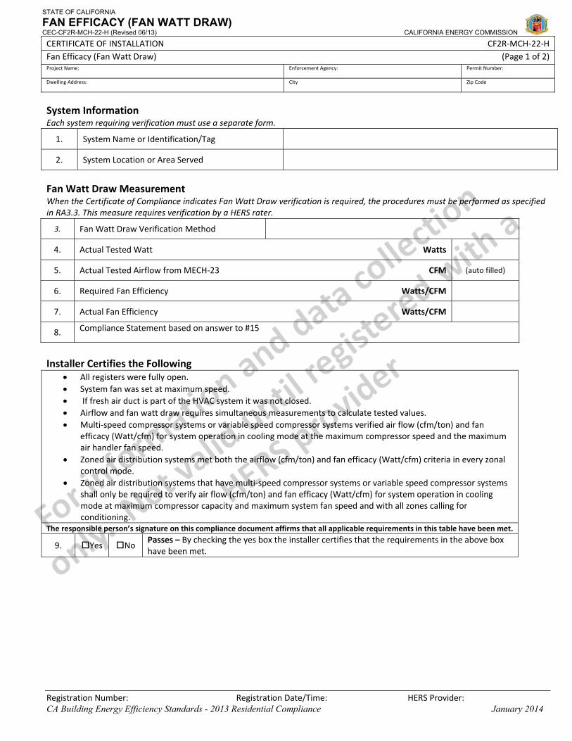
STATE OF CALIFORNIA
FAN EFFICACY (FAN WATT DRAW) CEC-CF2R-MCH-22-H (Revised 06/13) CALIFORNIA ENERGY COMMISSION
CERTIFICATE OF INSTALLATION CF2R‐MCH‐22‐H Fan Efficacy (Fan Watt Draw) (Page 1 of 2) Project Name: Enforcement Agency: Permit Number:
Dwelling Address: City Zip Code
Registration Number: Registration Date/Time: HERS Provider: CA Building Energy Efficiency Standards - 2013 Residential Compliance January 2014
System Information Each system requiring verification must use a separate form.
1. System Name or Identification/Tag
2. System Location or Area Served
Fan Watt Draw Measurement When the Certificate of Compliance indicates Fan Watt Draw verification is required, the procedures must be performed as specified in RA3.3. This measure requires verification by a HERS rater.
3. Fan Watt Draw Verification Method
4. Actual Tested Watt Watts
5. Actual Tested Airflow from MECH‐23 CFM (auto filled)
6. Required Fan Efficiency Watts/CFM
7. Actual Fan Efficiency Watts/CFM
8. Compliance Statement based on answer to #15
Installer Certifies the Following
• All registers were fully open. • System fan was set at maximum speed. • If fresh air duct is part of the HVAC system it was not closed. • Airflow and fan watt draw requires simultaneous measurements to calculate tested values. • Multi‐speed compressor systems or variable speed compressor systems verified air flow (cfm/ton) and fan
efficacy (Watt/cfm) for system operation in cooling mode at the maximum compressor speed and the maximum air handler fan speed.
• Zoned air distribution systems met both the airflow (cfm/ton) and fan efficacy (Watt/cfm) criteria in every zonal control mode.
• Zoned air distribution systems that have multi‐speed compressor systems or variable speed compressor systems shall only be required to verify air flow (cfm/ton) and fan efficacy (Watt/cfm) for system operation in cooling mode at maximum compressor capacity and maximum system fan speed and with all zones calling for conditioning.
The responsible person’s signature on this compliance document affirms that all applicable requirements in this table have been met.
9. Yes No Passes – By checking the yes box the installer certifies that the requirements in the above box have been met.
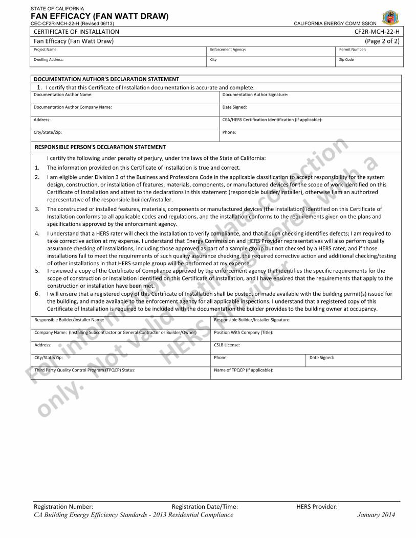
STATE OF CALIFORNIA
FAN EFFICACY (FAN WATT DRAW) CEC-CF2R-MCH-22-H (Revised 06/13) CALIFORNIA ENERGY COMMISSION
CERTIFICATE OF INSTALLATION CF2R‐MCH‐22‐H Fan Efficacy (Fan Watt Draw) (Page 2 of 2) Project Name: Enforcement Agency: Permit Number:
Dwelling Address: City Zip Code
Registration Number: Registration Date/Time: HERS Provider: CA Building Energy Efficiency Standards - 2013 Residential Compliance January 2014
DOCUMENTATION AUTHOR'S DECLARATION STATEMENT1. I certify that this Certificate of Installation documentation is accurate and complete.
Documentation Author Name: Documentation Author Signature:
Documentation Author Company Name: Date Signed:
Address: CEA/HERS Certification Identification (If applicable):
City/State/Zip: Phone:
RESPONSIBLE PERSON'S DECLARATION STATEMENT
I certify the following under penalty of perjury, under the laws of the State of California:
1. The information provided on this Certificate of Installation is true and correct.
2. I am eligible under Division 3 of the Business and Professions Code in the applicable classification to accept responsibility for the system design, construction, or installation of features, materials, components, or manufactured devices for the scope of work identified on this Certificate of Installation and attest to the declarations in this statement (responsible builder/installer), otherwise I am an authorized representative of the responsible builder/installer.
3. The constructed or installed features, materials, components or manufactured devices (the installation) identified on this Certificate of Installation conforms to all applicable codes and regulations, and the installation conforms to the requirements given on the plans and specifications approved by the enforcement agency.
4. I understand that a HERS rater will check the installation to verify compliance, and that if such checking identifies defects; I am required to take corrective action at my expense. I understand that Energy Commission and HERS Provider representatives will also perform quality assurance checking of installations, including those approved as part of a sample group but not checked by a HERS rater, and if those installations fail to meet the requirements of such quality assurance checking, the required corrective action and additional checking/testing of other installations in that HERS sample group will be performed at my expense.
5. I reviewed a copy of the Certificate of Compliance approved by the enforcement agency that identifies the specific requirements for the scope of construction or installation identified on this Certificate of Installation, and I have ensured that the requirements that apply to the construction or installation have been met.
6. I will ensure that a registered copy of this Certificate of Installation shall be posted, or made available with the building permit(s) issued for the building, and made available to the enforcement agency for all applicable inspections. I understand that a registered copy of this Certificate of Installation is required to be included with the documentation the builder provides to the building owner at occupancy.
Responsible Builder/Installer Name: Responsible Builder/Installer Signature:
Company Name: (Installing Subcontractor or General Contractor or Builder/Owner) Position With Company (Title):
Address: CSLB License:
City/State/Zip: Phone Date Signed:
Third Party Quality Control Program (TPQCP) Status: Name of TPQCP (if applicable):
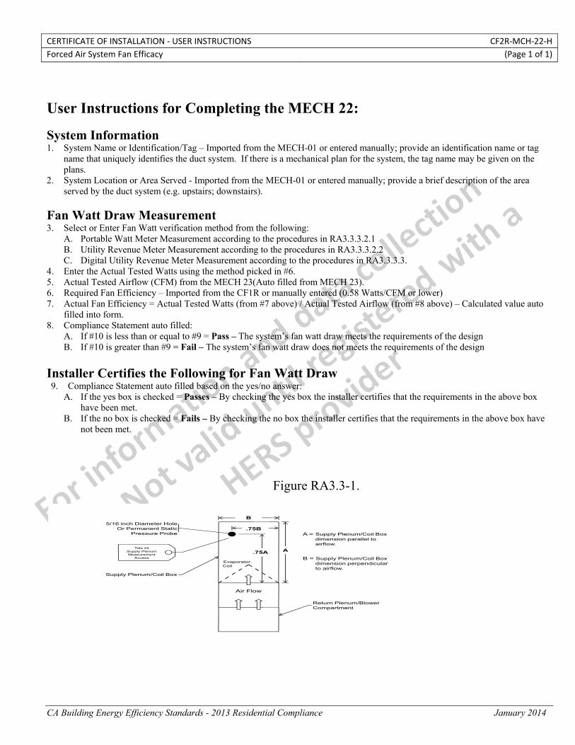
CERTIFICATE OF INSTALLATION ‐ USER INSTRUCTIONS CF2R‐MCH‐22‐H Forced Air System Fan Efficacy (Page 1 of 1)
CA Building Energy Efficiency Standards - 2013 Residential Compliance January 2014
User Instructions for Completing the MECH 22: System Information 1. System Name or Identification/Tag – Imported from the MECH-01 or entered manually; provide an identification name or tag
name that uniquely identifies the duct system. If there is a mechanical plan for the system, the tag name may be given on the plans.
2. System Location or Area Served - Imported from the MECH-01 or entered manually; provide a brief description of the area served by the duct system (e.g. upstairs; downstairs).
Fan Watt Draw Measurement 3. Select or Enter Fan Watt verification method from the following:
A. Portable Watt Meter Measurement according to the procedures in RA3.3.3.2.1 B. Utility Revenue Meter Measurement according to the procedures in RA3.3.3.2.2 C. Digital Utility Revenue Meter Measurement according to the procedures in RA3.3.3.3.
4. Enter the Actual Tested Watts using the method picked in #6. 5. Actual Tested Airflow (CFM) from the MECH 23(Auto filled from MECH 23). 6. Required Fan Efficiency – Imported from the CF1R or manually entered (0.58 Watts/CFM or lower) 7. Actual Fan Efficiency = Actual Tested Watts (from #7 above) / Actual Tested Airflow (from #8 above) – Calculated value auto
filled into form. 8. Compliance Statement auto filled:
A. If #10 is less than or equal to #9 = Pass – The system’s fan watt draw meets the requirements of the design B. If #10 is greater than #9 = Fail – The system’s fan watt draw does not meets the requirements of the design
Installer Certifies the Following for Fan Watt Draw 9. Compliance Statement auto filled based on the yes/no answer:
A. If the yes box is checked = Passes – By checking the yes box the installer certifies that the requirements in the above box have been met.
B. If the no box is checked = Fails – By checking the no box the installer certifies that the requirements in the above box have not been met.
Figure RA3.3-1.
B
A
Air Flow
Evaporator Coil
.75A
.75BA = Supply Plenum/Coil Box
dimension parallel to airflow.
B = Supply Plenum/Coil Box dimension perpendicular to airflow.
Return Plenum/Blower Compartment
Supply Plenum/Coil Box
Title 24 Supply Plenum Measurement
Access
5/16 inch Diameter HoleOr Permanent Static
Pressure Probe

STATE OF CALIFORNIA
SPACE CONDITIONING SYSTEM AIRFLOW RATE CEC-CF2R-MCH-23-H (Revised 06/13) CALIFORNIA ENERGY COMMISSION
CERTIFICATE OF INSTALLATION CF2R‐MCH‐23‐H Space Conditioning System Airflow Rate (Page 1 of 3) Project Name: Enforcement Agency: Permit Number:
Dwelling Address: City Zip Code
Registration Number: Registration Date/Time: HERS Provider: CA Building Energy Efficiency Standards ‐ 2013 Residential Compliance January 2014
A. Ducted Cooling System Information
01 System Identification or Name
02 System Location or Area Served
03 Nominal Cooling Capacity (tons) of Condenser
04 System Installation Type
05 Cooling System Zonal Control Type
06 Bypass Duct Status
07 Required Minimum System Airflow Rate (cfm)
08 Allowable Minimum Zonal Airflow Rate (cfm)
09 Date of System Airflow Rate Measurement
10 Type of System Airflow Rate Compliance
B. Hole for the placement of a Static Pressure Probe (HSPP), and Permanently installed Static Pressure Probe (PSPP) in the supply plenum. Procedures for installing HSPP or PSPP are specified in RA3.3.1.1.
01 Method used to demonstrate compliance with the HSPP/PSPP requirement
C. Airflow Rate Measurement Apparatus and Procedure InformationInstrument Specifications ae given in RA3.3.1.1, and system airflow rate measurement apparatus information is given in RA3.3.2.
01 Airflow Rate Measurement Type used for this airflow rate verification.
03 Manufacturer of Airflow Measurement Apparatus
04 Model number of Airflow Measurement Apparatus
05 Certification Status of the Airflow Measurement Apparatus Accuracy
06 determine compliance methodisplay applicable tables belo(this row not visible to user)
d for this document; w;
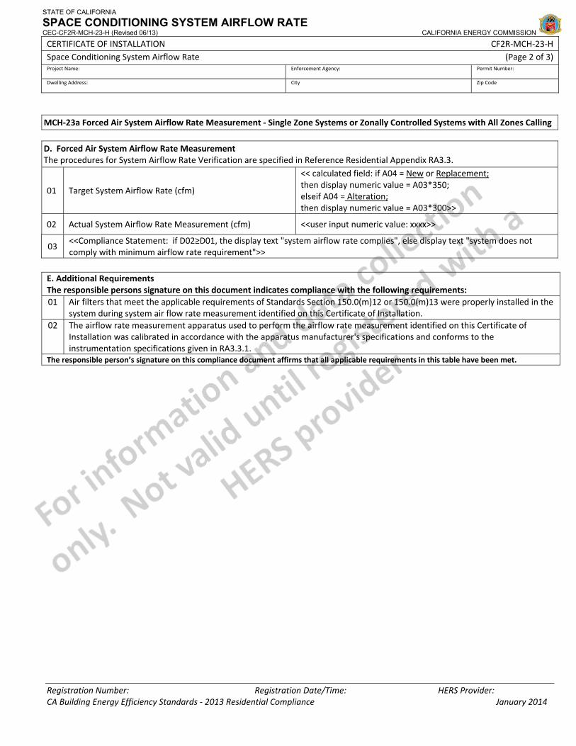
STATE OF CALIFORNIA
SPACE CONDITIONING SYSTEM AIRFLOW RATE CEC-CF2R-MCH-23-H (Revised 06/13) CALIFORNIA ENERGY COMMISSION
CERTIFICATE OF INSTALLATION CF2R‐MCH‐23‐H Space Conditioning System Airflow Rate (Page 2 of 3) Project Name: Enforcement Agency: Permit Number:
Dwelling Address: City Zip Code
Registration Number: Registration Date/Time: HERS Provider: CA Building Energy Efficiency Standards ‐ 2013 Residential Compliance January 2014
MCH‐23a Forced Air System Airflow Rate Measurement ‐ Single Zone Systems or Zonally Controlled Systems with All Zones Calling D. Forced Air System Airflow Rate MeasurementThe procedures for System Airflow Rate Verification are specified in Reference Residential Appendix RA3.3.
01 Target System Airflow Rate (cfm)
<< calculated field: if A04 = New or Replacement;then display numeric value = A03*350; elseif A04 = Alteration; then display numeric value = A03*300>>
02 Actual System Airflow Rate Measurement (cfm) <<user input numeric value: xxxx>>
03 <<Compliance Statement: if D02≥D01, the display text "system airflow rate complies", else display text "system does not comply with minimum airflow rate requirement">>
E. Additional Requirements The responsible persons signature on this document indicates compliance with the following requirements: 01 Air filters that meet the applicable requirements of Standards Section 150.0(m)12 or 150.0(m)13 were properly installed in the
system during system air flow rate measurement identified on this Certificate of Installation. 02 The airflow rate measurement apparatus used to perform the airflow rate measurement identified on this Certificate of
Installation was calibrated in accordance with the apparatus manufacturer's specifications and conforms to the instrumentation specifications given in RA3.3.1.
The responsible person’s signature on this compliance document affirms that all applicable requirements in this table have been met.

STATE OF CALIFORNIA
SPACE CONDITIONING SYSTEM AIRFLOW RATE CEC-CF2R-MCH-23-H (Revised 06/13) CALIFORNIA ENERGY COMMISSION
CERTIFICATE OF INSTALLATION CF2R‐MCH‐23‐H Space Conditioning System Airflow Rate (Page 3 of 3) Project Name: Enforcement Agency: Permit Number:
Dwelling Address: City Zip Code
Registration Number: Registration Date/Time: HERS Provider: CA Building Energy Efficiency Standards ‐ 2013 Residential Compliance January 2014
DOCUMENTATION AUTHOR'S DECLARATION STATEMENT1. I certify that this Certificate of Installation documentation is accurate and complete.
Documentation Author Name: Documentation Author Signature:
Documentation Author Company Name: Date Signed:
Address: CEA/HERS Certification Identification (If applicable):
City/State/Zip: Phone:
RESPONSIBLE PERSON'S DECLARATION STATEMENT
I certify the following under penalty of perjury, under the laws of the State of California:
1. The information provided on this Certificate of Installation is true and correct.
2. I am eligible under Division 3 of the Business and Professions Code in the applicable classification to accept responsibility for the system design, construction, or installation of features, materials, components, or manufactured devices for the scope of work identified on this Certificate of Installation and attest to the declarations in this statement (responsible builder/installer), otherwise I am an authorized representative of the responsible builder/installer.
3. The constructed or installed features, materials, components or manufactured devices (the installation) identified on this Certificate of Installation conforms to all applicable codes and regulations, and the installation conforms to the requirements given on the plans and specifications approved by the enforcement agency.
4. I understand that a HERS rater will check the installation to verify compliance, and that if such checking identifies defects; I am required to take corrective action at my expense. I understand that Energy Commission and HERS Provider representatives will also perform quality assurance checking of installations, including those approved as part of a sample group but not checked by a HERS rater, and if those installations fail to meet the requirements of such quality assurance checking, the required corrective action and additional checking/testing of other installations in that HERS sample group will be performed at my expense.
5. I reviewed a copy of the Certificate of Compliance approved by the enforcement agency that identifies the specific requirements for the scope of construction or installation identified on this Certificate of Installation, and I have ensured that the requirements that apply to the construction or installation have been met.
6. I will ensure that a registered copy of this Certificate of Installation shall be posted, or made available with the building permit(s) issued for the building, and made available to the enforcement agency for all applicable inspections. I understand that a registered copy of this Certificate of Installation is required to be included with the documentation the builder provides to the building owner at occupancy.
Responsible Builder/Installer Name: Responsible Builder/Installer Signature:
Company Name: (Installing Subcontractor or General Contractor or Builder/Owner) Position With Company (Title):
Address: CSLB License:
City/State/Zip: Phone Date Signed:
Third Party Quality Control Program (TPQCP) Status: Name of TPQCP (if applicable):
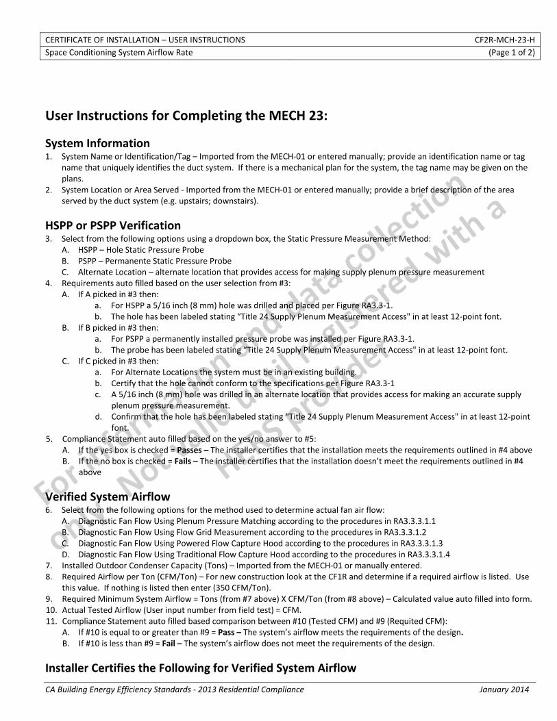
CERTIFICATE OF INSTALLATION – USER INSTRUCTIONS CF2R‐MCH‐23‐H Space Conditioning System Airflow Rate (Page 1 of 2)
CA Building Energy Efficiency Standards ‐ 2013 Residential Compliance January 2014
User Instructions for Completing the MECH 23:
System Information 1. System Name or Identification/Tag – Imported from the MECH‐01 or entered manually; provide an identification name or tag
name that uniquely identifies the duct system. If there is a mechanical plan for the system, the tag name may be given on the plans.
2. System Location or Area Served ‐ Imported from the MECH‐01 or entered manually; provide a brief description of the area served by the duct system (e.g. upstairs; downstairs).
HSPP or PSPP Verification 3. Select from the following options using a dropdown box, the Static Pressure Measurement Method:
A. HSPP – Hole Static Pressure Probe B. PSPP – Permanente Static Pressure Probe C. Alternate Location – alternate location that provides access for making supply plenum pressure measurement
4. Requirements auto filled based on the user selection from #3: A. If A picked in #3 then:
a. For HSPP a 5/16 inch (8 mm) hole was drilled and placed per Figure RA3.3‐1. b. The hole has been labeled stating “Title 24 Supply Plenum Measurement Access" in at least 12‐point font.
B. If B picked in #3 then: a. For PSPP a permanently installed pressure probe was installed per Figure RA3.3‐1. b. The probe has been labeled stating “Title 24 Supply Plenum Measurement Access" in at least 12‐point font.
C. If C picked in #3 then: a. For Alternate Locations the system must be in an existing building. b. Certify that the hole cannot conform to the specifications per Figure RA3.3‐1 c. A 5/16 inch (8 mm) hole was drilled in an alternate location that provides access for making an accurate supply
plenum pressure measurement. d. Confirm that the hole has been labeled stating “Title 24 Supply Plenum Measurement Access" in at least 12‐point
font. 5. Compliance Statement auto filled based on the yes/no answer to #5:
A. If the yes box is checked = Passes – The installer certifies that the installation meets the requirements outlined in #4 above B. If the no box is checked = Fails – The installer certifies that the installation doesn’t meet the requirements outlined in #4
above
Verified System Airflow 6. Select from the following options for the method used to determine actual fan air flow:
A. Diagnostic Fan Flow Using Plenum Pressure Matching according to the procedures in RA3.3.3.1.1 B. Diagnostic Fan Flow Using Flow Grid Measurement according to the procedures in RA3.3.3.1.2 C. Diagnostic Fan Flow Using Powered Flow Capture Hood according to the procedures in RA3.3.3.1.3 D. Diagnostic Fan Flow Using Traditional Flow Capture Hood according to the procedures in RA3.3.3.1.4
7. Installed Outdoor Condenser Capacity (Tons) – Imported from the MECH‐01 or manually entered. 8. Required Airflow per Ton (CFM/Ton) – For new construction look at the CF1R and determine if a required airflow is listed. Use
this value. If nothing is listed then enter (350 CFM/Ton). 9. Required Minimum System Airflow = Tons (from #7 above) X CFM/Ton (from #8 above) – Calculated value auto filled into form. 10. Actual Tested Airflow (User input number from field test) = CFM. 11. Compliance Statement auto filled based comparison between #10 (Tested CFM) and #9 (Requited CFM):
A. If #10 is equal to or greater than #9 = Pass – The system’s airflow meets the requirements of the design. B. If #10 is less than #9 = Fail – The system’s airflow does not meet the requirements of the design.
Installer Certifies the Following for Verified System Airflow

CERTIFICATE OF INSTALLATION – USER INSTRUCTIONS CF2R‐MCH‐23‐H Space Conditioning System Airflow Rate (Page 2 of 2)
CA Building Energy Efficiency Standards ‐ 2013 Residential Compliance January 2014
12. Compliance Statement auto filled based on the yes/no answer to #12: A. If the yes box is checked = Passes – By checking the yes box the installer certifies that the requirements in the above box
have been met. B. If the no box is checked = Fails – By checking the no box the installer certifies that the requirements in the above box have
not been met.
Figure RA3.3‐1.
B
A
Air Flow
Evaporator Coil
.75A
.75BA = Supply Plenum/Coil Box
dimension parallel to airflow.
B = Supply Plenum/Coil Box dimension perpendicular to airflow.
Return Plenum/Blower Compartment
Supply Plenum/Coil Box
Title 24 Supply Plenum Measurement
Access
5/16 inch Diameter HoleOr Permanent Static
Pressure Probe
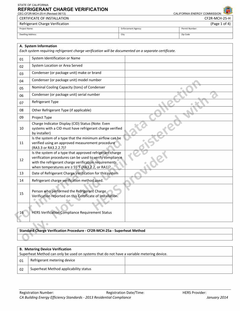
STATE OF CALIFORNIA
REFRIGERANT CHARGE VERIFICATION CEC-CF2R-MCH-25-H (Revised 06/13) CALIFORNIA ENERGY COMMISSION
CERTIFICATE OF INSTALLATION CF2R‐MCH‐25‐H Refrigerant Charge Verification (Page 1 of 4) Project Name: Enforcement Agency: Permit Number:
Dwelling Address: City Zip Code
Registration Number: Registration Date/Time: HERS Provider: CA Building Energy Efficiency Standards ‐ 2013 Residential Compliance January 2014
A. System Information Each system requiring refrigerant charge verification will be documented on a separate certificate.
01 System Identification or Name
02 System Location or Area Served
03 Condenser (or package unit) make or brand
04 Condenser (or package unit) model number
05 Nominal Cooling Capacity (tons) of Condenser
06 Condenser (or package unit) serial number
07 Refrigerant Type
08 Other Refrigerant Type (if applicable)
09 Project Type
10 Charge Indicator Display (CID) Status (Note: Even systems with a CID must have refrigerant charge verified by installer)
11 Is the system of a type that the minimum airflow can be verified using an approved measurement procedure (RA3.3 or RA3.2.2.7)?
12
Is the system of a type that approved refrigerant charge verification procedures can be used to verify compliance with the refrigerant charge verification requirements when temperatures are ≥ 55°F (RA3.2.2, or RA1)?
13 Date of Refrigerant Charge Verification for this system
14 Refrigerant charge verification method used.
15 Person who performed the Refrigerant Charge Verification reported on this Certificate of Installation:
16 HERS Verification Compliance Requirement Status
Standard Charge Verification Procedure ‐ CF2R‐MCH‐25a ‐ Superheat Method
B. Metering Device Verification Superheat Method can only be used on systems that do not have a variable metering device.
01 Refrigerant metering device
02 Superheat Method applicability status
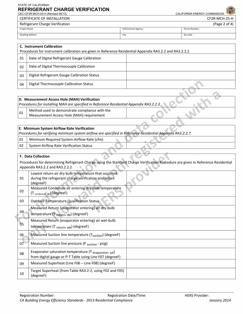
STATE OF CALIFORNIA
REFRIGERANT CHARGE VERIFICATION CEC-CF2R-MCH-25-H (Revised 06/13) CALIFORNIA ENERGY COMMISSION
CERTIFICATE OF INSTALLATION CF2R‐MCH‐25‐H Refrigerant Charge Verification (Page 2 of 4) Project Name: Enforcement Agency: Permit Number:
Dwelling Address: City Zip Code
Registration Number: Registration Date/Time: HERS Provider: CA Building Energy Efficiency Standards ‐ 2013 Residential Compliance January 2014
C. Instrument Calibration Procedures for instrument calibration are given in Reference Residential Appendix RA3.2.2 and RA3.2.2.2
01 Date of Digital Refrigerant Gauge Calibration
02 Date of Digital Thermocouple Calibration
03 Digital Refrigerant Gauge Calibration Status
04 Digital Thermocouple Calibration Status
D. Measurement Access Hole (MAH) VerificationProcedures for installing MAH are specified in Reference Residential Appendix RA3.2.2.3
01 Method used to demonstrate compliance with the Measurement Access Hole (MAH) requirement
E. Minimum System Airflow Rate Verification Procedures for verifying minimum system airflow are specified in Reference Residential Appendix RA3.2.2.7.
01 Minimum Required System Airflow Rate (cfm)
02 System Airflow Rate Verification Status F. Data Collection
Procedures for determining Refrigerant Charge using the Standard Charge Verification Procedure are given in Reference Residential Appendix RA3.2.2 and RA3.2.2.2
01 Lowest return air dry bulb temperature that occurred during the refrigerant charge verification procedure (degreeF)
02 Measured Condenser air entering dry‐bulb temperature (T condenser, db) (degreeF)
03 Outdoor Temperature Qualification Status
04 Measured Return (evaporator entering) air dry‐bulb
temperature (T return, db) (degreeF)
05 Measured Return (evaporator entering) air wet‐bulb
temperature (T return, wb) (degreeF)
06 Measured Suction line temperature (Tsuction) (degreeF)
07 Measured Suction line pressure (P suction ‐ psig)
08 Evaporator saturation temperature (T evaporator, sat) from digital gauge or P‐T Table using Line F07 (degreeF)
09 Measured Superheat (Line F06 – Line F08) (degreeF)
10 Target Superheat (from Table RA3.2‐2, using F02 and F05) (degreeF)
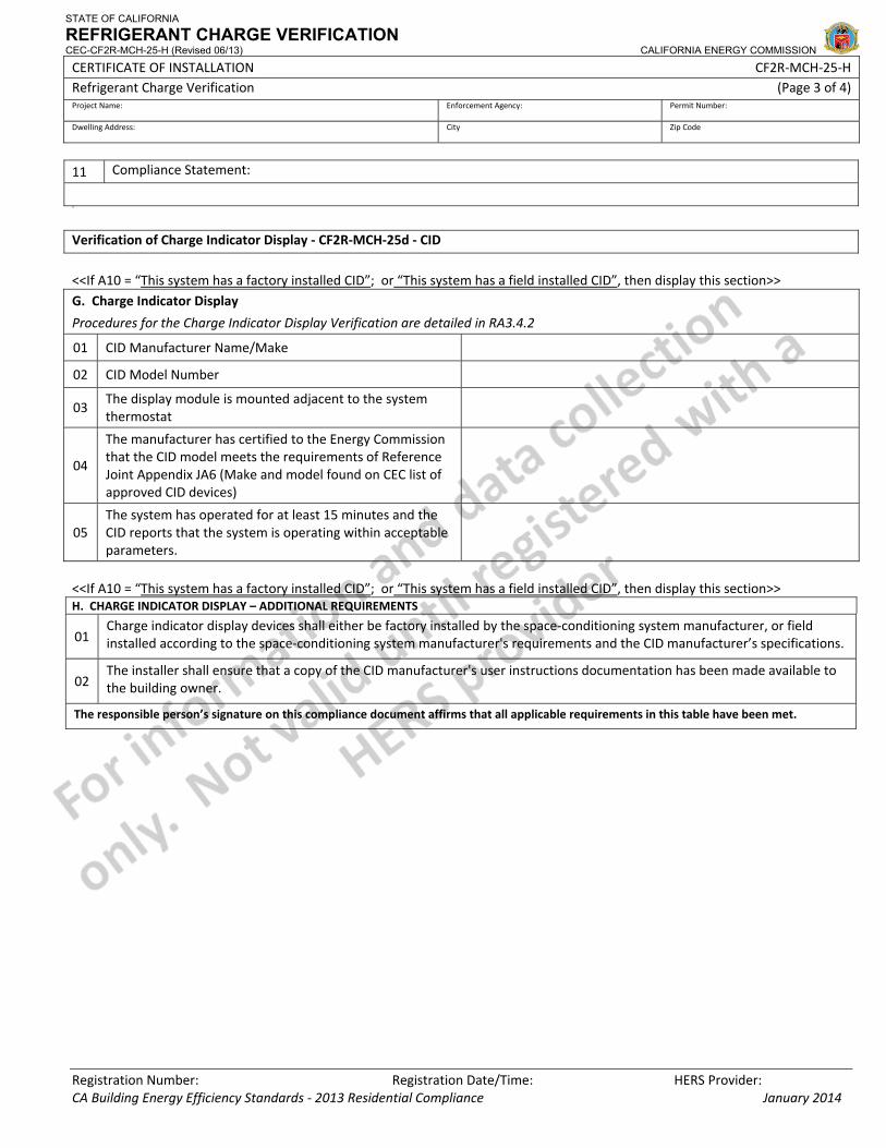
STATE OF CALIFORNIA
REFRIGERANT CHARGE VERIFICATION CEC-CF2R-MCH-25-H (Revised 06/13) CALIFORNIA ENERGY COMMISSION
CERTIFICATE OF INSTALLATION CF2R‐MCH‐25‐H Refrigerant Charge Verification (Page 3 of 4) Project Name: Enforcement Agency: Permit Number:
Dwelling Address: City Zip Code
Registration Number: Registration Date/Time: HERS Provider: CA Building Energy Efficiency Standards ‐ 2013 Residential Compliance January 2014
11 Compliance Statement:
243
Verification of Charge Indicator Display ‐ CF2R‐MCH‐25d ‐ CID
<<If A10 = “This system has a factory installed CID”; or “This system has a field installed CID”, then display this section>> G. Charge Indicator Display
Procedures for the Charge Indicator Display Verification are detailed in RA3.4.2
01 CID Manufacturer Name/Make
02 CID Model Number
03 The display module is mounted adjacent to the system thermostat
04
The manufacturer has certified to the Energy Commission that the CID model meets the requirements of Reference Joint Appendix JA6 (Make and model found on CEC list of approved CID devices)
05 The system has operated for at least 15 minutes and the CID reports that the system is operating within acceptable parameters.
<<If A10 = “This system has a factory installed CID”; or “This system has a field installed CID”, then display this section>> H. CHARGE INDICATOR DISPLAY – ADDITIONAL REQUIREMENTS
01 Charge indicator display devices shall either be factory installed by the space‐conditioning system manufacturer, or field installed according to the space‐conditioning system manufacturer's requirements and the CID manufacturer’s specifications.
02 The installer shall ensure that a copy of the CID manufacturer's user instructions documentation has been made available to the building owner.
The responsible person’s signature on this compliance document affirms that all applicable requirements in this table have been met.

STATE OF CALIFORNIA
REFRIGERANT CHARGE VERIFICATION CEC-CF2R-MCH-25-H (Revised 06/13) CALIFORNIA ENERGY COMMISSION
CERTIFICATE OF INSTALLATION CF2R‐MCH‐25‐H Refrigerant Charge Verification (Page 4 of 4) Project Name: Enforcement Agency: Permit Number:
Dwelling Address: City Zip Code
Registration Number: Registration Date/Time: HERS Provider: CA Building Energy Efficiency Standards ‐ 2013 Residential Compliance January 2014
DOCUMENTATION AUTHOR'S DECLARATION STATEMENT1. I certify that this Certificate of Installation documentation is accurate and complete.
Documentation Author Name: Documentation Author Signature:
Documentation Author Company Name: Date Signed:
Address: CEA/HERS Certification Identification (If applicable):
City/State/Zip: Phone:
RESPONSIBLE PERSON'S DECLARATION STATEMENT
I certify the following under penalty of perjury, under the laws of the State of California:
1. The information provided on this Certificate of Installation is true and correct.
2. I am eligible under Division 3 of the Business and Professions Code in the applicable classification to accept responsibility for the system design, construction, or installation of features, materials, components, or manufactured devices for the scope of work identified on this Certificate of Installation and attest to the declarations in this statement (responsible builder/installer), otherwise I am an authorized representative of the responsible builder/installer.
3. The constructed or installed features, materials, components or manufactured devices (the installation) identified on this Certificate of Installation conforms to all applicable codes and regulations, and the installation conforms to the requirements given on the plans and specifications approved by the enforcement agency.
4. I understand that a HERS rater will check the installation to verify compliance, and that if such checking identifies defects; I am required to take corrective action at my expense. I understand that Energy Commission and HERS Provider representatives will also perform quality assurance checking of installations, including those approved as part of a sample group but not checked by a HERS rater, and if those installations fail to meet the requirements of such quality assurance checking, the required corrective action and additional checking/testing of other installations in that HERS sample group will be performed at my expense.
5. I reviewed a copy of the Certificate of Compliance approved by the enforcement agency that identifies the specific requirements for the scope of construction or installation identified on this Certificate of Installation, and I have ensured that the requirements that apply to the construction or installation have been met.
6. I will ensure that a registered copy of this Certificate of Installation shall be posted, or made available with the building permit(s) issued for the building, and made available to the enforcement agency for all applicable inspections. I understand that a registered copy of this Certificate of Installation is required to be included with the documentation the builder provides to the building owner at occupancy.
Responsible Builder/Installer Name: Responsible Builder/Installer Signature:
Company Name: (Installing Subcontractor or General Contractor or Builder/Owner) Position With Company (Title):
Address: CSLB License:
City/State/Zip: Phone Date Signed:
Third Party Quality Control Program (TPQCP) Status: Name of TPQCP (if applicable):
CERTIFICATE OF INSTALLATION ‐ USER INSTRUCTIONS CF2R‐MCH‐25‐H Refrigerant Charge Verification ‐ MCH‐25a and 25d (Page 1 of 3)
CA Building Energy Efficiency Standards - 2013 Residential Compliance January 2014
Instructions MCH‐25a: Section A. System Information
1. This information is automatically pulled from the Certificate of Installation (MCH‐01). 2. This information is automatically pulled from the Certificate of Installation (MCH‐01) 3. This information is automatically pulled from the Certificate of Installation (MCH‐01). 4. This information is automatically pulled from the Certificate of Installation (MCH‐01) 5. This information is automatically pulled from the Certificate of Installation (MCH‐01). 6. This information is automatically pulled from the Certificate of Installation (MCH‐01) 7. Choose the type of refrigerant used by the system being verified. 8. If “Other” is chosen in Row A07, then indicate the type of refrigerant being used. If R‐22 or R‐410A is being used
(regardless of trade name, Puron, Genetro, etc.) it should be indicated in Row A07. This row is only for refrigerants other than R‐22 and R‐410a. Documentation of refrigerant may be requested.
9. Indicate whether the HVAC system is Completely New, Replacement or an Alteration. These are defined in detail the Residential Compliance Manual.
10. Select the appropriate choice regarding whether this system has a Charge Indicator Display (CID). Qualifying CID’s may exempt a system from HERS refrigerant charge verification. CID’s are described in Joint Appendix JA6.1. Qualifying CID’s must appear on a list of approved devices kept by the Commission.
11. Most ducted split systems and package systems are of the type that minimum airflow can be verified using an approved measurement procedure. Examples of systems that do not meet this description are ductless systems. Selecting “No” here may subject the project to additional scrutiny by enforcement personnel.
12. Most ducted split systems and package systems are of the type that approved refrigerant charge verification procedures detailed in Residential Appendix RA3.2.2 or RA1 can be used (i.e., Standard Charge Verification or Winter Setup Verification procedures). Examples of systems that may not meet this description are “mini splits” or variable refrigerant flow systems that may only be charged using weigh‐in procedures. Selecting “No” here may subject the project to additional scrutiny.
13. Specify the date the refrigerant charge verification was performed. 14. Select the refrigerant charge verification method used from the choices provided:
• Superheat (outdoor temperature must be ≥ 55 degF); This verification method can only be used when the outdoor temperature is at or above 55 degF. It is only used on systems with fixed orifice refrigerant metering devices (non‐variable metering devices). This method is detailed in Reference Appendix RA3.2.2.6.1. Systems verified using this method may be eligible for HERS verification compliance using sampling. Choosing this option will generate a CF2R‐MCH‐25a.
• Subcooling (outdoor temperature must be ≥ 55 degF); This verification method can only be used when the outdoor temperature is at or above 55 degF. It is only used on systems with variable metering devices (TXV or EXV). This method is detailed in Reference Appendix RA3.2.2.6.2. Systems verified using this method may be eligible for HERS verification compliance using sampling. Choosing this option will generate a CF2R‐MCH‐25b.
• Weigh‐in; This verification method can be used at any outdoor temperature allowed by the equipment manufacturer. This method is detailed in Reference Appendix RA3.2.3. Systems verified using this method are NOT eligible for HERS verification compliance using Group Sampling. Choosing this option will generate a CF2R‐MCH‐25c.
• Winter Setup (applicable when outdoor temperature is < 55 degF); The Winter Setup verification method is a special version of the Subcooling method. It can be used when the outdoor temperature is between 37 and 55 degF. It can only be used on equipment where the manufacturer has specifically approved it for the equipment being tested. The Winter Setup procedure is details in Residential Appendix RA1.2. Choosing this option will generate a CF2R‐MCH‐25e.
• New Package Unit Factory Charge; Choose this option when a new package unit is being installed that has an AHRI rating. This helps ensure that the unit was properly charged at the factory. HERS verification of refrigerant charge may not be required in this case. Choosing this option will generate a CF2R‐MCH‐25f.
15. Identify who will be performing the verification that is documented on this Certificate of Installation, select from the two options. Note that HERS verification compliance by Group Sampling requires that the installer perform their own refrigerant charge verification as part of the installation of the equipment prior to the system being put into a sample group for possible selection by a HERS rater for verification. If Group Sampling is not intended, the HERS Rater may perform the refrigerant charge verification on behalf of the Installing Contractor (applies to any method but Weigh‐In) and the Rater will enter same results on both the CF2R and CF3R.
CERTIFICATE OF INSTALLATION ‐ USER INSTRUCTIONS CF2R‐MCH‐25‐H Refrigerant Charge Verification ‐ MCH‐25a and 25d (Page 2 of 3)
CA Building Energy Efficiency Standards - 2013 Residential Compliance January 2014
16. The Group Sampling status is automatically displayed based on the input results of Row A14 and Row A15. Group Sampling procedures are detailed Residential Appendix RA2.3.
Section B. Metering Device Verification
1. Select the correct metering device used on the system being verified. This will check against the refrigerant charge verification method selected in Row A14. An error message will appear in Row B02 iif the wrong verification method may has been selected. Superheat verification can only be used on systems with fixed orifice and Subcool verification can only be used on systems with variable metering devices (TXV or EXV).
2. An error message in here indicates that the wrong verification method may have been selected. Superheat verification can only be used on systems with fixed orifice and Subcool verification can only be used on systems with variable metering devices (TXV or EXV).
Section C. Instrument Calibration
1. Enter the date of most recent Digital Refrigerant Gauge Calibration Field Check. Analog gauges are not allowed for verification purposes under the 2013 Standards. Specification for pressure gauges is found in Residential Appendix RA3.2.2.2.3. Procedures for the field check procedure are detailed in RA3.2.2.4.2. Calibration field check must happen at least once every 30 days.
2. Enter the date of the most recent Digital Thermocouple Calibration. Specifications for thermocouples and temperature sensors can be found in Residential Appendix RA3.2.2.2.2. Procedures for calibration are detailed in RA3.2.2.4.1. Calibration must happen at least once every 30 days.
3. Digital Refrigerant Gauge Calibration status will appear automatically. If the date entered in Row C01 is more than 30 days prior to date of verification this row will indicate that calibration is required and you will not be allowed to continue filling out this document.
4. Digital Thermocouple Calibration status will appear automatically. If the date entered in Row C02 is more than 30 days prior to date of verification this row will indicate that calibration is required and you will not be allowed to continue filling out this document.
Section D. Measurement Access Hole (MAH) Verification
1. Indicate the method used to demonstrate compliance with the MAH requirement by selecting the appropriate method from the drop down list. Procedures for installing MAH’s are detailed in RA3.2.2.3. Selecting that the MAH cannot be installed consistent with Figure 3.2‐1 may result in additional scrutiny by enforcement personnel.
Section E. Minimum System Airflow Rate Verification
1. This information is automatically calculated based on the information given in line A09. This is the target minimum system airflow required for the system being verified.
2. This information is automatically calculated based on the MCH‐23 which documents the measured airflow of the system being verified. If the measured airflow is not adequate it will not comply with the airflow requirements and refrigerant charge verification cannot be performed.
Section F. Superheat Charge Verification Method – Data Collection
1. Measure and record the lowest return air dry‐bulb temperature that occurred during the refrigerant charge procedure in degrees F. This temperature must remain above 70 degF during the verification procedure. This requirement is detailed in Residential Appendix RA3.2.2.5.
2. Measure and record the condenser air dry‐bulb temperature (Tcondenser) in degrees F. This value is used to determine the target superheat from table RA3.2‐2. This value must be at least 55 degF and no more than 115 degF to use the Superheat Charge Verification Method.
3. If a value less than 55 degF or greater than 115 degF is entered in Row F02 the Superheat Method cannot be used. 4. Measure and record the return air dry‐bulb temperature (Treturn,db) in degrees F. This measurement is taken at the MAH (or
alternate location specified in Row F01. This procedure is detailed in RA3.2.2.5.
CERTIFICATE OF INSTALLATION ‐ USER INSTRUCTIONS CF2R‐MCH‐25‐H Refrigerant Charge Verification ‐ MCH‐25a and 25d (Page 3 of 3)
CA Building Energy Efficiency Standards - 2013 Residential Compliance January 2014
5. Measure and record the return air wet‐bulb temperature (Treturn,wb) in degrees F. This measurement is taken at the MAH (or alternate location specified in Row F01. This procedure is detailed in RA3.2.2.5. This value is used to determine the target superheat from table RA3.2‐2.
6. Measure and record the suction line temperature (Tsuction) in degrees F. This procedure is detailed in RA3.2.2.5. This value is used to calculate the measured superheat.
7. Measure and record the suction line pressure (Psuction) in psig. This procedure is detailed in RA3.2.2.5. This value is used to determine the evaporator saturation temperature (Tevaporator,sat) from a pressure temperature chart for the appropriate refrigerant (can be internal to a digital gauge), which is entered into Row F08.
8. Enter the evaporator saturation temperature (Tevaporator,sat) from the digital gauge or a separate pressure‐temperature chart that corresponds to the suction line pressure entered in Row F07, in degrees F.
9. Measured superheat is automatically calculated as the difference between the suction line temperature (Row F06) and the evaporator saturation temperature (Row F08)
10. Enter target superheat from Table RA3.2‐2. This table requires values for the condenser air dry bulb temperature (Row F02) and the return air wet bulb temperature (Row F05)
11. System passes superheat method when Row F10 is within plus or minus 5 degrees of Row F09. Section G. Verification of Charge Indicator Display
1. Enter the manufacturer name or make of the approved Charge Indicator Display. Must match name shown on the list of approved devices kept by the Commission.
2. Enter the manufacturer model number of the approved Charge Indicator Display. Must match name shown on the list of approved devices kept by the Commission.
3. The installer must confirm that the CID display module is mounted adjacent to thermostat that controls the system being verified. This requirement is detailed in Residential Appendix RA3.4.2.
4. The installer must confirm that the installed CID is approved and appears the list of approved devices kept by the Commission. This requirement is detailed in Residential Appendix RA3.4.2.
5. The installer must confirm that the system has operated for at least 15 minutes and that they system is operating within acceptable parameters as specified by the CID and equipment manufacturers. This requirement is detailed in Residential Appendix RA3.4.2.
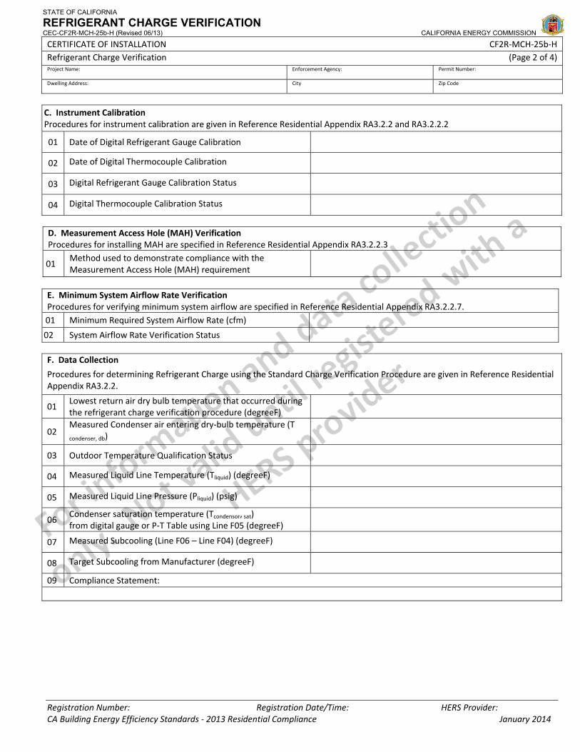
STATE OF CALIFORNIA
REFRIGERANT CHARGE VERIFICATION CEC-CF2R-MCH-25b-H (Revised 06/13) CALIFORNIA ENERGY COMMISSION
CERTIFICATE OF INSTALLATION CF2R‐MCH‐25b‐H Refrigerant Charge Verification (Page 2 of 4) Project Name: Enforcement Agency: Permit Number:
Dwelling Address: City Zip Code
Registration Number: Registration Date/Time: HERS Provider: CA Building Energy Efficiency Standards ‐ 2013 Residential Compliance January 2014
C. Instrument Calibration Procedures for instrument calibration are given in Reference Residential Appendix RA3.2.2 and RA3.2.2.2
01 Date of Digital Refrigerant Gauge Calibration
02 Date of Digital Thermocouple Calibration
03 Digital Refrigerant Gauge Calibration Status
04 Digital Thermocouple Calibration Status
D. Measurement Access Hole (MAH) VerificationProcedures for installing MAH are specified in Reference Residential Appendix RA3.2.2.3
01 Method used to demonstrate compliance with the Measurement Access Hole (MAH) requirement
E. Minimum System Airflow Rate Verification Procedures for verifying minimum system airflow are specified in Reference Residential Appendix RA3.2.2.7. 01 Minimum Required System Airflow Rate (cfm)
02 System Airflow Rate Verification Status F. Data Collection
Procedures for determining Refrigerant Charge using the Standard Charge Verification Procedure are given in Reference Residential Appendix RA3.2.2.
01 Lowest return air dry bulb temperature that occurred during the refrigerant charge verification procedure (degreeF)
02 Measured Condenser air entering dry‐bulb temperature (T condenser, db)
03 Outdoor Temperature Qualification Status
04 Measured Liquid Line Temperature (Tliquid) (degreeF)
05 Measured Liquid Line Pressure (Pliquid) (psig)
06 Condenser saturation temperature (Tcondensor, sat) from digital gauge or P‐T Table using Line F05 (degreeF)
07 Measured Subcooling (Line F06 – Line F04) (degreeF)
08 Target Subcooling from Manufacturer (degreeF)
09 Compliance Statement:
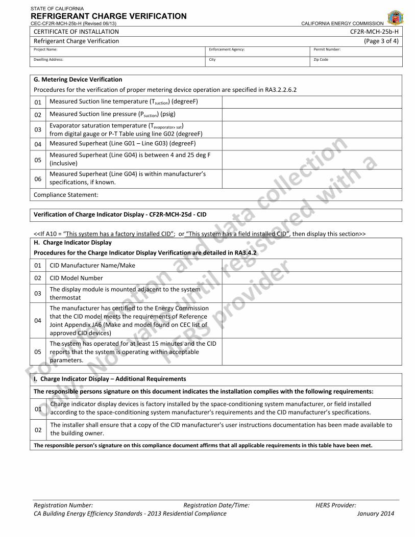
STATE OF CALIFORNIA
REFRIGERANT CHARGE VERIFICATION CEC-CF2R-MCH-25b-H (Revised 06/13) CALIFORNIA ENERGY COMMISSION
CERTIFICATE OF INSTALLATION CF2R‐MCH‐25b‐H Refrigerant Charge Verification (Page 3 of 4) Project Name: Enforcement Agency: Permit Number:
Dwelling Address: City Zip Code
Registration Number: Registration Date/Time: HERS Provider: CA Building Energy Efficiency Standards ‐ 2013 Residential Compliance January 2014
G. Metering Device Verification
Procedures for the verification of proper metering device operation are specified in RA3.2.2.6.2
01 Measured Suction line temperature (Tsuction) (degreeF)
02 Measured Suction line pressure (Psuction) (psig)
03 Evaporator saturation temperature (Tevaporator, sat) from digital gauge or P‐T Table using line G02 (degreeF)
04 Measured Superheat (Line G01 – Line G03) (degreeF)
05 Measured Superheat (Line G04) is between 4 and 25 deg F (inclusive)
06 Measured Superheat (Line G04) is within manufacturer’s specifications, if known.
Compliance Statement:
Verification of Charge Indicator Display ‐ CF2R‐MCH‐25d ‐ CID
<<If A10 = “This system has a factory installed CID”; or “This system has a field installed CID”, then display this section>> H. Charge Indicator Display
Procedures for the Charge Indicator Display Verification are detailed in RA3.4.2
01 CID Manufacturer Name/Make
02 CID Model Number
03 The display module is mounted adjacent to the system thermostat
04
The manufacturer has certified to the Energy Commission that the CID model meets the requirements of Reference Joint Appendix JA6 (Make and model found on CEC list of approved CID devices)
05 The system has operated for at least 15 minutes and the CID reports that the system is operating within acceptable parameters.
I. Charge Indicator Display – Additional Requirements
The responsible persons signature on this document indicates the installation complies with the following requirements:
01 Charge indicator display devices is factory installed by the space‐conditioning system manufacturer, or field installed according to the space‐conditioning system manufacturer's requirements and the CID manufacturer’s specifications.
02 The installer shall ensure that a copy of the CID manufacturer's user instructions documentation has been made available to the building owner.
The responsible person’s signature on this compliance document affirms that all applicable requirements in this table have been met.
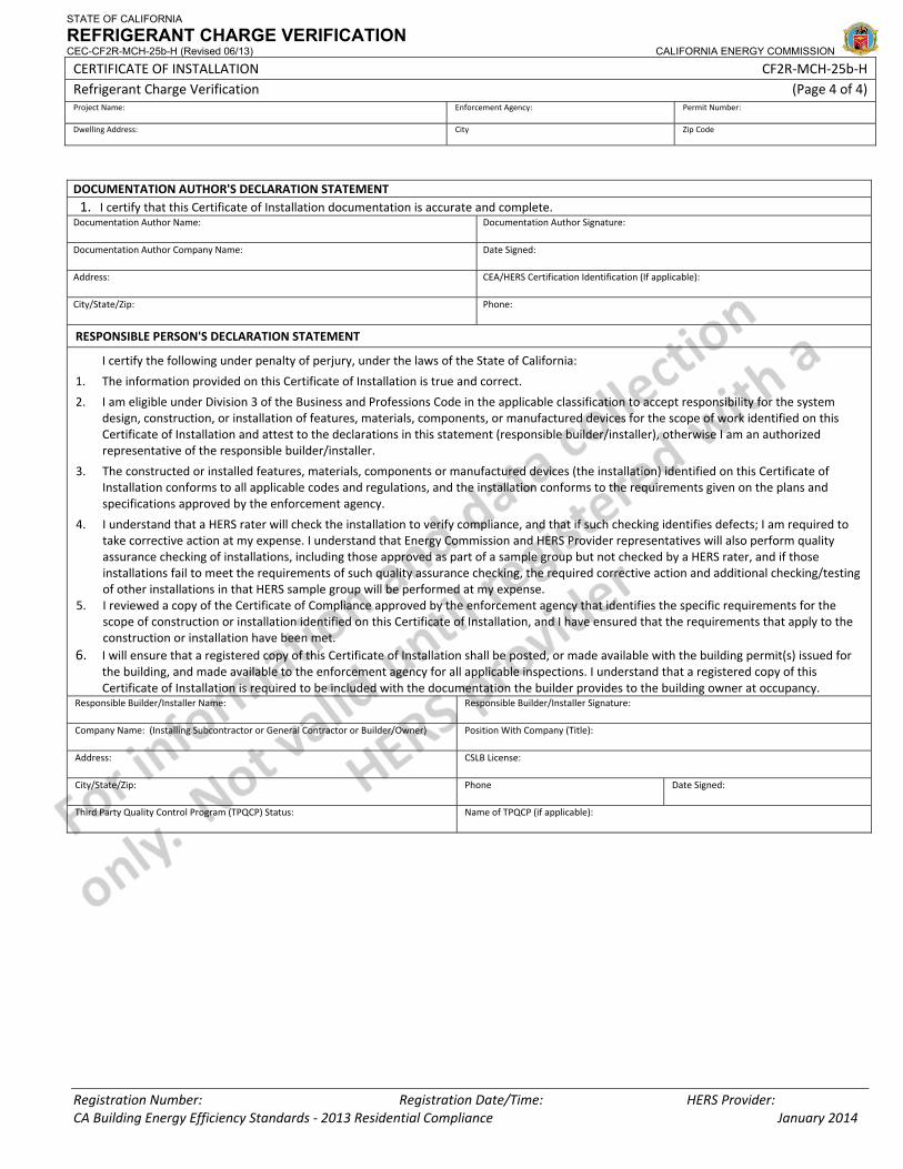
STATE OF CALIFORNIA
REFRIGERANT CHARGE VERIFICATION CEC-CF2R-MCH-25b-H (Revised 06/13) CALIFORNIA ENERGY COMMISSION
CERTIFICATE OF INSTALLATION CF2R‐MCH‐25b‐H Refrigerant Charge Verification (Page 4 of 4) Project Name: Enforcement Agency: Permit Number:
Dwelling Address: City Zip Code
Registration Number: Registration Date/Time: HERS Provider: CA Building Energy Efficiency Standards ‐ 2013 Residential Compliance January 2014
DOCUMENTATION AUTHOR'S DECLARATION STATEMENT1. I certify that this Certificate of Installation documentation is accurate and complete.
Documentation Author Name: Documentation Author Signature:
Documentation Author Company Name: Date Signed:
Address: CEA/HERS Certification Identification (If applicable):
City/State/Zip: Phone:
RESPONSIBLE PERSON'S DECLARATION STATEMENT
I certify the following under penalty of perjury, under the laws of the State of California:
1. The information provided on this Certificate of Installation is true and correct.
2. I am eligible under Division 3 of the Business and Professions Code in the applicable classification to accept responsibility for the system design, construction, or installation of features, materials, components, or manufactured devices for the scope of work identified on this Certificate of Installation and attest to the declarations in this statement (responsible builder/installer), otherwise I am an authorized representative of the responsible builder/installer.
3. The constructed or installed features, materials, components or manufactured devices (the installation) identified on this Certificate of Installation conforms to all applicable codes and regulations, and the installation conforms to the requirements given on the plans and specifications approved by the enforcement agency.
4. I understand that a HERS rater will check the installation to verify compliance, and that if such checking identifies defects; I am required to take corrective action at my expense. I understand that Energy Commission and HERS Provider representatives will also perform quality assurance checking of installations, including those approved as part of a sample group but not checked by a HERS rater, and if those installations fail to meet the requirements of such quality assurance checking, the required corrective action and additional checking/testing of other installations in that HERS sample group will be performed at my expense.
5. I reviewed a copy of the Certificate of Compliance approved by the enforcement agency that identifies the specific requirements for the scope of construction or installation identified on this Certificate of Installation, and I have ensured that the requirements that apply to the construction or installation have been met.
6. I will ensure that a registered copy of this Certificate of Installation shall be posted, or made available with the building permit(s) issued for the building, and made available to the enforcement agency for all applicable inspections. I understand that a registered copy of this Certificate of Installation is required to be included with the documentation the builder provides to the building owner at occupancy.
Responsible Builder/Installer Name: Responsible Builder/Installer Signature:
Company Name: (Installing Subcontractor or General Contractor or Builder/Owner) Position With Company (Title):
Address: CSLB License:
City/State/Zip: Phone Date Signed:
Third Party Quality Control Program (TPQCP) Status: Name of TPQCP (if applicable):
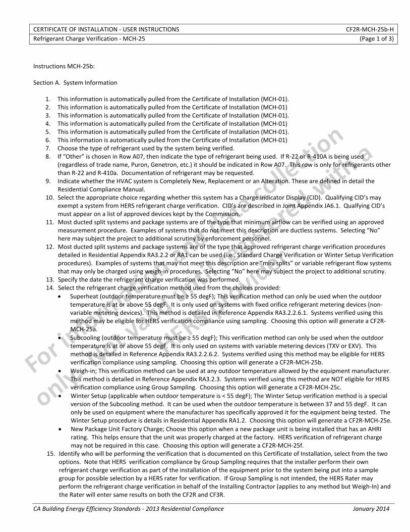
CERTIFICATE OF INSTALLATION ‐ USER INSTRUCTIONS CF2R‐MCH‐25b‐H Refrigerant Charge Verification ‐ MCH‐25 (Page 1 of 3)
CA Building Energy Efficiency Standards ‐ 2013 Residential Compliance January 2014
Instructions MCH‐25b: Section A. System Information
1. This information is automatically pulled from the Certificate of Installation (MCH‐01). 2. This information is automatically pulled from the Certificate of Installation (MCH‐01) 3. This information is automatically pulled from the Certificate of Installation (MCH‐01). 4. This information is automatically pulled from the Certificate of Installation (MCH‐01) 5. This information is automatically pulled from the Certificate of Installation (MCH‐01). 6. This information is automatically pulled from the Certificate of Installation (MCH‐01) 7. Choose the type of refrigerant used by the system being verified. 8. If “Other” is chosen in Row A07, then indicate the type of refrigerant being used. If R‐22 or R‐410A is being used
(regardless of trade name, Puron, Genetron, etc.) it should be indicated in Row A07. This row is only for refrigerants other than R‐22 and R‐410a. Documentation of refrigerant may be requested.
9. Indicate whether the HVAC system is Completely New, Replacement or an Alteration. These are defined in detail the Residential Compliance Manual.
10. Select the appropriate choice regarding whether this system has a Charge Indicator Display (CID). Qualifying CID’s may exempt a system from HERS refrigerant charge verification. CID’s are described in Joint Appendix JA6.1. Qualfying CID’s must appear on a list of approved devices kept by the Commission.
11. Most ducted split systems and package systems are of the type that minimum airflow can be verified using an approved measurement procedure. Examples of systems that do not meet this description are ductless systems. Selecting “No” here may subject the project to additional scrutiny by enforcement personnel.
12. Most ducted split systems and package systems are of the type that approved refrigerant charge verification procedures detailed in Residential Appendix RA3.2.2 or RA1 can be used (i.e., Standard Charge Verification or Winter Setup Verification procedures). Examples of systems that may not meet this description are “mini splits” or variable refrigerant flow systems that may only be charged using weigh‐in procedures. Selecting “No” here may subject the project to additional scrutiny.
13. Specify the date the refrigerant charge verification was performed. 14. Select the refrigerant charge verification method used from the choices provided:
• Superheat (outdoor temperature must be ≥ 55 degF); This verification method can only be used when the outdoor temperature is at or above 55 degF. It is only used on systems with fixed orifice refrigerant metering devices (non‐variable metering devices). This method is detailed in Reference Appendix RA3.2.2.6.1. Systems verified using this method may be eligible for HERS verification compliance using sampling. Choosing this option will generate a CF2R‐MCH‐25a.
• Subcooling (outdoor temperature must be ≥ 55 degF); This verification method can only be used when the outdoor temperature is at or above 55 degF. It is only used on systems with variable metering devices (TXV or EXV). This method is detailed in Reference Appendix RA3.2.2.6.2. Systems verified using this method may be eligible for HERS verification compliance using sampling. Choosing this option will generate a CF2R‐MCH‐25b.
• Weigh‐in; This verification method can be used at any outdoor temperature allowed by the equipment manufacturer. This method is detailed in Reference Appendix RA3.2.3. Systems verified using this method are NOT eligible for HERS verification compliance using Group Sampling. Choosing this option will generate a CF2R‐MCH‐25c.
• Winter Setup (applicable when outdoor temperature is < 55 degF); The Winter Setup verification method is a special version of the Subcooling method. It can be used when the outdoor temperature is between 37 and 55 degF. It can only be used on equipment where the manufacturer has specifically approved it for the equipment being tested. The Winter Setup procedure is details in Residential Appendix RA1.2. Choosing this option will generate a CF2R‐MCH‐25e.
• New Package Unit Factory Charge; Choose this option when a new package unit is being installed that has an AHRI rating. This helps ensure that the unit was properly charged at the factory. HERS verification of refrigerant charge may not be required in this case. Choosing this option will generate a CF2R‐MCH‐25f.
15. Identify who will be performing the verification that is documented on this Certificate of Installation, select from the two options. Note that HERS verification compliance by Group Sampling requires that the installer perform their own refrigerant charge verification as part of the installation of the equipment prior to the system being put into a sample group for possible selection by a HERS rater for verification. If Group Sampling is not intended, the HERS Rater may perform the refrigerant charge verification in behalf of the Installing Contractor (applies to any method but Weigh‐In) and the Rater will enter same results on both the CF2R and CF3R.
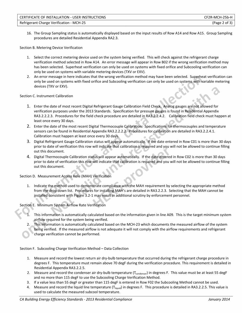
CERTIFICATE OF INSTALLATION ‐ USER INSTRUCTIONS CF2R‐MCH‐25b‐H Refrigerant Charge Verification ‐ MCH‐25 (Page 2 of 3)
CA Building Energy Efficiency Standards ‐ 2013 Residential Compliance January 2014
16. The Group Sampling status is automatically displayed based on the input results of Row A14 and Row A15. Group Sampling procedures are detailed Residential Appendix RA2.3.
Section B. Metering Device Verification
1. Select the correct metering device used on the system being verified. This will check against the refrigerant charge verification method selected in Row A14. An error message will appear in Row B02 if the wrong verification method may has been selected. Superheat verification can only be used on systems with fixed orifice and Subcooling verification can only be used on systems with variable metering devices (TXV or EXV).
2. An error message in here indicates that the wrong verification method may have been selected. Superheat verification can only be used on systems with fixed orifice and Subcooling verification can only be used on systems with variable metering devices (TXV or EXV).
Section C. Instrument Calibration
1. Enter the date of most recent Digital Refrigerant Gauge Calibration Field Check. Analog gauges are not allowed for verification purposes under the 2013 Standards. Specification for pressure gauges is found in Residential Appendix RA3.2.2.2.3. Procedures for the field check procedure are detailed in RA3.2.2.4.2. Calibration field check must happen at least once every 30 days.
2. Enter the date of the most recent Digital Thermocouple Calibration. Specifications for thermocouples and temperature sensors can be found in Residential Appendix RA3.2.2.2.2. Procedures for calibration are detailed in RA3.2.2.4.1. Calibration must happen at least once every 30 days.
3. Digital Refrigerant Gauge Calibration status will appear automatically. If the date entered in Row C01 is more than 30 days prior to date of verification this row will indicate that calibration is required and you will not be allowed to continue filling out this document.
4. Digital Thermocouple Calibration status will appear automatically. If the date entered in Row C02 is more than 30 days prior to date of verification this row will indicate that calibration is required and you will not be allowed to continue filling out this document.
Section D. Measurement Access Hole (MAH) Verification
1. Indicate the method used to demonstrate compliance with the MAH requirement by selecting the appropriate method from the drop down list. Procedures for installing MAH’s are detailed in RA3.2.2.3. Selecting that the MAH cannot be installed consistent with Figure 3.2‐1 may result in additional scrutiny by enforcement personnel.
Section E. Minimum System Airflow Rate Verification
1. This information is automatically calculated based on the information given in line A09. This is the target minimum system airflow required for the system being verified.
2. This information is automatically calculated based on the MCH‐23 which documents the measured airflow of the system being verified. If the measured airflow is not adequate it will not comply with the airflow requirements and refrigerant charge verification cannot be performed.
Section F. Subcooling Charge Verification Method – Data Collection
1. Measure and record the lowest return air dry‐bulb temperature that occurred during the refrigerant charge procedure in degrees F. This temperature must remain above 70 degF during the verification procedure. This requirement is detailed in Residential Appendix RA3.2.2.5.
2. Measure and record the condenser air dry‐bulb temperature (Tcondenser) in degrees F. This value must be at least 55 degF and no more than 115 degF to use the Subcooling Charge Verification Method.
3. If a value less than 55 degF or greater than 115 degF is entered in Row F02 the Subcooling Method cannot be used. 4. Measure and record the liquid line temperature (Tliquid) in degrees F. This procedure is detailed in RA3.2.2.5. This value is
used to calculate the measured subcool temperature.
CERTIFICATE OF INSTALLATION ‐ USER INSTRUCTIONS CF2R‐MCH‐25b‐H Refrigerant Charge Verification ‐ MCH‐25 (Page 3 of 3)
CA Building Energy Efficiency Standards ‐ 2013 Residential Compliance January 2014
5. Measure and record the liquid line pressure (Pliquid) in psig. This procedure is detailed in RA3.2.2.5. This value is used to determine the condenser saturation temperature (Tcondenser,sat) from a pressure temperature chart for the appropriate refrigerant (can be internal to a digital gauge), which is entered into Row F06.
6. Enter the condenser saturation temperature (Tcondenser,sat) from the digital gauge or a separate pressure‐temperature chart that corresponds to the liquid line pressure entered in Row F05, in degrees F.
7. Measured Subcooling is automatically calculated as the difference between the liquid line temperature (Row F04) and the condenser saturation temperature (Row F06)
8. Enter target subcooling from manufacturer. This may be a challenge to find for older equipment. Internet searches can sometimes result in archived equipment specifications for the equipment in question, or sometimes a very similar model. If the manufacturer’s target cannot be found the Commission’s Executive Director may provide additional guidance for compliance.
9. System passes Subcooling method when Row F08 is within plus or minus 5 degrees of Row F07. Section G. Metering Device Verification
1. Measure and record the suction line temperature (Tsuction) in degrees F. This procedure is detailed in RA3.2.2.5. This value is used to calculate the measured superheat.
2. Measure and record the suction line pressure (Psuction) in psig. This procedure is detailed in RA3.2.2.5. This value is used to determine the evaporator saturation temperature (Tevaporator,sat) from a pressure temperature chart for the appropriate refrigerant (can be internal to a digital gauge), which is entered into Row G03.
3. Enter the evaporator saturation temperature (Tevaporator,sat) from the digital gauge or a separate pressure‐temperature chart that corresponds to the suction line pressure entered in Row G02, in degrees F.
4. Measured superheat is automatically calculated as the difference between the suction line temperature (Row G01) and the evaporator saturation temperature (Row G03)
5. There are two possible criteria for passing. If the manufacturer’s specification is known it should be used, otherwise the CEC requirement is that the superheat be between 4 and 25 degF, inclusive. This row checks the CEC requirement.
6. If the manufacturer’s target superheat for ensuring proper metering device operation is known, it supersedes the CEC requirement of being between 4 and 25 degF. If “Yes, documentation to be provided upon request.” is selected, the installer should be prepared to provide documentation for the target values used.
7. There are two possible criteria for passing. If the manufacturer’s specification is known it should be used, otherwise the CEC requirement is that the superheat be between 4 and 25 degF, inclusive. If “Yes, documentation to be provided upon request.” is selected in Row G06, the installer should be prepared to provide documentation for the target values used.
Section H. Verification of Charge Indicator Display
1. Enter the manufacturer name or make of the approved Charge Indicator Display. Must match name shown on the list of approved devices kept by the Commission.
2. Enter the manufacturer model number of the approved Charge Indicator Display. Must match name shown on the list of approved devices kept by the Commission.
3. The installer must confirm that the CID display module is mounted adjacent to thermostat that controls the system being verified. This requirement is detailed in Residential Appendix RA3.4.2.
4. The installer must confirm that the installed CID is approved and appears the list of approved devices kept by the Commission. This requirement is detailed in Residential Appendix RA3.4.2.
5. The installer must confirm that the system has operated for at least 15 minutes and that they system is operating within acceptable parameters as specified by the CID and equipment manufacturers. This requirement is detailed in Residential Appendix RA3.4.2.
CERTIFICATE OF INSTALLATION ‐ DATA FIELD DEFINITIONS AND CALCULATIONS CF2R‐MCH‐25b‐H Refrigerant Charge Verification ‐ MCH‐25 (Page 5 of 5)
CA Building Energy Efficiency Standards ‐ 2013 Residential Compliance January 2014
I. Charge Indicator Display – Additional Requirements
The responsible persons signature on this document indicates the installation complies with the following requirements:
01 Charge indicator display devices is factory installed by the space‐conditioning system manufacturer, or field installed according to the space‐conditioning system manufacturer's requirements and the CID manufacturer’s specifications.
02 The installer shall ensure that a copy of the CID manufacturer's user instructions documentation has been made available to the building owner.
The responsible person’s signature on this compliance document affirms that all applicable requirements in this table have been met.
DOCUMENTATION AUTHOR'S DECLARATION STATEMENT
1. I certify that this Certificate of Installation documentation is accurate and complete. Documentation Author Name: Documentation Author Signature:
Documentation Author Company Name: Date Signed:
Address: CEA/HERS Certification Identification (If applicable):
City/State/Zip: Phone:
RESPONSIBLE PERSON'S DECLARATION STATEMENT
I certify the following under penalty of perjury, under the laws of the State of California:
1. The information provided on this Certificate of Installation is true and correct.
2. I am eligible under Division 3 of the Business and Professions Code to accept responsibility for the scope of construction or installation, in the applicable classification, for the scope of work specified on this Certificate of Installation (responsible builder/installer), otherwise I am an authorized representative of the responsible builder/installer.
3. The constructed or installed features, materials, components or manufactured devices (the installation) identified on this Certificate of Installation conforms to all applicable codes and regulations, and the installation conforms to the requirements given on the plans and specifications approved by the enforcement agency.
4. I understand that a HERS rater will check the installation to verify compliance, and that if such checking identifies defects; I am required to take corrective action at my expense. I understand that Energy Commission and HERS Provider representatives will also perform quality assurance checking of installations, including those approved as part of a sample group but not checked by a HERS rater, and if those installations fail to meet the requirements of such quality assurance checking, the required corrective action and additional checking/testing of other installations in that HERS sample group will be performed at my expense.
5. I reviewed a copy of the Certificate of Compliance approved by the enforcement agency that identifies the specific requirements for the scope of construction or installation identified on this Certificate of Installation, and I have ensured that the requirements that apply to the construction or installation have been met.
6. I will ensure that a registered copy of this Certificate of Installation shall be posted, or made available with the building permit(s) issued for the building, and made available to the enforcement agency for all applicable inspections. I understand that a registered copy of this Certificate of Installation is required to be included with the documentation the builder provides to the building owner at occupancy.
Responsible Builder/Installer Name: Responsible Builder/Installer Signature:
Company Name: (Installing Subcontractor or General Contractor or Builder/Owner) Position With Company (Title):
Address: CSLB License:
City/State/Zip: Phone Date Signed:
Third Party Quality Control Program (TPQCP) Status: Name of TPQCP (if applicable):
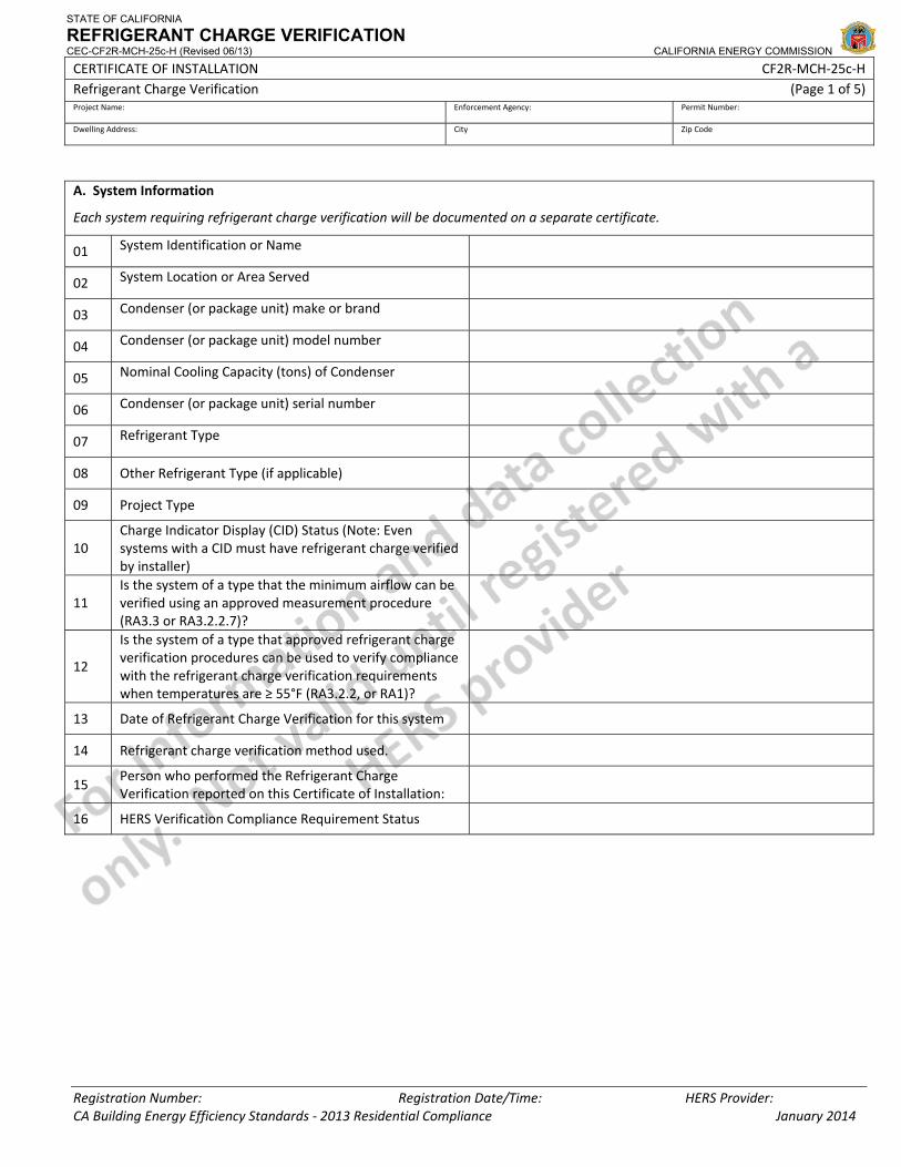
STATE OF CALIFORNIA
REFRIGERANT CHARGE VERIFICATION CEC-CF2R-MCH-25c-H (Revised 06/13) CALIFORNIA ENERGY COMMISSION
CERTIFICATE OF INSTALLATION CF2R‐MCH‐25c‐H Refrigerant Charge Verification (Page 1 of 5) Project Name: Enforcement Agency: Permit Number:
Dwelling Address: City Zip Code
Registration Number: Registration Date/Time: HERS Provider: CA Building Energy Efficiency Standards ‐ 2013 Residential Compliance January 2014
A. System Information
Each system requiring refrigerant charge verification will be documented on a separate certificate.
01 System Identification or Name
02 System Location or Area Served
03 Condenser (or package unit) make or brand
04 Condenser (or package unit) model number
05 Nominal Cooling Capacity (tons) of Condenser
06 Condenser (or package unit) serial number
07 Refrigerant Type
08 Other Refrigerant Type (if applicable)
09 Project Type
10 Charge Indicator Display (CID) Status (Note: Even systems with a CID must have refrigerant charge verified by installer)
11 Is the system of a type that the minimum airflow can be verified using an approved measurement procedure (RA3.3 or RA3.2.2.7)?
12
Is the system of a type that approved refrigerant charge verification procedures can be used to verify compliance with the refrigerant charge verification requirements when temperatures are ≥ 55°F (RA3.2.2, or RA1)?
13 Date of Refrigerant Charge Verification for this system
14 Refrigerant charge verification method used.
15 Person who performed the Refrigerant Charge Verification reported on this Certificate of Installation:
16 HERS Verification Compliance Requirement Status
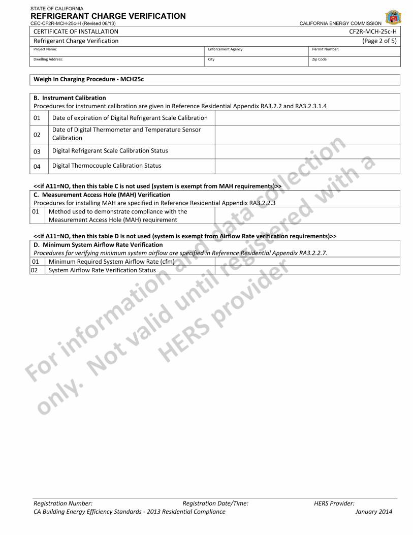
STATE OF CALIFORNIA
REFRIGERANT CHARGE VERIFICATION CEC-CF2R-MCH-25c-H (Revised 06/13) CALIFORNIA ENERGY COMMISSION
CERTIFICATE OF INSTALLATION CF2R‐MCH‐25c‐H Refrigerant Charge Verification (Page 2 of 5) Project Name: Enforcement Agency: Permit Number:
Dwelling Address: City Zip Code
Registration Number: Registration Date/Time: HERS Provider: CA Building Energy Efficiency Standards ‐ 2013 Residential Compliance January 2014
Weigh In Charging Procedure ‐ MCH25c
B. Instrument Calibration Procedures for instrument calibration are given in Reference Residential Appendix RA3.2.2 and RA3.2.3.1.4
01 Date of expiration of Digital Refrigerant Scale Calibration
02 Date of Digital Thermometer and Temperature Sensor Calibration
03 Digital Refrigerant Scale Calibration Status
04 Digital Thermocouple Calibration Status
<<if A11=NO, then this table C is not used (system is exempt from MAH requirements)>> C. Measurement Access Hole (MAH) VerificationProcedures for installing MAH are specified in Reference Residential Appendix RA3.2.2.3 01 Method used to demonstrate compliance with the
Measurement Access Hole (MAH) requirement <<if A11=NO, then this table D is not used (system is exempt from Airflow Rate verification requirements)>> D. Minimum System Airflow Rate Verification Procedures for verifying minimum system airflow are specified in Reference Residential Appendix RA3.2.2.7. 01 Minimum Required System Airflow Rate (cfm) 02 System Airflow Rate Verification Status
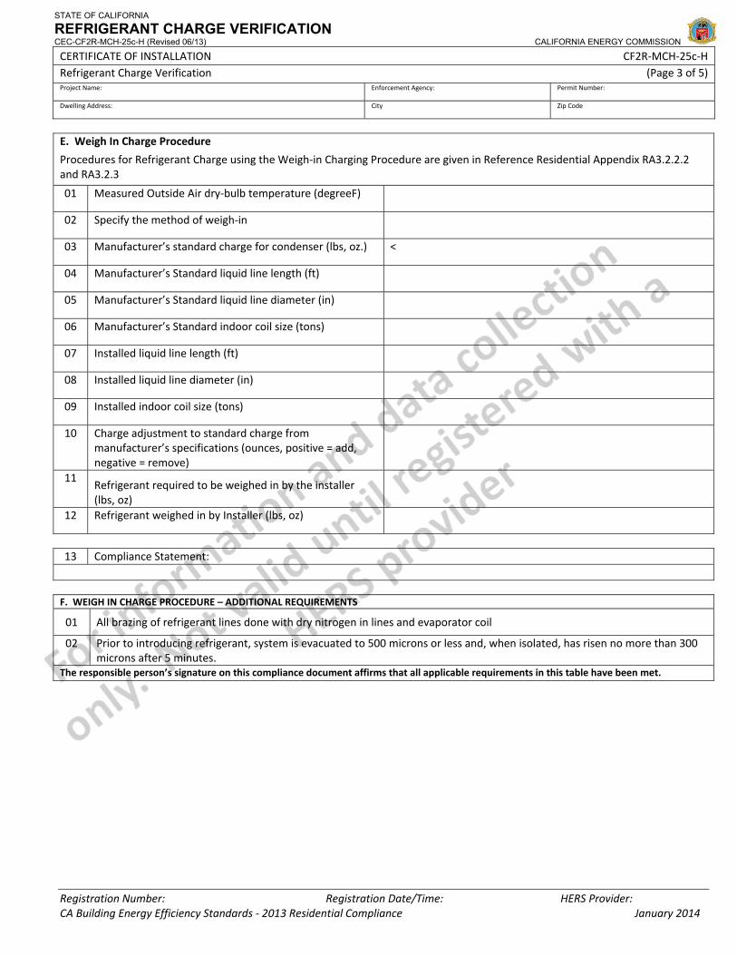
STATE OF CALIFORNIA
REFRIGERANT CHARGE VERIFICATION CEC-CF2R-MCH-25c-H (Revised 06/13) CALIFORNIA ENERGY COMMISSION
CERTIFICATE OF INSTALLATION CF2R‐MCH‐25c‐H Refrigerant Charge Verification (Page 3 of 5) Project Name: Enforcement Agency: Permit Number:
Dwelling Address: City Zip Code
Registration Number: Registration Date/Time: HERS Provider: CA Building Energy Efficiency Standards ‐ 2013 Residential Compliance January 2014
E. Weigh In Charge Procedure
Procedures for Refrigerant Charge using the Weigh‐in Charging Procedure are given in Reference Residential Appendix RA3.2.2.2 and RA3.2.3
01 Measured Outside Air dry‐bulb temperature (degreeF)
02 Specify the method of weigh‐in
03 Manufacturer’s standard charge for condenser (lbs, oz.) <
04 Manufacturer’s Standard liquid line length (ft)
05 Manufacturer’s Standard liquid line diameter (in)
06 Manufacturer’s Standard indoor coil size (tons)
07 Installed liquid line length (ft)
08 Installed liquid line diameter (in)
09 Installed indoor coil size (tons)
10 Charge adjustment to standard charge from manufacturer’s specifications (ounces, positive = add, negative = remove)
11 Refrigerant required to be weighed in by the installer (lbs, oz)
12 Refrigerant weighed in by Installer (lbs, oz)
13 Compliance Statement: F. WEIGH IN CHARGE PROCEDURE – ADDITIONAL REQUIREMENTS
01 All brazing of refrigerant lines done with dry nitrogen in lines and evaporator coil
02 Prior to introducing refrigerant, system is evacuated to 500 microns or less and, when isolated, has risen no more than 300 microns after 5 minutes.
The responsible person’s signature on this compliance document affirms that all applicable requirements in this table have been met.
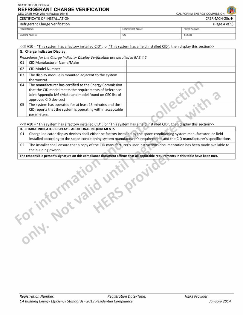
STATE OF CALIFORNIA
REFRIGERANT CHARGE VERIFICATION CEC-CF2R-MCH-25c-H (Revised 06/13) CALIFORNIA ENERGY COMMISSION
CERTIFICATE OF INSTALLATION CF2R‐MCH‐25c‐H Refrigerant Charge Verification (Page 4 of 5) Project Name: Enforcement Agency: Permit Number:
Dwelling Address: City Zip Code
Registration Number: Registration Date/Time: HERS Provider: CA Building Energy Efficiency Standards ‐ 2013 Residential Compliance January 2014
<<If A10 = “This system has a factory installed CID”; or “This system has a field installed CID”, then display this section>> G. Charge Indicator Display
Procedures for the Charge Indicator Display Verification are detailed in RA3.4.2 01 CID Manufacturer Name/Make
02 CID Model Number
03 The display module is mounted adjacent to the system thermostat
04 The manufacturer has certified to the Energy Commission that the CID model meets the requirements of Reference Joint Appendix JA6 (Make and model found on CEC list of approved CID devices)
05 The system has operated for at least 15 minutes and the CID reports that the system is operating within acceptable parameters.
<<If A10 = “This system has a factory installed CID”; or “This system has a field installed CID”, then display this section>> H. CHARGE INDICATOR DISPLAY – ADDITIONAL REQUIREMENTS 01 Charge indicator display devices shall either be factory installed by the space‐conditioning system manufacturer, or field
installed according to the space‐conditioning system manufacturer's requirements and the CID manufacturer’s specifications.
02 The installer shall ensure that a copy of the CID manufacturer's user instructions documentation has been made available to the building owner.
The responsible person’s signature on this compliance document affirms that all applicable requirements in this table have been met.
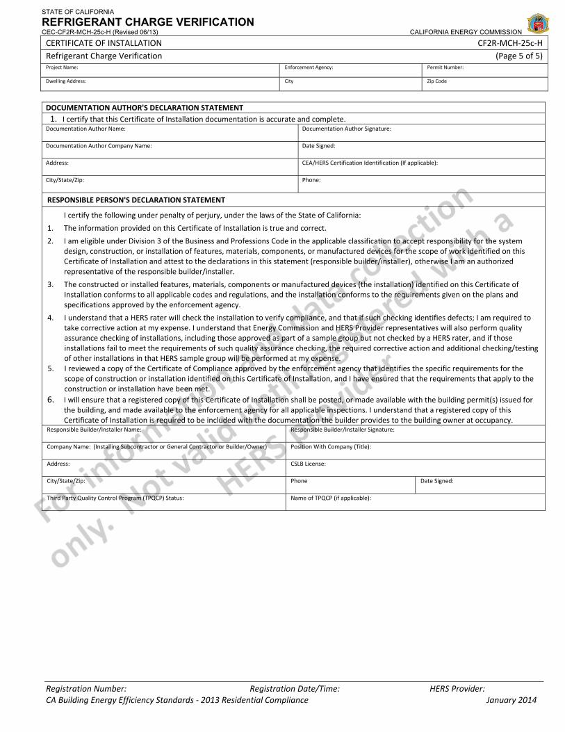
STATE OF CALIFORNIA
REFRIGERANT CHARGE VERIFICATION CEC-CF2R-MCH-25c-H (Revised 06/13) CALIFORNIA ENERGY COMMISSION
CERTIFICATE OF INSTALLATION CF2R‐MCH‐25c‐H Refrigerant Charge Verification (Page 5 of 5) Project Name: Enforcement Agency: Permit Number:
Dwelling Address: City Zip Code
Registration Number: Registration Date/Time: HERS Provider: CA Building Energy Efficiency Standards ‐ 2013 Residential Compliance January 2014
DOCUMENTATION AUTHOR'S DECLARATION STATEMENT1. I certify that this Certificate of Installation documentation is accurate and complete.
Documentation Author Name: Documentation Author Signature:
Documentation Author Company Name: Date Signed:
Address: CEA/HERS Certification Identification (If applicable):
City/State/Zip: Phone:
RESPONSIBLE PERSON'S DECLARATION STATEMENT
I certify the following under penalty of perjury, under the laws of the State of California:
1. The information provided on this Certificate of Installation is true and correct.
2. I am eligible under Division 3 of the Business and Professions Code in the applicable classification to accept responsibility for the system design, construction, or installation of features, materials, components, or manufactured devices for the scope of work identified on this Certificate of Installation and attest to the declarations in this statement (responsible builder/installer), otherwise I am an authorized representative of the responsible builder/installer.
3. The constructed or installed features, materials, components or manufactured devices (the installation) identified on this Certificate of Installation conforms to all applicable codes and regulations, and the installation conforms to the requirements given on the plans and specifications approved by the enforcement agency.
4. I understand that a HERS rater will check the installation to verify compliance, and that if such checking identifies defects; I am required to take corrective action at my expense. I understand that Energy Commission and HERS Provider representatives will also perform quality assurance checking of installations, including those approved as part of a sample group but not checked by a HERS rater, and if those installations fail to meet the requirements of such quality assurance checking, the required corrective action and additional checking/testing of other installations in that HERS sample group will be performed at my expense.
5. I reviewed a copy of the Certificate of Compliance approved by the enforcement agency that identifies the specific requirements for the scope of construction or installation identified on this Certificate of Installation, and I have ensured that the requirements that apply to the construction or installation have been met.
6. I will ensure that a registered copy of this Certificate of Installation shall be posted, or made available with the building permit(s) issued for the building, and made available to the enforcement agency for all applicable inspections. I understand that a registered copy of this Certificate of Installation is required to be included with the documentation the builder provides to the building owner at occupancy.
Responsible Builder/Installer Name: Responsible Builder/Installer Signature:
Company Name: (Installing Subcontractor or General Contractor or Builder/Owner) Position With Company (Title):
Address: CSLB License:
City/State/Zip: Phone Date Signed:
Third Party Quality Control Program (TPQCP) Status: Name of TPQCP (if applicable):
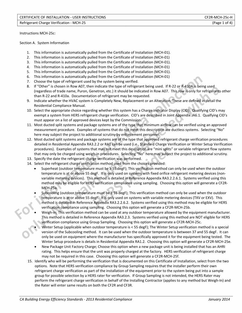
CERTIFICATE OF INSTALLATION ‐ USER INSTRUCTIONS CF2R‐MCH‐25c‐H Refrigerant Charge Verification ‐ MCH‐25 (Page 1 of 4)
CA Building Energy Efficiency Standards ‐ 2013 Residential Compliance January 2014
Instructions MCH‐25c: Section A. System Information
1. This information is automatically pulled from the Certificate of Installation (MCH‐01). 2. This information is automatically pulled from the Certificate of Installation (MCH‐01) 3. This information is automatically pulled from the Certificate of Installation (MCH‐01). 4. This information is automatically pulled from the Certificate of Installation (MCH‐01) 5. This information is automatically pulled from the Certificate of Installation (MCH‐01). 6. This information is automatically pulled from the Certificate of Installation (MCH‐01) 7. Choose the type of refrigerant used by the system being verified. 8. If “Other” is chosen in Row A07, then indicate the type of refrigerant being used. If R‐22 or R‐410A is being used
(regardless of trade name, Puron, Genetron, etc.) it should be indicated in Row A07. This row is only for refrigerants other than R‐22 and R‐410a. Documentation of refrigerant may be requested.
9. Indicate whether the HVAC system is Completely New, Replacement or an Alteration. These are defined in detail the Residential Compliance Manual.
10. Select the appropriate choice regarding whether this system has a Charge Indicator Display (CID). Qualifying CID’s may exempt a system from HERS refrigerant charge verification. CID’s are described in Joint Appendix JA6.1. Qualfying CID’s must appear on a list of approved devices kept by the Commission.
11. Most ducted split systems and package systems are of the type that minimum airflow can be verified using an approved measurement procedure. Examples of systems that do not meet this description are ductless systems. Selecting “No” here may subject the project to additional scrutiny by enforcement personnel.
12. Most ducted split systems and package systems are of the type that approved refrigerant charge verification procedures detailed in Residential Appendix RA3.2.2 or RA1 can be used (i.e., Standard Charge Verification or Winter Setup Verification procedures). Examples of systems that may not meet this description are “mini splits” or variable refrigerant flow systems that may only be charged using weigh‐in procedures. Selecting “No” here may subject the project to additional scrutiny.
13. Specify the date the refrigerant charge verification was performed. 14. Select the refrigerant charge verification method used from the choices provided:
• Superheat (outdoor temperature must be ≥ 55 degF); This verification method can only be used when the outdoor temperature is at or above 55 degF. It is only used on systems with fixed orifice refrigerant metering devices (non‐variable metering devices). This method is detailed in Reference Appendix RA3.2.2.6.1. Systems verified using this method may be eligible for HERS verification compliance using sampling. Choosing this option will generate a CF2R‐MCH‐25a.
• Subcooling (outdoor temperature must be ≥ 55 degF); This verification method can only be used when the outdoor temperature is at or above 55 degF. It is only used on systems with variable metering devices (TXV or EXV). This method is detailed in Reference Appendix RA3.2.2.6.2. Systems verified using this method may be eligible for HERS verification compliance using sampling. Choosing this option will generate a CF2R‐MCH‐25b.
• Weigh‐in; This verification method can be used at any outdoor temperature allowed by the equipment manufacturer. This method is detailed in Reference Appendix RA3.2.3. Systems verified using this method are NOT eligible for HERS verification compliance using Group Sampling. Choosing this option will generate a CF2R‐MCH‐25c.
• Winter Setup (applicable when outdoor temperature is < 55 degF); The Winter Setup verification method is a special version of the Subcooling method. It can be used when the outdoor temperature is between 37 and 55 degF. It can only be used on equipment where the manufacturer has specifically approved it for the equipment being tested. The Winter Setup procedure is details in Residential Appendix RA1.2. Choosing this option will generate a CF2R‐MCH‐25e.
• New Package Unit Factory Charge; Choose this option when a new package unit is being installed that has an AHRI rating. This helps ensure that the unit was properly charged at the factory. HERS verification of refrigerant charge may not be required in this case. Choosing this option will generate a CF2R‐MCH‐25f.
15. Identify who will be performing the verification that is documented on this Certificate of Installation, select from the two options. Note that HERS verification compliance by Group Sampling requires that the installer perform their own refrigerant charge verification as part of the installation of the equipment prior to the system being put into a sample group for possible selection by a HERS rater for verification. If Group Sampling is not intended, the HERS Rater may perform the refrigerant charge verification in behalf of the Installing Contractor (applies to any method but Weigh‐In) and the Rater will enter same results on both the CF2R and CF3R.
CERTIFICATE OF INSTALLATION ‐ USER INSTRUCTIONS CF2R‐MCH‐25c‐H Refrigerant Charge Verification ‐ MCH‐25 (Page 2 of 4)
CA Building Energy Efficiency Standards ‐ 2013 Residential Compliance January 2014
16. The Group Sampling status is automatically displayed based on the input results of Row A14 and Row A15. Group Sampling procedures are detailed Residential Appendix RA2.3.
Section B. Instrument Calibration
1. Enter the date that Digital Refrigerant Scale calibration expires. Digital Refrigerant Scales must be calibrated according to manufacturer’s specifications. This requirement is in Residential Appendix RA3.2.1.4.1. A sticker must be affixed to the scale that shows the calibration check date (expiration date).
2. Enter the date of the most recent Digital Thermocouple Calibration. Specifications for thermocouples and temperature sensors can be found in Residential Appendix RA3.2.2.2.2. Procedures for calibration are detailed in RA3.2.2.4.1. Calibration must happen at least once every 30 days.
3. Digital Refrigerant Scale Calibration status will appear automatically. If the date entered in Row C01 is prior to date of verification this row will indicate that calibration is required and you will not be allowed to continue filling out this document.
4. Digital Thermocouple Calibration status will appear automatically. If the date entered in Row C02 is more than 30 days prior to date of verification this row will indicate that calibration is required and you will not be allowed to continue filling out this document.
Section C. Measurement Access Hole (MAH) Verification Note: if A11=NO, then this table C is not used (system is exempt from MAH requirements)
1. Indicate the method used to demonstrate compliance with the MAH requirement by selecting the appropriate method from the drop down list. Procedures for installing MAH’s are detailed in RA3.2.2.3. Selecting that the MAH cannot be installed consistent with Figure 3.2‐1 may result in additional scrutiny by enforcement personnel.
Section D. Minimum System Airflow Rate Verification Note: if A11=NO, then this table D is not used (system is exempt from Airflow Rate verification requirements)
1. This information is automatically calculated based on the information given in line A09. This is the target minimum system airflow required for the system being verified.
2. This information is automatically calculated based on the MCH‐23which documents the measured airflow of the system being verified. If the measured airflow is not adequate it will not comply with the airflow requirements and refrigerant charge verification cannot be performed.
Section E. Weigh In Charge Procedure
1. Measure and record the outside air dry‐bulb temperature in degrees F. This will affect the procedures that may be used for HERS verification.
2. Specify the method of weigh‐in. There are two options that may be used. One is to add or remove a small, weighed portion of refrigerant from a factory charged unit (Charge Adjustment). The other is to weigh the entire charge of refrigerant before introducing it into the system (Total Charge). Select either one. Note: The amount of refrigerant in systems that are not newly installed cannot be assumed to be the factory charge. Systems using existing refrigerant must use the Total Charge method. Only new, factory installed equipment can utilize the Charge Adjustment method.
3. Enter the Manufacturer’s Standard Charge for condenser in pounds and ounces. This is the amount of refrigerant that the manufacturer specifies for a “standard” installation (typical coil match, typical line set size and length). For the Charge Adjustment method, this is the amount of refrigerant that factory charges the system to. Be prepared to provide manufacturer’s documentation to support this value.
4. The Manufacturer’s Standard Charge, specified in E03 is based on a standard liquid line length, typically 25 feet. Enter the value here, in feet. Be prepared to provide manufacturer’s documentation to support this value.
5. The Manufacturer’s Standard Charge, specified in E03 is based on a standard liquid line diameter. Enter the value here, in inches (for example: 1/4”, 3/8”, etc.). Be prepared to provide manufacturer’s documentation to support this value.
6. The Manufacturer’s Standard Charge, specified in E03 is based on a standard indoor (evaporator) coil size. Enter the value here, in tons. Be prepared to provide manufacturer’s documentation to support this value.
CERTIFICATE OF INSTALLATION ‐ USER INSTRUCTIONS CF2R‐MCH‐25c‐H Refrigerant Charge Verification ‐ MCH‐25 (Page 3 of 4)
CA Building Energy Efficiency Standards ‐ 2013 Residential Compliance January 2014
7. Enter the length of the liquid line installed on the system being verified, in feet. This value must be compared to the standard liquid line length entered in E04 and used to determine if the Manufacturer’s Standard Charge entered in E03 is appropriate.
8. Enter the diameter of the liquid line installed on the system being verified, in inches (for example: 1/4”, 3/8”, etc.). This value must be compared to the standard liquid line diameter entered in E05 and used to determine if the Manufacturer’s Standard Charge entered in E03 is appropriate.
9. Enter the size of the indoor (evaporator) coil installed on the system being verified, in tons. This value must be compared to the standard coil size entered in E06 and used to determine if the Manufacturer’s Standard Charge entered in E03 is appropriate.
10. Enter the Charge Adjustment to Standard Charge, in ounces. This is the amount of refrigerant that the manufacturer specifies to add to, or remove from, the Manufacturer’s Standard Charge entered in E03. This value must come from manufacturer’s specifications using the standard values entered in Rows E04 through E06 to the installed values entered in Rows E07 through E09. If refrigerant is to be added, this value should be a positive number. If refrigerant is to be removed, this value should be a negative number. Be prepared to provide manufacturer’s documentation to support this value.
11. This value is calculated automatically. If “Charge Adjustment” was specified in Row E02, then the value shown here will be the same as the value shown in Row E10. This is the amount of weighed refrigerant that will be added or removed from the factory charged unit. If refrigerant is to be added, this value should be a positive number. If refrigerant is to be removed, this value should be a negative number. If “Total Charge” was specified in Row E02, then the value shown here will be the value in row E03 added to the value in row E10. This is the total amount of refrigerant that will be in the system, all of which must be weighed before introducing into the system.
12. Enter the amount of refrigerant weighed and added to, or removed from, system. If refrigerant is to be added, this value should be a positive number. If refrigerant is to be removed from a factory charged system, this value should be a negative number. This value must match the value in E11 for the system to pass.
13. If the value in line E11 equals the value in line E12, a statement will appear here indicating that the system passes the weigh‐in method. Otherwise, a statement will appear here indicating that the system does not pass.
Section F. Weigh In Charge Verification – Additional Requirements
1. Additional requirements are items that must be done, but are not specifically required to be checked by the HERS rater. By signing the Declaration Statement on this document, the installer is declaring that all of these additional requirements have been met. The requirement for brazing lines charged with dry nitrogen is specified in Residential Appendix RA3.2.3.1.5.
2. Additional requirements are items that must be done, but are not specifically required to be checked by the HERS rater. By signing the Declaration Statement on this document, the installer is declaring that all of these additional requirements have been met. The requirement for checking refrigerant lines for leaks by evacuating to 500 microns or less and rising by no more than 300 microns after 5 minutes is specified in Residential Appendix RA3.2.3.1.5.
Section G. Verification of Charge Indicator Display
1. Enter the manufacturer name or make of the approved Charge Indicator Display. Must match name shown on the list of approved devices kept by the Commission.
2. Enter the manufacturer model number of the approved Charge Indicator Display. Must match name shown on the list of approved devices kept by the Commission.
3. The installer must confirm that the CID display module is mounted adjacent to thermostat that controls the system being verified. This requirement is detailed in Residential Appendix RA3.4.2.
4. The installer must confirm that the installed CID is approved and appears the list of approved devices kept by the Commission. This requirement is detailed in Residential Appendix RA3.4.2.
5. The installer must confirm that the system has operated for at least 15 minutes and that they system is operating within acceptable parameters as specified by the CID and equipment manufacturers. This requirement is detailed in Residential Appendix RA3.4.2.
Section H. Indicator Display – Additional Requirements

CERTIFICATE OF INSTALLATION ‐ USER INSTRUCTIONS CF2R‐MCH‐25c‐H Refrigerant Charge Verification ‐ MCH‐25 (Page 4 of 4)
CA Building Energy Efficiency Standards ‐ 2013 Residential Compliance January 2014
1. Additional requirements are items that must be done, but are not specifically required to be checked by the HERS rater. By signing the Declaration Statement on this document, the installer is declaring that all of these additional requirements have been met. The requirement for installing CIDs to manufacturer’s specifications (unless factory installed) can be found in Joint Appendix JA6.1.3.
2. Additional requirements are items that must be done, but are not specifically required to be checked by the HERS rater. By signing the Declaration Statement on this document, the installer is declaring that all of these additional requirements have been met. The requirement for providing manufacturer’s instructions and other documentation for CIDs can be found in Joint Appendix JA6.1.4.
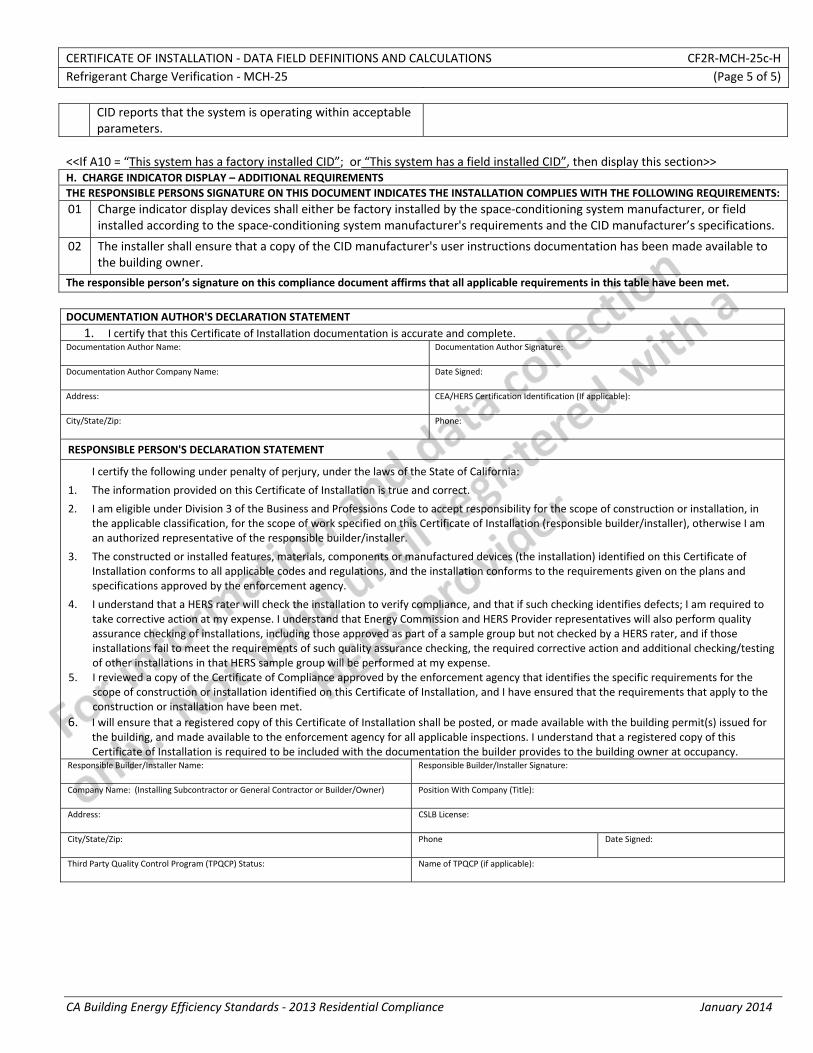
CERTIFICATE OF INSTALLATION ‐ DATA FIELD DEFINITIONS AND CALCULATIONS CF2R‐MCH‐25c‐H Refrigerant Charge Verification ‐ MCH‐25 (Page 5 of 5)
CA Building Energy Efficiency Standards ‐ 2013 Residential Compliance January 2014
CID reports that the system is operating within acceptable parameters.
<<If A10 = “This system has a factory installed CID”; or “This system has a field installed CID”, then display this section>> H. CHARGE INDICATOR DISPLAY – ADDITIONAL REQUIREMENTS THE RESPONSIBLE PERSONS SIGNATURE ON THIS DOCUMENT INDICATES THE INSTALLATION COMPLIES WITH THE FOLLOWING REQUIREMENTS: 01 Charge indicator display devices shall either be factory installed by the space‐conditioning system manufacturer, or field
installed according to the space‐conditioning system manufacturer's requirements and the CID manufacturer’s specifications.
02 The installer shall ensure that a copy of the CID manufacturer's user instructions documentation has been made available to the building owner.
The responsible person’s signature on this compliance document affirms that all applicable requirements in this table have been met.
DOCUMENTATION AUTHOR'S DECLARATION STATEMENT
1. I certify that this Certificate of Installation documentation is accurate and complete. Documentation Author Name: Documentation Author Signature:
Documentation Author Company Name: Date Signed:
Address: CEA/HERS Certification Identification (If applicable):
City/State/Zip: Phone:
RESPONSIBLE PERSON'S DECLARATION STATEMENT
I certify the following under penalty of perjury, under the laws of the State of California:
1. The information provided on this Certificate of Installation is true and correct.
2. I am eligible under Division 3 of the Business and Professions Code to accept responsibility for the scope of construction or installation, in the applicable classification, for the scope of work specified on this Certificate of Installation (responsible builder/installer), otherwise I am an authorized representative of the responsible builder/installer.
3. The constructed or installed features, materials, components or manufactured devices (the installation) identified on this Certificate of Installation conforms to all applicable codes and regulations, and the installation conforms to the requirements given on the plans and specifications approved by the enforcement agency.
4. I understand that a HERS rater will check the installation to verify compliance, and that if such checking identifies defects; I am required to take corrective action at my expense. I understand that Energy Commission and HERS Provider representatives will also perform quality assurance checking of installations, including those approved as part of a sample group but not checked by a HERS rater, and if those installations fail to meet the requirements of such quality assurance checking, the required corrective action and additional checking/testing of other installations in that HERS sample group will be performed at my expense.
5. I reviewed a copy of the Certificate of Compliance approved by the enforcement agency that identifies the specific requirements for the scope of construction or installation identified on this Certificate of Installation, and I have ensured that the requirements that apply to the construction or installation have been met.
6. I will ensure that a registered copy of this Certificate of Installation shall be posted, or made available with the building permit(s) issued for the building, and made available to the enforcement agency for all applicable inspections. I understand that a registered copy of this Certificate of Installation is required to be included with the documentation the builder provides to the building owner at occupancy.
Responsible Builder/Installer Name: Responsible Builder/Installer Signature:
Company Name: (Installing Subcontractor or General Contractor or Builder/Owner) Position With Company (Title):
Address: CSLB License:
City/State/Zip: Phone Date Signed:
Third Party Quality Control Program (TPQCP) Status: Name of TPQCP (if applicable):
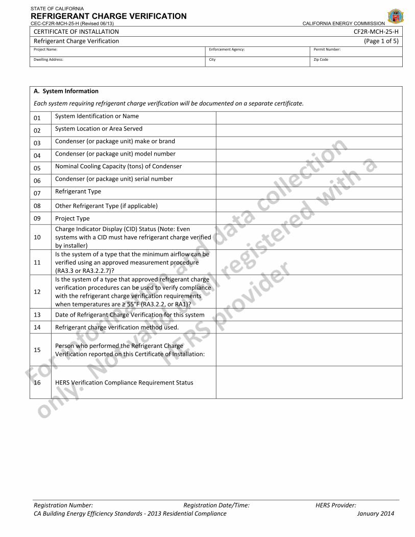
STATE OF CALIFORNIA
REFRIGERANT CHARGE VERIFICATION CEC-CF2R-MCH-25-H (Revised 06/13) CALIFORNIA ENERGY COMMISSION
CERTIFICATE OF INSTALLATION CF2R‐MCH‐25‐H Refrigerant Charge Verification (Page 1 of 5) Project Name: Enforcement Agency: Permit Number:
Dwelling Address: City Zip Code
Registration Number: Registration Date/Time: HERS Provider: CA Building Energy Efficiency Standards ‐ 2013 Residential Compliance January 2014
A. System Information
Each system requiring refrigerant charge verification will be documented on a separate certificate.
01 System Identification or Name
02 System Location or Area Served
03 Condenser (or package unit) make or brand
04 Condenser (or package unit) model number
05 Nominal Cooling Capacity (tons) of Condenser
06 Condenser (or package unit) serial number
07 Refrigerant Type
08 Other Refrigerant Type (if applicable)
09 Project Type
10 Charge Indicator Display (CID) Status (Note: Even systems with a CID must have refrigerant charge verified by installer)
11 Is the system of a type that the minimum airflow can be verified using an approved measurement procedure (RA3.3 or RA3.2.2.7)?
12
Is the system of a type that approved refrigerant charge verification procedures can be used to verify compliance with the refrigerant charge verification requirements when temperatures are ≥ 55°F (RA3.2.2, or RA1)?
13 Date of Refrigerant Charge Verification for this system
14 Refrigerant charge verification method used.
15 Person who performed the Refrigerant Charge Verification reported on this Certificate of Installation:
16 HERS Verification Compliance Requirement Status
STATE OF CALIFORNIA
REFRIGERANT CHARGE VERIFICATION CEC-CF2R-MCH-25-H (Revised 06/13) CALIFORNIA ENERGY COMMISSION
CERTIFICATE OF INSTALLATION CF2R‐MCH‐25‐H Refrigerant Charge Verification (Page 2 of 5) Project Name: Enforcement Agency: Permit Number:
Dwelling Address: City Zip Code
Registration Number: Registration Date/Time: HERS Provider: CA Building Energy Efficiency Standards ‐ 2013 Residential Compliance January 2014
Winter Setup Charge Verification Procedure ‐ MCH25e
• Winter Setup for the Standard Charge Verification Procedure is specified in Reference Residential Appendix RA1.2.
• Procedures for determining Refrigerant Charge using the Standard Charge Verification Procedure are given in Reference Residential Appendix RA3.2.2.
B. System Model Applicability for Winter Setup Method
01 Refrigerant metering device
02 Winter Setup Method applicability status
03 The responsible person's signature on this document indicates confirmation that the installed model number is currently listed as approved for Winter Setup Method on the Energy Commission website:
http://www.energy.ca.gov/title24/2008standards/special_case_appliance/ C. Instrument Calibration Instrumentation specifications and procedures for instrument calibration are given in Reference Residential Appendix RA3.2.2.2 and RA3.2.2.4. respectively.
01 Date of Digital Refrigerant Gauge Calibration
02 Date of Digital Thermocouple Calibration
03 Digital Refrigerant Gauge Calibration Status
04 Digital Thermocouple Calibration Status
D. Measurement Access Hole (MAH) VerificationProcedures for installing MAH are specified in Reference Residential Appendix RA3.2.2.3
01 Method used to demonstrate compliance with the Measurement Access Hole (MAH) requirement
E. Minimum System Airflow Rate Verification Procedures for verifying minimum system airflow are specified in Reference Residential Appendix RA3.2.2.7.
01 Minimum Required System Airflow Rate (cfm)
02 System Airflow Rate Verification Status
STATE OF CALIFORNIA
REFRIGERANT CHARGE VERIFICATION CEC-CF2R-MCH-25-H (Revised 06/13) CALIFORNIA ENERGY COMMISSION
CERTIFICATE OF INSTALLATION CF2R‐MCH‐25‐H Refrigerant Charge Verification (Page 3 of 5) Project Name: Enforcement Agency: Permit Number:
Dwelling Address: City Zip Code
Registration Number: Registration Date/Time: HERS Provider: CA Building Energy Efficiency Standards ‐ 2013 Residential Compliance January 2014
F. Data Collection and Calculations
Procedures for data collection and variable metering device calculations are given in Reference Residential Appendix RA3.2.2.5 and RA3.2.2.6.2 respectively.
01
The responsible person's signature on this document indicates confirmation that, with a Condenser Outlet Air Restrictor installed, and after system operation was stabilized for at least 15 minutes, throughout the data collection for this verification, the difference between the liquid line pressure and suction line pressure was maintained between 160 and 220 psi for R‐410A systems, or between 100 and 145 psi for R‐22 systems.
02 Lowest return air dry bulb temperature that occurred during the refrigerant charge verification procedure (degreeF)
03 Measured Condenser air entering dry‐bulb temperature (T condenser, db) (degreeF)
04 Outdoor Temperature Qualification Status
05 Measured Liquid Line Temperature (Tliquid) (degreeF)
06 Measured Liquid Line Pressure (Pliquid) (pisg)
07 Condenser saturation temperature (Tcondensor, sat) from digital gauge or P‐T Table using Line F06 (degree F)
08 Measured Subcool (Line F07 – Line F05) (degree F)
09 Target Subcool from Manufacturer (degree F)
10 Compliance Statement:
G. Metering Device Verification Procedures for the verification of proper metering device operation are specified in RA3.2.2.5.2
01 Measured Suction line temperature (Tsuction) (degreeF)
02 Measured Suction line pressure (Psuction) (psig)
03 Evaporator saturation temperature (Tevaporator, sat) from digital gauge or P‐T Table using line G02 (degreeF)
04 Measured Superheat (Line G01 – Line G03) (degreeF)
05 Measured Superheat (Line G04) is between 4 and 25 deg F (inclusive)
06 Measured Superheat (Line G04) is within manufacturer’s specifications, if known.
07 Compliance Statement:
STATE OF CALIFORNIA
REFRIGERANT CHARGE VERIFICATION CEC-CF2R-MCH-25-H (Revised 06/13) CALIFORNIA ENERGY COMMISSION
CERTIFICATE OF INSTALLATION CF2R‐MCH‐25‐H Refrigerant Charge Verification (Page 4 of 5) Project Name: Enforcement Agency: Permit Number:
Dwelling Address: City Zip Code
Registration Number: Registration Date/Time: HERS Provider: CA Building Energy Efficiency Standards ‐ 2013 Residential Compliance January 2014
H. Confirmation of Refrigerant Pressure Differential
Procedures for the Winter Setup are detailed in RA1.2.22
01 Phigh, – Plow (psi) from F06 and G02
02 Compliance Statement: If A10 = “This system has a factory installed CID”; or “This system has a field installed CID”, then use this section I. Charge Indicator Display
Procedures for the Charge Indicator Display Verification are detailed in RA3.4.2
01 CID Manufacturer Name/Make
02 CID Model Number
03 The display module is mounted adjacent to the system thermostat
04
The manufacturer has certified to the Energy Commission that the CID model meets the requirements of Reference Joint Appendix JA6 (Make and model found on CEC list of approved CID devices)
05 The system has operated for at least 15 minutes and the CID reports that the system is operating within acceptable parameters.
STATE OF CALIFORNIA
REFRIGERANT CHARGE VERIFICATION CEC-CF2R-MCH-25-H (Revised 06/13) CALIFORNIA ENERGY COMMISSION
CERTIFICATE OF INSTALLATION CF2R‐MCH‐25‐H Refrigerant Charge Verification (Page 5 of 5) Project Name: Enforcement Agency: Permit Number:
Dwelling Address: City Zip Code
Registration Number: Registration Date/Time: HERS Provider: CA Building Energy Efficiency Standards ‐ 2013 Residential Compliance January 2014
If A10 = “This system has a factory installed CID”; or “This system has a field installed CID”, then this section is applicable J. CHARGE INDICATOR DISPLAY – ADDITIONAL REQUIREMENTS THE RESPONSIBLE PERSONS SIGNATURE ON THIS DOCUMENT INDICATES THE INSTALLATION COMPLIES WITH THE FOLLOWING REQUIREMENTS:
01 Charge indicator display devices shall either be factory installed by the space‐conditioning system manufacturer, or field installed according to the space‐conditioning system manufacturer's requirements and the CID manufacturer’s specifications.
02 The installer shall ensure that a copy of the CID manufacturer's user instructions documentation has been made available to the building owner.
DOCUMENTATION AUTHOR'S DECLARATION STATEMENT1. I certify that this Certificate of Installation documentation is accurate and complete.
Documentation Author Name: Documentation Author Signature:
Documentation Author Company Name: Date Signed:
Address: CEA/HERS Certification Identification (If applicable):
City/State/Zip: Phone:
RESPONSIBLE PERSON'S DECLARATION STATEMENT
I certify the following under penalty of perjury, under the laws of the State of California:
1. The information provided on this Certificate of Installation is true and correct.
2. I am eligible under Division 3 of the Business and Professions Code in the applicable classification to accept responsibility for the system design, construction, or installation of features, materials, components, or manufactured devices for the scope of work identified on this Certificate of Installation and attest to the declarations in this statement (responsible builder/installer), otherwise I am an authorized representative of the responsible builder/installer.
3. The constructed or installed features, materials, components or manufactured devices (the installation) identified on this Certificate of Installation conforms to all applicable codes and regulations, and the installation conforms to the requirements given on the plans and specifications approved by the enforcement agency.
4. I understand that a HERS rater will check the installation to verify compliance, and that if such checking identifies defects; I am required to take corrective action at my expense. I understand that Energy Commission and HERS Provider representatives will also perform quality assurance checking of installations, including those approved as part of a sample group but not checked by a HERS rater, and if those installations fail to meet the requirements of such quality assurance checking, the required corrective action and additional checking/testing of other installations in that HERS sample group will be performed at my expense.
5. I reviewed a copy of the Certificate of Compliance approved by the enforcement agency that identifies the specific requirements for the scope of construction or installation identified on this Certificate of Installation, and I have ensured that the requirements that apply to the construction or installation have been met.
6. I will ensure that a registered copy of this Certificate of Installation shall be posted, or made available with the building permit(s) issued for the building, and made available to the enforcement agency for all applicable inspections. I understand that a registered copy of this Certificate of Installation is required to be included with the documentation the builder provides to the building owner at occupancy.
Responsible Builder/Installer Name: Responsible Builder/Installer Signature:
Company Name: (Installing Subcontractor or General Contractor or Builder/Owner) Position With Company (Title):
Address: CSLB License:
City/State/Zip: Phone Date Signed:
Third Party Quality Control Program (TPQCP) Status: Name of TPQCP (if applicable):
CERTIFICATE OF INSTALLATION – USER INSTRUCTIONS CF2R‐MCH‐25‐H Refrigerant Charge Verification ‐ MCH‐25e (Page 1 of 5)
CA Building Energy Efficiency Standards ‐ 2013 Residential Compliance January 2014
Instructions MCH‐25e: Section A. System Information
1. This information is automatically pulled from the Certificate of Installation (MCH‐01). 2. This information is automatically pulled from the Certificate of Installation (MCH‐01) 3. This information is automatically pulled from the Certificate of Installation (MCH‐01). 4. This information is automatically pulled from the Certificate of Installation (MCH‐01) 5. This information is automatically pulled from the Certificate of Installation (MCH‐01). 6. This information is automatically pulled from the Certificate of Installation (MCH‐01) 7. Choose the type of refrigerant used by the system being verified. 8. If “Other” is chosen in Row A07, then indicate the type of refrigerant being used. If R‐22 or R‐410A is
being used (regardless of trade name, Puron, Genetron, etc.) it should be indicated in Row A07. This row is only for refrigerants other than R‐22 and R‐410a. Documentation of refrigerant may be requested.
9. Indicate whether the HVAC system is Completely New, Replacement or an Alteration. These are defined in detail the Residential Compliance Manual.
10. Select the appropriate choice regarding whether this system has a Charge Indicator Display (CID). Qualifying CID’s may exempt a system from HERS refrigerant charge verification. CID’s are described in Joint Appendix JA6.1. Qualifying CID’s must appear on a list of approved devices kept by the Commission.
11. Most ducted split systems and package systems are of the type that minimum airflow can be verified using an approved measurement procedure. Examples of systems that do not meet this description are ductless systems. Selecting “No” here may subject the project to additional scrutiny by enforcement personnel.
12. Most ducted split systems and package systems are of the type that approved refrigerant charge verification procedures detailed in Residential Appendix RA3.2.2 or RA1 can be used (i.e., Standard Charge Verification or Winter Setup Verification procedures). Examples of systems that may not meet this description are “mini splits” or variable refrigerant flow systems that may only be charged using weigh‐in procedures. Selecting “No” here may subject the project to additional scrutiny.
13. Specify the date the refrigerant charge verification was performed. 14. Select the refrigerant charge verification method used from the choices provided:
• Superheat (outdoor temperature must be ≥ 55 degF); This verification method can only be used when the outdoor temperature is at or above 55 degF. It is only used on systems with fixed orifice refrigerant metering devices (non‐variable metering devices). This method is detailed in Reference Appendix RA3.2.2.6.1. Systems verified using this method may be eligible for HERS verification compliance using sampling. Choosing this option will generate a CF2R‐MCH‐25a.
• Subcooling (outdoor temperature must be ≥ 55 degF); This verification method can only be used when the outdoor temperature is at or above 55 degF. It is only used on systems with variable metering devices (TXV or EXV). This method is detailed in Reference Appendix RA3.2.2.6.2. Systems verified using this method may be eligible for HERS verification compliance using sampling. Choosing this option will generate a CF2R‐MCH‐25b.
• Weigh‐in; This verification method can be used at any outdoor temperature allowed by the equipment manufacturer. This method is detailed in Reference Appendix RA3.2.3. Systems
CERTIFICATE OF INSTALLATION – USER INSTRUCTIONS CF2R‐MCH‐25‐H Refrigerant Charge Verification ‐ MCH‐25e (Page 2 of 5)
CA Building Energy Efficiency Standards ‐ 2013 Residential Compliance January 2014
verified using this method are NOT eligible for HERS verification compliance using Group Sampling. Choosing this option will generate a CF2R‐MCH‐25c.
• Winter Setup (applicable when outdoor temperature is < 55 degF); The Winter Setup verification method is a special version of the Subcooling method. It can be used when the outdoor temperature is between 37 and 55 degF. It can only be used on equipment where the manufacturer has specifically approved it for the equipment being tested. The Winter Setup procedure is details in Residential Appendix RA1.2. Choosing this option will generate a CF2R‐MCH‐25e.
• New Package Unit Factory Charge; Choose this option when a new package unit is being installed that has an AHRI rating. This helps ensure that the unit was properly charged at the factory. HERS verification of refrigerant charge may not be required in this case. Choosing this option will generate a CF2R‐MCH‐25f.
15. Identify who will be performing the verification that is documented on this Certificate of Installation, select from the two options. Note that HERS verification compliance by Group Sampling requires that the installer perform their own refrigerant charge verification as part of the installation of the equipment prior to the system being put into a sample group for possible selection by a HERS rater for verification. If Group Sampling is not intended, the HERS Rater may perform the refrigerant charge verification in behalf of the Installing Contractor (applies to any method but Weigh‐In) and the Rater will enter same results on both the CF2R and CF3R.
16. The Group Sampling status is automatically displayed based on the input results of Row A14 and Row A15. Group Sampling procedures are detailed Residential Appendix RA2.3.
Section B. System Model Applicability for Winter Setup Method
1. Select the correct metering device used on the system being verified. This will check against the refrigerant charge verification method selected in Row A14. An error message will appear in Row B02 if the wrong verification method may has been selected. The Winter Setup Method can only be used on systems with variable metering devices (TXV or EXV).
2. An error message in here indicates that the wrong verification method may have been selected. The Winter Setup Method can only be used on systems with variable metering devices (TXV or EXV).
3. Winter Setup Method shall only be used on system model numbers that have a TXV or EXV, and for which the manufacturer has provided written approval to the energy Commission indicating that the Winter Setup Method may be used to verify refrigerant charge. The list of approved systems can be found at the web address shown on the form. The installer must confirm that the model number for the equipment being verified appears on this list.
Section C. Instrument Calibration
1. Enter the date of most recent Digital Refrigerant Gauge Calibration Field Check. Analog gauges are not allowed for verification purposes under the 2013 Standards. Specification for pressure gauges is found in Residential Appendix RA3.2.2.2.3. Procedures for the field check procedure are detailed in RA3.2.2.4.2. Calibration field check must happen at least once every 30 days.
2. Enter the date of the most recent Digital Thermocouple Calibration. Specifications for thermocouples and temperature sensors can be found in Residential Appendix RA3.2.2.2.2. Procedures for calibration are detailed in RA3.2.2.4.1. Calibration must happen at least once every 30 days.

CERTIFICATE OF INSTALLATION – USER INSTRUCTIONS CF2R‐MCH‐25‐H Refrigerant Charge Verification ‐ MCH‐25e (Page 3 of 5)
CA Building Energy Efficiency Standards ‐ 2013 Residential Compliance January 2014
3. Digital Refrigerant Gauge Calibration status will appear automatically. If the date entered in Row C01 is more than 30 days prior to date of verification this row will indicate that calibration is required and you will not be allowed to continue filling out this document.
4. Digital Thermocouple Calibration status will appear automatically. If the date entered in Row C02 is more than 30 days prior to date of verification this row will indicate that calibration is required and you will not be allowed to continue filling out this document.
Section D. Measurement Access Hole (MAH) Verification
1. Indicate the method used to demonstrate compliance with the MAH requirement by selecting the appropriate method from the drop down list. Procedures for installing MAH’s are detailed in RA3.2.2.3. Selecting that the MAH cannot be installed consistent with Figure 3.2‐1 may result in additional scrutiny by enforcement personnel.
Section E. Minimum System Airflow Rate Verification
1. This information is automatically calculated based on the information given in line A09. This is the target minimum system airflow required for the system being verified.
2. This information is automatically calculated based on the MCH‐23 which documents the measured airflow of the system being verified. If the measured airflow is not adequate it will not comply with the airflow requirements and refrigerant charge verification cannot be performed.
Section F. Winter Setup Method – Data Collection and Calculations
1. The Winter Setup Method is a variation on the Subcooling Method and involves using a Condenser Outlet Restrictor to drive up the refrigerant pressures. The procedures for this are detailed in Residential Appendix RA1.2.2
2. Measure and record the lowest return air dry‐bulb temperature that occurred during the refrigerant charge procedure, in degrees F. This temperature must remain above 70 degF during the verification procedure. This requirement is detailed in Residential Appendix RA3.2.2.5.
3. Measure and record the condenser air dry‐bulb temperature (Tcondenser) in degrees F. This value must be at least 37 degF and no more than 115 degF to use the Subcooling Charge Verification Method.
4. If a value less than 37 degF or greater than 115 degF is entered in Row F03 the Subcooling Method cannot be used.
5. Measure and record the liquid line temperature (Tliquid) in degrees F. This procedure is detailed in RA3.2.2.5. This value is used to calculate the measured subcool temperature.
6. Measure and record the liquid line pressure (Pliquid) in psig. This procedure is detailed in RA3.2.2.5. This value is used to determine the condenser saturation temperature (Tcondenser,sat) from a pressure temperature chart for the appropriate refrigerant (can be internal to a digital gauge), which is entered into Row F07.
7. Enter the condenser saturation temperature (Tcondenser,sat) from the digital gauge or a separate pressure‐temperature chart that corresponds to the liquid line pressure entered in Row F06, in degrees F.
CERTIFICATE OF INSTALLATION – USER INSTRUCTIONS CF2R‐MCH‐25‐H Refrigerant Charge Verification ‐ MCH‐25e (Page 4 of 5)
CA Building Energy Efficiency Standards ‐ 2013 Residential Compliance January 2014
8. Measured Subcooling is automatically calculated as the difference between the liquid line temperature (Row F05) and the condenser saturation temperature (Row F07)
9. Enter target subcooling from manufacturer. This may be a challenge to find for older equipment. Internet searches can sometimes result in archived equipment specifications for the equipment in question, or sometimes a very similar model. If the manufacturer’s target cannot be found the Commission’s Executive Director may provide additional guidance for compliance.
10. System passes Subcooling Method when Row F09 is within plus or minus 5 degrees of Row F08. Section G. Metering Device Verification
1. Measure and record the suction line temperature (Tsuction) in degrees F. This procedure is detailed in RA3.2.2.5. This value is used to calculate the measured superheat.
2. Measure and record the suction line pressure (Psuction) in psig. This procedure is detailed in RA3.2.2.5. This value is used to determine the evaporator saturation temperature (Tevaporator,sat) from a pressure temperature chart for the appropriate refrigerant (can be internal to a digital gauge), which is entered into Row G03.
3. Enter the evaporator saturation temperature (Tevaporator,sat) from the digital gauge or a separate pressure‐temperature chart that corresponds to the suction line pressure entered in Row G02, in degrees F.
4. Measured superheat is automatically calculated as the difference between the suction line temperature (Row G01) and the evaporator saturation temperature (Row G03)
5. There are two possible criteria for passing. If the manufacturer’s specification is known it should be used, otherwise the CEC requirement is that the superheat be between 4 and 25 degF, inclusive. This row checks the CEC requirement.
6. If the manufacturer’s target superheat for ensuring proper metering device operation is known, it supersedes the CEC requirement of being between 4 and 25 degF. If “Yes, documentation to be provided upon request.” is selected, the installer should be prepared to provide documentation for the target values used.
7. There are two possible criteria for passing. If the manufacturer’s specification is known it should be used, otherwise the CEC requirement is that the superheat be between 4 and 25 degF, inclusive. If “Yes, documentation to be provided upon request.” is selected in Row G06, the installer should be prepared to provide documentation for the target values used.
Section H. Confirmation of Refrigerant Pressure Differential
1. This field is automatically calculated base on the liquid line (high side) pressure and suction line (low side) pressure values previously entered. The protocols for the Winter Setup Method require that this pressure differential be between 160 psig and 220 psig, inclusive, for R‐410a refrigerant; and between 100 psig and 145 psig, inclusive, for R‐22 refrigerant. These procedures are detailed in Residential Appendix RA1.2.2.
2. This field is automatically calculated base on the liquid line (high side) pressure and suction line (low side) pressure values previously entered. The protocols for the Winter Setup Method require that this pressure differential be between 160 psig and 220 psig, inclusive, for R‐410a refrigerant; and between 100 psig and 145 psig, inclusive, for R‐22 refrigerant. These procedures are detailed in Residential Appendix RA1.2.2. If the pressure differential is not within the correct range, a statement will appear
CERTIFICATE OF INSTALLATION – USER INSTRUCTIONS CF2R‐MCH‐25‐H Refrigerant Charge Verification ‐ MCH‐25e (Page 5 of 5)
CA Building Energy Efficiency Standards ‐ 2013 Residential Compliance January 2014
here that the system does not comply and the test will need to be redone using the appropriate procedures.
Section I. Verification of Charge Indicator Display
1. Enter the manufacturer name or make of the approved Charge Indicator Display. Must match name shown on the list of approved devices kept by the Commission.
2. Enter the manufacturer model number of the approved Charge Indicator Display. Must match name shown on the list of approved devices kept by the Commission.
3. The installer must confirm that the CID display module is mounted adjacent to thermostat that controls the system being verified. This requirement is detailed in Residential Appendix RA3.4.2.
4. The installer must confirm that the installed CID is approved and appears the list of approved devices kept by the Commission. This requirement is detailed in Residential Appendix RA3.4.2.
5. The installer must confirm that the system has operated for at least 15 minutes and that they system is operating within acceptable parameters as specified by the CID and equipment manufacturers. This requirement is detailed in Residential Appendix RA3.4.2.
CERTIFICATE OF INSTALLATION – DATA FIELD DEFINITIONS AND CALCULATIONS CF2R‐MCH‐25‐H Refrigerant Charge Verification ‐ MCH‐25e (Page 7 of 7)
CA Building Energy Efficiency Standards ‐ 2013 Residential Compliance January 2014
<<If A10 = “This system has a factory installed CID”; or “This system has a field installed CID”, then display this section>> J. CHARGE INDICATOR DISPLAY – ADDITIONAL REQUIREMENTS THE RESPONSIBLE PERSONS SIGNATURE ON THIS DOCUMENT INDICATES THE INSTALLATION COMPLIES WITH THE FOLLOWING REQUIREMENTS:
01 Charge indicator display devices shall either be factory installed by the space‐conditioning system manufacturer, or field installed according to the space‐conditioning system manufacturer's requirements and the CID manufacturer’s specifications.
02 The installer shall ensure that a copy of the CID manufacturer's user instructions documentation has been made available to the building owner.
DOCUMENTATION AUTHOR'S DECLARATION STATEMENT2. I certify that this Certificate of Installation documentation is accurate and complete.
Documentation Author Name: Documentation Author Signature:
Documentation Author Company Name: Date Signed:
Address: CEA/HERS Certification Identification (If applicable):
City/State/Zip: Phone:
RESPONSIBLE PERSON'S DECLARATION STATEMENT
I certify the following under penalty of perjury, under the laws of the State of California:
7. The information provided on this Certificate of Installation is true and correct.
8. I am eligible under Division 3 of the Business and Professions Code to accept responsibility for the scope of construction or installation, in the applicable classification, for the scope of work specified on this Certificate of Installation (responsible builder/installer), otherwise I am an authorized representative of the responsible builder/installer.
9. The constructed or installed features, materials, components or manufactured devices (the installation) identified on this Certificate of Installation conforms to all applicable codes and regulations, and the installation conforms to the requirements given on the plans and specifications approved by the enforcement agency.
10. I understand that a HERS rater will check the installation to verify compliance, and that if such checking identifies defects; I am required to take corrective action at my expense. I understand that Energy Commission and HERS Provider representatives will also perform quality assurance checking of installations, including those approved as part of a sample group but not checked by a HERS rater, and if those installations fail to meet the requirements of such quality assurance checking, the required corrective action and additional checking/testing of other installations in that HERS sample group will be performed at my expense.
11. I reviewed a copy of the Certificate of Compliance approved by the enforcement agency that identifies the specific requirements for the scope of construction or installation identified on this Certificate of Installation, and I have ensured that the requirements that apply to the construction or installation have been met.
12. I will ensure that a registered copy of this Certificate of Installation shall be posted, or made available with the building permit(s) issued for the building, and made available to the enforcement agency for all applicable inspections. I understand that a registered copy of this Certificate of Installation is required to be included with the documentation the builder provides to the building owner at occupancy.
Responsible Builder/Installer Name: Responsible Builder/Installer Signature:
Company Name: (Installing Subcontractor or General Contractor or Builder/Owner) Position With Company (Title):
Address: CSLB License:
City/State/Zip: Phone Date Signed:
Third Party Quality Control Program (TPQCP) Status: Name of TPQCP (if applicable):
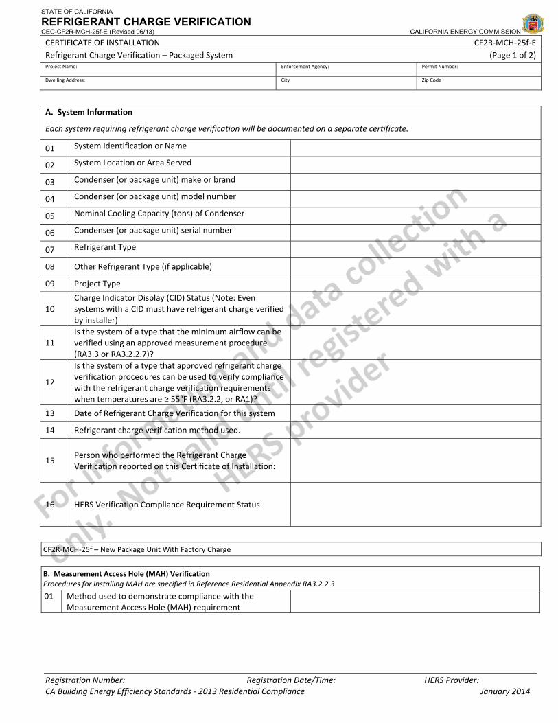
STATE OF CALIFORNIA
REFRIGERANT CHARGE VERIFICATION CEC-CF2R-MCH-25f-E (Revised 06/13) CALIFORNIA ENERGY COMMISSION
CERTIFICATE OF INSTALLATION CF2R‐MCH‐25f‐E Refrigerant Charge Verification – Packaged System (Page 1 of 2) Project Name: Enforcement Agency: Permit Number:
Dwelling Address: City Zip Code
Registration Number: Registration Date/Time: HERS Provider: CA Building Energy Efficiency Standards ‐ 2013 Residential Compliance January 2014
A. System Information
Each system requiring refrigerant charge verification will be documented on a separate certificate.
01 System Identification or Name
02 System Location or Area Served
03 Condenser (or package unit) make or brand
04 Condenser (or package unit) model number
05 Nominal Cooling Capacity (tons) of Condenser
06 Condenser (or package unit) serial number
07 Refrigerant Type
08 Other Refrigerant Type (if applicable)
09 Project Type
10 Charge Indicator Display (CID) Status (Note: Even systems with a CID must have refrigerant charge verified by installer)
11 Is the system of a type that the minimum airflow can be verified using an approved measurement procedure (RA3.3 or RA3.2.2.7)?
12
Is the system of a type that approved refrigerant charge verification procedures can be used to verify compliance with the refrigerant charge verification requirements when temperatures are ≥ 55°F (RA3.2.2, or RA1)?
13 Date of Refrigerant Charge Verification for this system
14 Refrigerant charge verification method used.
15 Person who performed the Refrigerant Charge Verification reported on this Certificate of Installation:
16 HERS Verification Compliance Requirement Status
CF2R‐MCH‐25f – New Package Unit With Factory Charge
B. Measurement Access Hole (MAH) Verification Procedures for installing MAH are specified in Reference Residential Appendix RA3.2.2.3
01 Method used to demonstrate compliance with the Measurement Access Hole (MAH) requirement
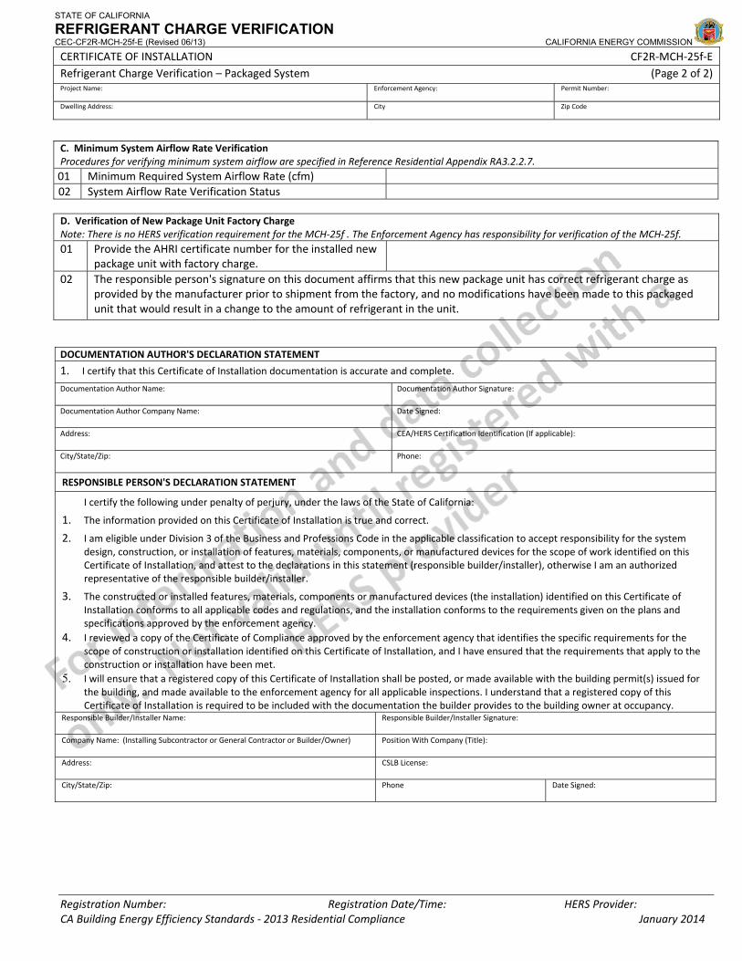
STATE OF CALIFORNIA
REFRIGERANT CHARGE VERIFICATION CEC-CF2R-MCH-25f-E (Revised 06/13) CALIFORNIA ENERGY COMMISSION
CERTIFICATE OF INSTALLATION CF2R‐MCH‐25f‐E Refrigerant Charge Verification – Packaged System (Page 2 of 2) Project Name: Enforcement Agency: Permit Number:
Dwelling Address: City Zip Code
Registration Number: Registration Date/Time: HERS Provider: CA Building Energy Efficiency Standards ‐ 2013 Residential Compliance January 2014
C. Minimum System Airflow Rate Verification Procedures for verifying minimum system airflow are specified in Reference Residential Appendix RA3.2.2.7. 01 Minimum Required System Airflow Rate (cfm) 02 System Airflow Rate Verification Status D. Verification of New Package Unit Factory Charge Note: There is no HERS verification requirement for the MCH‐25f . The Enforcement Agency has responsibility for verification of the MCH‐25f. 01 Provide the AHRI certificate number for the installed new
package unit with factory charge.
02 The responsible person's signature on this document affirms that this new package unit has correct refrigerant charge as provided by the manufacturer prior to shipment from the factory, and no modifications have been made to this packaged unit that would result in a change to the amount of refrigerant in the unit.
DOCUMENTATION AUTHOR'S DECLARATION STATEMENT
1. I certify that this Certificate of Installation documentation is accurate and complete.
Documentation Author Name: Documentation Author Signature:
Documentation Author Company Name: Date Signed:
Address: CEA/HERS Certification Identification (If applicable):
City/State/Zip: Phone:
RESPONSIBLE PERSON'S DECLARATION STATEMENT
I certify the following under penalty of perjury, under the laws of the State of California:
1. The information provided on this Certificate of Installation is true and correct.
2. I am eligible under Division 3 of the Business and Professions Code in the applicable classification to accept responsibility for the system design, construction, or installation of features, materials, components, or manufactured devices for the scope of work identified on this Certificate of Installation, and attest to the declarations in this statement (responsible builder/installer), otherwise I am an authorized representative of the responsible builder/installer.
3. The constructed or installed features, materials, components or manufactured devices (the installation) identified on this Certificate of Installation conforms to all applicable codes and regulations, and the installation conforms to the requirements given on the plans and specifications approved by the enforcement agency.
4. I reviewed a copy of the Certificate of Compliance approved by the enforcement agency that identifies the specific requirements for the scope of construction or installation identified on this Certificate of Installation, and I have ensured that the requirements that apply to the construction or installation have been met.
5. I will ensure that a registered copy of this Certificate of Installation shall be posted, or made available with the building permit(s) issued for the building, and made available to the enforcement agency for all applicable inspections. I understand that a registered copy of this Certificate of Installation is required to be included with the documentation the builder provides to the building owner at occupancy.
Responsible Builder/Installer Name: Responsible Builder/Installer Signature:
Company Name: (Installing Subcontractor or General Contractor or Builder/Owner) Position With Company (Title):
Address: CSLB License:
City/State/Zip: Phone Date Signed:
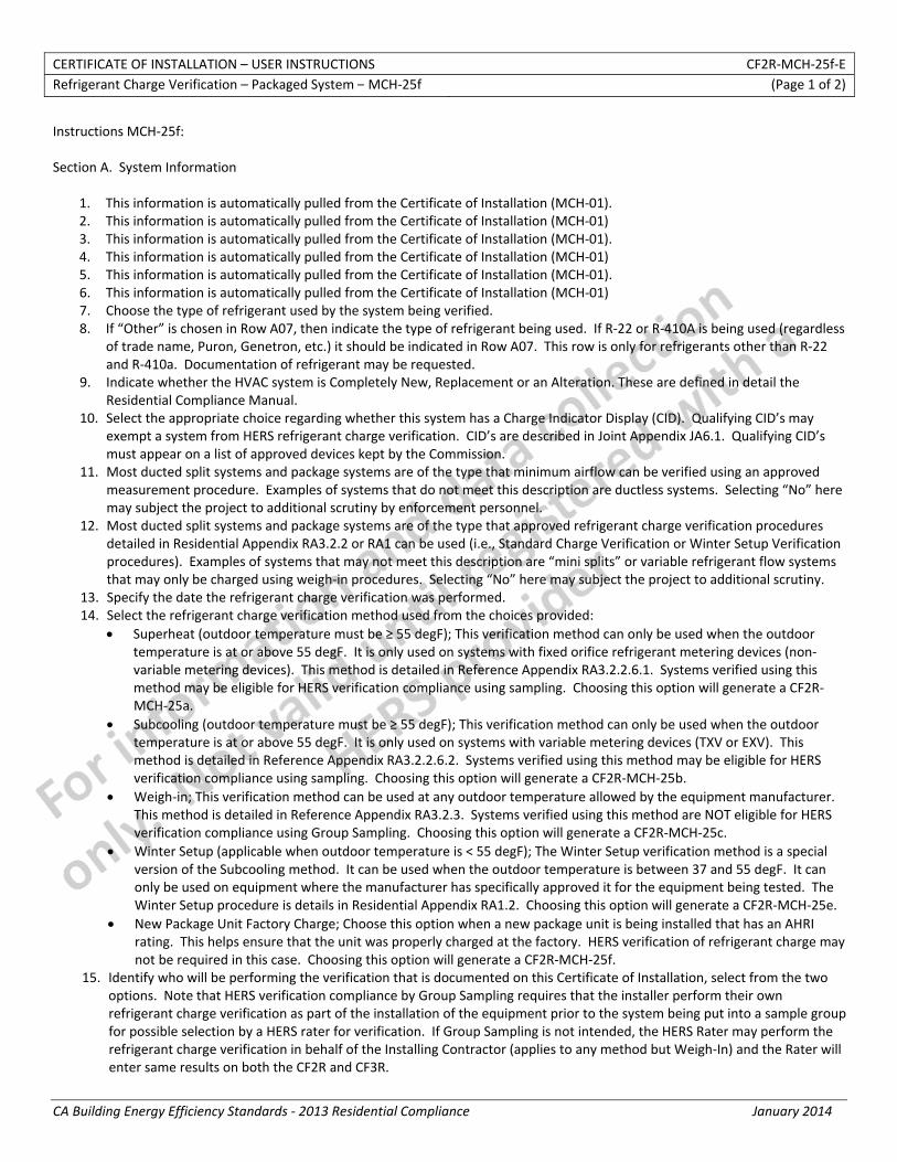
CERTIFICATE OF INSTALLATION – USER INSTRUCTIONS CF2R‐MCH‐25f‐E Refrigerant Charge Verification – Packaged System – MCH‐25f (Page 1 of 2)
CA Building Energy Efficiency Standards ‐ 2013 Residential Compliance January 2014
Instructions MCH‐25f: Section A. System Information
1. This information is automatically pulled from the Certificate of Installation (MCH‐01). 2. This information is automatically pulled from the Certificate of Installation (MCH‐01) 3. This information is automatically pulled from the Certificate of Installation (MCH‐01). 4. This information is automatically pulled from the Certificate of Installation (MCH‐01) 5. This information is automatically pulled from the Certificate of Installation (MCH‐01). 6. This information is automatically pulled from the Certificate of Installation (MCH‐01) 7. Choose the type of refrigerant used by the system being verified. 8. If “Other” is chosen in Row A07, then indicate the type of refrigerant being used. If R‐22 or R‐410A is being used (regardless
of trade name, Puron, Genetron, etc.) it should be indicated in Row A07. This row is only for refrigerants other than R‐22 and R‐410a. Documentation of refrigerant may be requested.
9. Indicate whether the HVAC system is Completely New, Replacement or an Alteration. These are defined in detail the Residential Compliance Manual.
10. Select the appropriate choice regarding whether this system has a Charge Indicator Display (CID). Qualifying CID’s may exempt a system from HERS refrigerant charge verification. CID’s are described in Joint Appendix JA6.1. Qualifying CID’s must appear on a list of approved devices kept by the Commission.
11. Most ducted split systems and package systems are of the type that minimum airflow can be verified using an approved measurement procedure. Examples of systems that do not meet this description are ductless systems. Selecting “No” here may subject the project to additional scrutiny by enforcement personnel.
12. Most ducted split systems and package systems are of the type that approved refrigerant charge verification procedures detailed in Residential Appendix RA3.2.2 or RA1 can be used (i.e., Standard Charge Verification or Winter Setup Verification procedures). Examples of systems that may not meet this description are “mini splits” or variable refrigerant flow systems that may only be charged using weigh‐in procedures. Selecting “No” here may subject the project to additional scrutiny.
13. Specify the date the refrigerant charge verification was performed. 14. Select the refrigerant charge verification method used from the choices provided:
• Superheat (outdoor temperature must be ≥ 55 degF); This verification method can only be used when the outdoor temperature is at or above 55 degF. It is only used on systems with fixed orifice refrigerant metering devices (non‐variable metering devices). This method is detailed in Reference Appendix RA3.2.2.6.1. Systems verified using this method may be eligible for HERS verification compliance using sampling. Choosing this option will generate a CF2R‐MCH‐25a.
• Subcooling (outdoor temperature must be ≥ 55 degF); This verification method can only be used when the outdoor temperature is at or above 55 degF. It is only used on systems with variable metering devices (TXV or EXV). This method is detailed in Reference Appendix RA3.2.2.6.2. Systems verified using this method may be eligible for HERS verification compliance using sampling. Choosing this option will generate a CF2R‐MCH‐25b.
• Weigh‐in; This verification method can be used at any outdoor temperature allowed by the equipment manufacturer. This method is detailed in Reference Appendix RA3.2.3. Systems verified using this method are NOT eligible for HERS verification compliance using Group Sampling. Choosing this option will generate a CF2R‐MCH‐25c.
• Winter Setup (applicable when outdoor temperature is < 55 degF); The Winter Setup verification method is a special version of the Subcooling method. It can be used when the outdoor temperature is between 37 and 55 degF. It can only be used on equipment where the manufacturer has specifically approved it for the equipment being tested. The Winter Setup procedure is details in Residential Appendix RA1.2. Choosing this option will generate a CF2R‐MCH‐25e.
• New Package Unit Factory Charge; Choose this option when a new package unit is being installed that has an AHRI rating. This helps ensure that the unit was properly charged at the factory. HERS verification of refrigerant charge may not be required in this case. Choosing this option will generate a CF2R‐MCH‐25f.
15. Identify who will be performing the verification that is documented on this Certificate of Installation, select from the two options. Note that HERS verification compliance by Group Sampling requires that the installer perform their own refrigerant charge verification as part of the installation of the equipment prior to the system being put into a sample group for possible selection by a HERS rater for verification. If Group Sampling is not intended, the HERS Rater may perform the refrigerant charge verification in behalf of the Installing Contractor (applies to any method but Weigh‐In) and the Rater will enter same results on both the CF2R and CF3R.

CERTIFICATE OF INSTALLATION – USER INSTRUCTIONS CF2R‐MCH‐25f‐E Refrigerant Charge Verification – Packaged System – MCH‐25f (Page 2 of 2)
CA Building Energy Efficiency Standards ‐ 2013 Residential Compliance January 2014
16. The Group Sampling status is automatically displayed based on the input results of Row A14 and Row A15. Group Sampling procedures are detailed Residential Appendix RA2.3.
Section B. Measurement Access Hole (MAH) Verification
1. Indicate the method used to demonstrate compliance with the MAH requirement by selecting the appropriate method from the drop down list. Procedures for installing MAH’s are detailed in RA3.2.2.3. Selecting that the MAH cannot be installed consistent with Figure 3.2‐1 may result in additional scrutiny by enforcement personnel.
Section C. Minimum System Airflow Rate Verification
1. This information is automatically calculated based on the information given in line A09. This is the target minimum system airflow required for the system being verified.
2. This information is automatically calculated based on either the MCH‐23 which documents the measured airflow of the system being verified. If the measured airflow is not adequate it will not comply with the airflow requirements and refrigerant charge verification cannot be performed.
Section D. Verification of New Package Unit Factory Charge
1. Only AHRI certified package units can qualify for having an appropriate factory charge. Provide and accurate AHRI certificate number here and be prepared to provide supporting documentation upon request.
2. By signing the Declaration Statement at the bottom of this form, the installer is declaring that the package unit was an AHRI certified unit and that no modifications were made to the unit to change the factory charge.

STATE OF CALIFORNIA
VERIFICATION OF HIGH SEER & EER EQUIPMENT CEC-CF2R-MCH-26-H (Revised 06/13) CALIFORNIA ENERGY COMMISSION
CERTIFICATE OF INSTALLATION CF2R‐MCH‐26‐H Verification of High SEER &EER Equipment (Page 1 of 2) Project Name: Enforcement Agency: Permit Number:
Dwelling Address: City Zip Code
Registration Number: Registration Date/Time: HERS Provider: CA Building Energy Efficiency Standards ‐ 2013 Residential Compliance January 2014
Procedures for verification of High SEER and EER Equipment are described in Reference Appendix RA3.4. Each HVAC system requiring verification must use a separate form.
A. System Information
01 Required SEER from the CF1R Report SEER
02 Required EER from the CF1R Report EER
03 System Name or Identification/Tag
04 System Location or Area Served
05 List AHRI certification number for the installed air conditioning equipment from http://www.ahridirectory.org
06 Is Air Handler/Furnace make and model Included in the AHRI certification from row A05?
07 Is time delay relay installed (Verify using manufactures data)?
08 Is a TXV included in the AHRI certification from row A05 or manufactures data?
09 Outdoor Condenser ‐ Installed Manufacturer Name
10 Outdoor Condenser ‐ Installed Model Number
11 Outdoor Condenser ‐ Installed Serial Number
12 Inside Coil ‐ Installed Manufacture Name
13 Inside Coil ‐ Installed Model Number
14 Inside Coil ‐ Installed Serial Number
15 Air Handler/Furnace ‐ Installed Manufacture Name
16 Air Handler/Furnace ‐ Installed Model Number
17 Air Handler/Furnace ‐ Installed Serial Number
B. Verified Cooling System Efficiency ‐ SEER
01 SEER listed on AHRI Certification row A05 SEER
02 Yes No Is the AHRI certified SEER row B01 the same or better than required by the CF‐1R row A01
03 Yes No Are the Manufacturer Names and Model Numbers listed on the AHRI certification from row A05 the same as what was installed?
04 Yes No Are the Manufacturer Names and Model Numbers listed on the AHRI certification from row A05 the same as what is listed on rows A09, A10, A12 and A13?
05 Compliance Statement:
C. Verified Cooling System Efficiency ‐ EER
01 EER listed on AHRI Certification row A05 EER
02 Yes No Is the AHRI certified EER C01 the same or better than required by the CF1R row A02
03 Yes No Are the Manufacturer Names and Model Numbers listed on the AHRI certification from row A05 the same as what was installed?
04 Yes No Are the Manufacturer Names and Model Numbers listed on the AHRI certification from row A05 the same as what is listed on rows A09, A10, A12 and A13?
05 Compliance Statement:
D. Verified Cooling System Efficiency ‐ Air Handler/Furnace
01 Yes No Are the Manufacturer Names and Model Numbers listed on the AHRI certification from row A05 the same as what was installed?
02 Yes No Are the Manufacturer Names and Model Numbers listed on the AHRI certification from row A05 the same as what is listed on rows A15 and A16?
03 Compliance Statement:
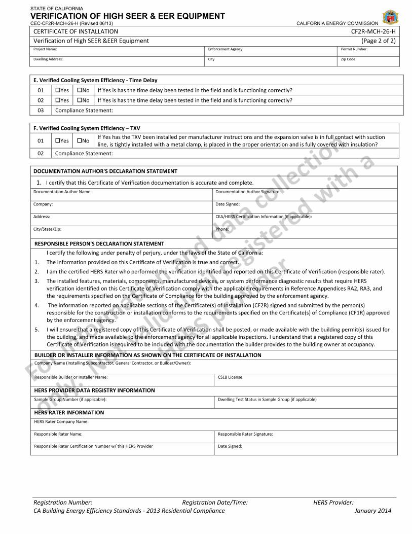
STATE OF CALIFORNIA
VERIFICATION OF HIGH SEER & EER EQUIPMENT CEC-CF2R-MCH-26-H (Revised 06/13) CALIFORNIA ENERGY COMMISSION
CERTIFICATE OF INSTALLATION CF2R‐MCH‐26‐H Verification of High SEER &EER Equipment (Page 2 of 2) Project Name: Enforcement Agency: Permit Number:
Dwelling Address: City Zip Code
Registration Number: Registration Date/Time: HERS Provider: CA Building Energy Efficiency Standards ‐ 2013 Residential Compliance January 2014
E. Verified Cooling System Efficiency ‐ Time Delay
01 Yes No If Yes is has the time delay been tested in the field and is functioning correctly?
02 Yes No If Yes is has the time delay been tested in the field and is functioning correctly?
03 Compliance Statement:
F. Verified Cooling System Efficiency – TXV
01 Yes No If Yes has the TXV been installed per manufacturer instructions and the expansion valve is in full contact with suction line, is tightly installed with a metal clamp, is placed in the proper orientation and is fully covered with insulation?
02 Compliance Statement:
DOCUMENTATION AUTHOR'S DECLARATION STATEMENT
1. I certify that this Certificate of Verification documentation is accurate and complete. Documentation Author Name: Documentation Author Signature:
Company: Date Signed:
Address: CEA/HERS Certification Information (if applicable):
City/State/Zip: Phone:
RESPONSIBLE PERSON'S DECLARATION STATEMENT
I certify the following under penalty of perjury, under the laws of the State of California:
1. The information provided on this Certificate of Verification is true and correct.
2. I am the certified HERS Rater who performed the verification identified and reported on this Certificate of Verification (responsible rater).
3. The installed features, materials, components, manufactured devices, or system performance diagnostic results that require HERS verification identified on this Certificate of Verification comply with the applicable requirements in Reference Appendices RA2, RA3, and the requirements specified on the Certificate of Compliance for the building approved by the enforcement agency.
4. The information reported on applicable sections of the Certificate(s) of Installation (CF2R) signed and submitted by the person(s) responsible for the construction or installation conforms to the requirements specified on the Certificate(s) of Compliance (CF1R) approved by the enforcement agency.
5. I will ensure that a registered copy of this Certificate of Verification shall be posted, or made available with the building permit(s) issued for the building, and made available to the enforcement agency for all applicable inspections. I understand that a registered copy of this Certificate of Verification is required to be included with the documentation the builder provides to the building owner at occupancy.
BUILDER OR INSTALLER INFORMATION AS SHOWN ON THE CERTIFICATE OF INSTALLATION Company Name (Installing Subcontractor, General Contractor, or Builder/Owner):
Responsible Builder or Installer Name: CSLB License:
HERS PROVIDER DATA REGISTRY INFORMATION
Sample Group Number (if applicable): Dwelling Test Status in Sample Group (if applicable)
HERS RATER INFORMATION
HERS Rater Company Name:
Responsible Rater Name: Responsible Rater Signature:
Responsible Rater Certification Number w/ this HERS Provider Date Signed:
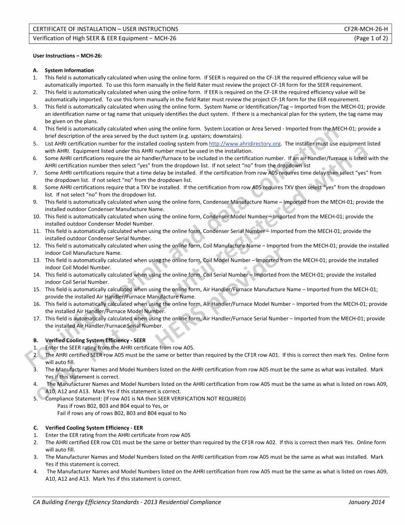
CERTIFICATE OF INSTALLATION – USER INSTRUCTIONS CF2R‐MCH‐26‐H Verification of High SEER & EER Equipment – MCH‐26 (Page 1 of 2)
CA Building Energy Efficiency Standards ‐ 2013 Residential Compliance January 2014
User Instructions – MCH‐26: A. System Information 1. This field is automatically calculated when using the online form. If SEER is required on the CF‐1R the required efficiency value will be
automatically imported. To use this form manually in the field Rater must review the project CF‐1R form for the SEER requirement. 2. This field is automatically calculated when using the online form. If EER is required on the CF‐1R the required efficiency value will be
automatically imported. To use this form manually in the field Rater must review the project CF‐1R form for the EER requirement. 3. This field is automatically calculated when using the online form. System Name or Identification/Tag – Imported from the MECH‐01; provide
an identification name or tag name that uniquely identifies the duct system. If there is a mechanical plan for the system, the tag name may be given on the plans.
4. This field is automatically calculated when using the online form. System Location or Area Served ‐ Imported from the MECH‐01; provide a brief description of the area served by the duct system (e.g. upstairs; downstairs).
5. List AHRI certification number for the installed cooling system from http://www.ahridirectory.org. The installer must use equipment listed with AHRI. Equipment listed under this AHRI number must be used in the installation.
6. Some AHRI certifications require the air handler/furnace to be included in the certification number. If an air handler/furnace is listed with the AHRI certification number then select “yes” from the dropdown list. If not select “no” from the dropdown list
7. Some AHRI certifications require that a time delay be installed. If the certification from row A05 requires time delay then select “yes” from the dropdown list. If not select “no” from the dropdown list.
8. Some AHRI certifications require that a TXV be installed. If the certification from row A05 requires TXV then select “yes” from the dropdown list. If not select “no” from the dropdown list.
9. This field is automatically calculated when using the online form, Condenser Manufacture Name – Imported from the MECH‐01; provide the installed outdoor Condenser Manufacture Name.
10. This field is automatically calculated when using the online form, Condenser Model Number – Imported from the MECH‐01; provide the installed outdoor Condenser Model Number.
11. This field is automatically calculated when using the online form, Condenser Serial Number – Imported from the MECH‐01; provide the installed outdoor Condenser Serial Number.
12. This field is automatically calculated when using the online form, Coil Manufacture Name – Imported from the MECH‐01; provide the installed indoor Coil Manufacture Name.
13. This field is automatically calculated when using the online form, Coil Model Number – Imported from the MECH‐01; provide the installed indoor Coil Model Number.
14. This field is automatically calculated when using the online form, Coil Serial Number – Imported from the MECH‐01; provide the installed indoor Coil Serial Number.
15. This field is automatically calculated when using the online form, Air Handler/Furnace Manufacture Name – Imported from the MECH‐01; provide the installed Air Handler/Furnace Manufacture Name.
16. This field is automatically calculated when using the online form, Air Handler/Furnace Model Number – Imported from the MECH‐01; provide the installed Air Handler/Furnace Model Number.
17. This field is automatically calculated when using the online form, Air Handler/Furnace Serial Number – Imported from the MECH‐01; provide the installed Air Handler/Furnace Serial Number.
B. Verified Cooling System Efficiency ‐ SEER 1. Enter the SEER rating from the AHRI certificate from row A05. 2. The AHRI certified SEER row A05 must be the same or better than required by the CF1R row A01. If this is correct then mark Yes. Online form
will auto fill. 3. The Manufacturer Names and Model Numbers listed on the AHRI certification from row A05 must be the same as what was installed. Mark
Yes if this statement is correct. 4. The Manufacturer Names and Model Numbers listed on the AHRI certification from row A05 must be the same as what is listed on rows A09,
A10, A12 and A13. Mark Yes if this statement is correct. 5. Compliance Statement: (If row A01 is NA then SEER VERIFICATION NOT REQUIRED)
Pass if rows B02, B03 and B04 equal to Yes, or Fail if rows any of rows B02, B03 and B04 equal to No
C. Verified Cooling System Efficiency ‐ EER 1. Enter the EER rating from the AHRI certificate from row A05 2. The AHRI certified EER row C01 must be the same or better than required by the CF1R row A02. If this is correct then mark Yes. Online form
will auto fill. 3. The Manufacturer Names and Model Numbers listed on the AHRI certification from row A05 must be the same as what was installed. Mark
Yes if this statement is correct. 4. The Manufacturer Names and Model Numbers listed on the AHRI certification from row A05 must be the same as what is listed on rows A09,
A10, A12 and A13. Mark Yes if this statement is correct.
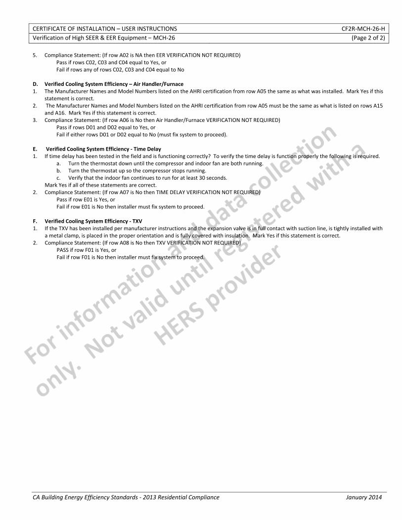
CERTIFICATE OF INSTALLATION – USER INSTRUCTIONS CF2R‐MCH‐26‐H Verification of High SEER & EER Equipment – MCH‐26 (Page 2 of 2)
CA Building Energy Efficiency Standards ‐ 2013 Residential Compliance January 2014
5. Compliance Statement: (If row A02 is NA then EER VERIFICATION NOT REQUIRED) Pass if rows C02, C03 and C04 equal to Yes, or Fail if rows any of rows C02, C03 and C04 equal to No
D. Verified Cooling System Efficiency – Air Handler/Furnace 1. The Manufacturer Names and Model Numbers listed on the AHRI certification from row A05 the same as what was installed. Mark Yes if this
statement is correct. 2. The Manufacturer Names and Model Numbers listed on the AHRI certification from row A05 must be the same as what is listed on rows A15
and A16. Mark Yes if this statement is correct. 3. Compliance Statement: (If row A06 is No then Air Handler/Furnace VERIFICATION NOT REQUIRED)
Pass if rows D01 and D02 equal to Yes, or Fail if either rows D01 or D02 equal to No (must fix system to proceed).
E. Verified Cooling System Efficiency ‐ Time Delay 1. If time delay has been tested in the field and is functioning correctly? To verify the time delay is function properly the following is required.
a. Turn the thermostat down until the compressor and indoor fan are both running. b. Turn the thermostat up so the compressor stops running. c. Verify that the indoor fan continues to run for at least 30 seconds.
Mark Yes if all of these statements are correct. 2. Compliance Statement: (If row A07 is No then TIME DELAY VERIFICATION NOT REQUIRED)
Pass if row E01 is Yes, or Fail if row E01 is No then installer must fix system to proceed.
F. Verified Cooling System Efficiency ‐ TXV 1. If the TXV has been installed per manufacturer instructions and the expansion valve is in full contact with suction line, is tightly installed with
a metal clamp, is placed in the proper orientation and is fully covered with insulation. Mark Yes if this statement is correct. 2. Compliance Statement: (If row A08 is No then TXV VERIFICATION NOT REQUIRED)
PASS if row F01 is Yes, or Fail if row F01 is No then installer must fix system to proceed.
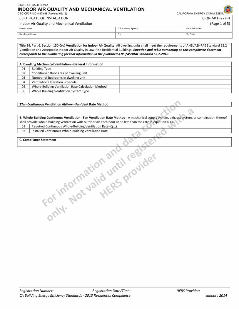
STATE OF CALIFORNIA
INDOOR AIR QUALITY AND MECHANICAL VENTILATION CEC-CF2R-MCH-27a-H (Revised 06/13) CALIFORNIA ENERGY COMMISSION
CERTIFICATE OF INSTALLATION CF2R‐MCH‐27a‐H Indoor Air Quality and Mechanical Ventilation (Page 1 of 5) Project Name: Enforcement Agency: Permit Number:
Dwelling Address: City Zip Code
Registration Number: Registration Date/Time: HERS Provider: CA Building Energy Efficiency Standards ‐ 2013 Residential Compliance January 2014
Title 24, Part 6, Section 150.0(o) Ventilation for Indoor Air Quality. All dwelling units shall meet the requirements of ANSI/ASHRAE Standard 62.2 Ventilation and Acceptable Indoor Air Quality in Low‐Rise Residential Buildings. Equation and table numbering on this compliance document corresponds to the numbering for that information in the published ANSI/ASHRAE Standard 62.2‐2010.
A. Dwelling Mechanical Ventilation ‐ General Information 01 Building Type 02 Conditioned floor area of dwelling unit 03 Number of bedrooms in dwelling unit 04 Ventilation Operation Schedule 05 Whole‐Building Ventilation Rate Calculation Method. 06 Whole Building Ventilation System Type
27a ‐ Continuous Ventilation Airflow ‐ Fan Vent Rate Method B. Whole‐Building Continuous Ventilation ‐ Fan Ventilation Rate Method ‐ A mechanical supply system, exhaust system, or combination thereof shall provide whole‐building ventilation with outdoor air each hour at no less than the rate in equation 4.1a. 01 Required Continuous Whole‐Building Ventilation Rate (Qfan) 02 Installed Continuous Whole‐Building Ventilation Rate
C. Compliance Statement
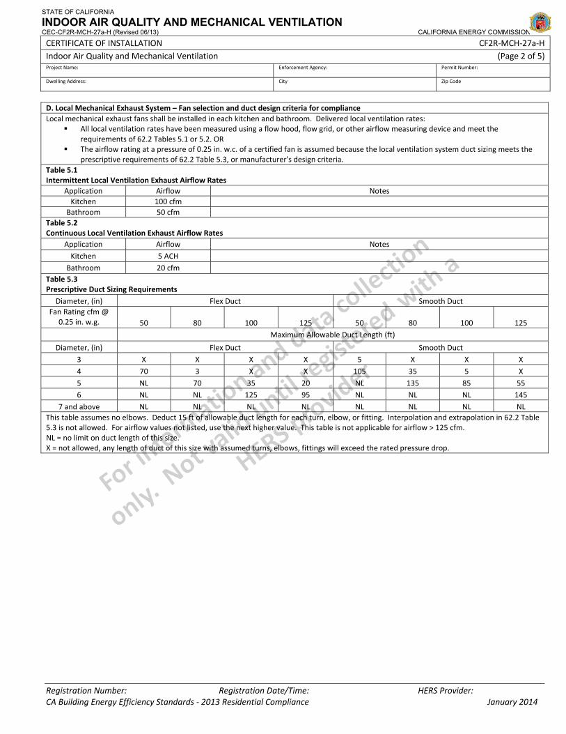
STATE OF CALIFORNIA
INDOOR AIR QUALITY AND MECHANICAL VENTILATION CEC-CF2R-MCH-27a-H (Revised 06/13) CALIFORNIA ENERGY COMMISSION
CERTIFICATE OF INSTALLATION CF2R‐MCH‐27a‐H Indoor Air Quality and Mechanical Ventilation (Page 2 of 5) Project Name: Enforcement Agency: Permit Number:
Dwelling Address: City Zip Code
Registration Number: Registration Date/Time: HERS Provider: CA Building Energy Efficiency Standards ‐ 2013 Residential Compliance January 2014
D. Local Mechanical Exhaust System – Fan selection and duct design criteria for compliance Local mechanical exhaust fans shall be installed in each kitchen and bathroom. Delivered local ventilation rates:
All local ventilation rates have been measured using a flow hood, flow grid, or other airflow measuring device and meet the requirements of 62.2 Tables 5.1 or 5.2. OR
The airflow rating at a pressure of 0.25 in. w.c. of a certified fan is assumed because the local ventilation system duct sizing meets the prescriptive requirements of 62.2 Table 5.3, or manufacturer's design criteria.
Table 5.1 Intermittent Local Ventilation Exhaust Airflow Rates
Application Airflow Notes Kitchen 100 cfm
Bathroom 50 cfm Table 5.2 Continuous Local Ventilation Exhaust Airflow Rates
Application Airflow Notes Kitchen 5 ACH
Bathroom 20 cfm Table 5.3 Prescriptive Duct Sizing Requirements
Diameter, (in) Flex Duct Smooth Duct Fan Rating cfm @
0.25 in. w.g. 50 80 100 125 50 80 100 125 Maximum Allowable Duct Length (ft)
Diameter, (in) Flex Duct Smooth Duct 3 X X X X 5 X X X 4 70 3 X X 105 35 5 X 5 NL 70 35 20 NL 135 85 55 6 NL NL 125 95 NL NL NL 145
7 and above NL NL NL NL NL NL NL NL This table assumes no elbows. Deduct 15 ft of allowable duct length for each turn, elbow, or fitting. Interpolation and extrapolation in 62.2 Table 5.3 is not allowed. For airflow values not listed, use the next higher value. This table is not applicable for airflow > 125 cfm. NL = no limit on duct length of this size. X = not allowed, any length of duct of this size with assumed turns, elbows, fittings will exceed the rated pressure drop.
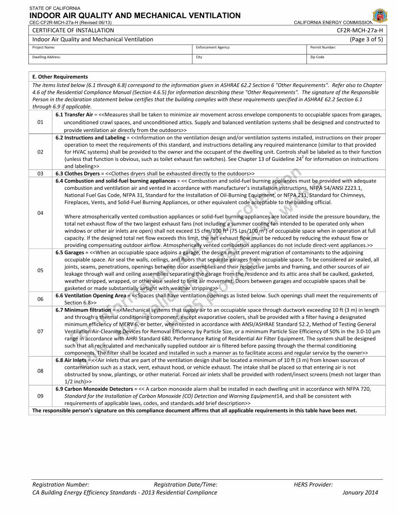
STATE OF CALIFORNIA
INDOOR AIR QUALITY AND MECHANICAL VENTILATION CEC-CF2R-MCH-27a-H (Revised 06/13) CALIFORNIA ENERGY COMMISSION
CERTIFICATE OF INSTALLATION CF2R‐MCH‐27a‐H Indoor Air Quality and Mechanical Ventilation (Page 3 of 5) Project Name: Enforcement Agency: Permit Number:
Dwelling Address: City Zip Code
Registration Number: Registration Date/Time: HERS Provider: CA Building Energy Efficiency Standards ‐ 2013 Residential Compliance January 2014
E. Other Requirements
The items listed below (6.1 through 6.8) correspond to the information given in ASHRAE 62.2 Section 6 "Other Requirements". Refer also to Chapter 4.6 of the Residential Compliance Manual (Section 4.6.5) for information describing these "Other Requirements". The signature of the Responsible Person in the declaration statement below certifies that the building complies with these requirements specified in ASHRAE 62.2 Section 6.1 through 6.9 if applicable.
01 6.1 Transfer Air = <<Measures shall be taken to minimize air movement across envelope components to occupiable spaces from garages,
unconditioned crawl spaces, and unconditioned attics. Supply and balanced ventilation systems shall be designed and constructed to provide ventilation air directly from the outdoors>>
02
6.2 Instructions and Labeling = <<Information on the ventilation design and/or ventilation systems installed, instructions on their proper operation to meet the requirements of this standard, and instructions detailing any required maintenance (similar to that provided for HVAC systems) shall be provided to the owner and the occupant of the dwelling unit. Controls shall be labeled as to their function (unless that function is obvious, such as toilet exhaust fan switches). See Chapter 13 of Guideline 242 for information on instructions and labeling>>
03 6.3 Clothes Dryers = <<Clothes dryers shall be exhausted directly to the outdoors>>
04
6.4 Combustion and solid‐fuel burning appliances = << Combustion and solid‐fuel burning appliances must be provided with adequate combustion and ventilation air and vented in accordance with manufacturer’s installation instructions, NFPA 54/ANSI Z223.1, National Fuel Gas Code, NFPA 31, Standard for the Installation of Oil‐Burning Equipment, or NFPA 211, Standard for Chimneys, Fireplaces, Vents, and Solid‐Fuel Burning Appliances, or other equivalent code acceptable to the building official.
Where atmospherically vented combustion appliances or solid‐fuel burning appliances are located inside the pressure boundary, the total net exhaust flow of the two largest exhaust fans (not including a summer cooling fan intended to be operated only when windows or other air inlets are open) shall not exceed 15 cfm/100 ft² (75 Lps/100 m2) of occupiable space when in operation at full capacity. If the designed total net flow exceeds this limit, the net exhaust flow must be reduced by reducing the exhaust flow or providing compensating outdoor airflow. Atmospherically vented combustion appliances do not include direct‐vent appliances.>>
05
6.5 Garages = <<When an occupiable space adjoins a garage, the design must prevent migration of contaminants to the adjoining occupiable space. Air seal the walls, ceilings, and floors that separate garages from occupiable space. To be considered air sealed, all joints, seams, penetrations, openings between door assemblies and their respective jambs and framing, and other sources of air leakage through wall and ceiling assemblies separating the garage from the residence and its attic area shall be caulked, gasketed, weather stripped, wrapped, or otherwise sealed to limit air movement. Doors between garages and occupiable spaces shall be gasketed or made substantially airtight with weather stripping>>
06 6.6 Ventilation Opening Area = <<Spaces shall have ventilation openings as listed below. Such openings shall meet the requirements of
Section 6.8>>
07
6.7 Minimum filtration = <<Mechanical systems that supply air to an occupiable space through ductwork exceeding 10 ft (3 m) in length and through a thermal conditioning component, except evaporative coolers, shall be provided with a filter having a designated minimum efficiency of MERV 6, or better, when tested in accordance with ANSI/ASHRAE Standard 52.2, Method of Testing General Ventilation Air‐Cleaning Devices for Removal Efficiency by Particle Size, or a minimum Particle Size Efficiency of 50% in the 3.0‐10 µm range in accordance with AHRI Standard 680, Performance Rating of Residential Air Filter Equipment. The system shall be designed such that all recirculated and mechanically supplied outdoor air is filtered before passing through the thermal conditioning components. The filter shall be located and installed in such a manner as to facilitate access and regular service by the owner>>
08
6.8 Air Inlets = <<Air inlets that are part of the ventilation design shall be located a minimum of 10 ft (3 m) from known sources of contamination such as a stack, vent, exhaust hood, or vehicle exhaust. The intake shall be placed so that entering air is not obstructed by snow, plantings, or other material. Forced air inlets shall be provided with rodent/insect screens (mesh not larger than 1/2 inch)>>
09 6.9 Carbon Monoxide Detectors = << A carbon monoxide alarm shall be installed in each dwelling unit in accordance with NFPA 720,
Standard for the Installation of Carbon Monoxide (CO) Detection and Warning Equipment14, and shall be consistent with requirements of applicable laws, codes, and standards.add brief description>>
The responsible person’s signature on this compliance document affirms that all applicable requirements in this table have been met.
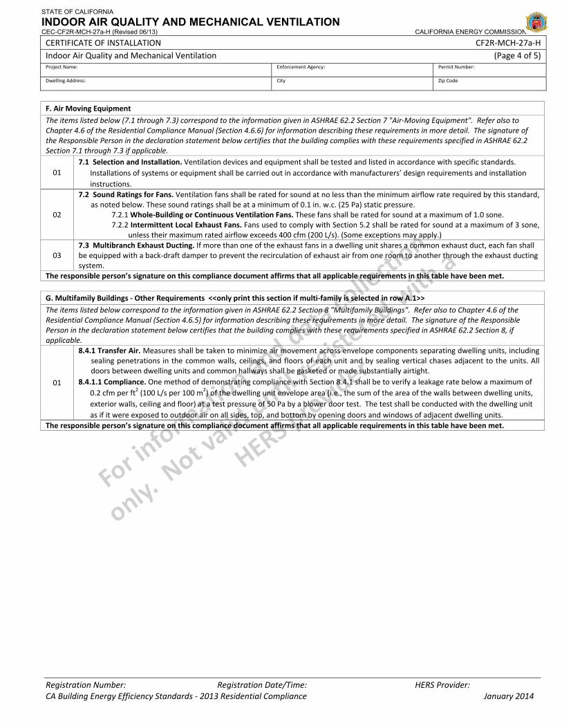
STATE OF CALIFORNIA
INDOOR AIR QUALITY AND MECHANICAL VENTILATION CEC-CF2R-MCH-27a-H (Revised 06/13) CALIFORNIA ENERGY COMMISSION
CERTIFICATE OF INSTALLATION CF2R‐MCH‐27a‐H Indoor Air Quality and Mechanical Ventilation (Page 4 of 5) Project Name: Enforcement Agency: Permit Number:
Dwelling Address: City Zip Code
Registration Number: Registration Date/Time: HERS Provider: CA Building Energy Efficiency Standards ‐ 2013 Residential Compliance January 2014
F. Air Moving Equipment
The items listed below (7.1 through 7.3) correspond to the information given in ASHRAE 62.2 Section 7 "Air‐Moving Equipment". Refer also to Chapter 4.6 of the Residential Compliance Manual (Section 4.6.6) for information describing these requirements in more detail. The signature of the Responsible Person in the declaration statement below certifies that the building complies with these requirements specified in ASHRAE 62.2 Section 7.1 through 7.3 if applicable.
01 7.1 Selection and Installation. Ventilation devices and equipment shall be tested and listed in accordance with specific standards.
Installations of systems or equipment shall be carried out in accordance with manufacturers’ design requirements and installation instructions.
02
7.2 Sound Ratings for Fans. Ventilation fans shall be rated for sound at no less than the minimum airflow rate required by this standard, as noted below. These sound ratings shall be at a minimum of 0.1 in. w.c. (25 Pa) static pressure.
7.2.1 Whole‐Building or Continuous Ventilation Fans. These fans shall be rated for sound at a maximum of 1.0 sone. 7.2.2 Intermittent Local Exhaust Fans. Fans used to comply with Section 5.2 shall be rated for sound at a maximum of 3 sone,
unless their maximum rated airflow exceeds 400 cfm (200 L/s). (Some exceptions may apply.)
03 7.3 Multibranch Exhaust Ducting. If more than one of the exhaust fans in a dwelling unit shares a common exhaust duct, each fan shall be equipped with a back‐draft damper to prevent the recirculation of exhaust air from one room to another through the exhaust ducting system.
The responsible person’s signature on this compliance document affirms that all applicable requirements in this table have been met.
G. Multifamily Buildings ‐ Other Requirements <<only print this section if multi‐family is selected in row A.1>>
The items listed below correspond to the information given in ASHRAE 62.2 Section 8 "Multifamily Buildings". Refer also to Chapter 4.6 of the Residential Compliance Manual (Section 4.6.5) for information describing these requirements in more detail. The signature of the Responsible Person in the declaration statement below certifies that the building complies with these requirements specified in ASHRAE 62.2 Section 8, if applicable.
01
8.4.1 Transfer Air. Measures shall be taken to minimize air movement across envelope components separating dwelling units, including sealing penetrations in the common walls, ceilings, and floors of each unit and by sealing vertical chases adjacent to the units. All doors between dwelling units and common hallways shall be gasketed or made substantially airtight.
8.4.1.1 Compliance. One method of demonstrating compliance with Section 8.4.1 shall be to verify a leakage rate below a maximum of 0.2 cfm per ft2 (100 L/s per 100 m2) of the dwelling unit envelope area (i.e., the sum of the area of the walls between dwelling units, exterior walls, ceiling and floor) at a test pressure of 50 Pa by a blower door test. The test shall be conducted with the dwelling unit as if it were exposed to outdoor air on all sides, top, and bottom by opening doors and windows of adjacent dwelling units.
The responsible person’s signature on this compliance document affirms that all applicable requirements in this table have been met.
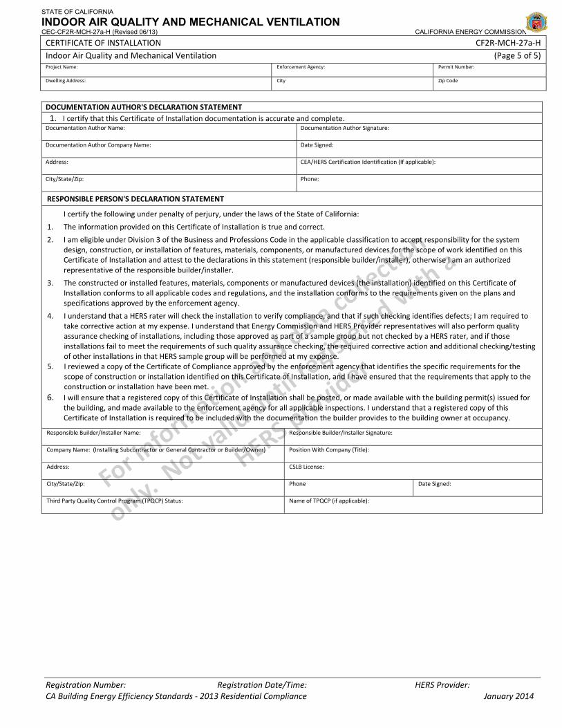
STATE OF CALIFORNIA
INDOOR AIR QUALITY AND MECHANICAL VENTILATION CEC-CF2R-MCH-27a-H (Revised 06/13) CALIFORNIA ENERGY COMMISSION
CERTIFICATE OF INSTALLATION CF2R‐MCH‐27a‐H Indoor Air Quality and Mechanical Ventilation (Page 5 of 5) Project Name: Enforcement Agency: Permit Number:
Dwelling Address: City Zip Code
Registration Number: Registration Date/Time: HERS Provider: CA Building Energy Efficiency Standards ‐ 2013 Residential Compliance January 2014
DOCUMENTATION AUTHOR'S DECLARATION STATEMENT1. I certify that this Certificate of Installation documentation is accurate and complete.
Documentation Author Name: Documentation Author Signature:
Documentation Author Company Name: Date Signed:
Address: CEA/HERS Certification Identification (If applicable):
City/State/Zip: Phone:
RESPONSIBLE PERSON'S DECLARATION STATEMENT
I certify the following under penalty of perjury, under the laws of the State of California:
1. The information provided on this Certificate of Installation is true and correct.
2. I am eligible under Division 3 of the Business and Professions Code in the applicable classification to accept responsibility for the system design, construction, or installation of features, materials, components, or manufactured devices for the scope of work identified on this Certificate of Installation and attest to the declarations in this statement (responsible builder/installer), otherwise I am an authorized representative of the responsible builder/installer.
3. The constructed or installed features, materials, components or manufactured devices (the installation) identified on this Certificate of Installation conforms to all applicable codes and regulations, and the installation conforms to the requirements given on the plans and specifications approved by the enforcement agency.
4. I understand that a HERS rater will check the installation to verify compliance, and that if such checking identifies defects; I am required to take corrective action at my expense. I understand that Energy Commission and HERS Provider representatives will also perform quality assurance checking of installations, including those approved as part of a sample group but not checked by a HERS rater, and if those installations fail to meet the requirements of such quality assurance checking, the required corrective action and additional checking/testing of other installations in that HERS sample group will be performed at my expense.
5. I reviewed a copy of the Certificate of Compliance approved by the enforcement agency that identifies the specific requirements for the scope of construction or installation identified on this Certificate of Installation, and I have ensured that the requirements that apply to the construction or installation have been met.
6. I will ensure that a registered copy of this Certificate of Installation shall be posted, or made available with the building permit(s) issued for the building, and made available to the enforcement agency for all applicable inspections. I understand that a registered copy of this Certificate of Installation is required to be included with the documentation the builder provides to the building owner at occupancy.
Responsible Builder/Installer Name: Responsible Builder/Installer Signature:
Company Name: (Installing Subcontractor or General Contractor or Builder/Owner) Position With Company (Title):
Address: CSLB License:
City/State/Zip: Phone Date Signed:
Third Party Quality Control Program (TPQCP) Status: Name of TPQCP (if applicable):
CERTIFICATE OF INSTALLATION ‐ USER INSTRUCTIONS CF2R‐MCH‐27a‐H Indoor Air Quality and Mechanical Ventilation – MCH‐27a ‐ Continuous ‐ Fan Ventilation Rate Method (Page 1 of 1)
CA Building Energy Efficiency Standards ‐ 2013 Residential Compliance January 2014
User Instructions – MCH‐27a: Section A. General Information 1 This information is automatically pulled from the CF1R Choices are “single family” and “low‐rise multifamily” 2 This information is automatically pulled from the CF1R. Value to be entered in the field equals the conditioned floor area of the space, in
square feet. 3 This information is automatically pulled from the CF1R. Value to be entered in the field equals the number of bedrooms in the home. 4 Select the Ventilation Operation Schedule method used from the choices provided:
• Continuous • Intermittent
5 Select the Whole Building Ventilation Rate Calculation Method from the choices provided: • Fan Ventilation Rate Method • Total Ventilation Rate Method
6 Select the Whole Building Ventilation System Type from the choices provided: • Standalone ‐ Exhaust • Standalone ‐ Supply • Standalone ‐ Balanced
Section B. Whole Building Continuous Ventilation – Fan Ventilation Rate Method 1 This value is automatically calculated using equation 4.1a. The equation used to calculate this value in the field equals:
a. If A01= Single Family then [(0.01 x conditioned floor area A02) + 7.5(Number of bedrooms A03 + 1)] = Continuous Whole‐Building Ventilation Rate
b. If A01= Multifamily then [(0.03 x conditioned floor area A02) + 7.5(Number of bedrooms A03 + 1)] = Continuous Whole‐Building Ventilation Rate
2 User entered value equals the total mechanical ventilation in CFM
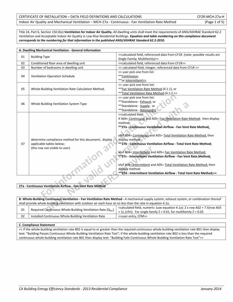
CERTIFICATE OF INSTALLATION – DATA FIELD DEFINITIONS AND CALCULATIONS CF2R‐MCH‐27a‐H Indoor Air Quality and Mechanical Ventilation – MCH‐27a ‐ Continuous ‐ Fan Ventilation Rate Method (Page 1 of 5)
CA Building Energy Efficiency Standards ‐ 2013 Residential Compliance January 2014
Title 24, Part 6, Section 150.0(o) Ventilation for Indoor Air Quality. All dwelling units shall meet the requirements of ANSI/ASHRAE Standard 62.2 Ventilation and Acceptable Indoor Air Quality in Low‐Rise Residential Buildings. Equation and table numbering on this compliance document corresponds to the numbering for that information in the published ANSI/ASHRAE Standard 62.2‐2010.
A. Dwelling Mechanical Ventilation ‐ General Information
01 Building Type <<calculated field, referenced data from CF1R. (note: possible results are Single Family; Multifamily)>>
02 Conditioned floor area of dwelling unit <<calculated field, referenced data from CF1R>> 03 Number of bedrooms in dwelling unit << calculated field, integer, referenced data from CF1R >>
04 Ventilation Operation Schedule << user pick one from list: **Continuous; **or Intermittent>>
05 Whole‐Building Ventilation Rate Calculation Method. << user pick one from list: **Fan Ventilation Rate Method (4.1.1), or **Total Ventilation Rate Method (4.1.2.>>
06 Whole Building Ventilation System Type
<< user pick one from list: **Standalone ‐ Exhaust; or **Standalone ‐ Supply; or **Standalone ‐ Balanced>>
07 determine compliance method for this document; display applicable tables below; (this row not visible to user)
<<calculated field: if A04= Continuous and A05= Fan Ventilation Rate Method; then display method: **27a ‐ Continuous Ventilation Airflow ‐ Fan Vent Rate Method; elsif A04= Continuous and A05= Total Ventilation Rate Method; then display method: **27b ‐ Continuous Ventilation Airflow ‐ Total Vent Rate Method; elsif A04= Intermittent and A05= Fan Ventilation Rate Method; **27c ‐ Intermittent Ventilation Airflow ‐ Fan Vent Rate Method; elsif A04= Intermittent and A05= Total Ventilation Rate Method; then display method: **27d ‐ Intermittent Ventilation Airflow ‐ Total Vent Rate Method;>>
27a ‐ Continuous Ventilation Airflow ‐ Fan Vent Rate Method B. Whole‐Building Continuous Ventilation ‐ Fan Ventilation Rate Method ‐ A mechanical supply system, exhaust system, or combination thereof shall provide whole‐building ventilation with outdoor air each hour at no less than the rate in equation 4.1a.
01 Required Continuous Whole‐Building Ventilation Rate (Qfan) <calculated field, numeric: (use equation 4.1a): Z x row A02 + 7.5(row A03 + 1), (cfm). For single family Z = 0.01, for multifamily Z = 0.03
02 Installed Continuous Whole‐Building Ventilation Rate <<user entry, CFM>> C. Compliance Statement << if the whole‐building ventilation rate B02 is equal to or greater than the required continuous whole‐building ventilation rate B01 then display text: "Building Passes Continuous Whole‐Building Ventilation Rate Test"; if the whole‐building ventilation rate B02 is less than the required continuous whole‐building ventilation rate B01 then display text: "Building Fails Continuous Whole‐Building Ventilation Rate Test">>
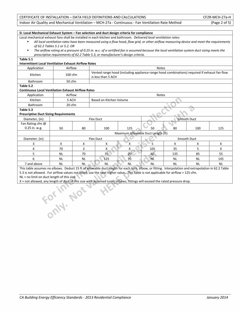
CERTIFICATE OF INSTALLATION – DATA FIELD DEFINITIONS AND CALCULATIONS CF2R‐MCH‐27a‐H Indoor Air Quality and Mechanical Ventilation – MCH‐27a ‐ Continuous ‐ Fan Ventilation Rate Method (Page 2 of 5)
CA Building Energy Efficiency Standards ‐ 2013 Residential Compliance January 2014
D. Local Mechanical Exhaust System – Fan selection and duct design criteria for compliance Local mechanical exhaust fans shall be installed in each kitchen and bathroom. Delivered local ventilation rates:
All local ventilation rates have been measured using a flow hood, flow grid, or other airflow measuring device and meet the requirements of 62.2 Tables 5.1 or 5.2. OR
The airflow rating at a pressure of 0.25 in. w.c. of a certified fan is assumed because the local ventilation system duct sizing meets the prescriptive requirements of 62.2 Table 5.3, or manufacturer's design criteria.
Table 5.1 Intermittent Local Ventilation Exhaust Airflow Rates
Application Airflow Notes
Kitchen 100 cfm Vented range hood (including appliance‐range hood combinations) required if exhaust fan flow is less than 5 ACH
Bathroom 50 cfm Table 5.2 Continuous Local Ventilation Exhaust Airflow Rates
Application Airflow Notes Kitchen 5 ACH Based on Kitchen Volume
Bathroom 20 cfm Table 5.3 Prescriptive Duct Sizing Requirements
Diameter, (in) Flex Duct Smooth Duct Fan Rating cfm @
0.25 in. w.g. 50 80 100 125 50 80 100 125 Maximum Allowable Duct Length (ft)
Diameter, (in) Flex Duct Smooth Duct 3 X X X X 5 X X X 4 70 3 X X 105 35 5 X 5 NL 70 35 20 NL 135 85 55 6 NL NL 125 95 NL NL NL 145
7 and above NL NL NL NL NL NL NL NL This table assumes no elbows. Deduct 15 ft of allowable duct length for each turn, elbow, or fitting. Interpolation and extrapolation in 62.2 Table 5.3 is not allowed. For airflow values not listed, use the next higher value. This table is not applicable for airflow > 125 cfm. NL = no limit on duct length of this size. X = not allowed, any length of duct of this size with assumed turns, elbows, fittings will exceed the rated pressure drop.

CERTIFICATE OF INSTALLATION – DATA FIELD DEFINITIONS AND CALCULATIONS CF2R‐MCH‐27a‐H Indoor Air Quality and Mechanical Ventilation – MCH‐27a ‐ Continuous ‐ Fan Ventilation Rate Method (Page 3 of 5)
CA Building Energy Efficiency Standards ‐ 2013 Residential Compliance January 2014
E. Other Requirements
The items listed below (6.1 through 6.8) correspond to the information given in ASHRAE 62.2 Section 6 "Other Requirements". Refer also to Chapter 4.6 of the Residential Compliance Manual (Section 4.6.5) for information describing these "Other Requirements". The signature of the Responsible Person in the declaration statement below certifies that the building complies with these requirements specified in ASHRAE 62.2 Section 6.1 through 6.9 if applicable.
01 6.1 Transfer Air = <<Measures shall be taken to minimize air movement across envelope components to occupiable spaces from garages,
unconditioned crawl spaces, and unconditioned attics. Supply and balanced ventilation systems shall be designed and constructed to provide ventilation air directly from the outdoors>>
02
6.2 Instructions and Labeling = <<Information on the ventilation design and/or ventilation systems installed, instructions on their proper operation to meet the requirements of this standard, and instructions detailing any required maintenance (similar to that provided for HVAC systems) shall be provided to the owner and the occupant of the dwelling unit. Controls shall be labeled as to their function (unless that function is obvious, such as toilet exhaust fan switches). See Chapter 13 of Guideline 242 for information on instructions and labeling>>
03 6.3 Clothes Dryers = <<Clothes dryers shall be exhausted directly to the outdoors>>
04
6.4 Combustion and solid‐fuel burning appliances = << Combustion and solid‐fuel burning appliances must be provided with adequate combustion and ventilation air and vented in accordance with manufacturer’s installation instructions, NFPA 54/ANSI Z223.1, National Fuel Gas Code, NFPA 31, Standard for the Installation of Oil‐Burning Equipment, or NFPA 211, Standard for Chimneys, Fireplaces, Vents, and Solid‐Fuel Burning Appliances, or other equivalent code acceptable to the building official.
Where atmospherically vented combustion appliances or solid‐fuel burning appliances are located inside the pressure boundary, the total net exhaust flow of the two largest exhaust fans (not including a summer cooling fan intended to be operated only when windows or other air inlets are open) shall not exceed 15 cfm/100 ft² (75 Lps/100 m2) of occupiable space when in operation at full capacity. If the designed total net flow exceeds this limit, the net exhaust flow must be reduced by reducing the exhaust flow or providing compensating outdoor airflow. Atmospherically vented combustion appliances do not include direct‐vent appliances.>>
05
6.5 Garages = <<When an occupiable space adjoins a garage, the design must prevent migration of contaminants to the adjoining occupiable space. Air seal the walls, ceilings, and floors that separate garages from occupiable space. To be considered air sealed, all joints, seams, penetrations, openings between door assemblies and their respective jambs and framing, and other sources of air leakage through wall and ceiling assemblies separating the garage from the residence and its attic area shall be caulked, gasketed, weather stripped, wrapped, or otherwise sealed to limit air movement. Doors between garages and occupiable spaces shall be gasketed or made substantially airtight with weather stripping>>
06 6.6 Ventilation Opening Area = <<Spaces shall have ventilation openings as listed below. Such openings shall meet the requirements of
Section 6.8>>
07
6.7 Minimum filtration = <<Mechanical systems that supply air to an occupiable space through ductwork exceeding 10 ft (3 m) in length and through a thermal conditioning component, except evaporative coolers, shall be provided with a filter having a designated minimum efficiency of MERV 6, or better, when tested in accordance with ANSI/ASHRAE Standard 52.2, Method of Testing General Ventilation Air‐Cleaning Devices for Removal Efficiency by Particle Size, or a minimum Particle Size Efficiency of 50% in the 3.0‐10 µm range in accordance with AHRI Standard 680, Performance Rating of Residential Air Filter Equipment. The system shall be designed such that all recirculated and mechanically supplied outdoor air is filtered before passing through the thermal conditioning components. The filter shall be located and installed in such a manner as to facilitate access and regular service by the owner>>
08
6.8 Air Inlets = <<Air inlets that are part of the ventilation design shall be located a minimum of 10 ft (3 m) from known sources of contamination such as a stack, vent, exhaust hood, or vehicle exhaust. The intake shall be placed so that entering air is not obstructed by snow, plantings, or other material. Forced air inlets shall be provided with rodent/insect screens (mesh not larger than 1/2 inch)>>
09 6.9 Carbon Monoxide Detectors = << A carbon monoxide alarm shall be installed in each dwelling unit in accordance with NFPA 720,
Standard for the Installation of Carbon Monoxide (CO) Detection and Warning Equipment14, and shall be consistent with requirements of applicable laws, codes, and standards.add brief description>>
The responsible person’s signature on this compliance document affirms that all applicable requirements in this table have been met.
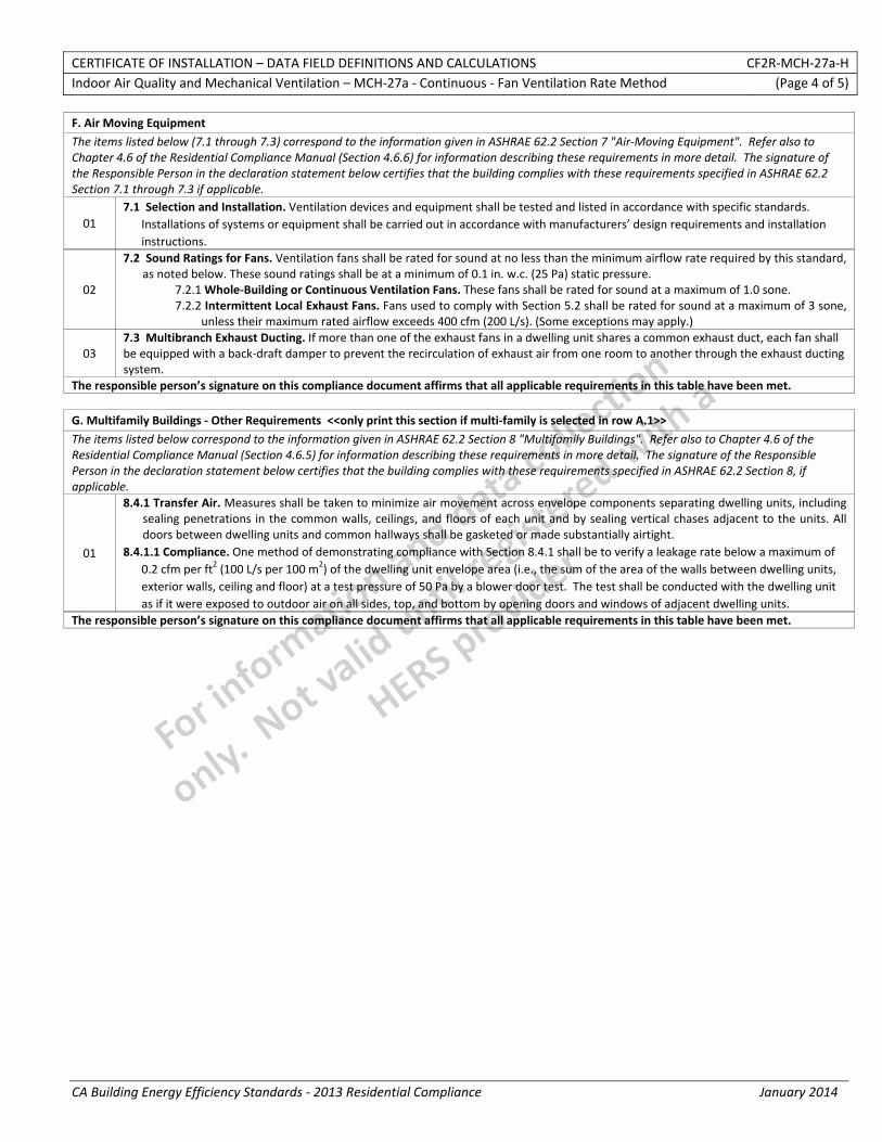
CERTIFICATE OF INSTALLATION – DATA FIELD DEFINITIONS AND CALCULATIONS CF2R‐MCH‐27a‐H Indoor Air Quality and Mechanical Ventilation – MCH‐27a ‐ Continuous ‐ Fan Ventilation Rate Method (Page 4 of 5)
CA Building Energy Efficiency Standards ‐ 2013 Residential Compliance January 2014
F. Air Moving Equipment
The items listed below (7.1 through 7.3) correspond to the information given in ASHRAE 62.2 Section 7 "Air‐Moving Equipment". Refer also to Chapter 4.6 of the Residential Compliance Manual (Section 4.6.6) for information describing these requirements in more detail. The signature of the Responsible Person in the declaration statement below certifies that the building complies with these requirements specified in ASHRAE 62.2 Section 7.1 through 7.3 if applicable.
01 7.1 Selection and Installation. Ventilation devices and equipment shall be tested and listed in accordance with specific standards.
Installations of systems or equipment shall be carried out in accordance with manufacturers’ design requirements and installation instructions.
02
7.2 Sound Ratings for Fans. Ventilation fans shall be rated for sound at no less than the minimum airflow rate required by this standard, as noted below. These sound ratings shall be at a minimum of 0.1 in. w.c. (25 Pa) static pressure.
7.2.1 Whole‐Building or Continuous Ventilation Fans. These fans shall be rated for sound at a maximum of 1.0 sone. 7.2.2 Intermittent Local Exhaust Fans. Fans used to comply with Section 5.2 shall be rated for sound at a maximum of 3 sone,
unless their maximum rated airflow exceeds 400 cfm (200 L/s). (Some exceptions may apply.)
03 7.3 Multibranch Exhaust Ducting. If more than one of the exhaust fans in a dwelling unit shares a common exhaust duct, each fan shall be equipped with a back‐draft damper to prevent the recirculation of exhaust air from one room to another through the exhaust ducting system.
The responsible person’s signature on this compliance document affirms that all applicable requirements in this table have been met.
G. Multifamily Buildings ‐ Other Requirements <<only print this section if multi‐family is selected in row A.1>>
The items listed below correspond to the information given in ASHRAE 62.2 Section 8 "Multifamily Buildings". Refer also to Chapter 4.6 of the Residential Compliance Manual (Section 4.6.5) for information describing these requirements in more detail. The signature of the Responsible Person in the declaration statement below certifies that the building complies with these requirements specified in ASHRAE 62.2 Section 8, if applicable.
01
8.4.1 Transfer Air. Measures shall be taken to minimize air movement across envelope components separating dwelling units, including sealing penetrations in the common walls, ceilings, and floors of each unit and by sealing vertical chases adjacent to the units. All doors between dwelling units and common hallways shall be gasketed or made substantially airtight.
8.4.1.1 Compliance. One method of demonstrating compliance with Section 8.4.1 shall be to verify a leakage rate below a maximum of 0.2 cfm per ft2 (100 L/s per 100 m2) of the dwelling unit envelope area (i.e., the sum of the area of the walls between dwelling units, exterior walls, ceiling and floor) at a test pressure of 50 Pa by a blower door test. The test shall be conducted with the dwelling unit as if it were exposed to outdoor air on all sides, top, and bottom by opening doors and windows of adjacent dwelling units.
The responsible person’s signature on this compliance document affirms that all applicable requirements in this table have been met.
CERTIFICATE OF INSTALLATION – DATA FIELD DEFINITIONS AND CALCULATIONS CF2R‐MCH‐27a‐H Indoor Air Quality and Mechanical Ventilation – MCH‐27a ‐ Continuous ‐ Fan Ventilation Rate Method (Page 5 of 5)
CA Building Energy Efficiency Standards ‐ 2013 Residential Compliance January 2014
DOCUMENTATION AUTHOR'S DECLARATION STATEMENT1. I certify that this Certificate of Installation documentation is accurate and complete.
Documentation Author Name: Documentation Author Signature:
Documentation Author Company Name: Date Signed:
Address: CEA/CEPE/HERS certification identification (If applicable):
City/State/Zip: Phone:
RESPONSIBLE PERSON'S DECLARATION STATEMENT
I certify the following under penalty of perjury, under the laws of the State of California:
1. The information provided on this Certificate of Installation is true and correct.
2. I am eligible under Division 3 of the Business and Professions Code to accept responsibility for the scope of construction or installation, in the applicable classification, for the scope of work specified on this Certificate of Installation (responsible builder/installer), otherwise I am an authorized representative of the responsible builder/installer.
3. The constructed or installed features, materials, components or manufactured devices (the installation) identified on this Certificate of Installation conforms to all applicable codes and regulations, and the installation conforms to the requirements given on the plans and specifications approved by the enforcement agency.
4. I understand that a HERS rater will check the installation to verify compliance, and that if such checking identifies defects; I am required to take corrective action at my expense. I understand that Energy Commission and HERS Provider representatives will also perform quality assurance checking of installations, including those approved as part of a sample group but not checked by a HERS rater, and if those installations fail to meet the requirements of such quality assurance checking, the required corrective action and additional checking/testing of other installations in that HERS sample group will be performed at my expense.
5. I reviewed a copy of the Certificate of Compliance approved by the enforcement agency that identifies the specific requirements for the scope of construction or installation identified on this Certificate of Installation, and I have ensured that the requirements that apply to the construction or installation have been met.
6. I will ensure that a registered copy of this Certificate of Installation shall be posted, or made available with the building permit(s) issued for the building, and made available to the enforcement agency for all applicable inspections. I understand that a registered copy of this Certificate of Installation is required to be included with the documentation the builder provides to the building owner at occupancy.
Responsible Builder/Installer Name: Responsible Builder/Installer Signature:
Company Name: (Installing Subcontractor or General Contractor or Builder/Owner) Position With Company (Title):
Address: CSLB License:
City/State/Zip: Phone Date Signed:
Third Party Quality Control Program (TPQCP) Status: Name of TPQCP (if applicable):
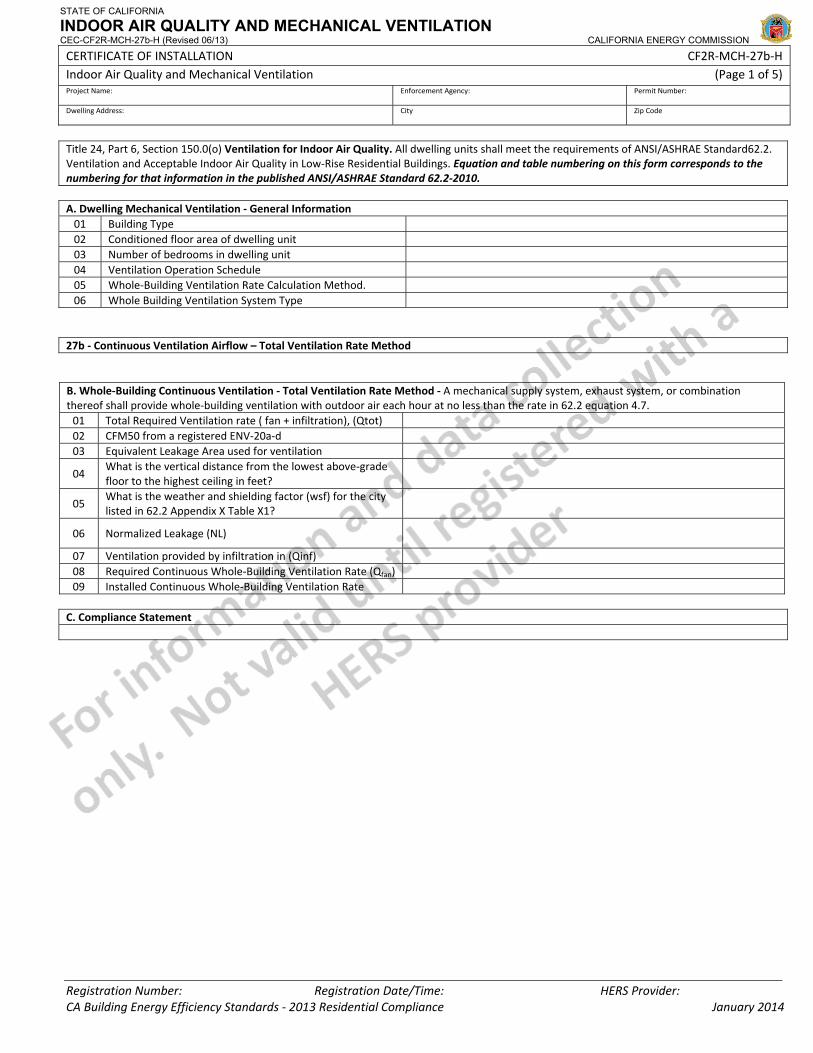
STATE OF CALIFORNIA
INDOOR AIR QUALITY AND MECHANICAL VENTILATION CEC-CF2R-MCH-27b-H (Revised 06/13) CALIFORNIA ENERGY COMMISSION
CERTIFICATE OF INSTALLATION CF2R‐MCH‐27b‐H Indoor Air Quality and Mechanical Ventilation (Page 1 of 5) Project Name: Enforcement Agency: Permit Number:
Dwelling Address: City Zip Code
Registration Number: Registration Date/Time: HERS Provider: CA Building Energy Efficiency Standards ‐ 2013 Residential Compliance January 2014
Title 24, Part 6, Section 150.0(o) Ventilation for Indoor Air Quality. All dwelling units shall meet the requirements of ANSI/ASHRAE Standard62.2. Ventilation and Acceptable Indoor Air Quality in Low‐Rise Residential Buildings. Equation and table numbering on this form corresponds to the numbering for that information in the published ANSI/ASHRAE Standard 62.2‐2010. A. Dwelling Mechanical Ventilation ‐ General Information 01 Building Type 02 Conditioned floor area of dwelling unit 03 Number of bedrooms in dwelling unit 04 Ventilation Operation Schedule 05 Whole‐Building Ventilation Rate Calculation Method. 06 Whole Building Ventilation System Type
27b ‐ Continuous Ventilation Airflow – Total Ventilation Rate Method B. Whole‐Building Continuous Ventilation ‐ Total Ventilation Rate Method ‐ A mechanical supply system, exhaust system, or combination thereof shall provide whole‐building ventilation with outdoor air each hour at no less than the rate in 62.2 equation 4.7. 01 Total Required Ventilation rate ( fan + infiltration), (Qtot) 02 CFM50 from a registered ENV‐20a‐d 03 Equivalent Leakage Area used for ventilation
04 What is the vertical distance from the lowest above‐grade floor to the highest ceiling in feet?
05 What is the weather and shielding factor (wsf) for the city listed in 62.2 Appendix X Table X1?
06 Normalized Leakage (NL)
07 Ventilation provided by infiltration in (Qinf) 08 Required Continuous Whole‐Building Ventilation Rate (Qfan) 09 Installed Continuous Whole‐Building Ventilation Rate
C. Compliance Statement
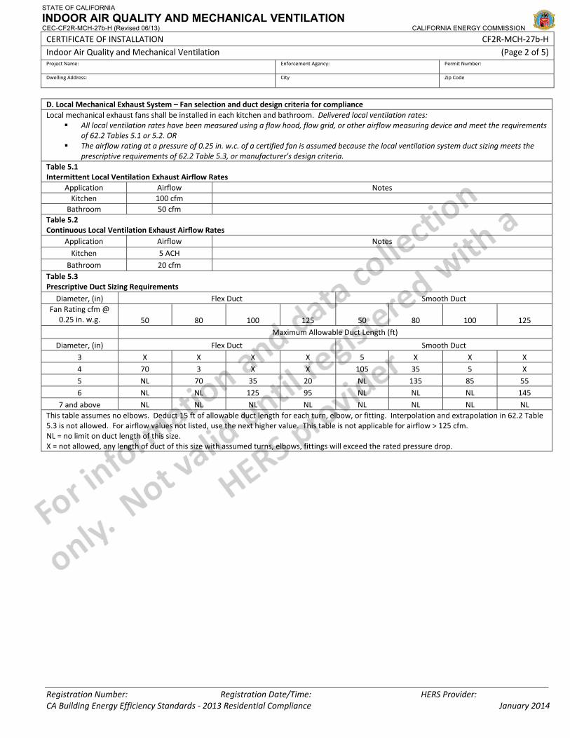
STATE OF CALIFORNIA
INDOOR AIR QUALITY AND MECHANICAL VENTILATION CEC-CF2R-MCH-27b-H (Revised 06/13) CALIFORNIA ENERGY COMMISSION
CERTIFICATE OF INSTALLATION CF2R‐MCH‐27b‐H Indoor Air Quality and Mechanical Ventilation (Page 2 of 5) Project Name: Enforcement Agency: Permit Number:
Dwelling Address: City Zip Code
Registration Number: Registration Date/Time: HERS Provider: CA Building Energy Efficiency Standards ‐ 2013 Residential Compliance January 2014
D. Local Mechanical Exhaust System – Fan selection and duct design criteria for compliance Local mechanical exhaust fans shall be installed in each kitchen and bathroom. Delivered local ventilation rates:
All local ventilation rates have been measured using a flow hood, flow grid, or other airflow measuring device and meet the requirements of 62.2 Tables 5.1 or 5.2. OR
The airflow rating at a pressure of 0.25 in. w.c. of a certified fan is assumed because the local ventilation system duct sizing meets the prescriptive requirements of 62.2 Table 5.3, or manufacturer's design criteria.
Table 5.1 Intermittent Local Ventilation Exhaust Airflow Rates
Application Airflow Notes Kitchen 100 cfm
Bathroom 50 cfm Table 5.2 Continuous Local Ventilation Exhaust Airflow Rates
Application Airflow Notes Kitchen 5 ACH
Bathroom 20 cfm Table 5.3 Prescriptive Duct Sizing Requirements
Diameter, (in) Flex Duct Smooth Duct Fan Rating cfm @
0.25 in. w.g. 50 80 100 125 50 80 100 125 Maximum Allowable Duct Length (ft)
Diameter, (in) Flex Duct Smooth Duct 3 X X X X 5 X X X 4 70 3 X X 105 35 5 X 5 NL 70 35 20 NL 135 85 55 6 NL NL 125 95 NL NL NL 145
7 and above NL NL NL NL NL NL NL NL This table assumes no elbows. Deduct 15 ft of allowable duct length for each turn, elbow, or fitting. Interpolation and extrapolation in 62.2 Table 5.3 is not allowed. For airflow values not listed, use the next higher value. This table is not applicable for airflow > 125 cfm. NL = no limit on duct length of this size. X = not allowed, any length of duct of this size with assumed turns, elbows, fittings will exceed the rated pressure drop.
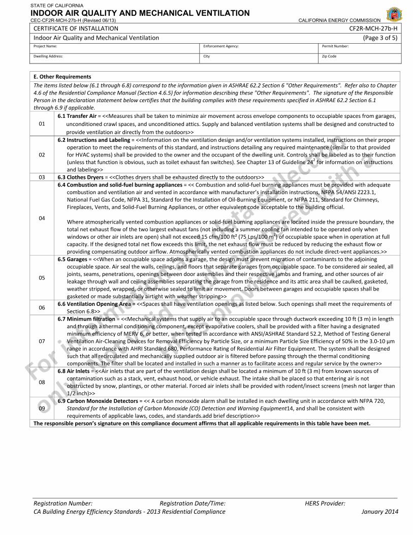
STATE OF CALIFORNIA
INDOOR AIR QUALITY AND MECHANICAL VENTILATION CEC-CF2R-MCH-27b-H (Revised 06/13) CALIFORNIA ENERGY COMMISSION
CERTIFICATE OF INSTALLATION CF2R‐MCH‐27b‐H Indoor Air Quality and Mechanical Ventilation (Page 3 of 5) Project Name: Enforcement Agency: Permit Number:
Dwelling Address: City Zip Code
Registration Number: Registration Date/Time: HERS Provider: CA Building Energy Efficiency Standards ‐ 2013 Residential Compliance January 2014
E. Other Requirements
The items listed below (6.1 through 6.8) correspond to the information given in ASHRAE 62.2 Section 6 "Other Requirements". Refer also to Chapter 4.6 of the Residential Compliance Manual (Section 4.6.5) for information describing these "Other Requirements". The signature of the Responsible Person in the declaration statement below certifies that the building complies with these requirements specified in ASHRAE 62.2 Section 6.1 through 6.9 if applicable.
01 6.1 Transfer Air = <<Measures shall be taken to minimize air movement across envelope components to occupiable spaces from garages,
unconditioned crawl spaces, and unconditioned attics. Supply and balanced ventilation systems shall be designed and constructed to provide ventilation air directly from the outdoors>>
02
6.2 Instructions and Labeling = <<Information on the ventilation design and/or ventilation systems installed, instructions on their proper operation to meet the requirements of this standard, and instructions detailing any required maintenance (similar to that provided for HVAC systems) shall be provided to the owner and the occupant of the dwelling unit. Controls shall be labeled as to their function (unless that function is obvious, such as toilet exhaust fan switches). See Chapter 13 of Guideline 242 for information on instructions and labeling>>
03 6.3 Clothes Dryers = <<Clothes dryers shall be exhausted directly to the outdoors>>
04
6.4 Combustion and solid‐fuel burning appliances = << Combustion and solid‐fuel burning appliances must be provided with adequate combustion and ventilation air and vented in accordance with manufacturer’s installation instructions, NFPA 54/ANSI Z223.1, National Fuel Gas Code, NFPA 31, Standard for the Installation of Oil‐Burning Equipment, or NFPA 211, Standard for Chimneys, Fireplaces, Vents, and Solid‐Fuel Burning Appliances, or other equivalent code acceptable to the building official.
Where atmospherically vented combustion appliances or solid‐fuel burning appliances are located inside the pressure boundary, the total net exhaust flow of the two largest exhaust fans (not including a summer cooling fan intended to be operated only when windows or other air inlets are open) shall not exceed 15 cfm/100 ft² (75 Lps/100 m2) of occupiable space when in operation at full capacity. If the designed total net flow exceeds this limit, the net exhaust flow must be reduced by reducing the exhaust flow or providing compensating outdoor airflow. Atmospherically vented combustion appliances do not include direct‐vent appliances.>>
05
6.5 Garages = <<When an occupiable space adjoins a garage, the design must prevent migration of contaminants to the adjoining occupiable space. Air seal the walls, ceilings, and floors that separate garages from occupiable space. To be considered air sealed, all joints, seams, penetrations, openings between door assemblies and their respective jambs and framing, and other sources of air leakage through wall and ceiling assemblies separating the garage from the residence and its attic area shall be caulked, gasketed, weather stripped, wrapped, or otherwise sealed to limit air movement. Doors between garages and occupiable spaces shall be gasketed or made substantially airtight with weather stripping>>
06 6.6 Ventilation Opening Area = <<Spaces shall have ventilation openings as listed below. Such openings shall meet the requirements of
Section 6.8>>
07
6.7 Minimum filtration = <<Mechanical systems that supply air to an occupiable space through ductwork exceeding 10 ft (3 m) in length and through a thermal conditioning component, except evaporative coolers, shall be provided with a filter having a designated minimum efficiency of MERV 6, or better, when tested in accordance with ANSI/ASHRAE Standard 52.2, Method of Testing General Ventilation Air‐Cleaning Devices for Removal Efficiency by Particle Size, or a minimum Particle Size Efficiency of 50% in the 3.0‐10 µm range in accordance with AHRI Standard 680, Performance Rating of Residential Air Filter Equipment. The system shall be designed such that all recirculated and mechanically supplied outdoor air is filtered before passing through the thermal conditioning components. The filter shall be located and installed in such a manner as to facilitate access and regular service by the owner>>
08
6.8 Air Inlets = <<Air inlets that are part of the ventilation design shall be located a minimum of 10 ft (3 m) from known sources of contamination such as a stack, vent, exhaust hood, or vehicle exhaust. The intake shall be placed so that entering air is not obstructed by snow, plantings, or other material. Forced air inlets shall be provided with rodent/insect screens (mesh not larger than 1/2 inch)>>
09 6.9 Carbon Monoxide Detectors = << A carbon monoxide alarm shall be installed in each dwelling unit in accordance with NFPA 720,
Standard for the Installation of Carbon Monoxide (CO) Detection and Warning Equipment14, and shall be consistent with requirements of applicable laws, codes, and standards.add brief description>>
The responsible person’s signature on this compliance document affirms that all applicable requirements in this table have been met.
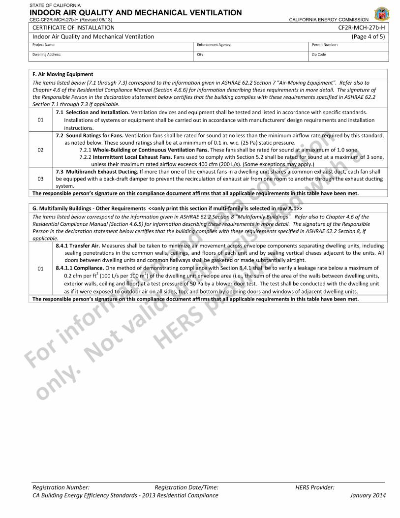
STATE OF CALIFORNIA
INDOOR AIR QUALITY AND MECHANICAL VENTILATION CEC-CF2R-MCH-27b-H (Revised 06/13) CALIFORNIA ENERGY COMMISSION
CERTIFICATE OF INSTALLATION CF2R‐MCH‐27b‐H Indoor Air Quality and Mechanical Ventilation (Page 4 of 5) Project Name: Enforcement Agency: Permit Number:
Dwelling Address: City Zip Code
Registration Number: Registration Date/Time: HERS Provider: CA Building Energy Efficiency Standards ‐ 2013 Residential Compliance January 2014
F. Air Moving Equipment
The items listed below (7.1 through 7.3) correspond to the information given in ASHRAE 62.2 Section 7 "Air‐Moving Equipment". Refer also to Chapter 4.6 of the Residential Compliance Manual (Section 4.6.6) for information describing these requirements in more detail. The signature of the Responsible Person in the declaration statement below certifies that the building complies with these requirements specified in ASHRAE 62.2 Section 7.1 through 7.3 if applicable.
01 7.1 Selection and Installation. Ventilation devices and equipment shall be tested and listed in accordance with specific standards.
Installations of systems or equipment shall be carried out in accordance with manufacturers’ design requirements and installation instructions.
02
7.2 Sound Ratings for Fans. Ventilation fans shall be rated for sound at no less than the minimum airflow rate required by this standard, as noted below. These sound ratings shall be at a minimum of 0.1 in. w.c. (25 Pa) static pressure.
7.2.1 Whole‐Building or Continuous Ventilation Fans. These fans shall be rated for sound at a maximum of 1.0 sone. 7.2.2 Intermittent Local Exhaust Fans. Fans used to comply with Section 5.2 shall be rated for sound at a maximum of 3 sone,
unless their maximum rated airflow exceeds 400 cfm (200 L/s). (Some exceptions may apply.)
03 7.3 Multibranch Exhaust Ducting. If more than one of the exhaust fans in a dwelling unit shares a common exhaust duct, each fan shall be equipped with a back‐draft damper to prevent the recirculation of exhaust air from one room to another through the exhaust ducting system.
The responsible person’s signature on this compliance document affirms that all applicable requirements in this table have been met.
G. Multifamily Buildings ‐ Other Requirements <<only print this section if multi‐family is selected in row A.1>>
The items listed below correspond to the information given in ASHRAE 62.2 Section 8 "Multifamily Buildings". Refer also to Chapter 4.6 of the Residential Compliance Manual (Section 4.6.5) for information describing these requirements in more detail. The signature of the Responsible Person in the declaration statement below certifies that the building complies with these requirements specified in ASHRAE 62.2 Section 8, if applicable.
01
8.4.1 Transfer Air. Measures shall be taken to minimize air movement across envelope components separating dwelling units, including sealing penetrations in the common walls, ceilings, and floors of each unit and by sealing vertical chases adjacent to the units. All doors between dwelling units and common hallways shall be gasketed or made substantially airtight.
8.4.1.1 Compliance. One method of demonstrating compliance with Section 8.4.1 shall be to verify a leakage rate below a maximum of 0.2 cfm per ft2 (100 L/s per 100 m2) of the dwelling unit envelope area (i.e., the sum of the area of the walls between dwelling units, exterior walls, ceiling and floor) at a test pressure of 50 Pa by a blower door test. The test shall be conducted with the dwelling unit as if it were exposed to outdoor air on all sides, top, and bottom by opening doors and windows of adjacent dwelling units.
The responsible person’s signature on this compliance document affirms that all applicable requirements in this table have been met.
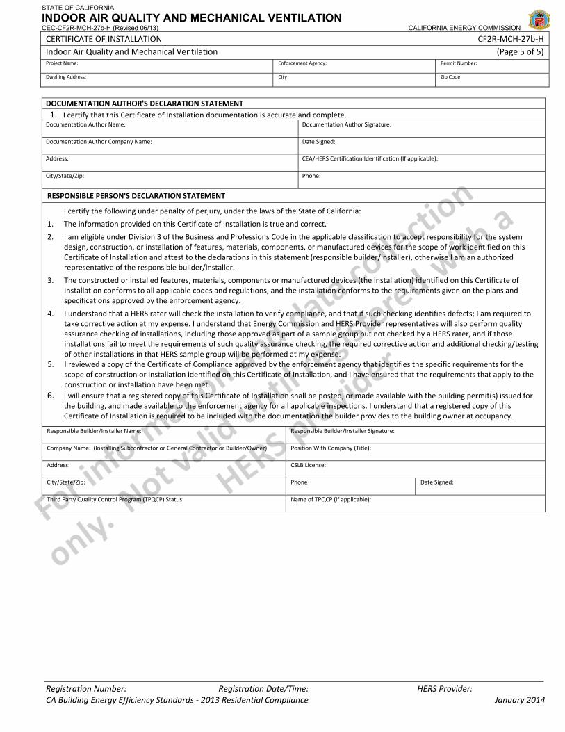
STATE OF CALIFORNIA
INDOOR AIR QUALITY AND MECHANICAL VENTILATION CEC-CF2R-MCH-27b-H (Revised 06/13) CALIFORNIA ENERGY COMMISSION
CERTIFICATE OF INSTALLATION CF2R‐MCH‐27b‐H Indoor Air Quality and Mechanical Ventilation (Page 5 of 5) Project Name: Enforcement Agency: Permit Number:
Dwelling Address: City Zip Code
Registration Number: Registration Date/Time: HERS Provider: CA Building Energy Efficiency Standards ‐ 2013 Residential Compliance January 2014
DOCUMENTATION AUTHOR'S DECLARATION STATEMENT1. I certify that this Certificate of Installation documentation is accurate and complete.
Documentation Author Name: Documentation Author Signature:
Documentation Author Company Name: Date Signed:
Address: CEA/HERS Certification Identification (If applicable):
City/State/Zip: Phone:
RESPONSIBLE PERSON'S DECLARATION STATEMENT
I certify the following under penalty of perjury, under the laws of the State of California:
1. The information provided on this Certificate of Installation is true and correct.
2. I am eligible under Division 3 of the Business and Professions Code in the applicable classification to accept responsibility for the system design, construction, or installation of features, materials, components, or manufactured devices for the scope of work identified on this Certificate of Installation and attest to the declarations in this statement (responsible builder/installer), otherwise I am an authorized representative of the responsible builder/installer.
3. The constructed or installed features, materials, components or manufactured devices (the installation) identified on this Certificate of Installation conforms to all applicable codes and regulations, and the installation conforms to the requirements given on the plans and specifications approved by the enforcement agency.
4. I understand that a HERS rater will check the installation to verify compliance, and that if such checking identifies defects; I am required to take corrective action at my expense. I understand that Energy Commission and HERS Provider representatives will also perform quality assurance checking of installations, including those approved as part of a sample group but not checked by a HERS rater, and if those installations fail to meet the requirements of such quality assurance checking, the required corrective action and additional checking/testing of other installations in that HERS sample group will be performed at my expense.
5. I reviewed a copy of the Certificate of Compliance approved by the enforcement agency that identifies the specific requirements for the scope of construction or installation identified on this Certificate of Installation, and I have ensured that the requirements that apply to the construction or installation have been met.
6. I will ensure that a registered copy of this Certificate of Installation shall be posted, or made available with the building permit(s) issued for the building, and made available to the enforcement agency for all applicable inspections. I understand that a registered copy of this Certificate of Installation is required to be included with the documentation the builder provides to the building owner at occupancy.
Responsible Builder/Installer Name: Responsible Builder/Installer Signature:
Company Name: (Installing Subcontractor or General Contractor or Builder/Owner) Position With Company (Title):
Address: CSLB License:
City/State/Zip: Phone Date Signed:
Third Party Quality Control Program (TPQCP) Status: Name of TPQCP (if applicable):
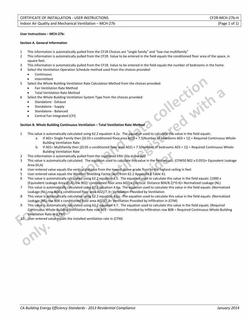
CERTIFICATE OF INSTALLATION ‐ USER INSTRUCTIONS CF2R‐MCH‐27b‐H Indoor Air Quality and Mechanical Ventilation – MCH‐27b (Page 1 of 1)
CA Building Energy Efficiency Standards ‐ 2013 Residential Compliance January 2014
User Instructions – MCH‐27b: Section A. General Information 1 This information is automatically pulled from the CF1R Choices are “single family” and “low‐rise multifamily” 2 This information is automatically pulled from the CF1R. Value to be entered in the field equals the conditioned floor area of the space, in
square feet. 3 This information is automatically pulled from the CF1R. Value to be entered in the field equals the number of bedrooms in the home. 4 Select the Ventilation Operation Schedule method used from the choices provided:
• Continuous • Intermittent
5 Select the Whole Building Ventilation Rate Calculation Method from the choices provided: • Fan Ventilation Rate Method • Total Ventilation Rate Method
6 Select the Whole Building Ventilation System Type from the choices provided: • Standalone ‐ Exhaust • Standalone ‐ Supply • Standalone ‐ Balanced • Central Fan Integrated (CFI)
Section B. Whole Building Continuous Ventilation – Total Ventilation Rate Method 1 This value is automatically calculated using 62.2 equation 4.2a. The equation used to calculate this value in the field equals:
a. If A01= Single Family then [(0.03 x conditioned floor area A02) + 7.5(Number of bedrooms A03 + 1)] = Required Continuous Whole‐Building Ventilation Rate
b. If A01= Multifamily then [(0.05 x conditioned floor area A02) + 7.5(Number of bedrooms A03 + 1)] = Required Continuous Whole‐Building Ventilation Rate
2 This information is automatically pulled from the registered ENV‐20a‐d row A02 3 This value is automatically calculated. The equation used to calculate this value in the field equals: (CFM50 B02 x 0.055)= Equivalent Leakage
Area (ELA) 4 User entered value equals the vertical distance from the lowest above‐grade floor to the highest ceiling in feet 5 User entered value equals the Weather Shielding Factor (wsf) from 62.2 Appendix X Table X1. 6 This value is automatically calculated using 62.2 equation 4.5. The equation used to calculate this value in the field equals: [1000 x
(Equivalent Leakage Area (ELA) row B02/ conditioned floor area A02) x (Vertical Distance B04/8.2)^0.4]= Normalized Leakage (NL) 7 This value is automatically calculated using 62.2 equation 4.6a. The equation used to calculate this value in the field equals: (Normalized
Leakage (NL) row B06 x conditioned floor area A02)/7.3= Ventilation Provided by Ventilation 8 This value is automatically calculated using 62.2 equation 4.6a. The equation used to calculate this value in the field equals: (Normalized
Leakage (NL) row B06 x conditioned floor area A02)/7.3= Ventilation Provided by Infiltration in (CFM) 9 This value is automatically calculated using 62.2 equation 4.7. The equation used to calculate this value in the field equals: (Required
Continuous Whole‐Building Ventilation Rate row B01 ‐ Ventilation Provided by Infiltration row B08 = Required Continuous Whole‐Building Ventilation Rate in (CFM)
10 User entered value equals the installed ventilation rate in (CFM)
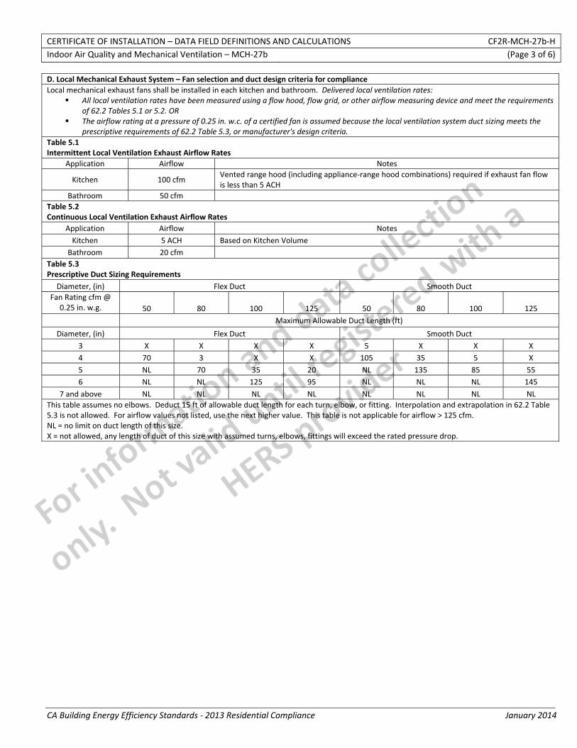
CERTIFICATE OF INSTALLATION – DATA FIELD DEFINITIONS AND CALCULATIONS CF2R‐MCH‐27b‐H Indoor Air Quality and Mechanical Ventilation – MCH‐27b (Page 3 of 6)
CA Building Energy Efficiency Standards ‐ 2013 Residential Compliance January 2014
D. Local Mechanical Exhaust System – Fan selection and duct design criteria for compliance Local mechanical exhaust fans shall be installed in each kitchen and bathroom. Delivered local ventilation rates:
All local ventilation rates have been measured using a flow hood, flow grid, or other airflow measuring device and meet the requirements of 62.2 Tables 5.1 or 5.2. OR
The airflow rating at a pressure of 0.25 in. w.c. of a certified fan is assumed because the local ventilation system duct sizing meets the prescriptive requirements of 62.2 Table 5.3, or manufacturer's design criteria.
Table 5.1 Intermittent Local Ventilation Exhaust Airflow Rates
Application Airflow Notes
Kitchen 100 cfm Vented range hood (including appliance‐range hood combinations) required if exhaust fan flow is less than 5 ACH
Bathroom 50 cfm Table 5.2 Continuous Local Ventilation Exhaust Airflow Rates
Application Airflow Notes Kitchen 5 ACH Based on Kitchen Volume
Bathroom 20 cfm Table 5.3 Prescriptive Duct Sizing Requirements
Diameter, (in) Flex Duct Smooth Duct Fan Rating cfm @
0.25 in. w.g. 50 80 100 125 50 80 100 125 Maximum Allowable Duct Length (ft)
Diameter, (in) Flex Duct Smooth Duct 3 X X X X 5 X X X 4 70 3 X X 105 35 5 X 5 NL 70 35 20 NL 135 85 55 6 NL NL 125 95 NL NL NL 145
7 and above NL NL NL NL NL NL NL NL This table assumes no elbows. Deduct 15 ft of allowable duct length for each turn, elbow, or fitting. Interpolation and extrapolation in 62.2 Table 5.3 is not allowed. For airflow values not listed, use the next higher value. This table is not applicable for airflow > 125 cfm. NL = no limit on duct length of this size. X = not allowed, any length of duct of this size with assumed turns, elbows, fittings will exceed the rated pressure drop.
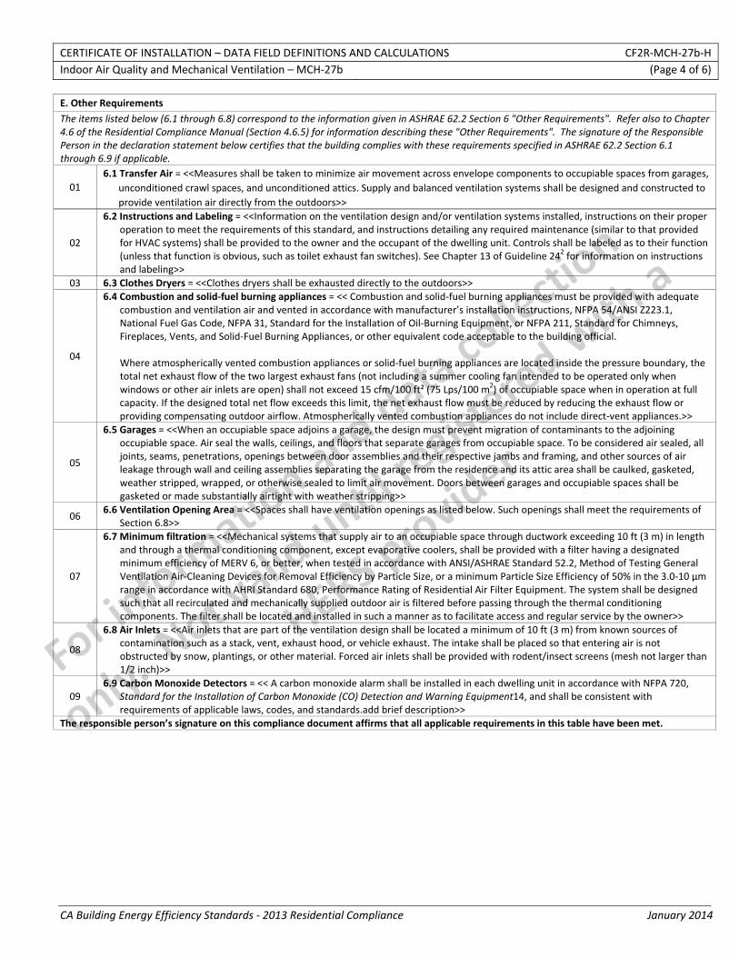
CERTIFICATE OF INSTALLATION – DATA FIELD DEFINITIONS AND CALCULATIONS CF2R‐MCH‐27b‐H Indoor Air Quality and Mechanical Ventilation – MCH‐27b (Page 4 of 6)
CA Building Energy Efficiency Standards ‐ 2013 Residential Compliance January 2014
E. Other Requirements
The items listed below (6.1 through 6.8) correspond to the information given in ASHRAE 62.2 Section 6 "Other Requirements". Refer also to Chapter 4.6 of the Residential Compliance Manual (Section 4.6.5) for information describing these "Other Requirements". The signature of the Responsible Person in the declaration statement below certifies that the building complies with these requirements specified in ASHRAE 62.2 Section 6.1 through 6.9 if applicable.
01 6.1 Transfer Air = <<Measures shall be taken to minimize air movement across envelope components to occupiable spaces from garages,
unconditioned crawl spaces, and unconditioned attics. Supply and balanced ventilation systems shall be designed and constructed to provide ventilation air directly from the outdoors>>
02
6.2 Instructions and Labeling = <<Information on the ventilation design and/or ventilation systems installed, instructions on their proper operation to meet the requirements of this standard, and instructions detailing any required maintenance (similar to that provided for HVAC systems) shall be provided to the owner and the occupant of the dwelling unit. Controls shall be labeled as to their function (unless that function is obvious, such as toilet exhaust fan switches). See Chapter 13 of Guideline 242 for information on instructions and labeling>>
03 6.3 Clothes Dryers = <<Clothes dryers shall be exhausted directly to the outdoors>>
04
6.4 Combustion and solid‐fuel burning appliances = << Combustion and solid‐fuel burning appliances must be provided with adequate combustion and ventilation air and vented in accordance with manufacturer’s installation instructions, NFPA 54/ANSI Z223.1, National Fuel Gas Code, NFPA 31, Standard for the Installation of Oil‐Burning Equipment, or NFPA 211, Standard for Chimneys, Fireplaces, Vents, and Solid‐Fuel Burning Appliances, or other equivalent code acceptable to the building official.
Where atmospherically vented combustion appliances or solid‐fuel burning appliances are located inside the pressure boundary, the total net exhaust flow of the two largest exhaust fans (not including a summer cooling fan intended to be operated only when windows or other air inlets are open) shall not exceed 15 cfm/100 ft² (75 Lps/100 m2) of occupiable space when in operation at full capacity. If the designed total net flow exceeds this limit, the net exhaust flow must be reduced by reducing the exhaust flow or providing compensating outdoor airflow. Atmospherically vented combustion appliances do not include direct‐vent appliances.>>
05
6.5 Garages = <<When an occupiable space adjoins a garage, the design must prevent migration of contaminants to the adjoining occupiable space. Air seal the walls, ceilings, and floors that separate garages from occupiable space. To be considered air sealed, all joints, seams, penetrations, openings between door assemblies and their respective jambs and framing, and other sources of air leakage through wall and ceiling assemblies separating the garage from the residence and its attic area shall be caulked, gasketed, weather stripped, wrapped, or otherwise sealed to limit air movement. Doors between garages and occupiable spaces shall be gasketed or made substantially airtight with weather stripping>>
06 6.6 Ventilation Opening Area = <<Spaces shall have ventilation openings as listed below. Such openings shall meet the requirements of
Section 6.8>>
07
6.7 Minimum filtration = <<Mechanical systems that supply air to an occupiable space through ductwork exceeding 10 ft (3 m) in length and through a thermal conditioning component, except evaporative coolers, shall be provided with a filter having a designated minimum efficiency of MERV 6, or better, when tested in accordance with ANSI/ASHRAE Standard 52.2, Method of Testing General Ventilation Air‐Cleaning Devices for Removal Efficiency by Particle Size, or a minimum Particle Size Efficiency of 50% in the 3.0‐10 µm range in accordance with AHRI Standard 680, Performance Rating of Residential Air Filter Equipment. The system shall be designed such that all recirculated and mechanically supplied outdoor air is filtered before passing through the thermal conditioning components. The filter shall be located and installed in such a manner as to facilitate access and regular service by the owner>>
08
6.8 Air Inlets = <<Air inlets that are part of the ventilation design shall be located a minimum of 10 ft (3 m) from known sources of contamination such as a stack, vent, exhaust hood, or vehicle exhaust. The intake shall be placed so that entering air is not obstructed by snow, plantings, or other material. Forced air inlets shall be provided with rodent/insect screens (mesh not larger than 1/2 inch)>>
09 6.9 Carbon Monoxide Detectors = << A carbon monoxide alarm shall be installed in each dwelling unit in accordance with NFPA 720,
Standard for the Installation of Carbon Monoxide (CO) Detection and Warning Equipment14, and shall be consistent with requirements of applicable laws, codes, and standards.add brief description>>
The responsible person’s signature on this compliance document affirms that all applicable requirements in this table have been met.
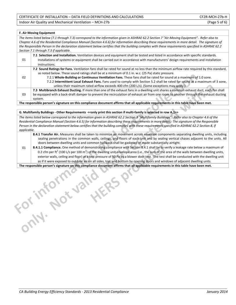
CERTIFICATE OF INSTALLATION – DATA FIELD DEFINITIONS AND CALCULATIONS CF2R‐MCH‐27b‐H Indoor Air Quality and Mechanical Ventilation – MCH‐27b (Page 5 of 6)
CA Building Energy Efficiency Standards ‐ 2013 Residential Compliance January 2014
F. Air Moving Equipment
The items listed below (7.1 through 7.3) correspond to the information given in ASHRAE 62.2 Section 7 "Air‐Moving Equipment". Refer also to Chapter 4.6 of the Residential Compliance Manual (Section 4.6.6) for information describing these requirements in more detail. The signature of the Responsible Person in the declaration statement below certifies that the building complies with these requirements specified in ASHRAE 62.2 Section 7.1 through 7.3 if applicable.
01 7.1 Selection and Installation. Ventilation devices and equipment shall be tested and listed in accordance with specific standards.
Installations of systems or equipment shall be carried out in accordance with manufacturers’ design requirements and installation instructions.
02
7.2 Sound Ratings for Fans. Ventilation fans shall be rated for sound at no less than the minimum airflow rate required by this standard, as noted below. These sound ratings shall be at a minimum of 0.1 in. w.c. (25 Pa) static pressure.
7.2.1 Whole‐Building or Continuous Ventilation Fans. These fans shall be rated for sound at a maximum of 1.0 sone. 7.2.2 Intermittent Local Exhaust Fans. Fans used to comply with Section 5.2 shall be rated for sound at a maximum of 3 sone,
unless their maximum rated airflow exceeds 400 cfm (200 L/s). (Some exceptions may apply.)
03 7.3 Multibranch Exhaust Ducting. If more than one of the exhaust fans in a dwelling unit shares a common exhaust duct, each fan shall be equipped with a back‐draft damper to prevent the recirculation of exhaust air from one room to another through the exhaust ducting system.
The responsible person’s signature on this compliance document affirms that all applicable requirements in this table have been met.
G. Multifamily Buildings ‐ Other Requirements <<only print this section if multi‐family is selected in row A.1>>
The items listed below correspond to the information given in ASHRAE 62.2 Section 8 "Multifamily Buildings". Refer also to Chapter 4.6 of the Residential Compliance Manual (Section 4.6.5) for information describing these requirements in more detail. The signature of the Responsible Person in the declaration statement below certifies that the building complies with these requirements specified in ASHRAE 62.2 Section 8, if applicable.
01
8.4.1 Transfer Air. Measures shall be taken to minimize air movement across envelope components separating dwelling units, including sealing penetrations in the common walls, ceilings, and floors of each unit and by sealing vertical chases adjacent to the units. All doors between dwelling units and common hallways shall be gasketed or made substantially airtight.
8.4.1.1 Compliance. One method of demonstrating compliance with Section 8.4.1 shall be to verify a leakage rate below a maximum of 0.2 cfm per ft2 (100 L/s per 100 m2) of the dwelling unit envelope area (i.e., the sum of the area of the walls between dwelling units, exterior walls, ceiling and floor) at a test pressure of 50 Pa by a blower door test. The test shall be conducted with the dwelling unit as if it were exposed to outdoor air on all sides, top, and bottom by opening doors and windows of adjacent dwelling units.
The responsible person’s signature on this compliance document affirms that all applicable requirements in this table have been met.
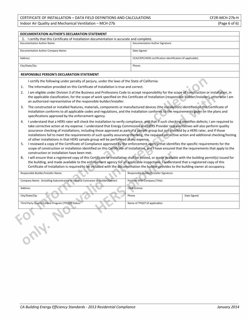
CERTIFICATE OF INSTALLATION – DATA FIELD DEFINITIONS AND CALCULATIONS CF2R‐MCH‐27b‐H Indoor Air Quality and Mechanical Ventilation – MCH‐27b (Page 6 of 6)
CA Building Energy Efficiency Standards ‐ 2013 Residential Compliance January 2014
DOCUMENTATION AUTHOR'S DECLARATION STATEMENT1. I certify that this Certificate of Installation documentation is accurate and complete.
Documentation Author Name: Documentation Author Signature:
Documentation Author Company Name: Date Signed:
Address: CEA/CEPE/HERS certification identification (If applicable):
City/State/Zip: Phone:
RESPONSIBLE PERSON'S DECLARATION STATEMENT
I certify the following under penalty of perjury, under the laws of the State of California:
1. The information provided on this Certificate of Installation is true and correct.
2. I am eligible under Division 3 of the Business and Professions Code to accept responsibility for the scope of construction or installation, in the applicable classification, for the scope of work specified on this Certificate of Installation (responsible builder/installer), otherwise I am an authorized representative of the responsible builder/installer.
3. The constructed or installed features, materials, components or manufactured devices (the installation) identified on this Certificate of Installation conforms to all applicable codes and regulations, and the installation conforms to the requirements given on the plans and specifications approved by the enforcement agency.
4. I understand that a HERS rater will check the installation to verify compliance, and that if such checking identifies defects; I am required to take corrective action at my expense. I understand that Energy Commission and HERS Provider representatives will also perform quality assurance checking of installations, including those approved as part of a sample group but not checked by a HERS rater, and if those installations fail to meet the requirements of such quality assurance checking, the required corrective action and additional checking/testing of other installations in that HERS sample group will be performed at my expense.
5. I reviewed a copy of the Certificate of Compliance approved by the enforcement agency that identifies the specific requirements for the scope of construction or installation identified on this Certificate of Installation, and I have ensured that the requirements that apply to the construction or installation have been met.
6. I will ensure that a registered copy of this Certificate of Installation shall be posted, or made available with the building permit(s) issued for the building, and made available to the enforcement agency for all applicable inspections. I understand that a registered copy of this Certificate of Installation is required to be included with the documentation the builder provides to the building owner at occupancy.
Responsible Builder/Installer Name: Responsible Builder/Installer Signature:
Company Name: (Installing Subcontractor or General Contractor or Builder/Owner) Position With Company (Title):
Address: CSLB License:
City/State/Zip: Phone Date Signed:
Third Party Quality Control Program (TPQCP) Status: Name of TPQCP (if applicable):
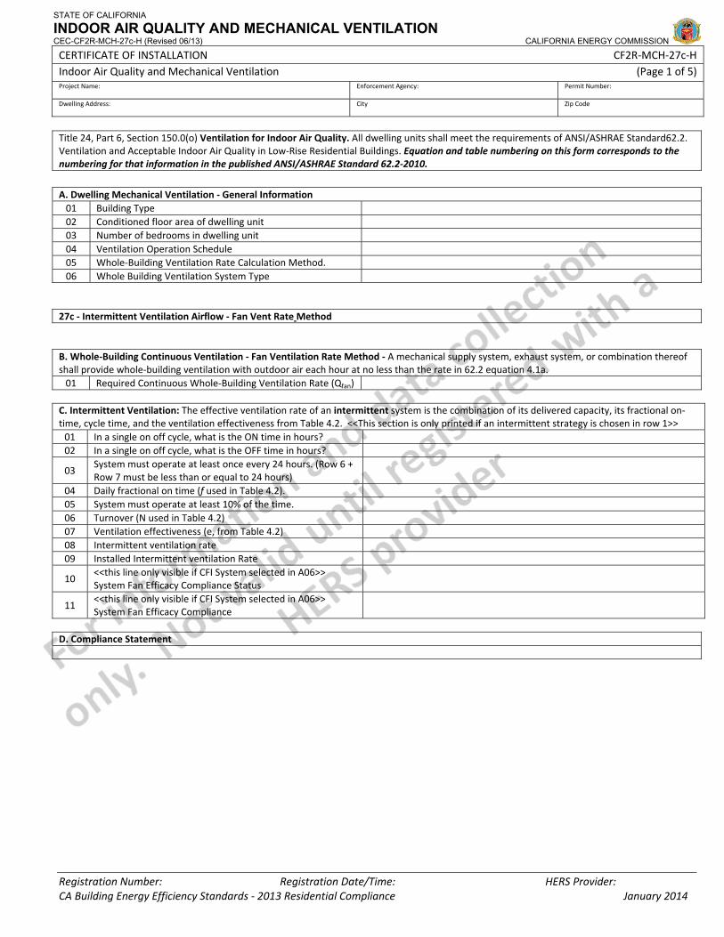
STATE OF CALIFORNIA
INDOOR AIR QUALITY AND MECHANICAL VENTILATION CEC-CF2R-MCH-27c-H (Revised 06/13) CALIFORNIA ENERGY COMMISSION
CERTIFICATE OF INSTALLATION CF2R‐MCH‐27c‐H Indoor Air Quality and Mechanical Ventilation (Page 1 of 5) Project Name: Enforcement Agency: Permit Number:
Dwelling Address: City Zip Code
Registration Number: Registration Date/Time: HERS Provider: CA Building Energy Efficiency Standards ‐ 2013 Residential Compliance January 2014
Title 24, Part 6, Section 150.0(o) Ventilation for Indoor Air Quality. All dwelling units shall meet the requirements of ANSI/ASHRAE Standard62.2. Ventilation and Acceptable Indoor Air Quality in Low‐Rise Residential Buildings. Equation and table numbering on this form corresponds to the numbering for that information in the published ANSI/ASHRAE Standard 62.2‐2010.
A. Dwelling Mechanical Ventilation ‐ General Information 01 Building Type 02 Conditioned floor area of dwelling unit 03 Number of bedrooms in dwelling unit 04 Ventilation Operation Schedule 05 Whole‐Building Ventilation Rate Calculation Method. 06 Whole Building Ventilation System Type
27c ‐ Intermittent Ventilation Airflow ‐ Fan Vent Rate Method B. Whole‐Building Continuous Ventilation ‐ Fan Ventilation Rate Method ‐ A mechanical supply system, exhaust system, or combination thereof shall provide whole‐building ventilation with outdoor air each hour at no less than the rate in 62.2 equation 4.1a. 01 Required Continuous Whole‐Building Ventilation Rate (Qfan)
C. Intermittent Ventilation: The effective ventilation rate of an intermittent system is the combination of its delivered capacity, its fractional on‐time, cycle time, and the ventilation effectiveness from Table 4.2. <<This section is only printed if an intermittent strategy is chosen in row 1>> 01 In a single on off cycle, what is the ON time in hours? 02 In a single on off cycle, what is the OFF time in hours?
03 System must operate at least once every 24 hours. (Row 6 + Row 7 must be less than or equal to 24 hours)
04 Daily fractional on time (f used in Table 4.2). 05 System must operate at least 10% of the time. 06 Turnover (N used in Table 4.2) 07 Ventilation effectiveness (e, from Table 4.2) 08 Intermittent ventilation rate 09 Installed Intermittent ventilation Rate
10 <<this line only visible if CFI System selected in A06>> System Fan Efficacy Compliance Status
11 <<this line only visible if CFI System selected in A06>> System Fan Efficacy Compliance
D. Compliance Statement
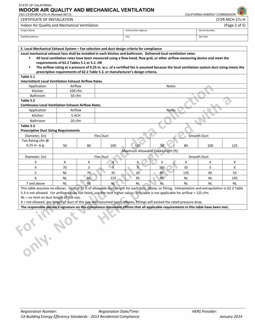
STATE OF CALIFORNIA
INDOOR AIR QUALITY AND MECHANICAL VENTILATION CEC-CF2R-MCH-27c-H (Revised 06/13) CALIFORNIA ENERGY COMMISSION
CERTIFICATE OF INSTALLATION CF2R‐MCH‐27c‐H Indoor Air Quality and Mechanical Ventilation (Page 2 of 5) Project Name: Enforcement Agency: Permit Number:
Dwelling Address: City Zip Code
Registration Number: Registration Date/Time: HERS Provider: CA Building Energy Efficiency Standards ‐ 2013 Residential Compliance January 2014
E. Local Mechanical Exhaust System – Fan selection and duct design criteria for compliance Local mechanical exhaust fans shall be installed in each kitchen and bathroom. Delivered local ventilation rates:
All local ventilation rates have been measured using a flow hood, flow grid, or other airflow measuring device and meet the requirements of 62.2 Tables 5.1 or 5.2. OR
The airflow rating at a pressure of 0.25 in. w.c. of a certified fan is assumed because the local ventilation system duct sizing meets the prescriptive requirements of 62.2 Table 5.3, or manufacturer's design criteria.
Table 5.1 Intermittent Local Ventilation Exhaust Airflow Rates
Application Airflow Notes Kitchen 100 cfm
Bathroom 50 cfm Table 5.2 Continuous Local Ventilation Exhaust Airflow Rates
Application Airflow Notes Kitchen 5 ACH
Bathroom 20 cfm Table 5.3 Prescriptive Duct Sizing Requirements
Diameter, (in) Flex Duct Smooth Duct Fan Rating cfm @
0.25 in. w.g. 50 80 100 125 50 80 100 125 Maximum Allowable Duct Length (ft)
Diameter, (in) Flex Duct Smooth Duct 3 X X X X 5 X X X 4 70 3 X X 105 35 5 X 5 NL 70 35 20 NL 135 85 55 6 NL NL 125 95 NL NL NL 145
7 and above NL NL NL NL NL NL NL NL This table assumes no elbows. Deduct 15 ft of allowable duct length for each turn, elbow, or fitting. Interpolation and extrapolation in 62.2 Table 5.3 is not allowed. For airflow values not listed, use the next higher value. This table is not applicable for airflow > 125 cfm. NL = no limit on duct length of this size. X = not allowed, any length of duct of this size with assumed turns, elbows, fittings will exceed the rated pressure drop. The responsible person’s signature on this compliance document affirms that all applicable requirements in this table have been met.
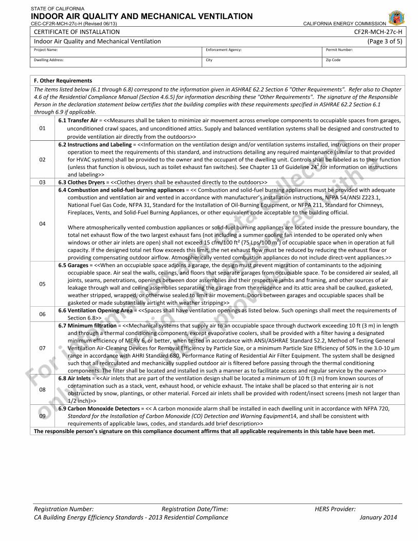
STATE OF CALIFORNIA
INDOOR AIR QUALITY AND MECHANICAL VENTILATION CEC-CF2R-MCH-27c-H (Revised 06/13) CALIFORNIA ENERGY COMMISSION
CERTIFICATE OF INSTALLATION CF2R‐MCH‐27c‐H Indoor Air Quality and Mechanical Ventilation (Page 3 of 5) Project Name: Enforcement Agency: Permit Number:
Dwelling Address: City Zip Code
Registration Number: Registration Date/Time: HERS Provider: CA Building Energy Efficiency Standards ‐ 2013 Residential Compliance January 2014
F. Other Requirements
The items listed below (6.1 through 6.8) correspond to the information given in ASHRAE 62.2 Section 6 "Other Requirements". Refer also to Chapter 4.6 of the Residential Compliance Manual (Section 4.6.5) for information describing these "Other Requirements". The signature of the Responsible Person in the declaration statement below certifies that the building complies with these requirements specified in ASHRAE 62.2 Section 6.1 through 6.9 if applicable.
01 6.1 Transfer Air = <<Measures shall be taken to minimize air movement across envelope components to occupiable spaces from garages,
unconditioned crawl spaces, and unconditioned attics. Supply and balanced ventilation systems shall be designed and constructed to provide ventilation air directly from the outdoors>>
02
6.2 Instructions and Labeling = <<Information on the ventilation design and/or ventilation systems installed, instructions on their proper operation to meet the requirements of this standard, and instructions detailing any required maintenance (similar to that provided for HVAC systems) shall be provided to the owner and the occupant of the dwelling unit. Controls shall be labeled as to their function (unless that function is obvious, such as toilet exhaust fan switches). See Chapter 13 of Guideline 242 for information on instructions and labeling>>
03 6.3 Clothes Dryers = <<Clothes dryers shall be exhausted directly to the outdoors>>
04
6.4 Combustion and solid‐fuel burning appliances = << Combustion and solid‐fuel burning appliances must be provided with adequate combustion and ventilation air and vented in accordance with manufacturer’s installation instructions, NFPA 54/ANSI Z223.1, National Fuel Gas Code, NFPA 31, Standard for the Installation of Oil‐Burning Equipment, or NFPA 211, Standard for Chimneys, Fireplaces, Vents, and Solid‐Fuel Burning Appliances, or other equivalent code acceptable to the building official.
Where atmospherically vented combustion appliances or solid‐fuel burning appliances are located inside the pressure boundary, the total net exhaust flow of the two largest exhaust fans (not including a summer cooling fan intended to be operated only when windows or other air inlets are open) shall not exceed 15 cfm/100 ft² (75 Lps/100 m2) of occupiable space when in operation at full capacity. If the designed total net flow exceeds this limit, the net exhaust flow must be reduced by reducing the exhaust flow or providing compensating outdoor airflow. Atmospherically vented combustion appliances do not include direct‐vent appliances.>>
05
6.5 Garages = <<When an occupiable space adjoins a garage, the design must prevent migration of contaminants to the adjoining occupiable space. Air seal the walls, ceilings, and floors that separate garages from occupiable space. To be considered air sealed, all joints, seams, penetrations, openings between door assemblies and their respective jambs and framing, and other sources of air leakage through wall and ceiling assemblies separating the garage from the residence and its attic area shall be caulked, gasketed, weather stripped, wrapped, or otherwise sealed to limit air movement. Doors between garages and occupiable spaces shall be gasketed or made substantially airtight with weather stripping>>
06 6.6 Ventilation Opening Area = <<Spaces shall have ventilation openings as listed below. Such openings shall meet the requirements of
Section 6.8>>
07
6.7 Minimum filtration = <<Mechanical systems that supply air to an occupiable space through ductwork exceeding 10 ft (3 m) in length and through a thermal conditioning component, except evaporative coolers, shall be provided with a filter having a designated minimum efficiency of MERV 6, or better, when tested in accordance with ANSI/ASHRAE Standard 52.2, Method of Testing General Ventilation Air‐Cleaning Devices for Removal Efficiency by Particle Size, or a minimum Particle Size Efficiency of 50% in the 3.0‐10 µm range in accordance with AHRI Standard 680, Performance Rating of Residential Air Filter Equipment. The system shall be designed such that all recirculated and mechanically supplied outdoor air is filtered before passing through the thermal conditioning components. The filter shall be located and installed in such a manner as to facilitate access and regular service by the owner>>
08
6.8 Air Inlets = <<Air inlets that are part of the ventilation design shall be located a minimum of 10 ft (3 m) from known sources of contamination such as a stack, vent, exhaust hood, or vehicle exhaust. The intake shall be placed so that entering air is not obstructed by snow, plantings, or other material. Forced air inlets shall be provided with rodent/insect screens (mesh not larger than 1/2 inch)>>
09 6.9 Carbon Monoxide Detectors = << A carbon monoxide alarm shall be installed in each dwelling unit in accordance with NFPA 720,
Standard for the Installation of Carbon Monoxide (CO) Detection and Warning Equipment14, and shall be consistent with requirements of applicable laws, codes, and standards.add brief description>>
The responsible person’s signature on this compliance document affirms that all applicable requirements in this table have been met.
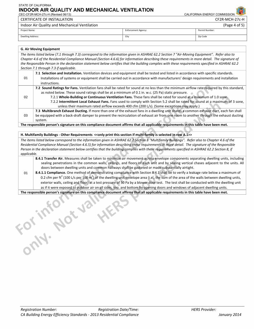
STATE OF CALIFORNIA
INDOOR AIR QUALITY AND MECHANICAL VENTILATION CEC-CF2R-MCH-27c-H (Revised 06/13) CALIFORNIA ENERGY COMMISSION
CERTIFICATE OF INSTALLATION CF2R‐MCH‐27c‐H Indoor Air Quality and Mechanical Ventilation (Page 4 of 5) Project Name: Enforcement Agency: Permit Number:
Dwelling Address: City Zip Code
Registration Number: Registration Date/Time: HERS Provider: CA Building Energy Efficiency Standards ‐ 2013 Residential Compliance January 2014
G. Air Moving Equipment
The items listed below (7.1 through 7.3) correspond to the information given in ASHRAE 62.2 Section 7 "Air‐Moving Equipment". Refer also to Chapter 4.6 of the Residential Compliance Manual (Section 4.6.6) for information describing these requirements in more detail. The signature of the Responsible Person in the declaration statement below certifies that the building complies with these requirements specified in ASHRAE 62.2 Section 7.1 through 7.3 if applicable.
01 7.1 Selection and Installation. Ventilation devices and equipment shall be tested and listed in accordance with specific standards.
Installations of systems or equipment shall be carried out in accordance with manufacturers’ design requirements and installation instructions.
02
7.2 Sound Ratings for Fans. Ventilation fans shall be rated for sound at no less than the minimum airflow rate required by this standard, as noted below. These sound ratings shall be at a minimum of 0.1 in. w.c. (25 Pa) static pressure.
7.2.1 Whole‐Building or Continuous Ventilation Fans. These fans shall be rated for sound at a maximum of 1.0 sone. 7.2.2 Intermittent Local Exhaust Fans. Fans used to comply with Section 5.2 shall be rated for sound at a maximum of 3 sone,
unless their maximum rated airflow exceeds 400 cfm (200 L/s). (Some exceptions may apply.)
03 7.3 Multibranch Exhaust Ducting. If more than one of the exhaust fans in a dwelling unit shares a common exhaust duct, each fan shall be equipped with a back‐draft damper to prevent the recirculation of exhaust air from one room to another through the exhaust ducting system.
The responsible person’s signature on this compliance document affirms that all applicable requirements in this table have been met.
H. Multifamily Buildings ‐ Other Requirements <<only print this section if multi‐family is selected in row A.1>>
The items listed below correspond to the information given in ASHRAE 62.2 Section 8 "Multifamily Buildings". Refer also to Chapter 4.6 of the Residential Compliance Manual (Section 4.6.5) for information describing these requirements in more detail. The signature of the Responsible Person in the declaration statement below certifies that the building complies with these requirements specified in ASHRAE 62.2 Section 8, if applicable.
01
8.4.1 Transfer Air. Measures shall be taken to minimize air movement across envelope components separating dwelling units, including sealing penetrations in the common walls, ceilings, and floors of each unit and by sealing vertical chases adjacent to the units. All doors between dwelling units and common hallways shall be gasketed or made substantially airtight.
8.4.1.1 Compliance. One method of demonstrating compliance with Section 8.4.1 shall be to verify a leakage rate below a maximum of 0.2 cfm per ft2 (100 L/s per 100 m2) of the dwelling unit envelope area (i.e., the sum of the area of the walls between dwelling units, exterior walls, ceiling and floor) at a test pressure of 50 Pa by a blower door test. The test shall be conducted with the dwelling unit as if it were exposed to outdoor air on all sides, top, and bottom by opening doors and windows of adjacent dwelling units.
The responsible person’s signature on this compliance document affirms that all applicable requirements in this table have been met.
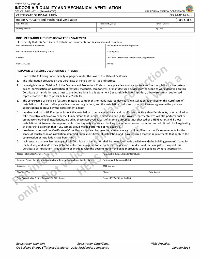
STATE OF CALIFORNIA
INDOOR AIR QUALITY AND MECHANICAL VENTILATION CEC-CF2R-MCH-27c-H (Revised 06/13) CALIFORNIA ENERGY COMMISSION
CERTIFICATE OF INSTALLATION CF2R‐MCH‐27c‐H Indoor Air Quality and Mechanical Ventilation (Page 5 of 5) Project Name: Enforcement Agency: Permit Number:
Dwelling Address: City Zip Code
Registration Number: Registration Date/Time: HERS Provider: CA Building Energy Efficiency Standards ‐ 2013 Residential Compliance January 2014
DOCUMENTATION AUTHOR'S DECLARATION STATEMENT1. I certify that this Certificate of Installation documentation is accurate and complete.
Documentation Author Name: Documentation Author Signature:
Documentation Author Company Name: Date Signed:
Address: CEA/HERS Certification Identification (If applicable):
City/State/Zip: Phone:
RESPONSIBLE PERSON'S DECLARATION STATEMENT
I certify the following under penalty of perjury, under the laws of the State of California:
1. The information provided on this Certificate of Installation is true and correct.
2. I am eligible under Division 3 of the Business and Professions Code in the applicable classification to accept responsibility for the system design, construction, or installation of features, materials, components, or manufactured devices for the scope of work identified on this Certificate of Installation and attest to the declarations in this statement (responsible builder/installer), otherwise I am an authorized representative of the responsible builder/installer.
3. The constructed or installed features, materials, components or manufactured devices (the installation) identified on this Certificate of Installation conforms to all applicable codes and regulations, and the installation conforms to the requirements given on the plans and specifications approved by the enforcement agency.
4. I understand that a HERS rater will check the installation to verify compliance, and that if such checking identifies defects; I am required to take corrective action at my expense. I understand that Energy Commission and HERS Provider representatives will also perform quality assurance checking of installations, including those approved as part of a sample group but not checked by a HERS rater, and if those installations fail to meet the requirements of such quality assurance checking, the required corrective action and additional checking/testing of other installations in that HERS sample group will be performed at my expense.
5. I reviewed a copy of the Certificate of Compliance approved by the enforcement agency that identifies the specific requirements for the scope of construction or installation identified on this Certificate of Installation, and I have ensured that the requirements that apply to the construction or installation have been met.
6. I will ensure that a registered copy of this Certificate of Installation shall be posted, or made available with the building permit(s) issued for the building, and made available to the enforcement agency for all applicable inspections. I understand that a registered copy of this Certificate of Installation is required to be included with the documentation the builder provides to the building owner at occupancy.
Responsible Builder/Installer Name: Responsible Builder/Installer Signature:
Company Name: (Installing Subcontractor or General Contractor or Builder/Owner) Position With Company (Title):
Address: CSLB License:
City/State/Zip: Phone Date Signed:
Third Party Quality Control Program (TPQCP) Status: Name of TPQCP (if applicable):
CERTIFICATE OF INSTALLATION ‐ USER INSTRUCTIONS CF2R‐MCH‐27c‐H Indoor Air Quality and Mechanical Ventilation – MCH‐27c (Page 1 of 1)
CA Building Energy Efficiency Standards ‐ 2013 Residential Compliance January 2014
User Instructions – MCH‐27c: Section A. General Information 1 This information is automatically pulled from the CF1R Choices are “single family” and “low‐rise multifamily” 2 This information is automatically pulled from the CF1R. Value to be entered in the field equals the conditioned floor area of the space, in
square feet. 3 This information is automatically pulled from the CF1R. Value to be entered in the field equals the number of bedrooms in the home. 4 Select the Ventilation Operation Schedule method used from the choices provided:
• Continuous • Intermittent
5 Select the Whole Building Ventilation Rate Calculation Method from the choices provided: • Fan Ventilation Rate Method • Total Ventilation Rate Method
6 Select the Whole Building Ventilation System Type from the choices provided: • Standalone ‐ Exhaust • Standalone ‐ Supply • Standalone ‐ Balanced
Section B. Whole Building Continuous Ventilation – Fan Ventilation Rate Method 1 This value is automatically calculated using equation 4.1a. The equation used to calculate this value in the field equals:
a. If A01= Single Family then [(0.01 x conditioned floor area A02) + 7.5(Number of bedrooms A03 + 1)] = Continuous Whole‐Building Ventilation Rate
b. If A01= Multifamily then [(0.03 x conditioned floor area A02) + 7.5(Number of bedrooms A03 + 1)] = Continuous Whole‐Building Ventilation Rate
Section C. Intermittent Ventilation 1 Intermittent ventilation requires controls that ensure a regular operating schedule every 24 hours. Within a 24 hour period there will be one
or more regular on off cycles. For a single on off cycle, enter the on time in hours. This value will be verified by a HERS rater. 2 Intermittent ventilation requires controls that ensure a regular operating schedule every 24 hours. Within a 24 hour period there will be one
or more regular on off cycles. For a single on off cycle, enter the off time in hours. This value will be verified by a HERS rater. 3 This row performs an automatic check. The intermittent ventilation system must operate at least once every 24 hours. For this to occur, the
on time plus the off time in a single on off cycle must be less than 24 hours. If this is true, “OK” will appear. If this is not true, an error will appear here and correct values will need to be entered into Rows C01 and C02. The equation used to calculate this value in the field equals: Time on in hours row C01 + Time off in hours row C02.
4 This value is automatically calculated. It is the daily fractional on time (f) used in 62.2 Table 4.2. A value of 0.60 means that in a 24 hour period the fan will run 60% of the time. The equation used to calculate this value in the field equals: On time in Hours row C01/( On time in Hours row C01 + Off time in Hours row C02)= Daily fractional on time
5 This row performs an automatic check. The ventilation system must operate at least 10% of the time. Row C04 must be greater than or equal to 0.10. If this is true, “OK” will appear. If this is not true, an error message will appear here and correct values will need to be entered into Rows C01 and C02.
6 This value is automatically calculated. It is the turnover (N) used in 62.2 Table 4.2. The equation used to calculate this value in the field equals: [12.8 x Continuous Whole‐Building Ventilation Rate row B01 x (On time in Hours row C01 + Off time in Hours row C02)]/ Conditioned floor area of dwelling unit row A02= Turnover N
7 User entered value use the daily fractional time (f) from Row C04 and the turnover (N) from Row C06 to determine the ventilation effectiveness value (e) from 62.2 table 4.2.
8 This value is automatically calculated using 62.2 equation 4.8. It represents the required airflow in cfm that must be delivered during the ventilation system on times. This value will be verified by a HERS rater. The equation used to calculate this value in the field equals: Continuous Whole‐Building Ventilation Rate row B01/( Daily fractional on time row C04 x ventilation effectiveness value row C07= required Intermittent ventilation rate
9 User entered value equals the installed intermittent ventilation rate in (CFM) 10 This information is automatically pulled from the registered MCH‐22 row B07 Note: this line only visible if CFI System selected in A06 11 This information is automatically calculated based on C10 Note: this line only visible if CFI System selected in A06
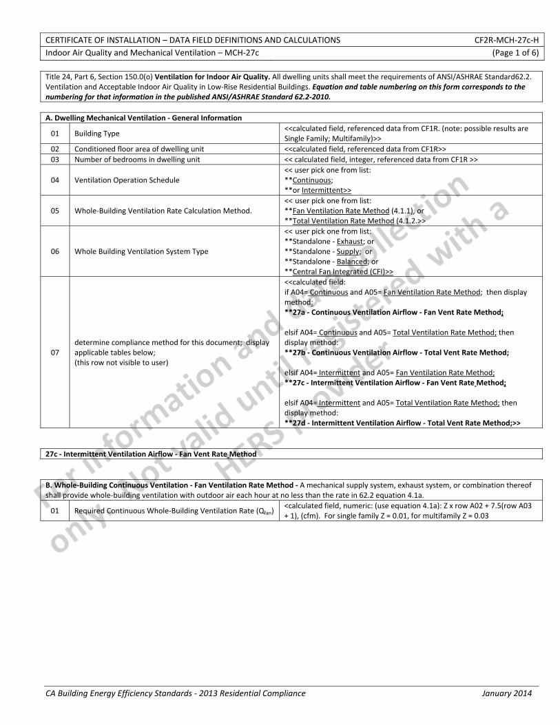
CERTIFICATE OF INSTALLATION – DATA FIELD DEFINITIONS AND CALCULATIONS CF2R‐MCH‐27c‐H Indoor Air Quality and Mechanical Ventilation – MCH‐27c (Page 1 of 6)
CA Building Energy Efficiency Standards ‐ 2013 Residential Compliance January 2014
Title 24, Part 6, Section 150.0(o) Ventilation for Indoor Air Quality. All dwelling units shall meet the requirements of ANSI/ASHRAE Standard62.2. Ventilation and Acceptable Indoor Air Quality in Low‐Rise Residential Buildings. Equation and table numbering on this form corresponds to the numbering for that information in the published ANSI/ASHRAE Standard 62.2‐2010. A. Dwelling Mechanical Ventilation ‐ General Information
01 Building Type <<calculated field, referenced data from CF1R. (note: possible results are Single Family; Multifamily)>>
02 Conditioned floor area of dwelling unit <<calculated field, referenced data from CF1R>> 03 Number of bedrooms in dwelling unit << calculated field, integer, referenced data from CF1R >>
04 Ventilation Operation Schedule << user pick one from list: **Continuous; **or Intermittent>>
05 Whole‐Building Ventilation Rate Calculation Method. << user pick one from list: **Fan Ventilation Rate Method (4.1.1), or **Total Ventilation Rate Method (4.1.2.>>
06 Whole Building Ventilation System Type
<< user pick one from list: **Standalone ‐ Exhaust; or **Standalone ‐ Supply; or **Standalone ‐ Balanced; or **Central Fan Integrated (CFI)>>
07 determine compliance method for this document; display applicable tables below; (this row not visible to user)
<<calculated field: if A04= Continuous and A05= Fan Ventilation Rate Method; then display method: **27a ‐ Continuous Ventilation Airflow ‐ Fan Vent Rate Method; elsif A04= Continuous and A05= Total Ventilation Rate Method; then display method: **27b ‐ Continuous Ventilation Airflow ‐ Total Vent Rate Method; elsif A04= Intermittent and A05= Fan Ventilation Rate Method; **27c ‐ Intermittent Ventilation Airflow ‐ Fan Vent Rate Method; elsif A04= Intermittent and A05= Total Ventilation Rate Method; then display method: **27d ‐ Intermittent Ventilation Airflow ‐ Total Vent Rate Method;>>
27c ‐ Intermittent Ventilation Airflow ‐ Fan Vent Rate Method B. Whole‐Building Continuous Ventilation ‐ Fan Ventilation Rate Method ‐ A mechanical supply system, exhaust system, or combination thereof shall provide whole‐building ventilation with outdoor air each hour at no less than the rate in 62.2 equation 4.1a.
01 Required Continuous Whole‐Building Ventilation Rate (Qfan) <calculated field, numeric: (use equation 4.1a): Z x row A02 + 7.5(row A03 + 1), (cfm). For single family Z = 0.01, for multifamily Z = 0.03
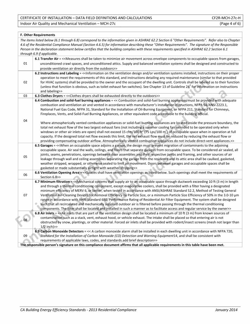
CERTIFICATE OF INSTALLATION – DATA FIELD DEFINITIONS AND CALCULATIONS CF2R‐MCH‐27c‐H Indoor Air Quality and Mechanical Ventilation – MCH‐27c (Page 4 of 6)
CA Building Energy Efficiency Standards ‐ 2013 Residential Compliance January 2014
F. Other Requirements
The items listed below (6.1 through 6.8) correspond to the information given in ASHRAE 62.2 Section 6 "Other Requirements". Refer also to Chapter 4.6 of the Residential Compliance Manual (Section 4.6.5) for information describing these "Other Requirements". The signature of the Responsible Person in the declaration statement below certifies that the building complies with these requirements specified in ASHRAE 62.2 Section 6.1 through 6.9 if applicable.
01 6.1 Transfer Air = <<Measures shall be taken to minimize air movement across envelope components to occupiable spaces from garages,
unconditioned crawl spaces, and unconditioned attics. Supply and balanced ventilation systems shall be designed and constructed to provide ventilation air directly from the outdoors>>
02
6.2 Instructions and Labeling = <<Information on the ventilation design and/or ventilation systems installed, instructions on their proper operation to meet the requirements of this standard, and instructions detailing any required maintenance (similar to that provided for HVAC systems) shall be provided to the owner and the occupant of the dwelling unit. Controls shall be labeled as to their function (unless that function is obvious, such as toilet exhaust fan switches). See Chapter 13 of Guideline 242 for information on instructions and labeling>>
03 6.3 Clothes Dryers = <<Clothes dryers shall be exhausted directly to the outdoors>>
04
6.4 Combustion and solid‐fuel burning appliances = << Combustion and solid‐fuel burning appliances must be provided with adequate combustion and ventilation air and vented in accordance with manufacturer’s installation instructions, NFPA 54/ANSI Z223.1, National Fuel Gas Code, NFPA 31, Standard for the Installation of Oil‐Burning Equipment, or NFPA 211, Standard for Chimneys, Fireplaces, Vents, and Solid‐Fuel Burning Appliances, or other equivalent code acceptable to the building official.
Where atmospherically vented combustion appliances or solid‐fuel burning appliances are located inside the pressure boundary, the total net exhaust flow of the two largest exhaust fans (not including a summer cooling fan intended to be operated only when windows or other air inlets are open) shall not exceed 15 cfm/100 ft² (75 Lps/100 m2) of occupiable space when in operation at full capacity. If the designed total net flow exceeds this limit, the net exhaust flow must be reduced by reducing the exhaust flow or providing compensating outdoor airflow. Atmospherically vented combustion appliances do not include direct‐vent appliances.>>
05
6.5 Garages = <<When an occupiable space adjoins a garage, the design must prevent migration of contaminants to the adjoining occupiable space. Air seal the walls, ceilings, and floors that separate garages from occupiable space. To be considered air sealed, all joints, seams, penetrations, openings between door assemblies and their respective jambs and framing, and other sources of air leakage through wall and ceiling assemblies separating the garage from the residence and its attic area shall be caulked, gasketed, weather stripped, wrapped, or otherwise sealed to limit air movement. Doors between garages and occupiable spaces shall be gasketed or made substantially airtight with weather stripping>>
06 6.6 Ventilation Opening Area = <<Spaces shall have ventilation openings as listed below. Such openings shall meet the requirements of
Section 6.8>>
07
6.7 Minimum filtration = <<Mechanical systems that supply air to an occupiable space through ductwork exceeding 10 ft (3 m) in length and through a thermal conditioning component, except evaporative coolers, shall be provided with a filter having a designated minimum efficiency of MERV 6, or better, when tested in accordance with ANSI/ASHRAE Standard 52.2, Method of Testing General Ventilation Air‐Cleaning Devices for Removal Efficiency by Particle Size, or a minimum Particle Size Efficiency of 50% in the 3.0‐10 µm range in accordance with AHRI Standard 680, Performance Rating of Residential Air Filter Equipment. The system shall be designed such that all recirculated and mechanically supplied outdoor air is filtered before passing through the thermal conditioning components. The filter shall be located and installed in such a manner as to facilitate access and regular service by the owner>>
08
6.8 Air Inlets = <<Air inlets that are part of the ventilation design shall be located a minimum of 10 ft (3 m) from known sources of contamination such as a stack, vent, exhaust hood, or vehicle exhaust. The intake shall be placed so that entering air is not obstructed by snow, plantings, or other material. Forced air inlets shall be provided with rodent/insect screens (mesh not larger than 1/2 inch)>>
09 6.9 Carbon Monoxide Detectors = << A carbon monoxide alarm shall be installed in each dwelling unit in accordance with NFPA 720,
Standard for the Installation of Carbon Monoxide (CO) Detection and Warning Equipment14, and shall be consistent with requirements of applicable laws, codes, and standards.add brief description>>
The responsible person’s signature on this compliance document affirms that all applicable requirements in this table have been met.

CERTIFICATE OF INSTALLATION – DATA FIELD DEFINITIONS AND CALCULATIONS CF2R‐MCH‐27c‐H Indoor Air Quality and Mechanical Ventilation – MCH‐27c (Page 5 of 6)
CA Building Energy Efficiency Standards ‐ 2013 Residential Compliance January 2014
G. Air Moving Equipment
The items listed below (7.1 through 7.3) correspond to the information given in ASHRAE 62.2 Section 7 "Air‐Moving Equipment". Refer also to Chapter 4.6 of the Residential Compliance Manual (Section 4.6.6) for information describing these requirements in more detail. The signature of the Responsible Person in the declaration statement below certifies that the building complies with these requirements specified in ASHRAE 62.2 Section 7.1 through 7.3 if applicable.
01 7.1 Selection and Installation. Ventilation devices and equipment shall be tested and listed in accordance with specific standards.
Installations of systems or equipment shall be carried out in accordance with manufacturers’ design requirements and installation instructions.
02
7.2 Sound Ratings for Fans. Ventilation fans shall be rated for sound at no less than the minimum airflow rate required by this standard, as noted below. These sound ratings shall be at a minimum of 0.1 in. w.c. (25 Pa) static pressure.
7.2.1 Whole‐Building or Continuous Ventilation Fans. These fans shall be rated for sound at a maximum of 1.0 sone. 7.2.2 Intermittent Local Exhaust Fans. Fans used to comply with Section 5.2 shall be rated for sound at a maximum of 3 sone,
unless their maximum rated airflow exceeds 400 cfm (200 L/s). (Some exceptions may apply.)
03 7.3 Multibranch Exhaust Ducting. If more than one of the exhaust fans in a dwelling unit shares a common exhaust duct, each fan shall be equipped with a back‐draft damper to prevent the recirculation of exhaust air from one room to another through the exhaust ducting system.
The responsible person’s signature on this compliance document affirms that all applicable requirements in this table have been met.
H. Multifamily Buildings ‐ Other Requirements <<only print this section if multi‐family is selected in row A.1>>
The items listed below correspond to the information given in ASHRAE 62.2 Section 8 "Multifamily Buildings". Refer also to Chapter 4.6 of the Residential Compliance Manual (Section 4.6.5) for information describing these requirements in more detail. The signature of the Responsible Person in the declaration statement below certifies that the building complies with these requirements specified in ASHRAE 62.2 Section 8, if applicable.
01
8.4.1 Transfer Air. Measures shall be taken to minimize air movement across envelope components separating dwelling units, including sealing penetrations in the common walls, ceilings, and floors of each unit and by sealing vertical chases adjacent to the units. All doors between dwelling units and common hallways shall be gasketed or made substantially airtight.
8.4.1.1 Compliance. One method of demonstrating compliance with Section 8.4.1 shall be to verify a leakage rate below a maximum of 0.2 cfm per ft2 (100 L/s per 100 m2) of the dwelling unit envelope area (i.e., the sum of the area of the walls between dwelling units, exterior walls, ceiling and floor) at a test pressure of 50 Pa by a blower door test. The test shall be conducted with the dwelling unit as if it were exposed to outdoor air on all sides, top, and bottom by opening doors and windows of adjacent dwelling units.
The responsible person’s signature on this compliance document affirms that all applicable requirements in this table have been met.

CERTIFICATE OF INSTALLATION – DATA FIELD DEFINITIONS AND CALCULATIONS CF2R‐MCH‐27c‐H Indoor Air Quality and Mechanical Ventilation – MCH‐27c (Page 6 of 6)
CA Building Energy Efficiency Standards ‐ 2013 Residential Compliance January 2014
DOCUMENTATION AUTHOR'S DECLARATION STATEMENT1. I certify that this Certificate of Installation documentation is accurate and complete.
Documentation Author Name: Documentation Author Signature:
Documentation Author Company Name: Date Signed:
Address: CEA/HERS Certification Identification (If applicable):
City/State/Zip: Phone:
RESPONSIBLE PERSON'S DECLARATION STATEMENT
I certify the following under penalty of perjury, under the laws of the State of California:
1. The information provided on this Certificate of Installation is true and correct.
2. I am eligible under Division 3 of the Business and Professions Code in the applicable classification to accept responsibility for the system design, construction, or installation of features, materials, components, or manufactured devices for the scope of work identified on this Certificate of Installation and attest to the declarations in this statement (responsible builder/installer), otherwise I am an authorized representative of the responsible builder/installer.
3. The constructed or installed features, materials, components or manufactured devices (the installation) identified on this Certificate of Installation conforms to all applicable codes and regulations, and the installation conforms to the requirements given on the plans and specifications approved by the enforcement agency.
4. I understand that a HERS rater will check the installation to verify compliance, and that if such checking identifies defects; I am required to take corrective action at my expense. I understand that Energy Commission and HERS Provider representatives will also perform quality assurance checking of installations, including those approved as part of a sample group but not checked by a HERS rater, and if those installations fail to meet the requirements of such quality assurance checking, the required corrective action and additional checking/testing of other installations in that HERS sample group will be performed at my expense.
5. I reviewed a copy of the Certificate of Compliance approved by the enforcement agency that identifies the specific requirements for the scope of construction or installation identified on this Certificate of Installation, and I have ensured that the requirements that apply to the construction or installation have been met.
6. I will ensure that a registered copy of this Certificate of Installation shall be posted, or made available with the building permit(s) issued for the building, and made available to the enforcement agency for all applicable inspections. I understand that a registered copy of this Certificate of Installation is required to be included with the documentation the builder provides to the building owner at occupancy.
Responsible Builder/Installer Name: Responsible Builder/Installer Signature:
Company Name: (Installing Subcontractor or General Contractor or Builder/Owner) Position With Company (Title):
Address: CSLB License:
City/State/Zip: Phone Date Signed:
Third Party Quality Control Program (TPQCP) Status: Name of TPQCP (if applicable):
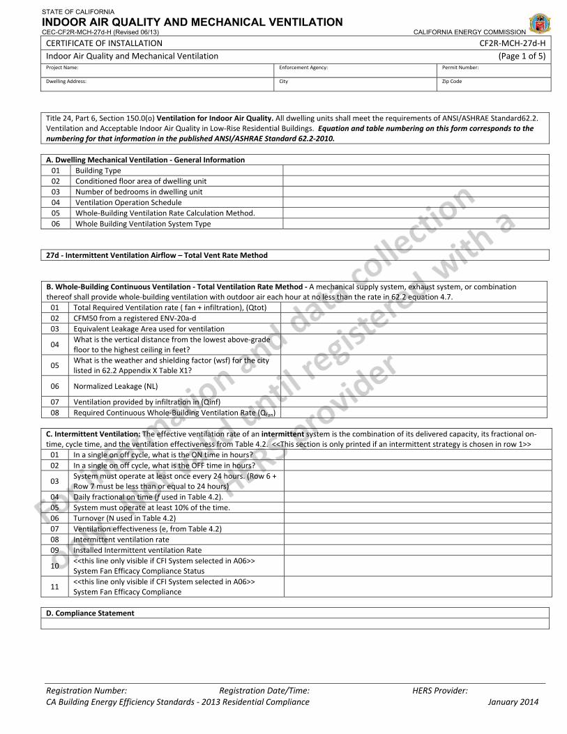
STATE OF CALIFORNIA
INDOOR AIR QUALITY AND MECHANICAL VENTILATION CEC-CF2R-MCH-27d-H (Revised 06/13) CALIFORNIA ENERGY COMMISSION
CERTIFICATE OF INSTALLATION CF2R‐MCH‐27d‐H Indoor Air Quality and Mechanical Ventilation (Page 1 of 5) Project Name: Enforcement Agency: Permit Number:
Dwelling Address: City Zip Code
Registration Number: Registration Date/Time: HERS Provider: CA Building Energy Efficiency Standards ‐ 2013 Residential Compliance January 2014
Title 24, Part 6, Section 150.0(o) Ventilation for Indoor Air Quality. All dwelling units shall meet the requirements of ANSI/ASHRAE Standard62.2. Ventilation and Acceptable Indoor Air Quality in Low‐Rise Residential Buildings. Equation and table numbering on this form corresponds to the numbering for that information in the published ANSI/ASHRAE Standard 62.2‐2010. A. Dwelling Mechanical Ventilation ‐ General Information 01 Building Type 02 Conditioned floor area of dwelling unit 03 Number of bedrooms in dwelling unit 04 Ventilation Operation Schedule 05 Whole‐Building Ventilation Rate Calculation Method. 06 Whole Building Ventilation System Type
27d ‐ Intermittent Ventilation Airflow – Total Vent Rate Method B. Whole‐Building Continuous Ventilation ‐ Total Ventilation Rate Method ‐ A mechanical supply system, exhaust system, or combination thereof shall provide whole‐building ventilation with outdoor air each hour at no less than the rate in 62.2 equation 4.7. 01 Total Required Ventilation rate ( fan + infiltration), (Qtot) 02 CFM50 from a registered ENV‐20a‐d 03 Equivalent Leakage Area used for ventilation
04 What is the vertical distance from the lowest above‐grade floor to the highest ceiling in feet?
05 What is the weather and shielding factor (wsf) for the city listed in 62.2 Appendix X Table X1?
06 Normalized Leakage (NL)
07 Ventilation provided by infiltration in (Qinf) 08 Required Continuous Whole‐Building Ventilation Rate (Qfan)
C. Intermittent Ventilation: The effective ventilation rate of an intermittent system is the combination of its delivered capacity, its fractional on‐time, cycle time, and the ventilation effectiveness from Table 4.2. <<This section is only printed if an intermittent strategy is chosen in row 1>> 01 In a single on off cycle, what is the ON time in hours? 02 In a single on off cycle, what is the OFF time in hours?
03 System must operate at least once every 24 hours. (Row 6 + Row 7 must be less than or equal to 24 hours)
04 Daily fractional on time (f used in Table 4.2). 05 System must operate at least 10% of the time. 06 Turnover (N used in Table 4.2) 07 Ventilation effectiveness (e, from Table 4.2) 08 Intermittent ventilation rate 09 Installed Intermittent ventilation Rate
10 <<this line only visible if CFI System selected in A06>> System Fan Efficacy Compliance Status
11 <<this line only visible if CFI System selected in A06>> System Fan Efficacy Compliance
D. Compliance Statement
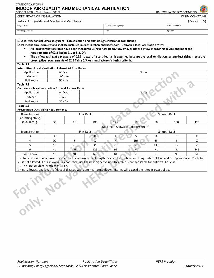
STATE OF CALIFORNIA
INDOOR AIR QUALITY AND MECHANICAL VENTILATION CEC-CF2R-MCH-27d-H (Revised 06/13) CALIFORNIA ENERGY COMMISSION
CERTIFICATE OF INSTALLATION CF2R‐MCH‐27d‐H Indoor Air Quality and Mechanical Ventilation (Page 2 of 5) Project Name: Enforcement Agency: Permit Number:
Dwelling Address: City Zip Code
Registration Number: Registration Date/Time: HERS Provider: CA Building Energy Efficiency Standards ‐ 2013 Residential Compliance January 2014
E. Local Mechanical Exhaust System – Fan selection and duct design criteria for compliance Local mechanical exhaust fans shall be installed in each kitchen and bathroom. Delivered local ventilation rates:
All local ventilation rates have been measured using a flow hood, flow grid, or other airflow measuring device and meet the requirements of 62.2 Tables 5.1 or 5.2. OR
The airflow rating at a pressure of 0.25 in. w.c. of a certified fan is assumed because the local ventilation system duct sizing meets the prescriptive requirements of 62.2 Table 5.3, or manufacturer's design criteria.
Table 5.1 Intermittent Local Ventilation Exhaust Airflow Rates
Application Airflow Notes Kitchen 100 cfm
Bathroom 50 cfm Table 5.2 Continuous Local Ventilation Exhaust Airflow Rates
Application Airflow Notes Kitchen 5 ACH
Bathroom 20 cfm Table 5.3 Prescriptive Duct Sizing Requirements
Diameter, (in) Flex Duct Smooth Duct Fan Rating cfm @
0.25 in. w.g. 50 80 100 125 50 80 100 125 Maximum Allowable Duct Length (ft)
Diameter, (in) Flex Duct Smooth Duct 3 X X X X 5 X X X 4 70 3 X X 105 35 5 X 5 NL 70 35 20 NL 135 85 55 6 NL NL 125 95 NL NL NL 145
7 and above NL NL NL NL NL NL NL NL This table assumes no elbows. Deduct 15 ft of allowable duct length for each turn, elbow, or fitting. Interpolation and extrapolation in 62.2 Table 5.3 is not allowed. For airflow values not listed, use the next higher value. This table is not applicable for airflow > 125 cfm. NL = no limit on duct length of this size. X = not allowed, any length of duct of this size with assumed turns, elbows, fittings will exceed the rated pressure drop.
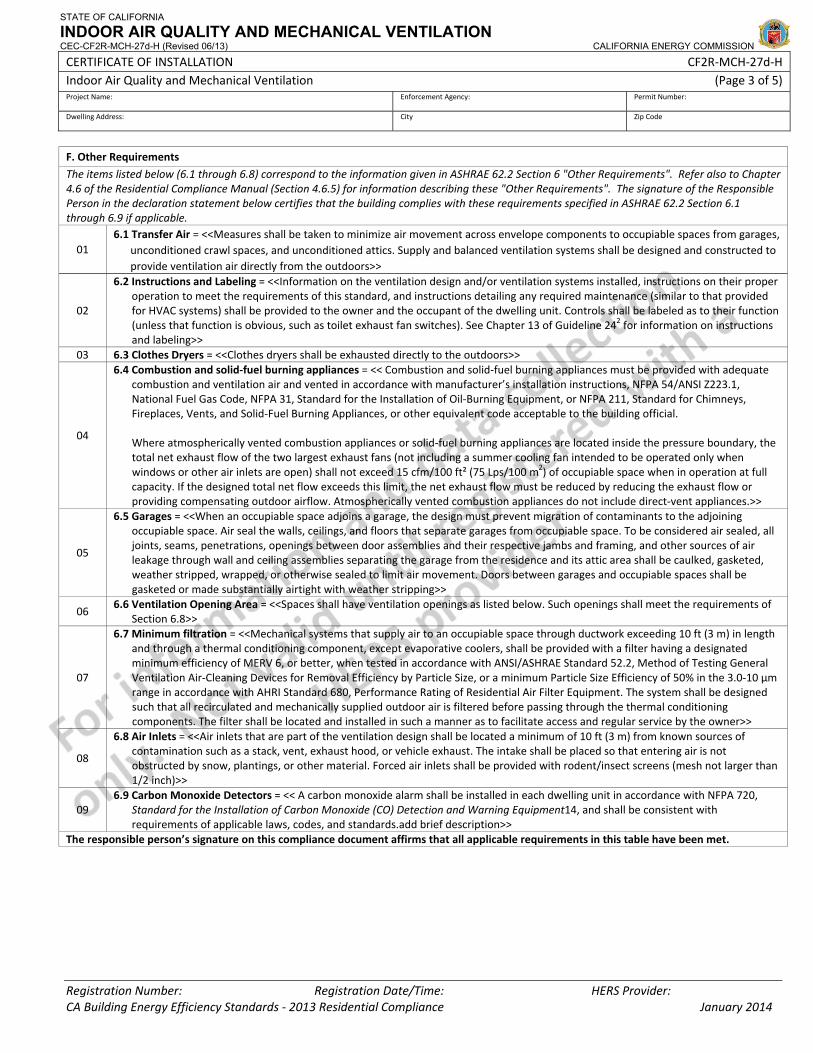
STATE OF CALIFORNIA
INDOOR AIR QUALITY AND MECHANICAL VENTILATION CEC-CF2R-MCH-27d-H (Revised 06/13) CALIFORNIA ENERGY COMMISSION
CERTIFICATE OF INSTALLATION CF2R‐MCH‐27d‐H Indoor Air Quality and Mechanical Ventilation (Page 3 of 5) Project Name: Enforcement Agency: Permit Number:
Dwelling Address: City Zip Code
Registration Number: Registration Date/Time: HERS Provider: CA Building Energy Efficiency Standards ‐ 2013 Residential Compliance January 2014
F. Other Requirements
The items listed below (6.1 through 6.8) correspond to the information given in ASHRAE 62.2 Section 6 "Other Requirements". Refer also to Chapter 4.6 of the Residential Compliance Manual (Section 4.6.5) for information describing these "Other Requirements". The signature of the Responsible Person in the declaration statement below certifies that the building complies with these requirements specified in ASHRAE 62.2 Section 6.1 through 6.9 if applicable.
01 6.1 Transfer Air = <<Measures shall be taken to minimize air movement across envelope components to occupiable spaces from garages,
unconditioned crawl spaces, and unconditioned attics. Supply and balanced ventilation systems shall be designed and constructed to provide ventilation air directly from the outdoors>>
02
6.2 Instructions and Labeling = <<Information on the ventilation design and/or ventilation systems installed, instructions on their proper operation to meet the requirements of this standard, and instructions detailing any required maintenance (similar to that provided for HVAC systems) shall be provided to the owner and the occupant of the dwelling unit. Controls shall be labeled as to their function (unless that function is obvious, such as toilet exhaust fan switches). See Chapter 13 of Guideline 242 for information on instructions and labeling>>
03 6.3 Clothes Dryers = <<Clothes dryers shall be exhausted directly to the outdoors>>
04
6.4 Combustion and solid‐fuel burning appliances = << Combustion and solid‐fuel burning appliances must be provided with adequate combustion and ventilation air and vented in accordance with manufacturer’s installation instructions, NFPA 54/ANSI Z223.1, National Fuel Gas Code, NFPA 31, Standard for the Installation of Oil‐Burning Equipment, or NFPA 211, Standard for Chimneys, Fireplaces, Vents, and Solid‐Fuel Burning Appliances, or other equivalent code acceptable to the building official.
Where atmospherically vented combustion appliances or solid‐fuel burning appliances are located inside the pressure boundary, the total net exhaust flow of the two largest exhaust fans (not including a summer cooling fan intended to be operated only when windows or other air inlets are open) shall not exceed 15 cfm/100 ft² (75 Lps/100 m2) of occupiable space when in operation at full capacity. If the designed total net flow exceeds this limit, the net exhaust flow must be reduced by reducing the exhaust flow or providing compensating outdoor airflow. Atmospherically vented combustion appliances do not include direct‐vent appliances.>>
05
6.5 Garages = <<When an occupiable space adjoins a garage, the design must prevent migration of contaminants to the adjoining occupiable space. Air seal the walls, ceilings, and floors that separate garages from occupiable space. To be considered air sealed, all joints, seams, penetrations, openings between door assemblies and their respective jambs and framing, and other sources of air leakage through wall and ceiling assemblies separating the garage from the residence and its attic area shall be caulked, gasketed, weather stripped, wrapped, or otherwise sealed to limit air movement. Doors between garages and occupiable spaces shall be gasketed or made substantially airtight with weather stripping>>
06 6.6 Ventilation Opening Area = <<Spaces shall have ventilation openings as listed below. Such openings shall meet the requirements of
Section 6.8>>
07
6.7 Minimum filtration = <<Mechanical systems that supply air to an occupiable space through ductwork exceeding 10 ft (3 m) in length and through a thermal conditioning component, except evaporative coolers, shall be provided with a filter having a designated minimum efficiency of MERV 6, or better, when tested in accordance with ANSI/ASHRAE Standard 52.2, Method of Testing General Ventilation Air‐Cleaning Devices for Removal Efficiency by Particle Size, or a minimum Particle Size Efficiency of 50% in the 3.0‐10 µm range in accordance with AHRI Standard 680, Performance Rating of Residential Air Filter Equipment. The system shall be designed such that all recirculated and mechanically supplied outdoor air is filtered before passing through the thermal conditioning components. The filter shall be located and installed in such a manner as to facilitate access and regular service by the owner>>
08
6.8 Air Inlets = <<Air inlets that are part of the ventilation design shall be located a minimum of 10 ft (3 m) from known sources of contamination such as a stack, vent, exhaust hood, or vehicle exhaust. The intake shall be placed so that entering air is not obstructed by snow, plantings, or other material. Forced air inlets shall be provided with rodent/insect screens (mesh not larger than 1/2 inch)>>
09 6.9 Carbon Monoxide Detectors = << A carbon monoxide alarm shall be installed in each dwelling unit in accordance with NFPA 720,
Standard for the Installation of Carbon Monoxide (CO) Detection and Warning Equipment14, and shall be consistent with requirements of applicable laws, codes, and standards.add brief description>>
The responsible person’s signature on this compliance document affirms that all applicable requirements in this table have been met.
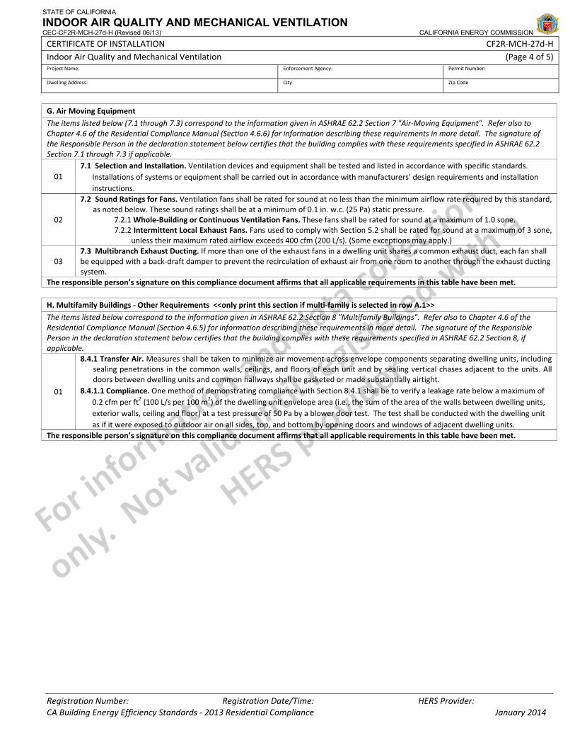
STATE OF CALIFORNIA
INDOOR AIR QUALITY AND MECHANICAL VENTILATION CEC-CF2R-MCH-27d-H (Revised 06/13) CALIFORNIA ENERGY COMMISSION
CERTIFICATE OF INSTALLATION CF2R‐MCH‐27d‐H Indoor Air Quality and Mechanical Ventilation (Page 4 of 5) Project Name: Enforcement Agency: Permit Number:
Dwelling Address: City Zip Code
Registration Number: Registration Date/Time: HERS Provider: CA Building Energy Efficiency Standards ‐ 2013 Residential Compliance January 2014
G. Air Moving Equipment
The items listed below (7.1 through 7.3) correspond to the information given in ASHRAE 62.2 Section 7 "Air‐Moving Equipment". Refer also to Chapter 4.6 of the Residential Compliance Manual (Section 4.6.6) for information describing these requirements in more detail. The signature of the Responsible Person in the declaration statement below certifies that the building complies with these requirements specified in ASHRAE 62.2 Section 7.1 through 7.3 if applicable.
01 7.1 Selection and Installation. Ventilation devices and equipment shall be tested and listed in accordance with specific standards.
Installations of systems or equipment shall be carried out in accordance with manufacturers’ design requirements and installation instructions.
02
7.2 Sound Ratings for Fans. Ventilation fans shall be rated for sound at no less than the minimum airflow rate required by this standard, as noted below. These sound ratings shall be at a minimum of 0.1 in. w.c. (25 Pa) static pressure.
7.2.1 Whole‐Building or Continuous Ventilation Fans. These fans shall be rated for sound at a maximum of 1.0 sone. 7.2.2 Intermittent Local Exhaust Fans. Fans used to comply with Section 5.2 shall be rated for sound at a maximum of 3 sone,
unless their maximum rated airflow exceeds 400 cfm (200 L/s). (Some exceptions may apply.)
03 7.3 Multibranch Exhaust Ducting. If more than one of the exhaust fans in a dwelling unit shares a common exhaust duct, each fan shall be equipped with a back‐draft damper to prevent the recirculation of exhaust air from one room to another through the exhaust ducting system.
The responsible person’s signature on this compliance document affirms that all applicable requirements in this table have been met.
H. Multifamily Buildings ‐ Other Requirements <<only print this section if multi‐family is selected in row A.1>>
The items listed below correspond to the information given in ASHRAE 62.2 Section 8 "Multifamily Buildings". Refer also to Chapter 4.6 of the Residential Compliance Manual (Section 4.6.5) for information describing these requirements in more detail. The signature of the Responsible Person in the declaration statement below certifies that the building complies with these requirements specified in ASHRAE 62.2 Section 8, if applicable.
01
8.4.1 Transfer Air. Measures shall be taken to minimize air movement across envelope components separating dwelling units, including sealing penetrations in the common walls, ceilings, and floors of each unit and by sealing vertical chases adjacent to the units. All doors between dwelling units and common hallways shall be gasketed or made substantially airtight.
8.4.1.1 Compliance. One method of demonstrating compliance with Section 8.4.1 shall be to verify a leakage rate below a maximum of 0.2 cfm per ft2 (100 L/s per 100 m2) of the dwelling unit envelope area (i.e., the sum of the area of the walls between dwelling units, exterior walls, ceiling and floor) at a test pressure of 50 Pa by a blower door test. The test shall be conducted with the dwelling unit as if it were exposed to outdoor air on all sides, top, and bottom by opening doors and windows of adjacent dwelling units.
The responsible person’s signature on this compliance document affirms that all applicable requirements in this table have been met.
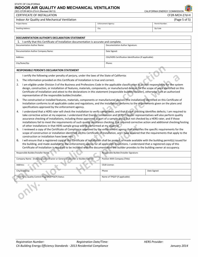
STATE OF CALIFORNIA
INDOOR AIR QUALITY AND MECHANICAL VENTILATION CEC-CF2R-MCH-27d-H (Revised 06/13) CALIFORNIA ENERGY COMMISSION
CERTIFICATE OF INSTALLATION CF2R‐MCH‐27d‐H Indoor Air Quality and Mechanical Ventilation (Page 5 of 5) Project Name: Enforcement Agency: Permit Number:
Dwelling Address: City Zip Code
Registration Number: Registration Date/Time: HERS Provider: CA Building Energy Efficiency Standards ‐ 2013 Residential Compliance January 2014
DOCUMENTATION AUTHOR'S DECLARATION STATEMENT1. I certify that this Certificate of Installation documentation is accurate and complete.
Documentation Author Name: Documentation Author Signature:
Documentation Author Company Name: Date Signed:
Address: CEA/HERS Certification Identification (If applicable):
City/State/Zip: Phone:
RESPONSIBLE PERSON'S DECLARATION STATEMENT
I certify the following under penalty of perjury, under the laws of the State of California:
1. The information provided on this Certificate of Installation is true and correct.
2. I am eligible under Division 3 of the Business and Professions Code in the applicable classification to accept responsibility for the system design, construction, or installation of features, materials, components, or manufactured devices for the scope of work identified on this Certificate of Installation and attest to the declarations in this statement (responsible builder/installer), otherwise I am an authorized representative of the responsible builder/installer.
3. The constructed or installed features, materials, components or manufactured devices (the installation) identified on this Certificate of Installation conforms to all applicable codes and regulations, and the installation conforms to the requirements given on the plans and specifications approved by the enforcement agency.
4. I understand that a HERS rater will check the installation to verify compliance, and that if such checking identifies defects; I am required to take corrective action at my expense. I understand that Energy Commission and HERS Provider representatives will also perform quality assurance checking of installations, including those approved as part of a sample group but not checked by a HERS rater, and if those installations fail to meet the requirements of such quality assurance checking, the required corrective action and additional checking/testing of other installations in that HERS sample group will be performed at my expense.
5. I reviewed a copy of the Certificate of Compliance approved by the enforcement agency that identifies the specific requirements for the scope of construction or installation identified on this Certificate of Installation, and I have ensured that the requirements that apply to the construction or installation have been met.
6. I will ensure that a registered copy of this Certificate of Installation shall be posted, or made available with the building permit(s) issued for the building, and made available to the enforcement agency for all applicable inspections. I understand that a registered copy of this Certificate of Installation is required to be included with the documentation the builder provides to the building owner at occupancy.
Responsible Builder/Installer Name: Responsible Builder/Installer Signature:
Company Name: (Installing Subcontractor or General Contractor or Builder/Owner) Position With Company (Title):
Address: CSLB License:
City/State/Zip: Phone Date Signed:
Third Party Quality Control Program (TPQCP) Status: Name of TPQCP (if applicable):
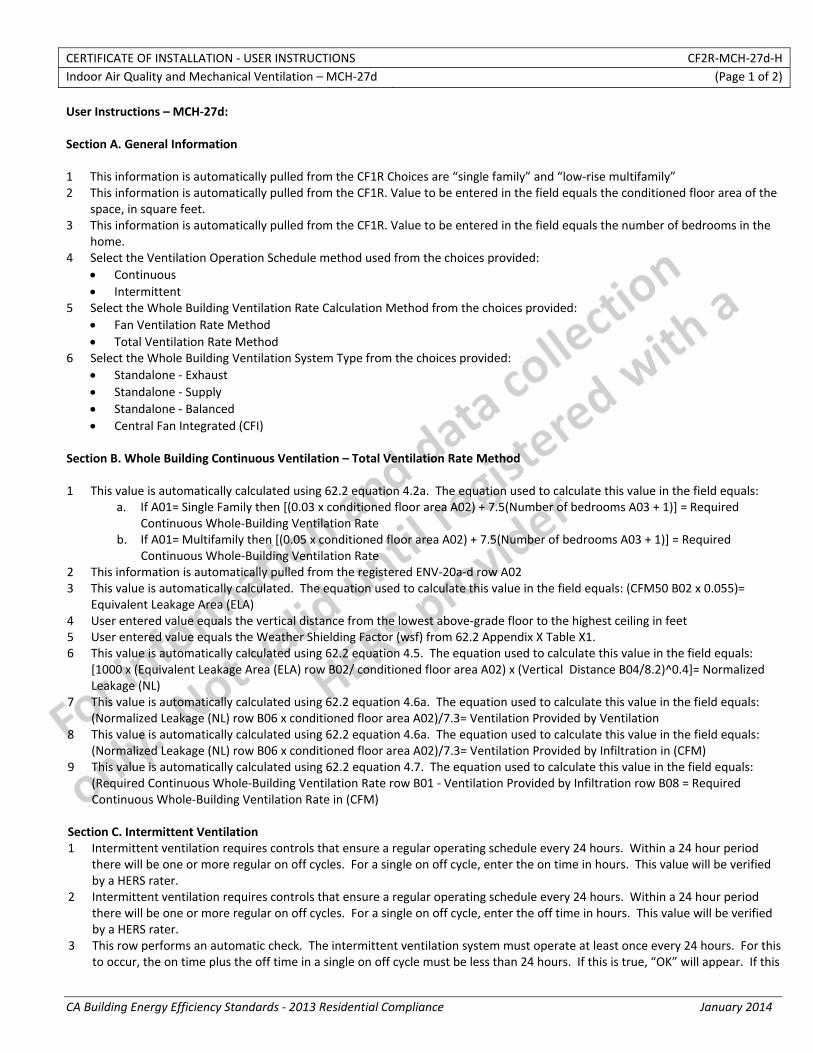
CERTIFICATE OF INSTALLATION ‐ USER INSTRUCTIONS CF2R‐MCH‐27d‐H Indoor Air Quality and Mechanical Ventilation – MCH‐27d (Page 1 of 2)
CA Building Energy Efficiency Standards ‐ 2013 Residential Compliance January 2014
User Instructions – MCH‐27d: Section A. General Information 1 This information is automatically pulled from the CF1R Choices are “single family” and “low‐rise multifamily” 2 This information is automatically pulled from the CF1R. Value to be entered in the field equals the conditioned floor area of the
space, in square feet. 3 This information is automatically pulled from the CF1R. Value to be entered in the field equals the number of bedrooms in the
home. 4 Select the Ventilation Operation Schedule method used from the choices provided:
• Continuous • Intermittent
5 Select the Whole Building Ventilation Rate Calculation Method from the choices provided: • Fan Ventilation Rate Method • Total Ventilation Rate Method
6 Select the Whole Building Ventilation System Type from the choices provided: • Standalone ‐ Exhaust • Standalone ‐ Supply • Standalone ‐ Balanced • Central Fan Integrated (CFI)
Section B. Whole Building Continuous Ventilation – Total Ventilation Rate Method 1 This value is automatically calculated using 62.2 equation 4.2a. The equation used to calculate this value in the field equals:
a. If A01= Single Family then [(0.03 x conditioned floor area A02) + 7.5(Number of bedrooms A03 + 1)] = Required Continuous Whole‐Building Ventilation Rate
b. If A01= Multifamily then [(0.05 x conditioned floor area A02) + 7.5(Number of bedrooms A03 + 1)] = Required Continuous Whole‐Building Ventilation Rate
2 This information is automatically pulled from the registered ENV‐20a‐d row A02 3 This value is automatically calculated. The equation used to calculate this value in the field equals: (CFM50 B02 x 0.055)=
Equivalent Leakage Area (ELA) 4 User entered value equals the vertical distance from the lowest above‐grade floor to the highest ceiling in feet 5 User entered value equals the Weather Shielding Factor (wsf) from 62.2 Appendix X Table X1. 6 This value is automatically calculated using 62.2 equation 4.5. The equation used to calculate this value in the field equals:
[1000 x (Equivalent Leakage Area (ELA) row B02/ conditioned floor area A02) x (Vertical Distance B04/8.2)^0.4]= Normalized Leakage (NL)
7 This value is automatically calculated using 62.2 equation 4.6a. The equation used to calculate this value in the field equals: (Normalized Leakage (NL) row B06 x conditioned floor area A02)/7.3= Ventilation Provided by Ventilation
8 This value is automatically calculated using 62.2 equation 4.6a. The equation used to calculate this value in the field equals: (Normalized Leakage (NL) row B06 x conditioned floor area A02)/7.3= Ventilation Provided by Infiltration in (CFM)
9 This value is automatically calculated using 62.2 equation 4.7. The equation used to calculate this value in the field equals: (Required Continuous Whole‐Building Ventilation Rate row B01 ‐ Ventilation Provided by Infiltration row B08 = Required Continuous Whole‐Building Ventilation Rate in (CFM)
Section C. Intermittent Ventilation 1 Intermittent ventilation requires controls that ensure a regular operating schedule every 24 hours. Within a 24 hour period
there will be one or more regular on off cycles. For a single on off cycle, enter the on time in hours. This value will be verified by a HERS rater.
2 Intermittent ventilation requires controls that ensure a regular operating schedule every 24 hours. Within a 24 hour period there will be one or more regular on off cycles. For a single on off cycle, enter the off time in hours. This value will be verified by a HERS rater.
3 This row performs an automatic check. The intermittent ventilation system must operate at least once every 24 hours. For this to occur, the on time plus the off time in a single on off cycle must be less than 24 hours. If this is true, “OK” will appear. If this
CERTIFICATE OF INSTALLATION ‐ USER INSTRUCTIONS CF2R‐MCH‐27d‐H Indoor Air Quality and Mechanical Ventilation – MCH‐27d (Page 2 of 2)
CA Building Energy Efficiency Standards ‐ 2013 Residential Compliance January 2014
is not true, an error will appear here and correct values will need to be entered into Rows C01 and C02. The equation used to calculate this value in the field equals: Time on in hours row C01 + Time off in hours row C02.
4 This value is automatically calculated. It is the daily fractional on time (f) used in 62.2 Table 4.2. A value of 0.60 means that in a 24 hour period the fan will run 60% of the time. The equation used to calculate this value in the field equals: On time in Hours row C01/( On time in Hours row C01 + Off time in Hours row C02)= Daily fractional on time
5 This row performs an automatic check. The ventilation system must operate at least 10% of the time. Row C04 must be greater than or equal to 0.10. If this is true, “OK” will appear. If this is not true, an error message will appear here and correct values will need to be entered into Rows C01 and C02.
6 This value is automatically calculated. It is the turnover (N) used in 62.2 Table 4.2. The equation used to calculate this value in the field equals: [12.8 x Continuous Whole‐Building Ventilation Rate row B01 x (On time in Hours row C01 + Off time in Hours row C02)]/ Conditioned floor area of dwelling unit row A02= Turnover N
7 User entered value use the daily fractional time (f) from Row C04 and the turnover (N) from Row C06 to determine the ventilation effectiveness value (e) from 62.2 table 4.2.
8 This value is automatically calculated using 62.2 equation 4.8. It represents the required airflow in cfm that must be delivered during the ventilation system on times. This value will be verified by a HERS rater. The equation used to calculate this value in the field equals: Continuous Whole‐Building Ventilation Rate row B01/( Daily fractional on time row C04 x ventilation effectiveness value row C07= required Intermittent ventilation rate
9 User entered value equals the installed intermittent ventilation rate in (CFM) 10 This information is automatically pulled from the registered MCH‐22 row B07 Note: this line only visible if CFI System selected
in A06 11 This information is automatically calculated based on C10 Note: this line only visible if CFI System selected in A06
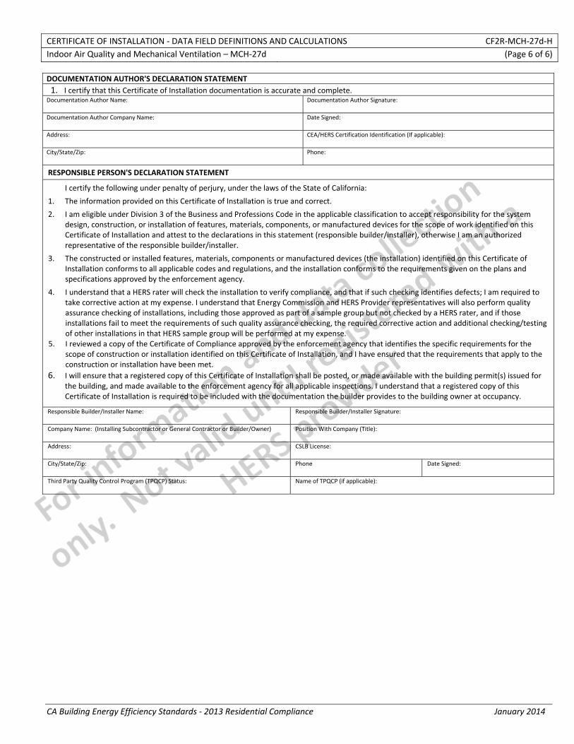
CERTIFICATE OF INSTALLATION ‐ DATA FIELD DEFINITIONS AND CALCULATIONS CF2R‐MCH‐27d‐H Indoor Air Quality and Mechanical Ventilation – MCH‐27d (Page 6 of 6)
CA Building Energy Efficiency Standards ‐ 2013 Residential Compliance January 2014
DOCUMENTATION AUTHOR'S DECLARATION STATEMENT1. I certify that this Certificate of Installation documentation is accurate and complete.
Documentation Author Name: Documentation Author Signature:
Documentation Author Company Name: Date Signed:
Address: CEA/HERS Certification Identification (If applicable):
City/State/Zip: Phone:
RESPONSIBLE PERSON'S DECLARATION STATEMENT
I certify the following under penalty of perjury, under the laws of the State of California:
1. The information provided on this Certificate of Installation is true and correct.
2. I am eligible under Division 3 of the Business and Professions Code in the applicable classification to accept responsibility for the system design, construction, or installation of features, materials, components, or manufactured devices for the scope of work identified on this Certificate of Installation and attest to the declarations in this statement (responsible builder/installer), otherwise I am an authorized representative of the responsible builder/installer.
3. The constructed or installed features, materials, components or manufactured devices (the installation) identified on this Certificate of Installation conforms to all applicable codes and regulations, and the installation conforms to the requirements given on the plans and specifications approved by the enforcement agency.
4. I understand that a HERS rater will check the installation to verify compliance, and that if such checking identifies defects; I am required to take corrective action at my expense. I understand that Energy Commission and HERS Provider representatives will also perform quality assurance checking of installations, including those approved as part of a sample group but not checked by a HERS rater, and if those installations fail to meet the requirements of such quality assurance checking, the required corrective action and additional checking/testing of other installations in that HERS sample group will be performed at my expense.
5. I reviewed a copy of the Certificate of Compliance approved by the enforcement agency that identifies the specific requirements for the scope of construction or installation identified on this Certificate of Installation, and I have ensured that the requirements that apply to the construction or installation have been met.
6. I will ensure that a registered copy of this Certificate of Installation shall be posted, or made available with the building permit(s) issued for the building, and made available to the enforcement agency for all applicable inspections. I understand that a registered copy of this Certificate of Installation is required to be included with the documentation the builder provides to the building owner at occupancy.
Responsible Builder/Installer Name: Responsible Builder/Installer Signature:
Company Name: (Installing Subcontractor or General Contractor or Builder/Owner) Position With Company (Title):
Address: CSLB License:
City/State/Zip: Phone Date Signed:
Third Party Quality Control Program (TPQCP) Status: Name of TPQCP (if applicable):
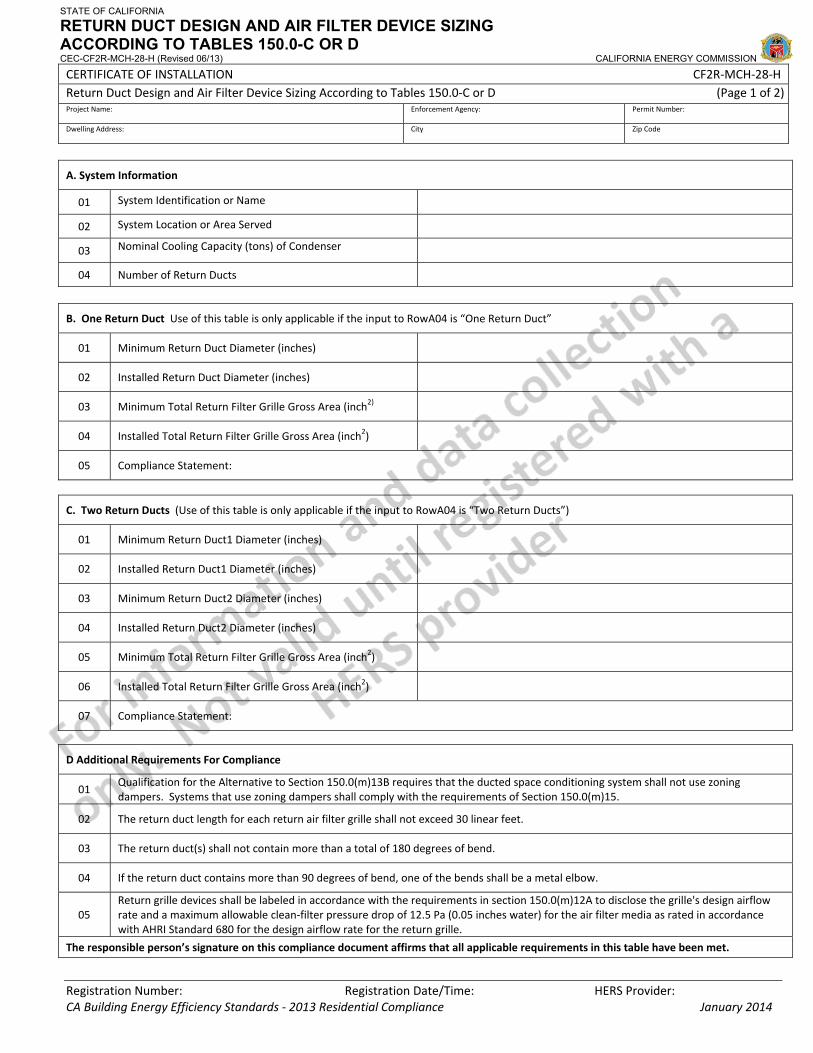
STATE OF CALIFORNIA
RETURN DUCT DESIGN AND AIR FILTER DEVICE SIZING ACCORDING TO TABLES 150.0-C OR D CEC-CF2R-MCH-28-H (Revised 06/13) CALIFORNIA ENERGY COMMISSION
CERTIFICATE OF INSTALLATION CF2R‐MCH‐28‐H Return Duct Design and Air Filter Device Sizing According to Tables 150.0‐C or D (Page 1 of 2) Project Name: Enforcement Agency: Permit Number:
Dwelling Address: City Zip Code
Registration Number: Registration Date/Time: HERS Provider: CA Building Energy Efficiency Standards ‐ 2013 Residential Compliance January 2014
A. System Information
01 System Identification or Name
02 System Location or Area Served
03 Nominal Cooling Capacity (tons) of Condenser
04 Number of Return Ducts
B. One Return Duct Use of this table is only applicable if the input to RowA04 is “One Return Duct”
01 Minimum Return Duct Diameter (inches)
02 Installed Return Duct Diameter (inches)
03 Minimum Total Return Filter Grille Gross Area (inch2)
04 Installed Total Return Filter Grille Gross Area (inch2)
05 Compliance Statement:
C. Two Return Ducts (Use of this table is only applicable if the input to RowA04 is “Two Return Ducts”)
01 Minimum Return Duct1 Diameter (inches)
02 Installed Return Duct1 Diameter (inches)
03 Minimum Return Duct2 Diameter (inches)
04 Installed Return Duct2 Diameter (inches)
05 Minimum Total Return Filter Grille Gross Area (inch2)
06 Installed Total Return Filter Grille Gross Area (inch2)
07 Compliance Statement:
D Additional Requirements For Compliance
01 Qualification for the Alternative to Section 150.0(m)13B requires that the ducted space conditioning system shall not use zoning dampers. Systems that use zoning dampers shall comply with the requirements of Section 150.0(m)15.
02 The return duct length for each return air filter grille shall not exceed 30 linear feet.
03 The return duct(s) shall not contain more than a total of 180 degrees of bend.
04 If the return duct contains more than 90 degrees of bend, one of the bends shall be a metal elbow.
05 Return grille devices shall be labeled in accordance with the requirements in section 150.0(m)12A to disclose the grille's design airflow rate and a maximum allowable clean‐filter pressure drop of 12.5 Pa (0.05 inches water) for the air filter media as rated in accordance with AHRI Standard 680 for the design airflow rate for the return grille.
The responsible person’s signature on this compliance document affirms that all applicable requirements in this table have been met.
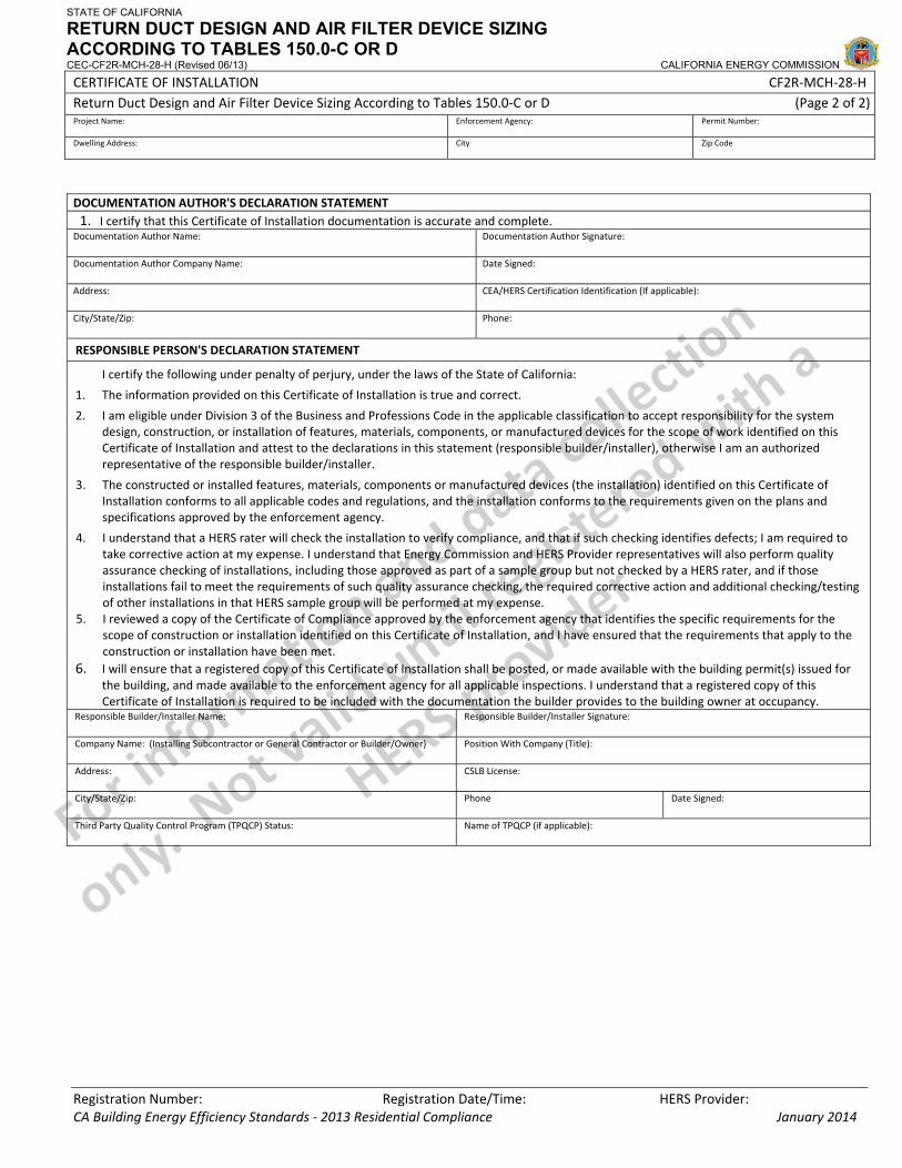
STATE OF CALIFORNIA
RETURN DUCT DESIGN AND AIR FILTER DEVICE SIZING ACCORDING TO TABLES 150.0-C OR D CEC-CF2R-MCH-28-H (Revised 06/13) CALIFORNIA ENERGY COMMISSION
CERTIFICATE OF INSTALLATION CF2R‐MCH‐28‐H Return Duct Design and Air Filter Device Sizing According to Tables 150.0‐C or D (Page 2 of 2) Project Name: Enforcement Agency: Permit Number:
Dwelling Address: City Zip Code
Registration Number: Registration Date/Time: HERS Provider: CA Building Energy Efficiency Standards ‐ 2013 Residential Compliance January 2014
DOCUMENTATION AUTHOR'S DECLARATION STATEMENT1. I certify that this Certificate of Installation documentation is accurate and complete.
Documentation Author Name: Documentation Author Signature:
Documentation Author Company Name: Date Signed:
Address: CEA/HERS Certification Identification (If applicable):
City/State/Zip: Phone:
RESPONSIBLE PERSON'S DECLARATION STATEMENT
I certify the following under penalty of perjury, under the laws of the State of California:
1. The information provided on this Certificate of Installation is true and correct.
2. I am eligible under Division 3 of the Business and Professions Code in the applicable classification to accept responsibility for the system design, construction, or installation of features, materials, components, or manufactured devices for the scope of work identified on this Certificate of Installation and attest to the declarations in this statement (responsible builder/installer), otherwise I am an authorized representative of the responsible builder/installer.
3. The constructed or installed features, materials, components or manufactured devices (the installation) identified on this Certificate of Installation conforms to all applicable codes and regulations, and the installation conforms to the requirements given on the plans and specifications approved by the enforcement agency.
4. I understand that a HERS rater will check the installation to verify compliance, and that if such checking identifies defects; I am required to take corrective action at my expense. I understand that Energy Commission and HERS Provider representatives will also perform quality assurance checking of installations, including those approved as part of a sample group but not checked by a HERS rater, and if those installations fail to meet the requirements of such quality assurance checking, the required corrective action and additional checking/testing of other installations in that HERS sample group will be performed at my expense.
5. I reviewed a copy of the Certificate of Compliance approved by the enforcement agency that identifies the specific requirements for the scope of construction or installation identified on this Certificate of Installation, and I have ensured that the requirements that apply to the construction or installation have been met.
6. I will ensure that a registered copy of this Certificate of Installation shall be posted, or made available with the building permit(s) issued for the building, and made available to the enforcement agency for all applicable inspections. I understand that a registered copy of this Certificate of Installation is required to be included with the documentation the builder provides to the building owner at occupancy.
Responsible Builder/Installer Name: Responsible Builder/Installer Signature:
Company Name: (Installing Subcontractor or General Contractor or Builder/Owner) Position With Company (Title):
Address: CSLB License:
City/State/Zip: Phone Date Signed:
Third Party Quality Control Program (TPQCP) Status: Name of TPQCP (if applicable):
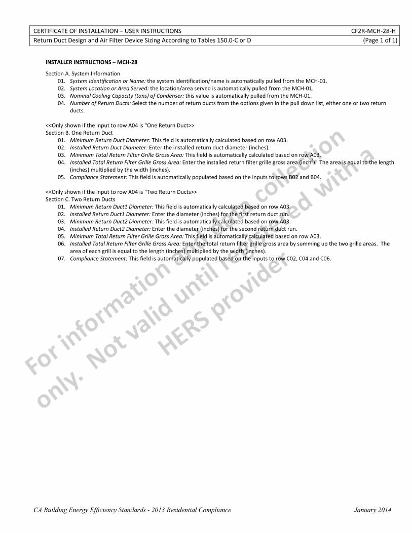
CERTIFICATE OF INSTALLATION – USER INSTRUCTIONS CF2R‐MCH‐28‐H Return Duct Design and Air Filter Device Sizing According to Tables 150.0‐C or D (Page 1 of 1)
CA Building Energy Efficiency Standards - 2013 Residential Compliance January 2014
INSTALLER INSTRUCTIONS – MCH‐28
Section A. System Information 01. System Identification or Name: the system identification/name is automatically pulled from the MCH‐01. 02. System Location or Area Served: the location/area served is automatically pulled from the MCH‐01. 03. Nominal Cooling Capacity (tons) of Condenser: this value is automatically pulled from the MCH‐01. 04. Number of Return Ducts: Select the number of return ducts from the options given in the pull down list, either one or two return
ducts. <<Only shown if the input to row A04 is “One Return Duct>> Section B. One Return Duct
01. Minimum Return Duct Diameter: This field is automatically calculated based on row A03. 02. Installed Return Duct Diameter: Enter the installed return duct diameter (inches). 03. Minimum Total Return Filter Grille Gross Area: This field is automatically calculated based on row A03. 04. Installed Total Return Filter Grille Gross Area: Enter the installed return filter grille gross area (inch2). The area is equal to the length
(inches) multiplied by the width (inches). 05. Compliance Statement: This field is automatically populated based on the inputs to rows B02 and B04.
<<Only shown if the input to row A04 is “Two Return Ducts>> Section C. Two Return Ducts
01. Minimum Return Duct1 Diameter: This field is automatically calculated based on row A03. 02. Installed Return Duct1 Diameter: Enter the diameter (inches) for the first return duct run. 03. Minimum Return Duct2 Diameter: This field is automatically calculated based on row A03. 04. Installed Return Duct2 Diameter: Enter the diameter (inches) for the second return duct run. 05. Minimum Total Return Filter Grille Gross Area: This field is automatically calculated based on row A03. 06. Installed Total Return Filter Grille Gross Area: Enter the total return filter grille gross area by summing up the two grille areas. The
area of each grill is equal to the length (inches) multiplied by the width (inches). 07. Compliance Statement: This field is automatically populated based on the inputs to row C02, C04 and C06.
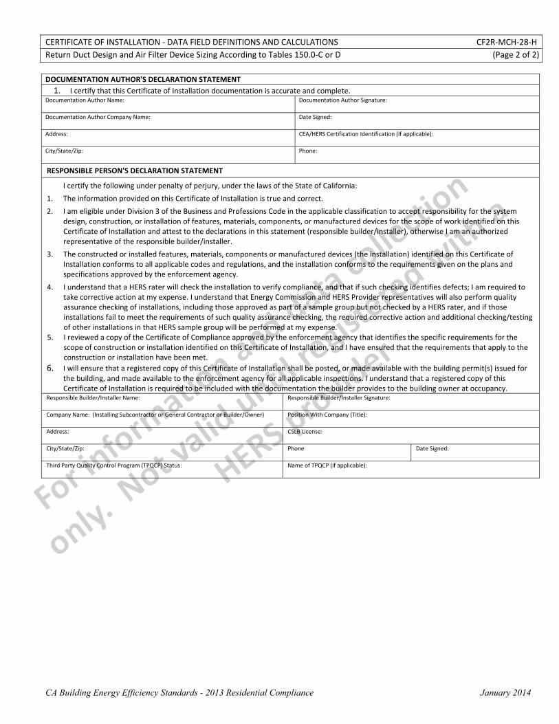
CERTIFICATE OF INSTALLATION ‐ DATA FIELD DEFINITIONS AND CALCULATIONS CF2R‐MCH‐28‐H Return Duct Design and Air Filter Device Sizing According to Tables 150.0‐C or D (Page 2 of 2)
CA Building Energy Efficiency Standards - 2013 Residential Compliance January 2014
DOCUMENTATION AUTHOR'S DECLARATION STATEMENT1. I certify that this Certificate of Installation documentation is accurate and complete.
Documentation Author Name: Documentation Author Signature:
Documentation Author Company Name: Date Signed:
Address: CEA/HERS Certification Identification (If applicable):
City/State/Zip: Phone:
RESPONSIBLE PERSON'S DECLARATION STATEMENT
I certify the following under penalty of perjury, under the laws of the State of California:
1. The information provided on this Certificate of Installation is true and correct.
2. I am eligible under Division 3 of the Business and Professions Code in the applicable classification to accept responsibility for the system design, construction, or installation of features, materials, components, or manufactured devices for the scope of work identified on this Certificate of Installation and attest to the declarations in this statement (responsible builder/installer), otherwise I am an authorized representative of the responsible builder/installer.
3. The constructed or installed features, materials, components or manufactured devices (the installation) identified on this Certificate of Installation conforms to all applicable codes and regulations, and the installation conforms to the requirements given on the plans and specifications approved by the enforcement agency.
4. I understand that a HERS rater will check the installation to verify compliance, and that if such checking identifies defects; I am required to take corrective action at my expense. I understand that Energy Commission and HERS Provider representatives will also perform quality assurance checking of installations, including those approved as part of a sample group but not checked by a HERS rater, and if those installations fail to meet the requirements of such quality assurance checking, the required corrective action and additional checking/testing of other installations in that HERS sample group will be performed at my expense.
5. I reviewed a copy of the Certificate of Compliance approved by the enforcement agency that identifies the specific requirements for the scope of construction or installation identified on this Certificate of Installation, and I have ensured that the requirements that apply to the construction or installation have been met.
6. I will ensure that a registered copy of this Certificate of Installation shall be posted, or made available with the building permit(s) issued for the building, and made available to the enforcement agency for all applicable inspections. I understand that a registered copy of this Certificate of Installation is required to be included with the documentation the builder provides to the building owner at occupancy.
Responsible Builder/Installer Name: Responsible Builder/Installer Signature:
Company Name: (Installing Subcontractor or General Contractor or Builder/Owner) Position With Company (Title):
Address: CSLB License:
City/State/Zip: Phone Date Signed:
Third Party Quality Control Program (TPQCP) Status: Name of TPQCP (if applicable):
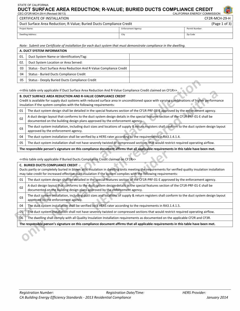
STATE OF CALIFORNIA
DUCT SURFACE AREA REDUCTION; R-VALUE; BURIED DUCTS COMPLIANCE CREDIT CEC-CF2R-MCH-29-H (Revised 06/13) CALIFORNIA ENERGY COMMISSION
CERTIFICATE OF INSTALLATION CF2R‐MCH‐29‐H Duct Surface Area Reduction; R‐Value; Buried Ducts Compliance Credit (Page 1 of 3)Project Name: Enforcement Agency: Permit Number:
Dwelling Address: City Zip Code
Registration Number: Registration Date/Time: HERS Provider: CA Building Energy Efficiency Standards ‐ 2013 Residential Compliance January 2014
Note: Submit one Certificate of installation for each duct system that must demonstrate compliance in the dwelling.
A. DUCT SYSTEM INFORMATION
01. Duct System Name or Identification/Tag:
02. Duct System Location or Area Served:
03 Status ‐ Duct Surface Area Reduction And R‐Value Compliance Credit
04 Status ‐ Buried Ducts Compliance Credit
05 Status ‐ Deeply Buried Ducts Compliance Credit
<<this table only applicable if Duct Surface Area Reduction And R‐Value Compliance Credit claimed on CF1R>>
B. DUCT SURFACE AREA REDUCTION AND R‐VALUE COMPLIANCE CREDIT Credit is available for supply duct systems with reduced surface area in unconditioned space with varying combinations of higher performance insulation if the system complies with the following requirements:
01 The duct system design shall be detailed in the special features section of the CF1R‐PRF‐01‐E approved by the enforcement agency.
02 A duct design layout that conforms to the duct system design details in the special features section of the CF1R‐PRF‐01‐E shall be documented on the building design plans approved by the enforcement agency.
03 The duct system installation, including duct sizes and locations of supply & return registers shall conform to the duct system design layout approved by the enforcement agency.
04 The duct system installation shall be verified by a HERS rater according to the requirements in RA3.1.4.1.4.
05 The duct system installation shall not have severely twisted or compressed sections that would restrict required operating airflow.
The responsible person’s signature on this compliance document affirms that all applicable requirements in this table have been met.
<<this table only applicable if Buried Ducts Compliance Credit claimed on CF1R>>
C. BURIED DUCTS COMPLIANCE CREDIT Ducts partly or completely buried in blown attic insulation in dwelling units meeting the requirements for verified quality insulation installation may take credit for increased effective duct insulation if the system complies with the following requirements:
01 The duct system design shall be detailed in the special features section of the CF1R‐PRF‐01‐E approved by the enforcement agency.
02 A duct design layout that conforms to the duct system design details in the special features section of the CF1R‐PRF‐01‐E shall be documented on the building design plans approved by the enforcement agency.
03 The duct system installation, including duct sizes and locations of supply & return registers shall conform to the duct system design layout approved by the enforcement agency.
04 The duct system installation shall be verified by a HERS rater according to the requirements in RA3.1.4.1.5.
05 The duct system installation shall not have severely twisted or compressed sections that would restrict required operating airflow.
06 The dwelling shall comply with all Quality Insulation Installation requirements as documented on the applicable CF2R and CF3R.
The responsible person’s signature on this compliance document affirms that all applicable requirements in this table have been met.
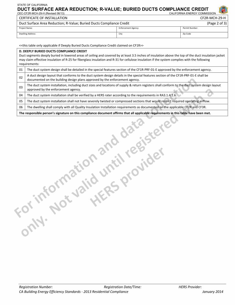
STATE OF CALIFORNIA
DUCT SURFACE AREA REDUCTION; R-VALUE; BURIED DUCTS COMPLIANCE CREDIT CEC-CF2R-MCH-29-H (Revised 06/13) CALIFORNIA ENERGY COMMISSION
CERTIFICATE OF INSTALLATION CF2R‐MCH‐29‐H Duct Surface Area Reduction; R‐Value; Buried Ducts Compliance Credit (Page 2 of 3)Project Name: Enforcement Agency: Permit Number:
Dwelling Address: City Zip Code
Registration Number: Registration Date/Time: HERS Provider: CA Building Energy Efficiency Standards ‐ 2013 Residential Compliance January 2014
<<this table only applicable if Deeply Buried Ducts Compliance Credit claimed on CF1R>>
D. DEEPLY BURIED DUCTS COMPLIANCE CREDIT Duct segments deeply buried in lowered areas of ceiling and covered by at least 3.5 inches of insulation above the top of the duct insulation jacket may claim effective insulation of R‐25 for fiberglass insulation and R‐31 for cellulose insulation if the system complies with the following requirements:
01 The duct system design shall be detailed in the special features section of the CF1R‐PRF‐01‐E approved by the enforcement agency.
02 A duct design layout that conforms to the duct system design details in the special features section of the CF1R‐PRF‐01‐E shall be documented on the building design plans approved by the enforcement agency.
03 The duct system installation, including duct sizes and locations of supply & return registers shall conform to the duct system design layout approved by the enforcement agency.
04 The duct system installation shall be verified by a HERS rater according to the requirements in RA3.1.4.1.6.
05 The duct system installation shall not have severely twisted or compressed sections that would restrict required operating airflow.
06 The dwelling shall comply with all Quality Insulation Installation requirements as documented on the applicable CF2R and CF3R.
The responsible person’s signature on this compliance document affirms that all applicable requirements in this table have been met.
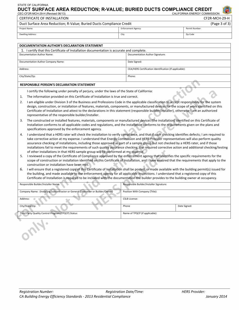
STATE OF CALIFORNIA
DUCT SURFACE AREA REDUCTION; R-VALUE; BURIED DUCTS COMPLIANCE CREDIT CEC-CF2R-MCH-29-H (Revised 06/13) CALIFORNIA ENERGY COMMISSION
CERTIFICATE OF INSTALLATION CF2R‐MCH‐29‐H Duct Surface Area Reduction; R‐Value; Buried Ducts Compliance Credit (Page 3 of 3)Project Name: Enforcement Agency: Permit Number:
Dwelling Address: City Zip Code
Registration Number: Registration Date/Time: HERS Provider: CA Building Energy Efficiency Standards ‐ 2013 Residential Compliance January 2014
DOCUMENTATION AUTHOR'S DECLARATION STATEMENT1. I certify that this Certificate of Installation documentation is accurate and complete.
Documentation Author Name: Documentation Author Signature:
Documentation Author Company Name: Date Signed:
Address: CEA/HERS Certification Identification (If applicable):
City/State/Zip: Phone:
RESPONSIBLE PERSON'S DECLARATION STATEMENT
I certify the following under penalty of perjury, under the laws of the State of California:
1. The information provided on this Certificate of Installation is true and correct.
2. I am eligible under Division 3 of the Business and Professions Code in the applicable classification to accept responsibility for the system design, construction, or installation of features, materials, components, or manufactured devices for the scope of work identified on this Certificate of Installation and attest to the declarations in this statement (responsible builder/installer), otherwise I am an authorized representative of the responsible builder/installer.
3. The constructed or installed features, materials, components or manufactured devices (the installation) identified on this Certificate of Installation conforms to all applicable codes and regulations, and the installation conforms to the requirements given on the plans and specifications approved by the enforcement agency.
4. I understand that a HERS rater will check the installation to verify compliance, and that if such checking identifies defects; I am required to take corrective action at my expense. I understand that Energy Commission and HERS Provider representatives will also perform quality assurance checking of installations, including those approved as part of a sample group but not checked by a HERS rater, and if those installations fail to meet the requirements of such quality assurance checking, the required corrective action and additional checking/testing of other installations in that HERS sample group will be performed at my expense.
5. I reviewed a copy of the Certificate of Compliance approved by the enforcement agency that identifies the specific requirements for the scope of construction or installation identified on this Certificate of Installation, and I have ensured that the requirements that apply to the construction or installation have been met.
6. I will ensure that a registered copy of this Certificate of Installation shall be posted, or made available with the building permit(s) issued for the building, and made available to the enforcement agency for all applicable inspections. I understand that a registered copy of this Certificate of Installation is required to be included with the documentation the builder provides to the building owner at occupancy.
Responsible Builder/Installer Name: Responsible Builder/Installer Signature:
Company Name: (Installing Subcontractor or General Contractor or Builder/Owner) Position With Company (Title):
Address: CSLB License:
City/State/Zip: Phone Date Signed:
Third Party Quality Control Program (TPQCP) Status: Name of TPQCP (if applicable):
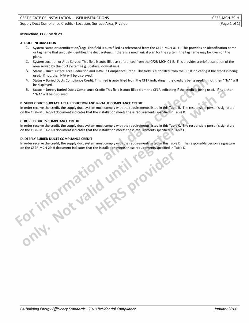
CERTIFICATE OF INSTALLATION ‐ USER INSTRUCTIONS CF2R‐MCH‐29‐H Supply Duct Compliance Credits ‐ Location; Surface Area; R‐value (Page 1 of 1)
CA Building Energy Efficiency Standards ‐ 2013 Residential Compliance January 2014
Instructions CF2R‐Mech 29 A. DUCT INFORMATION
1. System Name or Identification/Tag: This field is auto filled as referenced from the CF2R‐MCH‐01‐E. This provides an identification name or tag name that uniquely identifies the duct system. If there is a mechanical plan for the system, the tag name may be given on the plans.
2. System Location or Area Served: This field is auto filled as referenced from the CF2R‐MCH‐01‐E. This provides a brief description of the area served by the duct system (e.g. upstairs; downstairs).
3. Status – Duct Surface Area Reduction and R‐Value Compliance Credit: This field is auto filled from the CF1R indicating if the credit is being used. If not, then N/A will be displayed.
4. Status – Buried Ducts Compliance Credit: This filed is auto filled from the CF1R indicating if the credit is being used. If not, then “N/A” will be displayed.
5. Status – Deeply Buried Ducts Compliance Credit: This field is auto filled from the CF1R indicating if the credit is being used. If not, then “N/A” will be displayed.
B. SUPPLY DUCT SURFACE AREA REDUCTION AND R‐VALUE COMPLIANCE CREDIT In order receive the credit, the supply duct system must comply with the requirements listed in this Table B. The responsible person’s signature on the CF2R‐MCH‐29‐H document indicates that the installation meets these requirements specified in Table B. C. BURIED DUCTS COMPLIANCE CREDIT In order receive the credit, the supply duct system must comply with the requirements listed in this Table C. The responsible person’s signature on the CF2R‐MCH‐29‐H document indicates that the installation meets these requirements specified in Table C. D. DEEPLY BURIED DUCTS COMPLIANCE CREDIT In order receive the credit, the supply duct system must comply with the requirements listed in this Table D. The responsible person’s signature on the CF2R‐MCH‐29‐H document indicates that the installation meets these requirements specified in Table D.
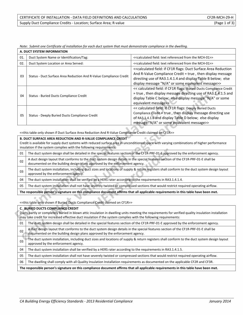
CERTIFICATE OF INSTALLATION ‐ DATA FIELD DEFINITIONS AND CALCULATIONS CF2R‐MCH‐29‐H Supply Duct Compliance Credits ‐ Location; Surface Area; R‐value (Page 1 of 3)
CA Building Energy Efficiency Standards ‐ 2013 Residential Compliance January 2014
Note: Submit one Certificate of installation for each duct system that must demonstrate compliance in the dwelling.
A. DUCT SYSTEM INFORMATION
01. Duct System Name or Identification/Tag: <<calculated field: text referenced from the MCH‐01>>
02. Duct System Location or Area Served: <<calculated field: text referenced from the MCH‐01>>
03 Status ‐ Duct Surface Area Reduction And R‐Value Compliance Credit
<<calculated field: if CF1R flags: Duct Surface Area Reduction And R‐Value Compliance Credit = true , then display message directing use of RA3.1.4.1.4 and display Table B below; else display message "N/A" or some equivalent message>>
04 Status ‐ Buried Ducts Compliance Credit
<< calculated field: if CF1R flags: Buried Ducts Compliance Credit= true , then display message directing use of RA3.1.4.1.5 and display Table C below; else display message "N/A" or some equivalent message>>
05 Status ‐ Deeply Buried Ducts Compliance Credit
<< calculated field: if CF1R flags: Deeply Buried Ducts Compliance Credit = true , then display message directing use of RA3.1.4.1.6 and display Table D below; else display message "N/A" or some equivalent message>>
<<this table only shown if Duct Surface Area Reduction And R‐Value Compliance Credit claimed on CF1R>>
B. DUCT SURFACE AREA REDUCTION AND R‐VALUE COMPLIANCE CREDIT Credit is available for supply duct systems with reduced surface area in unconditioned space with varying combinations of higher performance insulation if the system complies with the following requirements:
01 The duct system design shall be detailed in the special features section of the CF1R‐PRF‐01‐E approved by the enforcement agency.
02 A duct design layout that conforms to the duct system design details in the special features section of the CF1R‐PRF‐01‐E shall be documented on the building design plans approved by the enforcement agency.
03 The duct system installation, including duct sizes and locations of supply & return registers shall conform to the duct system design layout approved by the enforcement agency.
04 The duct system installation shall be verified by a HERS rater according to the requirements in RA3.1.4.1.4.
05 The duct system installation shall not have severely twisted or compressed sections that would restrict required operating airflow.
The responsible person’s signature on this compliance document affirms that all applicable requirements in this table have been met.
<<this table only shown if Buried Ducts Compliance Credit claimed on CF1R>>
C. BURIED DUCTS COMPLIANCE CREDIT Ducts partly or completely buried in blown attic insulation in dwelling units meeting the requirements for verified quality insulation installation may take credit for increased effective duct insulation if the system complies with the following requirements:
01 The duct system design shall be detailed in the special features section of the CF1R‐PRF‐01‐E approved by the enforcement agency.
02 A duct design layout that conforms to the duct system design details in the special features section of the CF1R‐PRF‐01‐E shall be documented on the building design plans approved by the enforcement agency.
03 The duct system installation, including duct sizes and locations of supply & return registers shall conform to the duct system design layout approved by the enforcement agency.
04 The duct system installation shall be verified by a HERS rater according to the requirements in RA3.1.4.1.5.
05 The duct system installation shall not have severely twisted or compressed sections that would restrict required operating airflow.
06 The dwelling shall comply with all Quality Insulation Installation requirements as documented on the applicable CF2R and CF3R.
The responsible person’s signature on this compliance document affirms that all applicable requirements in this table have been met.
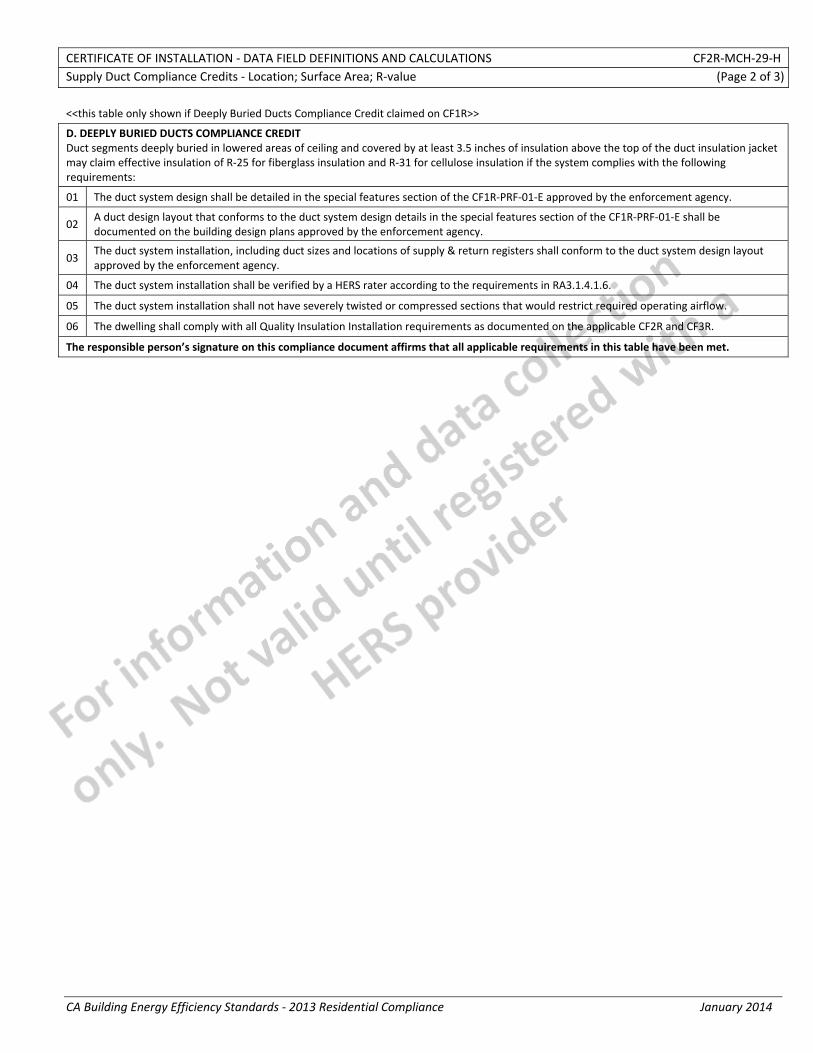
CERTIFICATE OF INSTALLATION ‐ DATA FIELD DEFINITIONS AND CALCULATIONS CF2R‐MCH‐29‐H Supply Duct Compliance Credits ‐ Location; Surface Area; R‐value (Page 2 of 3)
CA Building Energy Efficiency Standards ‐ 2013 Residential Compliance January 2014
<<this table only shown if Deeply Buried Ducts Compliance Credit claimed on CF1R>>
D. DEEPLY BURIED DUCTS COMPLIANCE CREDIT Duct segments deeply buried in lowered areas of ceiling and covered by at least 3.5 inches of insulation above the top of the duct insulation jacket may claim effective insulation of R‐25 for fiberglass insulation and R‐31 for cellulose insulation if the system complies with the following requirements:
01 The duct system design shall be detailed in the special features section of the CF1R‐PRF‐01‐E approved by the enforcement agency.
02 A duct design layout that conforms to the duct system design details in the special features section of the CF1R‐PRF‐01‐E shall be documented on the building design plans approved by the enforcement agency.
03 The duct system installation, including duct sizes and locations of supply & return registers shall conform to the duct system design layout approved by the enforcement agency.
04 The duct system installation shall be verified by a HERS rater according to the requirements in RA3.1.4.1.6.
05 The duct system installation shall not have severely twisted or compressed sections that would restrict required operating airflow.
06 The dwelling shall comply with all Quality Insulation Installation requirements as documented on the applicable CF2R and CF3R.
The responsible person’s signature on this compliance document affirms that all applicable requirements in this table have been met.

CERTIFICATE OF INSTALLATION ‐ DATA FIELD DEFINITIONS AND CALCULATIONS CF2R‐MCH‐29‐H Supply Duct Compliance Credits ‐ Location; Surface Area; R‐value (Page 3 of 3)
CA Building Energy Efficiency Standards ‐ 2013 Residential Compliance January 2014
DOCUMENTATION AUTHOR'S DECLARATION STATEMENT1. I certify that this Certificate of Installation documentation is accurate and complete.
Documentation Author Name: Documentation Author Signature:
Documentation Author Company Name: Date Signed:
Address: CEA/HERS Certification Identification (If applicable):
City/State/Zip: Phone:
RESPONSIBLE PERSON'S DECLARATION STATEMENT
I certify the following under penalty of perjury, under the laws of the State of California:
1. The information provided on this Certificate of Installation is true and correct.
2. I am eligible under Division 3 of the Business and Professions Code in the applicable classification to accept responsibility for the system design, construction, or installation of features, materials, components, or manufactured devices for the scope of work identified on this Certificate of Installation and attest to the declarations in this statement (responsible builder/installer), otherwise I am an authorized representative of the responsible builder/installer.
3. The constructed or installed features, materials, components or manufactured devices (the installation) identified on this Certificate of Installation conforms to all applicable codes and regulations, and the installation conforms to the requirements given on the plans and specifications approved by the enforcement agency.
4. I understand that a HERS rater will check the installation to verify compliance, and that if such checking identifies defects; I am required to take corrective action at my expense. I understand that Energy Commission and HERS Provider representatives will also perform quality assurance checking of installations, including those approved as part of a sample group but not checked by a HERS rater, and if those installations fail to meet the requirements of such quality assurance checking, the required corrective action and additional checking/testing of other installations in that HERS sample group will be performed at my expense.
5. I reviewed a copy of the Certificate of Compliance approved by the enforcement agency that identifies the specific requirements for the scope of construction or installation identified on this Certificate of Installation, and I have ensured that the requirements that apply to the construction or installation have been met.
6. I will ensure that a registered copy of this Certificate of Installation shall be posted, or made available with the building permit(s) issued for the building, and made available to the enforcement agency for all applicable inspections. I understand that a registered copy of this Certificate of Installation is required to be included with the documentation the builder provides to the building owner at occupancy.
Responsible Builder/Installer Name: Responsible Builder/Installer Signature:
Company Name: (Installing Subcontractor or General Contractor or Builder/Owner) Position With Company (Title):
Address: CSLB License:
City/State/Zip: Phone Date Signed:
Third Party Quality Control Program (TPQCP) Status: Name of TPQCP (if applicable):
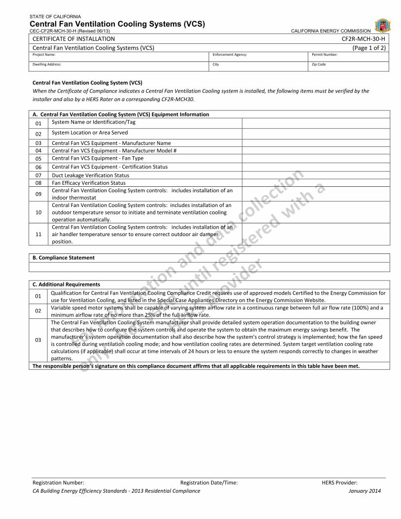
STATE OF CALIFORNIA
Central Fan Ventilation Cooling Systems (VCS) CEC-CF2R-MCH-30-H (Revised 06/13) CALIFORNIA ENERGY COMMISSION
CERTIFICATE OF INSTALLATION CF2R‐MCH‐30‐H Central Fan Ventilation Cooling Systems (VCS) (Page 1 of 2)Project Name: Enforcement Agency: Permit Number:
Dwelling Address: City Zip Code
Registration Number: Registration Date/Time: HERS Provider: CA Building Energy Efficiency Standards ‐ 2013 Residential Compliance January 2014
Central Fan Ventilation Cooling System (VCS) When the Certificate of Compliance indicates a Central Fan Ventilation Cooling system is installed, the following items must be verified by the installer and also by a HERS Rater on a corresponding CF2R‐MCH30.
A. Central Fan Ventilation Cooling System (VCS) Equipment Information
01 System Name or Identification/Tag
02 System Location or Area Served
03 Central Fan VCS Equipment ‐ Manufacturer Name 04 Central Fan VCS Equipment ‐ Manufacturer Model # 05 Central Fan VCS Equipment ‐ Fan Type
06 Central Fan VCS Equipment ‐ Certification Status 07 Duct Leakage Verification Status 08 Fan Efficacy Verification Status
09 Central Fan Ventilation Cooling System controls: includes installation of an indoor thermostat
10 Central Fan Ventilation Cooling System controls: includes installation of an outdoor temperature sensor to initiate and terminate ventilation cooling operation automatically.
11 Central Fan Ventilation Cooling System controls: includes installation of an air handler temperature sensor to ensure correct outdoor air damper position.
B. Compliance Statement
C. Additional Requirements
01 Qualification for Central Fan Ventilation Cooling Compliance Credit requires use of approved models Certified to the Energy Commission for use for Ventilation Cooling, and listed in the Special Case Appliances Directory on the Energy Commission Website.
02 Variable speed motor systems shall be capable of varying system airflow rate in a continuous range between full air flow rate (100%) and a minimum airflow rate of no more than 25% of the full airflow rate.
03
The Central Fan Ventilation Cooling System manufacturer shall provide detailed system operation documentation to the building owner that describes how to configure the system controls and operate the system to obtain the maximum energy savings benefit. The manufacturer's system operation documentation shall also describe how the system's control strategy is implemented; how the fan speed is controlled during ventilation cooling mode; and how ventilation cooling rates are determined. System target ventilation cooling rate calculations (if applicable) shall occur at time intervals of 24 hours or less to ensure the system responds correctly to changes in weather patterns.
The responsible person’s signature on this compliance document affirms that all applicable requirements in this table have been met.
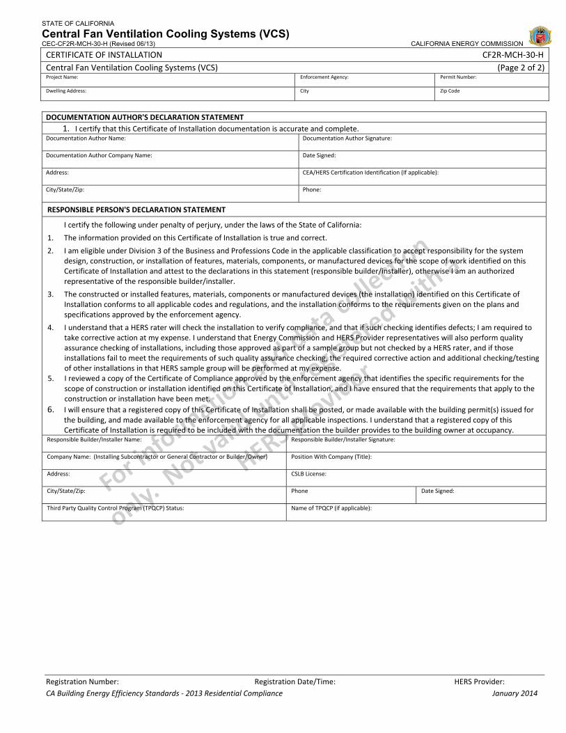
STATE OF CALIFORNIA
Central Fan Ventilation Cooling Systems (VCS) CEC-CF2R-MCH-30-H (Revised 06/13) CALIFORNIA ENERGY COMMISSION
CERTIFICATE OF INSTALLATION CF2R‐MCH‐30‐H Central Fan Ventilation Cooling Systems (VCS) (Page 2 of 2)Project Name: Enforcement Agency: Permit Number:
Dwelling Address: City Zip Code
Registration Number: Registration Date/Time: HERS Provider: CA Building Energy Efficiency Standards ‐ 2013 Residential Compliance January 2014
DOCUMENTATION AUTHOR'S DECLARATION STATEMENT1. I certify that this Certificate of Installation documentation is accurate and complete.
Documentation Author Name: Documentation Author Signature:
Documentation Author Company Name: Date Signed:
Address: CEA/HERS Certification Identification (If applicable):
City/State/Zip: Phone:
RESPONSIBLE PERSON'S DECLARATION STATEMENT
I certify the following under penalty of perjury, under the laws of the State of California:
1. The information provided on this Certificate of Installation is true and correct.
2. I am eligible under Division 3 of the Business and Professions Code in the applicable classification to accept responsibility for the system design, construction, or installation of features, materials, components, or manufactured devices for the scope of work identified on this Certificate of Installation and attest to the declarations in this statement (responsible builder/installer), otherwise I am an authorized representative of the responsible builder/installer.
3. The constructed or installed features, materials, components or manufactured devices (the installation) identified on this Certificate of Installation conforms to all applicable codes and regulations, and the installation conforms to the requirements given on the plans and specifications approved by the enforcement agency.
4. I understand that a HERS rater will check the installation to verify compliance, and that if such checking identifies defects; I am required to take corrective action at my expense. I understand that Energy Commission and HERS Provider representatives will also perform quality assurance checking of installations, including those approved as part of a sample group but not checked by a HERS rater, and if those installations fail to meet the requirements of such quality assurance checking, the required corrective action and additional checking/testing of other installations in that HERS sample group will be performed at my expense.
5. I reviewed a copy of the Certificate of Compliance approved by the enforcement agency that identifies the specific requirements for the scope of construction or installation identified on this Certificate of Installation, and I have ensured that the requirements that apply to the construction or installation have been met.
6. I will ensure that a registered copy of this Certificate of Installation shall be posted, or made available with the building permit(s) issued for the building, and made available to the enforcement agency for all applicable inspections. I understand that a registered copy of this Certificate of Installation is required to be included with the documentation the builder provides to the building owner at occupancy.
Responsible Builder/Installer Name: Responsible Builder/Installer Signature:
Company Name: (Installing Subcontractor or General Contractor or Builder/Owner) Position With Company (Title):
Address: CSLB License:
City/State/Zip: Phone Date Signed:
Third Party Quality Control Program (TPQCP) Status: Name of TPQCP (if applicable):
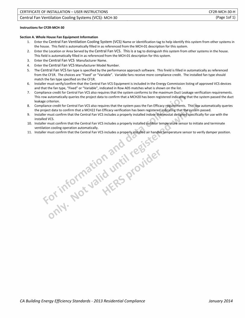
CERTIFICATE OF INSTALLATION – USER INSTRUCTIONS CF2R‐MCH‐30‐H
Central Fan Ventilation Cooling Systems (VCS)‐ MCH‐30 (Page 1of 1)
CA Building Energy Efficiency Standards ‐ 2013 Residential Compliance January 2014
Instructions for CF2R‐MCH‐30 Section A. Whole House Fan Equipment Information
1. Enter the Central Fan Ventilation Cooling System (VCS) Name or identification tag to help identify this system from other systems in the house. This field is automatically filled in as referenced from the MCH‐01 description for this system.
2. Enter the Location or Area Served by the Central Fan VCS. This is a tag to distinguish this system from other systems in the house. This field is automatically filled in as referenced from the MCH‐01 description for this system.
3. Enter the Central Fan VCS Manufacturer Name. 4. Enter the Central Fan VCS Manufacturer Model Number. 5. The Central Fan VCS fan type is specified by the performance approach software. This fireld is filled in automatically as referenced
from the CF1R. The choices are “Fixed” or “Variable”. Variable fans receive more compliance credit. The installed fan type should match the fan type specified on the CF1R.
6. Installer must verify/confirm that the Central Fan VCS Equipment is included in the Energy Commission listing of approved VCS devices and that the fan type, “Fixed” or “Variable”, indicated in Row A05 matches what is shown on the list.
7. Compliance credit for Central Fan VCS also requires that the system conforms to the maximum Duct Leakage verification requirements. This row automatically queries the project data to confirm that a MCH20 has been registered indicating that the system passed the duct leakage criterion.
8. Compliance credit for Central Fan VCS also requires that the system pass the Fan Efficacy requirements. This row automatically queries the project data to confirm that a MCH22 Fan Efficacy verification has been registered indicating that the system passed.
9. Installer must confirm that the Central Fan VCS includes a properly installed indoor thermostat designed specifically for use with the installed VCS.
10. Installer must confirm that the Central Fan VCS includes a properly installed outdoor temperature sensor to initiate and terminate ventilation cooling operation automatically.
11. Installer must confirm that the Central Fan VCS includes a properly installed air handler temperature sensor to verify damper position.
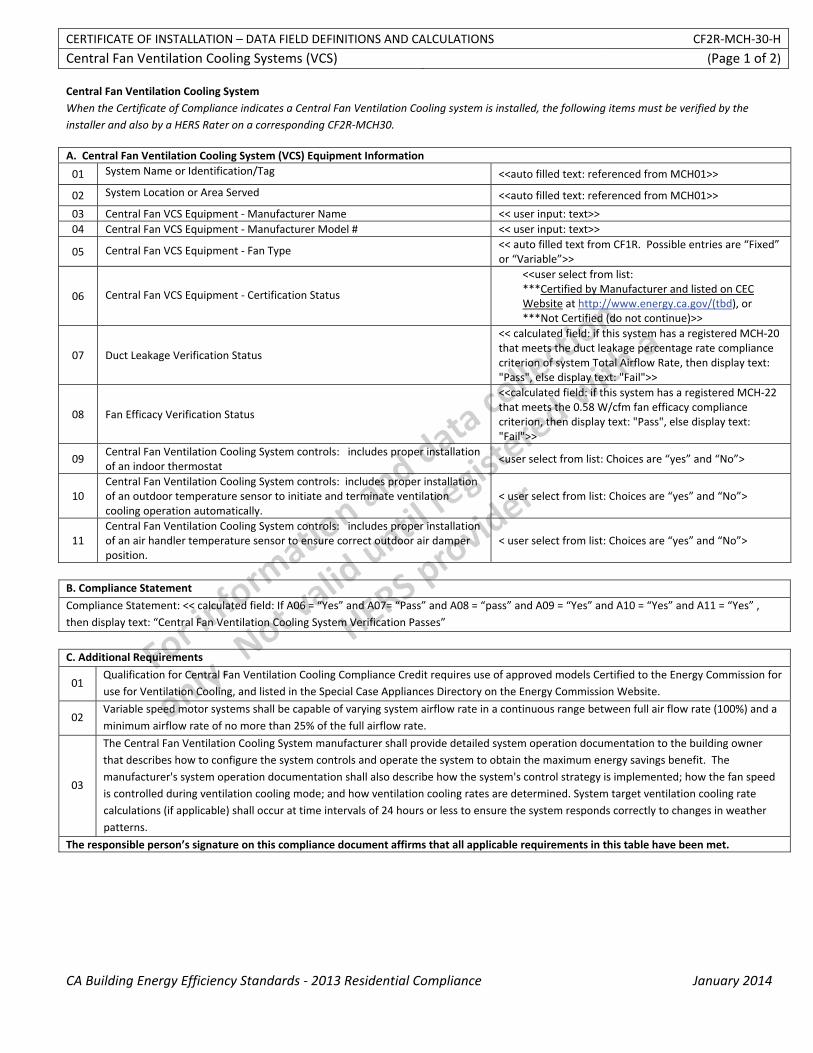
CERTIFICATE OF INSTALLATION – DATA FIELD DEFINITIONS AND CALCULATIONS CF2R‐MCH‐30‐H
Central Fan Ventilation Cooling Systems (VCS) (Page 1 of 2)
CA Building Energy Efficiency Standards ‐ 2013 Residential Compliance January 2014
Central Fan Ventilation Cooling System When the Certificate of Compliance indicates a Central Fan Ventilation Cooling system is installed, the following items must be verified by the installer and also by a HERS Rater on a corresponding CF2R‐MCH30.
A. Central Fan Ventilation Cooling System (VCS) Equipment Information
01 System Name or Identification/Tag <<auto filled text: referenced from MCH01>>
02 System Location or Area Served <<auto filled text: referenced from MCH01>>
03 Central Fan VCS Equipment ‐ Manufacturer Name << user input: text>> 04 Central Fan VCS Equipment ‐ Manufacturer Model # << user input: text>>
05 Central Fan VCS Equipment ‐ Fan Type << auto filled text from CF1R. Possible entries are “Fixed” or “Variable”>>
06 Central Fan VCS Equipment ‐ Certification Status
<<user select from list: ***Certified by Manufacturer and listed on CEC Website at http://www.energy.ca.gov/(tbd), or ***Not Certified (do not continue)>>
07 Duct Leakage Verification Status
<< calculated field: if this system has a registered MCH‐20 that meets the duct leakage percentage rate compliance criterion of system Total Airflow Rate, then display text: "Pass", else display text: "Fail">>
08 Fan Efficacy Verification Status
<<calculated field: if this system has a registered MCH‐22 that meets the 0.58 W/cfm fan efficacy compliance criterion, then display text: "Pass", else display text: "Fail">>
09 Central Fan Ventilation Cooling System controls: includes proper installation of an indoor thermostat
<user select from list: Choices are “yes” and “No”>
10 Central Fan Ventilation Cooling System controls: includes proper installation of an outdoor temperature sensor to initiate and terminate ventilation cooling operation automatically.
< user select from list: Choices are “yes” and “No”>
11 Central Fan Ventilation Cooling System controls: includes proper installation of an air handler temperature sensor to ensure correct outdoor air damper position.
< user select from list: Choices are “yes” and “No”>
B. Compliance Statement
Compliance Statement: << calculated field: If A06 = “Yes” and A07= “Pass” and A08 = “pass” and A09 = “Yes” and A10 = “Yes” and A11 = “Yes” , then display text: “Central Fan Ventilation Cooling System Verification Passes”
C. Additional Requirements
01 Qualification for Central Fan Ventilation Cooling Compliance Credit requires use of approved models Certified to the Energy Commission for use for Ventilation Cooling, and listed in the Special Case Appliances Directory on the Energy Commission Website.
02 Variable speed motor systems shall be capable of varying system airflow rate in a continuous range between full air flow rate (100%) and a minimum airflow rate of no more than 25% of the full airflow rate.
03
The Central Fan Ventilation Cooling System manufacturer shall provide detailed system operation documentation to the building owner that describes how to configure the system controls and operate the system to obtain the maximum energy savings benefit. The manufacturer's system operation documentation shall also describe how the system's control strategy is implemented; how the fan speed is controlled during ventilation cooling mode; and how ventilation cooling rates are determined. System target ventilation cooling rate calculations (if applicable) shall occur at time intervals of 24 hours or less to ensure the system responds correctly to changes in weather patterns.
The responsible person’s signature on this compliance document affirms that all applicable requirements in this table have been met.
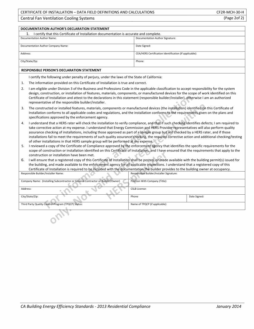
CERTIFICATE OF INSTALLATION – DATA FIELD DEFINITIONS AND CALCULATIONS CF2R‐MCH‐30‐H
Central Fan Ventilation Cooling Systems (Page 2of 2)
CA Building Energy Efficiency Standards ‐ 2013 Residential Compliance January 2014
DOCUMENTATION AUTHOR'S DECLARATION STATEMENT1. I certify that this Certificate of Installation documentation is accurate and complete.
Documentation Author Name: Documentation Author Signature:
Documentation Author Company Name: Date Signed:
Address: CEA/HERS Certification Identification (If applicable):
City/State/Zip: Phone:
RESPONSIBLE PERSON'S DECLARATION STATEMENT
I certify the following under penalty of perjury, under the laws of the State of California:
1. The information provided on this Certificate of Installation is true and correct.
2. I am eligible under Division 3 of the Business and Professions Code in the applicable classification to accept responsibility for the system design, construction, or installation of features, materials, components, or manufactured devices for the scope of work identified on this Certificate of Installation and attest to the declarations in this statement (responsible builder/installer), otherwise I am an authorized representative of the responsible builder/installer.
3. The constructed or installed features, materials, components or manufactured devices (the installation) identified on this Certificate of Installation conforms to all applicable codes and regulations, and the installation conforms to the requirements given on the plans and specifications approved by the enforcement agency.
4. I understand that a HERS rater will check the installation to verify compliance, and that if such checking identifies defects; I am required to take corrective action at my expense. I understand that Energy Commission and HERS Provider representatives will also perform quality assurance checking of installations, including those approved as part of a sample group but not checked by a HERS rater, and if those installations fail to meet the requirements of such quality assurance checking, the required corrective action and additional checking/testing of other installations in that HERS sample group will be performed at my expense.
5. I reviewed a copy of the Certificate of Compliance approved by the enforcement agency that identifies the specific requirements for the scope of construction or installation identified on this Certificate of Installation, and I have ensured that the requirements that apply to the construction or installation have been met.
6. I will ensure that a registered copy of this Certificate of Installation shall be posted, or made available with the building permit(s) issued for the building, and made available to the enforcement agency for all applicable inspections. I understand that a registered copy of this Certificate of Installation is required to be included with the documentation the builder provides to the building owner at occupancy.
Responsible Builder/Installer Name: Responsible Builder/Installer Signature:
Company Name: (Installing Subcontractor or General Contractor or Builder/Owner) Position With Company (Title):
Address: CSLB License:
City/State/Zip: Phone Date Signed:
Third Party Quality Control Program (TPQCP) Status: Name of TPQCP (if applicable):
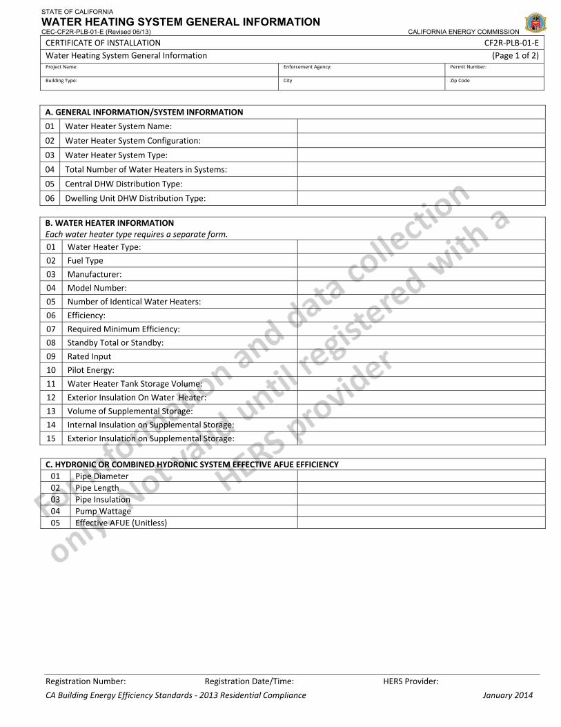
STATE OF CALIFORNIA
WATER HEATING SYSTEM GENERAL INFORMATION CEC-CF2R-PLB-01-E (Revised 06/13) CALIFORNIA ENERGY COMMISSION
CERTIFICATE OF INSTALLATION CF2R‐PLB‐01‐E Water Heating System General Information (Page 1 of 2) Project Name: Enforcement Agency: Permit Number:
Building Type: City Zip Code
Registration Number: Registration Date/Time: HERS Provider:
CA Building Energy Efficiency Standards ‐ 2013 Residential Compliance January 2014
A. GENERAL INFORMATION/SYSTEM INFORMATION
01 Water Heater System Name:
02 Water Heater System Configuration:
03 Water Heater System Type:
04 Total Number of Water Heaters in Systems:
05 Central DHW Distribution Type:
06 Dwelling Unit DHW Distribution Type: B. WATER HEATER INFORMATION Each water heater type requires a separate form. 01 Water Heater Type:
02 Fuel Type
03 Manufacturer:
04 Model Number:
05 Number of Identical Water Heaters:
06 Efficiency:
07 Required Minimum Efficiency:
08 Standby Total or Standby:
09 Rated Input
10 Pilot Energy:
11 Water Heater Tank Storage Volume:
12 Exterior Insulation On Water Heater:
13 Volume of Supplemental Storage:
14 Internal Insulation on Supplemental Storage:
15 Exterior Insulation on Supplemental Storage:
C. HYDRONIC OR COMBINED HYDRONIC SYSTEM EFFECTIVE AFUE EFFICIENCY01 Pipe Diameter 02 Pipe Length 03 Pipe Insulation 04 Pump Wattage 05 Effective AFUE (Unitless)
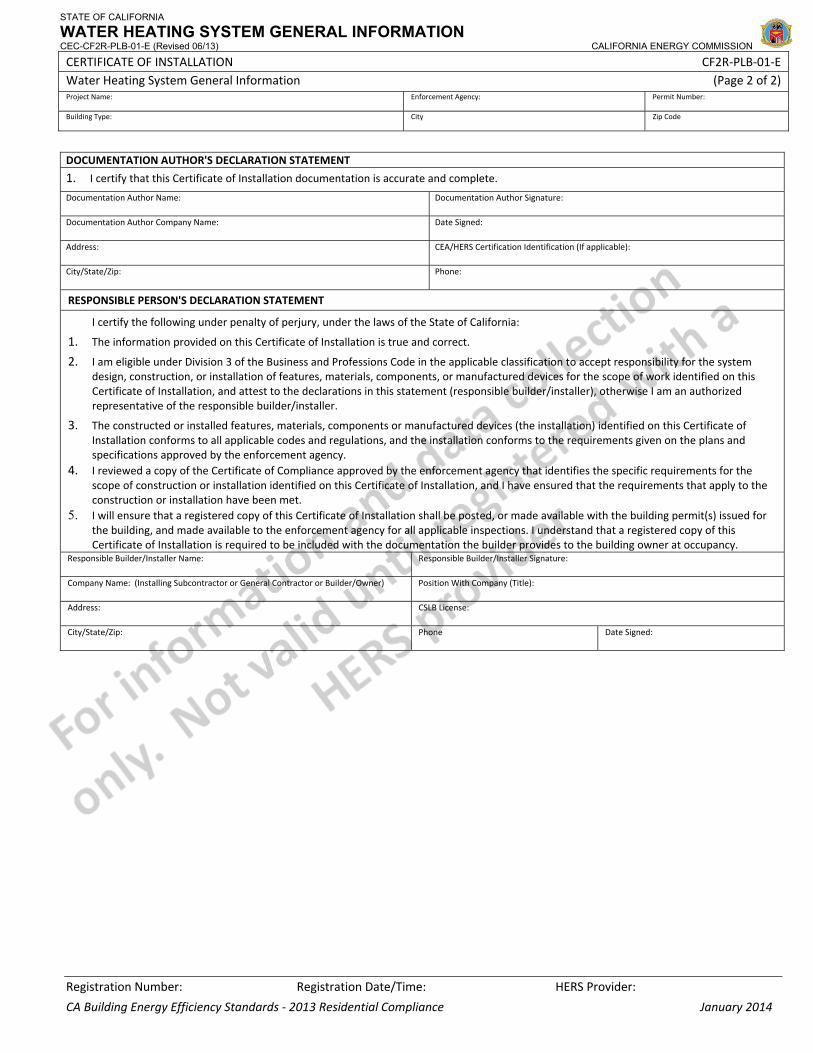
STATE OF CALIFORNIA
WATER HEATING SYSTEM GENERAL INFORMATION CEC-CF2R-PLB-01-E (Revised 06/13) CALIFORNIA ENERGY COMMISSION
CERTIFICATE OF INSTALLATION CF2R‐PLB‐01‐E Water Heating System General Information (Page 2 of 2) Project Name: Enforcement Agency: Permit Number:
Building Type: City Zip Code
Registration Number: Registration Date/Time: HERS Provider:
CA Building Energy Efficiency Standards ‐ 2013 Residential Compliance January 2014
DOCUMENTATION AUTHOR'S DECLARATION STATEMENT
1. I certify that this Certificate of Installation documentation is accurate and complete.
Documentation Author Name: Documentation Author Signature:
Documentation Author Company Name: Date Signed:
Address: CEA/HERS Certification Identification (If applicable):
City/State/Zip: Phone:
RESPONSIBLE PERSON'S DECLARATION STATEMENT
I certify the following under penalty of perjury, under the laws of the State of California:
1. The information provided on this Certificate of Installation is true and correct.
2. I am eligible under Division 3 of the Business and Professions Code in the applicable classification to accept responsibility for the system design, construction, or installation of features, materials, components, or manufactured devices for the scope of work identified on this Certificate of Installation, and attest to the declarations in this statement (responsible builder/installer), otherwise I am an authorized representative of the responsible builder/installer.
3. The constructed or installed features, materials, components or manufactured devices (the installation) identified on this Certificate of Installation conforms to all applicable codes and regulations, and the installation conforms to the requirements given on the plans and specifications approved by the enforcement agency.
4. I reviewed a copy of the Certificate of Compliance approved by the enforcement agency that identifies the specific requirements for the scope of construction or installation identified on this Certificate of Installation, and I have ensured that the requirements that apply to the construction or installation have been met.
5. I will ensure that a registered copy of this Certificate of Installation shall be posted, or made available with the building permit(s) issued for the building, and made available to the enforcement agency for all applicable inspections. I understand that a registered copy of this Certificate of Installation is required to be included with the documentation the builder provides to the building owner at occupancy.
Responsible Builder/Installer Name: Responsible Builder/Installer Signature:
Company Name: (Installing Subcontractor or General Contractor or Builder/Owner) Position With Company (Title):
Address: CSLB License:
City/State/Zip: Phone Date Signed:
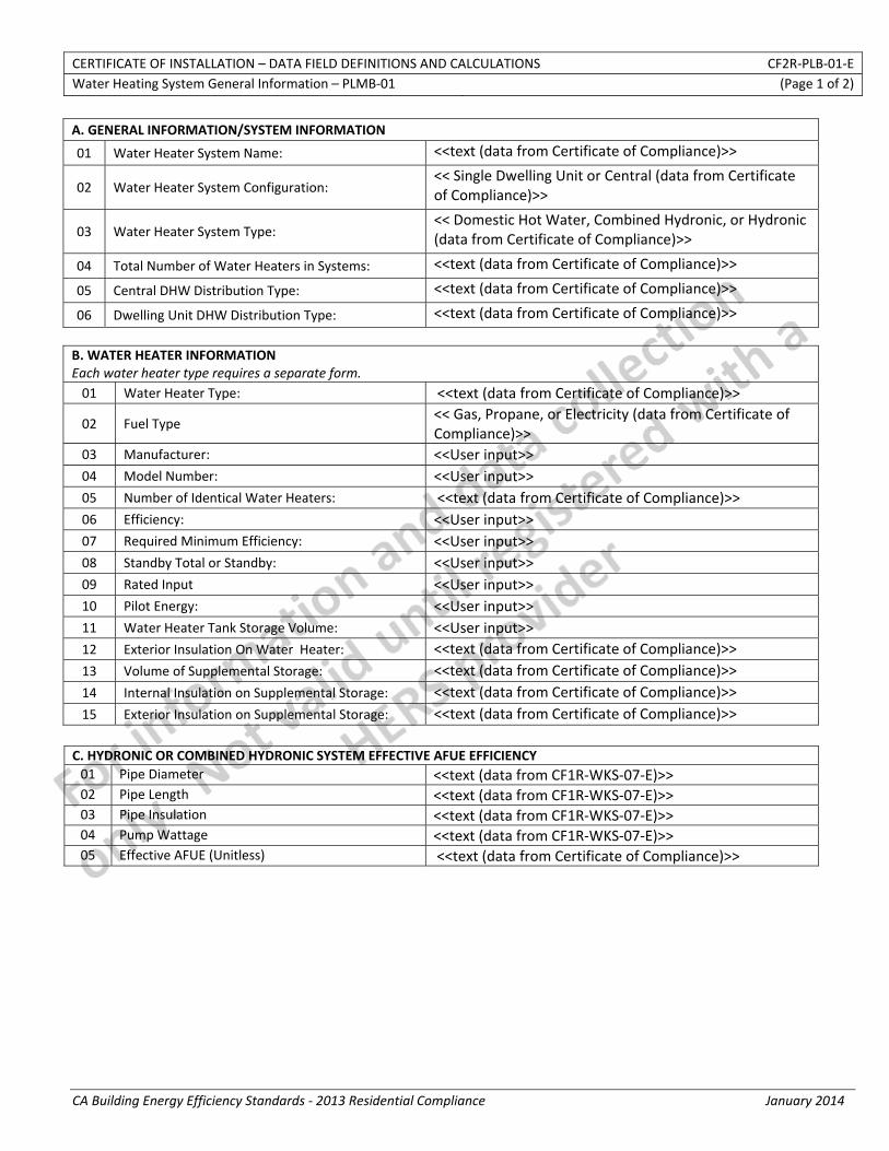
CERTIFICATE OF INSTALLATION – DATA FIELD DEFINITIONS AND CALCULATIONS CF2R‐PLB‐01‐E Water Heating System General Information – PLMB‐01 (Page 1 of 2)
CA Building Energy Efficiency Standards ‐ 2013 Residential Compliance January 2014
A. GENERAL INFORMATION/SYSTEM INFORMATION
01 Water Heater System Name: <<text (data from Certificate of Compliance)>>
02 Water Heater System Configuration: << Single Dwelling Unit or Central (data from Certificate of Compliance)>>
03 Water Heater System Type: << Domestic Hot Water, Combined Hydronic, or Hydronic (data from Certificate of Compliance)>>
04 Total Number of Water Heaters in Systems: <<text (data from Certificate of Compliance)>>
05 Central DHW Distribution Type: <<text (data from Certificate of Compliance)>>
06 Dwelling Unit DHW Distribution Type: <<text (data from Certificate of Compliance)>>
B. WATER HEATER INFORMATION Each water heater type requires a separate form. 01 Water Heater Type: <<text (data from Certificate of Compliance)>>
02 Fuel Type << Gas, Propane, or Electricity (data from Certificate of Compliance)>>
03 Manufacturer: <<User input>> 04 Model Number: <<User input>> 05 Number of Identical Water Heaters: <<text (data from Certificate of Compliance)>> 06 Efficiency: <<User input>> 07 Required Minimum Efficiency: <<User input>> 08 Standby Total or Standby: <<User input>> 09 Rated Input <<User input>> 10 Pilot Energy: <<User input>> 11 Water Heater Tank Storage Volume: <<User input>> 12 Exterior Insulation On Water Heater: <<text (data from Certificate of Compliance)>> 13 Volume of Supplemental Storage: <<text (data from Certificate of Compliance)>> 14 Internal Insulation on Supplemental Storage: <<text (data from Certificate of Compliance)>> 15 Exterior Insulation on Supplemental Storage: <<text (data from Certificate of Compliance)>>
C. HYDRONIC OR COMBINED HYDRONIC SYSTEM EFFECTIVE AFUE EFFICIENCY01 Pipe Diameter <<text (data from CF1R‐WKS‐07‐E)>> 02 Pipe Length <<text (data from CF1R‐WKS‐07‐E)>> 03 Pipe Insulation <<text (data from CF1R‐WKS‐07‐E)>> 04 Pump Wattage <<text (data from CF1R‐WKS‐07‐E)>> 05 Effective AFUE (Unitless) <<text (data from Certificate of Compliance)>>

CERTIFICATE OF INSTALLATION – DATA FIELD DEFINITIONS AND CALCULATIONS CF2R‐PLB‐01‐E Water Heating System General Information – PLMB‐01 (Page 2 of 2)
CA Building Energy Efficiency Standards ‐ 2013 Residential Compliance January 2014
DOCUMENTATION AUTHOR'S DECLARATION STATEMENT
1. I certify that this Certificate of Installation documentation is accurate and complete.
Documentation Author Name: Documentation Author Signature:
Documentation Author Company Name: Date Signed:
Address: CEA/HERS Certification Identification (If applicable):
City/State/Zip: Phone:
RESPONSIBLE PERSON'S DECLARATION STATEMENT
I certify the following under penalty of perjury, under the laws of the State of California:
1. The information provided on this Certificate of Installation is true and correct.
2. I am eligible under Division 3 of the Business and Professions Code in the applicable classification to accept responsibility for the system design, construction, or installation of features, materials, components, or manufactured devices for the scope of work identified on this Certificate of Installation, and attest to the declarations in this statement (responsible builder/installer), otherwise I am an authorized representative of the responsible builder/installer.
3. The constructed or installed features, materials, components or manufactured devices (the installation) identified on this Certificate of Installation conforms to all applicable codes and regulations, and the installation conforms to the requirements given on the plans and specifications approved by the enforcement agency.
4. I reviewed a copy of the Certificate of Compliance approved by the enforcement agency that identifies the specific requirements for the scope of construction or installation identified on this Certificate of Installation, and I have ensured that the requirements that apply to the construction or installation have been met.
5. I will ensure that a registered copy of this Certificate of Installation shall be posted, or made available with the building permit(s) issued for the building, and made available to the enforcement agency for all applicable inspections. I understand that a registered copy of this Certificate of Installation is required to be included with the documentation the builder provides to the building owner at occupancy.
Responsible Builder/Installer Name: Responsible Builder/Installer Signature:
Company Name: (Installing Subcontractor or General Contractor or Builder/Owner) Position With Company (Title):
Address: CSLB License:
City/State/Zip: Phone Date Signed:
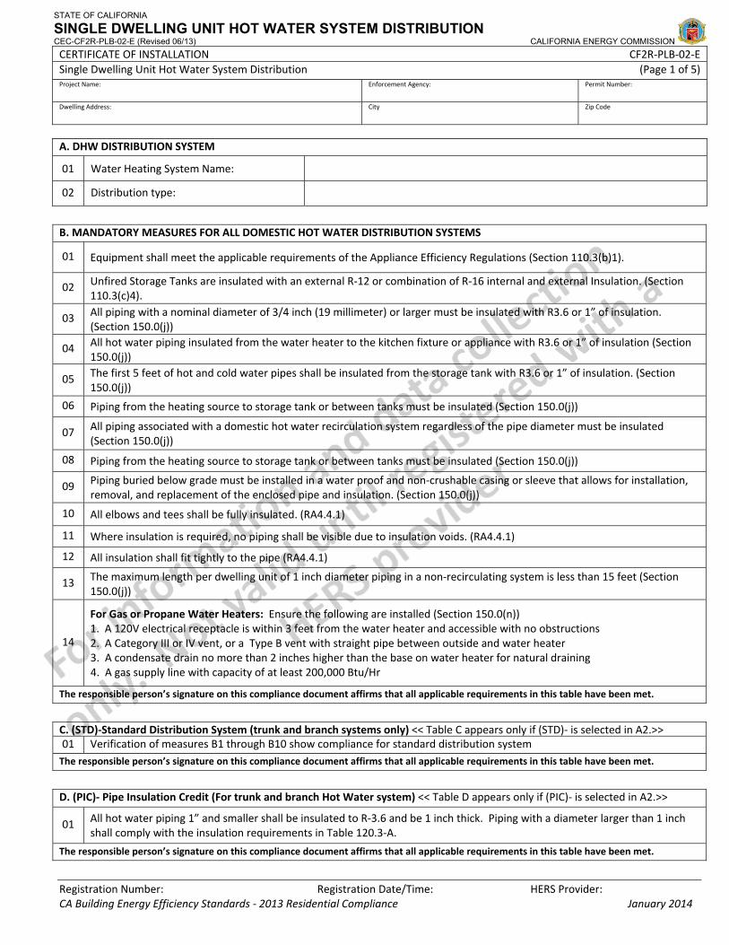
STATE OF CALIFORNIA
SINGLE DWELLING UNIT HOT WATER SYSTEM DISTRIBUTION CEC-CF2R-PLB-02-E (Revised 06/13) CALIFORNIA ENERGY COMMISSION CERTIFICATE OF INSTALLATION CF2R‐PLB‐02‐ESingle Dwelling Unit Hot Water System Distribution (Page 1 of 5)Project Name: Enforcement Agency: Permit Number:
Dwelling Address: City Zip Code
Registration Number: Registration Date/Time: HERS Provider: CA Building Energy Efficiency Standards ‐ 2013 Residential Compliance January 2014
A. DHW DISTRIBUTION SYSTEM
01 Water Heating System Name:
02 Distribution type:
B. MANDATORY MEASURES FOR ALL DOMESTIC HOT WATER DISTRIBUTION SYSTEMS
01 Equipment shall meet the applicable requirements of the Appliance Efficiency Regulations (Section 110.3(b)1).
02 Unfired Storage Tanks are insulated with an external R‐12 or combination of R‐16 internal and external Insulation. (Section 110.3(c)4).
03 All piping with a nominal diameter of 3/4 inch (19 millimeter) or larger must be insulated with R3.6 or 1” of insulation. (Section 150.0(j))
04 All hot water piping insulated from the water heater to the kitchen fixture or appliance with R3.6 or 1” of insulation (Section 150.0(j))
05 The first 5 feet of hot and cold water pipes shall be insulated from the storage tank with R3.6 or 1” of insulation. (Section 150.0(j))
06 Piping from the heating source to storage tank or between tanks must be insulated (Section 150.0(j))
07 All piping associated with a domestic hot water recirculation system regardless of the pipe diameter must be insulated (Section 150.0(j))
08 Piping from the heating source to storage tank or between tanks must be insulated (Section 150.0(j))
09 Piping buried below grade must be installed in a water proof and non‐crushable casing or sleeve that allows for installation, removal, and replacement of the enclosed pipe and insulation. (Section 150.0(j))
10 All elbows and tees shall be fully insulated. (RA4.4.1)
11 Where insulation is required, no piping shall be visible due to insulation voids. (RA4.4.1)
12 All insulation shall fit tightly to the pipe (RA4.4.1)
13 The maximum length per dwelling unit of 1 inch diameter piping in a non‐recirculating system is less than 15 feet (Section 150.0(j))
14
For Gas or Propane Water Heaters: Ensure the following are installed (Section 150.0(n)) 1. A 120V electrical receptacle is within 3 feet from the water heater and accessible with no obstructions 2. A Category III or IV vent, or a Type B vent with straight pipe between outside and water heater 3. A condensate drain no more than 2 inches higher than the base on water heater for natural draining 4. A gas supply line with capacity of at least 200,000 Btu/Hr
The responsible person’s signature on this compliance document affirms that all applicable requirements in this table have been met.
C. (STD)‐Standard Distribution System (trunk and branch systems only) << Table C appears only if (STD)‐ is selected in A2.>>01 Verification of measures B1 through B10 show compliance for standard distribution system The responsible person’s signature on this compliance document affirms that all applicable requirements in this table have been met.
D. (PIC)‐ Pipe Insulation Credit (For trunk and branch Hot Water system) << Table D appears only if (PIC)‐ is selected in A2.>>
01 All hot water piping 1” and smaller shall be insulated to R‐3.6 and be 1 inch thick. Piping with a diameter larger than 1 inch shall comply with the insulation requirements in Table 120.3‐A.
The responsible person’s signature on this compliance document affirms that all applicable requirements in this table have been met.
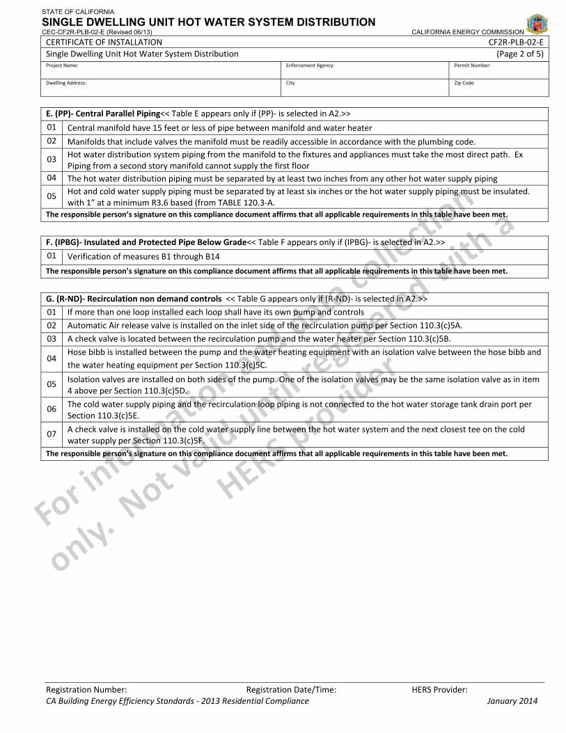
STATE OF CALIFORNIA
SINGLE DWELLING UNIT HOT WATER SYSTEM DISTRIBUTION CEC-CF2R-PLB-02-E (Revised 06/13) CALIFORNIA ENERGY COMMISSION CERTIFICATE OF INSTALLATION CF2R‐PLB‐02‐ESingle Dwelling Unit Hot Water System Distribution (Page 2 of 5)Project Name: Enforcement Agency: Permit Number:
Dwelling Address: City Zip Code
Registration Number: Registration Date/Time: HERS Provider: CA Building Energy Efficiency Standards ‐ 2013 Residential Compliance January 2014
E. (PP)‐ Central Parallel Piping<< Table E appears only if (PP)‐ is selected in A2.>>
01 Central manifold have 15 feet or less of pipe between manifold and water heater 02 Manifolds that include valves the manifold must be readily accessible in accordance with the plumbing code.
03 Hot water distribution system piping from the manifold to the fixtures and appliances must take the most direct path. Ex Piping from a second story manifold cannot supply the first floor
04 The hot water distribution piping must be separated by at least two inches from any other hot water supply piping
05 Hot and cold water supply piping must be separated by at least six inches or the hot water supply piping must be insulated. with 1” at a minimum R3.6 based (from TABLE 120.3‐A.
The responsible person’s signature on this compliance document affirms that all applicable requirements in this table have been met.
F. (IPBG)‐ Insulated and Protected Pipe Below Grade<< Table F appears only if (IPBG)‐ is selected in A2.>>
01 Verification of measures B1 through B14
The responsible person’s signature on this compliance document affirms that all applicable requirements in this table have been met.
G. (R‐ND)‐ Recirculation non demand controls << Table G appears only if (R‐ND)‐ is selected in A2.>>
01 If more than one loop installed each loop shall have its own pump and controls
02 Automatic Air release valve is installed on the inlet side of the recirculation pump per Section 110.3(c)5A.
03 A check valve is located between the recirculation pump and the water heater per Section 110.3(c)5B.
04 Hose bibb is installed between the pump and the water heating equipment with an isolation valve between the hose bibb and the water heating equipment per Section 110.3(c)5C.
05 Isolation valves are installed on both sides of the pump. One of the isolation valves may be the same isolation valve as in item 4 above per Section 110.3(c)5D.
06 The cold water supply piping and the recirculation loop piping is not connected to the hot water storage tank drain port per Section 110.3(c)5E.
07 A check valve is installed on the cold water supply line between the hot water system and the next closest tee on the cold water supply per Section 110.3(c)5F.
The responsible person’s signature on this compliance document affirms that all applicable requirements in this table have been met.
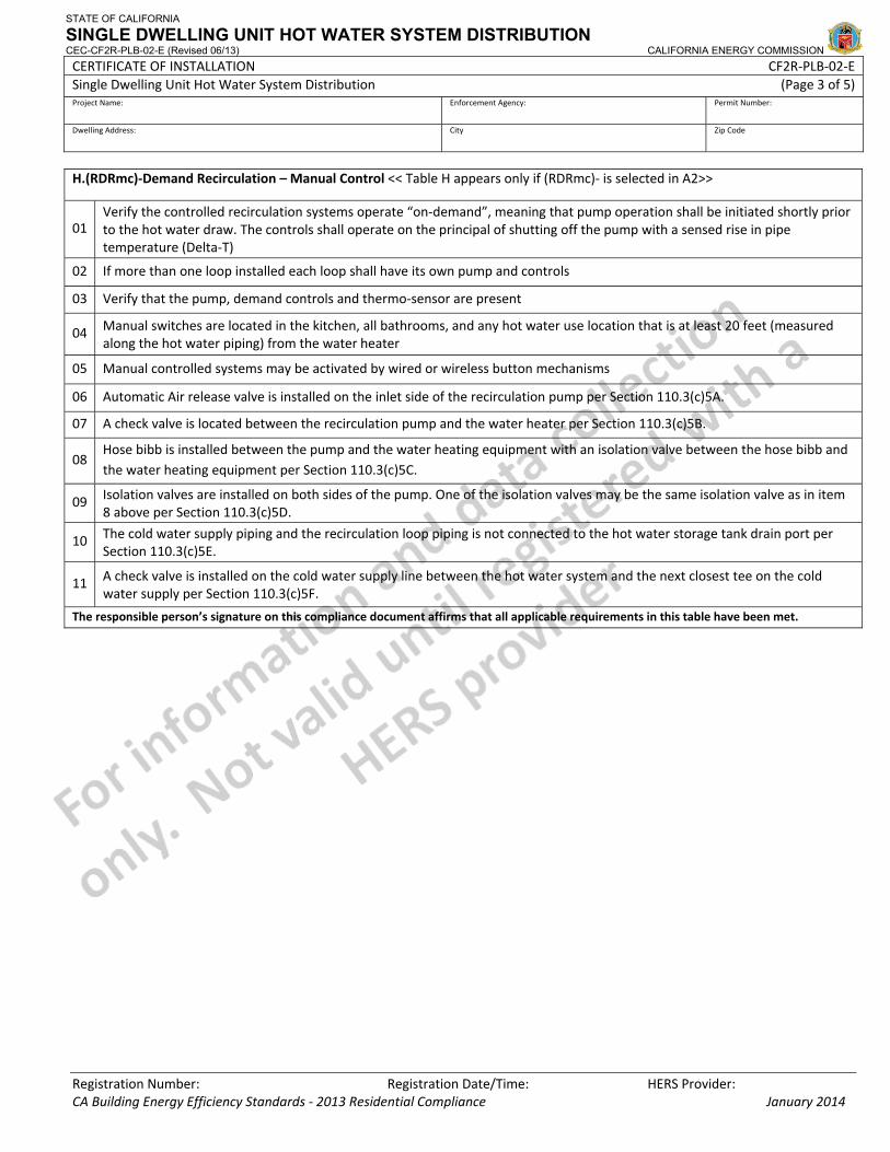
STATE OF CALIFORNIA
SINGLE DWELLING UNIT HOT WATER SYSTEM DISTRIBUTION CEC-CF2R-PLB-02-E (Revised 06/13) CALIFORNIA ENERGY COMMISSION CERTIFICATE OF INSTALLATION CF2R‐PLB‐02‐ESingle Dwelling Unit Hot Water System Distribution (Page 3 of 5)Project Name: Enforcement Agency: Permit Number:
Dwelling Address: City Zip Code
Registration Number: Registration Date/Time: HERS Provider: CA Building Energy Efficiency Standards ‐ 2013 Residential Compliance January 2014
H.(RDRmc)‐Demand Recirculation – Manual Control << Table H appears only if (RDRmc)‐ is selected in A2>>
01 Verify the controlled recirculation systems operate “on‐demand”, meaning that pump operation shall be initiated shortly prior to the hot water draw. The controls shall operate on the principal of shutting off the pump with a sensed rise in pipe temperature (Delta‐T)
02 If more than one loop installed each loop shall have its own pump and controls
03 Verify that the pump, demand controls and thermo‐sensor are present
04 Manual switches are located in the kitchen, all bathrooms, and any hot water use location that is at least 20 feet (measured along the hot water piping) from the water heater
05 Manual controlled systems may be activated by wired or wireless button mechanisms
06 Automatic Air release valve is installed on the inlet side of the recirculation pump per Section 110.3(c)5A.
07 A check valve is located between the recirculation pump and the water heater per Section 110.3(c)5B.
08 Hose bibb is installed between the pump and the water heating equipment with an isolation valve between the hose bibb and the water heating equipment per Section 110.3(c)5C.
09 Isolation valves are installed on both sides of the pump. One of the isolation valves may be the same isolation valve as in item 8 above per Section 110.3(c)5D.
10 The cold water supply piping and the recirculation loop piping is not connected to the hot water storage tank drain port per Section 110.3(c)5E.
11 A check valve is installed on the cold water supply line between the hot water system and the next closest tee on the cold water supply per Section 110.3(c)5F.
The responsible person’s signature on this compliance document affirms that all applicable requirements in this table have been met.
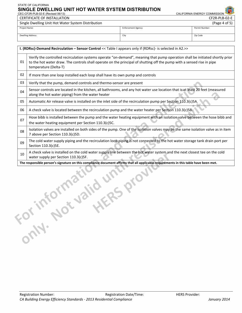
STATE OF CALIFORNIA
SINGLE DWELLING UNIT HOT WATER SYSTEM DISTRIBUTION CEC-CF2R-PLB-02-E (Revised 06/13) CALIFORNIA ENERGY COMMISSION CERTIFICATE OF INSTALLATION CF2R‐PLB‐02‐ESingle Dwelling Unit Hot Water System Distribution (Page 4 of 5)Project Name: Enforcement Agency: Permit Number:
Dwelling Address: City Zip Code
Registration Number: Registration Date/Time: HERS Provider: CA Building Energy Efficiency Standards ‐ 2013 Residential Compliance January 2014
I. (RDRsc)‐Demand Recirculation – Sensor Control << Table I appears only if (RDRsc)‐ is selected in A2.>>
01 Verify the controlled recirculation systems operate “on‐demand”, meaning that pump operation shall be initiated shortly prior to the hot water draw. The controls shall operate on the principal of shutting off the pump with a sensed rise in pipe temperature (Delta‐T)
02 If more than one loop installed each loop shall have its own pump and controls
03 Verify that the pump, demand controls and thermo‐sensor are present
04 Sensor controls are located in the kitchen, all bathrooms, and any hot water use location that is at least 20 feet (measured along the hot water piping) from the water heater
05 Automatic Air release valve is installed on the inlet side of the recirculation pump per Section 110.3(c)5A.
06 A check valve is located between the recirculation pump and the water heater per Section 110.3(c)5B.
07 Hose bibb is installed between the pump and the water heating equipment with an isolation valve between the hose bibb and the water heating equipment per Section 110.3(c)5C.
08 Isolation valves are installed on both sides of the pump. One of the isolation valves may be the same isolation valve as in item 7 above per Section 110.3(c)5D.
09 The cold water supply piping and the recirculation loop piping is not connected to the hot water storage tank drain port per Section 110.3(c)5E.
10 A check valve is installed on the cold water supply line between the hot water system and the next closest tee on the cold water supply per Section 110.3(c)5F.
The responsible person’s signature on this compliance document affirms that all applicable requirements in this table have been met.
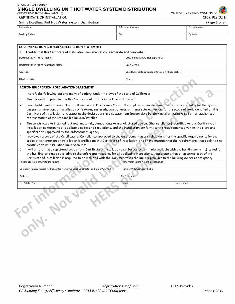
STATE OF CALIFORNIA
SINGLE DWELLING UNIT HOT WATER SYSTEM DISTRIBUTION CEC-CF2R-PLB-02-E (Revised 06/13) CALIFORNIA ENERGY COMMISSION CERTIFICATE OF INSTALLATION CF2R‐PLB‐02‐ESingle Dwelling Unit Hot Water System Distribution (Page 5 of 5)Project Name: Enforcement Agency: Permit Number:
Dwelling Address: City Zip Code
Registration Number: Registration Date/Time: HERS Provider: CA Building Energy Efficiency Standards ‐ 2013 Residential Compliance January 2014
DOCUMENTATION AUTHOR'S DECLARATION STATEMENT
1. I certify that this Certificate of Installation documentation is accurate and complete.
Documentation Author Name: Documentation Author Signature:
Documentation Author Company Name: Date Signed:
Address: CEA/HERS Certification Identification (If applicable):
City/State/Zip: Phone:
RESPONSIBLE PERSON'S DECLARATION STATEMENT
I certify the following under penalty of perjury, under the laws of the State of California:
1. The information provided on this Certificate of Installation is true and correct.
2. I am eligible under Division 3 of the Business and Professions Code in the applicable classification to accept responsibility for the system design, construction, or installation of features, materials, components, or manufactured devices for the scope of work identified on this Certificate of Installation, and attest to the declarations in this statement (responsible builder/installer), otherwise I am an authorized representative of the responsible builder/installer.
3. The constructed or installed features, materials, components or manufactured devices (the installation) identified on this Certificate of Installation conforms to all applicable codes and regulations, and the installation conforms to the requirements given on the plans and specifications approved by the enforcement agency.
4. I reviewed a copy of the Certificate of Compliance approved by the enforcement agency that identifies the specific requirements for the scope of construction or installation identified on this Certificate of Installation, and I have ensured that the requirements that apply to the construction or installation have been met.
5. I will ensure that a registered copy of this Certificate of Installation shall be posted, or made available with the building permit(s) issued for the building, and made available to the enforcement agency for all applicable inspections. I understand that a registered copy of this Certificate of Installation is required to be included with the documentation the builder provides to the building owner at occupancy.
Responsible Builder/Installer Name: Responsible Builder/Installer Signature:
Company Name: (Installing Subcontractor or General Contractor or Builder/Owner) Position With Company (Title):
Address: CSLB License:
City/State/Zip: Phone Date Signed:
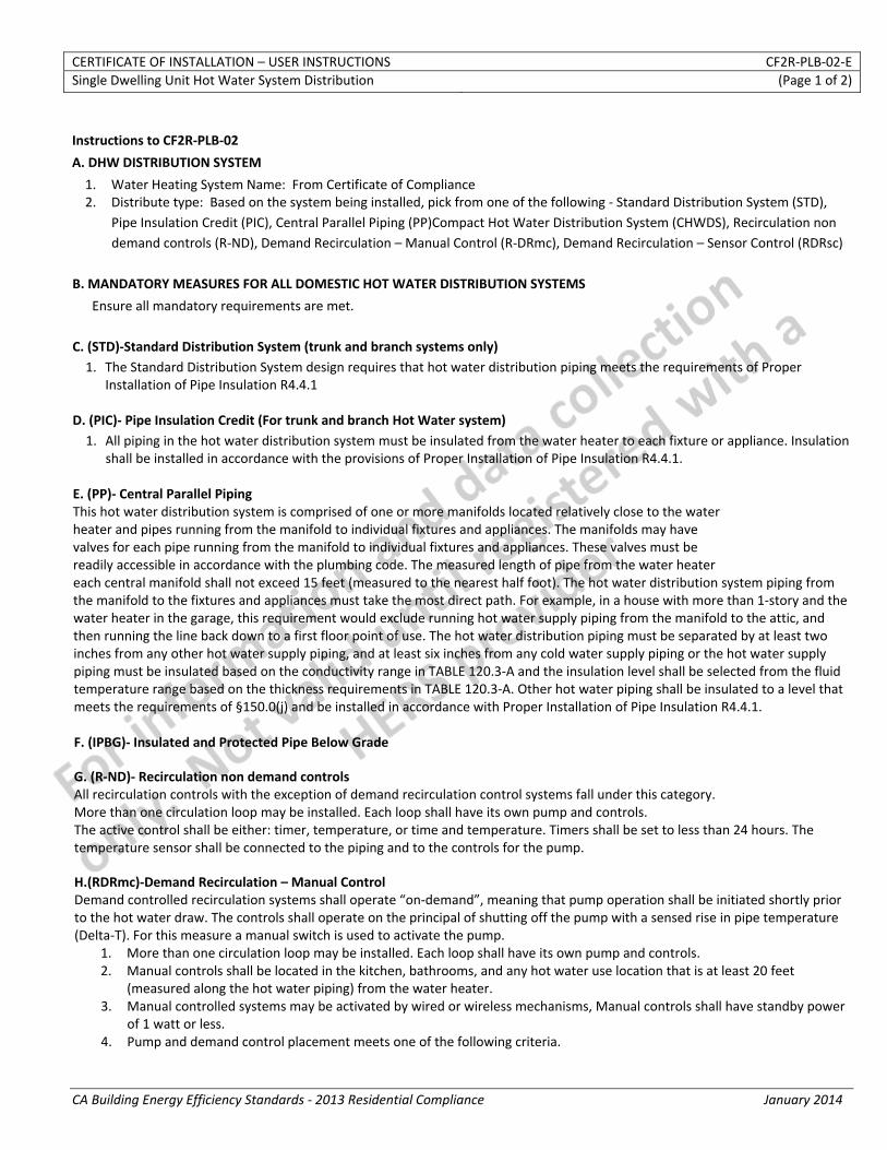
CERTIFICATE OF INSTALLATION – USER INSTRUCTIONS CF2R‐PLB‐02‐ESingle Dwelling Unit Hot Water System Distribution (Page 1 of 2)
CA Building Energy Efficiency Standards ‐ 2013 Residential Compliance January 2014
Instructions to CF2R‐PLB‐02
A. DHW DISTRIBUTION SYSTEM
1. Water Heating System Name: From Certificate of Compliance 2. Distribute type: Based on the system being installed, pick from one of the following ‐ Standard Distribution System (STD),
Pipe Insulation Credit (PIC), Central Parallel Piping (PP)Compact Hot Water Distribution System (CHWDS), Recirculation non demand controls (R‐ND), Demand Recirculation – Manual Control (R‐DRmc), Demand Recirculation – Sensor Control (RDRsc)
B. MANDATORY MEASURES FOR ALL DOMESTIC HOT WATER DISTRIBUTION SYSTEMS
Ensure all mandatory requirements are met. C. (STD)‐Standard Distribution System (trunk and branch systems only) 1. The Standard Distribution System design requires that hot water distribution piping meets the requirements of Proper
Installation of Pipe Insulation R4.4.1
D. (PIC)‐ Pipe Insulation Credit (For trunk and branch Hot Water system) 1. All piping in the hot water distribution system must be insulated from the water heater to each fixture or appliance. Insulation
shall be installed in accordance with the provisions of Proper Installation of Pipe Insulation R4.4.1. E. (PP)‐ Central Parallel Piping This hot water distribution system is comprised of one or more manifolds located relatively close to the water heater and pipes running from the manifold to individual fixtures and appliances. The manifolds may have valves for each pipe running from the manifold to individual fixtures and appliances. These valves must be readily accessible in accordance with the plumbing code. The measured length of pipe from the water heater each central manifold shall not exceed 15 feet (measured to the nearest half foot). The hot water distribution system piping from the manifold to the fixtures and appliances must take the most direct path. For example, in a house with more than 1‐story and the water heater in the garage, this requirement would exclude running hot water supply piping from the manifold to the attic, and then running the line back down to a first floor point of use. The hot water distribution piping must be separated by at least two inches from any other hot water supply piping, and at least six inches from any cold water supply piping or the hot water supply piping must be insulated based on the conductivity range in TABLE 120.3‐A and the insulation level shall be selected from the fluid temperature range based on the thickness requirements in TABLE 120.3‐A. Other hot water piping shall be insulated to a level that meets the requirements of §150.0(j) and be installed in accordance with Proper Installation of Pipe Insulation R4.4.1. F. (IPBG)‐ Insulated and Protected Pipe Below Grade G. (R‐ND)‐ Recirculation non demand controls All recirculation controls with the exception of demand recirculation control systems fall under this category. More than one circulation loop may be installed. Each loop shall have its own pump and controls. The active control shall be either: timer, temperature, or time and temperature. Timers shall be set to less than 24 hours. The temperature sensor shall be connected to the piping and to the controls for the pump. H.(RDRmc)‐Demand Recirculation – Manual Control Demand controlled recirculation systems shall operate “on‐demand”, meaning that pump operation shall be initiated shortly prior to the hot water draw. The controls shall operate on the principal of shutting off the pump with a sensed rise in pipe temperature (Delta‐T). For this measure a manual switch is used to activate the pump.
1. More than one circulation loop may be installed. Each loop shall have its own pump and controls. 2. Manual controls shall be located in the kitchen, bathrooms, and any hot water use location that is at least 20 feet
(measured along the hot water piping) from the water heater. 3. Manual controlled systems may be activated by wired or wireless mechanisms, Manual controls shall have standby power
of 1 watt or less. 4. Pump and demand control placement meets one of the following criteria.
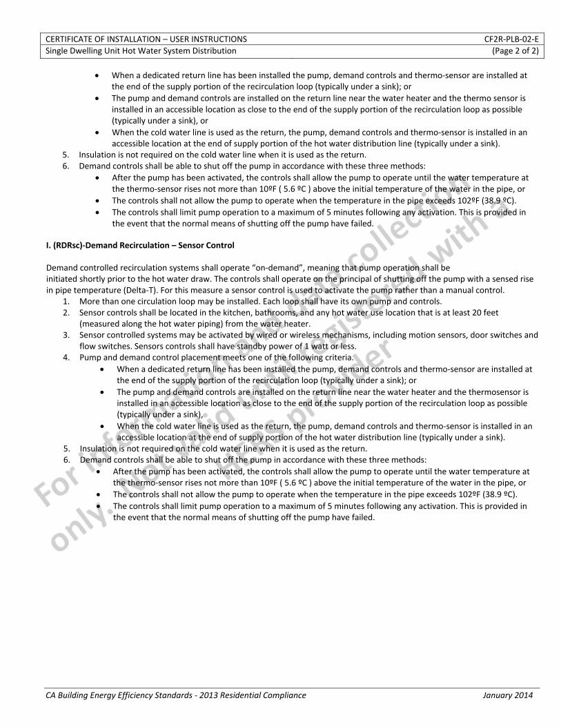
CERTIFICATE OF INSTALLATION – USER INSTRUCTIONS CF2R‐PLB‐02‐ESingle Dwelling Unit Hot Water System Distribution (Page 2 of 2)
CA Building Energy Efficiency Standards ‐ 2013 Residential Compliance January 2014
• When a dedicated return line has been installed the pump, demand controls and thermo‐sensor are installed at the end of the supply portion of the recirculation loop (typically under a sink); or
• The pump and demand controls are installed on the return line near the water heater and the thermo sensor is installed in an accessible location as close to the end of the supply portion of the recirculation loop as possible (typically under a sink), or
• When the cold water line is used as the return, the pump, demand controls and thermo‐sensor is installed in an accessible location at the end of supply portion of the hot water distribution line (typically under a sink).
5. Insulation is not required on the cold water line when it is used as the return. 6. Demand controls shall be able to shut off the pump in accordance with these three methods:
• After the pump has been activated, the controls shall allow the pump to operate until the water temperature at the thermo‐sensor rises not more than 10ºF ( 5.6 ºC ) above the initial temperature of the water in the pipe, or
• The controls shall not allow the pump to operate when the temperature in the pipe exceeds 102ºF (38.9 ºC). • The controls shall limit pump operation to a maximum of 5 minutes following any activation. This is provided in
the event that the normal means of shutting off the pump have failed. I. (RDRsc)‐Demand Recirculation – Sensor Control Demand controlled recirculation systems shall operate “on‐demand”, meaning that pump operation shall be initiated shortly prior to the hot water draw. The controls shall operate on the principal of shutting off the pump with a sensed rise in pipe temperature (Delta‐T). For this measure a sensor control is used to activate the pump rather than a manual control.
1. More than one circulation loop may be installed. Each loop shall have its own pump and controls. 2. Sensor controls shall be located in the kitchen, bathrooms, and any hot water use location that is at least 20 feet
(measured along the hot water piping) from the water heater. 3. Sensor controlled systems may be activated by wired or wireless mechanisms, including motion sensors, door switches and
flow switches. Sensors controls shall have standby power of 1 watt or less. 4. Pump and demand control placement meets one of the following criteria.
• When a dedicated return line has been installed the pump, demand controls and thermo‐sensor are installed at the end of the supply portion of the recirculation loop (typically under a sink); or
• The pump and demand controls are installed on the return line near the water heater and the thermosensor is installed in an accessible location as close to the end of the supply portion of the recirculation loop as possible (typically under a sink),
• When the cold water line is used as the return, the pump, demand controls and thermo‐sensor is installed in an accessible location at the end of supply portion of the hot water distribution line (typically under a sink).
5. Insulation is not required on the cold water line when it is used as the return. 6. Demand controls shall be able to shut off the pump in accordance with these three methods:
• After the pump has been activated, the controls shall allow the pump to operate until the water temperature at the thermo‐sensor rises not more than 10ºF ( 5.6 ºC ) above the initial temperature of the water in the pipe, or
• The controls shall not allow the pump to operate when the temperature in the pipe exceeds 102ºF (38.9 ºC). • The controls shall limit pump operation to a maximum of 5 minutes following any activation. This is provided in
the event that the normal means of shutting off the pump have failed.
CERTIFICATE OF INSTALLATION – DATA FIELD DEFINITIONS AND CALCULATIONS CF2R‐PLB‐02‐ESingle Dwelling Unit Hot Water System Distribution (Page 2 of 2)
CA Building Energy Efficiency Standards ‐ 2013 Residential Compliance January 2014
DOCUMENTATION AUTHOR'S DECLARATION STATEMENT
1. I certify that this Certificate of Installation documentation is accurate and complete.
Documentation Author Name: Documentation Author Signature:
Documentation Author Company Name: Date Signed:
Address: CEA/HERS Certification Identification (If applicable):
City/State/Zip: Phone:
RESPONSIBLE PERSON'S DECLARATION STATEMENT
I certify the following under penalty of perjury, under the laws of the State of California:
1. The information provided on this Certificate of Installation is true and correct.
2. I am eligible under Division 3 of the Business and Professions Code in the applicable classification to accept responsibility for the system design, construction, or installation of features, materials, components, or manufactured devices for the scope of work identified on this Certificate of Installation, and attest to the declarations in this statement (responsible builder/installer), otherwise I am an authorized representative of the responsible builder/installer.
3. The constructed or installed features, materials, components or manufactured devices (the installation) identified on this Certificate of Installation conforms to all applicable codes and regulations, and the installation conforms to the requirements given on the plans and specifications approved by the enforcement agency.
4. I reviewed a copy of the Certificate of Compliance approved by the enforcement agency that identifies the specific requirements for the scope of construction or installation identified on this Certificate of Installation, and I have ensured that the requirements that apply to the construction or installation have been met.
5. I will ensure that a registered copy of this Certificate of Installation shall be posted, or made available with the building permit(s) issued for the building, and made available to the enforcement agency for all applicable inspections. I understand that a registered copy of this Certificate of Installation is required to be included with the documentation the builder provides to the building owner at occupancy.
Responsible Builder/Installer Name: Responsible Builder/Installer Signature:
Company Name: (Installing Subcontractor or General Contractor or Builder/Owner) Position With Company (Title):
Address: CSLB License:
City/State/Zip: Phone Date Signed:
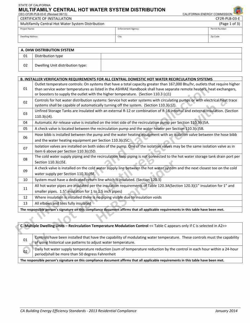
STATE OF CALIFORNIA
MULTIFAMILY CENTRAL HOT WATER SYSTEM DISTRIBUTION CEC-CF2R-PLB-03-E (Revised 06/13) CALIFORNIA ENERGY COMMISSION CERTIFICATE OF INSTALLATION CF2R‐PLB‐03‐EMultifamily Central Hot Water System Distribution (Page 1 of 3)Project Name: Enforcement Agency: Permit Number:
Dwelling Address: City Zip Code
CA Building Energy Efficiency Standards ‐ 2013 Residential Compliance January 2014
A. DHW DISTRIBUTION SYSTEM
01 Distribution type
02 Dwelling Unit distribution type:
B. INSTALLER VERIFICATION REQUIREMENTS FOR ALL CENTRAL DOMESTIC HOT WATER RECIRCULATION SYSTEMS
01 Outlet temperature controls: On systems that have a total capacity greater than 167,000 Btu/hr, outlets that require higher than service water temperatures as listed in the ASHRAE Handbook shall have separate remote heaters, heat exchangers, or boosters to supply the outlet with the higher temperature. (Section 110.3 (c)1)
02 Controls for hot water distribution systems: Service hot water systems with circulating pumps or with electrical heat trace systems shall be capable of automatically turning off the system. (Section 110.3(c)2).
03 Unfired Storage Tanks are insulated with an external R‐12 or combination of R‐16 internal and external Insulation. (Section 110.3(c)4).
04 Automatic Air release valve is installed on the inlet side of the recirculation pump per Section 110.3(c)5A.
05 A check valve is located between the recirculation pump and the water heater per Section 110.3(c)5B.
06 Hose bibb is installed between the pump and the water heating equipment with an isolation valve between the hose bibband the water heating equipment per Section 110.3(c)5C.
07 Isolation valves are installed on both sides of the pump. One of the isolation valves may be the same isolation valve as in item 6 above per Section 110.3(c)5D.
08 The cold water supply piping and the recirculation loop piping is not connected to the hot water storage tank drain port per Section 110.3(c)5E.
09 A check valve is installed on the cold water supply line between the hot water system and the next closest tee on the cold water supply per Section 110.3(c)5F.
10 System must have a dedicated return line which is insulated. (Section 120.3)
11 All hot water pipes are insulated per the insulation requirements of Table 120.3A(Section 120.3)(1” insulation for 1” and smaller pipes. 1.5” insulation for 1 to 1.5 inch pipes)
12 Where insulation is installed there is no piping visible due to insulation voids
13 All elbows and tees fully insulated
The responsible person’s signature on this compliance document affirms that all applicable requirements in this table have been met.
C. Multiple Dwelling Units – Recirculation Temperature Modulation Control << Table C appears only if C is selected in A2>>
01 Controls have been installed that have the capability of modulating water temperature. These controls must the capability of using historical use patterns to adjust water temperature.
02 Daily hot water supply temperature reduction (sum of temperature reduction by the control in each hour within a 24‐hour period)shall be more than 50 degress Fahrenheit
The responsible person’s signature on this compliance document affirms that all applicable requirements in this table have been met.
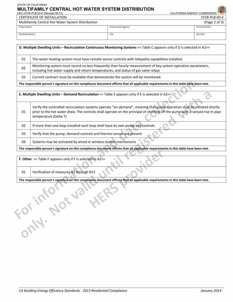
STATE OF CALIFORNIA
MULTIFAMILY CENTRAL HOT WATER SYSTEM DISTRIBUTION CEC-CF2R-PLB-03-E (Revised 06/13) CALIFORNIA ENERGY COMMISSION CERTIFICATE OF INSTALLATION CF2R‐PLB‐03‐EMultifamily Central Hot Water System Distribution (Page 2 of 3)Project Name: Enforcement Agency: Permit Number:
Dwelling Address: City Zip Code
CA Building Energy Efficiency Standards ‐ 2013 Residential Compliance January 2014
D. Multiple Dwelling Units – Recirculation Continuous Monitoring Systems << Table C appears only if D is selected in A2>>
01 The water heating system must have remote sensor controls with telepathy capabilities installed.
02 Monitoring system must record no less frequently than hourly measurement of key system operation parameters, including hot water supply and return temperatures, and status of gas valve relays
03 Current contract must be available that demonstrate the system will be monitored.
The responsible person’s signature on this compliance document affirms that all applicable requirements in this table have been met.
E. Multiple Dwelling Units – Demand Recirculation << Table E appears only if E is selected in A2>>
01 Verify the controlled recirculation systems operate “on‐demand”, meaning that pump operation shall be initiated shortly prior to the hot water draw. The controls shall operate on the principal of shutting off the pump with a sensed rise in pipe temperature (Delta‐T)
02 If more than one loop installed each loop shall have its own pump and controls
03 Verify that the pump, demand controls and thermo‐sensor are present
04 Systems may be activated by wired or wireless button mechanisms
The responsible person’s signature on this compliance document affirms that all applicable requirements in this table have been met.
F. Other << Table F appears only if F is selected in A2>>
01 Verification of measures B1 through B13
The responsible person’s signature on this compliance document affirms that all applicable requirements in this table have been met.
STATE OF CALIFORNIA
MULTIFAMILY CENTRAL HOT WATER SYSTEM DISTRIBUTION CEC-CF2R-PLB-03-E (Revised 06/13) CALIFORNIA ENERGY COMMISSION CERTIFICATE OF INSTALLATION CF2R‐PLB‐03‐EMultifamily Central Hot Water System Distribution (Page 3 of 3)Project Name: Enforcement Agency: Permit Number:
Dwelling Address: City Zip Code
CA Building Energy Efficiency Standards ‐ 2013 Residential Compliance January 2014
DOCUMENTATION AUTHOR'S DECLARATION STATEMENT
1. I certify that this Certificate of Installation documentation is accurate and complete.
Documentation Author Name: Documentation Author Signature:
Documentation Author Company Name: Date Signed:
Address: CEA/HERS Certification Identification (If applicable):
City/State/Zip: Phone:
RESPONSIBLE PERSON'S DECLARATION STATEMENT
I certify the following under penalty of perjury, under the laws of the State of California:
1. The information provided on this Certificate of Installation is true and correct.
2. I am eligible under Division 3 of the Business and Professions Code in the applicable classification to accept responsibility for the system design, construction, or installation of features, materials, components, or manufactured devices for the scope of work identified on this Certificate of Installation, and attest to the declarations in this statement (responsible builder/installer), otherwise I am an authorized representative of the responsible builder/installer.
3. The constructed or installed features, materials, components or manufactured devices (the installation) identified on this Certificate of Installation conforms to all applicable codes and regulations, and the installation conforms to the requirements given on the plans and specifications approved by the enforcement agency.
4. I reviewed a copy of the Certificate of Compliance approved by the enforcement agency that identifies the specific requirements for the scope of construction or installation identified on this Certificate of Installation, and I have ensured that the requirements that apply to the construction or installation have been met.
5. I will ensure that a registered copy of this Certificate of Installation shall be posted, or made available with the building permit(s) issued for the building, and made available to the enforcement agency for all applicable inspections. I understand that a registered copy of this Certificate of Installation is required to be included with the documentation the builder provides to the building owner at occupancy.
Responsible Builder/Installer Name: Responsible Builder/Installer Signature:
Company Name: (Installing Subcontractor or General Contractor or Builder/Owner) Position With Company (Title):
Address: CSLB License:
City/State/Zip: Phone Date Signed:
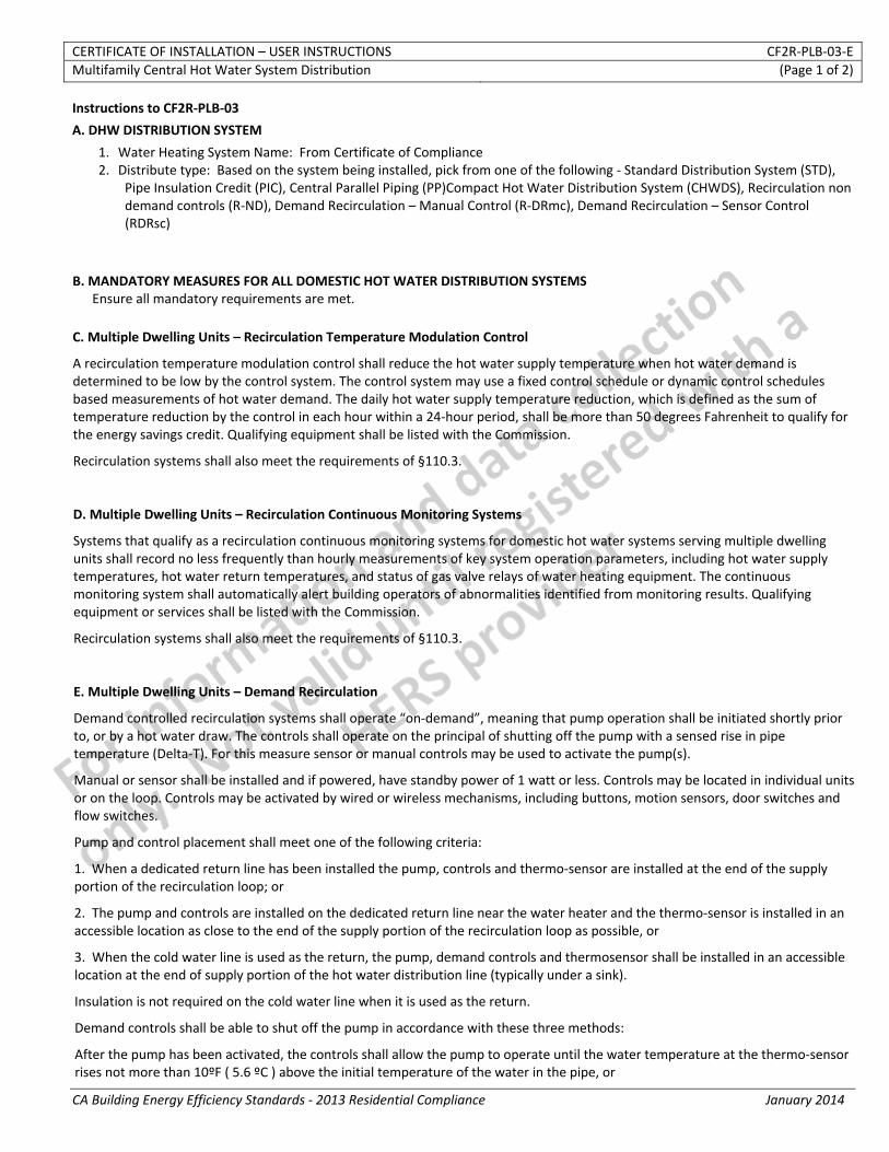
CERTIFICATE OF INSTALLATION – USER INSTRUCTIONS CF2R‐PLB‐03‐EMultifamily Central Hot Water System Distribution (Page 1 of 2)
CA Building Energy Efficiency Standards ‐ 2013 Residential Compliance January 2014
Instructions to CF2R‐PLB‐03
A. DHW DISTRIBUTION SYSTEM
1. Water Heating System Name: From Certificate of Compliance 2. Distribute type: Based on the system being installed, pick from one of the following ‐ Standard Distribution System (STD),
Pipe Insulation Credit (PIC), Central Parallel Piping (PP)Compact Hot Water Distribution System (CHWDS), Recirculation non demand controls (R‐ND), Demand Recirculation – Manual Control (R‐DRmc), Demand Recirculation – Sensor Control (RDRsc)
B. MANDATORY MEASURES FOR ALL DOMESTIC HOT WATER DISTRIBUTION SYSTEMS Ensure all mandatory requirements are met. C. Multiple Dwelling Units – Recirculation Temperature Modulation Control
A recirculation temperature modulation control shall reduce the hot water supply temperature when hot water demand is determined to be low by the control system. The control system may use a fixed control schedule or dynamic control schedules based measurements of hot water demand. The daily hot water supply temperature reduction, which is defined as the sum of temperature reduction by the control in each hour within a 24‐hour period, shall be more than 50 degrees Fahrenheit to qualify for the energy savings credit. Qualifying equipment shall be listed with the Commission.
Recirculation systems shall also meet the requirements of §110.3. D. Multiple Dwelling Units – Recirculation Continuous Monitoring Systems
Systems that qualify as a recirculation continuous monitoring systems for domestic hot water systems serving multiple dwelling units shall record no less frequently than hourly measurements of key system operation parameters, including hot water supply temperatures, hot water return temperatures, and status of gas valve relays of water heating equipment. The continuous monitoring system shall automatically alert building operators of abnormalities identified from monitoring results. Qualifying equipment or services shall be listed with the Commission.
Recirculation systems shall also meet the requirements of §110.3. E. Multiple Dwelling Units – Demand Recirculation
Demand controlled recirculation systems shall operate “on‐demand”, meaning that pump operation shall be initiated shortly prior to, or by a hot water draw. The controls shall operate on the principal of shutting off the pump with a sensed rise in pipe temperature (Delta‐T). For this measure sensor or manual controls may be used to activate the pump(s).
Manual or sensor shall be installed and if powered, have standby power of 1 watt or less. Controls may be located in individual units or on the loop. Controls may be activated by wired or wireless mechanisms, including buttons, motion sensors, door switches and flow switches.
Pump and control placement shall meet one of the following criteria:
1. When a dedicated return line has been installed the pump, controls and thermo‐sensor are installed at the end of the supply portion of the recirculation loop; or
2. The pump and controls are installed on the dedicated return line near the water heater and the thermo‐sensor is installed in an accessible location as close to the end of the supply portion of the recirculation loop as possible, or
3. When the cold water line is used as the return, the pump, demand controls and thermosensor shall be installed in an accessible location at the end of supply portion of the hot water distribution line (typically under a sink).
Insulation is not required on the cold water line when it is used as the return.
Demand controls shall be able to shut off the pump in accordance with these three methods:
After the pump has been activated, the controls shall allow the pump to operate until the water temperature at the thermo‐sensor rises not more than 10ºF ( 5.6 ºC ) above the initial temperature of the water in the pipe, or
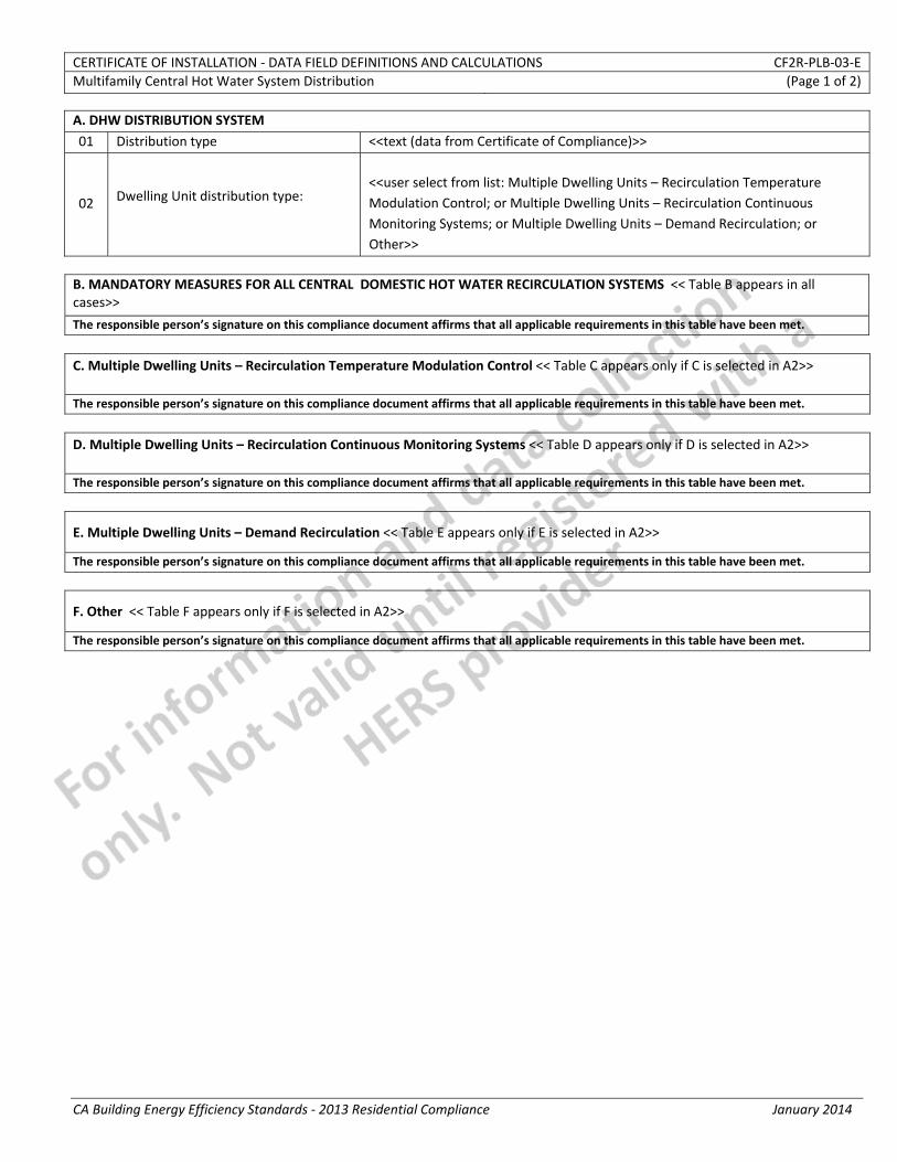
CERTIFICATE OF INSTALLATION ‐ DATA FIELD DEFINITIONS AND CALCULATIONS CF2R‐PLB‐03‐EMultifamily Central Hot Water System Distribution (Page 1 of 2)
CA Building Energy Efficiency Standards ‐ 2013 Residential Compliance January 2014
A. DHW DISTRIBUTION SYSTEM
01 Distribution type <<text (data from Certificate of Compliance)>>
02 Dwelling Unit distribution type: <<user select from list: Multiple Dwelling Units – Recirculation Temperature Modulation Control; or Multiple Dwelling Units – Recirculation Continuous Monitoring Systems; or Multiple Dwelling Units – Demand Recirculation; or Other>>
B. MANDATORY MEASURES FOR ALL CENTRAL DOMESTIC HOT WATER RECIRCULATION SYSTEMS << Table B appears in all cases>>
The responsible person’s signature on this compliance document affirms that all applicable requirements in this table have been met.
C. Multiple Dwelling Units – Recirculation Temperature Modulation Control << Table C appears only if C is selected in A2>> The responsible person’s signature on this compliance document affirms that all applicable requirements in this table have been met.
D. Multiple Dwelling Units – Recirculation Continuous Monitoring Systems << Table D appears only if D is selected in A2>> The responsible person’s signature on this compliance document affirms that all applicable requirements in this table have been met.
E. Multiple Dwelling Units – Demand Recirculation << Table E appears only if E is selected in A2>>
The responsible person’s signature on this compliance document affirms that all applicable requirements in this table have been met.
F. Other << Table F appears only if F is selected in A2>>
The responsible person’s signature on this compliance document affirms that all applicable requirements in this table have been met.
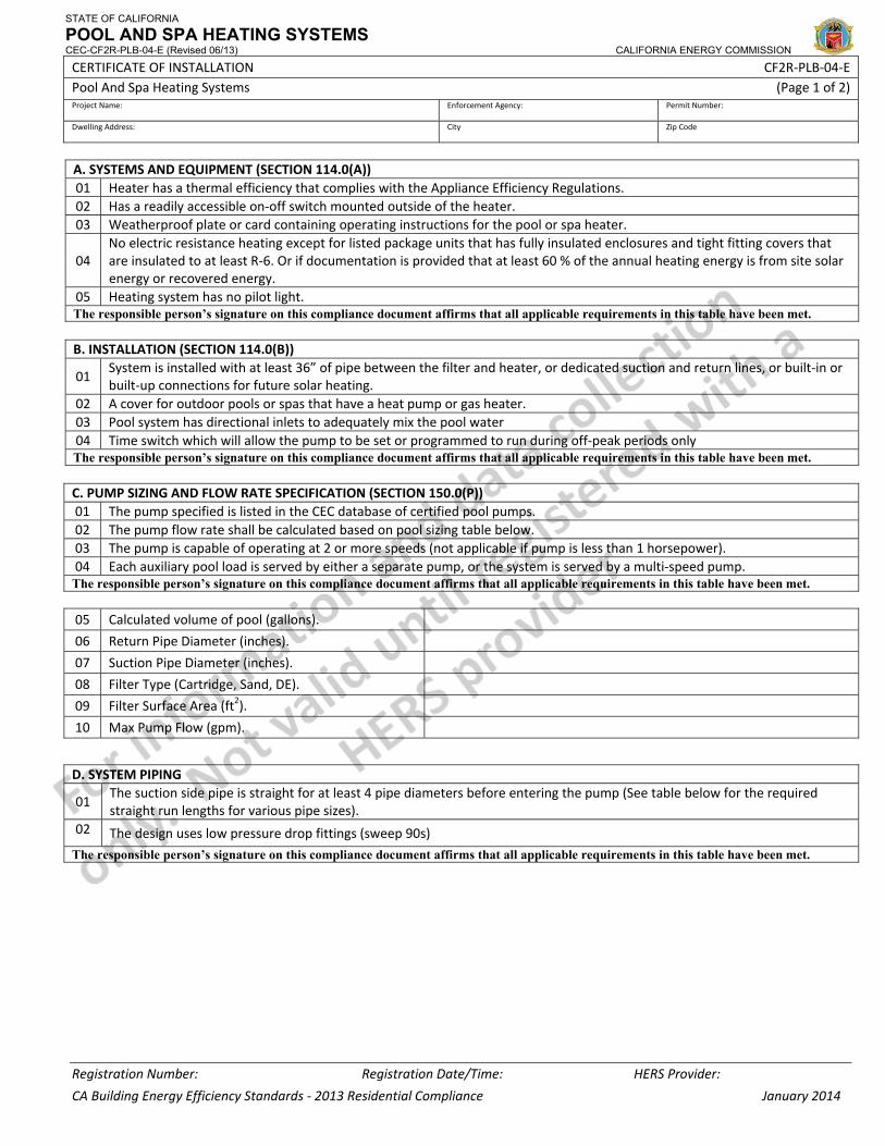
STATE OF CALIFORNIA
POOL AND SPA HEATING SYSTEMS CEC-CF2R-PLB-04-E (Revised 06/13) CALIFORNIA ENERGY COMMISSION
CERTIFICATE OF INSTALLATION CF2R‐PLB‐04‐E Pool And Spa Heating Systems (Page 1 of 2) Project Name: Enforcement Agency: Permit Number:
Dwelling Address: City Zip Code
Registration Number: Registration Date/Time: HERS Provider:
CA Building Energy Efficiency Standards ‐ 2013 Residential Compliance January 2014
A. SYSTEMS AND EQUIPMENT (SECTION 114.0(A))01 Heater has a thermal efficiency that complies with the Appliance Efficiency Regulations. 02 Has a readily accessible on‐off switch mounted outside of the heater. 03 Weatherproof plate or card containing operating instructions for the pool or spa heater.
04 No electric resistance heating except for listed package units that has fully insulated enclosures and tight fitting covers that are insulated to at least R‐6. Or if documentation is provided that at least 60 % of the annual heating energy is from site solar energy or recovered energy.
05 Heating system has no pilot light. The responsible person’s signature on this compliance document affirms that all applicable requirements in this table have been met. B. INSTALLATION (SECTION 114.0(B))
01 System is installed with at least 36” of pipe between the filter and heater, or dedicated suction and return lines, or built‐in or built‐up connections for future solar heating.
02 A cover for outdoor pools or spas that have a heat pump or gas heater.03 Pool system has directional inlets to adequately mix the pool water 04 Time switch which will allow the pump to be set or programmed to run during off‐peak periods only The responsible person’s signature on this compliance document affirms that all applicable requirements in this table have been met.
C. PUMP SIZING AND FLOW RATE SPECIFICATION (SECTION 150.0(P))01 The pump specified is listed in the CEC database of certified pool pumps.02 The pump flow rate shall be calculated based on pool sizing table below.03 The pump is capable of operating at 2 or more speeds (not applicable if pump is less than 1 horsepower).04 Each auxiliary pool load is served by either a separate pump, or the system is served by a multi‐speed pump.The responsible person’s signature on this compliance document affirms that all applicable requirements in this table have been met. 05 Calculated volume of pool (gallons).
06 Return Pipe Diameter (inches).
07 Suction Pipe Diameter (inches).
08 Filter Type (Cartridge, Sand, DE).
09 Filter Surface Area (ft2).
10 Max Pump Flow (gpm).
D. SYSTEM PIPING
01 The suction side pipe is straight for at least 4 pipe diameters before entering the pump (See table below for the required straight run lengths for various pipe sizes).
02 The design uses low pressure drop fittings (sweep 90s)
The responsible person’s signature on this compliance document affirms that all applicable requirements in this table have been met.
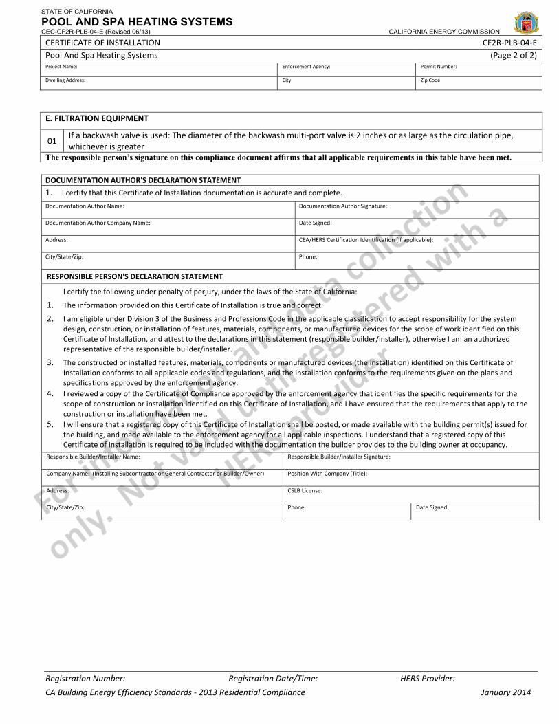
STATE OF CALIFORNIA
POOL AND SPA HEATING SYSTEMS CEC-CF2R-PLB-04-E (Revised 06/13) CALIFORNIA ENERGY COMMISSION
CERTIFICATE OF INSTALLATION CF2R‐PLB‐04‐E Pool And Spa Heating Systems (Page 2 of 2) Project Name: Enforcement Agency: Permit Number:
Dwelling Address: City Zip Code
Registration Number: Registration Date/Time: HERS Provider:
CA Building Energy Efficiency Standards ‐ 2013 Residential Compliance January 2014
E. FILTRATION EQUIPMENT
01 If a backwash valve is used: The diameter of the backwash multi‐port valve is 2 inches or as large as the circulation pipe, whichever is greater
The responsible person’s signature on this compliance document affirms that all applicable requirements in this table have been met.
DOCUMENTATION AUTHOR'S DECLARATION STATEMENT
1. I certify that this Certificate of Installation documentation is accurate and complete.
Documentation Author Name: Documentation Author Signature:
Documentation Author Company Name: Date Signed:
Address: CEA/HERS Certification Identification (If applicable):
City/State/Zip: Phone:
RESPONSIBLE PERSON'S DECLARATION STATEMENT
I certify the following under penalty of perjury, under the laws of the State of California:
1. The information provided on this Certificate of Installation is true and correct.
2. I am eligible under Division 3 of the Business and Professions Code in the applicable classification to accept responsibility for the system design, construction, or installation of features, materials, components, or manufactured devices for the scope of work identified on this Certificate of Installation, and attest to the declarations in this statement (responsible builder/installer), otherwise I am an authorized representative of the responsible builder/installer.
3. The constructed or installed features, materials, components or manufactured devices (the installation) identified on this Certificate of Installation conforms to all applicable codes and regulations, and the installation conforms to the requirements given on the plans and specifications approved by the enforcement agency.
4. I reviewed a copy of the Certificate of Compliance approved by the enforcement agency that identifies the specific requirements for the scope of construction or installation identified on this Certificate of Installation, and I have ensured that the requirements that apply to the construction or installation have been met.
5. I will ensure that a registered copy of this Certificate of Installation shall be posted, or made available with the building permit(s) issued for the building, and made available to the enforcement agency for all applicable inspections. I understand that a registered copy of this Certificate of Installation is required to be included with the documentation the builder provides to the building owner at occupancy.
Responsible Builder/Installer Name: Responsible Builder/Installer Signature:
Company Name: (Installing Subcontractor or General Contractor or Builder/Owner) Position With Company (Title):
Address: CSLB License:
City/State/Zip: Phone Date Signed:
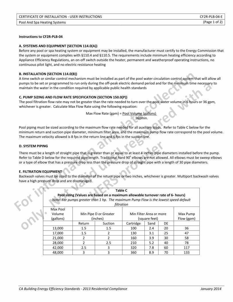
CERTIFICATE OF INSTALLATION ‐ USER INSTRUCTIONS CF2R‐PLB‐04‐E
Pool And Spa Heating Systems (Page 1 of 2)
CA Building Energy Efficiency Standards ‐ 2013 Residential Compliance January 2014
Instructions to CF2R‐PLB‐04 A. SYSTEMS AND EQUIPMENT (SECTION 114.0(A)) Before any pool or spa heating system or equipment may be installed, the manufacturer must certify to the Energy Commission that the system or equipment complies with §110.4 and §110.5. The requirements include minimum heating efficiency according to Appliance Efficiency Regulations, an on‐off switch outside the heater, permanent and weatherproof operating instructions, no continuous pilot light, and no electric resistance heating B. INSTALLATION (SECTION 114.0(B)) A time switch or similar control mechanism must be installed as part of the pool water circulation control system that will allow all pumps to be set or programmed to run only during the off‐peak electric demand period and for the minimum time necessary to maintain the water in the condition required by applicable public health standards C. PUMP SIZING AND FLOW RATE SPECIFICATION (SECTION 150.0(P)) The pool filtration flow rate may not be greater than the rate needed to turn over the pool water volume in 6 hours or 36 gpm, whichever is greater. Calculate Max Flow Rate using the following equation:
Max Flow Rate (gpm) = Pool Volume (gallons) 360min.
Pool piping must be sized according to the maximum flow rate needed for all auxiliary loads. Refer to Table C below for the minimum return and suction pipe diameter, minimum filter area, and the maximum pump flow rate correspond to the pool volume. The maximum velocity allowed is 8 fps in the return line and 6 fps in the suction line. D. SYSTEM PIPING
There must be a length of straight pipe that is greater than or equal to at least 4 inches pipe diameters installed before the pump. Refer to Table D below for the required pipe length. Traditional hard 90o elbows are not allowed. All elbows must be sweep elbows or a type of elbow that has a pressure drop less than the pressure drop of straight pipe with a length of 30 pipe diameters. E. FILTRATION EQUIPMENT Backwash valves must be sized to the diameter of the return pipe or two inches, whichever is greater. Multiport backwash valves have a high pressure drop and are discouraged.
Table CPool sizing (Values are based on a maximum allowable turnover rate of 6‐ hours)
Note: For pumps greater than 1 hp. The maximum Pump Flow is the lowest speed default filtration
Max Pool Volume (gallons)
Min Pipe D or Greater (inches)
Min Filter Area or more (square feet)
Max Pump Flow (gpm)
Return Suction Cartridge Sand DE 13,000 1.5 1.5 100 2.4 20 3617,000 1.5 2 130 3.1 25 4721,000 2 2 160 3.9 30 5828,000 2 2.5 210 5.2 40 7842,000 2.5 3 320 7.8 60 11748,000 3 3 360 8.9 70 133
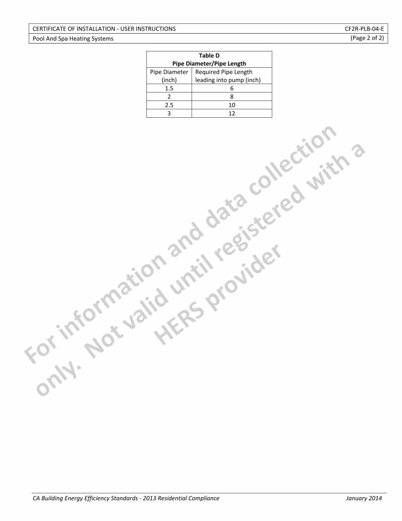
CERTIFICATE OF INSTALLATION ‐ USER INSTRUCTIONS CF2R‐PLB‐04‐E
Pool And Spa Heating Systems (Page 2 of 2)
CA Building Energy Efficiency Standards ‐ 2013 Residential Compliance January 2014
Table D Pipe Diameter/Pipe Length
Pipe Diameter(inch)
Required Pipe Length leading into pump (inch)
1.5 62 82.5 103 12
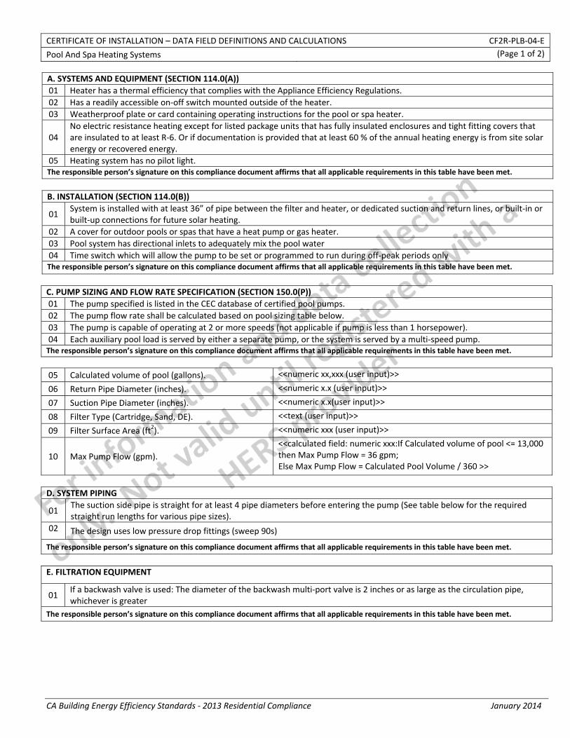
CERTIFICATE OF INSTALLATION – DATA FIELD DEFINITIONS AND CALCULATIONS CF2R‐PLB‐04‐E
Pool And Spa Heating Systems (Page 1 of 2)
CA Building Energy Efficiency Standards ‐ 2013 Residential Compliance January 2014
A. SYSTEMS AND EQUIPMENT (SECTION 114.0(A))01 Heater has a thermal efficiency that complies with the Appliance Efficiency Regulations. 02 Has a readily accessible on‐off switch mounted outside of the heater. 03 Weatherproof plate or card containing operating instructions for the pool or spa heater.
04 No electric resistance heating except for listed package units that has fully insulated enclosures and tight fitting covers that are insulated to at least R‐6. Or if documentation is provided that at least 60 % of the annual heating energy is from site solar energy or recovered energy.
05 Heating system has no pilot light. The responsible person’s signature on this compliance document affirms that all applicable requirements in this table have been met.
B. INSTALLATION (SECTION 114.0(B))
01 System is installed with at least 36” of pipe between the filter and heater, or dedicated suction and return lines, or built‐in or built‐up connections for future solar heating.
02 A cover for outdoor pools or spas that have a heat pump or gas heater.03 Pool system has directional inlets to adequately mix the pool water 04 Time switch which will allow the pump to be set or programmed to run during off‐peak periods only The responsible person’s signature on this compliance document affirms that all applicable requirements in this table have been met.
C. PUMP SIZING AND FLOW RATE SPECIFICATION (SECTION 150.0(P))01 The pump specified is listed in the CEC database of certified pool pumps.02 The pump flow rate shall be calculated based on pool sizing table below.03 The pump is capable of operating at 2 or more speeds (not applicable if pump is less than 1 horsepower).04 Each auxiliary pool load is served by either a separate pump, or the system is served by a multi‐speed pump.The responsible person’s signature on this compliance document affirms that all applicable requirements in this table have been met.
05 Calculated volume of pool (gallons). <<numeric xx,xxx (user input)>>
06 Return Pipe Diameter (inches). <<numeric x.x (user input)>>
07 Suction Pipe Diameter (inches). <<numeric x.x(user input)>>
08 Filter Type (Cartridge, Sand, DE). <<text (user input)>>
09 Filter Surface Area (ft2). <<numeric xxx (user input)>>
10 Max Pump Flow (gpm). <<calculated field: numeric xxx:If Calculated volume of pool <= 13,000 then Max Pump Flow = 36 gpm; Else Max Pump Flow = Calculated Pool Volume / 360 >>
D. SYSTEM PIPING
01 The suction side pipe is straight for at least 4 pipe diameters before entering the pump (See table below for the required straight run lengths for various pipe sizes).
02 The design uses low pressure drop fittings (sweep 90s)
The responsible person’s signature on this compliance document affirms that all applicable requirements in this table have been met.
E. FILTRATION EQUIPMENT
01 If a backwash valve is used: The diameter of the backwash multi‐port valve is 2 inches or as large as the circulation pipe, whichever is greater
The responsible person’s signature on this compliance document affirms that all applicable requirements in this table have been met.
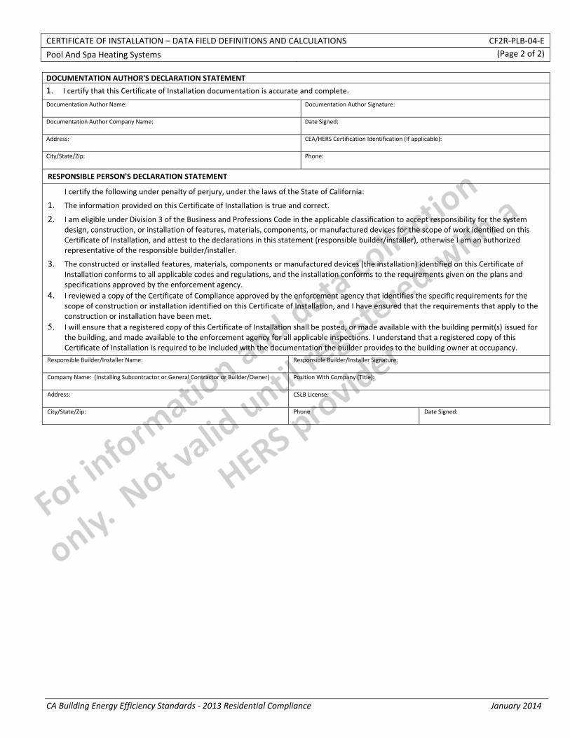
CERTIFICATE OF INSTALLATION – DATA FIELD DEFINITIONS AND CALCULATIONS CF2R‐PLB‐04‐E
Pool And Spa Heating Systems (Page 2 of 2)
CA Building Energy Efficiency Standards ‐ 2013 Residential Compliance January 2014
DOCUMENTATION AUTHOR'S DECLARATION STATEMENT
1. I certify that this Certificate of Installation documentation is accurate and complete.
Documentation Author Name: Documentation Author Signature:
Documentation Author Company Name: Date Signed:
Address: CEA/HERS Certification Identification (If applicable):
City/State/Zip: Phone:
RESPONSIBLE PERSON'S DECLARATION STATEMENT
I certify the following under penalty of perjury, under the laws of the State of California:
1. The information provided on this Certificate of Installation is true and correct.
2. I am eligible under Division 3 of the Business and Professions Code in the applicable classification to accept responsibility for the system design, construction, or installation of features, materials, components, or manufactured devices for the scope of work identified on this Certificate of Installation, and attest to the declarations in this statement (responsible builder/installer), otherwise I am an authorized representative of the responsible builder/installer.
3. The constructed or installed features, materials, components or manufactured devices (the installation) identified on this Certificate of Installation conforms to all applicable codes and regulations, and the installation conforms to the requirements given on the plans and specifications approved by the enforcement agency.
4. I reviewed a copy of the Certificate of Compliance approved by the enforcement agency that identifies the specific requirements for the scope of construction or installation identified on this Certificate of Installation, and I have ensured that the requirements that apply to the construction or installation have been met.
5. I will ensure that a registered copy of this Certificate of Installation shall be posted, or made available with the building permit(s) issued for the building, and made available to the enforcement agency for all applicable inspections. I understand that a registered copy of this Certificate of Installation is required to be included with the documentation the builder provides to the building owner at occupancy.
Responsible Builder/Installer Name: Responsible Builder/Installer Signature:
Company Name: (Installing Subcontractor or General Contractor or Builder/Owner) Position With Company (Title):
Address: CSLB License:
City/State/Zip: Phone Date Signed:
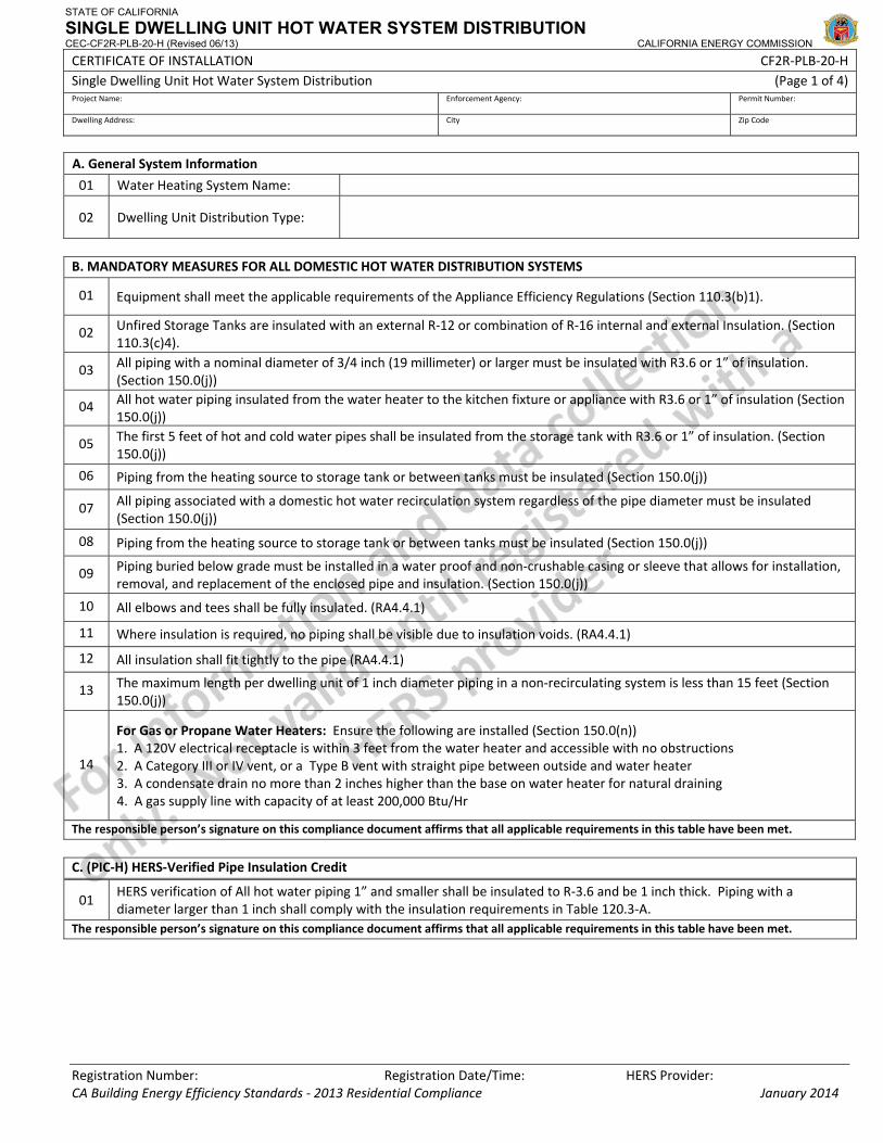
STATE OF CALIFORNIA
SINGLE DWELLING UNIT HOT WATER SYSTEM DISTRIBUTION CEC-CF2R-PLB-20-H (Revised 06/13) CALIFORNIA ENERGY COMMISSION
CERTIFICATE OF INSTALLATION CF2R‐PLB‐20‐H Single Dwelling Unit Hot Water System Distribution (Page 1 of 4) Project Name: Enforcement Agency: Permit Number:
Dwelling Address: City Zip Code
Registration Number: Registration Date/Time: HERS Provider: CA Building Energy Efficiency Standards ‐ 2013 Residential Compliance January 2014
A. General System Information
01 Water Heating System Name:
02 Dwelling Unit Distribution Type:
B. MANDATORY MEASURES FOR ALL DOMESTIC HOT WATER DISTRIBUTION SYSTEMS
01 Equipment shall meet the applicable requirements of the Appliance Efficiency Regulations (Section 110.3(b)1).
02 Unfired Storage Tanks are insulated with an external R‐12 or combination of R‐16 internal and external Insulation. (Section 110.3(c)4).
03 All piping with a nominal diameter of 3/4 inch (19 millimeter) or larger must be insulated with R3.6 or 1” of insulation. (Section 150.0(j))
04 All hot water piping insulated from the water heater to the kitchen fixture or appliance with R3.6 or 1” of insulation (Section 150.0(j))
05 The first 5 feet of hot and cold water pipes shall be insulated from the storage tank with R3.6 or 1” of insulation. (Section 150.0(j))
06 Piping from the heating source to storage tank or between tanks must be insulated (Section 150.0(j))
07 All piping associated with a domestic hot water recirculation system regardless of the pipe diameter must be insulated (Section 150.0(j))
08 Piping from the heating source to storage tank or between tanks must be insulated (Section 150.0(j))
09 Piping buried below grade must be installed in a water proof and non‐crushable casing or sleeve that allows for installation, removal, and replacement of the enclosed pipe and insulation. (Section 150.0(j))
10 All elbows and tees shall be fully insulated. (RA4.4.1)
11 Where insulation is required, no piping shall be visible due to insulation voids. (RA4.4.1)
12 All insulation shall fit tightly to the pipe (RA4.4.1)
13 The maximum length per dwelling unit of 1 inch diameter piping in a non‐recirculating system is less than 15 feet (Section 150.0(j))
14
For Gas or Propane Water Heaters: Ensure the following are installed (Section 150.0(n)) 1. A 120V electrical receptacle is within 3 feet from the water heater and accessible with no obstructions 2. A Category III or IV vent, or a Type B vent with straight pipe between outside and water heater 3. A condensate drain no more than 2 inches higher than the base on water heater for natural draining 4. A gas supply line with capacity of at least 200,000 Btu/Hr
The responsible person’s signature on this compliance document affirms that all applicable requirements in this table have been met.
C. (PIC‐H) HERS‐Verified Pipe Insulation Credit
01 HERS verification of All hot water piping 1” and smaller shall be insulated to R‐3.6 and be 1 inch thick. Piping with a diameter larger than 1 inch shall comply with the insulation requirements in Table 120.3‐A.
The responsible person’s signature on this compliance document affirms that all applicable requirements in this table have been met.
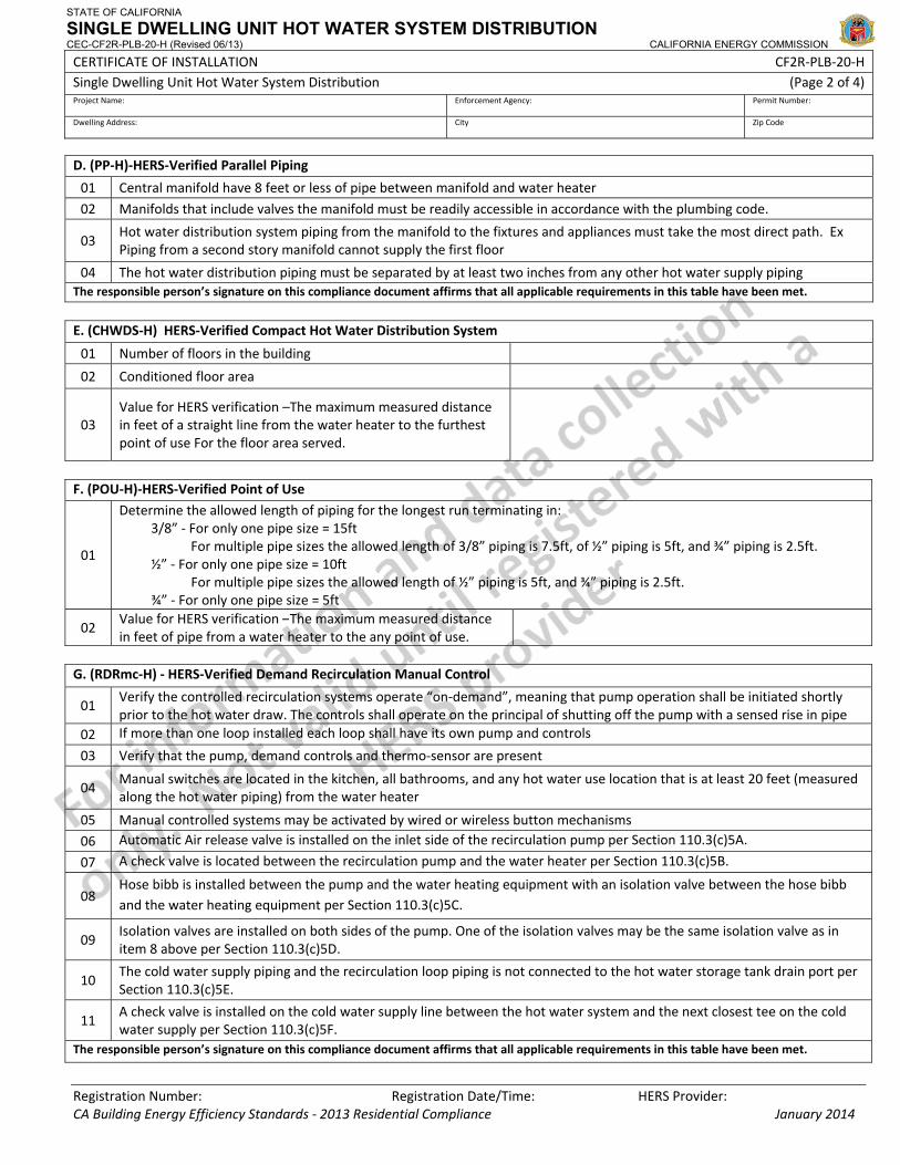
STATE OF CALIFORNIA
SINGLE DWELLING UNIT HOT WATER SYSTEM DISTRIBUTION CEC-CF2R-PLB-20-H (Revised 06/13) CALIFORNIA ENERGY COMMISSION
CERTIFICATE OF INSTALLATION CF2R‐PLB‐20‐H Single Dwelling Unit Hot Water System Distribution (Page 2 of 4) Project Name: Enforcement Agency: Permit Number:
Dwelling Address: City Zip Code
Registration Number: Registration Date/Time: HERS Provider: CA Building Energy Efficiency Standards ‐ 2013 Residential Compliance January 2014
D. (PP‐H)‐HERS‐Verified Parallel Piping
01 Central manifold have 8 feet or less of pipe between manifold and water heater
02 Manifolds that include valves the manifold must be readily accessible in accordance with the plumbing code.
03 Hot water distribution system piping from the manifold to the fixtures and appliances must take the most direct path. Ex Piping from a second story manifold cannot supply the first floor
04 The hot water distribution piping must be separated by at least two inches from any other hot water supply piping The responsible person’s signature on this compliance document affirms that all applicable requirements in this table have been met.
E. (CHWDS‐H) HERS‐Verified Compact Hot Water Distribution System
01 Number of floors in the building
02 Conditioned floor area
03 Value for HERS verification –The maximum measured distance in feet of a straight line from the water heater to the furthest point of use For the floor area served.
F. (POU‐H)‐HERS‐Verified Point of Use
01
Determine the allowed length of piping for the longest run terminating in:3/8” ‐ For only one pipe size = 15ft
For multiple pipe sizes the allowed length of 3/8” piping is 7.5ft, of ½” piping is 5ft, and ¾” piping is 2.5ft. ½” ‐ For only one pipe size = 10ft
For multiple pipe sizes the allowed length of ½” piping is 5ft, and ¾” piping is 2.5ft. ¾” ‐ For only one pipe size = 5ft
02 Value for HERS verification –The maximum measured distance in feet of pipe from a water heater to the any point of use.
G. (RDRmc‐H) ‐ HERS‐Verified Demand Recirculation Manual Control
01 Verify the controlled recirculation systems operate “on‐demand”, meaning that pump operation shall be initiated shortly prior to the hot water draw. The controls shall operate on the principal of shutting off the pump with a sensed rise in pipe
02 If more than one loop installed each loop shall have its own pump and controls
03 Verify that the pump, demand controls and thermo‐sensor are present
04 Manual switches are located in the kitchen, all bathrooms, and any hot water use location that is at least 20 feet (measured along the hot water piping) from the water heater
05 Manual controlled systems may be activated by wired or wireless button mechanisms
06 Automatic Air release valve is installed on the inlet side of the recirculation pump per Section 110.3(c)5A.
07 A check valve is located between the recirculation pump and the water heater per Section 110.3(c)5B.
08 Hose bibb is installed between the pump and the water heating equipment with an isolation valve between the hose bibb and the water heating equipment per Section 110.3(c)5C.
09 Isolation valves are installed on both sides of the pump. One of the isolation valves may be the same isolation valve as in item 8 above per Section 110.3(c)5D.
10 The cold water supply piping and the recirculation loop piping is not connected to the hot water storage tank drain port per Section 110.3(c)5E.
11 A check valve is installed on the cold water supply line between the hot water system and the next closest tee on the cold water supply per Section 110.3(c)5F.
The responsible person’s signature on this compliance document affirms that all applicable requirements in this table have been met.

STATE OF CALIFORNIA
SINGLE DWELLING UNIT HOT WATER SYSTEM DISTRIBUTION CEC-CF2R-PLB-20-H (Revised 06/13) CALIFORNIA ENERGY COMMISSION
CERTIFICATE OF INSTALLATION CF2R‐PLB‐20‐H Single Dwelling Unit Hot Water System Distribution (Page 3 of 4) Project Name: Enforcement Agency: Permit Number:
Dwelling Address: City Zip Code
Registration Number: Registration Date/Time: HERS Provider: CA Building Energy Efficiency Standards ‐ 2013 Residential Compliance January 2014
H.(RDRsc‐H) HERS‐Verified Demand Recirculation Sensor Control<< Table H appears only if (RDRsc‐H)‐ is selected in A2.>>
01 Verify the controlled recirculation systems operate “on‐demand”, meaning that pump operation shall be initiated shortly prior to the hot water draw. The controls shall operate on the principal of shutting off the pump with a sensed rise in pipe
02 If more than one loop installed each loop shall have its own pump and controls
03 Verify that the pump, demand controls and thermo‐sensor are present
04 Sensor controls are located in the kitchen, all bathrooms, and any hot water use location that is at least 20 feet (measured
05 Sensor controlled systems may be activated by wired or wireless button mechanisms
06 Automatic Air release valve is installed on the inlet side of the recirculation pump per Section 110.3(c)5A.
07 A check valve is located between the recirculation pump and the water heater per Section 110.3(c)5B.
08 Hose bibb is installed between the pump and the water heating equipment with an isolation valve between the hose bibb and the water heating equipment per Section 110.3(c)5C.
09 Isolation valves are installed on both sides of the pump. One of the isolation valves may be the same isolation valve as in item 8 above per Section 110.3(c)5D.
10 The cold water supply piping and the recirculation loop piping is not connected to the hot water storage tank drain port per Section 110.3(c)5E.
11 A check valve is installed on the cold water supply line between the hot water system and the next closest tee on the cold water supply per Section 110.3(c)5F.
The responsible person’s signature on this compliance document affirms that all applicable requirements in this table have been met.
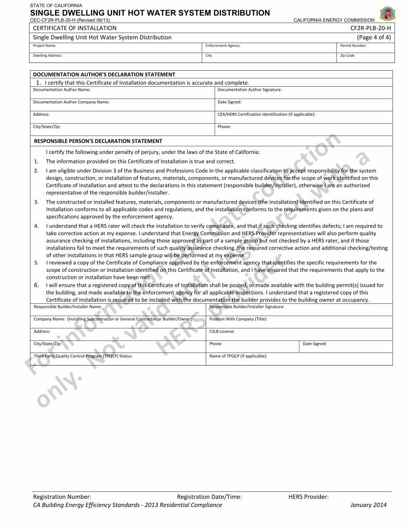
STATE OF CALIFORNIA
SINGLE DWELLING UNIT HOT WATER SYSTEM DISTRIBUTION CEC-CF2R-PLB-20-H (Revised 06/13) CALIFORNIA ENERGY COMMISSION
CERTIFICATE OF INSTALLATION CF2R‐PLB‐20‐H Single Dwelling Unit Hot Water System Distribution (Page 4 of 4) Project Name: Enforcement Agency: Permit Number:
Dwelling Address: City Zip Code
Registration Number: Registration Date/Time: HERS Provider: CA Building Energy Efficiency Standards ‐ 2013 Residential Compliance January 2014
DOCUMENTATION AUTHOR'S DECLARATION STATEMENT1. I certify that this Certificate of Installation documentation is accurate and complete.
Documentation Author Name: Documentation Author Signature:
Documentation Author Company Name: Date Signed:
Address: CEA/HERS Certification Identification (If applicable):
City/State/Zip: Phone:
RESPONSIBLE PERSON'S DECLARATION STATEMENT
I certify the following under penalty of perjury, under the laws of the State of California:
1. The information provided on this Certificate of Installation is true and correct.
2. I am eligible under Division 3 of the Business and Professions Code in the applicable classification to accept responsibility for the system design, construction, or installation of features, materials, components, or manufactured devices for the scope of work identified on this Certificate of Installation and attest to the declarations in this statement (responsible builder/installer), otherwise I am an authorized representative of the responsible builder/installer.
3. The constructed or installed features, materials, components or manufactured devices (the installation) identified on this Certificate of Installation conforms to all applicable codes and regulations, and the installation conforms to the requirements given on the plans and specifications approved by the enforcement agency.
4. I understand that a HERS rater will check the installation to verify compliance, and that if such checking identifies defects; I am required to take corrective action at my expense. I understand that Energy Commission and HERS Provider representatives will also perform quality assurance checking of installations, including those approved as part of a sample group but not checked by a HERS rater, and if those installations fail to meet the requirements of such quality assurance checking, the required corrective action and additional checking/testing of other installations in that HERS sample group will be performed at my expense.
5. I reviewed a copy of the Certificate of Compliance approved by the enforcement agency that identifies the specific requirements for the scope of construction or installation identified on this Certificate of Installation, and I have ensured that the requirements that apply to the construction or installation have been met.
6. I will ensure that a registered copy of this Certificate of Installation shall be posted, or made available with the building permit(s) issued for the building, and made available to the enforcement agency for all applicable inspections. I understand that a registered copy of this Certificate of Installation is required to be included with the documentation the builder provides to the building owner at occupancy.
Responsible Builder/Installer Name: Responsible Builder/Installer Signature:
Company Name: (Installing Subcontractor or General Contractor or Builder/Owner) Position With Company (Title):
Address: CSLB License:
City/State/Zip: Phone Date Signed:
Third Party Quality Control Program (TPQCP) Status: Name of TPQCP (if applicable):
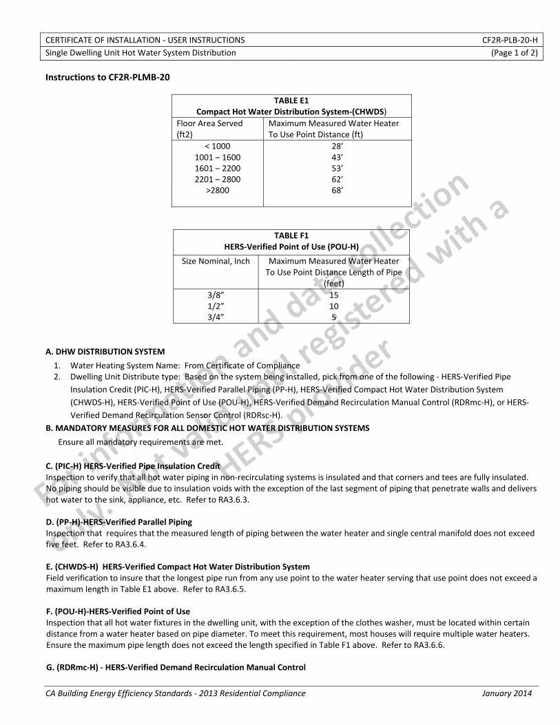
CERTIFICATE OF INSTALLATION ‐ USER INSTRUCTIONS CF2R‐PLB‐20‐H Single Dwelling Unit Hot Water System Distribution (Page 1 of 2)
CA Building Energy Efficiency Standards ‐ 2013 Residential Compliance January 2014
Instructions to CF2R‐PLMB‐20
TABLE E1Compact Hot Water Distribution System‐(CHWDS)
Floor Area Served (ft2)
Maximum Measured Water Heater To Use Point Distance (ft)
< 1000 28’1001 – 1600 43’1601 – 2200 53’2201 – 2800 62’
>2800 68’
TABLE F1HERS‐Verified Point of Use (POU‐H)
Size Nominal, Inch Maximum Measured Water Heater To Use Point Distance Length of Pipe
(feet) 3/8” 151/2” 103/4” 5
A. DHW DISTRIBUTION SYSTEM
1. Water Heating System Name: From Certificate of Compliance 2. Dwelling Unit Distribute type: Based on the system being installed, pick from one of the following ‐ HERS‐Verified Pipe
Insulation Credit (PIC‐H), HERS‐Verified Parallel Piping (PP‐H), HERS‐Verified Compact Hot Water Distribution System (CHWDS‐H), HERS‐Verified Point of Use (POU‐H), HERS‐Verified Demand Recirculation Manual Control (RDRmc‐H), or HERS‐Verified Demand Recirculation Sensor Control (RDRsc‐H).
B. MANDATORY MEASURES FOR ALL DOMESTIC HOT WATER DISTRIBUTION SYSTEMS
Ensure all mandatory requirements are met. C. (PIC‐H) HERS‐Verified Pipe Insulation Credit Inspection to verify that all hot water piping in non‐recirculating systems is insulated and that corners and tees are fully insulated. No piping should be visible due to insulation voids with the exception of the last segment of piping that penetrate walls and delivers hot water to the sink, appliance, etc. Refer to RA3.6.3. D. (PP‐H)‐HERS‐Verified Parallel Piping Inspection that requires that the measured length of piping between the water heater and single central manifold does not exceed five feet. Refer to RA3.6.4. E. (CHWDS‐H) HERS‐Verified Compact Hot Water Distribution System Field verification to insure that the longest pipe run from any use point to the water heater serving that use point does not exceed a maximum length in Table E1 above. Refer to RA3.6.5. F. (POU‐H)‐HERS‐Verified Point of Use Inspection that all hot water fixtures in the dwelling unit, with the exception of the clothes washer, must be located within certain distance from a water heater based on pipe diameter. To meet this requirement, most houses will require multiple water heaters. Ensure the maximum pipe length does not exceed the length specified in Table F1 above. Refer to RA3.6.6. G. (RDRmc‐H) ‐ HERS‐Verified Demand Recirculation Manual Control
CERTIFICATE OF INSTALLATION – DATA FIELD DEFINITIONS AND CALCULATIONS CF2R‐PLB‐20‐H Single Dwelling Unit Hot Water System Distribution (Page 3 of 3)
CA Building Energy Efficiency Standards ‐ 2013 Residential Compliance January 2014
DOCUMENTATION AUTHOR'S DECLARATION STATEMENT1. I certify that this Certificate of Installation documentation is accurate and complete.
Documentation Author Name: Documentation Author Signature:
Documentation Author Company Name: Date Signed:
Address: CEA/HERS Certification Identification (If applicable):
City/State/Zip: Phone:
RESPONSIBLE PERSON'S DECLARATION STATEMENT
I certify the following under penalty of perjury, under the laws of the State of California:
1. The information provided on this Certificate of Installation is true and correct.
2. I am eligible under Division 3 of the Business and Professions Code in the applicable classification to accept responsibility for the system design, construction, or installation of features, materials, components, or manufactured devices for the scope of work identified on this Certificate of Installation and attest to the declarations in this statement (responsible builder/installer), otherwise I am an authorized representative of the responsible builder/installer.
3. The constructed or installed features, materials, components or manufactured devices (the installation) identified on this Certificate of Installation conforms to all applicable codes and regulations, and the installation conforms to the requirements given on the plans and specifications approved by the enforcement agency.
4. I understand that a HERS rater will check the installation to verify compliance, and that if such checking identifies defects; I am required to take corrective action at my expense. I understand that Energy Commission and HERS Provider representatives will also perform quality assurance checking of installations, including those approved as part of a sample group but not checked by a HERS rater, and if those installations fail to meet the requirements of such quality assurance checking, the required corrective action and additional checking/testing of other installations in that HERS sample group will be performed at my expense.
5. I reviewed a copy of the Certificate of Compliance approved by the enforcement agency that identifies the specific requirements for the scope of construction or installation identified on this Certificate of Installation, and I have ensured that the requirements that apply to the construction or installation have been met.
6. I will ensure that a registered copy of this Certificate of Installation shall be posted, or made available with the building permit(s) issued for the building, and made available to the enforcement agency for all applicable inspections. I understand that a registered copy of this Certificate of Installation is required to be included with the documentation the builder provides to the building owner at occupancy.
Responsible Builder/Installer Name: Responsible Builder/Installer Signature:
Company Name: (Installing Subcontractor or General Contractor or Builder/Owner) Position With Company (Title):
Address: CSLB License:
City/State/Zip: Phone Date Signed:
Third Party Quality Control Program (TPQCP) Status: Name of TPQCP (if applicable):
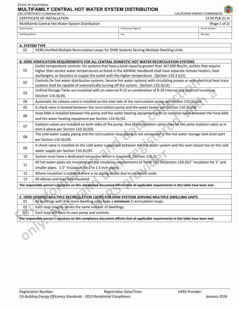
STATE OF CALIFORNIA
MULTIFAMILY CENTRAL HOT WATER SYSTEM DISTRIBUTION CEC-CF2R-PLB-21-H (Revised 06/13) CALIFORNIA ENERGY COMMISSION
CERTIFICATE OF INSTALLATION CF2R‐PLB‐21‐H Multifamily Central Hot Water System Distribution (Page 1 of 2) Project Name: Enforcement Agency: Permit Number:
Dwelling Address: City Zip Code
Registration Number: Registration Date/Time: HERS Provider: CA Building Energy Efficiency Standards ‐ 2013 Residential Compliance January 2014
A. SYSTEM TYPE 01 HERS‐Verified Multiple Recirculation Loops for DHW Systems Serving Multiple Dwelling Units
B. HERS VERIFICATION REQUIREMENTS FOR ALL CENTRAL DOMESTIC HOT WATER RECIRCULATION SYSTEMS
01 Outlet temperature controls: On systems that have a total capacity greater than 167,000 Btu/hr, outlets that require higher than service water temperatures as listed in the ASHRAE Handbook shall have separate remote heaters, heat exchangers, or boosters to supply the outlet with the higher temperature. (Section 110.3 (c)1)
02 Controls for hot water distribution systems: Service hot water systems with circulating pumps or with electrical heat trace systems shall be capable of automatically turning off the system. (Section 110.3(c)2).
03 Unfired Storage Tanks are insulated with an external R‐12 or combination of R‐16 internal and external Insulation. (Section 110.3(c)4).
04 Automatic Air release valve is installed on the inlet side of the recirculation pump per Section 110.3(c)5A.
05 A check valve is located between the recirculation pump and the water heater per Section 110.3(c)5B.
06 Hose bibb is installed between the pump and the water heating equipment with an isolation valve between the hose bibb and the water heating equipment per Section 110.3(c)5C.
07 Isolation valves are installed on both sides of the pump. One of the isolation valves may be the same isolation valve as in item 6 above per Section 110.3(c)5D.
08 The cold water supply piping and the recirculation loop piping is not connected to the hot water storage tank drain portper Section 110.3(c)5E.
09 A check valve is installed on the cold water supply line between the hot water system and the next closest tee on the cold water supply per Section 110.3(c)5F.
10 System must have a dedicated return line which is insulated. (Section 120.3)
11 All hot water pipes are insulated per the insulation requirements of Table 120.3A(Section 120.3)(1” insulation for 1” and smaller pipes. 1.5” insulation for 1 to 1.5 inch pipes)
12 Where insulation is installed there is no piping visible due to insulation voids
13 All elbows and tees fully insulated
The responsible person’s signature on this compliance document affirms that all applicable requirements in this table have been met.
C. HERS‐VERIFIED MULTIPLE RECIRCULATION LOOPS FOR DHW SYSTEMS SERVING MULTIPLE DWELLING UNITS01 All buildings with 8 or more dwelling units have aminimum 2 recirculation loops.
02 Each loop roughly serves the same number of dwellings.
03 Each loop will have its own pump and controls
The responsible person’s signature on this compliance document affirms that all applicable requirements in this table have been met.
STATE OF CALIFORNIA
MULTIFAMILY CENTRAL HOT WATER SYSTEM DISTRIBUTION CEC-CF2R-PLB-21-H (Revised 06/13) CALIFORNIA ENERGY COMMISSION
CERTIFICATE OF INSTALLATION CF2R‐PLB‐21‐H Multifamily Central Hot Water System Distribution (Page 2 of 2) Project Name: Enforcement Agency: Permit Number:
Dwelling Address: City Zip Code
Registration Number: Registration Date/Time: HERS Provider: CA Building Energy Efficiency Standards ‐ 2013 Residential Compliance January 2014
DOCUMENTATION AUTHOR'S DECLARATION STATEMENT1. I certify that this Certificate of Installation documentation is accurate and complete.
Documentation Author Name: Documentation Author Signature:
Documentation Author Company Name: Date Signed:
Address: CEA/HERS Certification Identification (If applicable):
City/State/Zip: Phone:
RESPONSIBLE PERSON'S DECLARATION STATEMENT
I certify the following under penalty of perjury, under the laws of the State of California:
1. The information provided on this Certificate of Installation is true and correct.
2. I am eligible under Division 3 of the Business and Professions Code in the applicable classification to accept responsibility for the system design, construction, or installation of features, materials, components, or manufactured devices for the scope of work identified on this Certificate of Installation and attest to the declarations in this statement (responsible builder/installer), otherwise I am an authorized representative of the responsible builder/installer.
3. The constructed or installed features, materials, components or manufactured devices (the installation) identified on this Certificate of Installation conforms to all applicable codes and regulations, and the installation conforms to the requirements given on the plans and specifications approved by the enforcement agency.
4. I understand that a HERS rater will check the installation to verify compliance, and that if such checking identifies defects; I am required to take corrective action at my expense. I understand that Energy Commission and HERS Provider representatives will also perform quality assurance checking of installations, including those approved as part of a sample group but not checked by a HERS rater, and if those installations fail to meet the requirements of such quality assurance checking, the required corrective action and additional checking/testing of other installations in that HERS sample group will be performed at my expense.
5. I reviewed a copy of the Certificate of Compliance approved by the enforcement agency that identifies the specific requirements for the scope of construction or installation identified on this Certificate of Installation, and I have ensured that the requirements that apply to the construction or installation have been met.
6. I will ensure that a registered copy of this Certificate of Installation shall be posted, or made available with the building permit(s) issued for the building, and made available to the enforcement agency for all applicable inspections. I understand that a registered copy of this Certificate of Installation is required to be included with the documentation the builder provides to the building owner at occupancy.
Responsible Builder/Installer Name: Responsible Builder/Installer Signature:
Company Name: (Installing Subcontractor or General Contractor or Builder/Owner) Position With Company (Title):
Address: CSLB License:
City/State/Zip: Phone Date Signed:
Third Party Quality Control Program (TPQCP) Status: Name of TPQCP (if applicable):
CERTIFICATE OF INSTALLATION ‐ USER INSTRUCTIONS CF2R‐PLB‐21‐H Multifamily Central Hot Water System Distribution (Page 1 of 1)
CA Building Energy Efficiency Standards ‐ 2013 Residential Compliance January 2014
Instructions to CF2R‐PLB‐21
A. SYSTEM TYPE
This form is used for HERS verification credit for Multiple Recirculation Loop Designs for DHW Systems Serving Multiple Dwelling Units defined in RA3.6.9.
B. MANDATORY MEASURES FOR ALL DOMESTIC HOT WATER DISTRIBUTION SYSTEMS
Ensure all mandatory requirements are met.
C. HERS‐VERIFIED MULTIPLE RECIRCULATION LOOPS FOR DHW SYSTEMS SERVING MULTIPLE DWELLING UNITS
This measure requires on site HERS verification that at least two central recirculation loops are included in the system design. This credit is available to buildings with 8 or more units. The recirculation loops must be relatively equal in length and supply approximately the same number of dwelling units.
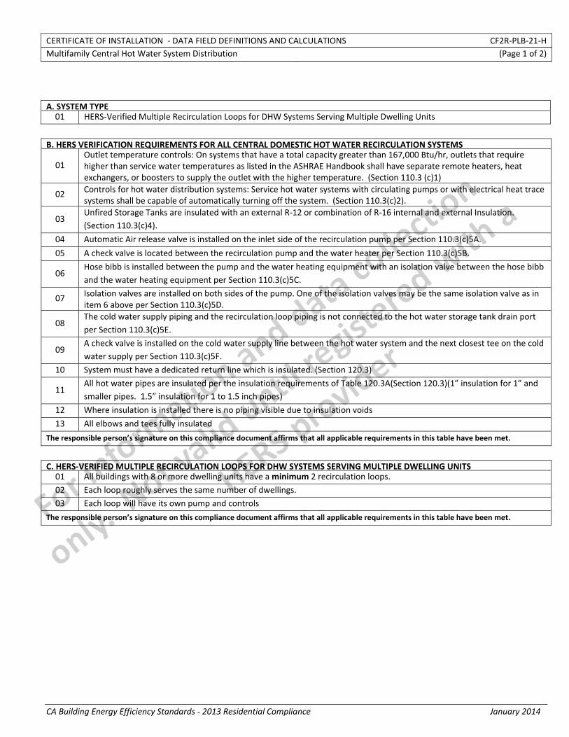
CERTIFICATE OF INSTALLATION ‐ DATA FIELD DEFINITIONS AND CALCULATIONS CF2R‐PLB‐21‐H Multifamily Central Hot Water System Distribution (Page 1 of 2)
CA Building Energy Efficiency Standards ‐ 2013 Residential Compliance January 2014
A. SYSTEM TYPE 01 HERS‐Verified Multiple Recirculation Loops for DHW Systems Serving Multiple Dwelling Units
B. HERS VERIFICATION REQUIREMENTS FOR ALL CENTRAL DOMESTIC HOT WATER RECIRCULATION SYSTEMS
01 Outlet temperature controls: On systems that have a total capacity greater than 167,000 Btu/hr, outlets that require higher than service water temperatures as listed in the ASHRAE Handbook shall have separate remote heaters, heat exchangers, or boosters to supply the outlet with the higher temperature. (Section 110.3 (c)1)
02 Controls for hot water distribution systems: Service hot water systems with circulating pumps or with electrical heat trace systems shall be capable of automatically turning off the system. (Section 110.3(c)2).
03 Unfired Storage Tanks are insulated with an external R‐12 or combination of R‐16 internal and external Insulation. (Section 110.3(c)4).
04 Automatic Air release valve is installed on the inlet side of the recirculation pump per Section 110.3(c)5A.
05 A check valve is located between the recirculation pump and the water heater per Section 110.3(c)5B.
06 Hose bibb is installed between the pump and the water heating equipment with an isolation valve between the hose bibband the water heating equipment per Section 110.3(c)5C.
07 Isolation valves are installed on both sides of the pump. One of the isolation valves may be the same isolation valve as in item 6 above per Section 110.3(c)5D.
08 The cold water supply piping and the recirculation loop piping is not connected to the hot water storage tank drain portper Section 110.3(c)5E.
09 A check valve is installed on the cold water supply line between the hot water system and the next closest tee on the cold water supply per Section 110.3(c)5F.
10 System must have a dedicated return line which is insulated. (Section 120.3)
11 All hot water pipes are insulated per the insulation requirements of Table 120.3A(Section 120.3)(1” insulation for 1” and smaller pipes. 1.5” insulation for 1 to 1.5 inch pipes)
12 Where insulation is installed there is no piping visible due to insulation voids
13 All elbows and tees fully insulated
The responsible person’s signature on this compliance document affirms that all applicable requirements in this table have been met.
C. HERS‐VERIFIED MULTIPLE RECIRCULATION LOOPS FOR DHW SYSTEMS SERVING MULTIPLE DWELLING UNITS01 All buildings with 8 or more dwelling units have aminimum 2 recirculation loops.
02 Each loop roughly serves the same number of dwellings.
03 Each loop will have its own pump and controls
The responsible person’s signature on this compliance document affirms that all applicable requirements in this table have been met.
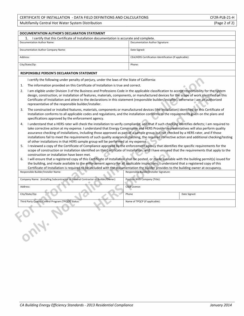
CERTIFICATE OF INSTALLATION ‐ DATA FIELD DEFINITIONS AND CALCULATIONS CF2R‐PLB‐21‐H Multifamily Central Hot Water System Distribution (Page 2 of 2)
CA Building Energy Efficiency Standards ‐ 2013 Residential Compliance January 2014
DOCUMENTATION AUTHOR'S DECLARATION STATEMENT1. I certify that this Certificate of Installation documentation is accurate and complete.
Documentation Author Name: Documentation Author Signature:
Documentation Author Company Name: Date Signed:
Address: CEA/HERS Certification Identification (If applicable):
City/State/Zip: Phone:
RESPONSIBLE PERSON'S DECLARATION STATEMENT
I certify the following under penalty of perjury, under the laws of the State of California:
1. The information provided on this Certificate of Installation is true and correct.
2. I am eligible under Division 3 of the Business and Professions Code in the applicable classification to accept responsibility for the system design, construction, or installation of features, materials, components, or manufactured devices for the scope of work identified on this Certificate of Installation and attest to the declarations in this statement (responsible builder/installer), otherwise I am an authorized representative of the responsible builder/installer.
3. The constructed or installed features, materials, components or manufactured devices (the installation) identified on this Certificate of Installation conforms to all applicable codes and regulations, and the installation conforms to the requirements given on the plans and specifications approved by the enforcement agency.
4. I understand that a HERS rater will check the installation to verify compliance, and that if such checking identifies defects; I am required to take corrective action at my expense. I understand that Energy Commission and HERS Provider representatives will also perform quality assurance checking of installations, including those approved as part of a sample group but not checked by a HERS rater, and if those installations fail to meet the requirements of such quality assurance checking, the required corrective action and additional checking/testing of other installations in that HERS sample group will be performed at my expense.
5. I reviewed a copy of the Certificate of Compliance approved by the enforcement agency that identifies the specific requirements for the scope of construction or installation identified on this Certificate of Installation, and I have ensured that the requirements that apply to the construction or installation have been met.
6. I will ensure that a registered copy of this Certificate of Installation shall be posted, or made available with the building permit(s) issued for the building, and made available to the enforcement agency for all applicable inspections. I understand that a registered copy of this Certificate of Installation is required to be included with the documentation the builder provides to the building owner at occupancy.
Responsible Builder/Installer Name: Responsible Builder/Installer Signature:
Company Name: (Installing Subcontractor or General Contractor or Builder/Owner) Position With Company (Title):
Address: CSLB License:
City/State/Zip: Phone Date Signed:
Third Party Quality Control Program (TPQCP) Status: Name of TPQCP (if applicable):
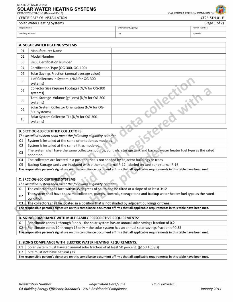
STATE OF CALIFORNIA
SOLAR WATER HEATING SYSTEMS CEC-CF2R-STH-01-E (Revised 06/13) CALIFORNIA ENERGY COMMISSION
CERTIFICATE OF INSTALLATION CF2R‐STH‐01‐E Solar Water Heating Systems (Page 1 of 2) Project Name: Enforcement Agency: Permit Number:
Dwelling Address: City Zip Code
Registration Number: Registration Date/Time: HERS Provider: CA Building Energy Efficiency Standards ‐ 2013 Residential Compliance January 2014
A. SOLAR WATER HEATING SYSTEMS
01 Manufacturer Name
02 Model Number
03 SRCC Certification Number
04 Certification Type (OG‐300, OG‐100)
05 Solar Savings Fraction (annual average value)
06 # of Collectors in System (N/A for OG‐300 systems)
07 Collector Size (Square Footage) (N/A for OG‐300 systems)
08 Total Storage Volume (gallons) (N/A for OG‐300 systems)
09 Solar System Collector Orientation (N/A for OG‐300 systems)
10 Solar System Collector Tilt (N/A for OG‐300 systems)
B. SRCC OG‐100 CERTIFIED COLLECTORS The installed system shall meet the following eligibility criteria: 01 System is installed at the same orientation as modeled.02 System is installed at the same tilt as modeled.
03 The system shall have the same collectors, pumps, controls, storage tank and backup water heater fuel type as the rated condition.
04 The collectors are located in a position that is not shaded by adjacent buildings or trees. 05 Backup Storage tanks are insulated with either an internal R‐12 (labeled on tank) or external R‐16 The responsible person’s signature on this compliance document affirms that all applicable requirements in this table have been met.
C. SRCC OG‐300 CERTIFIED SYSTEMS The installed system shall meet the following eligibility criteria: 01 The collectors shall face within 35 degrees of south and be tilted at a slope of at least 3:12
02 The system shall have the same collectors, pumps, controls, storage tank and backup water heater fuel type as the rated condition.
03 The collectors shall be located in a position that is not shaded by adjacent buildings or trees. The responsible person’s signature on this compliance document affirms that all applicable requirements in this table have been met.
D. SIZING COMPLIANCE WITH MULTIFAMILY PRESCRIPTIVE REQUIREMENTS:01 For climate zones 1 through 9 only ‐ the solar system has an annual solar savings fraction of 0.2 02 For climate zones 10 through 16 only – the solar system has an annual solar savings fraction of 0.35 The responsible person’s signature on this compliance document affirms that all applicable requirements in this table have been met.
E. SIZING COMPLIANCE WITH ELECTRIC WATER HEATING REQUIREMENTS:01 Solar System must have an annual solar fraction of at least 50 percent. (§150.1(c)8D)02 Site must not have natural gas The responsible person’s signature on this compliance document affirms that all applicable requirements in this table have been met.
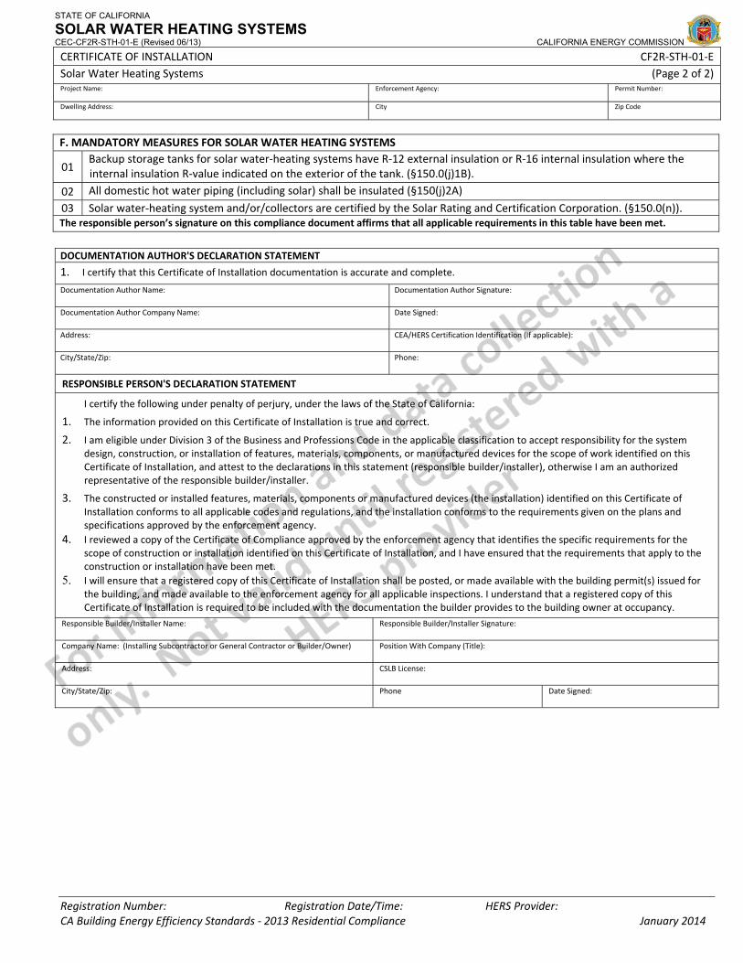
STATE OF CALIFORNIA
SOLAR WATER HEATING SYSTEMS CEC-CF2R-STH-01-E (Revised 06/13) CALIFORNIA ENERGY COMMISSION
CERTIFICATE OF INSTALLATION CF2R‐STH‐01‐E Solar Water Heating Systems (Page 2 of 2) Project Name: Enforcement Agency: Permit Number:
Dwelling Address: City Zip Code
Registration Number: Registration Date/Time: HERS Provider: CA Building Energy Efficiency Standards ‐ 2013 Residential Compliance January 2014
F. MANDATORY MEASURES FOR SOLAR WATER HEATING SYSTEMS
01 Backup storage tanks for solar water‐heating systems have R‐12 external insulation or R‐16 internal insulation where the internal insulation R‐value indicated on the exterior of the tank. (§150.0(j)1B).
02 All domestic hot water piping (including solar) shall be insulated (§150(j)2A)
03 Solar water‐heating system and/or/collectors are certified by the Solar Rating and Certification Corporation. (§150.0(n)).The responsible person’s signature on this compliance document affirms that all applicable requirements in this table have been met.
DOCUMENTATION AUTHOR'S DECLARATION STATEMENT
1. I certify that this Certificate of Installation documentation is accurate and complete.
Documentation Author Name: Documentation Author Signature:
Documentation Author Company Name: Date Signed:
Address: CEA/HERS Certification Identification (If applicable):
City/State/Zip: Phone:
RESPONSIBLE PERSON'S DECLARATION STATEMENT
I certify the following under penalty of perjury, under the laws of the State of California:
1. The information provided on this Certificate of Installation is true and correct.
2. I am eligible under Division 3 of the Business and Professions Code in the applicable classification to accept responsibility for the system design, construction, or installation of features, materials, components, or manufactured devices for the scope of work identified on this Certificate of Installation, and attest to the declarations in this statement (responsible builder/installer), otherwise I am an authorized representative of the responsible builder/installer.
3. The constructed or installed features, materials, components or manufactured devices (the installation) identified on this Certificate of Installation conforms to all applicable codes and regulations, and the installation conforms to the requirements given on the plans and specifications approved by the enforcement agency.
4. I reviewed a copy of the Certificate of Compliance approved by the enforcement agency that identifies the specific requirements for the scope of construction or installation identified on this Certificate of Installation, and I have ensured that the requirements that apply to the construction or installation have been met.
5. I will ensure that a registered copy of this Certificate of Installation shall be posted, or made available with the building permit(s) issued for the building, and made available to the enforcement agency for all applicable inspections. I understand that a registered copy of this Certificate of Installation is required to be included with the documentation the builder provides to the building owner at occupancy.
Responsible Builder/Installer Name: Responsible Builder/Installer Signature:
Company Name: (Installing Subcontractor or General Contractor or Builder/Owner) Position With Company (Title):
Address: CSLB License:
City/State/Zip: Phone Date Signed:
CERTIFICATE OF INSTALLATION ‐ USER INSTRUCTIONS CF2R‐STH‐01‐E Solar Water Heating Systems (Page 1 of 1)
CA Building Energy Efficiency Standards ‐ 2013 Residential Compliance January 2014
Installer Instructions to CF2R‐STH‐01 SOLAR HOT WATER HEATING SYSTEMS
1. Manufacturer Name ‐ From Certificate of Compliance CF1R‐STH‐01E or CF1R‐STH‐02E 2. Model Number ‐ From Certificate of Compliance CF1R‐STH‐01E or CF1R‐STH‐02E 3. SRCC Certification Number ‐ From Certificate of Compliance CF1R‐STH‐01E or CF1R‐STH‐02E 4. Certification Type – Select either OG100 or OG 300 test procedure based on CF1R submitted. For Systems that use the
OG‐100 method the program used to calculate the solar fraction should be listed. 5. Solar Fraction ‐ From Certificate of Compliance CF1R‐STH‐01E or CF1R‐STH‐02E 6. Number of Collectors ‐ From Certificate of Compliance CF1R‐STH‐01E or CF1R‐STH‐02E 7. Collector Size ‐ From Certificate of Compliance CF1R‐STH‐01E or CF1R‐STH‐02E 8. Total Storage Volume – Total gallons for water heater and supplemental storage tanks. 9. Collector System orientation ‐ From Certificate of Compliance CF1R‐STH‐01E or CF1R‐STH‐02E 10. Collector system tilt ‐ From Certificate of Compliance CF1R‐STH‐01E or CF1R‐STH‐02E
SRCC OG‐100 CERTIFIED COLLECTORS ‐ the installed system shall meet the following eligibility criteria
1. Collector System orientation from true south is within 5 degrees of the value listed above. Declination from true north for the site should be calculated and included in this measurement
2. Collector should be modeled with a tilt within 10 degrees of the value listed above. 3. The system shall have the same collectors, pumps, controls, storage tank and backup water heater fuel type as the
rated condition. 4. The collectors shall be located in a position that is not shaded by adjacent buildings or trees between 9:00 AM and
3:00 PM. Inspect site to determine if any structural component of the building, adjacent structures, or tree may shade the collector area.
5. Backup Storage tanks are insulated with either an internal R‐13 (labeled on tank) or external R‐16 SRCC OG‐300 CERTIFIED SYSTEMS ‐ the installed system shall meet the following eligibility criteria:
1. Collector System orientation shall be within 35 degree from true south Declination from true north for the site should be calculated and included in this measurement.
2. Collectors should be tilted be tilted at a slope of at least 3:12. 3. The system shall have the same collectors, pumps, controls, storage tank and backup water heater fuel type as the
rated condition. 4. The collectors shall be located in a position that is not shaded by adjacent buildings or trees between 9:00 AM and
3:00 PM. Inspect site to determine if any structural component of the building, adjacent structures, SIZING COMPLIANCE WITH MULTIFAMILY PRESCRIPTIVE REQUIREMENTS
1. For climate zones 1 through 9 only ‐ the solar system has an annual solar savings fraction of 0.2. For climate zones 10 through 16 only – the solar system has an annual solar savings fraction of 0.35
SIZING COMPLIANCE WITH MULTIFAMILY PRESCRIPTIVE REQUIREMENTS
1. Solar System must have an annual solar fraction of at least 50 percent. 2. The site must not have natural gas available, meaning that unless right of way is not reasonable attainable natural gas
supply lines cannot be located within 100 feet or under the street, whichever is closer.
MANDATORY MEASURES FOR SOLAR WATER HEATING SYSTEMS 1. Verify that collectors are SRCC certified 2. Verify that all storage tanks that are part of the solar system are insulated with either R‐12 external insulation or
labeled that they have at least R‐19 internal insulation 3. Verify that all piping in the solar system meets minimal insulation levels per (§150(j)2A)
CERTIFICATE OF INSTALLATION ‐ DATA FIELD DEFINITIONS AND CALCULATIONS CF2R‐STH‐01‐E 1 Solar Water Heating Systems (Page 2 of 2)
CA Building Energy Efficiency Standards ‐ 2013 Residential Compliance January 2014
F. MANDATORY MEASURES FOR SOLAR WATER HEATING SYSTEMS
01 Backup storage tanks for solar water‐heating systems have R‐12 external insulation or R‐16 internal insulation where the internal insulation R‐value indicated on the exterior of the tank. (§150.0(j)1B).
02 All domestic hot water piping (including solar) shall be insulated (§150(j)2A)
03 Solar water‐heating system and/or/collectors are certified by the Solar Rating and Certification Corporation. (§150.0(n)).The responsible person’s signature on this compliance document affirms that all applicable requirements in this table have been met.
Documentation Author's Declaration Statement
1. I certify that this Certificate of Installation documentation is accurate and complete.
Documentation Author Name: Documentation Author Signature:
Documentation Author Company Name: Date Signed:
Address: CEA/HERS Certification Identification (If applicable):
City/State/Zip: Phone:
Responsible Person's Declaration statement I certify the following under penalty of perjury, under the laws of the State of California: 1. The information provided on this Certificate of Installation is true and correct. 2. I am eligible under Division 3 of the Business and Professions Code in the applicable classification to accept responsibility for
the system design, construction, or installation of features, materials, components, or manufactured devices for the scope of work identified on this Certificate of Installation, and attest to the declarations in this statement (responsible builder/installer), otherwise I am an authorized representative of the responsible builder/installer.
3. The constructed or installed features, materials, components or manufactured devices (the installation) identified on this Certificate of Installation conforms to all applicable codes and regulations, and the installation conforms to the requirements given on the plans and specifications approved by the enforcement agency.
4. I reviewed a copy of the Certificate of Compliance approved by the enforcement agency that identifies the specific requirements for the scope of construction or installation identified on this Certificate of Installation, and I have ensured that the requirements that apply to the construction or installation have been met.
5. I will ensure that a registered copy of this Certificate of Installation shall be posted, or made available with the building permit(s) issued for the building, and made available to the enforcement agency for all applicable inspections. I understand that a registered copy of this Certificate of Installation is required to be included with the documentation the builder provides to the building owner at occupancy.
Responsible Builder/Installer Name: Responsible Builder/Installer Signature:
Company Name: (Installing Subcontractor or General Contractor or Builder/Owner)
Position With Company (Title):
Address: CSLB License:
City/State/Zip: Phone Date Signed: