1.step PMIT start + initial project data input Concept Concept.
State of Art and Initial Concept Requirements
D1.1
RETINA Grant: 699370 Call: H2020-SESAR-2015-1 Topic: Sesar-06-2015 Consortium coordinator: UNIBO Edition date: [06 Sept. 2016] Edition: [00.01.00]
EXPLORATORY RESEARCH Ref. Ares(2016)5158626 - 10/09/2016

EDITION [00.01.00]
2
This project has received funding from the SESAR Joint Undertaking under grant agreement No 699370 under European Union’s Horizon 2020 research and innovation programme.
Authoring & Approval
Authors of the document
Name/Beneficiary Position/Title Date
Alan Groskreutz/CRIDA Project Member 19/08/2016
Steven Bancroft/EUROCONTROL Project Member 19/08/2016
Sara Bagassi/UNIBO Project Leader 19/08/2016
Robin Houtmeyers/LUCIAD Project Member 19/08/2016
Giancarlo Ferrara/ENAV Project Member 19/08/2016
Carlo Alfredo Persiani/ENAV Project Member 19/08/2016
Antonio Nuzzo/ENAV Project Member 19/08/2016
Ornella Troise/SICTA-ENAV Project Member 19/08/2016
Diego Bellopede/ SICTA-ENAV Project Member 19/08/2016
Reviewers internal to the project
Name/Beneficiary Position/Title Date
Alan Groskreutz/CRIDA Project Member 06/09/2016
Steven Bancroft/EUROCONTROL Project Member 06/09/2016
Sara Bagassi/UNIBO Project Leader 06/09/2016
Robin Houtmeyers/LUCIAD Project Member 06/09/2016
Giancarlo Ferrara/ENAV Project Member 06/09/2016
Carlo Alfredo Persiani/ENAV Project Member 19/08/2016
Antonio Nuzzo/ENAV Project Member 19/08/2016
Ornella Troise/SICTA-ENAV Project Member 19/08/2016
Diego Bellopede/ SICTA-ENAV Project Member 19/08/2016
Approved for submission to the SJU By — Representatives of beneficiaries involved in the project
Name/Beneficiary Position/Title Date
Sara Bagassi/UNIBO Project Leader 08/09/2016
Alan Groskreutz /CRIDA Project Member 08/09/2016
Steven Bancroft/EUROCONTROL Project Member 09/09/2016
Tom Nuydens/Luciad Project Member 09/09/2016
Ornella Troise/SICTA Project Member 09/09/2016

STATE OF ART AND INITIAL CONCEPT REQUIREMENTS
This project has received funding from the SESAR Joint Undertaking under grant agreement No 699370 under European Union’s Horizon 2020 research and innovation programme.
3
Rejected By - Representatives of beneficiaries involved in the project
Name/Beneficiary Position/Title Date
Document History
Edition Date Status Author Justification
00.00.01 19/05/2016 Draft Alan Groskreutz New Document
00.00.02 25/05/2016 Draft Steven Bancroft Section 4 added
00.00.03 23/06/2016 Draft Nicola Masotti Section 3 added
00.00.04 21/07/2016 Draft Various Authors Section 2 added
00.00.05 27/07/2016 Draft Ornella Troise Section 5 added
00.01.00 06/09/2016 Final Alan Groskreutz Internal review
EDITION [00.01.00]
4
This project has received funding from the SESAR Joint Undertaking under grant agreement No 699370 under European Union’s Horizon 2020 research and innovation programme.
RETINA Resilient Synthetic Vision for Advanced Control Tower Air Navigation Service Provision This project has received funding from the SESAR JU under grant agreement No 699370.
Executive Summary
This document sets up the baseline for the other project work packages, identifying the state of the art in terms of displays technologies, data sources and standards. Also, a task analysis of control tower working environment is presented in order to identify the needs and constraints for the future synthetic vision and V/AR tools. The task analysis covers both standard and low visibility conditions. This document also lists operational procedures, requirements and guidelines from a human factors and ergonomic perspective. All of these results will serve as input to the concept development performed in WP2.

STATE OF ART AND INITIAL CONCEPT REQUIREMENTS
This project has received funding from the SESAR Joint Undertaking under grant agreement No 699370 under European Union’s Horizon 2020 research and innovation programme.
5
Table of Contents
Executive Summary .................................................................................................................. 4
1. Introduction ............................................................................................................... 7
1.1 RETINA project overview ............................................................................................... 7
1.2 Document Scope ........................................................................................................... 7
1.3 Intended Audience ........................................................................................................ 8
1.4 Acronym List ................................................................................................................. 8
2 Review of Existing Sensing Technologies and Data Provision Standards .................... 13
2.1 Technology and literature ............................................................................................ 13
2.2 Technology #1 - RADAR ................................................................................................ 14
2.3 Technology #2 - LIDAR ................................................................................................. 14
2.4 Technology #3 – ADS-B ................................................................................................ 15
2.5 Technology #4 – Visible light camera ............................................................................ 18
2.6 Technology #5 – Infra-red camera ................................................................................ 19
2.7 Technology #6 – A-SMGCS ........................................................................................... 21
2.8 Technology #7 – Audio cues ......................................................................................... 22
2.9 Technology #8 – MET data ........................................................................................... 22
3 Review of Existing Synthetic Vision Systems and Virtual/Augmented Reality Display Techniques ..................................................................................................................... 25
3.1 Historical Background (VR, AR, SV) ............................................................................... 25
3.2 Fundamentals of Virtual Reality, Augmented Reality and Synthetic Vision (depth perception, depth cues, collimation, registration and more) .................................................... 30
3.3 User presence and eye tracking technologies ............................................................... 37
3.4 Taxonomy of V/AR and SV Technologies ...................................................................... 43
3.5 Technology #1 – Head Mounted Displays (both VR and See-Through) ........................... 49
3.6 Technology #2 – Hand Held Displays (both physical and virtual) .................................... 61
3.7 Technology #3 – Spatial Displays (VR, See-Through, SV and holographic displays) ......... 64
3.8 Technology #4 – Object-Projected Displays (i.e. images projected on objects) ............... 67
3.9 Technology #5 – Volumetric Displays............................................................................ 68

EDITION [00.01.00]
6
This project has received funding from the SESAR Joint Undertaking under grant agreement No 699370 under European Union’s Horizon 2020 research and innovation programme.
4 Task analysis of the ATC service provision from the control tower ............................. 71
4.1 Task Analysis Overview ................................................................................................ 71
4.2 Standard and Low Visibility Task Analysis ..................................................................... 71
4.3 Operational Requirements ........................................................................................... 80
5 Human Factors & Ergonomics ................................................................................... 90
5.1 Technology #1 – Head Mounted Displays (both VR and See-Through) ........................... 92
5.2 Technology #2 – Hand Held Displays (both physical and augmented) ............................ 96
5.3 Technology #3 – Spatial Displays (VR, See-Through, SV and holographic displays) ......... 99
5.4 Technology #4 – Object-Projected Displays (i.e. images projected on objects) .............. 103
5.5 Technology #5 – Volumetric Displays........................................................................... 105
5.6 Human Factors and Ergonomics Recommendations ..................................................... 107
6 References .............................................................................................................. 108
STATE OF ART AND INITIAL CONCEPT REQUIREMENTS
This project has received funding from the SESAR Joint Undertaking under grant agreement No 699370 under European Union’s Horizon 2020 research and innovation programme.
7
1. Introduction
1.1 RETINA project overview
The RETINA project consists of a research and innovation action that deals with the development of innovative tools for the airport control tower and, as such, relates to ER-06-2015 – High Performing Airport Operations – Improved Visualisation and Awareness.
The RETINA project takes the idea of augmented vision and investigates its application to on-the-site control towers through the use of synthetic vision, it investigates the placement of additional information such as flight tags, runway layout, and warning detection over the actual out the window view, that the controller has. Therefore, RETINA builds upon the technology previously developed in SESAR and provide new overlays as well.
From a technological perspective, RETINA investigates two different augmented reality (AR) systems: Conformal Head-Up Displays (which could be made to coincide with the tower windows) and See-Through Head-Mounted Displays (ST-HMD). A dissimilar third tool, i.e. a virtual reality (VR) based Table-Top interface will be conceived as well.
RETINA will deal with application-oriented research and encourage innovative and visionary ideas, effectively contributing to the SESAR 2020 Research and Innovation (R&I) cycle.
1.2 Document Scope
This document sets up the baseline for the other project work packages, identifying the state of the art in terms of displays technologies, data sources and standards. Also, a task analysis of control tower working environment is presented in order to identify the needs and constraints for the future synthetic vision and V/AR tools. The task analysis covers both standard and low visibility conditions.
It includes the results of a review of the current state of the art of sensing technologies and data provision standards. For traffic information well-established ATM surveillance systems (e.g. SMR1, ASR2, etc.) are addressed, along with recent technology developed for Remote Tower Operations
1 Surface Movement Radar 2 Airport Surveillance Radar

EDITION [00.01.00]
8
This project has received funding from the SESAR Joint Undertaking under grant agreement No 699370 under European Union’s Horizon 2020 research and innovation programme.
(e.g. standard and infrared cameras). For weather related information and digital NOTAM3 the project will look at SWIM. Also, technologies to sense the controllers’ presence, position and line of sight within the working environment are included.
A review of the current means to provide augment reality, either through display screens or head mounted displays, is presented. A list of technologies is included addressing the benefits and drawbacks of each one as it applies to the RETINA concept. An analysis of the various technologies listed was performed to investigate the ergonomic viability and risks and benefits of each from a human factors perspective. Also included is a task analysis of the provision of ATC service from the control tower in both standard and low visibility conditions focusing on how the RETINA concept would impact them. This review will produce operational requirements for the synthetic vision systems and concepts to be developed in WP2.
1.3 Intended Audience
This document was developed primarily as an input for WP2 in order to select and design the solutions proposed and further develop the conceptual requirements. Other potential users could include airports interested in implementing these types of tools and, in general, other entities or projects that are interested in Augmented Reality systems.
1.4 Acronym List
Term Definition
ADS-B Automatic Dependent Surveillance – Broadcast
ADS-R Automatic Dependent Surveillance – Re-broadcast
AMEL Active Matrix Electroluminescent
APP APProach
AR Augmented Reality
ARA Augmented Reality Audio
A-SMGCS Advanced Surface Movement Guidance and Control System
ASR Airport Surveillance Radar
3 NOtice To AirMen
STATE OF ART AND INITIAL CONCEPT REQUIREMENTS
This project has received funding from the SESAR Joint Undertaking under grant agreement No 699370 under European Union’s Horizon 2020 research and innovation programme.
9
ATC Air Traffic Control
ATCO Air Traffic Control Operator(s)
ATM Air Traffic Management
BARS Battlefield Augmented Reality System
CDM Collaborative Decision Making
CF Climate and Forecast
CFR Crash Fire Response
CRT Cathode Ray Tube
CVS Combined Vision System
CWP Controller Working Position
DLP Digital Light Processing
DME Distance Measuring Equipment
EFVS Enhanced Flight Vision System
EOBT Estimated off Blocks Time
EVS Enhanced Vision System
FAA Federal Aviation Administration
FIR Flight Information Region
FIS-B Flight Information System – Broadcast
FLIR Forward-Looking InfraRed
FOV Field of View
FPS Flight Plan System
GML Geography Markup Language
GNSS Global Navigation Satellite System
GPS Global Positioning System

EDITION [00.01.00]
10
This project has received funding from the SESAR Joint Undertaking under grant agreement No 699370 under European Union’s Horizon 2020 research and innovation programme.
GRIB Gridded Binary
HDF Hierarchical Data Format
HMD Head Mounted Display
HMI Human Machine Interface
HUD Head Up Display
ICAO International Civil Aviation Organization
IFR Instrument Flight Rules
IWXXM ICAO Weather Information Exchange Model
LCD Liquid Crystal Display
LCoS Liquid Crystal on Silicon Displays
LVC Low Visibility Condition
LVP Low Visibility Procedure
METAR METeorological Air Report
MMR Multi-Mode Receiver
NASA National Aeronautics and Space Administration
NetCDF Network Common Data Form
NMOC Network Manager Operations Centre
NOTAM NOtice To AirMen
OCG Open Geospatial Consortium
OLED Organic Light Emitting Diode
OTW Out-the-Window
PLR Pavement Load Ratings
R&I Research and Innovation
RSD Retinal Scanning Display
SESAR Single European Sky ATM Research Programme
SID Standard Instrument Departure
STATE OF ART AND INITIAL CONCEPT REQUIREMENTS
This project has received funding from the SESAR Joint Undertaking under grant agreement No 699370 under European Union’s Horizon 2020 research and innovation programme.
11
SIGMET SIGnificant METeorologic information
SMR Surface Movement Radar
SPECI Special Weather Report
SSR Secondary Surveillance Radar
ST-HMD See-Through Head-Mounted Displays
SVS Synthetic Vision System
SVS Synthetic Vision System
SWIM System Wide Information Management
TAF Terminal Aerodrome Forecast
TIS-B Traffic Information Service – Broadcast
TSAT Target Start Up and Taxi time
V/AR Virtual/Augmented Reality
V/ARTT Virtual/Augmented Reality Tower Tool
VAC Vergence-Accommodation Conflict
VCS Visually Coupled System
VFD Vacuum Fluorescent Displays
VFR Visual Flight Rules
VHF Very High Frequency
VR Virtual Reality
WCS Web Coverage Service
WFS Web Feature Service
WMO World Meteorological Organization
WMS Web Map Service
WMTS Web Map Tile Service
EDITION [00.01.00]
12
This project has received funding from the SESAR Joint Undertaking under grant agreement No 699370 under European Union’s Horizon 2020 research and innovation programme.
WXXM Weather Information Exchange Model

STATE OF ART AND INITIAL CONCEPT REQUIREMENTS
This project has received funding from the SESAR Joint Undertaking under grant agreement No 699370 under European Union’s Horizon 2020 research and innovation programme.
13
2 Review of Existing Sensing Technologies and Data Provision Standards
A review of the current means to provide augmented reality, either through display screens or head mounted displays, is presented. A list of these technologies is included listing the benefits and drawbacks of each one as it applies to the RETINA operational concept. An analysis of the various technologies listed is performed to investigate the ergonomic viability and risks and benefits of each from a human factors perspective.
2.1 Technology and literature
In order to present an augmented reality to the controller, there must first be a source, or sources, from which to draw the information to augment their perception. The information that a controller would find helpful in carrying out of their duties would be information other than what they can make direct contact with. This information would include aircraft related information as well as weather data. The gathering of this information can generally be referred to as remote sensing as it senses information in the environment. Various technologies can be used to gather this information, but the sources specific to information that would be useful to airport tower controllers are the following:
RADAR
LIDAR
ADS-B
Visible light camera
Infra-red camera
A-SMGCS
Met data
When describing the different sensing technologies and their application to the RETINA project, the maturity of each technology will be discussed. While all of these technologies could be said to have a Technology Readiness Level of 9, many of them have not been used in this particular environment, or in the manner proposed. For the fully developed sensing technologies, the maturity level will focus on these aspects.
The literature gathered during the research on these technologies and their possible application to an augmented reality system is listed here as well as in the references section.

EDITION [00.01.00]
14
This project has received funding from the SESAR Joint Undertaking under grant agreement No 699370 under European Union’s Horizon 2020 research and innovation programme.
2.2 Technology #1 - RADAR
2.2.1 Potential usage and functions
RADAR systems, or more generally the use of radio waves, are widely used as the main source for aircraft position information (surveillance). These systems can be found in many forms such as Primary Surveillance Radar, Secondary Surveillance Radar, Mode S, and Multilateration. They all serve to show the location of the aircraft, and some, such as Mode S and Multilateration, contain information related to the specific aircraft and its flight plan. This information is necessary in order to properly place the aircraft related information and overlays in the correct location within the controller’s field of view.
2.2.2 Maturity Level
Using radio wave signals for surveillance is one of the oldest remote sensing technologies and is at a very mature state as it is used all around the world.
2.2.3 Benefits and drawbacks
The main benefit of these technologies is that they are already in use at most medium and all large airports and would not require any additional investment for their use. The drawbacks are that they are expensive to maintain, and the ground systems are not available in many smaller airports.
2.3 Technology #2 - LIDAR
2.3.1 Potential usage and functions
LIDAR is the measurement of distance by scanning an object, or area, with a laser. It has been used to profile clouds, measure winds, and study atmospheric contamination. It can do this by measuring the backscatter in the atmosphere or the scattered reflection on the ground. Doppler LIDAR can be used to measure wind speed, turbulence, and wind shear, all of which can be useful to the tower controller, especially the turbulence, which cannot be obtained through SWIM.
2.3.2 Maturity Level
While the specific implementation as a controller tool is yet to be applied, Doppler LIDAR has been used for years to measure wind and turbulence data. The data supporting the RECAT wake turbulence recatagorisation of aircraft was obtained from Doppler LIDAR systems at airports both in the US and in Europe.

STATE OF ART AND INITIAL CONCEPT REQUIREMENTS
This project has received funding from the SESAR Joint Undertaking under grant agreement No 699370 under European Union’s Horizon 2020 research and innovation programme.
15
2.3.3 Benefits and drawbacks
Doppler LIDAR could potentially give the controllers a view of where the wake turbulence actually is behind an aircraft, providing a possible safety benefit. While the technology behind Doppler LIDAR is mature and in use in many areas, including at some airports, the specific implementation as a sensing technology for controller tools has yet to be done.
2.4 Technology #3 – ADS-B
2.4.1 Potential usage and function
ADS-B (Automatic Dependent Surveillance – Broadcast) is a system that uses transmissions from aircraft to provide geographical position, pressure altitude data, positional integrity measures, flight identity, 24 bit aircraft address, velocity and other data which have been determined by airborne sensors.
Typically, the airborne position sensor is a GPS receiver, or the GPS output of a Multi-Mode Receiver (MMR). This sensor must provide integrity data that indicates the containment bound on positional errors. The altitude sensor is typically the same barometric source / air data computer source used for SSR (Secondary Surveillance Radar). Integrated GPS and inertial systems are also used. Currently inertial only sensors do not provide the required integrity data although these are likely to be provided in the future.
EDITION [00.01.00]
16
This project has received funding from the SESAR Joint Undertaking under grant agreement No 699370 under European Union’s Horizon 2020 research and innovation programme.
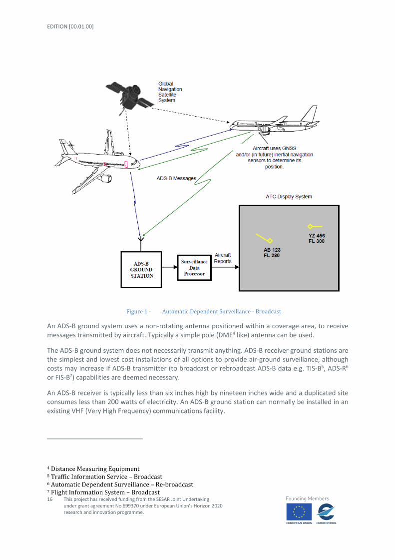
Figure 1 - Automatic Dependent Surveillance - Broadcast
An ADS-B ground system uses a non-rotating antenna positioned within a coverage area, to receive messages transmitted by aircraft. Typically a simple pole (DME4 like) antenna can be used.
The ADS-B ground system does not necessarily transmit anything. ADS-B receiver ground stations are the simplest and lowest cost installations of all options to provide air-ground surveillance, although costs may increase if ADS-B transmitter (to broadcast or rebroadcast ADS-B data e.g. TIS-B5, ADS-R6 or FIS-B7) capabilities are deemed necessary.
An ADS-B receiver is typically less than six inches high by nineteen inches wide and a duplicated site consumes less than 200 watts of electricity. An ADS-B ground station can normally be installed in an existing VHF (Very High Frequency) communications facility.
4 Distance Measuring Equipment 5 Traffic Information Service – Broadcast 6 Automatic Dependent Surveillance – Re-broadcast 7 Flight Information System – Broadcast

STATE OF ART AND INITIAL CONCEPT REQUIREMENTS
This project has received funding from the SESAR Joint Undertaking under grant agreement No 699370 under European Union’s Horizon 2020 research and innovation programme.
17
ADS-B is becoming a mandatory piece of equipment for new aircraft as part of Single European Sky regulation [1]. It is being used in Canada as part of air traffic control in certain areas [2], giving those flights a higher level of service. Its use is also mandatory in parts of Australia.
2.4.2 Benefits and drawbacks
Benefits.
Simple ground station design without transmitter.
Can be installed at sites shared with other users.
Very low ground station cost (but highly variable ADS-B avionics fitment cost).
Very high update rate.
Very high resolution.
High accuracy and integrity (airborne measurements).
Higher performance velocity vector measured by avionics and then broadcast, rather than
determined from positional data received on the ground.
Accuracy not dependent on range from ground station.
Facilitates exchange of surveillance data across FIR (Flight Information Region) boundaries.
Can be easily deployed for temporary use (emergency, special events etc.).
Can support the display of callsigns on simple display systems without interfaces to flight
planning systems since callsign is provided directly from the aircraft.
Facilitates future provision of innovative ATM services based on air-to-air ADS-B.
Drawbacks
Dependent on aircraft avionics. This can be a major issue in some environments.
Equipage rates are relatively low at this stage [21].
Systems require optimum site with unobstructed view to aircraft.
Some outages expected due to poor GPS geometry when satellites out of service, although
exposure expected to reduce in the future with use of GNSS (Global Navigation Satellite
System) augmentation & internal support.
EDITION [00.01.00]
18
This project has received funding from the SESAR Joint Undertaking under grant agreement No 699370 under European Union’s Horizon 2020 research and innovation programme.
2.5 Technology #4 – Visible light camera
2.5.1 Potential usage and functions
One way to accomplish visual surveillance in case of low visibility or in the remote tower control is to use cameras to replicate the visual view. However, in some areas the camera is inferior to the human eye and suffers from drawbacks that have a negative impact on the ability to provide air traffic services. One example is the ability to provide stereoscopic 3D visualization and so the visual separation for two or more aircraft
A way to replicate the view from a control tower is to install an array of cameras to cover the entire view, or parts of it. There are however situations in which cameras do not achieve the wanted results. If not solved it might affect the ability to provide air traffic service.
One of the situations in which it is hard for a camera to perform is when it’s faced with different light conditions in the image (e.g. a bright sky and dark ground). Another problem derives from the fact that each camera in an array produces different results since they all are faced with different light conditions.
2.5.2 Maturity Level
This technology is used to improve the human eye control and in particular to avoid blind spot, but also in the remote tower control.
Different technological solutions are currently on sale which are also able to solve the negative effects caused by applying an automatic camera control system and used in the remote tower functions.
2.5.3 Benefits and drawbacks
The main benefit of these technologies is that could be adopted by airports with no impact on the current infrastructure but only by adding an additional infrastructure to be integrated in the current system.
The main drawback of this solution is that it suffers from poor image quality, particularly for remote visual, which restricts the level of service and hence also the capacity of the airport. On the other hand most regional airports have more vehicle movements than aircraft and ground surveillance should therefore not be neglected when trying to optimize the video. Usually the Ground surveillance is considered to be the bottleneck when it comes to capacity of the airport and it is here that the visual presentation will play an important part.
The research should strive for automation to achieve good image quality, however it is foreseen to be a need for manual intervention and the manually must be comprehensible to the ATCO; otherwise they will not be used. In general the reduction of visibility, due to poor image quality, could be compared to low visibility in bad weather conditions.
The mechanisms of direct feedback you get in the image when you adjust the TV brightness might be applicable also for the settings for focus, exposure times etc by ATCO. This semi-automatic configuration should be better than an automatic approach as there is a direct relation between the

STATE OF ART AND INITIAL CONCEPT REQUIREMENTS
This project has received funding from the SESAR Joint Undertaking under grant agreement No 699370 under European Union’s Horizon 2020 research and innovation programme.
19
manual settings for the image and the awareness of applied enhancements to the picture. For example, if obligated to switch between day and night settings, the ATCO might be more aware of the current visual condition contrariwise in the automatic approach where a digital camera has automation for exposure times, shutter, ISO, gain etc should decrease the ATCO attention and the ATCO should be not really aware of the current visual condition
2.6 Technology #5 – Infra-red camera
2.6.1 Potential usage and functions
Infrared imaging provides a thermo-graphic representation of the focused area. This could be used as a supplement to the regular cameras in a remote tower and/or as additional view, to be used in darkness or in fog. An example of the image provided by an infrared camera is shown in Fig.2.
Figure 2 - Infrared view in fog
Our eyes are detectors that can only see light in some parts of the light spectrum. These parts are hence defined as the visible spectrum. There are other forms of light that the human eye cannot see. At one end of our visible range is ultraviolet light, and in the other end is infrared light. A thermal imaging camera produces an image based on the differences in thermal radiation that an object emits. All objects with a temperature above absolute zero, emits radiation visible by an infrared camera. Therefore an infrared camera isn’t affected by a dark environment.
Cameras could be placed in such a way that a desirable view could be switched between regular cameras and infrared vision. An infrared camera could also be placed on a manoeuvrable zoom camera to be manoeuvred, with ability to switch between the attached regular camera and the infrared camera. This view could then be presented either on a separate screen, where the manoeuvrable zoom camera is displayed, or overlaid in the Out-the-Window (OTW) view, at the position where the camera is pointed (see Fig.3).

EDITION [00.01.00]
20
This project has received funding from the SESAR Joint Undertaking under grant agreement No 699370 under European Union’s Horizon 2020 research and innovation programme.
Figure 3 - Example of infrared camera view merged in the OTW view
By attaching an infrared camera along with a manoeuvrable zoom camera, the robot could be manoeuvred to whichever area that is of interest.
2.6.2 Maturity Level
This technology is used to improve the human eye control and in particular to overcome the problem of visibility during night time and in the fog. Currently on sale there are different technological solutions used in the remote tower functions also if the use is not fully validated.
2.6.3 Benefits and drawbacks
The main benefit of an infrared camera is to increase the ATCO situational awareness during night time, and in fog, to increase the overall safety and stretch the optional LVP boundaries. Infrared camera usage in fog is especially useful since it can increase visibility. This is a particularly interesting area since these distances are break points for when to apply LVP. The possibility to sufficiently monitor the manoeuvring area during landings and take-offs during the night and in fog would have a positive impact on safety. The position of all vehicles can be visually confirmed, unauthorized movements can be detected and wildlife incidents can be avoided.
By using this technology all airports could expect quicker and more efficient runway checks during low visibility conditions.
The main thing to consider when implementing visual enhancements is that the ATCO must at all times be aware of the actual visual conditions. The risk otherwise is that the ATCO would make decisions based on too good information and/or give confusing directions. “Behind landing aircraft, line up runway…” is not helpful to the pilot if the landing aircraft can only be seen by the ATCO.
Equally important is that everyone else is aware of the capabilities of the remote tower concept in order to understand and respect the ATCO decision making. To switch between enhanced and normal image on the press and release of a button is one possible way to gain from the benefits while still being aware of the actual visual conditions.

STATE OF ART AND INITIAL CONCEPT REQUIREMENTS
This project has received funding from the SESAR Joint Undertaking under grant agreement No 699370 under European Union’s Horizon 2020 research and innovation programme.
21
2.7 Technology #6 – A-SMGCS
2.7.1 Potential usage and functions
A-SMGCS (Advanced Surface Movement Guidance and Control System) surveillance functions could be used to determine the identification and location of transponder equipped aircraft and mobiles as well providing alerts for possible incursions and other safety related events. It has 4 different levels of implementation.
1. A-SMGCS Level 1 (improved Surveillance) makes use of improved surveillance and procedures, covering the manoeuvring area for ground vehicles and the movement area for aircraft. The procedures concern identification and the issuance of ATC instructions and clearances. The controllers are given traffic position and identity information which is an important step forward from the traditional Surface Movement Radar (SMR) image.
2. A-SMGCS Level 2 (Surveillance + Safety Nets) adds safety nets which protect runways and designated areas and the associated procedures. Appropriate alerts are generated for the controllers in case of conflicts between all vehicles on runways and the incursion of aircraft onto designated restricted areas.
3. A-SMGCS Level 3 (Conflict Detection) involves the detection of all conflicts on the movement area as well as improved guidance and planning for use by controllers.
4. A-SMGCS Level 4 (Conflict Resolution, Automatic Planning & Guidance) provides resolutions for all conflicts and automatic planning and automatic guidance for the pilots as well as the controllers.
2.7.2 Maturity Level
A-SMGCS is currently in the process of deployment throughout Europe[4]. Level 1 is seeing delays in deployment, so it is safe to assume that level 2 deployment will also be delayed, but it is difficult to predict how long the delays will be.
2.7.3 Benefits and drawbacks
A-SMGCS allows for enhanced low visibility operations as, with the appropriate certification, the identification of aircraft can be obtained directly from the HMI (European region)[3]. As A-SMGCS, at least in level 2 and above, already includes the alert functions, the incorporation of these alerts into the display would be more easily facilitated.
A potential drawback would be that A-SMGCS systems are not being planned for installation in smaller airports.

EDITION [00.01.00]
22
This project has received funding from the SESAR Joint Undertaking under grant agreement No 699370 under European Union’s Horizon 2020 research and innovation programme.
2.8 Technology #7 – Audio cues
2.8.1 Potential usage and functions
Augmented Reality Audio (ARA) may be defined as a system having the three following characteristics:
combines real world and virtual objects
is interactive or reactive
uses 3D positioning of virtual objects
Real and virtual sound differ in where the sound originates. Real sound comes from the user's environment, and virtual sound originates from another environment, or is created artificially. ARA combines these aspects to mix the two so that the virtual sound compliments the real ones.
ARA could be used to direct the controller's attention to a warning, alarm, or direction of a call from an aircraft.
2.8.2 Maturity Level
Obviously, audio transmission is a mature technology. The reproduction of a virtual musical sound stage where the listener can place where each instrument is located has been available for decades. What would need to be developed is linking the audio message with the location of the source or object in question to be able to set the stereo imaging of the audio message (how far left or right in the controller's audio field).
2.8.3 Benefits and drawbacks
The benefit of this would be knowing in which direction to look when an alarm occurs that is not in the controller's field of view. The drawback is that it could be distracting to the controller as it is another sensory input. It also seems to be more applicable to the HMD technologies, where the audio is reproduced locally. Either that, or through the headset of the controller in order to not bother the other controllers in the room.
2.9 Technology #8 – MET data
2.9.1 Potential usage and functions
Met data provision and access is an essential aspect of SESAR’s System Wide Information Management (SWIM) implementation, assuring interoperable exchange of commonly understood meteorological information relevant for air traffic [5].
STATE OF ART AND INITIAL CONCEPT REQUIREMENTS
This project has received funding from the SESAR Joint Undertaking under grant agreement No 699370 under European Union’s Horizon 2020 research and innovation programme.
23
From a technology perspective, multiple physical data models are available to support this implementation [6]:
IWXXM (also known as ICAO8 WXXM or ICAO Weather Information Exchange Model)
o This format is a one of the primary candidates for Met data exchange in a SWIM-
enabled environment:
It is based on ICAO’s meteorological requirements with respect to METAR9,
SPECI10, TAF11 and SIGMET12 weather data products [7]. Version 2.0 (in
development) adds AIRMET, Tropical Cyclone Advisory and Volcanic Ash
Advisory data products.
Being based on OGC GML (Open Geospatial Consortium - Geography
Markup Language), it is well-suited for distribution through OGC web
services, also embraced by SWIM [6].
o Maintained by: World Meteorological Organization (WMO) and ICAO.
o Maturity: increasing. Versions 1.0 and 1.1 have been respectively released in 2013
and 2015. Version 2.0 is planned to be released August 2016.
WXXM
o This format extends IWXXM and adds additional types of weather information not
covered in IWXXM [8].
o Maintained by: Eurocontrol and FAA.
o Maturity: increasing. Version 2.0 has been released in 2015.
OGC NetCDF
o The OGC Network Common Data Form (NetCDF) standard is a self-describing data
model to represent scientific data. By means of the climate and forecast (CF)
extension, it is widely used in climate and weather forecasts systems [9].
o Maintained by: OGC.
o Maturity: widespread format, good adoption in industry.
GRIB2
o GRIB or Gridded Binary is a data format used in meteorology to store historical and
forecast weather data.
o Maintained by: WMO.
o Maturity: widespread format, good adoption in industry.
HDF5:
8 International Civil Aviation Organization 9 METeorological Air Report 10 Special Weather Report 11 Terminal Aerodrome Forecast 12 SIGnificant METeorologic information
EDITION [00.01.00]
24
This project has received funding from the SESAR Joint Undertaking under grant agreement No 699370 under European Union’s Horizon 2020 research and innovation programme.
o HDF5 (Hierarchical Data Format) includes a data model capable of representing
complex data objects and a wide variety of metadata.
o Maintained by: http://www.hdfgroup.org
o Maturity: widespread format, good adoption in industry (although limited in a SWIM
environment).
For data exchange, SWIM actively focuses on OGC web services, including WFS13, WMS14, WMTS15 and WCS16 [6]. By definition, each OGC web service type has its own characteristics and suitable data model exchange types. WMS and WMTS can be used to access rendered versions of the data, using bitmap format such as JPEG and PNG. WFS and WCS on the other hand focus on exchanging the native data:
WFS: focuses on exchange of GML-based vector data: IWXXM, WXXM
WCS: focuses on exchange of raster data: NetCDF, GRIB2, HDF5
To ease the discovery of actual Met (and other aviation-related) data and services in a SWIM environment, SESAR deployed an online catalogue, called the SWIM Registry:http://eur-registry.swim.aero/.
2.9.2 Maturity Level
The provision of MET data to the control tower is a mature service. What is not mature yet is providing this service via SWIM, or the integration of this data into a visualization tool that is not an overlay of a radar screen. The SWIM services are being developed and standardized both within the SESAR program and internationally.
2.9.3 Benefits and drawbacks
MET data such as the windspeed and direction, LVP category, wake vortexes, etc. could be helpful for the controller to have as a piece of data off to the side of their field of view. The drawback of having this type of information in the controller's field of view is that it may crowd out more important information. This trade off would have to be validated.
13 Web Feature Service 14 Web Map Service 15 Web Map Tile Service 16 Web Coverage Service

STATE OF ART AND INITIAL CONCEPT REQUIREMENTS
This project has received funding from the SESAR Joint Undertaking under grant agreement No 699370 under European Union’s Horizon 2020 research and innovation programme.
25
3 Review of Existing Synthetic Vision Systems and Virtual/Augmented Reality Display Techniques
A review of the current means to provide augmented reality, either through display screens or head mounted displays, will be performed. Products that have development kits already distributed will be noted for further investigation. A list of these technologies will be produced listing the benefits and drawbacks of each one as it applies to the RETINA operational concept
3.1 Historical Background (VR, AR, SV)
Historically, displays have been mainly unidirectional like pictures or sign posts. But since the Industrial Revolution, and more intensively since the widespread use of computer-based devices, displays have become increasingly interactive. Hence, users both receive and send signals via displays. The purpose of a display, however, is not the transmission of information but of meaning. Information transmission is only a necessary but not a sufficient condition for a successful display. The meaning is provided by the semantic context surrounding the receiver and the sender through their knowledge of other signals with which the signal is semantically and syntactically associated. Because the measurement of the quantity of information in a signal is determined by its “surprise value” or unexpectedness, its information content, though important, is not necessarily closely related to its meaning. Meaning, in fact, is a kind of dual of information. When a signal or message has a significant semantic context, the transmission of subsequent specific signals becomes more expected and their information content is consequently reduced by the redundancy.
In order to provide a history of Virtual and Augmented Realities, the terms first need to be defined. Virtual Reality refers to participating in a synthetic environment rather than strictly observing one [16]. Two technological dimensions that contribute to the sensation of reality are vividness and interactivity.[15]
Augmented Reality is the real-time superposition of synthetic, or computer-generated images, onto real world images[12][14]. This can be accomplished through a variety of means, which are detailed in Section 3.4. Defining Synthetic Vision can be a bit more difficult, since many different systems can fall under this broad title. These systems can include Enhanced Vision (electronic means to provide a display of the

EDITION [00.01.00]
26
This project has received funding from the SESAR Joint Undertaking under grant agreement No 699370 under European Union’s Horizon 2020 research and innovation programme.
forward external scene topography through the use of imaging sensors), Enhanced Flight Vision (inclusion of flight data such as airspeed, aircraft attitude, heading, altitude, etc.), and Combined Vision (Database-driven synthetic vision images combined with real-time sensor images superimposed and correlated on the same display). Because the definitions of these terms can change depending upon the source, this document will refer to all of them generally as Synthetic Vision.
The histories provided below are not meant to be comprehensive, but show a timeline of developments that are related to the aspects of these three technological groups that are related to the RETINA project.
3.1.1 Virtual Reality
The roots of Virtual Reality depend upon how important the participatory and immersive nature of the environment is. One could go back to the 360º panoramic paintings from the 19th century as a first attempt to immerse the viewer in an historical event. In the 19th century, stereoscopic viewers became popular. These devices allowed the viewer to see 3D images to give a sense of depth perception and immersion. These devices reached their height of popularity when in the 1930's, William Gruber developed the View-Master, which was marketed to children. In 1929, Edward Link created the first commercial flight simulator. While it didn't have any visual representations of the outside environment, it did incorporate flight systems, and sensory input in the form of aircraft motion and was the grandfather of motion based aircraft and spacecraft flight simulators.
The first mention of something similar to today's VR glasses appeared in the 1930 story Pygmalion's Spectacles, by Stanley G. Weinbaum in which he describes the idea of a pair of goggles that let the wearer experience a fictional world through holographics, smell, taste and touch. The first time this vision was brought to reality was in 1960. Morton Heilig invented the Telesphere Mask, which, although not having any motion tracking or interactive capabilities, provided wide screen stereoscopic 3D imagery and stereo sound. The first motion tracking headset was not far behind. In 1961, the Philco Corporation developed the precursor to the Head Mounted Display. It incorporated a video screen for each eye and a magnetic motion tracking system, which was linked to a closed circuit camera. Developed for to allow for immersive remote viewing of dangerous situations by the military, head movements would move a remote camera, allowing the user to naturally look around the environment. The first true VR HMD, shown in Fig.4, was developed in 1968 by Ivan Sutherland, and was called The Sword of Damocles due to its being suspended from the ceiling because of its weight. The computer generated graphics that were shown were primitive wireframes.

STATE OF ART AND INITIAL CONCEPT REQUIREMENTS
This project has received funding from the SESAR Joint Undertaking under grant agreement No 699370 under European Union’s Horizon 2020 research and innovation programme.
27
Figure 4 - Sword of Damocles
It wasn't until 1987 when John Lanier began to popularize the term "virtual reality" to describe the research area as we know it today. His company VPL was the first to sell commercial VR goggles. Various improvements on these types of headsets have been made since then, culminating today in products such as Oculus Rift and the HTC Vive which are shown in Fig.5, which provide a realistic, computer generated, 3D immersive visual environment.
Figure 5 - Virtual Reality Goggles

EDITION [00.01.00]
28
This project has received funding from the SESAR Joint Undertaking under grant agreement No 699370 under European Union’s Horizon 2020 research and innovation programme.
3.1.2 Augmented Reality
Augmented Reality has a similar origin story to Virtual Reality. The two begin to diverge in 1975 when Myron Krueger created Videoplace to allow users to interact with virtual objects for the first time. In 1980 Steve Mann created the first wearable computer. A computer vision system with text and graphical overlays on a photographically mediated reality.
In 1990 the term 'Augmented Reality' is attributed to Thomas P. Caudell, a former Boeing researcher. [17], and in 1992 Louis Rosenberg develops one of the first functioning AR systems, called Virtual Fixtures, at the U.S. Air Force Research Laboratory[18]. also in 1992 Steven Feiner, Blair MacIntyre and Doree Seligmann present the first major paper on an AR system prototype, KARMA, at the SIGGRAPH conference.
In 1999 The US Naval Research Laboratory engage on a decade long research program called the Battlefield Augmented Reality System (BARS) to prototype some of the early wearable systems for dismounted soldier operating in urban environment for situation awareness and training.[19]. Also that year, Hirokazu Kato created ARToolKit, an open-source computer tracking library for the overlay of virtual images.
In 2005 The Laster Technologies company develops commercial augmented reality eyewear.
In 2006 Ronald Reisman and David Brown, from NASA Ames publish their findings from investigation of an augmented reality prototype for use by airport tower controllers.
In 2013 the company Meta announced the Meta 1 developer kit, the first to market augmented reality see-through display that allows multiple users to see and “touch” 3D objects in physical space. Also that year Google announces an open beta test of its Google Glass augmented reality glasses.
And in 2015 Microsoft announced the HoloLens augmented reality headset which utilises various sensors and a processing unit to blend high definition "holograms" with the real world.
Figure 6 - Microsoft Hololens

STATE OF ART AND INITIAL CONCEPT REQUIREMENTS
This project has received funding from the SESAR Joint Undertaking under grant agreement No 699370 under European Union’s Horizon 2020 research and innovation programme.
29
3.1.3 Synthetic Vision
Synthetic vision can be described as a specific application of virtual or augmented reality. Therefore those milestones have been taken out of the previous lists and described here.
The first synthetic vision device was a commercial night vision device developed in the 1930's by Dr. Vladimir K. Zworykin working for the Radio Corporation of America [14] and was intended for civilian use. Although it didn't achieve commercial success, in 1935 the idea was used by AEG for military purposes.
The development of the HUD evolved from the reflector sight, developed in 1900, and used on fighter aircraft in World War 1. In 1942, the Royal Air Force combined the image from an onboard radar tube with the projection from the gunsight onto a flat area of the windscreen. A key upgrade included an artificial horizon.[21] The modern HUD used in instrument flight rule approaches to landing was developed in 1975. HUDs are currently prevalent options on both commercial and private passenger aircraft, and have become standard equipment on 787s.
As part of advanced cockpit research, NASA and the U.S. Air Force started developing synthetic vision systems in the late 70's to improve situational awareness. In 1993, Loral WDL, with sponsorship from STRICOM, performed the first demonstration combining live AR-equipped vehicles and manned simulators.
In 2001 a NASA X-38 was flown using LandForm software video map overlays at the Dryden Flight Research Center., and in 2009, the first FAA certified application of a synthetic vision system was available as part of the Gulfstream PlaneView flight deck.[22]
Figure 7 - Gulfstream PlaneView Flight Deck.
EDITION [00.01.00]
30
This project has received funding from the SESAR Joint Undertaking under grant agreement No 699370 under European Union’s Horizon 2020 research and innovation programme.
3.2 Fundamentals of Virtual Reality, Augmented Reality and Synthetic Vision (depth perception, depth cues, collimation, registration and more)
In the field of AR the concept of spatially matching the real and the virtual objects according to the user perspective is known as registration [28]–[31]. Alternate designations include ‘object alignment’, ‘object connectivity’, ‘conformal’ or ‘scene-linked’ symbology, and ecological validity of the environment [28], [31], [32]. Registration is particularly important in panoramic environments, where the augmented reality content should be placed (i.e. perceived) on top of real objects.
In the control tower, augmented reality overlays such as bounding boxes, flight tags and airport layouts should follow this rule. Therefore, a number of depth cues must be provided to the end user by the AR system so that the perceived depth, shape, dimension and orientation of a real object matches that of a virtual object.
Depth cues are used by the human brain to reconstruct the three dimensionality of the space surrounding the viewer and are frequently classified in two categories, i.e. monocular cues and binocular cues. Monocular cues (a.k.a. pictorial cues), are the ones that can be retrieved form a scene by means of a single eye. They are widely used in painting, photography and computer graphics and provide the viewer with a sense of depth and three-dimensionality, to the extent that the content ‘looks like 3D’ even if displayed on a 2D media. The following are the most important monocular cues:
o Linear perspective: this is the kind of perspective that projects the world on the human’s eye
retina, according to which parallel lines converge in the distance.
o Relative size: large objects are perceived as closer than small ones.
o Relative height to the horizon (a.k.a. elevation): objects closer to the horizon are perceived
as farther away from the viewer.
o Lighting and shading: the way that light falls on objects and reflects off their surfaces, and the shadows that are cast by the same objects provide an effective cue for the brain to determine the shape of objects and their position in space.
o Occlusion (a.k.a. interposition): this cue derives from the partial overlap of two objects viewed from a certain perspective. The occluding object appears to be closer than the one that is partially blocked.
o Texture gradient: a surface texture gets finer and smoother as it distances the observer. Atmosphere according to which the blurrier an object is, the more is perceived as far from the observer.
o Motion parallax: far objects seem to move less than nearby objects when the viewer changes
his or her viewpoint.

STATE OF ART AND INITIAL CONCEPT REQUIREMENTS
This project has received funding from the SESAR Joint Undertaking under grant agreement No 699370 under European Union’s Horizon 2020 research and innovation programme.
31
o Depth from motion: an object that changes its retinal shape is perceived as moving towards or against the observer. This enables the viewer to estimate the distance from the object in terms of time-to- contact or time-from-contact.
o Kinetic depth effect: If a stationary rigid figure (for example, a wire cube) is placed in front of a point source of light so that its shadow falls on a translucent screen, an observer on the other side of the screen will see a two-dimensional pattern of lines. But if the cube rotates, the visual system will extract the necessary information for perception of the third dimension from the movements of the lines, and a cube is seen. This is an example of the kinetic depth effect. The effect also occurs when the rotating object is solid rather than an outline figure.
o Relative size: if two objects are known to be the same size (e.g., two trees), even if their absolute size is unknown, the relative size cues can provide information about the separation the two objects.
o Familiar size: since the visual angle of an object projected onto one eye’s retina decreases with distance, this information can be combined with previous knowledge of the object's size to determine the absolute depth of the object.
o Absolute size: even if the actual size of the object is unknown and there is only one object visible, a smaller object seems further away than a large object that is presented at the same location.
o Aerial perspective: due to light scattering by the atmosphere, objects that are at a great distance have lower luminance contrast and lower colour saturation. Because of this, images seem hazy the farther they are from a person's point of view. The colour of distant objects is also shifted toward the blue end of the spectrum (e.g., distant mountains). Some painters (e.g. Cézanne), employ "warm" pigments (red, yellow and orange) and "cool" ones (blue, violet, and blue-green) to make different parts of the painting appear at different depths [40].
o Curvilinear perspective: at the outer extremes of the visual field, parallel lines become curved, as in a photo taken through a fisheye lens. Although it is usually eliminated from videos and photos by the cropping or framing of the picture, in real sight, the distortion effect enhances the viewer's sense of being positioned within a real, three-dimensional space.
o Defocus blur: selective image blurring is very commonly used in photographic and video for establishing the impression of depth. This contributes to the depth perception also in natural retinal images.
o Accommodation: this is the process through which the eye lens reshapes, changing its optical power in order to focus on a certain point. A depth cue is derived from the kinaesthetic sensations of contracting and relaxing the ciliary muscle.
EDITION [00.01.00]
32
This project has received funding from the SESAR Joint Undertaking under grant agreement No 699370 under European Union’s Horizon 2020 research and innovation programme.
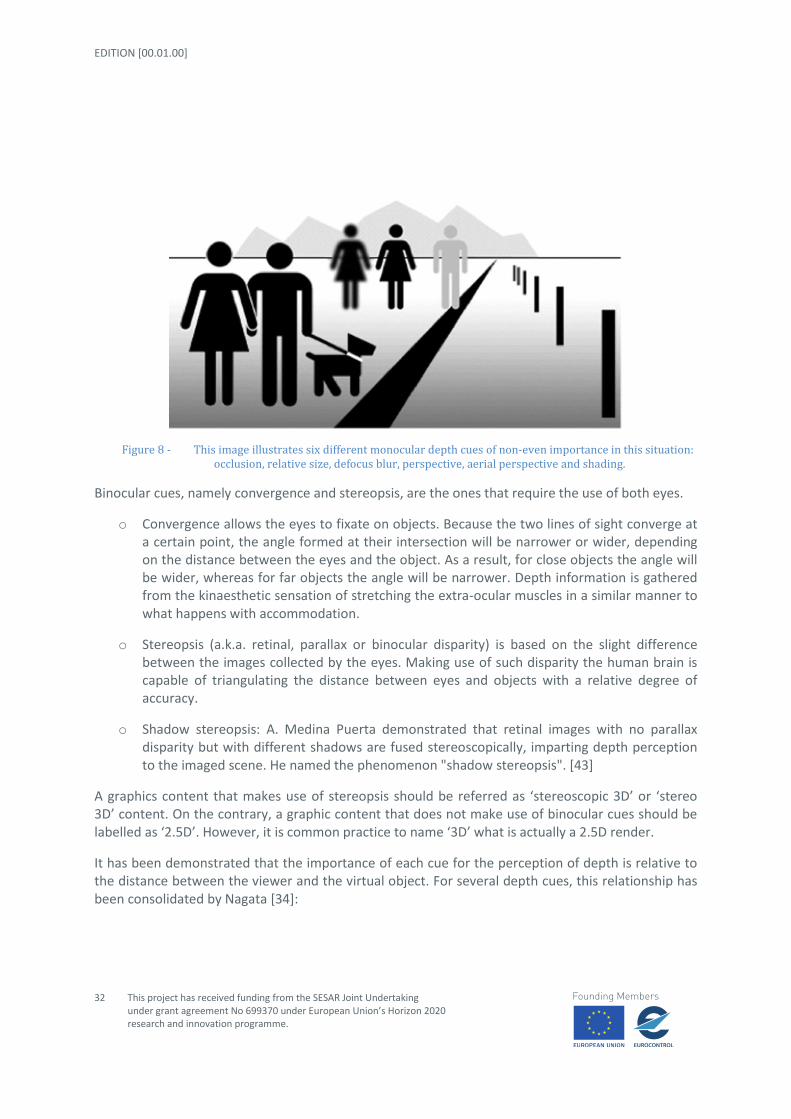
Figure 8 - This image illustrates six different monocular depth cues of non-even importance in this situation: occlusion, relative size, defocus blur, perspective, aerial perspective and shading.
Binocular cues, namely convergence and stereopsis, are the ones that require the use of both eyes.
o Convergence allows the eyes to fixate on objects. Because the two lines of sight converge at a certain point, the angle formed at their intersection will be narrower or wider, depending on the distance between the eyes and the object. As a result, for close objects the angle will be wider, whereas for far objects the angle will be narrower. Depth information is gathered from the kinaesthetic sensation of stretching the extra-ocular muscles in a similar manner to what happens with accommodation.
o Stereopsis (a.k.a. retinal, parallax or binocular disparity) is based on the slight difference between the images collected by the eyes. Making use of such disparity the human brain is capable of triangulating the distance between eyes and objects with a relative degree of accuracy.
o Shadow stereopsis: A. Medina Puerta demonstrated that retinal images with no parallax disparity but with different shadows are fused stereoscopically, imparting depth perception to the imaged scene. He named the phenomenon "shadow stereopsis". [43]
A graphics content that makes use of stereopsis should be referred as ‘stereoscopic 3D’ or ‘stereo 3D’ content. On the contrary, a graphic content that does not make use of binocular cues should be labelled as ‘2.5D’. However, it is common practice to name ‘3D’ what is actually a 2.5D render.
It has been demonstrated that the importance of each cue for the perception of depth is relative to the distance between the viewer and the virtual object. For several depth cues, this relationship has been consolidated by Nagata [34]:

STATE OF ART AND INITIAL CONCEPT REQUIREMENTS
This project has received funding from the SESAR Joint Undertaking under grant agreement No 699370 under European Union’s Horizon 2020 research and innovation programme.
33
Figure 9 - Lower perceivable depth contrast by means of a single depth cue as a function of the mean distance between the virtual object and the viewer (between 0.5 a 5000 meters).
In 1995, Cutting and Vishton ranked the importance of nine depth cues as a function of the distance between the object and the viewer. Their study distinguishes between three discreet depth intervals (that were already present in Nagata’s study): personal space (0,5 - 1,5 m), action space (1.5 – 30 m) and vista space (>30 m) [35].
Figure 10 - Ranking depth cues importance as a function of the depth space personal, action and vista intervals.

EDITION [00.01.00]
34
This project has received funding from the SESAR Joint Undertaking under grant agreement No 699370 under European Union’s Horizon 2020 research and innovation programme.
Although Cutting and Vishton’s chart is a good starting point, other studies do not agree on the importance of every single depth cue. For instance, in [36], Palmisano et al. suggest that binocular disparity has an impact on the vista space as well. This is somehow confirmed by very old studies on human sight [37], [38]. In the first study it is stated that human sight is capable of perceiving depth differences through very low binocular disparity. In the second study the authors conclude that binocular disparity is sufficient for distinguishing a point placed at infinity from a point placed up to 240 m from the user.
In any case, the importance of a depth cue providing information on the depth of an object is always relative to the presence of superior ranking depth cues for the same object. In other words, even if a depth cue provides some minor hint on the positioning such object, that cue is most likely to be overwritten by another having a greater importance in the designated space. For instance, accommodation, vergence and stereopsis can be easily overwritten by occlusion – i.e., even if these cues suggest that an object A is in front of an object B, but B is occluding A, the viewer will perceive B as being closer than A. However, it should not be taken for granted the contemporary presence of all depth cues. In this sense, a low level ranking cue may become of primary importance in absence of others, which might be exactly the case of the control tower at night or in low visibility conditions. During these periods some of the depth cues that the controller typically relies on are actually off because of the bad weather or because of the ‘light based’ visibility (e.g. 1, 2 and 5).
Most V/AR display systems provide some of the aforementioned depth cues to perform registration. However, in most cases there are depth cues missing, in conflict or out of control of the display system, which is one of the primary cause of eye-strain, fatigue and cybersickness. For instance, the vergence-accommodation conflict, is a well-known problem in the realm of virtual/augmented reality and stereoscopic displays in general. This conflict is due to the fact that the light rays coming from the virtual image source provide an accommodation depth cue that is rarely consistent with the vergence depth cue.
This forces the viewer’s brain to unnaturally adapt to conflicting cues, increases fusion time of binocular imagery and decreasing accuracy [39]. Also, it contributes to visual fatigue (asthenopia), especially during prolonged use [39]–[42], which, for some people, can even cause serious side-effects even after having used the device [43].
Figure 11 - A schematic of the vergence-accommodation conflict.
The problem is not as acute in some domains, such as 3D TV or cinema viewing, as it is in HMDs (as long as the content and displays both fit certain constraints). In 3D cinematography, where the light comes from a distant screen and the virtual objects are usually located at a great depth, stereo

STATE OF ART AND INITIAL CONCEPT REQUIREMENTS
This project has received funding from the SESAR Joint Undertaking under grant agreement No 699370 under European Union’s Horizon 2020 research and innovation programme.
35
parameters can be adjusted for each frame prior to viewing. For this reason, several methodologies have been developed on how to tailor the stereo content in order to make the viewer’s comfortable [44]–[47]. These are often based on a framework of constraints such as the one from Lambooij et. al in [41]. However, these constraints are hardly applicable to the context of real time VR [48]–[50] and AR applications [51], where content is dynamic and interactive, and must be displayed on the fly, without much post processing.
It should be noted that when the vergence-accommodation conflict occurs, vergence and accommodation are not the only two depth cues conflicting. This is because the accommodation depth cue is probably in conflict with other depth cues as well. However, it has been pointed out that oculomotor cues of consistent vergence and accommodation, which are related to retinal cues of blur and disparity, are critical to comfortable 3D viewing experience. Retinal blur is the actual visual cue driving the oculomotor response of accommodation, which adjusts the eye’s lens to focus on the desired depth, thus minimizing the blur. Likewise, retinal disparity is the visual cue that drives vergence. However, there is also a dual and parallel feedback loop between vergence and accommodation, and thus one becomes a secondary cue influencing the other [41], [42], [52]. In fact, Suryakumar et al. measured both vergence and accommodation at the same time during the viewing of stereoscopic imagery, concluding that accommodative response driven from disparity and resultant vergence is the same as the monocular response driven by retinal blur [53]. In a recent review of the topic, Bando et al. summarize some of the literature about this feedback mechanism within the human visual cortex [43].
The practice of providing the viewer with accommodation, vengeance and stereopsis depth cues that lead him, or her, into thinking that the object is placed at infinitum is commonly referred to as ‘collimation at optical infinity’. Optical infinity is a point in space from which the originating light rays can be considered as if they were parallel (collimated) when reaching the eye. Consequently, beyond optical infinity the eyes’ accommodation and vengeance adjustments are negligible. Based on a literature review, Peterson indicates that 6m can be considered as optical infinity [28]. Others suggest 9 meters [54].
Binocular disparity, which is the distance between a point in the left eye image and the very same point in the right eye image in screen space coordinates, increases with the distance between the viewer and the virtual point in an asymptotic way. If the projection screen is parallel to the segment connecting the viewer’s eyes (a.k.a. baseline), the asymptotic value is the viewer’s interpapillary distance (IPD)17, which is typically close to 6 cm . If the projection screen is not parallel to the segment connecting the viewer’s eyes the asymptotic value is the IPD multiplied by the cosine of the angle between the eye’s segment and the screen plane direction.
As panoramic environments only concern objects more than 30 m away, accommodation, vergence and binocular disparity of the augmented reality content should provide a visual stimulus which is consistent with the one of the real object. For vergence and accommodation this means that the
17 This is the distance between the two eyes, measured at the pupils.
EDITION [00.01.00]
36
This project has received funding from the SESAR Joint Undertaking under grant agreement No 699370 under European Union’s Horizon 2020 research and innovation programme.
virtual image focal plane should be positioned at least at optical infinity (i.e. at least six meters away from the user). In order to provide such visual stimulus by means of a transparent screen, either the screen itself must be moved to optical infinity or the emitted light must be collimated beyond that by means of optical lenses. The projection screen must also provide a binocular overlay since the (parallel) light rays from a single point will intersect the display surface at two different points before reaching the two eyes. However, if a common projection display surface is positioned in front of the user, it can actually be seen by both eyes. Therefore, the left eye image in the biocular display must be blocked for the right eye and vice versa. This is usually performed through different multiplexing techniques [55]. In binocular HMDs, each eye has its own image source [39].
Since binocular disparity is not effective in panoramic environments it has been suggested that it can be approximated with binocular disparity [28], [56]. Biocular disparity should not be confused with binocular disparity, where two slightly different images are rendered. When a biocular stimulus is used, each eye is provided with the same virtual image slightly translated left or right of a distance which is typically half of the IPD in order to place the virtual content at infinitum. However, it might not be particularly convenient to use such approximation in a multi-screen non planar V/AR environment, because this would increase the complexity of seams handling without truly eliminating the need for tracking the viewer’ eyes position with respect to the screen position and orientation.
For non-registered information such as wind direction and speed, temperature, QNH, etc., it might be convenient to place the AR content at optical infinity in order to minimize refocusing between far and close objects. However, this might depend on the controller’s tasks and on the layout of his/her working position. Since little research has been performed on this topic it is still unclear which solution would provide the less eye strain, fatigue and tunnelling effect – i.e. failure to switch between real and superimposed content or even between two synthetic contents (if placed at different depths). Much work has been done on collimation for cockpit HUDs, where some results show that collimation at optical infinity is better [57], while others suggest that the symbols should be displayed at 2 m from the observer [58].
As already mentioned, in order to achieve registration, one crucial factor is to take into account the coupling between the observer’s movements and the generation of the VR stimuli. Thus a major requirement for V/AR systems is to have accurate spatial data of the observed object, display and observer at all instances. This may be obtained by means of depth from stereo, infrared tracking or many others techniques (more about this in the next paragraph). Inaccurate measurements or latency in the tracking methodology lead to registration errors, which can seriously affect the system usability [28]. Tracking is a widely researched topic [59], [60] and will be further discuss in the next paragraphs. Eventually, the tracking process must result in the head/eyes coordinates being fed, in real time, to the rendering pipeline. Also, a custom rendering pipeline with a modified projection algorithm is needed to generate the binocular disparity stimuli that are not conflicting with the other depth cues [31].
This kind of behaviour can also be applied to virtual reality environments and synthetic vision systems that can benefit from the application of the fish-tank reality paradigm [61].
At smaller ranges the perspective from each eye is significantly different and the expense of generating two different visual channels for the computer-generated Imagery becomes worthwhile. On the contrary it would be difficult (and not particularly beneficial) to have an Enhanced Vision

STATE OF ART AND INITIAL CONCEPT REQUIREMENTS
This project has received funding from the SESAR Joint Undertaking under grant agreement No 699370 under European Union’s Horizon 2020 research and innovation programme.
37
System (EVS) that follows this rule, given that the camera’s optical unit is fixed in space with respect to the parent body (could be an aircraft fuselage or a control tower structure). In any case, for such systems, it is still imperative that the augmented reality content matches the one of the video stream by means of precise calculation of the camera position and rotation with respect to the surrounding environment (which can be derived from the orientation between the camera and the parent body object).
3.3 User presence and eye tracking technologies
The technological solutions used for the problem of determining where the user is physically located and where they are looking depend upon if they are using head mounted devices, hand-held devices, or, spatial devices. These different solutions are detailed below.
3.3.1 Head Mounted
Location of user
To determine the location of the user with sufficient precision, the cameras on the head mounted device could use the location of known fixed points of reference. When initialized, the HMD camera could be locked on to a defined location within the tower. Movement within the tower is then determined.
Position of user's head
The most used filter to estimate head motion is the extended Kalman filter (EKF)[25]. This filter is based upon the principle of linearizing the measurements and evolution models using Taylor series expansions. The series approximations in the EKF algorithm can, however, lead to poor representations of the non-linear functions and probability distributions of interest. Besides, when dealing with non-linear models (like head motion), the EKF method may lead to a non optimal solution. A classical particle filter Bayesian bootstrap may be more appropriate to predict head motion.
Alternately, the HMD may be equipped with inertial sensors for six-degree freedom of movement tracking, i.e., head movement tracking. These devices or sensors are available, for example, from Chronos Vision GmbH, Berlin, Germany and ISCAN, Woburn, Mass.
Direction of user's gaze.
For HMDs a system that can be used is one with a forward-facing scene camera that records the participant’s field of view. The lenses are made of infrared reflective glass, so an infrared light can be reflected off the retina and through the pupil to be detected by the eye tracking camera. The position of the pupil reflection is then registered with respect to the scene camera, giving an (x, y) coordinate for where the eye gaze is directed at any given time. In addition to the glasses and support processor, the system makes use of an infrared (IR) marker system. The IR markers are not worn, but are placed in the environment in which the subjects will be working. The IR markers

EDITION [00.01.00]
38
This project has received funding from the SESAR Joint Undertaking under grant agreement No 699370 under European Union’s Horizon 2020 research and innovation programme.
provide stable landmarks in the scene so that the system can compute where the eye gaze falls in the world that is viewed. The markers are small, highly portable, and can be installed and removed in minutes. IR markers enable the eye tracking system to achieve registration of the eye data onto multiple planes of the visual scene[26].
Figure 12 - This figure depicts one embodiment of a portion of an HMD in which gaze vectors extending to a near point of gaze are used for aligning an inter-pupillary distance (IPD).

STATE OF ART AND INITIAL CONCEPT REQUIREMENTS
This project has received funding from the SESAR Joint Undertaking under grant agreement No 699370 under European Union’s Horizon 2020 research and innovation programme.
39
Figure 13 - This figure depicts one embodiment of a portion of an HMD in which gaze vectors extending to a far point of gaze are used for aligning an inter-pupillary distance (IPD), the distance between the user's pupils.
The eyepiece may be able to determine where the user is gazing, or the motion of the user's eye, by tracking the eye through reflected light off the user's eye. This information may then be used to help correlate the user's line of sight with respect to the projected image, a camera view, the external environment, and the like, and used in control techniques as described herein. For instance, the user may gaze at a location on the projected image and make a selection, such as with an external remote control or with some detected eye movement (e.g. blinking). In an example of this technique transmitted light 1508E, such as infrared light, may be reflected 1510E from the eye 1504E and sensed at the optical display 502 (e.g. with a camera or other optical sensor). The information may then be analyzed to extract eye rotation from changes in reflections.
An eye tracking facility may use the corneal reflection and the centre of the pupil as features to track over time; use reflections from the front of the cornea and the back of the lens as features to track; image features from inside the eye, such as the retinal blood vessels, and follow these features as the eye rotates; and the like.
Alternatively, the eyepiece may use other techniques to track the motions of the eye, such as with components surrounding the eye, mounted in contact lenses on the eye, and the like. For instance, a

EDITION [00.01.00]
40
This project has received funding from the SESAR Joint Undertaking under grant agreement No 699370 under European Union’s Horizon 2020 research and innovation programme.
special contact lens may be provided to the user with an embedded optical component, such as a mirror, magnetic field sensor, and the like, for measuring the motion of the eye.
Electric potentials can be measured and monitored with electrodes placed around the eyes, utilizing the steady electric potential field from the eye as a dipole, such as with its positive pole at the cornea and its negative pole at the retina. In this instance, the electric signal may be derived using contact electrodes placed on the skin around the eye, on the frame of the eyepiece, and the like. If the eye moves from the centre position towards the periphery, the retina approaches one electrode while the cornea approaches the opposing one. This change in the orientation of the dipole and consequently the electric potential field results in a change in the measured signal. By analyzing these changes eye movement may be tracked.
The glasses may be equipped with eye tracking devices for tracking movement of the user's eye, or preferably both eyes. Retinal scanners are also available for tracking eye movement. Retinal scanners may also be mounted in the augmented reality glasses and are available from a variety of companies, such as Tobii, Stockholm, Sweden, and SMI, Teltow, Germany, and ISCAN.
3.3.2 Spatial devices
Location of user
Determining the location of the user would be accomplished through the use of a fixed camera co-located within the control tower aimed at the controller working position.
Fig. 14 illustrates an example embodiment of the capture device that may be used in the target recognition, analysis, and tracking system. The capture device may be configured to capture video with depth information including a depth image that provides depth values via any suitable technique including, for example, time-of-flight, structured light, stereo imaging, or the like.

STATE OF ART AND INITIAL CONCEPT REQUIREMENTS
This project has received funding from the SESAR Joint Undertaking under grant agreement No 699370 under European Union’s Horizon 2020 research and innovation programme.
41
Figure 14 - Example embodiment of the capture device.
The image camera component may include an IR light component, a three-dimensional (3-D) camera and an RGB camera that may be used to capture the depth image of a scene.
In a time-of-flight analysis, the IR light component of the capture device may emit an infrared light onto the scene and may then use sensors (not shown) to detect the backscattered light from the surface of one or more targets and objects in the scene using, for example, the 3-D camera and/or the RGB camera . In some embodiments, pulsed infrared light may be used such that the time between an outgoing light pulse and a corresponding incoming light pulse may be measured and used to determine a physical distance from the capture device to a particular location on the targets or objects in the scene. Additionally, in other example embodiments, the phase of the outgoing light wave may be compared to the phase of the incoming light wave to determine a phase shift. The phase shift may then be used to determine a physical distance from the capture device to a particular location on the targets or objects. According to another example embodiment, time-of-flight analysis may be used to indirectly determine a physical distance from the capture device to a particular location on the targets or objects by analyzing the intensity of the reflected beam of light over time via various techniques including, for example, shuttered light pulse imaging.
Structured light can be used to capture depth information. In such an analysis, patterned light (i.e., light displayed as a known pattern such as grid pattern or a stripe pattern) may be projected onto the scene via, for example, the IR light component. Upon striking the surface of one or more targets or objects in the scene, the pattern may become deformed in response. Such a deformation of the pattern may be captured by, for example, the 3-D camera and/or the RGB camera and may then be
Processor
Memory
Capture Device
Camera Component
IR
3D
RGB
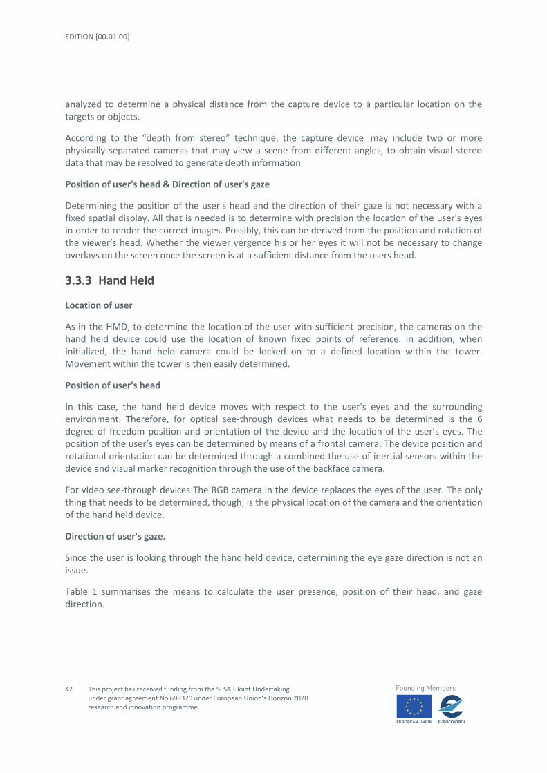
EDITION [00.01.00]
42
This project has received funding from the SESAR Joint Undertaking under grant agreement No 699370 under European Union’s Horizon 2020 research and innovation programme.
analyzed to determine a physical distance from the capture device to a particular location on the targets or objects.
According to the “depth from stereo” technique, the capture device may include two or more physically separated cameras that may view a scene from different angles, to obtain visual stereo data that may be resolved to generate depth information
Position of user's head & Direction of user's gaze
Determining the position of the user's head and the direction of their gaze is not necessary with a fixed spatial display. All that is needed is to determine with precision the location of the user's eyes in order to render the correct images. Possibly, this can be derived from the position and rotation of the viewer’s head. Whether the viewer vergence his or her eyes it will not be necessary to change overlays on the screen once the screen is at a sufficient distance from the users head.
3.3.3 Hand Held
Location of user
As in the HMD, to determine the location of the user with sufficient precision, the cameras on the hand held device could use the location of known fixed points of reference. In addition, when initialized, the hand held camera could be locked on to a defined location within the tower. Movement within the tower is then easily determined.
Position of user's head
In this case, the hand held device moves with respect to the user's eyes and the surrounding environment. Therefore, for optical see-through devices what needs to be determined is the 6 degree of freedom position and orientation of the device and the location of the user’s eyes. The position of the user’s eyes can be determined by means of a frontal camera. The device position and rotational orientation can be determined through a combined the use of inertial sensors within the device and visual marker recognition through the use of the backface camera.
For video see-through devices The RGB camera in the device replaces the eyes of the user. The only thing that needs to be determined, though, is the physical location of the camera and the orientation of the hand held device.
Direction of user's gaze.
Since the user is looking through the hand held device, determining the eye gaze direction is not an issue.
Table 1 summarises the means to calculate the user presence, position of their head, and gaze direction.
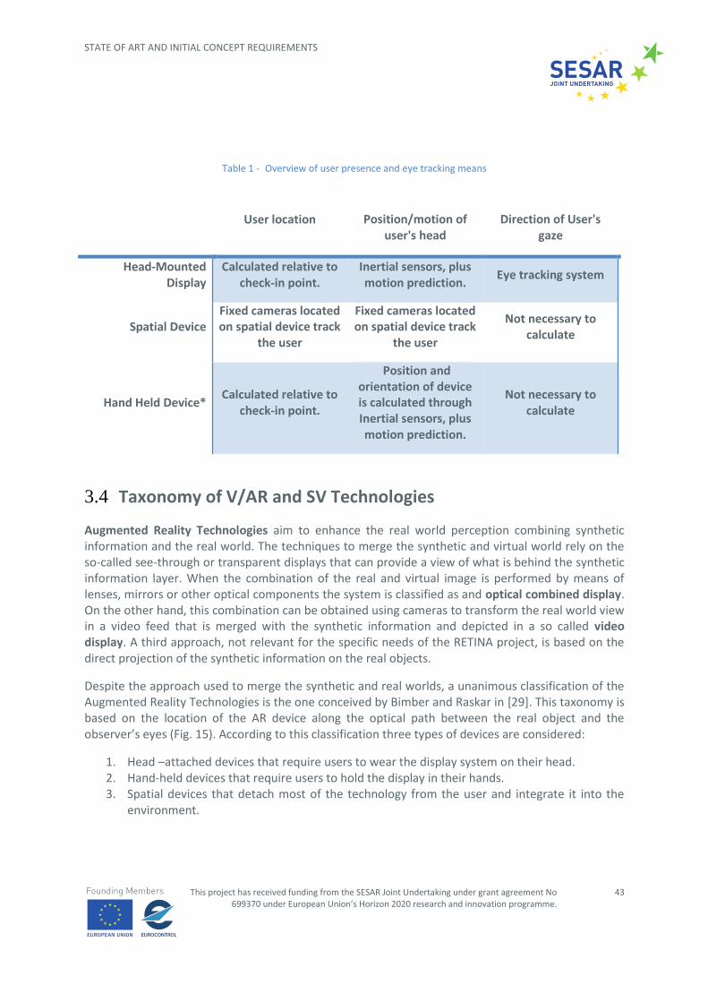
STATE OF ART AND INITIAL CONCEPT REQUIREMENTS
This project has received funding from the SESAR Joint Undertaking under grant agreement No 699370 under European Union’s Horizon 2020 research and innovation programme.
43
Table 1 - Overview of user presence and eye tracking means
User location Position/motion of user's head
Direction of User's gaze
Head-Mounted Display
Calculated relative to check-in point.
Inertial sensors, plus motion prediction.
Eye tracking system
Spatial Device Fixed cameras located on spatial device track
the user
Fixed cameras located on spatial device track
the user
Not necessary to calculate
Hand Held Device* Calculated relative to
check-in point.
Position and orientation of device is calculated through Inertial sensors, plus motion prediction.
Not necessary to calculate
3.4 Taxonomy of V/AR and SV Technologies
Augmented Reality Technologies aim to enhance the real world perception combining synthetic information and the real world. The techniques to merge the synthetic and virtual world rely on the so-called see-through or transparent displays that can provide a view of what is behind the synthetic information layer. When the combination of the real and virtual image is performed by means of lenses, mirrors or other optical components the system is classified as and optical combined display. On the other hand, this combination can be obtained using cameras to transform the real world view in a video feed that is merged with the synthetic information and depicted in a so called video display. A third approach, not relevant for the specific needs of the RETINA project, is based on the direct projection of the synthetic information on the real objects.
Despite the approach used to merge the synthetic and real worlds, a unanimous classification of the Augmented Reality Technologies is the one conceived by Bimber and Raskar in [29]. This taxonomy is based on the location of the AR device along the optical path between the real object and the observer’s eyes (Fig. 15). According to this classification three types of devices are considered:
1. Head –attached devices that require users to wear the display system on their head. 2. Hand-held devices that require users to hold the display in their hands. 3. Spatial devices that detach most of the technology from the user and integrate it into the
environment.

EDITION [00.01.00]
44
This project has received funding from the SESAR Joint Undertaking under grant agreement No 699370 under European Union’s Horizon 2020 research and innovation programme.
Figure 15 - Classification of the Augmented Reality Technologies by Bimber and Raskar [29]
Figure 16 - Head-attached devices taxonomy
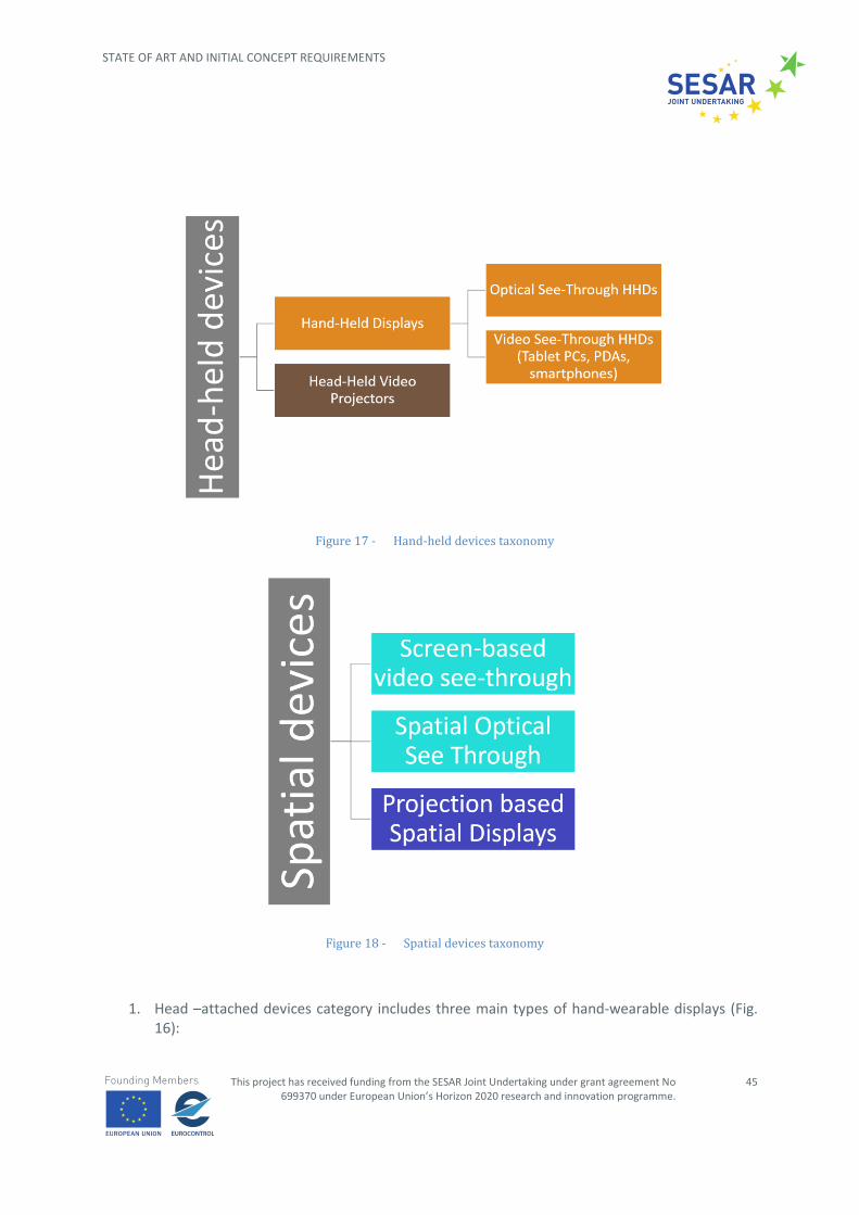
STATE OF ART AND INITIAL CONCEPT REQUIREMENTS
This project has received funding from the SESAR Joint Undertaking under grant agreement No 699370 under European Union’s Horizon 2020 research and innovation programme.
45
Figure 17 - Hand-held devices taxonomy
Figure 18 - Spatial devices taxonomy
1. Head –attached devices category includes three main types of hand-wearable displays (Fig. 16):
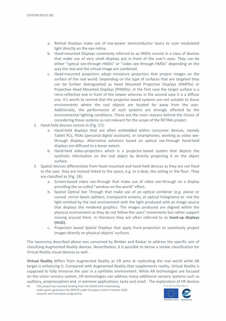
EDITION [00.01.00]
46
This project has received funding from the SESAR Joint Undertaking under grant agreement No 699370 under European Union’s Horizon 2020 research and innovation programme.
a. Retinal Displays make use of low-power semiconductor lasers to scan modulated light directly on the eye retina.
b. Head-mounted Displays commonly referred to as HMDs consist in a class of devices that make use of very small displays put in front of the user’s eyes. They can be either “optical see-through HMDs” or “video see-through HMDs” depending on the way the real and the virtual image are combined.
c. Head-mounted projectors adopt miniature projectors that project images on the surface of the real world. Depending on the type of surfaces that are targeted they can be further distinguished as Head Mounted Projective Displays (HMPDs) or Projective Head Mounted Displays (PHMDs). In the first case the target surface is a retro-reflective one in front of the viewer whereas in the second case it is a diffuse one. It’s worth to remind that the projector based systems are not suitable to those environments where the real objects are located far away from the user. Additionally, the performance of such systems are strongly affected by the environmental lighting conditions. These are the main reasons behind the choice of considering those systems as not relevant for the scope of the RETINA project.
2. Hand-held devices consist in (Fig. 17): a. Hand-held displays that are often embedded within consumer devices, namely
Tablet PCs, PDAs (personal digital assistant), or smartphones, working as video see-through displays. Alternative solutions based on optical see-through hand-held displays are diffused to a lesser extent.
b. Hand-held video-projectors which is a projector-based system that depicts the synthetic information on the real object by directly projecting it on the object surface.
3. Spatial devices differentiate from head-mounted and hand-held devices as they are not fixed to the user, they are instead linked to the space, e.g. to a desk, the ceiling or the floor. They are classified as (Fig. 18):
a. Screen-based video see-through that make use of video see-through on a display providing the so-called “window on the world” effect.
b. Spatial Optical See Through that make use of an optical combiner (e.g. planar or curved mirror beam splitters, transparent screens, or optical holograms) to mix the light emitted by the real environment with the light produced with an image source that displays the rendered graphics. The images produced are aligned within the physical environment as they do not follow the users’ movements but rather support moving around them. In literature they are often referred to as head-up displays (HUD).
c. Projection based Spatial Displays that apply front-projection to seamlessly project images directly on physical objects' surfaces.
The taxonomy described above was conceived by Bimber and Raskar to address the specific aim of classifying Augmented Reality devices. Nevertheless, it is possible to derive a similar classification for Virtual Reality visual devices as well.
Virtual Reality differs from Augmented Reality as VR aims at replicating the real world while AR target is enhancing it. Compared with Augmented Reality that supplements reality, Virtual Reality is supposed to fully immerse the user in a synthetic environment. While AR technologies are focused on the vision sensory system, VR technologies can address many additional sensory systems such as auditory, proprioception and, in extreme applications, taste and smell. The exploration of VR devices

STATE OF ART AND INITIAL CONCEPT REQUIREMENTS
This project has received funding from the SESAR Joint Undertaking under grant agreement No 699370 under European Union’s Horizon 2020 research and innovation programme.
47
addressing other sensory systems but vision and hearing is out of the scope of this document as the ATC tasks rely on visual and auditory perception of the environment. Nevertheless, a comprehensive taxonomy for existing VR technologies can be found in [30] that classifies the most recent input/output VR commercial devices.
Synthetic Vision devices are application-oriented systems where data coming from different sources is filtered and fused providing the pilot with a comprehensive view of the flying environment in poor visibility conditions. Based on the type of data that is considered to reconstruct the external view and the mean used for visualization, Synthetic Vision devices can be classified into three main categories:
1. Enhanced Vision Systems (EVS) and Enhanced Flight Vision Systems (EFVS) 2. Synthetic Vision Systems (SVS) 3. Combined Vision Systems (CVS) and Verified Combined Vision Systems (VCVS)
An Enhanced Vision System (EVS) (or Enhanced Flight Vision System) is an electronic means to provide a display of the external scene by use of an imaging sensor, such as a Forward-Looking InfraRed (FLIR) or millimeter wave radar. It provides pilots with a clear live video image of the world that s/he could not otherwise see at night, and in poor visibility. As far as technology is concerned, the main difference between EVS and EFVS consists in the alignment of additional information with the external view and the use of head-up displays to show them that are essential features for EFVS, as shown in Figure 19.
Figure 19 - EVS vs EFVS
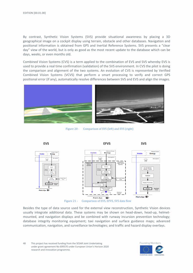
EDITION [00.01.00]
48
This project has received funding from the SESAR Joint Undertaking under grant agreement No 699370 under European Union’s Horizon 2020 research and innovation programme.
By contrast, Synthetic Vision Systems (SVS) provide situational awareness by placing a 3D geographical image on a cockpit display using terrain, obstacle and other databases. Navigation and positional information is obtained from GPS and Inertial Reference Systems. SVS presents a “clear day” view of the world, but is only as good as the most recent update to the database which can be days, weeks, or even months old.
Combined Vision Systems (CVS) is a term applied to the combination of EVS and SVS whereby EVS is used to provide a real time confirmation (validation) of the SVS environment. In CVS the pilot is doing the comparison and alignment of the two systems. An evolution of CVS is represented by Verified Combined Vision Systems (VCVS) that perform a smart processing to verify and correct GPS positional error (if any), automatically resolve differences between SVS and EVS and align the images.
Figure 20 - Comparison of SVS (left) and EVS (right)
EVS EFVS SVS
Figure 21 - Comparison of EVS, EFVS, SVS data flow
Besides the type of data source used for the external view reconstruction, Synthetic Vision devices usually integrate additional data. These systems may be shown on head-down, head-up, helmet-mounted, and navigation displays and be combined with runway incursion prevention technology; database integrity monitoring equipment; taxi navigation and surface guidance maps; advanced communication, navigation, and surveillance technologies; and traffic and hazard display overlays.

STATE OF ART AND INITIAL CONCEPT REQUIREMENTS
This project has received funding from the SESAR Joint Undertaking under grant agreement No 699370 under European Union’s Horizon 2020 research and innovation programme.
49
3.5 Technology #1 – Head Mounted Displays (both VR and See-Through)
A head-mounted display, often referred as helmet-mounted display in military and aviation applications, both abbreviated HMD, is a single-user V/AR piece of equipment worn on the head or as part of a helmet that provides symbolic or pictorial information by introducing into the user's visual pathway a virtual image [62]. Helmet-Mounted Sight (HMS) is another term often used referring to an HMD that provides only a simple targeting gunsight.
HMDs differ in whether they can display just a computer generated image, show live images from the real world or a combination of both. In the first case, they can be referred as a Virtual Reality Headset (VRH), which are typically opaque and only provide an immersive visual of the virtual environment. In the latter case, they should be referred as a See-Through Head Mounted Displays (ST-HMDs). Amongst ST-HMDs two further categories can be distinguished: video see-through and optical see-through systems. Video see-through displays capture video of the real world and digitally combine it with synthetic imagery before re-displaying it to the user. This can be considered a form of mixed reality. Optical see-through systems let through or optically propagate light rays from the real world and use semi-transparent combiners (a.k.a. beam-splitters) to combine them with virtual imagery. Refer to Fig.22 for a comparison of these two methods.
Figure 22 - Basic classification of HMDs types
HM
Ds
See-through
Video see-through
Optical see-throughVirtual Reality
Headsets

EDITION [00.01.00]
50
This project has received funding from the SESAR Joint Undertaking under grant agreement No 699370 under European Union’s Horizon 2020 research and innovation programme.
In its simplest form, a HMD consists of an image source and accommodative optics in head mount.
Figure 23 - A schematic of the first Oculus Rift VHR
However, modern designs have long made this definition over simplistic. In order to understand the more complicated layouts it is useful to classify HMDs based on the type of visual stimuli they
provide, i.e. (a) monocular, (b) biocular or (c) binocular, which is sometimes referred as ‘ocularity’.
(a) Monocular HMDs only provide a single image to a single eye. This is usually the lightest, least expensive, and simplest HMD type. For this reasons, most of current military HMD systems are monocular. A few examples are provided by Melzer in [54]. This particular design often comes associated with an asymmetric centre of gravity and some issues dealing with focus, eye dominance, binocular rivalry, and ocular-motor instability [63], [64].
(b) Biocular HMDs provide the same image for both eyes (either shared or duplicated). The biocular approach is more complex than the monocular design, but eliminates the ocular-motor instability issues associated with monocular displays. In the end, viewing imagery with two eyes has been shown to yield improvements in detection as well as providing a more comfortable viewing experience [65], [66]. The primary disadvantage of the biocular design is that the image source is usually located in the forehead region, making it more difficult to package. Biocular displays use one or two identical image sources paired with a single set or double set of optics. For this reason, they tend to be larger and heavier than monocular systems, which use a single image source and a single set of optics. Finally, binocular HMDs are subject to strict alignment, focus and calibration requirements.

STATE OF ART AND INITIAL CONCEPT REQUIREMENTS
This project has received funding from the SESAR Joint Undertaking under grant agreement No 699370 under European Union’s Horizon 2020 research and innovation programme.
51
(c) Binocular HMDs present two slightly different images to the right and left eyes (as in real sight). This is the most complex, expensive, and heaviest of all three options, but one which has all the advantages of a two-eyed system with the added benefit of providing partial binocular overlap (which enlarges the horizontal field of view) and binocular disparity. A binocular HMD is subject to the same alignment, focus and calibration requirements as the biocular design. The simple magnifier or the freeform waveguide designs are two examples of fixed Stereoscopic HMDs. A few examples of military grade Binocular HMDs can be found in (James E. Melzer 2001). For consumer grade devices and at the time being, the reader can refer to the Microsoft HoloLens and the DAQRI Smart Helmet for see-though HMDs as well as to the Oculus Rift and the HTC Vive for VRHs.
shows a comparison between the benefits and drawbacks of monocular, biocular and binocular HMDs.
Table 2 - Comparison between the benefits and drawbacks of monocular, biocular and binocular HMDs.
CONFIGURATION ADVANTAGES DRAWBACKS
MONOCULAR
(single image viewed by
single eye)
Lightweight
Compact
Simple calibration
Cheap
Asymmetrical centre of
gravity
Ocular motor instability
Eye dominance
Focus issues
BIOCULAR
(single image viewed by
both eyes)
Symmetrical centre of
gravity
Cheap
Complex calibration
Bulky
Heavy
BINOCULAR
(double image viewed by
both eyes)
Symmetrical centre of
gravity
Larger FOV
Better depth perception
Complex calibration
Bulky
Heavy
Expensive
The HMD itself is often part of a larger system which includes an image generator (i.e. an integrated or separate computer), a head tracker (might be synthesized from multiple sources, such as three-axis gyros, accelerometers and magnetometers), which can be embedded in the headgear, video and IR cameras, depth sensors, audio input and several other input devices. Some HMD vendors offer on-
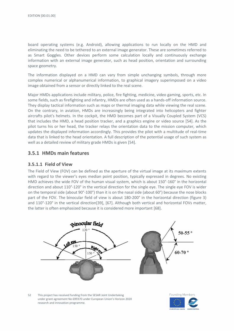
EDITION [00.01.00]
52
This project has received funding from the SESAR Joint Undertaking under grant agreement No 699370 under European Union’s Horizon 2020 research and innovation programme.
board operating systems (e.g. Android), allowing applications to run locally on the HMD and eliminating the need to be tethered to an external image generator. These are sometimes referred to as Smart Goggles. Other devices perform some calculation locally and continuously exchange information with an external image generator, such as head position, orientation and surrounding space geometry.
The information displayed on a HMD can vary from simple unchanging symbols, through more complex numerical or alphanumerical information, to graphical imagery superimposed on a video image obtained from a sensor or directly linked to the real scene.
Major HMDs applications include military, police, fire fighting, medicine, video gaming, sports, etc. In some fields, such as firefighting and infantry, HMDs are often used as a hands-off information source. They display tactical information such as maps or thermal imaging data while viewing the real scene. On the contrary, in aviation, HMDs are increasingly being integrated into helicopters and fighter aircrafts pilot's helmets. In the cockpit, the HMD becomes part of a Visually Coupled System (VCS) that includes the HMD, a head position tracker, and a graphics engine or video source [54]. As the pilot turns his or her head, the tracker relays the orientation data to the mission computer, which updates the displayed information accordingly. This provides the pilot with a multitude of real-time data that is linked to the head orientation. A full description of the potential usage of such system as well as a detailed review of military grade HMDs is given [54].
3.5.1 HMDs main features
3.5.1.1 Field of View
The Field of View (FOV) can be defined as the aperture of the virtual image at its maximum extents with regard to the viewer’s eyes median point position, typically expressed in degrees. No existing HMD achieves the wide FOV of the human visual system, which is about 150°-160° in the horizontal direction and about 110°-120° in the vertical direction for the single eye. The single eye FOV is wider on the temporal side (about 90°-100°) than it is on the nasal side (about 60°) because the nose blocks part of the FOV. The binocular field of view is about 180-200° in the horizontal direction (figure 3) and 110°-120° in the vertical direction[39], [67]. Although both vertical and horizontal FOVs matter, the latter is often emphasized because it is considered more important [68].

STATE OF ART AND INITIAL CONCEPT REQUIREMENTS
This project has received funding from the SESAR Joint Undertaking under grant agreement No 699370 under European Union’s Horizon 2020 research and innovation programme.
53
Figure 24 - Graphical representation of the human FOV
Most people do not have a good feel for what a particular quoted FOV would look like; therefore manufacturers may specify a virtual screen size, viewed from a specified distance, in order to describe their devices’ FOV.
When asked about HMD requirements, users will typically want more of FOV and resolution. Old generation consumer-level HMDs typically offered a FOV of about 30-40° whereas professional HMDs or new generation HMDs offer a field of view up to 150°. However, optical ST-HUDs are typically more FOV limited than video see-through HMDs and VRH. Both intuition and evidence lead to the conclusion that decreasing the FOV size results in a performance loss and compromises the viewer’s sense of immersion and situational awareness. Thus, a wide FOV is highly desirable (but not always necessary). However, for a fixed display, an HMD cannot both simultaneously increase spatial resolution and FOV because these attributes are linked together by the focal length of the collimating optics. Also, increasing the FOV by increasing optical magnification usually provokes some weight increase due to the use of larger optical elements [69].
3.5.1.2 Resolution
HMDs producers usually mention either the total number of pixels or the number of pixels per degree. Listing the total number of pixels (e.g. 1920×1080 pixels per eye) is borrowed from the practice of providing computer monitors specifications. However, the pixel density, usually specified in pixels per degree or in arc-minutes per pixel, is also used to specify visual acuity. 60 pixels/° is usually referred to as eye limiting resolution in the central part of the fovea, above which increased resolution is not noticed by people with normal vision. HMDs typically offer 10 to 20 pixels/°, though advances in micro-displays may help increase this number. While more visual acuity is desirable, FOV and visual acuity (VA) in an HMD are linked by the relationships:
𝑉𝐴[𝑝𝑖𝑥𝑒𝑙 °⁄ ] =𝑉[𝑝𝑖𝑥𝑒𝑙]
𝐹𝑂𝑉[°]
thus, given a certain image source increasing the FOV also reduces the VA
𝐹𝑂𝑉[°] = tan−1 (𝐻[𝑚]
𝐹[𝑚])
The focal length of the collimating lens (F) determines the relationship between H, the size of the image source and the field of view. Some vendors employ multiple micro-displays to increase total resolution and field of view.
3.5.1.3 Binocular Overlap
Binocular overlap measures the horizontal field of view that is common to both eyes. This allows the device to create a ‘stereo zone’ where the binocular disparity is actually provided. Overlap is usually specified in terms of degrees or as a percentage indicating how much of the visual field of each eye is common to the other eye.
EDITION [00.01.00]
54
This project has received funding from the SESAR Joint Undertaking under grant agreement No 699370 under European Union’s Horizon 2020 research and innovation programme.
3.5.1.4 Weight
It is highly desirable that the device weights only as little as possible in order to allow for long usage sessions. Also the device should be well balances and possibly adjustable to the user’s head geometry. Many reports suggest that past generations devices were very far from being ergonomic.
3.5.1.5 Size
Sometimes, even if the weight of the device is acceptable, its size can still be an issue. Thus the design should be as compact as possible except for those applications where the HMD is coupled with a safety or military helmet and some parts of it can be actually consolidated into that.
3.5.1.6 Power Consumption
Is the device plugged to a power source? Does it need wired connection for video stream between the optical compartment and the external image generator? If so, power consumption is not a main issue. On the contrary, if the device is completely wireless, which allows for the maximum movement flexibility, a careful design of the image source, sensory components and computing components is needed in order not to carry around too much battery weight. For instance, some image sources, such as CRTs (Cathode Ray Tubes) displays and AMELs (Active Matrix Electroluminescent) displays have considerable power consumption.
3.5.1.7 Addressability
Raster scan displays are considered infinitely addressable because the imagery is drawn in calligraphic fashion. Pixilated devices such as LCDs (Liquid Crystal Displays), AMELs (Active Matrix Electroluminescent) and OLEDs (Organic Light Emitting Diode) are considered finite addressable displays because the pixel location is fixed. This limits their ability to compensate for optical distortions induced by the optical compartment.
3.5.1.8 Aspect Ratio
Most miniature CRTs (Cathode Ray Tube) have a circular format, while most of the solid-state pixilated devices such as LCDs and AMELs and OLEDs have a rectangular form factor. For instance, Full HD resolution displays have a 16:9 aspect ratio. This parameter contributes to determine the field of view of the display and the binocular overlap.
3.5.1.9 Luminance and Contrast
It is important that the image source is capable of providing a display luminance and contrast that is compatible with the ambient backgrounds brightness. Literature proves that text and symbols readability is a major issue in see-through augmented reality displays, and is also influenced by colours and styles [70], [71].
3.5.1.10 Colour
Is the image source capable of producing colour imagery? Color-coding has proven to be useful in many situations, however a limited colour spectrum might be sufficient for some AR applications.
3.5.1.11 Image sources
There are four main categories of image sources (a) transmissive displays, (b) reflective displays (c) emissive displays and (d) scanning displays.

STATE OF ART AND INITIAL CONCEPT REQUIREMENTS
This project has received funding from the SESAR Joint Undertaking under grant agreement No 699370 under European Union’s Horizon 2020 research and innovation programme.
55
The non-emissive technologies, namely (a) and (b), modulate a separate illumination on a pixel-by-pixel basis to create the desired imagery.
(a) Transmissive displays use a backlight to illuminate an active matrix of pixels. A modulated electric field controls the transmission of the backlight through the individual pixels (or RGB subpixels). The most common application of such technology is the one of Active Matrix Liquid Crystal Displays (or simply LCD)
(b) Reflective displays use a backlight to illuminate an active matrix of pixels or micro-mirrors. A modulated electric field controls the reflection of the frontlight against the individual pixels, RGB subpixels or micro-mirrors. Examples of reflective displays are:
Digital Light Processing (DLP) displays or projectors. This technology uses tiny mirrors, one for each pixel, to reflect the (coloured) frontlight either away or into the optical path. Rapidly toggling the mirror between these two orientations produces grayscales, controlled by the ratio of on-time to off-time. Because the driving electronics is placed under the micro-mirrors instead of at their side, DLP technology typically results in a good fill factor, which leads to a reduced screen-door effect.
Reflective Liquid Crystal on Silicon Displays (LCoS) displays. This is a hybrid technology that combines the idea of LCD and DLP. In LCoS, liquid crystals are applied to a reflective mirror substrate. As the liquid crystals open and close, the light is either reflected from the mirror below, or scattered. This modulates the light and creates the image.
Emissive and scanning technologies, namely (c) and (d) devices emit light without the need for additional illumination. (c) Emissive displays are based on an active pixel matrix where individual pixels or RGB subpixels are turned on/of or partially on. Examples of emissive displays are:
Active Matrix Electroluminescent (AMEL) displays. A thin-film layer of luminescent phosphor is sandwiched between two electrodes, one transparent, in a pixilated array. The subpixels are digitally addressed using high-frequency pulses to achieve grayscale. Recent improvements use a quasi-analog signal to achieve greater grayscale range and improved luminance. These are compact and very rugged devices [72].
Vacuum Fluorescent Displays (VFDs). VFDs use a vacuum package containing phosphors that are excited by a series of filaments. Currently they are only used as alphanumeric, low-resolution displays. However, their capabilities could be expanded in order to accommodate higher resolution images.
Organic Light Emitting Diodes (OLED) displays. A thin layer of organic semiconductor material is placed between two electrodes emitting visible light in response to an electric current. It has been demonstrated that this technology can be used to produce very thin, curved and flexible displays.

EDITION [00.01.00]
56
This project has received funding from the SESAR Joint Undertaking under grant agreement No 699370 under European Union’s Horizon 2020 research and innovation programme.
(d) Scanning displays do not rely on a pixel matrix in order to spatially build up the image, but rather on a raster scan path that creates the image in calligraphic fashion. In this sense scanning technologies are both time and space multiplexed. Examples of scanning displays are:
Retinal Scanning Display (RSD). A light beam (such as a laser) or a line of point sources (such as LEDs) is modulated in space and time using resonance scanners or opto-acoustic modulators to produce imagery. [73], [74]
Cathode Ray Tube (CRT) displays. These are vacuum tubes with one or more electron-guns at one end and a RGB phosphor screen at the other. The beams from the electron guns are modulated by deflection grids and directed onto the screen. The incident electrons excite the phosphor, emitting visible light [75].
Figure 25 - Classification of common HMDs’ image sources
In the past many HMDs used to have CRT image sources. As of this writing, most HMDs use either LCDs or OLED displays though there is a strong interest in developing new technologies that can further reduce the weight and size of the image source generators.
IMA
GE
SO
UR
CE
S
Non emissive
Transmissive LCD
Reflective
DLP
LCoS
Emissive
AMEL
VFD
OLED
Scanning
RSD
CRT

STATE OF ART AND INITIAL CONCEPT REQUIREMENTS
This project has received funding from the SESAR Joint Undertaking under grant agreement No 699370 under European Union’s Horizon 2020 research and innovation programme.
57
Table 3 - Benefits and drawbacks of common HMDs’ image sources
CATEGORY TRANSMISSIVE REFLECTIVE SELF-EMISSIVE SCANNING
BENEFITS Largely available
on the market
Fairly good
image quality.
Cheap
Good contrast
Fair price
Good fill factor
(DLP)
Low power
consumption
Flexible
Thin
Lightweight
Good response
time
Good luminance
and saturation
Ruggerized
design possible
Easy distortion
handling
DRAWBACKS Power
consuming
Limited response
time
Heat generation
Power
consuming
Expensive
Limited
luminance
Large
Heavy
Power
consuming
3.5.2 The vergence-accommodation conflict in HUDs
The Vergence-Accommodation Conflict (VAC) remains generally unsolved in modern-day commercial HMDs, contributing to the discomfort, especially for close range tasks. This is because the virtual image is typically focused at a fixed depth, while the depth of the virtual objects, hence the binocular disparity, varies with the content, which ultimately results in conflicting information within the vergence-accommodation feedback loops [39], [40]. Researchers have theorized about potential solutions to the VAC and built prototypes since early 1990s. Since the convergence cue is properly-configured in eye-tracked stereo displays18, but the accommodation is not, the vast majority of the scientific effort gears towards adjusting the retinal blur cue to the depth of the in-focus virtual object. This can be done by means of (a) multifocal displays, (b) varifocal displays and (c) multiscopic displays. While (a) and (b) still rely on a stereoscopic virtual camera set up for the image generation, (c) use a different approach.
(a) Varifocal displays involve adjustable optics which are able to modify the focal depth of the entire view. Many varifocal display prototypes were built as a proof-of-concept, which could display only simplistic images, such as simple line patterns or wireframe primitives. These either forced the focus information to correspond to the vergence at a single object, or provided some manual
18 but not entirely, due to offset between virtual camera and pupil, which should be compensated in HMDs by means of pupil tracking.

EDITION [00.01.00]
58
This project has received funding from the SESAR Joint Undertaking under grant agreement No 699370 under European Union’s Horizon 2020 research and innovation programme.
input capability to the user to manipulate the coordinate of the focal point, which in turn would tell the system which object to bring into focus.
In an effort to improve varifocal designs it has been theorized that the focus of the adjustable optics can also be gaze-driven [76], [77]. According to this model the focus of the optics will adapt to the depth of the virtual point where the viewer is looking at any given moment. Authors of several works hypothesized about integrating an eye tracker into an HMD to accomplish this. In fact, some work has been done specifically on designing eye-tracked HMDs (ET-HMDs) in a compact and ergonomic way [77]. So far, several studies have used eye-trackers in conjunction with emulated (i.e. software-rendered) retinal blur, investigating the effects on accommodation. However, to our knowledge, no eye-tracker-driven varifocal design has yet been published. Although gaze-driven emulated blur has been shown to contribute to visual comfort, it was demonstrated, both theoretically and experimentally, that it is incapable of driving accommodation. Indeed, the light rays coming from a display positioned at a given depth still diverge at the same angle before reaching the eye lens [78]–[80].
(b) Multifocal displays split the view for each eye into depth regions and display each region at a separate, fixed, focal depth, thus emulating a volumetric light field in a discrete fashion. Several multifocal designs with physical stacks of displays were conceived just before the turn of the century, whereas up to now only one space and time multiplexed design exists [39]. Requirements for focal plane stacks have been evaluated based on the criteria of how closely the accommodation response resembles actual live viewing [81], but fatigue levels haven’t been measured for designs that don’t adhere to the criteria [39].
In some cases, Multifocal and Varifocal the techniques can be combined [39].
(c) Multiscopic displays follow the principal of integral imaging, i.e. they try to emulate a contiguous light field within the eye. In doing so, these techniques usually require more complex rendering set-ups than (a) and (b), with several virtual cameras shooting slightly-different viewpoints of the scene and some post-processing going on. The only time-multiplexed multiscopic HMD design known to date relies on a rotating galvanometer scanner and a digital micro-mirror display in order to generate the needed rays. In contrast, the spatially-multiplexed multiscopic designs use a fine array (or layers of arrays) of microscopic optical elements, such as spatial light modulators, micro-lenses, and/or point light sources (‘pinlights’).
A fine review of varifocal, multifocal and multiscopic techniques can be found in [39].

STATE OF ART AND INITIAL CONCEPT REQUIREMENTS
This project has received funding from the SESAR Joint Undertaking under grant agreement No 699370 under European Union’s Horizon 2020 research and innovation programme.
59
Figure 26 - Classification tree of HMDs’ technologies that have shown potential in resolving VAC.
3.5.3 Maturity Level
Although successful applications can be found in some fields, such as the military, HDM still have a far way to go before they are comfortable enough to be worn by any individual and used for a large number of tasks over extended periods of time. Features such as FOV, resolution, weight and size have improved since their early adoption and are expected to improve even more in the future.
At the time being most commercial see-through HMDs use LCD, OLED or LCOS image sources with fixed focal length optics. However, for eyeglasses-form-factor see-through HMDs, the two solutions that appear to have the highest potential are: (1) the under-explored eye-tracked varifocal optics with liquid crystal lenses and (2) eye-tracked multiscopic displays. Freeform waveguide stacks with more than two focal planes are another under-explored area [39].
We anticipate that combinations of recent advancements, such as freeform waveguides, micro-lens arrays, DLP mirrors, pinlight displays, eye tracking, pupil tracking, liquid crystal lenses and LCoS displays, will yield much lighter, more ergonomic designs with greater resolution in the near future, and will also greatly alleviate, if not eliminate, side-effects of the VAC.
One of the greatest challenges in HMDs development is their optimization according to the user’s tasks and needs within the working environment. A good optimization already has proved to be sufficient for the successful integration of such devices in some areas (although the technology was not perfect).
HM
Ds
Technolo
ges A
dre
ssin
g t
he
Verg
ence-A
ccom
odatio
n C
onflic
t Stereoscopic
Varifocal
Sliding Optics
Deformable Mirrors
Liquid Lenses
Liquid Crystal Lenses
Multifocal
Birfringent Lenses
Display Stacks
Multiscopic
Mutiview RetinalDisplays
Microlens Arrays
Parallax Barriers
Pinligts Displays

EDITION [00.01.00]
60
This project has received funding from the SESAR Joint Undertaking under grant agreement No 699370 under European Union’s Horizon 2020 research and innovation programme.
3.5.4 Benefits and drawbacks
The main benefit of a HMD is that it is a personal device that follows the user around. In this sense, customized imagery can be shown to each user according to their tasks with a visual efficacy that is irrespective of his or her position. This will not impair the view of other users which is again an added value.
The main drawback of such devices is that, for the time being, they can be rather physically or psychologically cumbersome to wear for extended periods of time. Also the maturity lever of such technology is still limited and some features still need serious improvement.

STATE OF ART AND INITIAL CONCEPT REQUIREMENTS
This project has received funding from the SESAR Joint Undertaking under grant agreement No 699370 under European Union’s Horizon 2020 research and innovation programme.
61
3.6 Technology #2 – Hand Held Displays (both physical and virtual)
As stated in Section 4, Hand-held AR devices consist mainly of:
d. Hand-held displays that are often embedded within consumer devices, namely Tablet PCs, PDAs (personal digital assistant), or smartphones, working as video see-through displays. Alternative solutions based on optical see-through hand-held displays are diffused to a lesser extent.
e. Hand-held video-projectors which are projector-based systems that depict the synthetic information on the real object by directly projecting it on the object surface.
The general instances of hand-held AR are described in Figure 27. The main feature of hand held AR systems is their video see-through or optical see-through ability.
Figure 27 - Hand-Held AR configurations
3.6.1 Main features
Many of the main features of hand-held AR devices are the same as the HMD devices. In order to show the differences and similarities, the same structure to describe the features is used.
3.6.1.1 Field of View
The Field of View in hand-held AR is determined by the device's camera lens. Most of these devices
have fixed field lenses, so the field of view does not change as the device is held closer or farther

EDITION [00.01.00]
62
This project has received funding from the SESAR Joint Undertaking under grant agreement No 699370 under European Union’s Horizon 2020 research and innovation programme.
away from the user's eyes. This can cause some vision discomfort if the screen displays a field of view
that does not correspond with what has been blocked by the device itself.
3.6.1.2 Resolution
Phone and tablet producers usually mention the total number of pixels of the display or the number
of pixels per degree. Most tablet displays have a pixel density on the order of 350 pixels/inch and an
aspect ratio of either 16:9 or 4:3. Four typical tablet screen specifications are compared in Table 4.
Table 4 - Representative Tablet Screen Resolutions
Screen
resolution
2,560x1,600 2,5601x1,600 2,048x1,536 2,560x1,600
Pixels per inch 361ppi 359ppi 320ppi 298ppi
Screen size 8.4-inch 8.4-inch 8-inch 10.1-inch
Aspect ratio 16:9 16:9 4:3 16:9
Smartphone displays have a wider range of pixel densities, but that is mainly due to the wide variety of screen sizes. There are three main current resolutions for smartphones, as listed in Table 5.
Table 5 - Representative Smartphone Screen Resolutions
Screen resolution 1280x720 1920x1080 2560x1440
Pixels per inch 216ppi - 342pppi 343pppi - 468pppi 490ppi - 577ppi
Screen size 4.3 in. - 6.9 in. 4.7 in - 6.4 in. 5.1 in. - 6.0 in.
Aspect ratio 16:9 16:9 16:9
3.6.1.3 Stereoscopic view
The types of hand-held displays shown in Figure 1 rarely have the capability to display images in 3D.
3.6.1.4 Weight and Size
As the controller will have to hold the device up in the air for uncertain periods of time, it is highly desirable that the device weights as little as possible. However, since the lighter weight devices are those, in general, that have a smaller screen, the weight will have to be balanced with the display size to find an optimal combination of the two.
3.6.1.5 Power Consumption
Is the device plugged to a power source? Does it need wired connection for video stream between the optical compartment and the external image generator? If so, power consumption is not a main issue. On the contrary, if the device is completely wireless, which allows for the maximum movement

STATE OF ART AND INITIAL CONCEPT REQUIREMENTS
This project has received funding from the SESAR Joint Undertaking under grant agreement No 699370 under European Union’s Horizon 2020 research and innovation programme.
63
flexibility, a careful design of the image source, sensory components and computing components is needed in order not to carry around too much battery weight.
3.6.1.6 Luminance and Contrast
Tablet and smartphone display luminance and contrast are, in general, compatible with the ambient backgrounds brightness that could be found in a control tower. Holographic displays, due to their transparency, are limited in their luminance and contrast and can often have a "ghostly" aspect to their image.
3.6.1.7 Colour
The cameras in tablets and smartphones reproduce a full 16M colour range as well as the displays. There are other components that contribute to the overall quality of a screen. Black levels, and colour accuracy are also equally important factors to consider.
3.6.1.8 Image sources
Tablets and smartphones are emissive displays and most of the newer ones are OLED displays.
3.6.2 Maturity Level
Both tablets and smartphone are fully mature devices, but are continuously being advanced with new technology.
3.6.3 Benefits and drawbacks
A benefit of the tablet/smartphone technology is that they are relatively inexpensive and many AR applications are already being developed for these platforms, albeit not for the tower control environment.
One of the drawbacks is that the user has at least one hand occupied. For a tower controller, this can become an inconvenience and a limiting factor to the use of this type of technology. Also, physical fatigue must be considered.
Another drawback is that the screen occupies a small part of the viewing space. This can become a problem with maintaining situational awareness.
EDITION [00.01.00]
64
This project has received funding from the SESAR Joint Undertaking under grant agreement No 699370 under European Union’s Horizon 2020 research and innovation programme.
3.7 Technology #3 – Spatial Displays (VR, See-Through, SV and holographic displays)
3.7.1 Main features
In contrast to body-attached displays (i.e. head-attached or hand-held), spatial displays detach most of the technology from the user and integrate it into the environment. As for HMDs, spatial displays can be classified based on the type of content they provide. Thus, as for HMDs, video see-through, optical see-through and fish-tank VR displays exist. It is also useful to distinguish between monocular, biocular and binocular spatial displays.
Binocular spatial displays are the ones providing binocular disparity in the rendered imagery. When such displays are used in AR, they can provide a higher degree of immersion, since the real and virtual disparity cues are made to coincide. As a result, the graphics seem to spatially co-exist with the real objects in the physical environment. Image pairs (a.k.a. stereo pairs) are encoded and filtered so that each single image is only seen by the matching eye. Encoding techniques include colour spectrum decomposition, light polarization, temporal encoding and spatial encoding, as further detailed below. Filtering is most easily attained through special equipment, e.g. polarized eyeglasses, coloured eyeglasses and shutter glasses, but might be also achieved by looking at the screen from a pre-defined position.
Monocular or biocular displays, can adequately display heads-up, non-registered graphics in far-field (panoramic) applications, where the graphic content is placed beyond the range of binocular depth cues [82]. Also, a stereo imagery may not be required if only the surface properties (e.g., colour, illumination, or texture) of the real objects are changed by overlaying images [29]. In this case, a correct depth perception is still provided by the physical depth of the objects.
Spatial displays can be further divided into desktop (self-emitting) configurations and projection displays. Using desktop monitors as a possible stereoscopic display is the traditional desktop-VR approach. Desktop VR setups are classified as non-immersive since, in contrast to large screens, the degree of immersion is low. Horizontal, workbench-like or vertical wall-like display screens are currently the most common embedded screen displays [83]–[85]. Projection displays currently use CRT, LCD, LCOS, or DLP to beam the stereo images onto single or multiple surfaces, which can be planar (e.g., CAVEs [86]–[88], CABINs [89]) or curved (e.g., domes or panoramic displays [90], [91]). Two types of projections exist: front-projection, where the projectors are located on the same side of the display surface as the observer and rear-projection (or back-projection), the projectors are located on the opposite side of the display surface Thus. With front projection the observer might interfere with the projection frustum and cast a shadow onto the display surface. To avoid this problem rear projection is used.

STATE OF ART AND INITIAL CONCEPT REQUIREMENTS
This project has received funding from the SESAR Joint Undertaking under grant agreement No 699370 under European Union’s Horizon 2020 research and innovation programme.
65
Figure 28 - Top Left: a see-through spatial AR display. Top right: the Cave Automatic Virtual Environment (CAVETM). Bottom left: a fish-tank VR Table Top display (horizontal workbench). Bottom right: The CAVETM 2
360° VR system.
3.7.1.1 Multiplexing Techniques
The concept of conveying two different images to the users’ eyes is commonly known as multiplexing [55], [61]. Several techniques can be used to achieve the result, which are further detailed below.
3.7.1.1.1 Colour Multiplexing: Anaglyph and InfitecTM Displays
Colour multiplexing techniques use colour filters to separate the left and right eye views, which are rendered simultaneously on a single surface. The user wears a pair of glasses, where each eyepiece accepts a different part of the colour spectrum. The red-blue anaglyph glasses are well-known examples, but newer approaches such as BarcoTM InfitecTM subdivide the colour spectrum into finer slices so that each eye view receives apparently similar colour content. The main advantage of this technique is that only lightweight plastic glasses must be worn by the user, however, the colour distortion that this technique introduces can easily make it unsuitable for several V/AR applications.
3.7.1.1.2 Polarization Multiplexing: Passive Stereo Displays
Polarization multiplexing systems provide two separate images by filtering the light in a polarized way. The user wears a pair of polarized glasses, with corresponding filters. Thus each eye receives only the light that is let pass by its filter. This type of stereoscopic viewing, with no active parts in the
glasses, is commonly referred to as passive stereo.The main advantage of this technique is that only

EDITION [00.01.00]
66
This project has received funding from the SESAR Joint Undertaking under grant agreement No 699370 under European Union’s Horizon 2020 research and innovation programme.
lightweight plastic glasses must be worn by the user, however, if only one degree of polarization is used (either linear or circular) there is no way of generating more than one perspective. Another drawback of this technique is the loss of contrast and brightness due to polarization.
3.7.1.1.2.1 Time Multiplexing: Active Stereo Displays
In time multiplexed systems, both left and right eye views are rendered sequentially on a single display surface and transmitted towards the user. The user wears glasses, commonly known as shutter glasses, with a liquid crystal shutter mechanism which is synchronized with the display and continuously blocks (shuts) the incorrect eye view. The main disadvantage for use in AR settings is that the principle of repeatedly blocking the view filters out the majority of incident light, and as a result the real world scene becomes very faint.
3.7.1.1.2.2 Spatial Multiplexing: Auto-stereoscopic Displays
Another approach to stereoscopic viewing is called spatial multiplexing. Each eye is only provided with the corresponding image by means optical systems. Auto- stereoscopic techniques, such as Parallax Barrier and Lenticular Lens, do not require additional filtering equipment because they encode spatially. In this case, it is the physical distance between the viewer’s eyes that filters the images. However, the number of viewing positions is limited: if the viewer’s eyes move outside the pre-defined positions (sometimes referred as ‘vertical slits), the 3D effect will disappear. If users were tracked and light paths could be (dynamically) adjusted for each pixel, the system would theoretically provide an arbitrary number of viewports and viewing positions.
Figure 29 - Overview of Multiplexing Techniques
Mu
tip
lexin
gTe
ch
niq
ue
s
Colour Multiplexing
Anaglyph
InfitechTM
Polarization Multiplexing
Linear Polarization
Circular Polarization
Time Multiplexing
Spatial Multiplexing
Parallax Barrier
Lenticular Lens

STATE OF ART AND INITIAL CONCEPT REQUIREMENTS
This project has received funding from the SESAR Joint Undertaking under grant agreement No 699370 under European Union’s Horizon 2020 research and innovation programme.
67
3.7.2 Maturity Level
The maturity level of spatial A/VR displays is fairly high if one does not consider the need for additional equipment to be worn by the user. However, the number of observers that can be supported simultaneously is restricted by the applied optics, which often translates to a single user scenario.
A higher maturity level for this technology will be reached if eye-tracked autostereoscopic displays will be released.
3.7.3 Benefits and drawbacks
On one hand, spatial displays overcome some of the shortcomings that are related to body-attached displays: an improved ergonomics, a theoretically unlimited field of view and a scalable resolution. On the other hand, they are inclined to many typical V/AR issues such as the frame effect (i.e. virtual objects outside the display area are unnaturally cropped) and the aforementioned vergence-accommodation conflict (the coupling of accommodation and vergence is generally not provided in spatial display devices).
There is an increased complexity of maintaining consistent alignment and colour calibration as the number of applied displays increases. Also, projecting images onto non-planar surfaces causes blur if not adequately accounted for.
3.8 Technology #4 – Object-Projected Displays (i.e. images projected on objects)
3.8.1 Main features
Object-projected displays are the ones where the imagery is directly projected on real world objects. In this sense, the object itself becomes the canvas of the V/AR image generator. As already stated, the light source (alias the projector) can be attached to the user’s head, held within the hand or positioned in space.
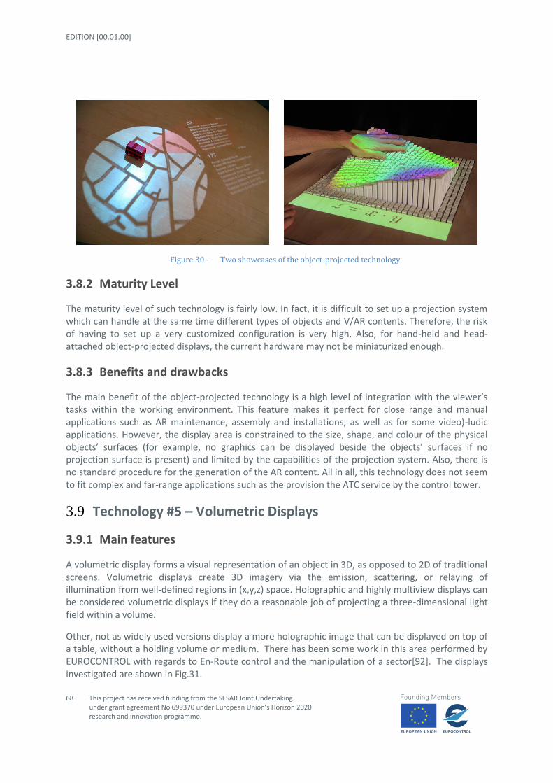
EDITION [00.01.00]
68
This project has received funding from the SESAR Joint Undertaking under grant agreement No 699370 under European Union’s Horizon 2020 research and innovation programme.
Figure 30 - Two showcases of the object-projected technology
3.8.2 Maturity Level
The maturity level of such technology is fairly low. In fact, it is difficult to set up a projection system which can handle at the same time different types of objects and V/AR contents. Therefore, the risk of having to set up a very customized configuration is very high. Also, for hand-held and head-attached object-projected displays, the current hardware may not be miniaturized enough.
3.8.3 Benefits and drawbacks
The main benefit of the object-projected technology is a high level of integration with the viewer’s tasks within the working environment. This feature makes it perfect for close range and manual applications such as AR maintenance, assembly and installations, as well as for some video)-ludic applications. However, the display area is constrained to the size, shape, and colour of the physical objects’ surfaces (for example, no graphics can be displayed beside the objects’ surfaces if no projection surface is present) and limited by the capabilities of the projection system. Also, there is no standard procedure for the generation of the AR content. All in all, this technology does not seem to fit complex and far-range applications such as the provision the ATC service by the control tower.
3.9 Technology #5 – Volumetric Displays
3.9.1 Main features
A volumetric display forms a visual representation of an object in 3D, as opposed to 2D of traditional screens. Volumetric displays create 3D imagery via the emission, scattering, or relaying of illumination from well-defined regions in (x,y,z) space. Holographic and highly multiview displays can be considered volumetric displays if they do a reasonable job of projecting a three-dimensional light field within a volume.
Other, not as widely used versions display a more holographic image that can be displayed on top of a table, without a holding volume or medium. There has been some work in this area performed by EUROCONTROL with regards to En-Route control and the manipulation of a sector[92]. The displays investigated are shown in Fig.31.

STATE OF ART AND INITIAL CONCEPT REQUIREMENTS
This project has received funding from the SESAR Joint Undertaking under grant agreement No 699370 under European Union’s Horizon 2020 research and innovation programme.
69
Figure 31 - Volumetric display of a sector
There is a volumetric display technology consisting of multiple sandwiched LCDs, where the array of 2D pixel layers defines a larger volume of addressable voxels. This type of display has limited transparency and inability to render at a larger stereoscopic depth than the LCDs themselves.
3.9.2 Maturity Level
Volumetric displays are still under development, and have yet to reach the general population. With a variety of systems proposed and in use in small quantities—mostly in academia and various research labs—volumetric displays remain accessible only to academics, corporations, and the military.
3.9.3 Benefits and drawbacks
The benefit of the volumetric display is the ability to see the virtual data in 3D, as well as to allow more than one user to visualize the data at the same time. The drawback is that the visualization is displayed in a fixed location, usually on a desktop or in a ball like volume like in Fig. 32. and draws the controllers attention away from the out-the-window view, which is what the project is trying to reduce.

EDITION [00.01.00]
70
This project has received funding from the SESAR Joint Undertaking under grant agreement No 699370 under European Union’s Horizon 2020 research and innovation programme.
Figure 32 - Example Volumetric Display
One other consideration is the amount of bandwidth required. A volumetric display would need to send about three orders of magnitude more information/second to the display hardware to sustain the image. Furthermore, a 3D volumetric display would require two to three orders of magnitude more CPU and/or GPU power beyond that necessary for 2D imagery of equivalent quality, due at least in part to the sheer amount of data that must be created and sent to the display hardware.
For these reasons, we are choosing to automatically discard this type of visualization technology from consideration. It is described here for completeness.
STATE OF ART AND INITIAL CONCEPT REQUIREMENTS
This project has received funding from the SESAR Joint Undertaking under grant agreement No 699370 under European Union’s Horizon 2020 research and innovation programme.
71
4 Task analysis of the ATC service provision from the control tower
A task analysis of the ATC service provision from the control tower will be performed in both standard and low visibility conditions focusing on how the RETINA concept would impact them. This review will produce operational requirements for the synthetic vision systems and concepts to be developed in WP2.
4.1 Task Analysis Overview
This task description follows on from a study performed within the context of ITWP and involved on site visits to Stockholm Arlanda, London Gatwick, Rome Fiumicino and Naples Capodichino. Following the onsite visits, a comprehensive analysis was performed to breakdown and identify different generic tasks.
This task description is typical of many control towers in that the technological environment may or may not include electronic strips or various controller support tools. What is not included is that this task description is that of a typical current day operation and does not imply any SESAR solution or even Collaborative Decision Making (CDM) messaging and communication systems. In the case of CDM airports for example, ATC departure manager tools issue a TSAT (Target Start Up and Taxi time). Local procedures may be somewhat adapted in accordance with the CDM implementation manual.
4.2 Standard and Low Visibility Task Analysis
4.2.1 Clearance Delivery Controller
Receives all data via the Flight Plan System (FPS) and ensures local strips (paper or electronic) are generated in correct and complete format. Notably the following are crosschecked and verified; NMOC (Network Manager Operations Centre) restrictions, wake turbulence category and aircraft type, and stand number.
Once the aircraft calls for a clearance with ATIS and start-up request (prior to the EOBT - Estimated off Blocks Time), the Clearance Delivery controller activates the flight plan in the Flight Data

EDITION [00.01.00]
72
This project has received funding from the SESAR Joint Undertaking under grant agreement No 699370 under European Union’s Horizon 2020 research and innovation programme.
Processing System. The ATC clearance can then be issued, this includes; SID (Standard Instrument Departure), climb level, local transponder squawk, departure runway, and ground control frequency.
Finally the Clearance Delivery controller advises or coordinates with the Ground controller and Tower Controller.

STATE OF ART AND INITIAL CONCEPT REQUIREMENTS
Figure 33 - Clearance Delivery Controller task analysis

EDITION [00.01.00]
74
This project has received funding from the SESAR Joint Undertaking under grant agreement No 699370 under European Union’s Horizon 2020 research and innovation programme.
4.2.2 Ground Controller
The Ground controller has active control and responsibility for surveillance on the entire airport platform with the exception of the active runway(s).
The Ground controller issues: push back clearance, specific and potentially detailed taxi clearance as well as any restrictions to ensure the safe orderly expeditious flow of traffic (including vehicles) on the airport’s manoeuvring area.
The Ground controller verifies taxi way usage with aircraft type to ensure wing span and PLR (Pavement Load Ratings) are respected.
In the event of an emergency, The Ground controller stops all moving traffic and coordinates with CFR (Crash Fire Response) as well as with the Tower Controller.
In case of Runway Crossing, the Ground controller coordinates directly with the Tower Controller for all active runway crossing clearances (aircraft and vehicles).
In case of LVP, the Ground Controller applies the related restrictions in accordance with the weather conditions. For example, in case of no visibility on the Apron, the Ground Controller approves the push back only for one aircraft in case of multiple push back requests from the same area.
In case of LVP (and in particular in visibility condition 3: RVR<400m), the Ground Controller provides taxi clearance using intermediate holding points in order to ensure adequate spacing between the flights that are moving on the manoeuvring area.

STATE OF ART AND INITIAL CONCEPT REQUIREMENTS
75
This project has received funding from the SESAR Joint Undertaking under grant agreement No 699370 under European Union’s Horizon 2020 research and innovation programme.
Figure 34 - Ground Arrivals Controller task analysis

EDITION [00.01.00]
76
This project has received funding from the SESAR Joint Undertaking under grant agreement No 699370 under European Union’s Horizon 2020 research and innovation programme.
Figure 35 - Ground Departure Controller task analysis
STATE OF ART AND INITIAL CONCEPT REQUIREMENTS
77
This project has received funding from the SESAR Joint Undertaking under grant agreement No 699370 under European Union’s Horizon 2020 research and innovation programme.
4.2.3 Tower Controller
The Tower controller or runway controller is responsible for the active runway(s) and all airborne traffic arriving, departing or overflying. The Tower Controller is also responsible of all the air traffic in the Aerodrome Traffic Zone, i.e. a defined air space around the airport
The Tower controller is responsible for surveillance to ensure aircraft use the correct runways and no unknown traffic enters the control zone. The Tower controller can also likewise monitor any and all safety net warning systems e.g. for runway incursions. The ground A-SMGCS systems can be used to ascertain aircraft positions particular during times of darkness or LVC (Low visibility conditions).
For IFR aircraft, transfer of control (and frequency) from APP to the TWR is typically made once ILS intercept is obtained and for departures immediately after take-off (or as soon as possible after take-off).
For VFR aircraft, the Tower controller ensures VFR or SVFR meteorological conditions permit appropriate operations. A clearance can be then given to a point with in the Control Zone or to a pre-defined point on the traffic pattern, e.g. downwind. Helicopter traffic, even if VFR may likely have different local procedures, landing pads and even entry / departure routes.
In case of Runway Crossing, the Tower controller coordinates with the Ground controller to issue runway crossing clearances (aircraft or vehicles).
The Tower controller coordinates with the Ground controller, clearance delivery controller, Approach control and of course the Tower supervisor if a runway change is required.
The Tower controller is responsible for runway separation notably between Arrivals and Departures or Arrivals only as well as subsequent departures. Separation is adapted as to whether the aircraft is IFR (SID dependant) or VFR as well as within the Heavy Wake Turbulence Category.
Once runway separation is obtained, the Tower controller can issue take-off or landing clearances.
The Tower controller coordinates with the APP controller the gaps in the arrival flow in order to sequence VFR traffic.
The Tower controller coordinates with Approach control if gaps in the arrival flow are required to release pending IFR departures.
In case of LVP, the TWR controller is responsible to apply the related restriction. In particular she/he is responsible to ensure that the critical and sensitive areas of the ILS are always free during the approach

EDITION [00.01.00]
78
This project has received funding from the SESAR Joint Undertaking under grant agreement No 699370 under European Union’s Horizon 2020 research and innovation programme.
Figure 36 - Tower Arrival Controller task analysis

STATE OF ART AND INITIAL CONCEPT REQUIREMENTS
This project has received funding from the SESAR Joint Undertaking under grant agreement No 699370 under European Union’s Horizon 2020 research and innovation programme.
79
Figure 37 - Tower Departure Controller task analysis

EDITION [00.01.00]
80
This project has received funding from the SESAR Joint Undertaking under grant agreement No 699370 under European Union’s Horizon 2020 research and innovation programme.
4.2.4 Tower Supervisor
The Tower supervisor monitors the weather with the hourly weather reports to ensure what aircraft operations can be performed and furthermore which locally published runway configuration shall be utilised.
The Tower supervisor coordinates the Ground controller and with airfield maintenance to ensure runway inspections are performed and in the case of contaminated runways, appropriate actions are taken.
The Tower supervisor coordinates with the Tower controller, clearance delivery controller and Approach control if a runway change is required.
The Tower supervisor coordinates with approach control to identify airport hourly arrival and departure rates and ensures NMOC compliance with appropriate flow restrictions.
In case of LVP, the Tower Supervisor is responsible to coordinate flow restrictions with the Control Center in accordance with the weather and visibility conditions.
In case of LVP, the Tower Supervisor is responsible to inform the flight of the current weather and visibility condition by continuously updating the ATIS messages.
4.2.5 APProach Controller
The APP controller is responsible to provide the air traffic services in the Control Zone around the airport. He is responsible to provide the minimum separation between aircraft in accordance with the airspace classification.
The APP Controller is responsible to sequence the arrivals on the final of the approach procedure in use.
The APP controller coordinates with the TWR controller the gaps between the arrivals to release a departure or to sequence VFR traffic.
In case of LVP the APP controller is responsible to apply the restriction in the arrival flow. Typically the APP controller increase the separation between arrivals on final: for example 5NM in normal weather conditions becomes 10NM in low visibility conditions.
4.3 Operational Requirements
General Introduction to User Requirements
A requirement might be intended as a feature that a system has to have independently from the need where it stems from. Identification and collection of requirements is a process which takes place since the beginning of system lifecycle, as soon as operational concept is defined and consolidated. This process is iterative in order to progressively consolidate identified requirements, which are used as input for the subsequent phase of the system lifecycle.

STATE OF ART AND INITIAL CONCEPT REQUIREMENTS
This project has received funding from the SESAR Joint Undertaking under grant agreement No 699370 under European Union’s Horizon 2020 research
and innovation programme.
81
The generic pattern applied is as follows:
<Object type>-<Project code>-<Document code>-<Reference number 1>.<Reference number 2>
Where:
o <Object type> is REQ o <Project code> is RETINA o <Document code> is D1 o <Reference number 1> specifies the functions or the capability addressed by the
requirement o <Reference number 2> is a sequence number for each series of requirements
Requirement – the following forms have been used:
o “The ATCO 19 using R-CWP20…” to focus on what the user (i.e. controller) is allowed doing by using the R-CWP;
o ”The R-CWP shall allow / display / be able…” to focus on the CWP features.
Identifier REQ-RETINA-D1-XXXX.0001
Requirement The R-CWP shall allow …
XXXX CWP
It shall be possible for an authorised user to…
4.3.1 R-CWP Requirements List
This paragraph lists identified requirements and groups them according to the functionalities/roles identified in the D1.
19 Each operational requirement shall be allocated to the actors mentioned in the document according to their operational needs 20 R-CWP: Will be used to identify the CWP used in the RETINA project

EDITION [00.01.00]
82
This project has received funding from the SESAR Joint Undertaking under grant agreement No 699370 under European Union’s Horizon 2020 research and innovation programme.
4.3.2 General Requirements
Identifier REQ-RETINA-D1-DATA.0001
Requirement The R-CWP shall allow the Tower Supervisor or ATCO to input when Low Visibility Procedures are in progress
Low Visibility Procedures start/stop
This information is required by the Airport Safety Nets, Routing & Planning and Guidance functions
<HMI>
Identifier REQ-RETINA-D1-SETT.0001
Requirement The R-CWP shall provide the ATCO with the possibility to save and load personal settings.
Title CWP setting
Rationale Different ATCOs have different set up preferences for using the CWP. This requirement is applicable for all the Tower ATCO roles
Category <HMI>
Identifier REQ-RETINA-D1-SETT.0002
Requirement The R-CWP shall have a default setting configuration.
Default configuration
ATCOs need to access to default configuration
Identifier REQ-RETINA-D1-SETT.0003
Requirement The ATCO shall be able to reload the default setting configuration in any moment.
Title Default settings
The default CWP configuration shall be reloaded during the duty changes
Identifier REQ-RETINA-D1-VIEW.0001
Requirement The ATCO using the R-CWP shall be able to display additional situation views (picture on picture).

STATE OF ART AND INITIAL CONCEPT REQUIREMENTS
This project has received funding from the SESAR Joint Undertaking under grant agreement No 699370 under European Union’s Horizon 2020 research
and innovation programme.
83
Additional views
ATCOs need to be able to display different views at the same time. This requirement is applicable for all the Tower ATCO roles
<>
Identifier REQ-RETINA-D1-VIEW.0002
Requirement The ATCO using the R-CWP shall be able to adopt a head-mounted display that provides symbolic or pictorial information by introducing into the user's visual pathway a virtual image.
head-mounted display
ATCOs should be able to use head mounted display during the operational activity to have additional info.
<>
Identifier REQ-RETINA-D1-VIEW.0003
Requirement The ATCO using head-mounted display shall be able to see the real world and digitally combined
head-mounted display information
ATCOs should be able to see combined visualization:
Real image
Digital information
<>
Identifier REQ-RETINA-D1-VIEW.0004
Requirement The combined image displayed during the use of head-mounted display shall use harmonized colour coding with R-CWP
head-mounted display colour coding
The display visualization will be harmonized with the R-CWP
<>

EDITION [00.01.00]
84
This project has received funding from the SESAR Joint Undertaking under grant agreement No 699370 under European Union’s Horizon 2020 research and innovation programme.
4.3.3 Operational Requirement
Identifier REQ-RETINA-D1-ATCO.0001
Requirement The R-CWP shall provide the ATCO with the position of all aircraft on the Manoeuvring Area and in the Aerodrome Traffic Zone (final included).
Aircraft surveillance information: position.
This information is required to improve the situational awareness in low visibility conditions.
<HMI>
Identifier REQ-RETINA-D1- ATCO.0002
Requirement The R-CWP shall provide the ATCO with the position of all vehicles on the Manoeuvring Area.
Vehicle surveillance information: position.
This information is required to improve the situational awareness in low visibility conditions.
<HMI>
Identifier REQ-RETINA-D1- ATCO.0003
Requirement The R-CWP shall provide the ATCO with the identification of all aircraft on the Manoeuvring Area and in the Aerodrome Traffic Zone (final included).
Aircraft surveillance information: identification.
This information is required to improve the situational awareness in low visibility conditions.
<HMI>
Identifier REQ-RETINA-D1- ATCO.0004
Requirement The R-CWP shall provide the ATCO with the identification of all vehicles on

STATE OF ART AND INITIAL CONCEPT REQUIREMENTS
This project has received funding from the SESAR Joint Undertaking under grant agreement No 699370 under European Union’s Horizon 2020 research
and innovation programme.
85
the Manoeuvring Area.
Vehicle surveillance information: identification.
This information is required to improve the situational awareness in low visibility conditions.
<HMI>
Identifier REQ-RETINA-D1- ATCO.0005
Requirement The R-CWP shall present the aircraft position to the ATCO in two formats: position symbols and/or “aircraft overlaid image”(i.e., the image of the aircraft as Augmented Reality on the out of window image).
Position information presentation.
This information is required to improve the situational awareness in low visibility conditions.
<HMI>
Identifier REQ-RETINA-D1- ATCO.0006
Requirement The R-CWP shall provide the ATCO with the possibility to set one of the formats in REQ-RETINA-D1-ATCO.0005
Position information presentation.
This information is required to improve the situational awareness in low visibility conditions.
<HMI>
Identifier REQ-RETINA-D1- ATCO.0007
Requirement The R-CWP shall associate to each aircraft and vehicle in the manoeuvring Area a Label with the related information.
Vehicle labels shall be different from Aircraft ones.
Aircraft/vehicle labelling.
This information is required to improve the situational awareness in low visibility conditions.

EDITION [00.01.00]
86
This project has received funding from the SESAR Joint Undertaking under grant agreement No 699370 under European Union’s Horizon 2020 research and innovation programme.
<HMI>
Identifier REQ-RETINA-D1- ATCO.0008
Requirement The label provided by the R-CWP shall have the at least the following information:
Speed
Altitude (*)
Identification
(*) no altitude in vehicle label
Aircraft/vehicle labelling.
This information is required to improve the situational awareness in low visibility conditions.
<HMI>
Identifier REQ-RETINA-D1- ATCO.0009
Requirement The ATCO shall have the possibility to choose between two label dimensions: small and normal
Aircraft/vehicle labelling.
This information is required to improve the situational awareness in low visibility conditions.
<HMI>
Identifier REQ-RETINA-D1- ATCO.0010
Requirement The R-CWP shall provide the ATCO with meteo information as overlay of the out of window view.
Meteo info
This information is required to improve the situational awareness.
<HMI>
Identifier REQ-RETINA-D1- ATCO.0011
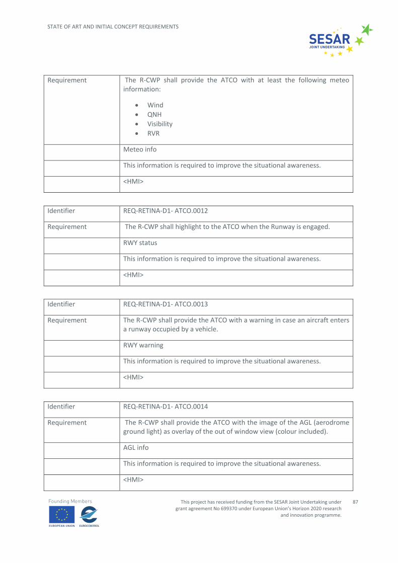
STATE OF ART AND INITIAL CONCEPT REQUIREMENTS
This project has received funding from the SESAR Joint Undertaking under grant agreement No 699370 under European Union’s Horizon 2020 research
and innovation programme.
87
Requirement The R-CWP shall provide the ATCO with at least the following meteo information:
Wind
QNH
Visibility
RVR
Meteo info
This information is required to improve the situational awareness.
<HMI>
Identifier REQ-RETINA-D1- ATCO.0012
Requirement The R-CWP shall highlight to the ATCO when the Runway is engaged.
RWY status
This information is required to improve the situational awareness.
<HMI>
Identifier REQ-RETINA-D1- ATCO.0013
Requirement The R-CWP shall provide the ATCO with a warning in case an aircraft enters a runway occupied by a vehicle.
RWY warning
This information is required to improve the situational awareness.
<HMI>
Identifier REQ-RETINA-D1- ATCO.0014
Requirement The R-CWP shall provide the ATCO with the image of the AGL (aerodrome ground light) as overlay of the out of window view (colour included).
AGL info
This information is required to improve the situational awareness.
<HMI>

EDITION [00.01.00]
88
This project has received funding from the SESAR Joint Undertaking under grant agreement No 699370 under European Union’s Horizon 2020 research and innovation programme.
Identifier REQ-RETINA-D1- ATCO.0015
Requirement The R-CWP shall provide the ATCO with the image of the stop bar once switched on as overlay of the out of window view.
Stopbar info
This information is required to improve the situational awareness.
<HMI>
Identifier REQ-RETINA-D1- ATCO.0016
Requirement The R-CWP shall report to the ATCO the stopbar status: i.e., if they are on (red) or off.
Stopbar info
This information is required to improve the situational awareness.
<HMI>
REQ-RETINA-D1- ATCO.0017
The R-CWP shall provide the ATCO in case of warning from the following systems:
NAV Aids
Surveillance system (radar failure)
AGL
Radio
Equipment failure warning
This information is required to improve the situational awareness.
<HMI>
Identifier REQ-RETINA-D1- ATCO.0018
Requirement The R-CWP shall provide the ATCO with information on the wake vortex of the aircraft on final.
Wake vortex info
This information is required to improve the situational awareness.

STATE OF ART AND INITIAL CONCEPT REQUIREMENTS
This project has received funding from the SESAR Joint Undertaking under grant agreement No 699370 under European Union’s Horizon 2020 research
and innovation programme.
89
<HMI>

EDITION [00.01.00]
90
This project has received funding from the SESAR Joint Undertaking under grant agreement No 699370 under European Union’s Horizon 2020 research and innovation programme.
5 Human Factors & Ergonomics
An analysis of the various technologies categorized in Task 1.1 and Task 1.2 has been performed to investigate the human factors and ergonomic viability, benefits and issues of each.
From a human factors and ergonomics perspective, RETINA investigates different technologies:
Technology #1 – Head Mounted Displays (both VR and See-Through);
Technology #2 – Hand Held Displays (both physical and augmented);
Technology #3 – Spatial Displays (VR, See-Through, SV and holographic displays);
Technology #4 – Object-Projected Displays (i.e. images projected on objects);
Technology #5 – Volumetric Displays.
The application of human factors and ergonomics methods is a key part of the system design, evaluation, and timely implementation. Human Factors and Ergonomics are concerned with designing for human use, and are essentially composed of data, principles and techniques. The data concern human attributes which determine how to achieve good performance, e.g. anthropometric data on body dimensions, or visual data on colour perception, both of which are useful when designing interfaces to ‘fit’ people and help them make sense of what the interface is trying to tell them. Principles may similarly concern how to develop a windows-based environment that is user-friendly rather than cluttered and opaque to the user. Techniques are used to determine detailed aspects of system design, and may be concerned with how to select people for the particular job, or what tasks may be susceptible to error, etc. The Human Factors and Ergonomics professionals’ main activity is therefore applying generalised data, principles and techniques to the specific context being studies, in this case ATM. The Human Factors and Ergonomics specialist must therefore adapt these data and carry out detailed analysis on human performance in the specific context under analysis.
As an example, fast time or model based simulations and real time human-in-the-loop experiments are frequently used with the objective to assess workload, situation awareness and team-working. Prototyping tools then allow early testing of the concept, via simulation methods predicting controller interactions and workload, and small-scale simulation prototyping exercises allow on-line evaluations with samples of real prospective users. Both of these approaches allow insights into the degree of usability and performance with the new system concept before detailed design, and for sure are of help to improve the overall concept development. During detailed design, there is much supportive Human Factors data and many techniques that can enable the system to become highly usable, particularly if a user-centred design philosophy is adopted. As mentioned, prior to the operational implementation of the system, real-time simulations are a valuable means to detect any

STATE OF ART AND INITIAL CONCEPT REQUIREMENTS
This project has received funding from the SESAR Joint Undertaking under grant agreement No 699370 under European Union’s Horizon 2020 research
and innovation programme.
91
residual problems, determine the workload and error impacts of the system on real controllers under realistic operational conditions.
The main Human Factors and Ergonomics areas supposed to be investigated within RETINA Project are the ones related to:
Situational Awareness;
Workload;
Teamwork;
Acceptability;
Usability.
Hereafter it is provided a description of the above mentioned areas.
Situational awareness
Situational awareness is defined as the continuous extraction of environmental information, the integration of this information with previous knowledge to form a coherent mental picture, and the use of that picture in directing further perception and anticipating future events.
In this regard, situational awareness can be considered a mental state consisting of three phases:
Perception of the situation (perception of important elements in the environment);
Comprehension of the situation (integration of different pieces of data in order to determinate their relevance);
Anticipation of future states of the current situation.
To improve the comprehension of the situation for the user, it is important that he is provided with only the information that is needed for his role and/or location and/or the active procedure (i.e. the context) in the tower control environment. If all available information from all services and data sources where to be provided to every user, there is a risk that the data becomes incomprehensible. Therefore, it’s important that the application can adapt itself based on the current context of the user.
Workload
There are two main parts in perceived workload: physical workload and cognitive workload. Cognitive workload has been defined as the degree of processing capacity that is expended during task performance and as being the difference between capacities of the human information processing system that are expected to satisfy performance expectations and that capacity available for actual performance.
Physical workload, on the other hand, is related to the physical actions required to interact with the system in performing tasks (e.g. clicking, making a phone call, moving head to switch form a monitor
EDITION [00.01.00]
92
This project has received funding from the SESAR Joint Undertaking under grant agreement No 699370 under European Union’s Horizon 2020 research and innovation programme.
to another, etc.). In ATM, the mission is to keep operators (ATCOs and pilots) global workload in a range where they are kept (at least mentally) stimulated without going to the point where they become overloaded and start to postpone tasks.
Teamwork
Teamwork and communication refers to the allocation of tasks between team members and the way information is exchanged between them. Changes in team structure can include changes to the composition of a team in terms of roles, as well as, changes to the way in which tasks are allocated between the team members. Such changes may impact the communication flow within a team and the way tasks are performed.
Acceptability
There is a causal relationship between system design features and the user's attitude toward using a system and actual usage behaviour. Among this are the perceived usefulness (extent to which a person believes that using a technology will enhance productivity) and perceived ease of use (extent to which a person believes that using a technology will be free of effort).
The purpose of measuring or testing acceptance is whether there is compliance with specifications and expectations, e.g. usefulness and ease of use. Usually, the goal of most new systems is to improve overall performance. Unfortunately, performance impacts are lost whenever systems are rejected by their users. Thus, a lack of user acceptance can become a serious impediment to the success of new systems and technology and therefore measuring subjective acceptance is a valuable component in the evaluation of systems.
Usability
The usability of a system, as defined by the ISO standard ISO 9241 Part 11, can be measured only by taking into account the context of use of the system — i.e., who is using the system, what they are using it for, and the environment in which they are using it. Furthermore, measurements of usability have several different aspects:
effectiveness (can users successfully achieve their objectives);
efficiency (how much effort and resource is expended in achieving those objectives);
satisfaction (was the experience satisfactory).
5.1 Technology #1 – Head Mounted Displays (both VR and See-Through)
5.1.1 Potential benefits
Head Mounted Displays application in tower control environment could allow reaching different potential benefits with consequent improvements also in terms of Human Performance.
In terms of benefits, HMDs could have an unlimited field-of-regard which means it is capable to provide a panoramic view with information superimposed. A visual coupled system, including HMD, a

STATE OF ART AND INITIAL CONCEPT REQUIREMENTS
This project has received funding from the SESAR Joint Undertaking under grant agreement No 699370 under European Union’s Horizon 2020 research
and innovation programme.
93
head movement tracker and graphic engines can produce corresponding images following the head movement of a controller. This benefit could lead to another new capability of superimposing information and instruction not only over the outside view, but also over control panels and instruments inside the Control Working Position. Also, HMD could provide multicolour display capability and a colour display is beneficial for organizing and highlighting information using colour codes.
The following benefits of HMDs are the most commonly-stated advantages of HMDs which underlie predicted performance gains for various dependent measures.
Increased eyes-on-the-area-of-interest (i.e. aerodrome layout, ground movement, runways, final approaches, etc.) time: Intuitively, the more time a controller spends looking at the airport layout and related traffic the less likely he or she is to miss time-critical events.
HMDs are supposed to reduce the number of head/eye movements under high workload conditions.
First, if head/eye movements are lower under high task demand conditions, HMDs may have some benefit for alleviating fatigue. Secondly, fewer external targets would be missed.
Reduced re-accommodation demands: The benefits here include time to re-accommodate and the amount of accommodation. Since the virtual image is typically located further away than head-down instrument panels, less accommodation is required when switching from external viewing to HMD viewing. Reducing accommodative demands has clear advantages for older controllers due the progressive loss of accommodative range with age.
Reducing the accommodation demands should also increase the HMD advantage by reducing re-accommodation time.
Another advantage of HMDs is that they do not have to be held in the hand or manipulated.
Adoption of HMDs could allow improving controllers’ situational awareness, allowing them to have a complete ad integrate view of the traffic picture to be controlled and monitored.
HMDs should allow controllers to have an overall enriched view of the traffic situation at a glance without having the need to consult different sources of information/displays.
The picture provided to the controllers through HMDs should be fully integrated and consistent so having as consequent benefits as reduction in cognitive workload for controllers to search different information, interpret and integrate them in order to have complete situation awareness.
The major benefit reachable through the application of HMDs devise is supposed to be the reduction of “head-down” time. Head down time is induced by the use of flight strips, A-SMGCS and CPDLC in tower environment and it may have significant impact on the controller’s out-of-the-loop during the time he/she manages the message and/or the system. As consequence the usage of HMDs could allow controllers to reduce the head-down time allowing controllers to monitor surface traffic operations by looking outside of the tower’s window.

EDITION [00.01.00]
94
This project has received funding from the SESAR Joint Undertaking under grant agreement No 699370 under European Union’s Horizon 2020 research and innovation programme.
5.1.2 Associated Issues
A preeminent cognitive factor in assessing controllers’ performance with HMDs is the phenomenon termed “cognitive capture.” This effect describes the degradation of responses to external targets due to the processing of information from a HMD image; as such, it principally involves the cognitive operations of selective attention, divided attention, and attention switching.
Existing data suggest that cognitive interference in users’ responses to external targets is more likely when the number of targets and distracters (in both the HMD and external scene) is large; when the spatial and temporal uncertainty of critical (external) targets is high; when the conspicuity of critical targets is low; and when the relative event rate for salient targets in the forward scene (i.e., those requiring “effortful” or controlled, as opposed to automatic, processing) is lower than that for HMD stimuli. A fundamental premise is that visual information conveyed via HMDs and visual information from the external driving scene are not processed on separate channels; in other words, it is impossible to process both sources of visual information simultaneously.
Furthermore, colourful image also posted another issue with image luminance and contrast, especially in bright daylight condition.
Same as many other augmented reality devices; HMD has a limitation of latency which means a computer generated image is lagged behind the changes of background reality. This latency is caused by communication between image processor, head movement tracker and display. Therefore, latency issue will be a bottleneck for future application unless it can be reduced to an acceptable level. Additionally, clutter is another limitation for HMD. However, for HMD, an additional clutter could be developed due to its capability of unlimited field of regard. Moreover, even though with unlimited field of regard, some experimental subjects reported a reduction on peripheral vision because a limited field of view when using HMD.
Display design/layout is perhaps one of the oldest problems in human factors; namely, how to convey information to controllers that is consistent across their tasks.
Instrumentation advances are a continuous, on-going process which leads to differences in the layout and type of displays.
Carefully designed symbology in itself can determine HMD acceptance among controllers. There are data to support the idea that conformal symbology enhances performance with HMDs. Conformal symbology elements overlay and move with outside world elements that they represent.
On one hand, the application of HMDs could reduce cognitive workload needed to search and integrate information from different sources, on the other hand their usage could provoke an increase of physical workload and a reduction of comfort for controllers due to the fact to have wear a device on their head that could be considered cumbersome and intrusive on long period. Furthermore the adoption of HMDs could not be so acceptable and applicable for people that need to wear glasses to correct sight problems.
Finally HMDs introduction in tower control environment could have negative impact on teamwork and communications, due to the fact that those devices could provoke isolation for each single operation that have his/her own complete situation view, having as consequence difficulties to share information and data with other interested colleagues. They really are used to refer to a common
STATE OF ART AND INITIAL CONCEPT REQUIREMENTS
This project has received funding from the SESAR Joint Undertaking under grant agreement No 699370 under European Union’s Horizon 2020 research
and innovation programme.
95
shared view, that allow them to quickly exchange important data in order to assure an expeditious and safe air traffic control.
5.1.3 Conclusions
Summarising HMDs application for Tower Control environment should be deeply investigated.
It is recommended to perform validation activities to be executed within RETINA project, in order to investigate about the impact of HMDs application for controllers’ human performance.
At time being, the main areas to be investigated are related to workload (both cognitive and physical), situational awareness, teamwork, usability and acceptability.
On one side HMDs is supposed to provide a complete traffic picture including all needed information and data by the controllers consistently integrated and presented. HMDs can only be used by one person at a time; as a result the application running on it can adapt easily to the context of the user. This has the advantage that the controller will not be distracted with irrelevant information.
It should allow improving controllers’ situational awareness, reducing their cognitive workload required to extrapolate information from different sourced and to integrate them together. At the same time Controller Working Position usability should be improved due to the fact that controllers do not need to interact with several different devices but should receive the main needed information through the HMD.
On the other hand it should be investigated if any issues could be encountered by controllers in wearing HMDs that could compromise their acceptability and at the same time could provoke physical workload.
Finally it is recommended to evaluate if application of HMDs in tower control environment could have negative impact on teamwork, reducing team-working, communication and team-sharing among tower controllers’ team.
The following figure provides an overall picture of supposed impacts of HMDs on controllers’ human performance.
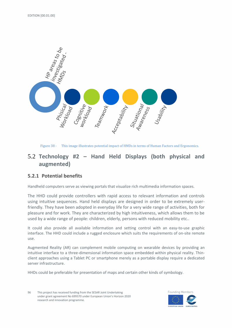
EDITION [00.01.00]
96
This project has received funding from the SESAR Joint Undertaking under grant agreement No 699370 under European Union’s Horizon 2020 research and innovation programme.
Figure 38 - This image illustrates potential impact of HMDs in terms of Human Factors and Ergonomics.
5.2 Technology #2 – Hand Held Displays (both physical and augmented)
5.2.1 Potential benefits
Handheld computers serve as viewing portals that visualize rich multimedia information spaces.
The HHD could provide controllers with rapid access to relevant information and controls using intuitive sequences. Hand held displays are designed in order to be extremely user-friendly. They have been adopted in everyday life for a very wide range of activities, both for pleasure and for work. They are characterized by high intuitiveness, which allows them to be used by a wide range of people: children, elderly, persons with reduced mobility etc..
It could also provide all available information and setting control with an easy-to-use graphic interface. The HHD could include a rugged enclosure which suits the requirements of on-site remote use.
Augmented Reality (AR) can complement mobile computing on wearable devices by providing an intuitive interface to a three-dimensional information space embedded within physical reality. Thin-client approaches using a Tablet PC or smartphone merely as a portable display require a dedicated server infrastructure.
HHDs could be preferable for presentation of maps and certain other kinds of symbology.

STATE OF ART AND INITIAL CONCEPT REQUIREMENTS
This project has received funding from the SESAR Joint Undertaking under grant agreement No 699370 under European Union’s Horizon 2020 research
and innovation programme.
97
5.2.2 Associated issues
At the convenience of mobility, HHDs’ screen sizes are very small, leaving little room for spatial organization. However, such spatial organization of information is essential and exploits human capabilities of spatial memory. Thus, we need methods to virtually increase the screen size; the most widely applied method is scrolling.
Hand held wearable devices pose particular problems for controls and displays because of their small size. Whilst there are problems with small displays, the problems are acute for input devices.
The Display Screen Equipment (DSE) Regulations exclude portable equipment only if it is not in prolonged use. Guidance on "prolonged" is given. [105]is the standard that underpins the Regulations. Most hand held devices differ considerably from the hardware assumed in [105], and so there needs to be an emphasis on risk management. The Provision and Use of Work Equipment Regulations are very wide-ranging and would include hand held devices under most circumstances. Ergonomic requirements are given in [106],which specifies a set of design activities and criteria. It states 'hand held equipment shall have the appropriate dimension, weight, balance and shape for the anatomy of the hand and shall allow the operator to use natural body motions during its use. Operation by both left and right handed operators shall be considered, particularly for hand held equipment.'
Some tasks require that the device can display one or more alarms, e.g. if either the device is in or near a dangerous condition. Space and power constraints can introduce difficulties for alarms in hand held devices. Some devices have had inadequate alarms, including very quiet beeps which were hard to hear in office conditions and the use of video invert or flashing on an LCD display, which was hard to read when looking at the display. There are standards for alarms, and - certainly where plant safety is in any way involved - there are no ergonomic or safety grounds for excluding hand held devices. For many devices, good alarm design has been achieved by using traditional indicator s rather than LCDs or modern technology. Audio feedback is a feature of some devices. It is necessary to ensure that these will be heard over the ambient noise (typical figure is 15 dB above ambient). As yet there are no standard tests for synthetic speech output and tests for voice intelligibility are inappropriate if the speech is synthesised rather than digitised and may be inappropriate for digitised speech. Testing in representative conditions is recommended.
Buttons, keys or touch pads need to give tactile feedback to the operator. Beeps etc. are not sufficient - you can't hear them down below. Keys etc. need to be big enough to accurately and easily enter data. Displays need to be back lit so that the numbers etc. can be clearly seen in poor lighting conditions. An adequate keyboard can be a major problem for hand-held devices.
The range of small pointing devices is continually widening. For the small screens usually associated with hand held devices, fairly crude performance may be acceptable. For a full performance equivalent to a mouse, conformance to ISO 9241 Part 9 should be sought (whereby the supplier will have conducted tests to demonstrate equivalent performance to an established device).
Pen input is currently offered on a number of PDAs and smartphones. The robustness of the screen being used for pen input should be checked, both for normal use and for survival in the environment e.g. grease and dirt.

EDITION [00.01.00]
98
This project has received funding from the SESAR Joint Undertaking under grant agreement No 699370 under European Union’s Horizon 2020 research and innovation programme.
5.2.3 Conclusions
HHDs application for Tower Control environment should be carefully investigated.
It is recommended to include assessments of the impact of HHDs application for controllers’ human performance in the validation activities to be executed within the RETINA project. This will be discussed amongst the members of RETINA's validation team within WP2.
At time being, the main areas to be investigated are related to workload (both cognitive and physical), situational awareness, teamwork, usability and acceptability.
HHD devices could allow controllers to improve situational awareness. Furthermore those devices are usually developed in order to be intuitive and easy to use, so as consequence usability respect to the conventional controller working position should be improved.
Similar to HMDs, HHDs are also personal devices, so the application can adapt to the context of the user.
Due to the fact that such devices are currently of wide usage in everyday life, it is supposed that the acceptability of their application in job environment should be assured.
On the other hand HHDs could have negative impact on teamwork, due to the fact that could provoke, as reported for HMDs, isolation of controllers respect to other colleagues, so reducing or slowing down the process of information sharing and communication.
It is important to adequately design HHDs to be adopted within tower control environment and establish norms and standards about how and when controllers should interact with such device, due to the fact that inappropriate usage and/or long period usage could distract controllers’ attention from other main tasks. Another aspect that could impact negatively on system usability is related the fact that HHD could require controllers to have occupied hands for long time in interacting with such devices.
The following figure provides an overall picture of supposed impacts of HHDs on controllers’ human performance.

STATE OF ART AND INITIAL CONCEPT REQUIREMENTS
This project has received funding from the SESAR Joint Undertaking under grant agreement No 699370 under European Union’s Horizon 2020 research
and innovation programme.
99
Figure 39 - This image illustrates potential impact of HHDs in terms of Human Factors and Ergonomics.
5.3 Technology #3 – Spatial Displays (VR, See-Through, SV and holographic displays)
5.3.1 Potential benefits
Spatial displays transmit information and meaning just as text messages do. The meaningful characteristics of a display, particularly a display involving spatial elements, may be classified into three categories: geometric, dynamic, or symbolic. The geometric features are those describing position, orientation, adjacency, proximity, and connectedness, i.e., the classic geometric characteristics. The rules governing change in the display, e.g., velocities and accelerations, as well as in state changes such as colour in visual displays or timbre in acoustic displays, are the dynamic characteristics. Those features of the display elements that obtain independently of the element’s position or state of motion/change are the display’s symbolic features. They could include such static characteristics as shape, smoothness, roughness, etc. Significantly, these elements may also have their own internal dynamics, e.g. rules for temporal changes of shape. Breaking the display features down into these three categories is not just an academic activity. Each feature and associated sub-features provide a channel that may be used to communicate information and meaning to a user. Because of variations in the transmission environments, e.g., the meaning or context of the intended “messages” and the physical properties of the human sensing systems, communication along any one of these possible channels will have definite limitations. The challenge for any display designer is to insure that sufficient capacity is available for the specific messages and signals they wish to send. This involves matching the coding system to each channel to optimize its use but it also can involve cross feature enhancements. The geometric, dynamic, and symbolic features can be mutually
EDITION [00.01.00]
100
This project has received funding from the SESAR Joint Undertaking under grant agreement No 699370 under European Union’s Horizon 2020 research and innovation programme.
supporting and thereby provide an increased channel capacity and signal redundancy. Designers should think broadly when considering such inter-feature support since it may not only involve different sensory modalities such as vision, audition, or haptics, but can involve within mode enhancements of the geometric, dynamic, or symbolic features.
Perspective displays are widely known to introduce apparent spatial compression into the 2D images on their projection planes. But carefully matched wide-angle distortion can be exploited to compensate for the compression that would otherwise be present on a “correct” projection viewed from the geometric centre of projection. This design feature presents truth through distortion much as cartographers do by accepting map distortion of some features for accurate presentation of others. This accepted distortion is an example of geometric enhancement. The introduction of such an enhancement with the goal of supporting specific communicative needs turns a spatial display into a spatial instrument.
Visual displays are often said to enhance or ‘‘augment’’ cognition. This section summarizes some of the main advantages they afford for cognitive tasks.
First, all types of visual displays are external representations, and therefore store information externally, freeing up working memory resources for other aspects of thinking. This does not mean that there are no internal representations or processes when people use graphical displays. However, the external display can serve as the information store, so that the internal representation at a given time can be quite sparse, perhaps containing only detailed information about a single location of the display being currently viewed and pointers to locations of other important information in the display. Thus, the representation is distributed over sparse internal representations and detailed external representations.
A second advantage of visual-spatial over sentential representations is that they organize information by indexing it spatially. Grouping information that is related is a natural property of iconic displays. In these displays, space in the display represents space in the world, so that if the representation of two items is close in the display, it is likely that those items are also close in the represented world. Things that are close in the natural world tend to be more highly related. Therefore, information that needs to be related in interpreting and making inferences from iconic displays is likely to be represented by visual features that are close in the display. In the more abstract world of digital information, related information is not necessarily physically closer. However, relational displays often organize information such that the representations of related entities are close, facilitating search and integration. Graphs organize entities by placing them in a space defined by the x and y axes. As a result, similar entities are visualized as close together. Moreover, closeness in spatial location is just one aspect of ‘‘display. Proximity in other dimensions such as colour, or achieved by graphical devices (e.g., connecting related items by lines, or enclosing related items with contours) can also facilitate search and integration of disparate sources of information.
In addition to offloading storage, visual displays can allow the offloading of cognitive processes onto perceptual processes as ‘‘using vision to think.’’ When nonvisual data are mapped onto visual variables, patterns often emerge that were not explicitly built in, but which are easily picked up by the visual system. These are referred to as emergent features that is, visual properties of a group of objects that are more salient than properties of the individual objects themselves. They can enable complex computations to be replaced by simple pattern recognition processes.

STATE OF ART AND INITIAL CONCEPT REQUIREMENTS
This project has received funding from the SESAR Joint Undertaking under grant agreement No 699370 under European Union’s Horizon 2020 research
and innovation programme.
101
Furthermore other spatial displays positive aspect is that they not need to be worn. Spatial displays main benefit could be the improvement of spatial awareness for the user as well, due to the fact that large field-of-view images can be generated with greater amount of virtual objects with real world and also to improve sense of immersion if necessary.
Finally, when a display is interactive, people can offload internal mental computations on external manipulations of the display itself.
5.3.2 Associated issues
Although visual-spatial displays can enhance thinking in many ways, this does not mean that their use is necessarily easy or transparent. Display comprehension involves a complex interaction between bottom-up and top-down processes, which are not guaranteed to be successful. First, the visual system senses the features of the display, such as colour and shape, and encodes these features to construct an internal representation of the display. Exactly which of these features are encoded depends on attention, which might be directed by the viewer’s goals and expectations or what is salient in the display. For example, one difficulty in display comprehension might arise if the viewer is distracted by highly salient but task-irrelevant information so that he or she fails to encode the critical information, although it is presented.
In addition to basic perceptual, attentional, and encoding processes, which construct a representation of the external display, the user of a display typically has to apply knowledge to construct a representation of its referent. This can include knowledge of the display conventions, such as the meaning of the x and y axes in a graph, which types of information are typically included in this type of display and which are omitted, which aspects of the display are to be taken literally (such as the relative length and configuration of roads on a road map) and which are not (such as the colour and width).
Again, comprehension can fail if the user’s display schema is incomplete. Understanding a graphic can also include making further inferences based on domain knowledge or visual-spatial processes (comparison, mental rotation, etc.) so that the resulting internal representation comes to contain information that is not presented explicitly in the external display. If the display is interactive, the individual may also choose to change it, for example, by annotating it, zooming in, rotating it, etc. In this case, not just the internal representation, but the external representation changes constantly during the comprehension process. The decision to interact and choice of how to interact with the graphic depends on meta-knowledge of the affordances of that type of display, such as whether it can be zoomed, rotated, or animated. It also depends on meta-knowledge of which interactions with the display are task relevant. This type of understanding has been referred to as meta-representational competence and cannot always be assumed. Moreover, even if users understand the affordances of the interactive display, they might become disoriented as they use interactive features like rotation or zooming.
Not all difficulties with display use can be solved by design. For example, display design cannot compensate for lack of relevant knowledge or meta-representational competence. But good display design can help alleviate some of the problems outlined above. For example, a display can be designed to make task-relevant information salient or eliminate irrelevant information. It can capitalize on cultural conventions (e.g., higher is better; red signifies danger) so that the mapping between the display and its referent is more transparent. It can include landmarks to prevent users

EDITION [00.01.00]
102
This project has received funding from the SESAR Joint Undertaking under grant agreement No 699370 under European Union’s Horizon 2020 research and innovation programme.
from getting disoriented when they rotate or zoom into displays. There are many decisions that a designer has to make in creating a new display, including how much detail to present, what type of graphic (table or graph, network or matrix, etc.), how to map visual variables to the conceptual variables that they represent, and the amount of interactivity to allow. We now turn to a discussion of how cognitive science can inform these decisions.
5.3.3 Conclusions
Spatial displays application for Tower Control environment should be deeply investigated.
It is recommended to perform validation activities to be executed within RETINA project, in order to investigate about the impact of Spatial displays application for controllers’ human performance.
At time being, the main areas to be investigated are related to cognitive workload, situational awareness, usability and acceptability.
Spatial displays could allow controllers to improve situational awareness. However, since these are potentially large displays, to be used by multiple controllers simultaneously, it may be impossible for the application to adapt to the context of a specific user. Thus, there is a risk that too much irrelevant data is shown for some users.
At any rate, the improvement in terms of situational awareness could be obtained just in case high usability would be completely assures.
Spatial displays should be designed in order to present clear information, easy to understand and interpret. Moreover design should take into account as fundamental the rules of consistency and coherency. It should assure that final users (i.e. the controller) would not incur in misunderstanding and/or misleading errors.
As a consequence, the areas, related to human performance, to be seriously investigated are the ones related to cognitive workload and usability.
The following figure provides an overall picture of supposed impacts of Spatial displays on controllers’ human performance.
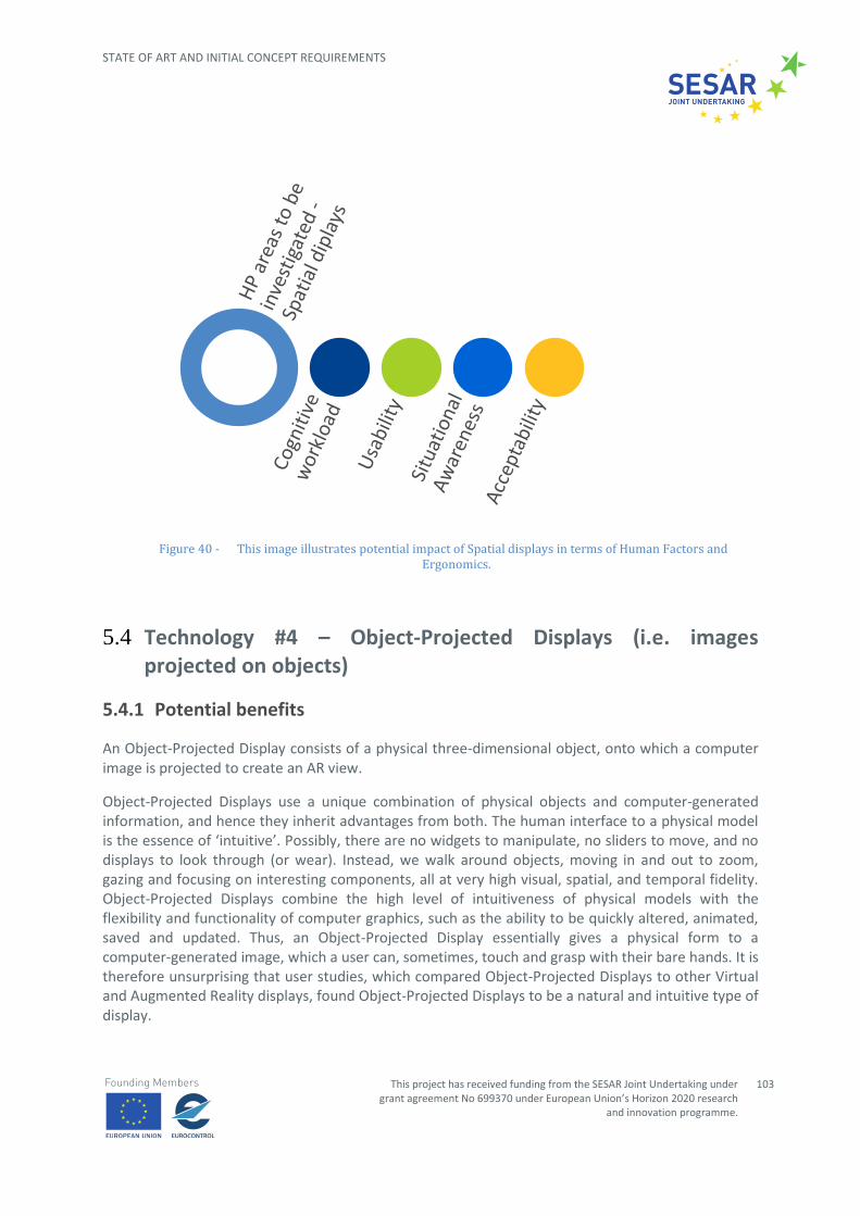
STATE OF ART AND INITIAL CONCEPT REQUIREMENTS
This project has received funding from the SESAR Joint Undertaking under grant agreement No 699370 under European Union’s Horizon 2020 research
and innovation programme.
103
Figure 40 - This image illustrates potential impact of Spatial displays in terms of Human Factors and Ergonomics.
5.4 Technology #4 – Object-Projected Displays (i.e. images projected on objects)
5.4.1 Potential benefits
An Object-Projected Display consists of a physical three-dimensional object, onto which a computer image is projected to create an AR view.
Object-Projected Displays use a unique combination of physical objects and computer-generated information, and hence they inherit advantages from both. The human interface to a physical model is the essence of ‘intuitive’. Possibly, there are no widgets to manipulate, no sliders to move, and no displays to look through (or wear). Instead, we walk around objects, moving in and out to zoom, gazing and focusing on interesting components, all at very high visual, spatial, and temporal fidelity. Object-Projected Displays combine the high level of intuitiveness of physical models with the flexibility and functionality of computer graphics, such as the ability to be quickly altered, animated, saved and updated. Thus, an Object-Projected Display essentially gives a physical form to a computer-generated image, which a user can, sometimes, touch and grasp with their bare hands. It is therefore unsurprising that user studies, which compared Object-Projected Displays to other Virtual and Augmented Reality displays, found Object-Projected Displays to be a natural and intuitive type of display.

EDITION [00.01.00]
104
This project has received funding from the SESAR Joint Undertaking under grant agreement No 699370 under European Union’s Horizon 2020 research and innovation programme.
5.4.2 Associated issues
An Object-Projected Display often aims to create the illusion of actually being the object that it depicts. For example, when used for a product design application, it is important that an Object-Projected Display model provides a convincing perceptual impression of actually being the final product.
The situation in which an Object-Projected Display is perceived to actually be the object that it depicts is sometimes referred as named ‘Projection Augmented model illusion’. However, the essence of this illusion does not involve deceiving the user. A user can perceive an Object-Projected Display to be the object that it depicts, whilst knowing that it is actually a white model and a projected image.
Technology has been developed to enhance this illusion by increasing the physical similarity between the Object-Projected Display and the object that it depicts, or in other words, increasing the fidelity of the Object-Projected Displays. For example, the way in which the specular highlights on an object move as the viewer changes position can be dynamically simulated. This enables an Object-Projected Display to appear to be made from a wide range of materials. For example, a dull clay vase can appear to be made from a shiny plastic material.
However, whether or not the Object-Projected Display illusion occurs is entirely dependent on a user’s subjective perceptual impression and, also, not necessarily beneficial. It cannot be assumed that increasing the fidelity of any aspect of an Object-Projected Display will automatically strengthen the Object-Projected Display efficacy, and similarly it cannot be assumed that decreasing the fidelity of any aspect will automatically weaken it. Therefore, given that no previous research has investigated this illusion, it is difficult to determine the success of the technology that aims to enhance it, and difficult to make informed decisions when developing new technology. The capabilities of the human perceptual system should guide the development of any advanced interface; hence this issue needs to be addressed.
5.4.3 Conclusions
It is not still identified if application of Object-Projected Displays could be in tower control environment and if it could imply any benefits for controllers.
It may be advantageous to execute a workshop and/or focus group with technical, operative and human factors experts in order to elicit potential applications of Object-Projected Displays in ATM context.
At the time being it is supposed that potential application of Object-Projected Displays in tower control environment could have potential impact on the Human Factors area highlighted in Fig.41.
The following figure provides an overall picture of supposed impacts of Object-Projected Displays on controllers’ human performance.
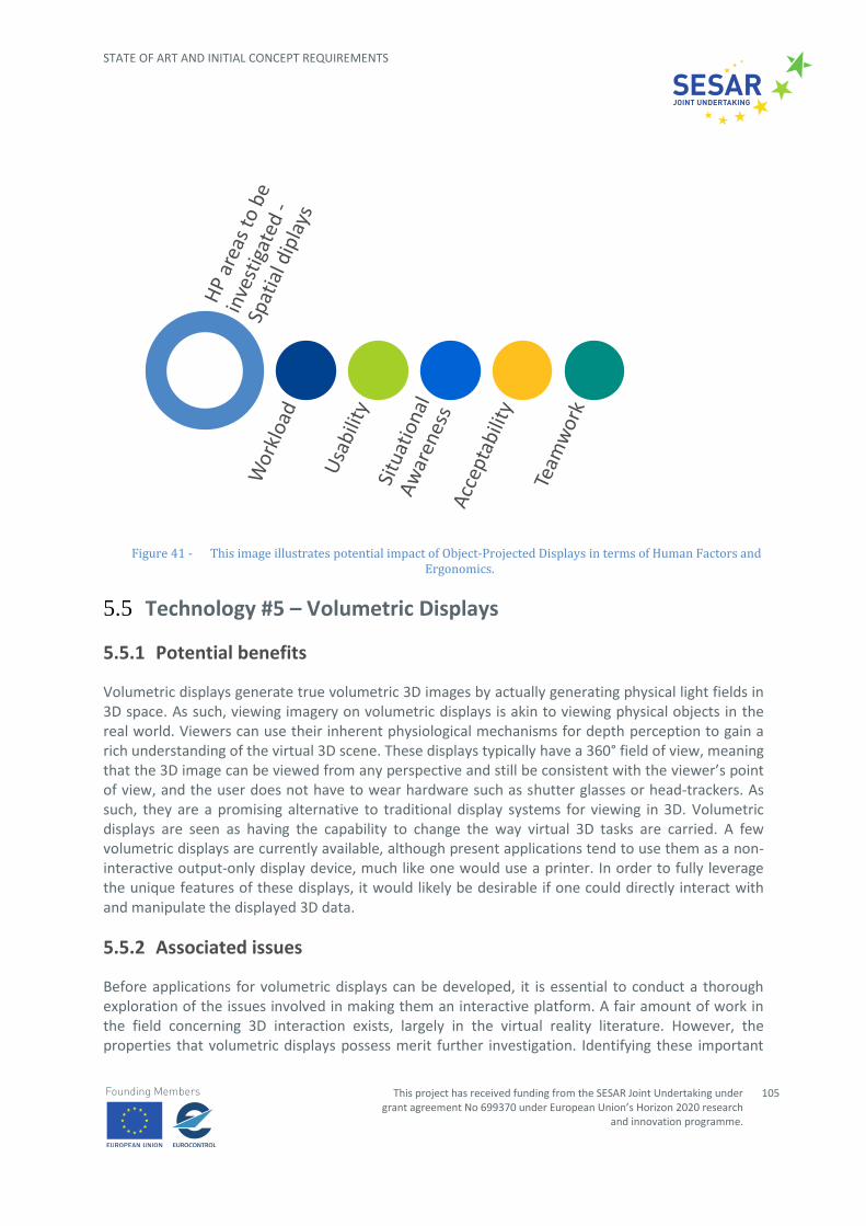
STATE OF ART AND INITIAL CONCEPT REQUIREMENTS
This project has received funding from the SESAR Joint Undertaking under grant agreement No 699370 under European Union’s Horizon 2020 research
and innovation programme.
105
Figure 41 - This image illustrates potential impact of Object-Projected Displays in terms of Human Factors and Ergonomics.
5.5 Technology #5 – Volumetric Displays
5.5.1 Potential benefits
Volumetric displays generate true volumetric 3D images by actually generating physical light fields in 3D space. As such, viewing imagery on volumetric displays is akin to viewing physical objects in the real world. Viewers can use their inherent physiological mechanisms for depth perception to gain a rich understanding of the virtual 3D scene. These displays typically have a 360° field of view, meaning that the 3D image can be viewed from any perspective and still be consistent with the viewer’s point of view, and the user does not have to wear hardware such as shutter glasses or head-trackers. As such, they are a promising alternative to traditional display systems for viewing in 3D. Volumetric displays are seen as having the capability to change the way virtual 3D tasks are carried. A few volumetric displays are currently available, although present applications tend to use them as a non-interactive output-only display device, much like one would use a printer. In order to fully leverage the unique features of these displays, it would likely be desirable if one could directly interact with and manipulate the displayed 3D data.
5.5.2 Associated issues
Before applications for volumetric displays can be developed, it is essential to conduct a thorough exploration of the issues involved in making them an interactive platform. A fair amount of work in the field concerning 3D interaction exists, largely in the virtual reality literature. However, the properties that volumetric displays possess merit further investigation. Identifying these important
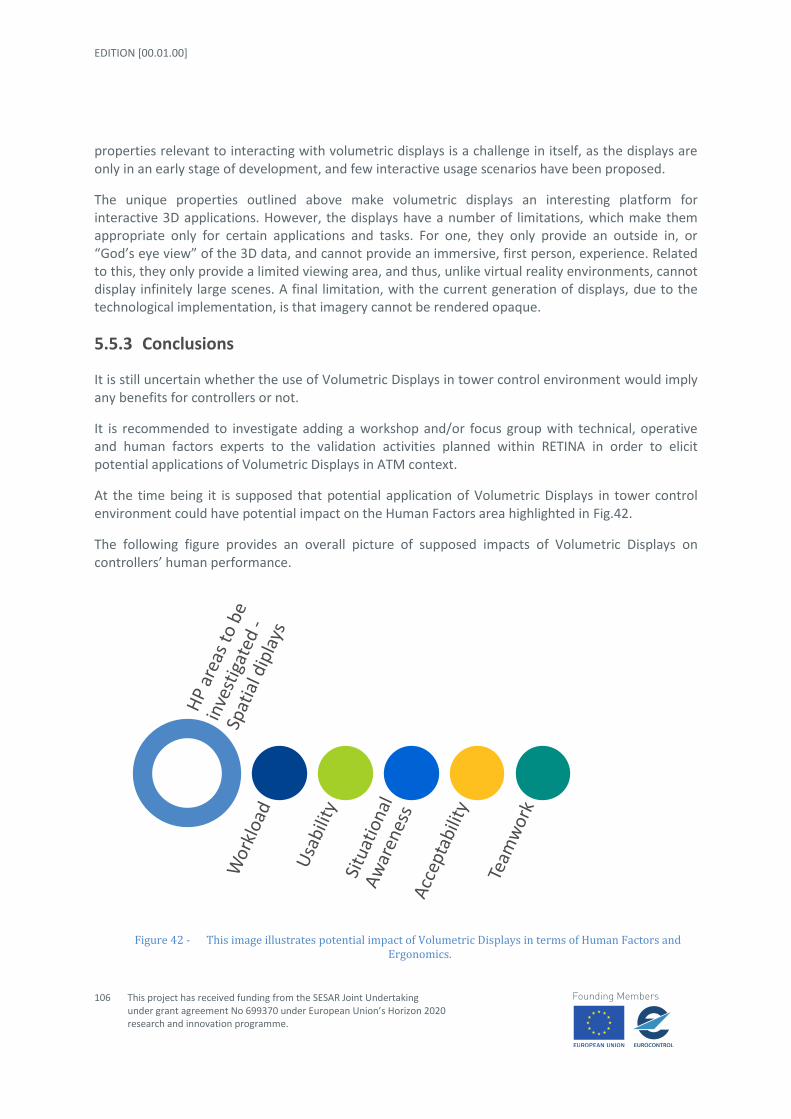
EDITION [00.01.00]
106
This project has received funding from the SESAR Joint Undertaking under grant agreement No 699370 under European Union’s Horizon 2020 research and innovation programme.
properties relevant to interacting with volumetric displays is a challenge in itself, as the displays are only in an early stage of development, and few interactive usage scenarios have been proposed.
The unique properties outlined above make volumetric displays an interesting platform for interactive 3D applications. However, the displays have a number of limitations, which make them appropriate only for certain applications and tasks. For one, they only provide an outside in, or “God’s eye view” of the 3D data, and cannot provide an immersive, first person, experience. Related to this, they only provide a limited viewing area, and thus, unlike virtual reality environments, cannot display infinitely large scenes. A final limitation, with the current generation of displays, due to the technological implementation, is that imagery cannot be rendered opaque.
5.5.3 Conclusions
It is still uncertain whether the use of Volumetric Displays in tower control environment would imply any benefits for controllers or not.
It is recommended to investigate adding a workshop and/or focus group with technical, operative and human factors experts to the validation activities planned within RETINA in order to elicit potential applications of Volumetric Displays in ATM context.
At the time being it is supposed that potential application of Volumetric Displays in tower control environment could have potential impact on the Human Factors area highlighted in Fig.42.
The following figure provides an overall picture of supposed impacts of Volumetric Displays on controllers’ human performance.
Figure 42 - This image illustrates potential impact of Volumetric Displays in terms of Human Factors and Ergonomics.

STATE OF ART AND INITIAL CONCEPT REQUIREMENTS
This project has received funding from the SESAR Joint Undertaking under grant agreement No 699370 under European Union’s Horizon 2020 research
and innovation programme.
107
5.6 Human Factors and Ergonomics Recommendations
Reviewing the individual conclusions regarding each technology, the following things can be recommended for WP2 and the RETINA validation activities.
It is recommended that RETINA focus its validation activities on the application of HMD, HHD, and Spatial displays. The application of volumetric and Object Projected Displays in the control tower show limited benefits at best.
Validation activities performed within RETINA project, should focus on areas related to workload (both cognitive and physical), situational awareness, teamwork, usability and acceptability in order to compare and contrast the impact of HMD, HHD, and Spatial displays on controllers’ human performance in the Tower environment.
With regards to HMDs, issues which could compromise its acceptability and at the same time could provoke physical workload should be investigated. It is also recommended to evaluate if the application of HMDs in the tower control environment could have a negative impact on teamwork, reducing team-working, communication and team-sharing among tower controllers’ team.
With regards to HHDs, validation activities should include addressing the possible isolation of controllers with respect to other colleagues, reducing or slowing down the process of information sharing and communication. They should also address if HHDs could require too many interactions increasing both physical and mental workload, the first one needed to interact with the device and the second one to remember how to access to the needed information. Also, HHD could require controllers to have occupied hands for a long time by interacting with such devices.
With regards to Spatial Devices, since these are potentially large displays, to be used by multiple controllers simultaneously, it may be impossible for the application to adapt to the context of a specific user. Thus, the validation activities should address the risk that too much irrelevant data might be shown for some users.
EDITION [00.01.00]
108
This project has received funding from the SESAR Joint Undertaking under grant agreement No 699370 under European Union’s Horizon 2020 research and innovation programme.
6 References
[1] COMMISSION IMPLEMENTING REGULATION (EU) No 1207/2011; 22/11/2011
[2] HTTP://WWW.NAVCANADA.CA/EN/PRODUCTS-AND-SERVICES/PAGES/ON-BOARD-
OPERATIONAL-INITIATIVES-ADS-B.ASPX
[3] HTTP://WWW.EUROCONTROL.INT/ARTICLES/ADVANCED-SURFACE-MOVEMENT-GUIDANCE-
AND-CONTROL-SYSTEMS-SMGCS
[4] HTTP://WWW.SESARDEPLOYMENTMANAGER.EU/EMAILS/MONTHLY-NEWSLETTER-2-
20160401/
[5] SWIM introduction, http://www.eurocontrol.int/swim
[6] SWIM standards overview presented during the SESAR SWIM Master Class 2015 kick-off
meeting:
http://www.sesarju.eu/sites/default/files/documents/swim/SWIM_Master_Class_2015_Stan
dards_v00.00.pdf
[7] ICAO Annex III, http://www.wmo.int/pages/prog/www/ISS/Meetings/CT-MTDCF-ET-
DRC_Geneva2008/Annex3_16ed.pdf
[8] WXXM introduction, http://www.wxxm.aero/public/subsite_homepage/homepage.html
[9] OGC’s approval of the Climate and Forecast (CF) extension to NetCDF Core data model
standard- http://www.opengeospatial.org/pressroom/pressreleases/1783
[10] Avionics Magazine / Synthetic Vision Systems;
[11] Regulators, Market To Determine Fate Of Synthetic Vision Guidance Systems | Business
Aviation
[12] The use of surveillance data in augmented reality system to assist control tower operations;
Alexandre Silva, Eduardo Ferreira, Normand Laforge and Sérgio Carvalho; IEEEXplore;
2015
[13] The history of augmented reality
[14] A Survey of Augmented Reality ;Azuma, Ronald; Presence: Teleoperators and Virtual
Environments, pp. 355–385, August 1997
[15] Defining Virtual Reality: Dimensions Determining Telepresence, Steuer, Jonathan;
Department of Communication, Stanford University. 15 October 1993.
[16] Virtual Reality Systems; R.A. Earshaw, M.A. Gigante, H. Jones; ISBN 0-12-227748-1;
1993
[17] "Augmented Reality in Education and Training" (Techtrends: Linking Research & Practice
To Improve Learning 56 (2). Lee, Kangdon (March 2012).
[18] L. B. Rosenberg. The Use of Virtual Fixtures As Perceptual Overlays to Enhance Operator
Performance in Remote Environments. Technical Report AL-TR-0089, USAF Armstrong
Laboratory, Wright-Patterson AFB OH, 1992.
[19] Julier, S. J., Y. Baillot, M. Lanzagorta, D. G. Brown, and L. J. Rosenblum, "BARS:
Battlefield Augmented Reality System", NATO Symposium on Information Processing
Techniques for Military Systems, Istanbul, Turkey, 10/2000.
[20] Design of Augmented Reality Tools forAir Traffic Control Towers; Ronald J. Reisman,
David M. Brown; 6th AIAA Aviation Technology Integration and Operations Conference
(ATIO), Sept. 2016

STATE OF ART AND INITIAL CONCEPT REQUIREMENTS
This project has received funding from the SESAR Joint Undertaking under grant agreement No 699370 under European Union’s Horizon 2020 research
and innovation programme.
109
[21] Ian White, "The History of Air Intercept Radar & the British Nightfigher", Pen & Sword,
2007, p. 207
[22] http://www.gulfstream.com/technology/planeview
[23] Gaze-Coupled Perspective for Enhanced Three-Dimensional Human-Computer Interfaces
in Aeronautics
[24] Augmented Reality in the Control Tower: a Rendering Pipeline for Multiple Head-Tracked
Head-Up Displays
[25] Comparison Between Particle Filter Approach and Kalman Filter-Based Technique For
Head Tracking in Augmented Reality Systems; Fakhr-eddine Ababsa, Malik Mallem and
David Roussel; 2004 IEEE International Conhrsnce on Robotics 6 Automation
[26] Let’s look at the Cockpit: Exploring Mobile Eye-Tracking for Observational Research on
the Flight Deck; Nadir Weibel, Adam Fouse, Colleen Emmenegger, Sara Kimmich, Edwin
Hutchins; ETRA 2012,
[27] US Patent 20160187654; SEE-THROUGH NEAR-EYE DISPLAY GLASSES WITH A
LIGHT TRANSMISSIVE WEDGE SHAPED ILLUMINATION SYSTEM ; June 30, 2016
[28] Peterson, Stephen, and Ella Pinska, “Human Performance with simulated Collimation in
Transparent Projection Screens,” in Proceedings of the Second International Conference on
Research in Air Transportation (ICRAT), 2006.
[29] O. Bimber and R. Raskar, Spatial Augmented Reality: Merging Real and Virtual Worlds.
Natick, MA, USA: A. K. Peters, Ltd., 2005.
[30] C. Anthes, R. J. Garcia-Hernandez, M. Wiedemann, and D. Kranzlmuller, “State of the art
of virtual reality technology,” 2016, pp. 1–19.
[31] N. Masotti, F. De Crescenzio, and S. Bagassi, “Augmented Reality in the Control Tower:
A Rendering Pipeline for Multiple Head-Tracked Head-up Displays,” in Augmented
Reality, Virtual Reality, and Computer Graphics: Third International Conference, AVR
2016, Lecce, Italy, June 15-18, 2016. Proceedings, Part I, T. L. De Paolis and A. Mongelli,
Eds. Cham: Springer International Publishing, 2016, pp. 321–338.
[32] F. Solari, M. Chessa, M. Garibotti, and S. P. Sabatini, “Natural perception in dynamic
stereoscopic augmented reality environments,” Displays, vol. 34, no. 2, pp. 142 – 152,
2013.
[33] A. M. Puerta, “The power of shadows: shadow stereopsis,” J. Opt. Soc. Am. A, vol. 6, no.
2, pp. 309–311, Feb. 1989.
[34] S. Nagata, “Visual depth sensitivities of various cues for depth perception.,” NHK Lab.
Note, vol. 266, pp. 1–11, 1981.
[35] J. E. Cutting and P. M. Vishton, “Perceiving layout and knowing distances: The
integration, relative potency, and contextual use of different information about depth,” W
Epstein Rogers Eds Handb. Percept. Cogn., vol. Vol 5; Perception of space and motion, pp.
69–117, Academic press, San Diego (CA 1995.
[36] S. Palmisano, B. Gillam, D. G. Govan, R. S. Allison, and J. M. Harris, “Stereoscopic
perception of real depths at large distances,” J. Vis., vol. 10(6):19, pp. 1–16, 2010.
[37] H. J. Howard, “A Test for the Judgment of Distance,” Trans. Am. Ophthalmol. Soc., vol.
17, pp. 195–235, 1919.
[38] H. Helmholtz, Treatise on Physiological Optics(1909/1925), vol. vol. 3: Visual Perception.
James P.C. Southall, Optical Society of America, 1925.
[39] G. Kramida and A. Varshney, “Resolving the Vergence-Accommodation Conflict in Head
Mounted Displays,” IEEE Trans. Vis. Comput. Graph. Issue 07, vol. 22, pp. 1912–31, Jul.
2016.
[40] D. M. Hoffman, A. R. Girshick, K. Akeley, and M. S. Banks, “Vergence-accommodation
conflicts hinder visual performance and cause visual fatigue,” J. Vis., vol. vol. 8, no. 3, pp.
33.1–30, Jan. 2008.

EDITION [00.01.00]
110
This project has received funding from the SESAR Joint Undertaking under grant agreement No 699370 under European Union’s Horizon 2020 research and innovation programme.
[41] M. Lambooij, W. Ijsselsteijn, M. Fortuin, and I. Heynderickx, “Visual Discomfort and
Visual Fatigue of Stereoscopic Displays: A Review,” J. Imaging Sci. Technol., vol. vol. 53,
no. 3, p. 030201, 2009.
[42] S. Reichelt, R. Häussler, G. Fütterer, and N. Leister, “Depth cues in human visual
perception and their realization in 3D displays,” in SPIE Defense, Security, and Sensing,
2010, p. 76 900B–76 900B–12.
[43] T. Bando, A. Iijima, and S. Yano, “Visual fatigue caused by stereoscopic images and the
search for the requirement to prevent them: A review,” Displays, vol. 33, no. 2, pp. 76 –
83, 2012.
[44] A. Shamir and O. Sorkine, “Visual Media Retargeting,” in ACM SIGGRAPH ASIA 2009
Courses, New York, NY, USA, 2009, pp. 11:1–11:13.
[45] M. Lang, A. Hornung, O. Wang, S. Poulakos, A. Smolic, and M. Gross, “Nonlinear
Disparity Mapping for Stereoscopic 3D,” in ACM SIGGRAPH 2010 Papers, New York,
NY, USA, 2010, pp. 75:1–75:10.
[46] Y. Liu, L. Sun, and S. Yang, “A retargeting method for stereoscopic 3D video,” Comput.
Vis. Media, vol. 1, no. 2, pp. 119–127, 2015.
[47] P. Didyk, T. Ritschel, E. Eisemann, K. Myszkowski, H.-P. Seidel, and W. Matusik, “A
Luminance-contrast-aware Disparity Model and Applications,” ACM Trans Graph, vol. 31,
no. 6, pp. 184:1–184:10, Nov. 2012.
[48] A. Sherstyuk, A. Dey, C. Sandor, and A. State, “Dynamic Eye Convergence for Head-
mounted Displays Improves User Performance in Virtual Environments,” in Proceedings of
the ACM SIGGRAPH Symposium on Interactive 3D Graphics and Games, New York,
NY, USA, 2012, pp. 23–30.
[49] T. Oskam, A. Hornung, H. Bowles, K. Mitchell, and M. Gross, “OSCAM - Optimized
stereoscopic camera control for interactive 3D,” ACM Trans Graph. Proc SIGGRAPH, vol.
30, no. 6, pp. 189:1–189:8, 2011.
[50] U. Celikcan, G. Cimen, E. B. Kevinc, and T. Capin, “Attention-Aware Disparity Control in
interactive environments,” Vis. Comput., vol. 29, no. 6, pp. 685–694, 2013.
[51] J. P. Rolland, M. W. Krueger, and A. A. Goon, “Dynamic focusing in head-mounted
displays,” 1999, vol. 3639, pp. 463–470.
[52] K. J. Ciuffreda, B. Wang, and D. Wong, “Central and near peripheral retinal contributions
to the depth-of-focus using naturalistic stimulation,” Vision Res., vol. 45, no. 20, pp. 2650–
2658, Sep. 2005.
[53] R. Suryakumar, J. P. Meyers, E. L. Irving, and W. R. Bobier, “Vergence accommodation
and monocular closed loop blur accommodation have similar dynamic characteristics,”
Vision Res., vol. 47, no. 3, pp. 327–337, Feb. 2007.
[54] J. E. Melzer, “Head-Mounted Displays,” Kaiser Electro-Optics Inc., 2001.
[55] D. F. Mc Allister, “Display Technology: Stereo & 3D Display Technologies.” Mar-2003.
[56] S. Peterson, “Very large format stereoscopic head-up display for the airport tower,” in In
Proceedings of the Virtual Images Seminar, number 16. CNRS/Renault, 2007.
[57] R. J. Sojourner and J. F. Antin, “The Effects of a Simulated Head-Up Display Speedometer
on Perceptual Task Performance,” Hum. Factors J. Hum. Factors Ergon. Soc., vol. 32, no.
3, pp. 329–339, 1990.
[58] H. Kato, H. Ito, J. Shima, M. Imaizumi, and H. Shibata, “Development of a hologram head
up display,” 1992.
[59] J. P. Rolland, Y. Baillot, and A. A. Goon, “A Survey of Tracking Technology for Virtual
Environments,” Fundam. Wearable Comput. Augment. Real., pp. 67–112 (chap. 3), 2001.
[60] F. Zhou, H. B.-L. Duh, and M. Billinghurst, “Trends in augmented reality tracking,
interaction and display: A review of ten years of ISMAR,” in Mixed and Augmented
Reality, 2008. ISMAR 2008. 7th IEEE/ACM International Symposium on, 2008, pp. 193–

STATE OF ART AND INITIAL CONCEPT REQUIREMENTS
This project has received funding from the SESAR Joint Undertaking under grant agreement No 699370 under European Union’s Horizon 2020 research
and innovation programme.
111
202.
[61] Nicola Masotti and Franco Persiani, “Gaze-Coupled Perspective for Enhanced Human-
Machine Interfaces in Aeronautics,” presented at the Conferences in Air Transport &
Operations, Delft University of Technology, Delft, The Netherlands., 2015.
[62] M. Velger, “Helmet-Mounted Displays and Sights,” Disp. 21139–40, Mar. 2000.
[63] C. E. Rash and R. W. Verona, The human factor considerations of image intensification
and thermal imaging systems, vol. chap. 16. New York, Marcel Dekker: Karim, M. A.,
1992.
[64] K. W. Moffitt, “Ocular responses to monocular and binocular helmet-mounted display
configurations,” in SPIE, Helmet-Mounted Displays, 1116, 1989, p. 142.
[65] K. R. Boff and J. E. Lincoln, “Engineering Data Compendium, Human Perception and
Performance.” Human Engineering Division, Harry G. Armstrong Aerospace Medical
Research Laboratory, Wright-Patterson Air Force Base, OH, 1988.
[66] K. W. Moffitt, Designing HMDs for viewing comfort, vol. cap. 5. New York: Melzer, J. E.
and Moffitt, K. W., Eds., McGraw-Hill, 1997.
[67] Stephen R. Ellis, Bernard D. Adelstein, Ronald J. Reisman, Joelle R. Schmidt-Ott,
Jonathan Gips, and Jimm Krozel, “Augmented Reality in a Simulated Tower Environment:
Effect of Field of View on Aircraft Detection,” NASA Ames Research Center Technical
Reports, NASA/TM-2002-211853, NAS 1.15:211853, IH-025, Sep. 2002.
[68] D. E. Thorpe, Visual Requirements in HMDs: What can we see and what do we need to
see? New York: Mc Graw-Hill.: J.E. Melzer & KMoffit (Eds.), 1997.
[69] M. J. Wells and M. Venturio, “Performance and head movements using a helmet-mounted
display with different fields-of-view.,” Opt. Eng., vol. 29 (8), pp. 870–877., 1990.
[70] M. Fiorentino, S. Debernardis, A. E. Uva, and G. Monno, “Augmented reality text style
readability with see-through head-mounted displays in industrial context,” Presence
Teleoperators Virtual Environ., vol. 22, no. 2, pp. 171–190, 2013.
[71] S. Debernardis, M. Fiorentino, M. Gattullo, G. Monno, and A. E. Uva, “Text Readability in
Head-Worn Displays: Color and Style Optimization in Video versus Optical See-Through
Devices,” IEEE Trans. Vis. Comput. Graph., vol. 20, no. 1, pp. 125–139, Jan. 2014.
[72] L. Arbuthnot, B. Aitchison, C. Carlsen, C. N. King, T. Larsson, and T. Nguyen, “High-
luminance active matrix electroluminescent (AMEL) display for see-through symbology
applications,” 1999, vol. 3689, pp. 260–268.
[73] H. Urey, “Optical advantages in retinal scanning displays,” 2000, vol. 4021, pp. 20–26.
[74] H. Urey, N. Nestorovic, B. S. Ng, and A. A. Gross, “Optics designs and system MTF for
laser scanning displays,” 1999, vol. 3689, pp. 238–248.
[75] J. P. Sauerborn, “Advances in miniature projection CRTs for helmet displays,” 1992, vol.
1695, pp. 102–116.
[76] S. Liu, H. Hua, and D. Cheng, “A novel prototype for an optical see-through head-mounted
display with addressable focus cues,” IEEE Trans. Vis. Comput. Graph., vol. 16, no. 3, pp.
381–393, 2010.
[77] H. Hua and C. Gao, “A compact eyetracked optical see-through head-mounted display,”
2012, vol. 8288, p. 82881F–82881F–9.
[78] M. Vinnikov and R. S. Allison, “Gaze-contingent Depth of Field in Realistic Scenes: The
User Experience,” in Proceedings of the Symposium on Eye Tracking Research and
Applications, New York, NY, USA, 2014, pp. 119–126.
[79] M. Day, D. Seidel, L. S. Gray, and N. C. Strang, “The effect of modulating ocular depth of
focus upon accommodation microfluctuations in myopic and emmetropic subjects,” Vision
Res., vol. 49, no. 2, pp. 211 – 218, 2009.
[80] L. O’Hare, T. Zhang, H. T. Nefs, and P. B. Hibbard, “Visual discomfort and depth-of-
field,” -Percept., vol. 4, no. 3, pp. 156–169, 2013.

EDITION [00.01.00]
112
This project has received funding from the SESAR Joint Undertaking under grant agreement No 699370 under European Union’s Horizon 2020 research and innovation programme.
[81] K. J. MacKenzie and S. J. Watt, “Eliminating accommodation-convergence conflicts in
stereoscopic displays: Can multiple-focal-plane displays elicit continuous and consistent
vergence and accommodation responses?,” 2010, vol. 7524, pp. 752417–752417–10.
[82] S. D. Peterson, “Stereoscopic Label Placement: Reducing Distraction and Ambiguity in
Visually Cluttered Displays,” Dissertations, No. 1293, Linköping University, Division of
Visual Information Technology and Applications (VITA) Department of Science and
Technology, Linköping University SE-601 74 Norrköping, Sweden, 2009.
[83] W. Krueger and B. Froehlich, “The Responsive Workbench,” IEEE Comput Graph Appl,
vol. 14, no. 3, pp. 12–15, May 1994.
[84] Persiani F., De Crescenzio F., Fantini M., and Bagassi S., “A Tabletop-Based Interface to
Simulate Air Traffic Control in a Distributed Virtual Environment,” in AA.VV., Atti del
XVI Congresso ADM e XIX Congreso Ingegraf, PI, ETS, 2007, Perugia, Italy, 2007.
[85] F. Persiani and A. Liverani, “A Semi-Immersive Synthetic Environment for Cooperative
Air Traffic Control,” in Proceedings of the 22nd Congress of International Council of the
Aeronautical Sciences, Harrogate, UK, 2000.
[86] C. Cruz-Neira, D. J. Sandin, and T. A. DeFanti, “Surround-screen Projection-based Virtual
Reality: The Design and Implementation of the CAVE,” in Proceedings of the 20th Annual
Conference on Computer Graphics and Interactive Techniques, New York, NY, USA,
1993, pp. 135–142.
[87] T. A. DeFanti, G. Dawe, D. J. Sandin, J. P. Schulze, P. Otto, J. Girado, F. Kuester, L.
Smarr, and R. Rao, “The StarCAVE, a third-generation {CAVE} and virtual reality
OptIPortal,” Future Gener. Comput. Syst., vol. 25, no. 2, pp. 169 – 178, 2009.
[88] A. Liverani, F. Persiani, and F. De Crescenzio, “An Immersive Reconfigurable Room
(I.R.R.) for Virtual Reality Simulation,” in Electronic Proceedings of 12th International
Conference on Design Tools and Methods in Industrial Engineering, Rimini, Italy, 2001,
pp. E1–9 – E1–16.
[89] M. Hirose, T. Ogi, S. Ishiwata, and T. Yamada, “A Development of Immersive Multiscreen
Displays (CABIN),” in Proceedings of the VRSJ 2nd Conference, 1997, pp. 137–140.
[90] P. Bourke, “iDome: Immersive gaming with the Unity game engine,” in Proceedings of the
Computer Games & Allied Technology 09 (CGAT09), Research Publishing Services,
ISBN: 978- 981-08-3165-3, pp 265-272.
[91] P. D. Bourke, S. Hwy, and D. Q. Felinto, Blender and Immersive Gaming in a
Hemispherical Dome. .
[92] 3D IN 2D PLANAR DISPLAY PROJECT; William Wong, Stephen Gaukrodger, Fan Han;
30 May 2008
[93] DOT HS 808 320 Interim Report August 1995 Human Factors Aspects of Using
Head Up Displays in Automobiles: A Review of the Literature
[94] Human Factors in the Design of Tactical Display Systems for the Individual Soldier (1995)
[95] A Human Factors Comparison of Head-Up Display vs. Head -Mounted Display for
Commercial Operation Yiyang Gu AT 57400 Exploratory Studies in Aviation
Human Factors Professor John P. Young Purdue University April 2015
[96] Human Factors criteria for hand held devices With emphasis on devices for maintenance
and diagnosis Sept 2004. Based on report of June 1997 PCL/WP002
[97] Tactical Display for Soldiers: Human Factors Considerations (1997)
[98] PROCEEDINGS OF HUMAN FACTORS AND ERGONOMICS SOCIETY, 2005, PP.1561-1564 ON
REDUNDANCY IN THE DESIGN OF SPATIAL INSTRUMENTS STEPHEN R. ELLIS
NASA AMES RESEARCH CENTER MOFFETT FIELD, CALIFORNIA USA
[99] THE COGNITIVE SCIENCE OF VISUAL-SPATIAL DISPLAYS: IMPLICATIONS FOR DESIGN
MARY HEGARTY DEPARTMENT OF PSYCHOLOGICAL & BRAIN SCIENCES, UNIVERSITY OF
CALIFORNIA, SANTA BARBARA RECEIVED 15 JULY 2010; RECEIVED IN REVISED FORM 6

STATE OF ART AND INITIAL CONCEPT REQUIREMENTS
This project has received funding from the SESAR Joint Undertaking under grant agreement No 699370 under European Union’s Horizon 2020 research
and innovation programme.
113
JANUARY 2011; ACCEPTED 27 FEBRUARY 2011
[100] JACUCCI GIULIO, OULASVIRTA, A., SALOVAARA, A., PSIK, T., WAGNER, I., AUGMENTED
REALITY PAINTING AND COLLAGE: EVALUATING TANGIBLE INTERACTION IN A FIELD
STUDY. TENTH IFIP TC13 INTERNATIONAL CONFERENCE ON HUMAN-COMPUTER
INTERACTION, ROME, SEPTEMBER 2005
[101] R RASKAR, G WELCH, KL LOW, D BANDYOPADHYAY. RENDERING TECHNIQUES 2001
[102] Nam, TJ., Saakes, D.P. AN INDUSTRIAL DESIGNER’S PERSPECTIVE ON FUTURE MAKERS IN
CRITICAL ALTERNATIVES 2015WORKSHOP: THE FUTURE OF MAKING: WHERE INDUSTRIAL
AND PERSONAL FABRICATION MEET
[103] JOUKE VERLINDEN, IMRE HORVÁTH, EDWIN EDELENBOS TREATISE OF
TECHNOLOGIES FOR INTERACTIVE AUGMENTED PROTOTYPING 2006
[104] INTERACTION WITH VOLUMETRIC DISPLAYS TOVI GROSSMAN
2008
[105] ISO 9241-210, ERGONOMICS OF HUMAN-SYSTEM INTERACTION, 03/15/2010
[106] BS EN 614-1 ('Safety of machinery - Ergonomic design principles. Part 1. Terminology and general principles'. 1995

EDITION [00.01.00]
114
This project has received funding from the SESAR Joint Undertaking under grant agreement No 699370 under European Union’s Horizon 2020 research and innovation programme.
END OF DOCUMENT