STaSIS Engineering B6 B7 Signature Line Suspension
18
STaSIS Engineering B6 B7 Signature Line Suspension SL Suspension Kit Parts List Qty Description Part Number 2 Front Damper B6 B7 SA02.2300.00 2 Rear Damper B6 B7 SA02.2310.00 2 Front Springs 2 Rear Springs 2 B6 B7 SL Front Clevis Pin SA02.3130.01 2 B6 B7 SL Clevis 39mm Lower SA02.3110.00 2 B6 B7 SL Front Stud Adaptor SA02.3120.00 2 B6 B7 Rear Stud SA02.3101.00 2 B6 B7 Rear Lower Spacer Long SA02.3103.00 2 B6 B7 Rear Lower Spacer Short SA02.3105.00 2 Rear Perch Male SA01.3018.00 2 Rear Perch Female SA01.3019.00 6 Set Screw – Rear Perch SA01.3020.00 2 Front Nylock Nut M12 HA03.0107.00 2 SHCS M12 Bolt HA01.1203.00 2 UHMWPE 2.25” SA10.0001.00 2 UHMWPE 2.5” SA10.0002.00 2 Perch Wrench SA01.3001.00 Special Tools Required Qty Description Part Number 1 Torque Wrench VAG 1331 1 Torque Wrench VAG 1332 1 Engine/transmission jack VAG 1383 A 1 Spring Compressor VAG 1752/1 1 Spring holder VAG 1752/7 1 Spreader 3424 1 Pliers T40067 1 Tensioning strap T10038
Transcript of STaSIS Engineering B6 B7 Signature Line Suspension
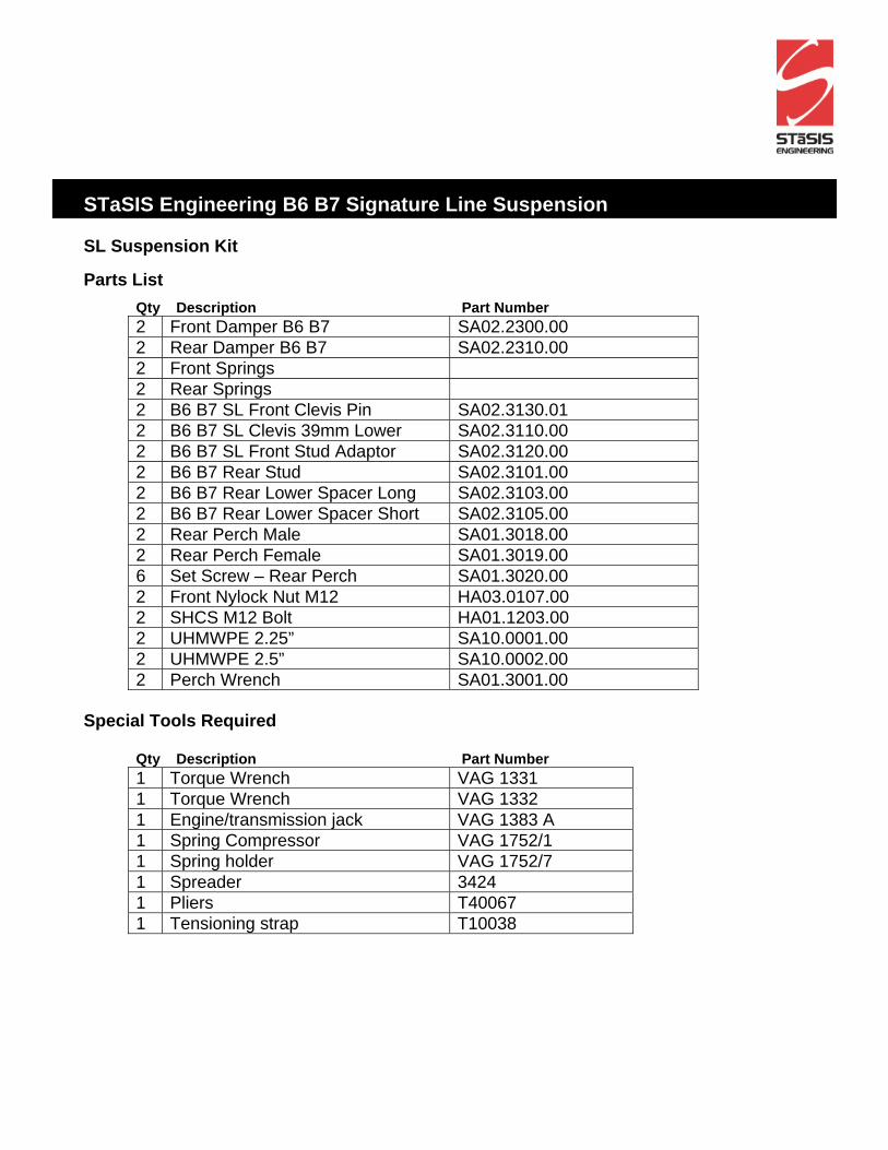
STaSIS Engineering B6 B7 Signature Line Suspension SL Suspension Kit
Parts List Qty Description Part Number 2 Front Damper B6 B7 SA02.2300.00 2 Rear Damper B6 B7 SA02.2310.00 2 Front Springs 2 Rear Springs 2 B6 B7 SL Front Clevis Pin SA02.3130.01 2 B6 B7 SL Clevis 39mm Lower SA02.3110.00 2 B6 B7 SL Front Stud Adaptor SA02.3120.00 2 B6 B7 Rear Stud SA02.3101.00 2 B6 B7 Rear Lower Spacer Long SA02.3103.00 2 B6 B7 Rear Lower Spacer Short SA02.3105.00 2 Rear Perch Male SA01.3018.00 2 Rear Perch Female SA01.3019.00 6 Set Screw – Rear Perch SA01.3020.00 2 Front Nylock Nut M12 HA03.0107.00 2 SHCS M12 Bolt HA01.1203.00 2 UHMWPE 2.25” SA10.0001.00 2 UHMWPE 2.5” SA10.0002.00 2 Perch Wrench SA01.3001.00
Special Tools Required
Qty Description Part Number 1 Torque Wrench VAG 1331 1 Torque Wrench VAG 1332 1 Engine/transmission jack VAG 1383 A 1 Spring Compressor VAG 1752/1 1 Spring holder VAG 1752/7 1 Spreader 3424 1 Pliers T40067 1 Tensioning strap T10038
2
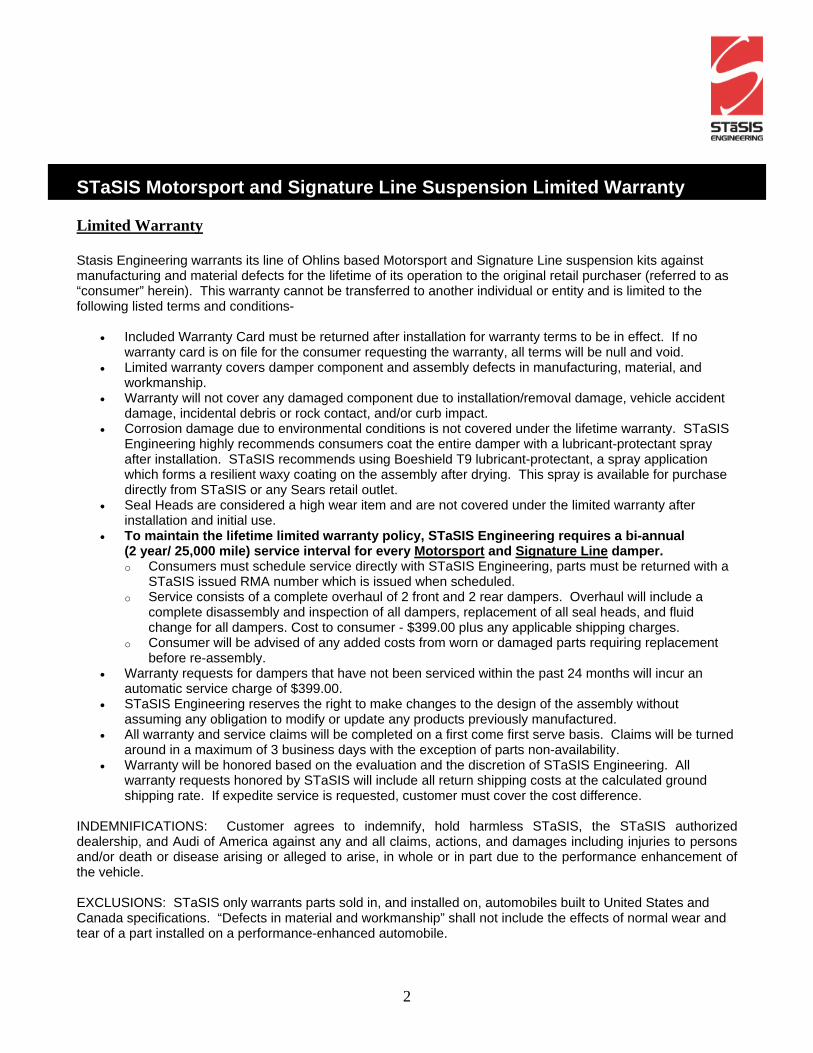
STaSIS Motorsport and Signature Line Suspension Limited Warranty Limited Warranty Stasis Engineering warrants its line of Ohlins based Motorsport and Signature Line suspension kits against manufacturing and material defects for the lifetime of its operation to the original retail purchaser (referred to as “consumer” herein). This warranty cannot be transferred to another individual or entity and is limited to the following listed terms and conditions-
• Included Warranty Card must be returned after installation for warranty terms to be in effect. If no warranty card is on file for the consumer requesting the warranty, all terms will be null and void.
• Limited warranty covers damper component and assembly defects in manufacturing, material, and workmanship.
• Warranty will not cover any damaged component due to installation/removal damage, vehicle accident damage, incidental debris or rock contact, and/or curb impact.
• Corrosion damage due to environmental conditions is not covered under the lifetime warranty. STaSIS Engineering highly recommends consumers coat the entire damper with a lubricant-protectant spray after installation. STaSIS recommends using Boeshield T9 lubricant-protectant, a spray application which forms a resilient waxy coating on the assembly after drying. This spray is available for purchase directly from STaSIS or any Sears retail outlet.
• Seal Heads are considered a high wear item and are not covered under the limited warranty after installation and initial use.
• To maintain the lifetime limited warranty policy, STaSIS Engineering requires a bi-annual (2 year/ 25,000 mile) service interval for every Motorsport and Signature Line damper. o Consumers must schedule service directly with STaSIS Engineering, parts must be returned with a
STaSIS issued RMA number which is issued when scheduled. o Service consists of a complete overhaul of 2 front and 2 rear dampers. Overhaul will include a
complete disassembly and inspection of all dampers, replacement of all seal heads, and fluid change for all dampers. Cost to consumer - $399.00 plus any applicable shipping charges.
o Consumer will be advised of any added costs from worn or damaged parts requiring replacement before re-assembly.
• Warranty requests for dampers that have not been serviced within the past 24 months will incur an automatic service charge of $399.00.
• STaSIS Engineering reserves the right to make changes to the design of the assembly without assuming any obligation to modify or update any products previously manufactured.
• All warranty and service claims will be completed on a first come first serve basis. Claims will be turned around in a maximum of 3 business days with the exception of parts non-availability.
• Warranty will be honored based on the evaluation and the discretion of STaSIS Engineering. All warranty requests honored by STaSIS will include all return shipping costs at the calculated ground shipping rate. If expedite service is requested, customer must cover the cost difference.
INDEMNIFICATIONS: Customer agrees to indemnify, hold harmless STaSIS, the STaSIS authorized dealership, and Audi of America against any and all claims, actions, and damages including injuries to persons and/or death or disease arising or alleged to arise, in whole or in part due to the performance enhancement of the vehicle. EXCLUSIONS: STaSIS only warrants parts sold in, and installed on, automobiles built to United States and Canada specifications. “Defects in material and workmanship” shall not include the effects of normal wear and tear of a part installed on a performance-enhanced automobile.
3
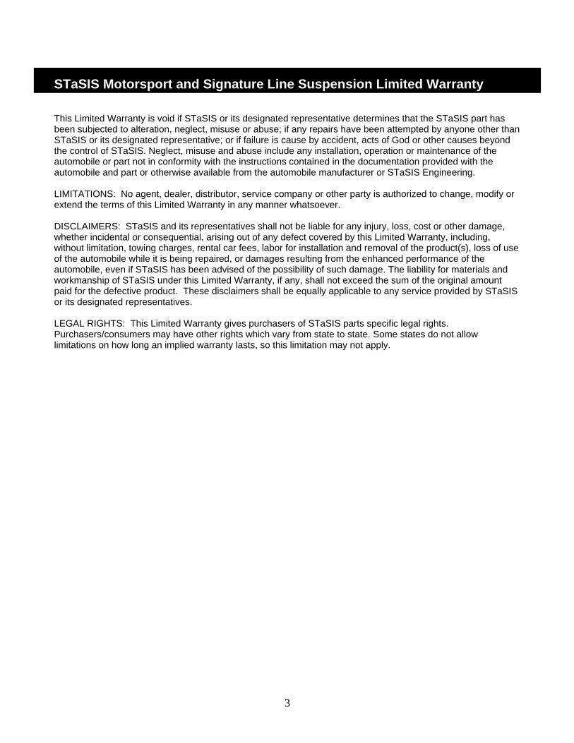
STaSIS Motorsport and Signature Line Suspension Limited Warranty This Limited Warranty is void if STaSIS or its designated representative determines that the STaSIS part has been subjected to alteration, neglect, misuse or abuse; if any repairs have been attempted by anyone other than STaSIS or its designated representative; or if failure is cause by accident, acts of God or other causes beyond the control of STaSIS. Neglect, misuse and abuse include any installation, operation or maintenance of the automobile or part not in conformity with the instructions contained in the documentation provided with the automobile and part or otherwise available from the automobile manufacturer or STaSIS Engineering. LIMITATIONS: No agent, dealer, distributor, service company or other party is authorized to change, modify or extend the terms of this Limited Warranty in any manner whatsoever. DISCLAIMERS: STaSIS and its representatives shall not be liable for any injury, loss, cost or other damage, whether incidental or consequential, arising out of any defect covered by this Limited Warranty, including, without limitation, towing charges, rental car fees, labor for installation and removal of the product(s), loss of use of the automobile while it is being repaired, or damages resulting from the enhanced performance of the automobile, even if STaSIS has been advised of the possibility of such damage. The liability for materials and workmanship of STaSIS under this Limited Warranty, if any, shall not exceed the sum of the original amount paid for the defective product. These disclaimers shall be equally applicable to any service provided by STaSIS or its designated representatives. LEGAL RIGHTS: This Limited Warranty gives purchasers of STaSIS parts specific legal rights. Purchasers/consumers may have other rights which vary from state to state. Some states do not allow limitations on how long an implied warranty lasts, so this limitation may not apply.
4
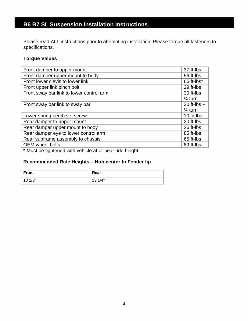
B6 B7 SL Suspension Installation Instructions Please read ALL instructions prior to attempting installation. Please torque all fasteners to specifications. Torque Values Front damper to upper mount 37 ft-lbs Front damper upper mount to body 56 ft-lbs Front lower clevis to lower link 66 ft-lbs* Front upper link pinch bolt 29 ft-lbs Front sway bar link to lower control arm 30 ft-lbs +
¼ turn Front sway bar link to sway bar 30 ft-lbs +
¼ turn Lower spring perch set screw 10 in-lbs Rear damper to upper mount 20 ft-lbs Rear damper upper mount to body 26 ft-lbs Rear damper eye to lower control arm 85 ft-lbs Rear subframe assembly to chassis 65 ft-lbs OEM wheel bolts 89 ft-lbs * Must be tightened with vehicle at or near ride height. Recommended Ride Heights – Hub center to Fender lip Front Rear
13 1/8” 13 1/4”
5
Front Removal
1 Before removing any parts, park the car on a secure, stable, and level surface. Remove wheel trim; pull trim cap off light-alloy wheels (using puller in vehicle tool kit) and loosen (but do not remove) the wheel lug nuts. Jack the vehicle up, and place the car on four stable jack stands or use a professional vehicle lift. We recommend having two people available for certain steps of the installation.
2 Remove wheels
3 Before removing left suspension strut, remove headlight range control link from track control link.
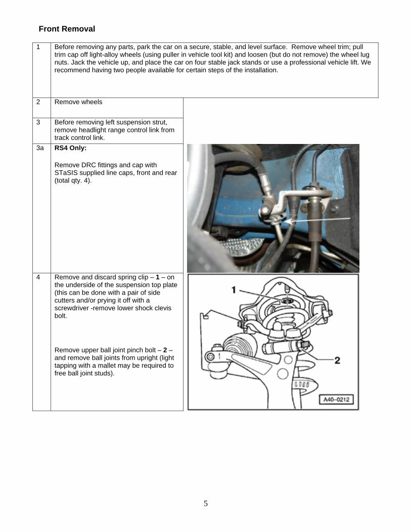
3a RS4 Only:
Remove DRC fittings and cap with STaSIS supplied line caps, front and rear (total qty. 4).
4 Remove and discard spring clip – 1 – on
the underside of the suspension top plate (this can be done with a pair of side cutters and/or prying it off with a screwdriver -remove lower shock clevis bolt.
Remove upper ball joint pinch bolt – 2 – and remove ball joints from upright (light tapping with a mallet may be required to free ball joint studs).
6
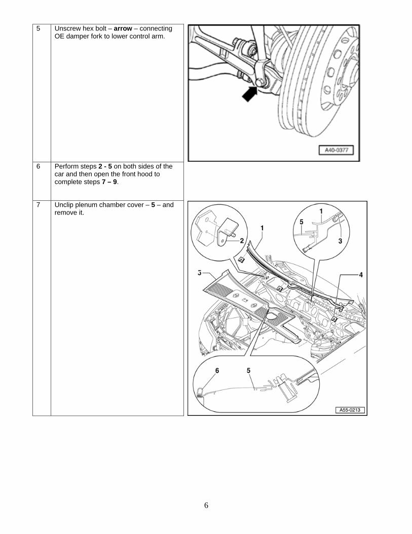
5 Unscrew hex bolt – arrow – connecting OE damper fork to lower control arm.
6 Perform steps 2 - 5 on both sides of the
car and then open the front hood to complete steps 7 – 9.
7 Unclip plenum chamber cover – 5 – and remove it.
7
8 In the engine bay, • remove rearward hood seal and rain
tray • remove retaining screw for coolant
reservoir, lift coolant reservoir out of mounting tabs at rear of tank and move slightly to the side. Disconnect level sensor plug from bottom of tank.
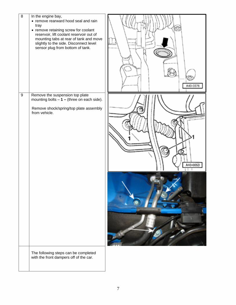
9 Remove the suspension top plate
mounting bolts – 1 – (three on each side). Remove shock/spring/top plate assembly from vehicle.
The following steps can be completed with the front dampers off of the car.
8
10 Remove OEM damper and spring from upper mount.
Use an adequate spring compressor to compress spring on shock assembly.
VAG tools are pictured here. You may also use a deep socket and vice-grips with a hex key holding the shaft in place.
Note: You will not reuse the OEM bumpstop, the thick washer, and the nylock nut that sits on top of the damper shaft.
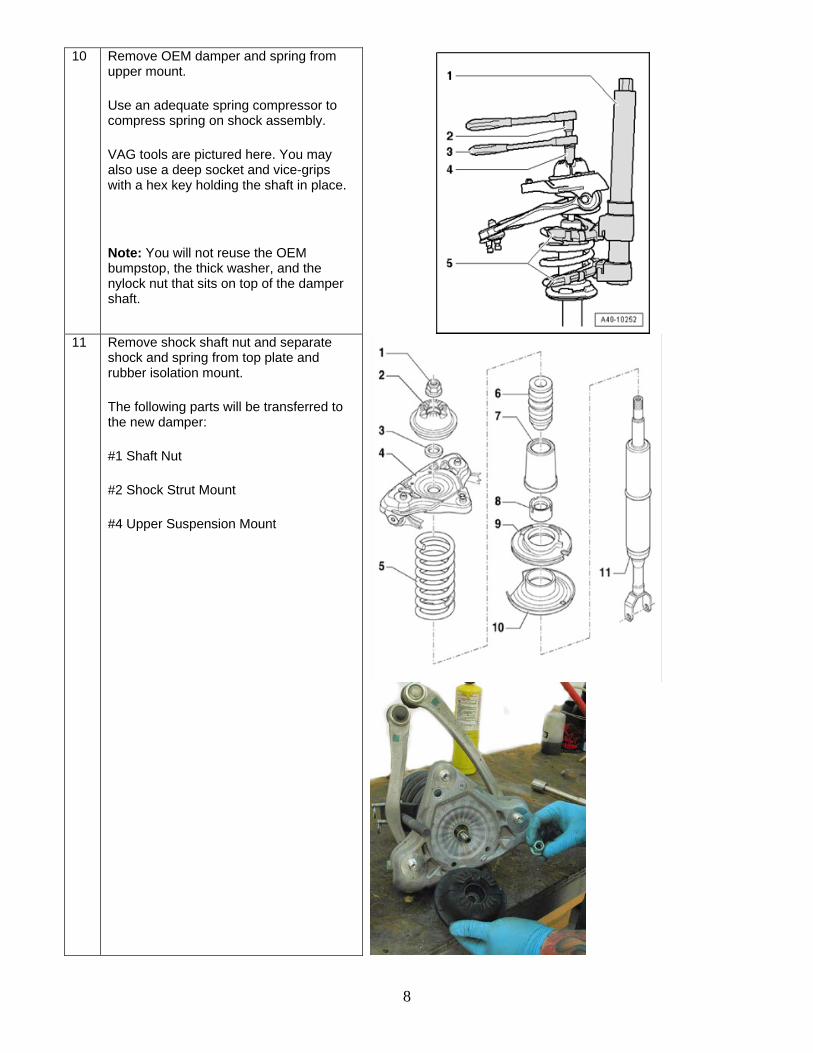
11 Remove shock shaft nut and separate shock and spring from top plate and rubber isolation mount.
The following parts will be transferred to the new damper:
#1 Shaft Nut
#2 Shock Strut Mount
#4 Upper Suspension Mount
9
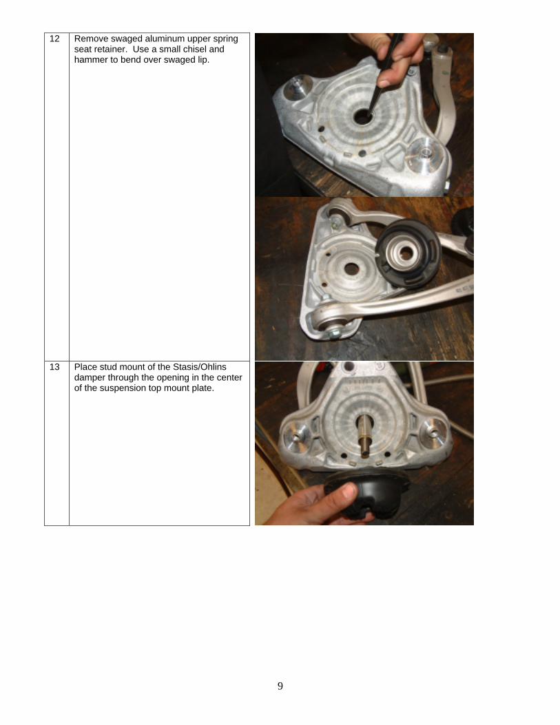
12 Remove swaged aluminum upper spring seat retainer. Use a small chisel and hammer to bend over swaged lip.
13 Place stud mount of the Stasis/Ohlins
damper through the opening in the center of the suspension top mount plate.
10
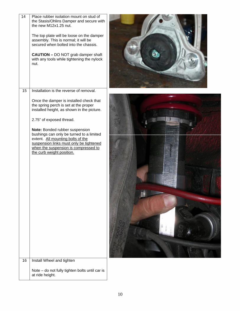
14 Place rubber isolation mount on stud of the Stasis/Ohlins Damper and secure with the new M12x1.25 nut.
The top plate will be loose on the damper assembly. This is normal; it will be secured when bolted into the chassis.
CAUTION – DO NOT grab damper shaft with any tools while tightening the nylock nut.
15 Installation is the reverse of removal.
Once the damper is installed check that the spring perch is set at the proper installed height, as shown in the picture.
2.75” of exposed thread.
Note: Bonded rubber suspension bushings can only be turned to a limited extent. All mounting bolts of the suspension links must only be tightened when the suspension is compressed to the curb weight position.
16 Install Wheel and tighten
Note – do not fully tighten bolts until car is at ride height.
11
Rear Removal
1 Securely support both rear corners of the car, relieving tension on the swaybar.
2 Remove wheels
If you have the factory spring tensioner and spring holder (VAG 1752/1 and VAG 1752/16) then move directly to Step 6 (and ignore Step 13). If you do not have the above tools then complete Steps 3 – 5 and skip Step 6.
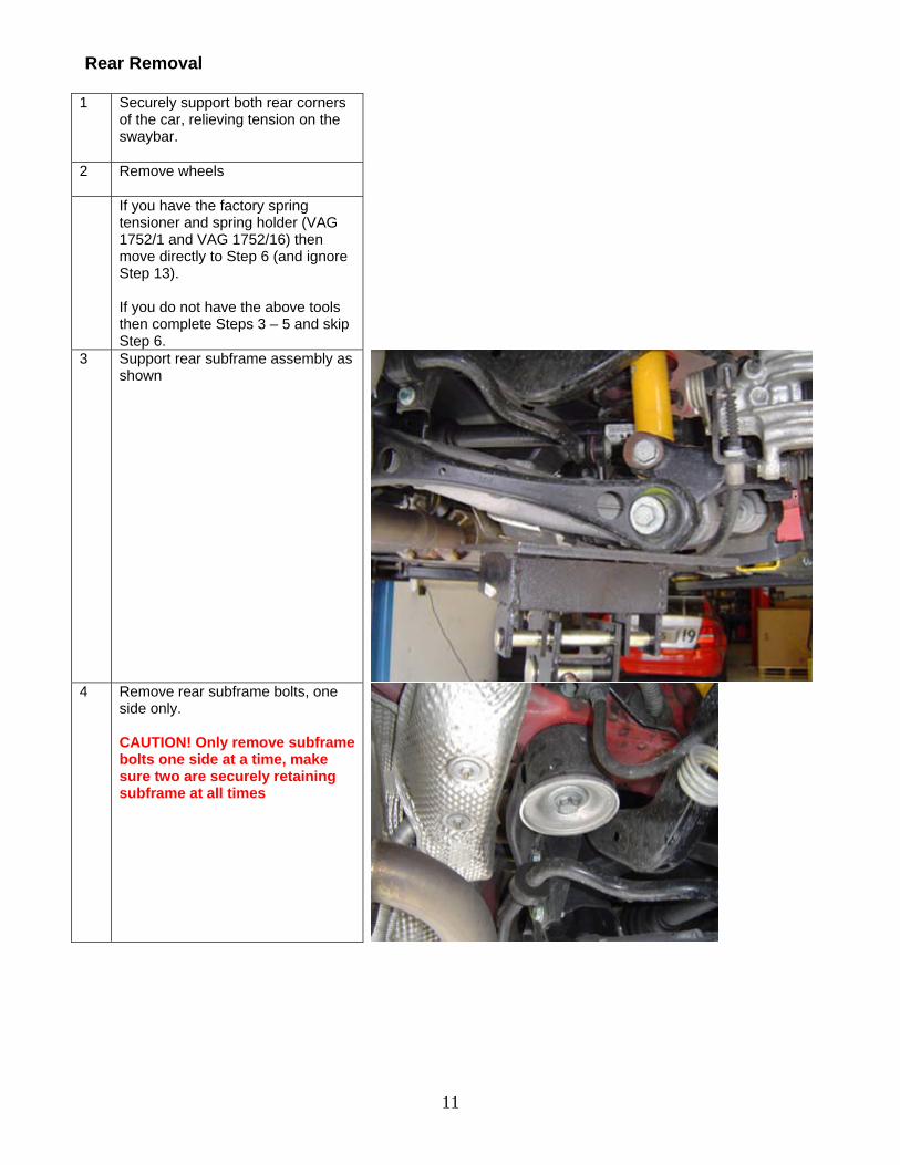
3 Support rear subframe assembly as shown
4 Remove rear subframe bolts, one
side only. CAUTION! Only remove subframe bolts one side at a time, make sure two are securely retaining subframe at all times
12
5 Gently lower rear subframe
assembly with jack.
CAUTION: if subframe is lowered too far damage to brake line may occur.
Remove rear spring and lower spring seat isolator.
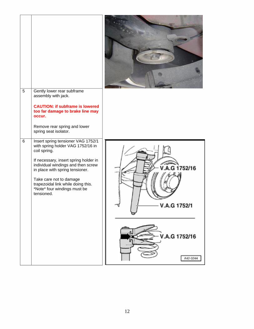
6 Insert spring tensioner VAG 1752/1 with spring holder VAG 1752/16 in coil spring. If necessary, insert spring holder in individual windings and then screw in place with spring tensioner. Take care not to damage trapezoidal link while doing this. *Note* four windings must be tensioned.
13
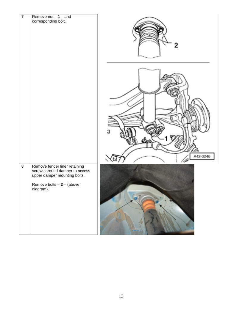
7 Remove nut – 1 – and corresponding bolt.
8 Remove fender liner retaining
screws around damper to access upper damper mounting bolts. Remove bolts – 2 – (above diagram).
14
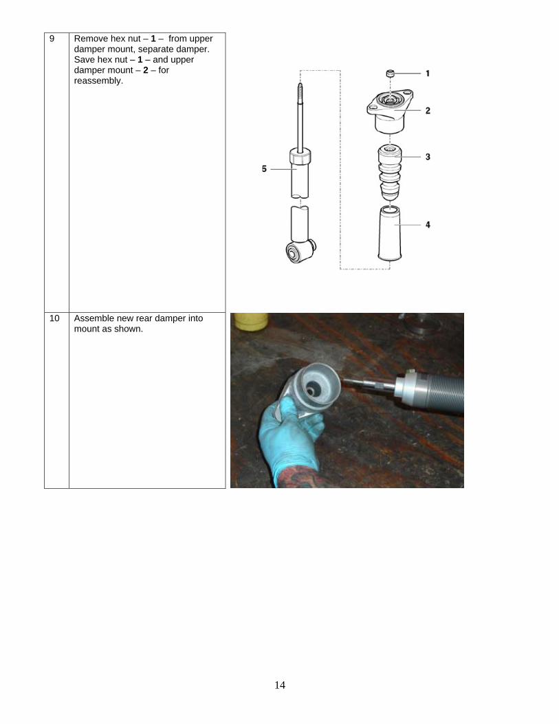
9 Remove hex nut – 1 – from upper damper mount, separate damper. Save hex nut – 1 – and upper damper mount – 2 – for reassembly.
10 Assemble new rear damper into
mount as shown.
15
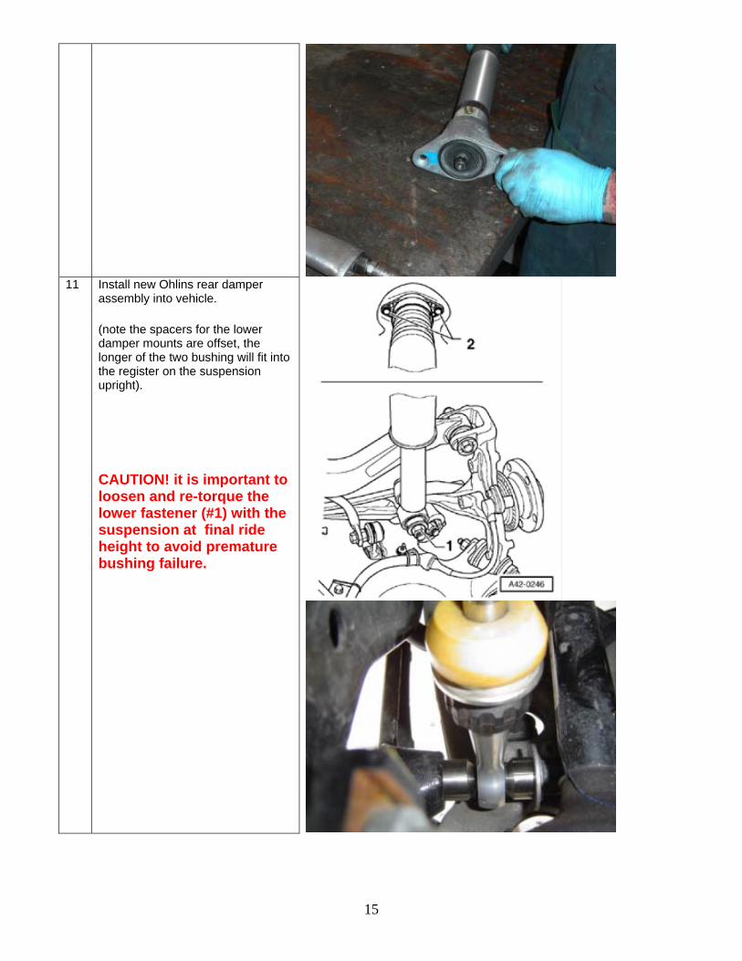
11 Install new Ohlins rear damper
assembly into vehicle.
(note the spacers for the lower damper mounts are offset, the longer of the two bushing will fit into the register on the suspension upright).
CAUTION! it is important to loosen and re-torque the lower fastener (#1) with the suspension at final ride height to avoid premature bushing failure.
16
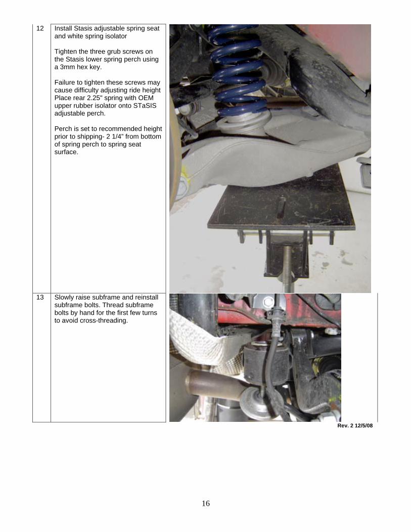
12 Install Stasis adjustable spring seat and white spring isolator Tighten the three grub screws on the Stasis lower spring perch using a 3mm hex key. Failure to tighten these screws may cause difficulty adjusting ride height Place rear 2.25" spring with OEM upper rubber isolator onto STaSIS adjustable perch. Perch is set to recommended height prior to shipping- 2 1/4” from bottom of spring perch to spring seat surface.
13 Slowly raise subframe and reinstall
subframe bolts. Thread subframe bolts by hand for the first few turns to avoid cross-threading.
Rev. 2 12/5/08

17
STaSIS Engineering
Ride Height Adjustment for STaSIS Signature Line kit
Final ride height adjustment procedure:
1. After completing installation of the kit set the vehicle on the ground and MAKE SURE IT’S ON A LEVEL SURFACE. VERY IMPORTANT!
2. Measure the ride height of the vehicle at four points for future reference. We recommend measuring
from the center of the wheels to the bottom of the fender lip. 3. If you are pleased with this ride height then you are done, save the measurements for future reference.
If not continue to step 4. 4. Calculate the difference between the actual ride height and the ride height you would like the car to sit
at for the right front wheel. For optimum handling we recommend this be done with the driver in the car and ¾ of a tank of fuel. We recommend that the distance between the center of the wheels and the bottom of the fender lip be 13 1/8 inches Front / 13 ¼ inches Rear. Below 12 5/8 inches the suspension is operating too close to its maximum bump travel and handling can be negatively impacted.
5. The ratio between shock body motion and wheel motion is about 0.7 to 1. This means that the wheel
travels about 1 inch for every 0.7 inches of shock body travel. Therefore, for example, if you wanted to lower the car ½ inch from its current ride height at the right front wheel, then you would have to lower the lower spring perch on the right front shock body by ½ x 0.7 = 0.35 inches. The rear motion ratio is slightly different.
6. Repeat steps 4 & 5 for the left front, left rear and right rear wheels. 7. Armed with the data from steps 4,5 & 6, securely jack the car up and place it on four jack stands.
Remove the wheels if necessary to reach the lower spring perches. Loosen the lower perch set screw and thread the lower perch up or down by the amount you have calculated in step 5. Record the location of the perch so you can have it as a future reference if needed. Once the desired height is attained, tighten the locking perch against the spring perch.
8. Place the wheels back on the car and lower it to the ground. Go to step 2. Make sure the car is in the
exact same location as before and press up and down on the car 3 or 4 times at each of the four wheels to settle the suspension before you make any measurements.
18
Maintenance Instructions for Signature Line Coil Over kit
Custom Valved Ohlins Threaded Aluminum Dampers Monthly maintenance: The STASIS Coil Over system is designed to provide superior service for the lifetime of your vehicle with a minimum of preventative maintenance. We recommend the following steps are performed monthly, preferably before winter season. Vehicles that are exposed to more abusive environments, such as sea salt, road salt or dirt roads may necessitate more frequent maintenance.
1. Securely support the vehicle on four jack stands and remove the road wheels. 2. Clean the threaded portion of the damper with a non metallic brush using soap and water. 3. We recommend lowering or raising the lower spring perch to allow access to clean the
threaded portion of the damper that is covered by the perches. 4. Lubricate the threaded portion of the damper with “Gewindaspray” or a similar wax based
lubricant. 5. Return the perches to their original location and tighten the locking perches.
6. Check the rear spherical bearings and verify that they are properly lubricated. If necessary,
lubricate the spherical bearings. If you have any questions about this, please call STaSIS at 707-935-9700.
Secure the road wheels and return the vehicle to the ground. Watch that the springs seat properly on the spring perches