Start-Up, Operation, and Maintenance Instructions · Manufacturer reserves the right to...
140
Manufacturer reserves the right to discontinue, or change at any time, specifications or designs without notice and without incurring obligations. PC 211 Catalog No. 531-982 Printed in U.S.A. Form 19XR-5SS Pg 1 6-01 Replaces: 19XR-4SS Book 2 Tab 5a Start-Up, Operation, and Maintenance Instructions SAFETY CONSIDERATIONS Centrifugal liquid chillers are designed to provide safe and reliable service when operated within design specifica- tions. When operating this equipment, use good judgment and safety precautions to avoid damage to equipment and property or injury to personnel. Be sure you understand and follow the procedures and safety precautions contained in the chiller instructions as well as those listed in this guide. DO NOT VENT refrigerant relief valves within a building. Outlet from rupture disc or relief valve must be vented outdoors in accor- dance with the latest edition of ANSI/ASHRAE 15 (American National Standards Institute/American Society of Heating, Refrigera- tion, and Air Conditioning Engineers). The accumulation of refriger- ant in an enclosed space can displace oxygen and cause asphyxiation. PROVIDE adequate ventilation in accordance with ANSI/ASHRAE 15, especially for enclosed and low overhead spaces. Inhalation of high concentrations of vapor is harmful and may cause heart irregular- ities, unconsciousness, or death. Misuse can be fatal. Vapor is heavier than air and reduces the amount of oxygen available for breathing. Product causes eye and skin irritation. Decomposition products are hazardous. DO NOT USE OXYGEN to purge lines or to pressurize a chiller for any purpose. Oxygen gas reacts violently with oil, grease, and other common substances. NEVER EXCEED specified test pressures, VERIFY the allowable test pressure by checking the instruction literature and the design pres- sures on the equipment nameplate. DO NOT USE air for leak testing. Use only refrigerant or dry nitrogen. DO NOT VALVE OFF any safety device. BE SURE that all pressure relief devices are properly installed and functioning before operating any chiller. RISK OF INJURY OR DEATH by electrocution. High voltage is present on motor leads even though the motor is not running when a solid-state or inside-delta mechanical starter is used. Open the power supply disconnect before touching motor leads or terminals. DO NOT WELD OR FLAMECUT any refrigerant line or vessel until all refrigerant (liquid and vapor) has been removed from chiller. Traces of vapor should be displaced with dry air or nitrogen and the work area should be well ventilated. Refrigerant in contact with an open flame produces toxic gases. DO NOT USE eyebolts or eyebolt holes to rig chiller sections or the entire assembly. DO NOT work on high-voltage equipment unless you are a qualified electrician. DO NOT WORK ON electrical components, including control pan- els, switches, starters, or oil heater until you are sure ALL POWER IS OFF and no residual voltage can leak from capacitors or solid-state components. LOCK OPEN AND TAG electrical circuits during servicing. IF WORK IS INTERRUPTED, confirm that all circuits are deenergized before resuming work. AVOID SPILLING liquid refrigerant on skin or getting it into the eyes. USE SAFETY GOGGLES. Wash any spills from the skin with soap and water. If liquid refrigerant enters the eyes, IMMEDIATELY FLUSH EYES with water and consult a physician. NEVER APPLY an open flame or live steam to a refrigerant cylinder. Dangerous over pressure can result. When it is necessary to heat refrigerant, use only warm (110 F [43 C]) water. DO NOT REUSE disposable (nonreturnable) cylinders or attempt to refill them. It is DANGEROUS AND ILLEGAL. When cylinder is emptied, evacuate remaining gas pressure, loosen the collar and unscrew and discard the valve stem. DO NOT INCINERATE. CHECK THE REFRIGERANT TYPE before adding refrigerant to the chiller. The introduction of the wrong refrigerant can cause dam- age or malfunction to this chiller. Operation of this equipment with refrigerants other than those cited herein should comply with ANSI/ASHRAE 15 (latest edition). Contact Carrier for further information on use of this chiller with other refrigerants. DO NOT ATTEMPT TO REMOVE fittings, covers, etc., while chiller is under pressure or while chiller is running. Be sure pressure is at 0 psig (0 kPa) before breaking any refrigerant connection. CAREFULLY INSPECT all relief devices, rupture discs, and other relief devices AT LEAST ONCE A YEAR. If chiller operates in a corrosive atmosphere, inspect the devices at more frequent intervals. DO NOT ATTEMPT TO REPAIR OR RECONDITION any relief device when corrosion or build-up of foreign material (rust, dirt, scale, etc.) is found within the valve body or mechanism. Replace the device. DO NOT install relief devices in series or backwards. USE CARE when working near or in line with a compressed spring. Sudden release of the spring can cause it and objects in its path to act as projectiles. DO NOT STEP on refrigerant lines. Broken lines can whip about and release refrigerant, causing personal injury. DO NOT climb over a chiller. Use platform, catwalk, or staging. Fol- low safe practices when using ladders. USE MECHANICAL EQUIPMENT (crane, hoist, etc.) to lift or move inspection covers or other heavy components. Even if compo- nents are light, use mechanical equipment when there is a risk of slip- ping or losing your balance. BE AWARE that certain automatic start arrangements CAN ENGAGE THE STARTER, TOWER FAN, OR PUMPS. Open the disconnect ahead of the starter, tower fans, or pumps. USE only repair or replacement parts that meet the code requirements of the original equipment. DO NOT VENT OR DRAIN waterboxes containing industrial brines, liquid, gases, or semisolids without the permission of your process control group. DO NOT LOOSEN waterbox cover bolts until the waterbox has been completely drained. DOUBLE-CHECK that coupling nut wrenches, dial indicators, or other items have been removed before rotating any shafts. DO NOT LOOSEN a packing gland nut before checking that the nut has a positive thread engagement. PERIODICALLY INSPECT all valves, fittings, and piping for corro- sion, rust, leaks, or damage. PROVIDE A DRAIN connection in the vent line near each pressure relief device to prevent a build-up of condensate or rain water. 19XR,XRV Hermetic Centrifugal Liquid Chillers 50/60 Hz With PIC II Controls and HFC-134a
Transcript of Start-Up, Operation, and Maintenance Instructions · Manufacturer reserves the right to...
Manufacturer reserves the right to discontinue, or change at any time, specifications or designs without notice and without incurring obligations.PC 211 Catalog No. 531-982 Printed in U.S.A. Form 19XR-5SS Pg 1 6-01 Replaces: 19XR-4SSBook 2
Tab 5a
Start-Up, Operation, and Maintenance InstructionsSAFETY CONSIDERATIONS
Centrifugal liquid chillers are designed to provide safe andreliable service when operated within design specifica-tions. When operating this equipment, use good judgmentand safety precautions to avoid damage to equipment andproperty or injury to personnel.
Be sure you understand and follow the procedures andsafety precautions contained in the chiller instructions aswell as those listed in this guide.
DO NOT VENT refrigerant relief valves within a building. Outletfrom rupture disc or relief valve must be vented outdoors in accor-dance with the latest edition of ANSI/ASHRAE 15 (AmericanNational Standards Institute/American Society of Heating, Refrigera-tion, and Air Conditioning Engineers). The accumulation of refriger-ant in an enclosed space can displace oxygen and cause asphyxiation.PROVIDE adequate ventilation in accordance with ANSI/ASHRAE15, especially for enclosed and low overhead spaces. Inhalation ofhigh concentrations of vapor is harmful and may cause heart irregular-ities, unconsciousness, or death. Misuse can be fatal. Vapor is heavierthan air and reduces the amount of oxygen available for breathing.Product causes eye and skin irritation. Decomposition products arehazardous.DO NOT USE OXYGEN to purge lines or to pressurize a chiller forany purpose. Oxygen gas reacts violently with oil, grease, and othercommon substances.NEVER EXCEED specified test pressures, VERIFY the allowabletest pressure by checking the instruction literature and the design pres-sures on the equipment nameplate.DO NOT USE air for leak testing. Use only refrigerant or drynitrogen.DO NOT VALVE OFF any safety device.BE SURE that all pressure relief devices are properly installed andfunctioning before operating any chiller.
RISK OF INJURY OR DEATH by electrocution. High voltage ispresent on motor leads even though the motor is not running when asolid-state or inside-delta mechanical starter is used. Open the powersupply disconnect before touching motor leads or terminals.
DO NOT WELD OR FLAMECUT any refrigerant line or vessel untilall refrigerant (liquid and vapor) has been removed from chiller.Traces of vapor should be displaced with dry air or nitrogen and thework area should be well ventilated. Refrigerant in contact with anopen flame produces toxic gases.DO NOT USE eyebolts or eyebolt holes to rig chiller sections or theentire assembly.DO NOT work on high-voltage equipment unless you are a qualifiedelectrician.DO NOT WORK ON electrical components, including control pan-els, switches, starters, or oil heater until you are sure ALL POWER ISOFF and no residual voltage can leak from capacitors or solid-statecomponents.LOCK OPEN AND TAG electrical circuits during servicing. IFWORK IS INTERRUPTED, confirm that all circuits are deenergizedbefore resuming work.AVOID SPILLING liquid refrigerant on skin or getting it into theeyes. USE SAFETY GOGGLES. Wash any spills from the skin with
soap and water. If liquid refrigerant enters the eyes, IMMEDIATELYFLUSH EYES with water and consult a physician.NEVER APPLY an open flame or live steam to a refrigerant cylinder.Dangerous over pressure can result. When it is necessary to heatrefrigerant, use only warm (110 F [43 C]) water.DO NOT REUSE disposable (nonreturnable) cylinders or attempt torefill them. It is DANGEROUS AND ILLEGAL. When cylinder isemptied, evacuate remaining gas pressure, loosen the collar andunscrew and discard the valve stem. DO NOT INCINERATE.CHECK THE REFRIGERANT TYPE before adding refrigerant tothe chiller. The introduction of the wrong refrigerant can cause dam-age or malfunction to this chiller.
Operation of this equipment with refrigerants other than thosecited herein should comply with ANSI/ASHRAE 15 (latest edition).Contact Carrier for further information on use of this chiller with otherrefrigerants.DO NOT ATTEMPT TO REMOVE fittings, covers, etc., whilechiller is under pressure or while chiller is running. Be sure pressure isat 0 psig (0 kPa) before breaking any refrigerant connection.CAREFULLY INSPECT all relief devices, rupture discs, and otherrelief devices AT LEAST ONCE A YEAR. If chiller operates in acorrosive atmosphere, inspect the devices at more frequent intervals.DO NOT ATTEMPT TO REPAIR OR RECONDITION any reliefdevice when corrosion or build-up of foreign material (rust, dirt, scale,etc.) is found within the valve body or mechanism. Replace thedevice.DO NOT install relief devices in series or backwards.USE CARE when working near or in line with a compressed spring.Sudden release of the spring can cause it and objects in its path to actas projectiles.
DO NOT STEP on refrigerant lines. Broken lines can whip about andrelease refrigerant, causing personal injury.DO NOT climb over a chiller. Use platform, catwalk, or staging. Fol-low safe practices when using ladders.USE MECHANICAL EQUIPMENT (crane, hoist, etc.) to lift ormove inspection covers or other heavy components. Even if compo-nents are light, use mechanical equipment when there is a risk of slip-ping or losing your balance.BE AWARE that certain automatic start arrangements CANENGAGE THE STARTER, TOWER FAN, OR PUMPS. Open thedisconnect ahead of the starter, tower fans, or pumps.USE only repair or replacement parts that meet the code requirementsof the original equipment.DO NOT VENT OR DRAIN waterboxes containing industrial brines,liquid, gases, or semisolids without the permission of your processcontrol group.DO NOT LOOSEN waterbox cover bolts until the waterbox has beencompletely drained.DOUBLE-CHECK that coupling nut wrenches, dial indicators, orother items have been removed before rotating any shafts.DO NOT LOOSEN a packing gland nut before checking that the nuthas a positive thread engagement.PERIODICALLY INSPECT all valves, fittings, and piping for corro-sion, rust, leaks, or damage.
PROVIDE A DRAIN connection in the vent line near each pressurerelief device to prevent a build-up of condensate or rain water.
19XR,XRVHermetic Centrifugal Liquid Chillers
50/60 HzWith PIC II Controls and HFC-134a
2
CONTENTS
PageSAFETY CONSIDERATIONS . . . . . . . . . . . . . . . . . . . . . . 1INTRODUCTION . . . . . . . . . . . . . . . . . . . . . . . . . . . . . . . . . . 4ABBREVIATIONS AND EXPLANATIONS . . . . . . . . 4,5CHILLER FAMILIARIZATION . . . . . . . . . . . . . . . . . . . . 5-7Chiller Information Nameplate . . . . . . . . . . . . . . . . . . . . 5System Components . . . . . . . . . . . . . . . . . . . . . . . . . . . . . 5Cooler . . . . . . . . . . . . . . . . . . . . . . . . . . . . . . . . . . . . . . . . . . . . 5Condenser . . . . . . . . . . . . . . . . . . . . . . . . . . . . . . . . . . . . . . . 5Motor-Compressor . . . . . . . . . . . . . . . . . . . . . . . . . . . . . . . 5Control Panel . . . . . . . . . . . . . . . . . . . . . . . . . . . . . . . . . . . . . 5Factory-Mounted Starter or Variable
Frequency Drive (Optional). . . . . . . . . . . . . . . . . . . . . 7Storage Vessel (Optional) . . . . . . . . . . . . . . . . . . . . . . . . 7REFRIGERATION CYCLE . . . . . . . . . . . . . . . . . . . . . . . . . 7MOTOR AND LUBRICATING OIL
COOLING CYCLE . . . . . . . . . . . . . . . . . . . . . . . . . . . . 7,8VFD COOLING CYCLE. . . . . . . . . . . . . . . . . . . . . . . . . . . . 8LUBRICATION CYCLE . . . . . . . . . . . . . . . . . . . . . . . . . . 8,9Summary . . . . . . . . . . . . . . . . . . . . . . . . . . . . . . . . . . . . . . . . . 8Details. . . . . . . . . . . . . . . . . . . . . . . . . . . . . . . . . . . . . . . . . . . . 8Oil Reclaim System. . . . . . . . . . . . . . . . . . . . . . . . . . . . . . . 8• PRIMARY OIL RECOVERY MODE• SECONDARY OIL RECOVERY METHODSTARTING EQUIPMENT . . . . . . . . . . . . . . . . . . . . . . . 9,10Unit-Mounted Solid-State Starter
(Optional) . . . . . . . . . . . . . . . . . . . . . . . . . . . . . . . . . . . . . . 9Unit-Mounted Wye-Delta Starter
(Optional) . . . . . . . . . . . . . . . . . . . . . . . . . . . . . . . . . . . . . 10Unit-Mounted VFD (Optional) . . . . . . . . . . . . . . . . . . . . 10CONTROLS. . . . . . . . . . . . . . . . . . . . . . . . . . . . . . . . . . . 10-45Definitions . . . . . . . . . . . . . . . . . . . . . . . . . . . . . . . . . . . . . . 10• ANALOG SIGNAL• DISCRETE SIGNALGeneral. . . . . . . . . . . . . . . . . . . . . . . . . . . . . . . . . . . . . . . . . . 11PIC II System Components . . . . . . . . . . . . . . . . . . . . . . 11• CHILLER VISUAL CONTROLLER (CVC)• INTERNATIONAL CHILLER VISUAL
CONTROLLER (ICVC)• INTEGRATED STARTER MODULE (ISM)• CHILLER CONTROL MODULE (CCM)• OIL HEATER CONTACTOR (1C)• OIL PUMP CONTACTOR (2C)• HOT GAS BYPASS CONTACTOR RELAY (3C)
(Optional)• CONTROL TRANSFORMERS (T1, T2)• OPTIONAL TRANSFORMER (T3)CVC/ICVC Operation and Menus. . . . . . . . . . . . . . . . . 15• GENERAL• ALARMS AND ALERTS• CVC/ICVC MENU ITEMS• BASIC CVC/ICVC OPERATIONS (Using the Softkeys)• TO VIEW STATUS• OVERRIDE OPERATIONS• TIME SCHEDULE OPERATION• TO VIEW AND CHANGE SET POINTS• SERVICE OPERATIONPIC II System Functions . . . . . . . . . . . . . . . . . . . . . . . . . 33• CAPACITY CONTROL FIXED SPEED• CAPACITY CONTROL VFD• ECW CONTROL OPTION• CONTROL POINT DEADBAND• DIFFUSER CONTROL• PROPORTIONAL BANDS AND GAIN• DEMAND LIMITING• CHILLER TIMERS• OCCUPANCY SCHEDULESafety Controls . . . . . . . . . . . . . . . . . . . . . . . . . . . . . . . . . . 34
PageShunt Trip (Option) . . . . . . . . . . . . . . . . . . . . . . . . . . . . . . 35Default Screen Freeze . . . . . . . . . . . . . . . . . . . . . . . . . . . 35Ramp Loading. . . . . . . . . . . . . . . . . . . . . . . . . . . . . . . . . . . 36Capacity Override . . . . . . . . . . . . . . . . . . . . . . . . . . . . . . . 36High Discharge Temperature Control . . . . . . . . . . . . 36Oil Sump Temperature Control . . . . . . . . . . . . . . . . . . 36Oil Cooler . . . . . . . . . . . . . . . . . . . . . . . . . . . . . . . . . . . . . . . 36Remote Start/Stop Controls . . . . . . . . . . . . . . . . . . . . . 36Spare Safety Inputs . . . . . . . . . . . . . . . . . . . . . . . . . . . . . 36Alarm (Trip) Output Contacts . . . . . . . . . . . . . . . . . . . . 37Refrigerant Leak Detector . . . . . . . . . . . . . . . . . . . . . . . 37Kilowatt Output. . . . . . . . . . . . . . . . . . . . . . . . . . . . . . . . . . 37Remote Reset of Alarms. . . . . . . . . . . . . . . . . . . . . . . . . 37Condenser Pump Control . . . . . . . . . . . . . . . . . . . . . . . 37Condenser Freeze Prevention . . . . . . . . . . . . . . . . . . . 38Evaporator Freeze Protection (ICVC Only) . . . . . . . 38Tower Fan Relay Low and High . . . . . . . . . . . . . . . . . . 38Auto. Restart After Power Failure . . . . . . . . . . . . . . . . 38Water/Brine Reset . . . . . . . . . . . . . . . . . . . . . . . . . . . . . . . 38• RESET TYPE 1• RESET TYPE 2• RESET TYPE 3Demand Limit Control Option . . . . . . . . . . . . . . . . . . . 39Surge Prevention Algorithm
(Fixed Speed Chiller) . . . . . . . . . . . . . . . . . . . . . . . . . . 39Surge Prevention Algorithm with VFD . . . . . . . . . . . 40Surge Protection VFD Units . . . . . . . . . . . . . . . . . . . . . 40Surge Protection (Fixed Speed Chiller) . . . . . . . . . . 40• HEAD PRESSURE REFERENCE OUTPUTLead/Lag Control . . . . . . . . . . . . . . . . . . . . . . . . . . . . . . . . 40• COMMON POINT SENSOR INSTALLATION• CHILLER COMMUNICATION WIRING• LEAD/LAG OPERATION• FAULTED CHILLER OPERATION• LOAD BALANCING• AUTO. RESTART AFTER POWER FAILUREIce Build Control . . . . . . . . . . . . . . . . . . . . . . . . . . . . . . . . 43• ICE BUILD INITIATION• START-UP/RECYCLE OPERATION• TEMPERATURE CONTROL DURING ICE BUILD• TERMINATION OF ICE BUILD• RETURN TO NON-ICE BUILD OPERATIONSAttach to Network Device Control . . . . . . . . . . . . . . . 44• ATTACHING TO OTHER CCN MODULESService Operation . . . . . . . . . . . . . . . . . . . . . . . . . . . . . . . 45• TO ACCESS THE SERVICE SCREENS• TO LOG OUT OF NETWORK DEVICE• HOLIDAY SCHEDULINGSTART-UP/SHUTDOWN/RECYCLE
SEQUENCE . . . . . . . . . . . . . . . . . . . . . . . . . . . . . . . . 46,47Local Start-Up . . . . . . . . . . . . . . . . . . . . . . . . . . . . . . . . . . . 46Shutdown Sequence . . . . . . . . . . . . . . . . . . . . . . . . . . . . 47Automatic Soft Stop Amps Threshold . . . . . . . . . . . 47Chilled Water Recycle Mode . . . . . . . . . . . . . . . . . . . . . 47Safety Shutdown . . . . . . . . . . . . . . . . . . . . . . . . . . . . . . . . 47BEFORE INITIAL START-UP . . . . . . . . . . . . . . . . . . 48-64Job Data Required . . . . . . . . . . . . . . . . . . . . . . . . . . . . . . 48Equipment Required . . . . . . . . . . . . . . . . . . . . . . . . . . . . 48Using the Optional Storage Tank
and Pumpout System . . . . . . . . . . . . . . . . . . . . . . . . . 48Remove Shipping Packaging . . . . . . . . . . . . . . . . . . . . 48Open Oil Circuit Valves . . . . . . . . . . . . . . . . . . . . . . . . . . 48Tighten All Gasketed Joints and
Guide Vane Shaft Packing . . . . . . . . . . . . . . . . . . . . . 48Check Chiller Tightness . . . . . . . . . . . . . . . . . . . . . . . . . 48Refrigerant Tracer . . . . . . . . . . . . . . . . . . . . . . . . . . . . . . . 48Leak Test Chiller . . . . . . . . . . . . . . . . . . . . . . . . . . . . . . . . 50Standing Vacuum Test. . . . . . . . . . . . . . . . . . . . . . . . . . . 50
3
CONTENTS (cont)Page
Chiller Dehydration . . . . . . . . . . . . . . . . . . . . . . . . . . . . . 53Inspect Water Piping . . . . . . . . . . . . . . . . . . . . . . . . . . . . 53Check Optional Pumpout Compressor
Water Piping . . . . . . . . . . . . . . . . . . . . . . . . . . . . . . . . . . 53Check Relief Valves . . . . . . . . . . . . . . . . . . . . . . . . . . . . . 53Inspect Wiring. . . . . . . . . . . . . . . . . . . . . . . . . . . . . . . . . . . 53Carrier Comfort Network Interface. . . . . . . . . . . . . . . 54Check Starter . . . . . . . . . . . . . . . . . . . . . . . . . . . . . . . . . . . 54• MECHANICAL STARTER• BENSHAW, INC. RediStart MICRO™
SOLID-STATE STARTER• VFD STARTEROil Charge. . . . . . . . . . . . . . . . . . . . . . . . . . . . . . . . . . . . . . . 55Power Up the Controls and
Check the Oil Heater . . . . . . . . . . . . . . . . . . . . . . . . . . 55• SOFTWARE VERSIONSoftware Configuration . . . . . . . . . . . . . . . . . . . . . . . . . 55Input the Design Set Points . . . . . . . . . . . . . . . . . . . . . 55Input the Local Occupied Schedule
(OCCPC01S) . . . . . . . . . . . . . . . . . . . . . . . . . . . . . . . . . . 55Input Service Configurations . . . . . . . . . . . . . . . . . . . . 55• PASSWORD• INPUT TIME AND DATE• CHANGE CVC/ICVC CONFIGURATION
IF NECESSARY• TO CHANGE THE PASSWORD• TO CHANGE THE CVC/ICVC DISPLAY FROM
ENGLISH TO METRIC UNITS• CHANGE LANGUAGE (ICVC ONLY)• MODIFY CONTROLLER IDENTIFICATION
IF NECESSARY• INPUT EQUIPMENT SERVICE PARAMETERS
IF NECESSARY• CHANGE THE BENSHAW, INC., RediStart
MICRO SOFTWARE CONFIGURATIONIF NECESSARY
• VERIFY VFD CONFIGURATION AND CHANGE PARAMETERS IF NECESSARY
• VFD CHILLER FIELD SET UP AND VERIFICATION• VFD CONTROL VERIFICATION (Non-Running)• VFD CONTROL VERIFICATION (Running)• CONFIGURE DIFFUSER CONTROL IF
NECESSARY• MODIFY EQUIPMENT CONFIGURATION
IF NECESSARYPerform a Control Test . . . . . . . . . . . . . . . . . . . . . . . . . . 62• COOLER CONDENSER PRESSURE TRANSDUCER
AND WATERSIDE FLOW DEVICE CALIBRATIONCheck Optional Pumpout System
Controls and Compressor. . . . . . . . . . . . . . . . . . . . . 63High Altitude Locations . . . . . . . . . . . . . . . . . . . . . . . . . 63Charge Refrigerant Into Chiller . . . . . . . . . . . . . . . . . . 63• CHILLER EQUALIZATION WITHOUT A
PUMPOUT UNIT• CHILLER EQUALIZATION WITH
PUMPOUT UNIT• TRIMMING REFRIGERANT CHARGEINITIAL START-UP . . . . . . . . . . . . . . . . . . . . . . . . . . . . 64-66Preparation . . . . . . . . . . . . . . . . . . . . . . . . . . . . . . . . . . . . . 64Dry Run to Test Start-Up Sequence . . . . . . . . . . . . . 65Check Motor Rotation . . . . . . . . . . . . . . . . . . . . . . . . . . . 65Check Oil Pressure and Compressor Stop . . . . . . 65To Prevent Accidental Start-Up. . . . . . . . . . . . . . . . . . 65Check Chiller Operating Condition . . . . . . . . . . . . . . 65Instruct the Customer Operator . . . . . . . . . . . . . . . . . 65• COOLER-CONDENSER• OPTIONAL PUMPOUT STORAGE TANK AND
PUMPOUT SYSTEM• MOTOR COMPRESSOR ASSEMBLY
Page• MOTOR COMPRESSOR LUBRICATION
SYSTEM• CONTROL SYSTEM• AUXILIARY EQUIPMENT• DESCRIBE CHILLER CYCLES• REVIEW MAINTENANCE• SAFETY DEVICES AND PROCEDURES• CHECK OPERATOR KNOWLEDGE• REVIEW THE START-UP, OPERATION, AND
MAINTENANCE MANUALOPERATING INSTRUCTIONS . . . . . . . . . . . . . . . . . .66,67Operator Duties . . . . . . . . . . . . . . . . . . . . . . . . . . . . . . . . . 66Prepare the Chiller for Start-Up . . . . . . . . . . . . . . . . . 66To Start the Chiller . . . . . . . . . . . . . . . . . . . . . . . . . . . . . . 66Check the Running System . . . . . . . . . . . . . . . . . . . . . 66To Stop the Chiller . . . . . . . . . . . . . . . . . . . . . . . . . . . . . . 66After Limited Shutdown . . . . . . . . . . . . . . . . . . . . . . . . . 66Preparation for Extended Shutdown . . . . . . . . . . . . 66After Extended Shutdown . . . . . . . . . . . . . . . . . . . . . . . 67Cold Weather Operation. . . . . . . . . . . . . . . . . . . . . . . . . 67Manual Guide Vane Operation . . . . . . . . . . . . . . . . . . . 67Refrigeration Log . . . . . . . . . . . . . . . . . . . . . . . . . . . . . . . 67PUMPOUT AND REFRIGERANT TRANSFER
PROCEDURES . . . . . . . . . . . . . . . . . . . . . . . . . . . . . 67-71Preparation . . . . . . . . . . . . . . . . . . . . . . . . . . . . . . . . . . . . . 67Operating the Optional Pumpout Unit . . . . . . . . . . . 67• TO READ REFRIGERANT PRESSURESChillers with Storage Tanks . . . . . . . . . . . . . . . . . . . . . 69• TRANSFER REFRIGERANT FROM
PUMPOUT STORAGE TANK TO CHILLER• TRANSFER REFRIGERANT FROM
CHILLER TO PUMPOUT STORAGE TANKChillers with Isolation Valves. . . . . . . . . . . . . . . . . . . . 70• TRANSFER ALL REFRIGERANT TO
CHILLER CONDENSER VESSEL• TRANSFER ALL REFRIGERANT TO
CHILLER COOLER VESSEL• RETURN CHILLER TO NORMAL
OPERATING CONDITIONSGENERAL MAINTENANCE . . . . . . . . . . . . . . . . . . . .71,72Refrigerant Properties . . . . . . . . . . . . . . . . . . . . . . . . . . 71Adding Refrigerant . . . . . . . . . . . . . . . . . . . . . . . . . . . . . . 71Removing Refrigerant . . . . . . . . . . . . . . . . . . . . . . . . . . . 71Adjusting the Refrigerant Charge . . . . . . . . . . . . . . . 71Refrigerant Leak Testing . . . . . . . . . . . . . . . . . . . . . . . . 71Leak Rate . . . . . . . . . . . . . . . . . . . . . . . . . . . . . . . . . . . . . . . 71Test After Service, Repair, or Major Leak . . . . . . . . 71• TESTING WITH REFRIGERANT TRACER• TESTING WITHOUT REFRIGERANT TRACER• TO PRESSURIZE WITH DRY NITROGENRepair the Leak, Retest, and Apply
Standing Vacuum Test . . . . . . . . . . . . . . . . . . . . . . . . 72Checking Guide Vane Linkage . . . . . . . . . . . . . . . . . . 72Trim Refrigerant Charge. . . . . . . . . . . . . . . . . . . . . . . . . 72WEEKLY MAINTENANCE . . . . . . . . . . . . . . . . . . . . . . . . 72Check the Lubrication System . . . . . . . . . . . . . . . . . . 72SCHEDULED MAINTENANCE . . . . . . . . . . . . . . . . 73-75Service Ontime. . . . . . . . . . . . . . . . . . . . . . . . . . . . . . . . . . 73Inspect the Control Panel . . . . . . . . . . . . . . . . . . . . . . . 73Check Safety and Operating Controls
Monthly . . . . . . . . . . . . . . . . . . . . . . . . . . . . . . . . . . . . . . . 73Changing Oil Filter . . . . . . . . . . . . . . . . . . . . . . . . . . . . . . 73Oil Specification . . . . . . . . . . . . . . . . . . . . . . . . . . . . . . . . 73Oil Changes . . . . . . . . . . . . . . . . . . . . . . . . . . . . . . . . . . . . . 73• TO CHANGE THE OILRefrigerant Filter . . . . . . . . . . . . . . . . . . . . . . . . . . . . . . . . 73Oil Reclaim Filter . . . . . . . . . . . . . . . . . . . . . . . . . . . . . . . . 73Inspect Refrigerant Float System . . . . . . . . . . . . . . . 74
4
CONTENTS (cont)
PageInspect Relief Valves and Piping. . . . . . . . . . . . . . . . . 74Compressor Bearing and Gear
Maintenance . . . . . . . . . . . . . . . . . . . . . . . . . . . . . . . . . . 74Inspect the Heat Exchanger Tubes
and Flow Devices . . . . . . . . . . . . . . . . . . . . . . . . . . . . . 74• COOLER AND FLOW DEVICES• CONDENSER AND FLOW DEVICESWater Leaks . . . . . . . . . . . . . . . . . . . . . . . . . . . . . . . . . . . . . 74Water Treatment . . . . . . . . . . . . . . . . . . . . . . . . . . . . . . . . . 75Inspect the Starting Equipment. . . . . . . . . . . . . . . . . . 75Check Pressure Transducers . . . . . . . . . . . . . . . . . . . . 75Optional Pumpout System Maintenance . . . . . . . . . 75• OPTIONAL PUMPOUT COMPRESSOR OIL
CHARGE• OPTIONAL PUMPOUT SAFETY CONTROL
SETTINGSOrdering Replacement Chiller Parts . . . . . . . . . . . . . 75TROUBLESHOOTING GUIDE . . . . . . . . . . . . . . . . 76-122Overview . . . . . . . . . . . . . . . . . . . . . . . . . . . . . . . . . . . . . . . . 76Checking Display Messages . . . . . . . . . . . . . . . . . . . . . 76Checking Temperature Sensors . . . . . . . . . . . . . . . . . 76• RESISTANCE CHECK• VOLTAGE DROP• CHECK SENSOR ACCURACY• DUAL TEMPERATURE SENSORSChecking Pressure Transducers. . . . . . . . . . . . . . . . . 76• UNITS EQUIPPED WITH CVC• UNITS EQUIPPED WITH ICVC• TRANSDUCER REPLACEMENTControl Algorithms Checkout Procedure . . . . . . . . 77Control Test . . . . . . . . . . . . . . . . . . . . . . . . . . . . . . . . . . . . . 77Control Modules. . . . . . . . . . . . . . . . . . . . . . . . . . . . . . . . . 87• RED LED (Labeled as STAT)• GREEN LED (Labeled as COM)Notes on Module Operation . . . . . . . . . . . . . . . . . . . . . 87Chiller Control Module (CCM) . . . . . . . . . . . . . . . . . . . 88• INPUTS• OUTPUTSIntegrated Starter Module . . . . . . . . . . . . . . . . . . . . . . . 88• INPUTS• OUTPUTSReplacing Defective Processor Modules . . . . . . . . 88• INSTALLATIONSolid-State Starters. . . . . . . . . . . . . . . . . . . . . . . . . . . . . . 88• TESTING SILICON CONTROL RECTIFIERS IN
BENSHAW, INC. SOLID-STATE STARTERS• SCR REMOVAL/INSTALLATIONPhysical Data. . . . . . . . . . . . . . . . . . . . . . . . . . . . . . . . . . . . 90INDEX . . . . . . . . . . . . . . . . . . . . . . . . . . . . . . . . . . . . . . 123,124INITIAL START-UP CHECKLIST FOR
19XR, XRV HERMETIC CENTRIFUGALLIQUID CHILLER . . . . . . . . . . . . . . . . . . . .CL-1 to CL-16
INTRODUCTION
Prior to initial start-up of the 19XR unit, those involved inthe start-up, operation, and maintenance should be thoroughlyfamiliar with these instructions and other necessary job data.This book is outlined to familiarize those involved in the start-up, operation and maintenance of the unit with the control sys-tem before performing start-up procedures. Procedures in thismanual are arranged in the sequence required for proper chillerstart-up and operation.
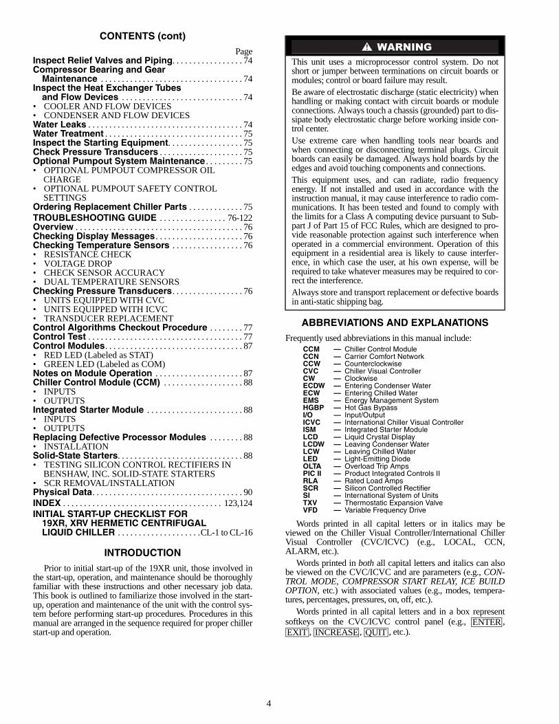
ABBREVIATIONS AND EXPLANATIONS
Frequently used abbreviations in this manual include:
Words printed in all capital letters or in italics may beviewed on the Chiller Visual Controller/International ChillerVisual Controller (CVC/ICVC) (e.g., LOCAL, CCN,ALARM, etc.).
Words printed in both all capital letters and italics can alsobe viewed on the CVC/ICVC and are parameters (e.g., CON-TROL MODE, COMPRESSOR START RELAY, ICE BUILDOPTION, etc.) with associated values (e.g., modes, tempera-tures, percentages, pressures, on, off, etc.).
Words printed in all capital letters and in a box representsoftkeys on the CVC/ICVC control panel (e.g., ,
, , , etc.).
This unit uses a microprocessor control system. Do notshort or jumper between terminations on circuit boards ormodules; control or board failure may result.Be aware of electrostatic discharge (static electricity) whenhandling or making contact with circuit boards or moduleconnections. Always touch a chassis (grounded) part to dis-sipate body electrostatic charge before working inside con-trol center.Use extreme care when handling tools near boards andwhen connecting or disconnecting terminal plugs. Circuitboards can easily be damaged. Always hold boards by theedges and avoid touching components and connections.This equipment uses, and can radiate, radio frequencyenergy. If not installed and used in accordance with theinstruction manual, it may cause interference to radio com-munications. It has been tested and found to comply withthe limits for a Class A computing device pursuant to Sub-part J of Part 15 of FCC Rules, which are designed to pro-vide reasonable protection against such interference whenoperated in a commercial environment. Operation of thisequipment in a residential area is likely to cause interfer-ence, in which case the user, at his own expense, will berequired to take whatever measures may be required to cor-rect the interference.Always store and transport replacement or defective boardsin anti-static shipping bag.
CCM — Chiller Control ModuleCCN — Carrier Comfort NetworkCCW — CounterclockwiseCVC — Chiller Visual ControllerCW — ClockwiseECDW — Entering Condenser WaterECW — Entering Chilled WaterEMS — Energy Management SystemHGBP — Hot Gas BypassI/O — Input/OutputICVC — International Chiller Visual ControllerISM — Integrated Starter ModuleLCD — Liquid Crystal DisplayLCDW — Leaving Condenser WaterLCW — Leaving Chilled WaterLED — Light-Emitting DiodeOLTA — Overload Trip AmpsPIC II — Product Integrated Controls IIRLA — Rated Load AmpsSCR — Silicon Controlled RectifierSI — International System of UnitsTXV — Thermostatic Expansion ValveVFD — Variable Frequency Drive
ENTEREXIT INCREASE QUIT
5
Factory-installed additional components are referred to asoptions in this manual; factory-supplied but field-installed ad-ditional components are referred to as accessories.
The chiller software part number of the 19XR unit is locatedon the back of the CVC/ICVC.
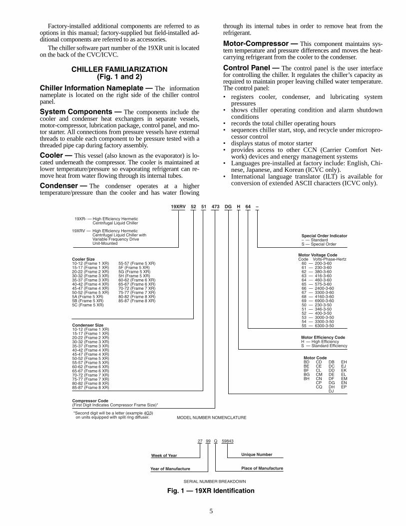
CHILLER FAMILIARIZATION(Fig. 1 and 2)
Chiller Information Nameplate — The informationnameplate is located on the right side of the chiller controlpanel.
System Components — The components include thecooler and condenser heat exchangers in separate vessels,motor-compressor, lubrication package, control panel, and mo-tor starter. All connections from pressure vessels have externalthreads to enable each component to be pressure tested with athreaded pipe cap during factory assembly.
Cooler — This vessel (also known as the evaporator) is lo-cated underneath the compressor. The cooler is maintained atlower temperature/pressure so evaporating refrigerant can re-move heat from water flowing through its internal tubes.
Condenser — The condenser operates at a highertemperature/pressure than the cooler and has water flowing
through its internal tubes in order to remove heat from therefrigerant.
Motor-Compressor — This component maintains sys-tem temperature and pressure differences and moves the heat-carrying refrigerant from the cooler to the condenser.
Control Panel — The control panel is the user interfacefor controlling the chiller. It regulates the chiller’s capacity asrequired to maintain proper leaving chilled water temperature.The control panel:• registers cooler, condenser, and lubricating system
pressures• shows chiller operating condition and alarm shutdown
conditions• records the total chiller operating hours• sequences chiller start, stop, and recycle under micropro-
cessor control• displays status of motor starter• provides access to other CCN (Carrier Comfort Net-
work) devices and energy management systems• Languages pre-installed at factory include: English, Chi-
nese, Japanese, and Korean (ICVC only).• International language translator (ILT) is available for
conversion of extended ASCII characters (ICVC only).
19XRV 52 51 473 DG H 64 –
19XR- — High Efficiency HermeticCentrifugal Liquid Chiller
19XRV — High Efficiency HermeticCentrifugal Liquid Chiller withVariable Frequency DriveUnit-Mounted
Condenser Size10-12 (Frame 1 XR)15-17 (Frame 1 XR)20-22 (Frame 2 XR)30-32 (Frame 3 XR)35-37 (Frame 3 XR)40-42 (Frame 4 XR)45-47 (Frame 4 XR)50-52 (Frame 5 XR)55-57 (Frame 5 XR)60-62 (Frame 6 XR)65-67 (Frame 6 XR)70-72 (Frame 7 XR)75-77 (Frame 7 XR)80-82 (Frame 8 XR)85-87 (Frame 8 XR)
Special Order Indicator– — StandardS — Special Order
Motor Voltage CodeCode Volts-Phase-Hertz
60 — 200-3-6061 — 230-3-6062 — 380-3-6063 — 416-3-6064 — 460-3-6065 — 575-3-6066 — 2400-3-6067 — 3300-3-6068 — 4160-3-6069 — 6900-3-6050 — 230-3-5051 — 346-3-5052 — 400-3-5053 — 3000-3-5054 — 3300-3-5055 — 6300-3-50
Compressor Code(First Digit Indicates Compressor Frame Size)*
Motor Efficiency CodeH — High EfficiencyS — Standard Efficiency
Motor CodeBD CD DB EHBE CE DC EJBF CL DD EKBG CM DE ELBH CN DF EM
CP DG ENCQ DH EP
DJ
27 99 Q 59843
Week of Year
Year of Manufacture
Unique Number
Place of Manufacture
MODEL NUMBER NOMENCLATURE
SERIAL NUMBER BREAKDOWN
Cooler Size10-12 (Frame 1 XR)15-17 (Frame 1 XR)20-22 (Frame 2 XR)30-32 (Frame 3 XR)35-37 (Frame 3 XR)40-42 (Frame 4 XR)45-47 (Frame 4 XR)50-52 (Frame 5 XR)5A (Frame 5 XR)5B (Frame 5 XR)5C (Frame 5 XR)
55-57 (Frame 5 XR)5F (Frame 5 XR)5G (Frame 5 XR)5H (Frame 5 XR)60-62 (Frame 6 XR)65-67 (Frame 6 XR)70-72 (Frame 7 XR)75-77 (Frame 7 XR)80-82 (Frame 8 XR)85-87 (Frame 8 XR)
*Second digit will be a letter (example 4G3) on units equipped with split ring diffuser.
Fig. 1 — 19XR Identification
6
34
18 19 20 21 22
23
31 30 29 28 27 26 25 2432
33 24
1
23
5
6
4
11
1213
16
15 14
17
7
910
8
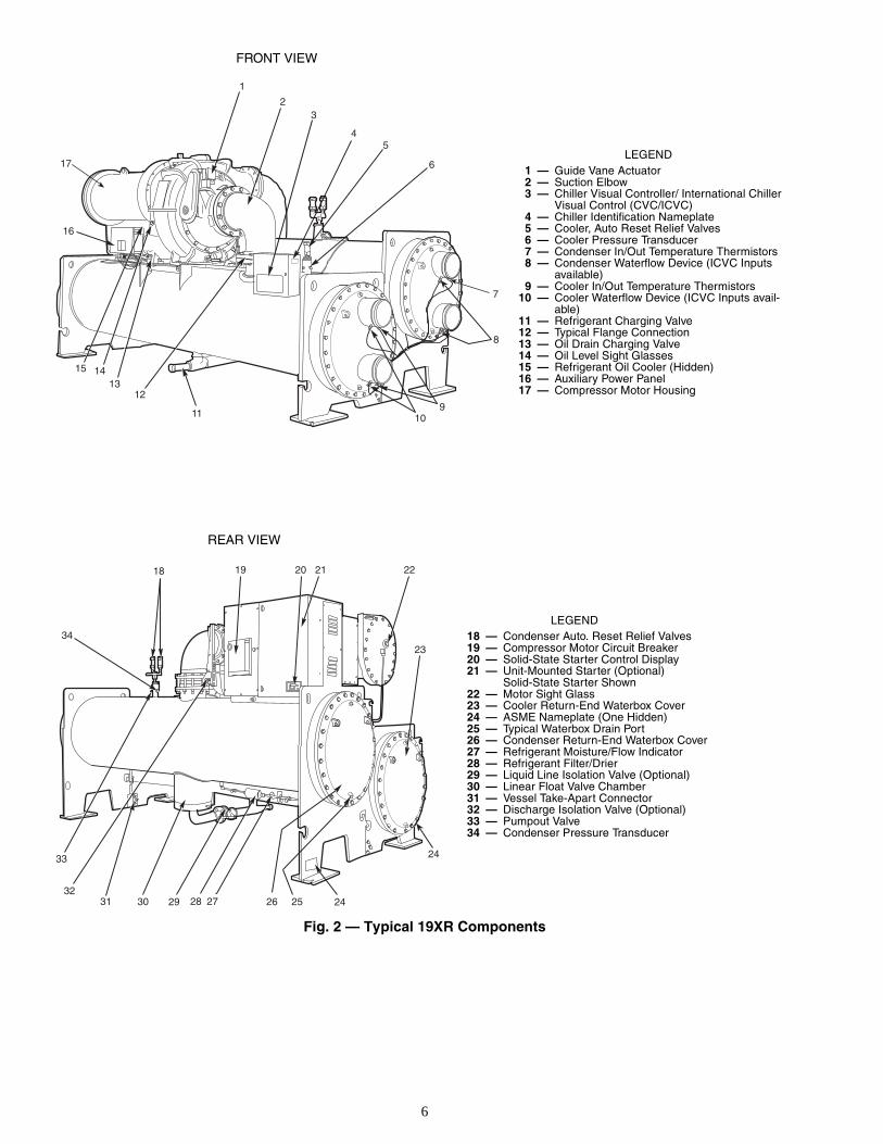
Fig. 2 — Typical 19XR Components
LEGEND1 — Guide Vane Actuator2 — Suction Elbow3 — Chiller Visual Controller/ International Chiller
Visual Control (CVC/ICVC)4 — Chiller Identification Nameplate5 — Cooler, Auto Reset Relief Valves6 — Cooler Pressure Transducer7 — Condenser In/Out Temperature Thermistors8 — Condenser Waterflow Device (ICVC Inputs
available)9 — Cooler In/Out Temperature Thermistors
10 — Cooler Waterflow Device (ICVC Inputs avail-able)
11 — Refrigerant Charging Valve12 — Typical Flange Connection13 — Oil Drain Charging Valve14 — Oil Level Sight Glasses15 — Refrigerant Oil Cooler (Hidden)16 — Auxiliary Power Panel17 — Compressor Motor Housing
LEGEND18 — Condenser Auto. Reset Relief Valves19 — Compressor Motor Circuit Breaker20 — Solid-State Starter Control Display21 — Unit-Mounted Starter (Optional)
Solid-State Starter Shown22 — Motor Sight Glass23 — Cooler Return-End Waterbox Cover24 — ASME Nameplate (One Hidden)25 — Typical Waterbox Drain Port26 — Condenser Return-End Waterbox Cover27 — Refrigerant Moisture/Flow Indicator28 — Refrigerant Filter/Drier29 — Liquid Line Isolation Valve (Optional)30 — Linear Float Valve Chamber31 — Vessel Take-Apart Connector32 — Discharge Isolation Valve (Optional)33 — Pumpout Valve34 — Condenser Pressure Transducer
REAR VIEW
FRONT VIEW
7
Factory-Mounted Starter or Variable Fre-quency Drive (Optional) — The starter allows for theproper start and disconnect of electrical energy for the com-pressor-motor, oil pump, oil heater, and control panel.
Storage Vessel (Optional) — There are 2 sizes ofstorage vessels available. The vessels have double relief valves,a magnetically-coupled dial-type refrigerant level gage, aone-inch FPT drain valve, and a 1/2-in. male flare vapor con-nection for the pumpout unit. NOTE: If a storage vessel is not used at the jobsite, factory-installed isolation valves on the chiller may be used to isolatethe chiller charge in either the cooler or condenser. An optionalpumpout system is used to transfer refrigerant from vessel tovessel.
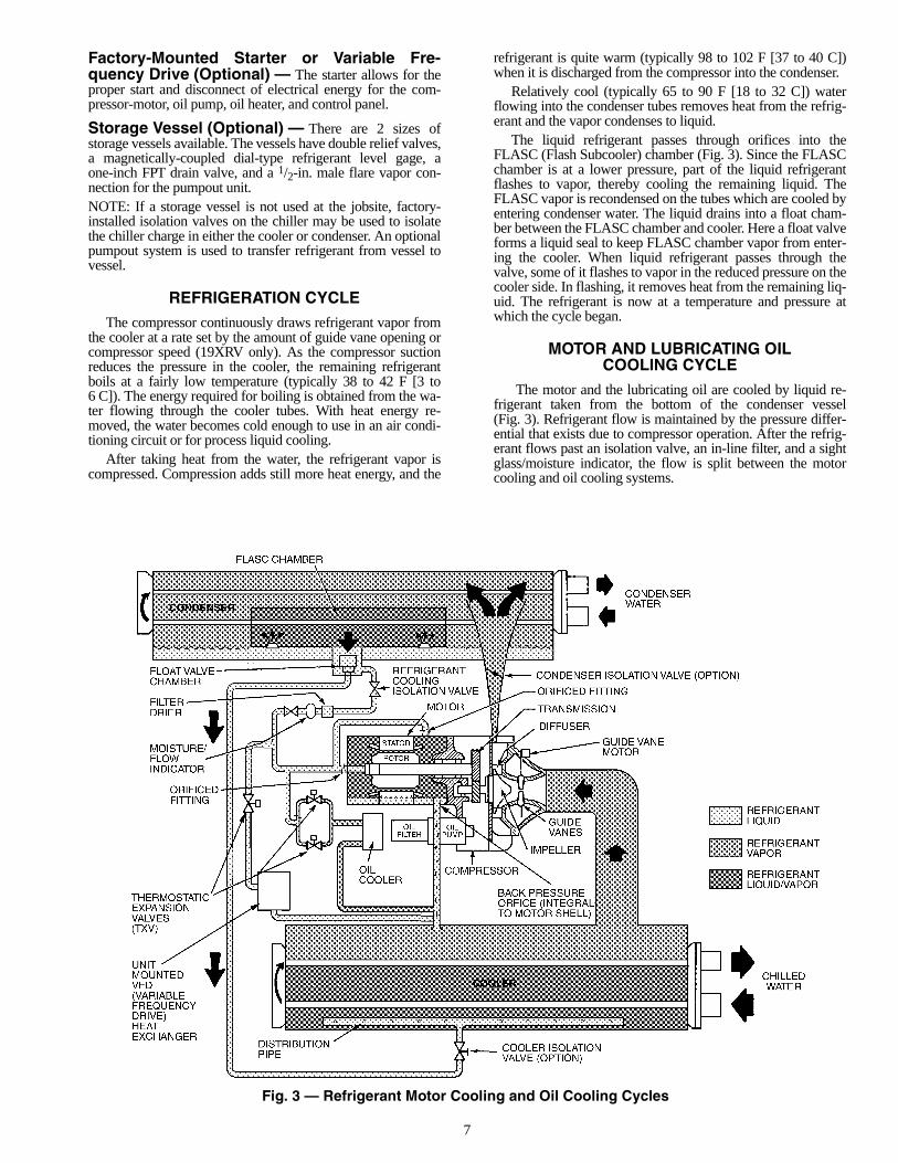
REFRIGERATION CYCLE
The compressor continuously draws refrigerant vapor fromthe cooler at a rate set by the amount of guide vane opening orcompressor speed (19XRV only). As the compressor suctionreduces the pressure in the cooler, the remaining refrigerantboils at a fairly low temperature (typically 38 to 42 F [3 to6 C]). The energy required for boiling is obtained from the wa-ter flowing through the cooler tubes. With heat energy re-moved, the water becomes cold enough to use in an air condi-tioning circuit or for process liquid cooling.
After taking heat from the water, the refrigerant vapor iscompressed. Compression adds still more heat energy, and the
refrigerant is quite warm (typically 98 to 102 F [37 to 40 C])when it is discharged from the compressor into the condenser.
Relatively cool (typically 65 to 90 F [18 to 32 C]) waterflowing into the condenser tubes removes heat from the refrig-erant and the vapor condenses to liquid.
The liquid refrigerant passes through orifices into theFLASC (Flash Subcooler) chamber (Fig. 3). Since the FLASCchamber is at a lower pressure, part of the liquid refrigerantflashes to vapor, thereby cooling the remaining liquid. TheFLASC vapor is recondensed on the tubes which are cooled byentering condenser water. The liquid drains into a float cham-ber between the FLASC chamber and cooler. Here a float valveforms a liquid seal to keep FLASC chamber vapor from enter-ing the cooler. When liquid refrigerant passes through thevalve, some of it flashes to vapor in the reduced pressure on thecooler side. In flashing, it removes heat from the remaining liq-uid. The refrigerant is now at a temperature and pressure atwhich the cycle began.
MOTOR AND LUBRICATING OILCOOLING CYCLE
The motor and the lubricating oil are cooled by liquid re-frigerant taken from the bottom of the condenser vessel(Fig. 3). Refrigerant flow is maintained by the pressure differ-ential that exists due to compressor operation. After the refrig-erant flows past an isolation valve, an in-line filter, and a sightglass/moisture indicator, the flow is split between the motorcooling and oil cooling systems.
Fig. 3 — Refrigerant Motor Cooling and Oil Cooling Cycles
8
Flow to the motor cooling system passes through an orificeand into the motor. Once past the orifice, the refrigerant isdirected over the motor by a spray nozzle. The refrigerantcollects in the bottom of the motor casing and is then drainedback into the cooler through the motor refrigerant drain line.An orifice (in the motor shell) maintains a higher pressure inthe motor shell than in the cooler. The motor is protected by atemperature sensor imbedded in the stator windings. Anincrease in motor winding temperature past the motor overrideset point overrides the temperature capacity control to hold,and if the motor temperature rises 10° F (5.5° C) above this setpoint, closes the inlet guide vanes. If the temperature risesabove the safety limit, the compressor shuts down.
Refrigerant that flows to the oil cooling system is regulatedby thermostatic expansion valves (TXVs). The TXVs regulateflow into the oil/refrigerant plate and frame-type heat exchang-er (the oil cooler in Fig. 3). The expansion valve bulbs controloil temperature to the bearings. The refrigerant leaving the oilcooler heat exchanger returns to the chiller cooler.
VFD COOLING CYCLE
The unit-mounted variable frequency drive (VFD) is cooledin a manner similar to the motor and lubricating oil coolingcycle (Fig. 3).
If equipped with a unit-mounted VFD, the refrigerant linethat feeds the motor cooling and oil cooler also feeds the heatexchanger on the unit-mounted VFD. Refrigerant is meteredthrough a thermostatic expansion valve (TXV). To maintainproper operating temperature in the VFD, the TXV bulb ismounted to the heat exchanger to regulate the flow of refriger-ant. The refrigerant leaving the heat exchanger returns to thecooler.
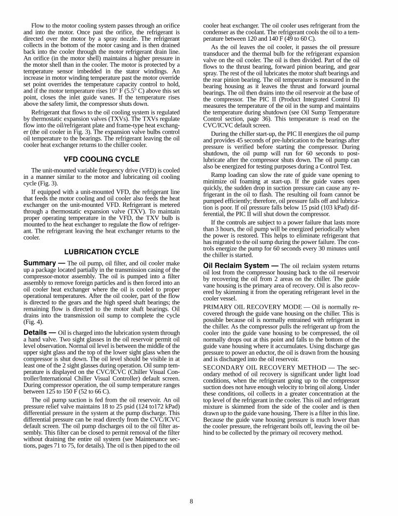
LUBRICATION CYCLE
Summary — The oil pump, oil filter, and oil cooler makeup a package located partially in the transmission casing of thecompressor-motor assembly. The oil is pumped into a filterassembly to remove foreign particles and is then forced into anoil cooler heat exchanger where the oil is cooled to properoperational temperatures. After the oil cooler, part of the flowis directed to the gears and the high speed shaft bearings; theremaining flow is directed to the motor shaft bearings. Oildrains into the transmission oil sump to complete the cycle(Fig. 4).
Details — Oil is charged into the lubrication system througha hand valve. Two sight glasses in the oil reservoir permit oillevel observation. Normal oil level is between the middle of theupper sight glass and the top of the lower sight glass when thecompressor is shut down. The oil level should be visible in atleast one of the 2 sight glasses during operation. Oil sump tem-perature is displayed on the CVC/ICVC (Chiller Visual Con-troller/International Chiller Visual Controller) default screen.During compressor operation, the oil sump temperature rangesbetween 125 to 150 F (52 to 66 C).
The oil pump suction is fed from the oil reservoir. An oilpressure relief valve maintains 18 to 25 psid (124 to172 kPad)differential pressure in the system at the pump discharge. Thisdifferential pressure can be read directly from the CVC/ICVCdefault screen. The oil pump discharges oil to the oil filter as-sembly. This filter can be closed to permit removal of the filterwithout draining the entire oil system (see Maintenance sec-tions, pages 71 to 75, for details). The oil is then piped to the oil
cooler heat exchanger. The oil cooler uses refrigerant from thecondenser as the coolant. The refrigerant cools the oil to a tem-perature between 120 and 140 F (49 to 60 C).
As the oil leaves the oil cooler, it passes the oil pressuretransducer and the thermal bulb for the refrigerant expansionvalve on the oil cooler. The oil is then divided. Part of the oilflows to the thrust bearing, forward pinion bearing, and gearspray. The rest of the oil lubricates the motor shaft bearings andthe rear pinion bearing. The oil temperature is measured in thebearing housing as it leaves the thrust and forward journalbearings. The oil then drains into the oil reservoir at the base ofthe compressor. The PIC II (Product Integrated Control II)measures the temperature of the oil in the sump and maintainsthe temperature during shutdown (see Oil Sump TemperatureControl section, page 36). This temperature is read on theCVC/ICVC default screen.
During the chiller start-up, the PIC II energizes the oil pumpand provides 45 seconds of pre-lubrication to the bearings afterpressure is verified before starting the compressor. Duringshutdown, the oil pump will run for 60 seconds to post-lubricate after the compressor shuts down. The oil pump canalso be energized for testing purposes during a Control Test.
Ramp loading can slow the rate of guide vane opening tominimize oil foaming at start-up. If the guide vanes openquickly, the sudden drop in suction pressure can cause any re-frigerant in the oil to flash. The resulting oil foam cannot bepumped efficiently; therefore, oil pressure falls off and lubrica-tion is poor. If oil pressure falls below 15 psid (103 kPad) dif-ferential, the PIC II will shut down the compressor.
If the controls are subject to a power failure that lasts morethan 3 hours, the oil pump will be energized periodically whenthe power is restored. This helps to eliminate refrigerant thathas migrated to the oil sump during the power failure. The con-trols energize the pump for 60 seconds every 30 minutes untilthe chiller is started.
Oil Reclaim System — The oil reclaim system returnsoil lost from the compressor housing back to the oil reservoirby recovering the oil from 2 areas on the chiller. The guidevane housing is the primary area of recovery. Oil is also recov-ered by skimming it from the operating refrigerant level in thecooler vessel.PRIMARY OIL RECOVERY MODE — Oil is normally re-covered through the guide vane housing on the chiller. This ispossible because oil is normally entrained with refrigerant inthe chiller. As the compressor pulls the refrigerant up from thecooler into the guide vane housing to be compressed, the oilnormally drops out at this point and falls to the bottom of theguide vane housing where it accumulates. Using discharge gaspressure to power an eductor, the oil is drawn from the housingand is discharged into the oil reservoir.SECONDARY OIL RECOVERY METHOD — The sec-ondary method of oil recovery is significant under light loadconditions, when the refrigerant going up to the compressorsuction does not have enough velocity to bring oil along. Underthese conditions, oil collects in a greater concentration at thetop level of the refrigerant in the cooler. This oil and refrigerantmixture is skimmed from the side of the cooler and is thendrawn up to the guide vane housing. There is a filter in this line.Because the guide vane housing pressure is much lower thanthe cooler pressure, the refrigerant boils off, leaving the oil be-hind to be collected by the primary oil recovery method.
9
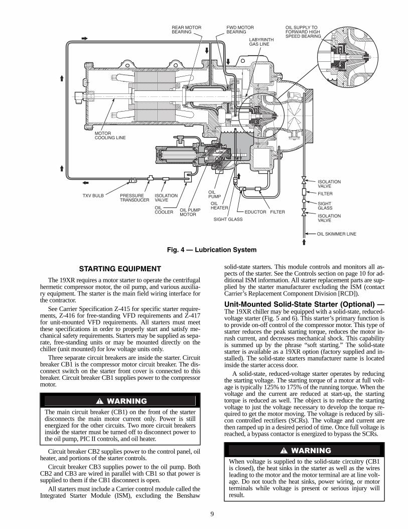
STARTING EQUIPMENT
The 19XR requires a motor starter to operate the centrifugalhermetic compressor motor, the oil pump, and various auxilia-ry equipment. The starter is the main field wiring interface forthe contractor.
See Carrier Specification Z-415 for specific starter require-ments, Z-416 for free-standing VFD requirements and Z-417for unit-mounted VFD requirements. All starters must meetthese specifications in order to properly start and satisfy me-chanical safety requirements. Starters may be supplied as sepa-rate, free-standing units or may be mounted directly on thechiller (unit mounted) for low voltage units only.
Three separate circuit breakers are inside the starter. Circuitbreaker CB1 is the compressor motor circuit breaker. The dis-connect switch on the starter front cover is connected to thisbreaker. Circuit breaker CB1 supplies power to the compressormotor.
Circuit breaker CB2 supplies power to the control panel, oilheater, and portions of the starter controls.
Circuit breaker CB3 supplies power to the oil pump. BothCB2 and CB3 are wired in parallel with CB1 so that power issupplied to them if the CB1 disconnect is open.
All starters must include a Carrier control module called theIntegrated Starter Module (ISM), excluding the Benshaw
solid-state starters. This module controls and monitors all as-pects of the starter. See the Controls section on page 10 for ad-ditional ISM information. All starter replacement parts are sup-plied by the starter manufacturer excluding the ISM (contactCarrier’s Replacement Component Division [RCD]).
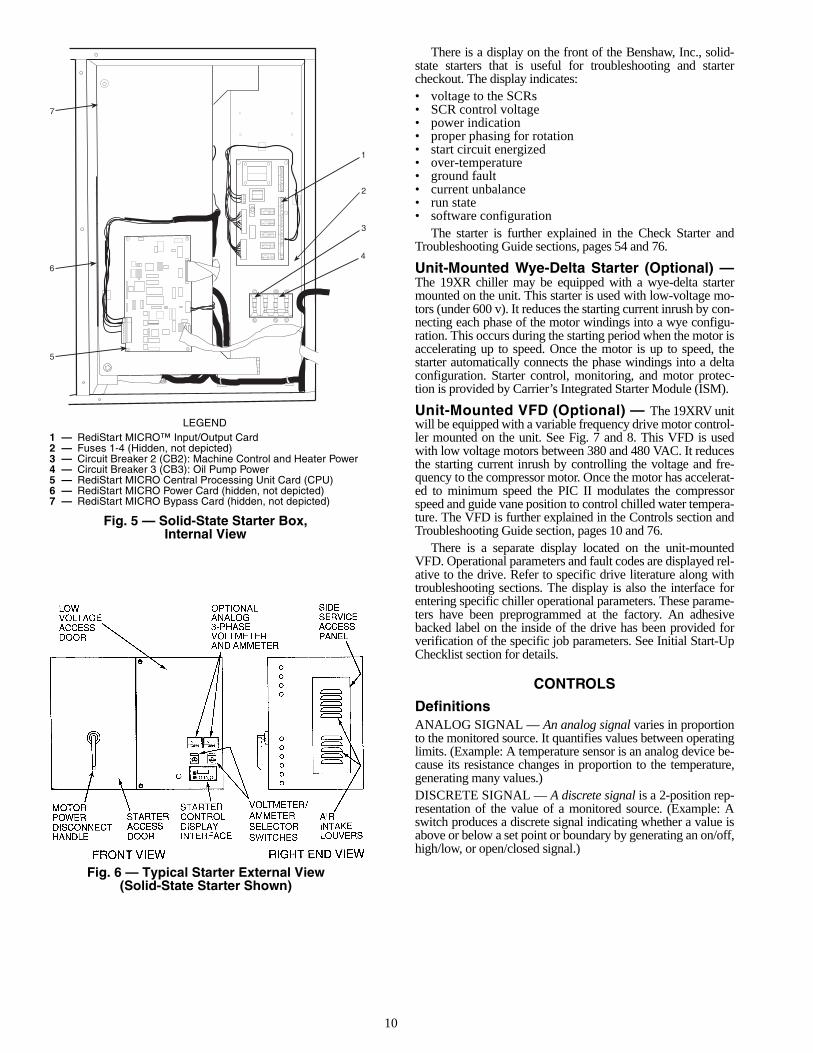
Unit-Mounted Solid-State Starter (Optional) —The 19XR chiller may be equipped with a solid-state, reduced-voltage starter (Fig. 5 and 6). This starter’s primary function isto provide on-off control of the compressor motor. This type ofstarter reduces the peak starting torque, reduces the motor in-rush current, and decreases mechanical shock. This capabilityis summed up by the phrase “soft starting.” The solid-statestarter is available as a 19XR option (factory supplied and in-stalled). The solid-state starters manufacturer name is locatedinside the starter access door.
A solid-state, reduced-voltage starter operates by reducingthe starting voltage. The starting torque of a motor at full volt-age is typically 125% to 175% of the running torque. When thevoltage and the current are reduced at start-up, the startingtorque is reduced as well. The object is to reduce the startingvoltage to just the voltage necessary to develop the torque re-quired to get the motor moving. The voltage is reduced by sili-con controlled rectifiers (SCRs). The voltage and current arethen ramped up in a desired period of time. Once full voltage isreached, a bypass contactor is energized to bypass the SCRs.
The main circuit breaker (CB1) on the front of the starterdisconnects the main motor current only. Power is stillenergized for the other circuits. Two more circuit breakersinside the starter must be turned off to disconnect power tothe oil pump, PIC II controls, and oil heater.
When voltage is supplied to the solid-state circuitry (CB1is closed), the heat sinks in the starter as well as the wiresleading to the motor and the motor terminal are at line volt-age. Do not touch the heat sinks, power wiring, or motorterminals while voltage is present or serious injury willresult.
REAR MOTORBEARING
ISOLATIONVALVE
SIGHTGLASS
FILTER
ISOLATIONVALVE
FILTEREDUCTOR
OILPUMPTXV BULB PRESSURE
TRANSDUCERISOLATIONVALVE
OILCOOLER OIL PUMP
MOTOR
OILHEATER
MOTORCOOLING LINE
LABYRINTHGAS LINE
FWD MOTORBEARING
OIL SUPPLY TOFORWARD HIGHSPEED BEARING
SIGHT GLASS
OIL SKIMMER LINE
Fig. 4 — Lubrication System
10
There is a display on the front of the Benshaw, Inc., solid-state starters that is useful for troubleshooting and startercheckout. The display indicates:• voltage to the SCRs• SCR control voltage• power indication• proper phasing for rotation• start circuit energized• over-temperature• ground fault• current unbalance• run state• software configuration
The starter is further explained in the Check Starter andTroubleshooting Guide sections, pages 54 and 76.
Unit-Mounted Wye-Delta Starter (Optional) —The 19XR chiller may be equipped with a wye-delta startermounted on the unit. This starter is used with low-voltage mo-tors (under 600 v). It reduces the starting current inrush by con-necting each phase of the motor windings into a wye configu-ration. This occurs during the starting period when the motor isaccelerating up to speed. Once the motor is up to speed, thestarter automatically connects the phase windings into a deltaconfiguration. Starter control, monitoring, and motor protec-tion is provided by Carrier’s Integrated Starter Module (ISM).
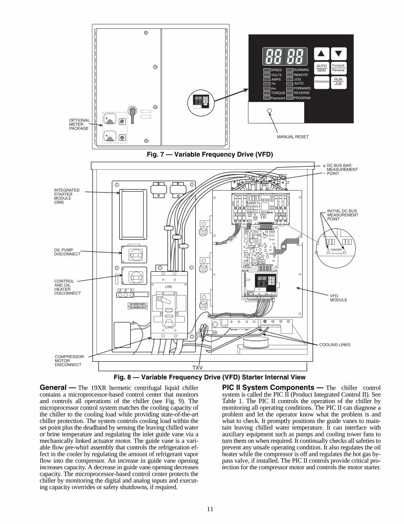
Unit-Mounted VFD (Optional) — The 19XRV unitwill be equipped with a variable frequency drive motor control-ler mounted on the unit. See Fig. 7 and 8. This VFD is usedwith low voltage motors between 380 and 480 VAC. It reducesthe starting current inrush by controlling the voltage and fre-quency to the compressor motor. Once the motor has accelerat-ed to minimum speed the PIC II modulates the compressorspeed and guide vane position to control chilled water tempera-ture. The VFD is further explained in the Controls section andTroubleshooting Guide section, pages 10 and 76.
There is a separate display located on the unit-mountedVFD. Operational parameters and fault codes are displayed rel-ative to the drive. Refer to specific drive literature along withtroubleshooting sections. The display is also the interface forentering specific chiller operational parameters. These parame-ters have been preprogrammed at the factory. An adhesivebacked label on the inside of the drive has been provided forverification of the specific job parameters. See Initial Start-UpChecklist section for details.
CONTROLS
DefinitionsANALOG SIGNAL — An analog signal varies in proportionto the monitored source. It quantifies values between operatinglimits. (Example: A temperature sensor is an analog device be-cause its resistance changes in proportion to the temperature,generating many values.)DISCRETE SIGNAL — A discrete signal is a 2-position rep-resentation of the value of a monitored source. (Example: Aswitch produces a discrete signal indicating whether a value isabove or below a set point or boundary by generating an on/off,high/low, or open/closed signal.)
5
1
2
3
6
4
7
LEGEND
Fig. 5 — Solid-State Starter Box,Internal View
1 — RediStart MICRO™ Input/Output Card2 — Fuses 1-4 (Hidden, not depicted)3 — Circuit Breaker 2 (CB2): Machine Control and Heater Power4 — Circuit Breaker 3 (CB3): Oil Pump Power5 — RediStart MICRO Central Processing Unit Card (CPU)6 — RediStart MICRO Power Card (hidden, not depicted)7 — RediStart MICRO Bypass Card (hidden, not depicted)
Fig. 6 — Typical Starter External View(Solid-State Starter Shown)
11
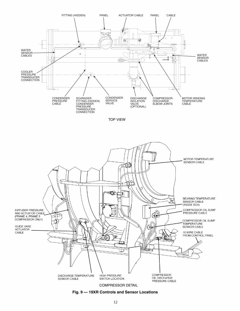
General — The 19XR hermetic centrifugal liquid chillercontains a microprocessor-based control center that monitorsand controls all operations of the chiller (see Fig. 9). Themicroprocessor control system matches the cooling capacity ofthe chiller to the cooling load while providing state-of-the-artchiller protection. The system controls cooling load within theset point plus the deadband by sensing the leaving chilled wateror brine temperature and regulating the inlet guide vane via amechanically linked actuator motor. The guide vane is a vari-able flow pre-whirl assembly that controls the refrigeration ef-fect in the cooler by regulating the amount of refrigerant vaporflow into the compressor. An increase in guide vane openingincreases capacity. A decrease in guide vane opening decreasescapacity. The microprocessor-based control center protects thechiller by monitoring the digital and analog inputs and execut-ing capacity overrides or safety shutdowns, if required.
PIC II System Components — The chiller controlsystem is called the PIC II (Product Integrated Control II). SeeTable 1. The PIC II controls the operation of the chiller bymonitoring all operating conditions. The PIC II can diagnose aproblem and let the operator know what the problem is andwhat to check. It promptly positions the guide vanes to main-tain leaving chilled water temperature. It can interface withauxiliary equipment such as pumps and cooling tower fans toturn them on when required. It continually checks all safeties toprevent any unsafe operating condition. It also regulates the oilheater while the compressor is off and regulates the hot gas by-pass valve, if installed. The PIC II controls provide critical pro-tection for the compressor motor and controls the motor starter.
SPEED
VOLTSAMPSHz
KwTORQUE
Password
RUNNING
REMOTEJOGAUTO
FORWARDREVERSE
PROGRAM
PRO-GRAM
ForwardReverse
ENTER
RUNJOB
AUTOMAN
SPEED
VOLTSAMPSHz
KwTORQUE
Password
RUNNING
REMOTEJOGAUTO
FORWARDREVERSE
PROGRAM
PROGRAM
ForwardReverse
ENTER
RUNJOB
AUTOMAN
MANUAL RESET
OPTIONALMETERPACKAGE
SPEED
VOLTSAMPSHz
KwTORQUE
Password
RUNNING
REMOTEJOGAUTO
FORWARDREVERSE
PROGRAM
PROGRAM
ForwardReverse
ENTER
RUNJOB
AUTOMAN
DANGERHIGH VOLTAGE
+ -
INITIAL DC BUSMEASUREMENTPOINT
DC BUS BARMEASUREMENTPOINT
+-
VFDMODULE
COOLING LINES
COMPRESSORMOTORDISCONNECT
TXV
CONTROLAND OILHEATERDISCONNECT
OIL PUMPDISCONNECT
INTEGRATEDSTARTERMODULE(ISM)
LINE
LOAD
Fig. 7 — Variable Frequency Drive (VFD)
Fig. 8 — Variable Frequency Drive (VFD) Starter Internal View
12
FITTING (HIDDEN) PANEL ACTUATOR CABLE PANEL CABLE
WATERSENSORCABLES
WATERSENSORCABLES
COOLERPRESSURETRANSDUCERCONNECTION
CONDENSERPRESSURECABLE
SCHRADERFITTING (HIDDEN)CONDENSERPRESSURETRANSDUCERCONNECTION
CONDENSERSERVICEVALVE
COMPRESSORDISCHARGEELBOW JOINTS
MOTOR WINDINGTEMPERATURECABLE
DISCHARGEISOLATIONVALVE(OPTIONAL)
TOP VIEW
COMPRESSOR DETAIL
Fig. 9 — 19XR Controls and Sensor Locations
13
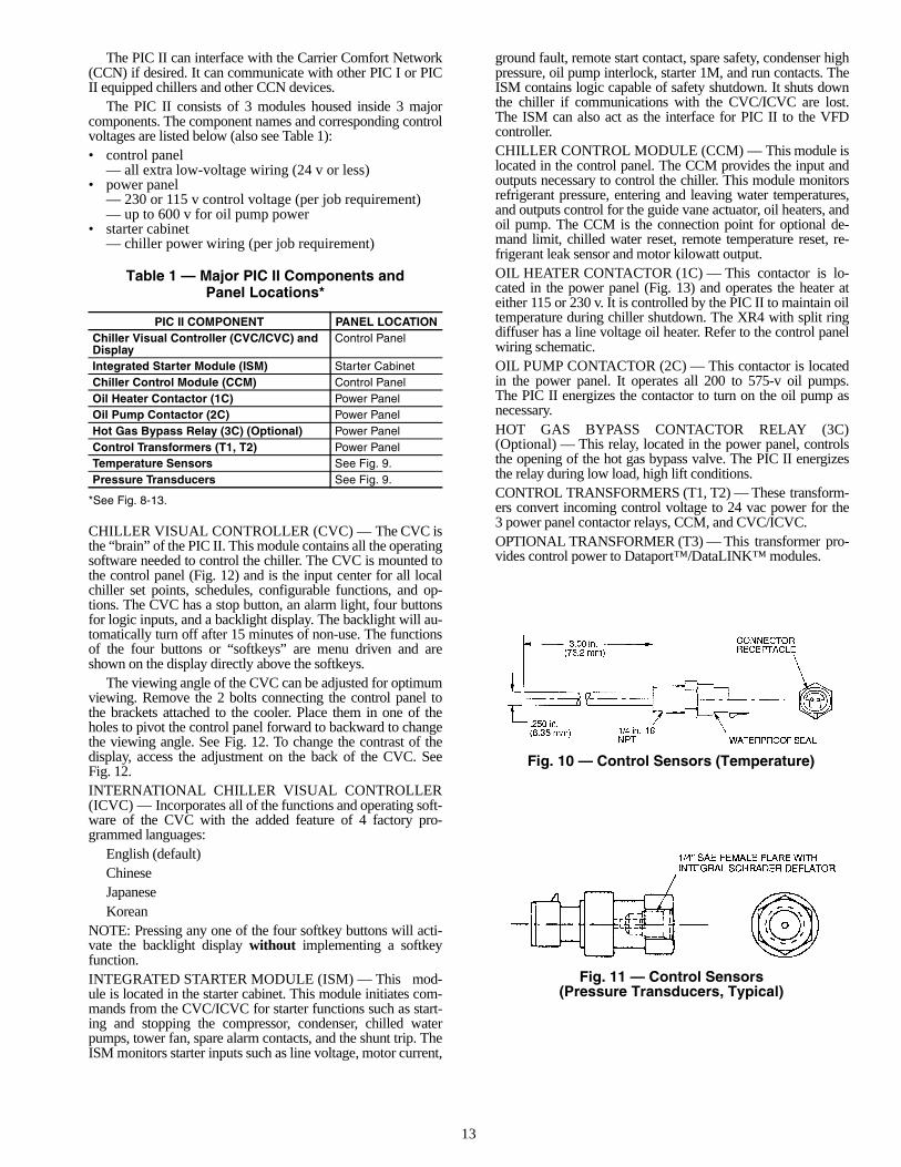
The PIC II can interface with the Carrier Comfort Network(CCN) if desired. It can communicate with other PIC I or PICII equipped chillers and other CCN devices.
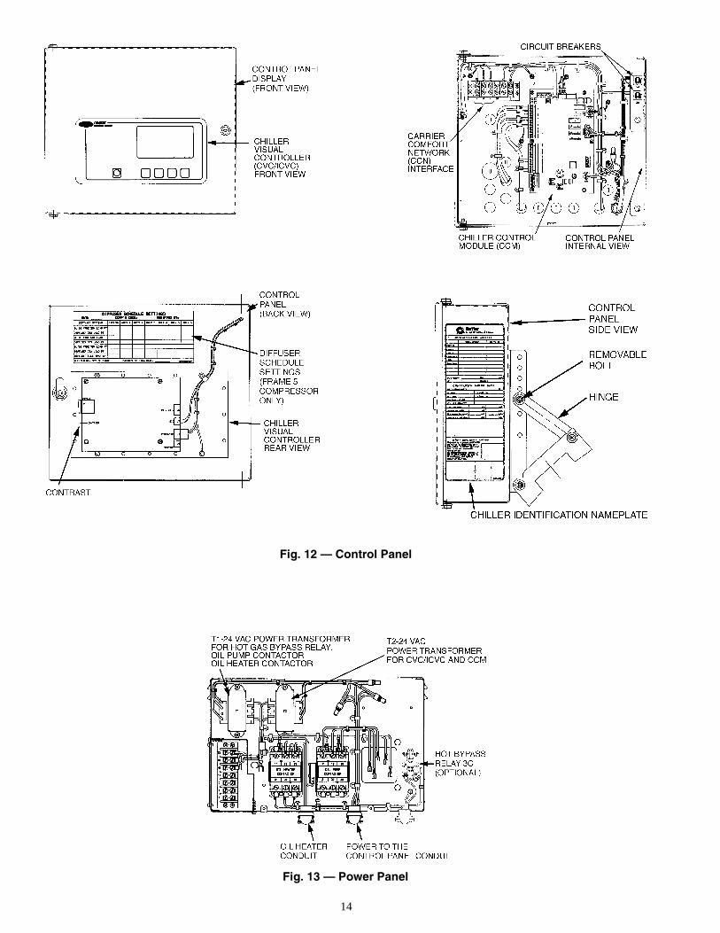
The PIC II consists of 3 modules housed inside 3 majorcomponents. The component names and corresponding controlvoltages are listed below (also see Table 1):• control panel
— all extra low-voltage wiring (24 v or less)• power panel
— 230 or 115 v control voltage (per job requirement)— up to 600 v for oil pump power
• starter cabinet— chiller power wiring (per job requirement)
Table 1 — Major PIC II Components andPanel Locations*
*See Fig. 8-13.
CHILLER VISUAL CONTROLLER (CVC) — The CVC isthe “brain” of the PIC II. This module contains all the operatingsoftware needed to control the chiller. The CVC is mounted tothe control panel (Fig. 12) and is the input center for all localchiller set points, schedules, configurable functions, and op-tions. The CVC has a stop button, an alarm light, four buttonsfor logic inputs, and a backlight display. The backlight will au-tomatically turn off after 15 minutes of non-use. The functionsof the four buttons or “softkeys” are menu driven and areshown on the display directly above the softkeys.
The viewing angle of the CVC can be adjusted for optimumviewing. Remove the 2 bolts connecting the control panel tothe brackets attached to the cooler. Place them in one of theholes to pivot the control panel forward to backward to changethe viewing angle. See Fig. 12. To change the contrast of thedisplay, access the adjustment on the back of the CVC. SeeFig. 12.INTERNATIONAL CHILLER VISUAL CONTROLLER(ICVC) — Incorporates all of the functions and operating soft-ware of the CVC with the added feature of 4 factory pro-grammed languages:
English (default)ChineseJapaneseKorean
NOTE: Pressing any one of the four softkey buttons will acti-vate the backlight display without implementing a softkeyfunction.INTEGRATED STARTER MODULE (ISM) — This mod-ule is located in the starter cabinet. This module initiates com-mands from the CVC/ICVC for starter functions such as start-ing and stopping the compressor, condenser, chilled waterpumps, tower fan, spare alarm contacts, and the shunt trip. TheISM monitors starter inputs such as line voltage, motor current,
ground fault, remote start contact, spare safety, condenser highpressure, oil pump interlock, starter 1M, and run contacts. TheISM contains logic capable of safety shutdown. It shuts downthe chiller if communications with the CVC/ICVC are lost.The ISM can also act as the interface for PIC II to the VFDcontroller.CHILLER CONTROL MODULE (CCM) — This module islocated in the control panel. The CCM provides the input andoutputs necessary to control the chiller. This module monitorsrefrigerant pressure, entering and leaving water temperatures,and outputs control for the guide vane actuator, oil heaters, andoil pump. The CCM is the connection point for optional de-mand limit, chilled water reset, remote temperature reset, re-frigerant leak sensor and motor kilowatt output.OIL HEATER CONTACTOR (1C) — This contactor is lo-cated in the power panel (Fig. 13) and operates the heater ateither 115 or 230 v. It is controlled by the PIC II to maintain oiltemperature during chiller shutdown. The XR4 with split ringdiffuser has a line voltage oil heater. Refer to the control panelwiring schematic.OIL PUMP CONTACTOR (2C) — This contactor is locatedin the power panel. It operates all 200 to 575-v oil pumps.The PIC II energizes the contactor to turn on the oil pump asnecessary.HOT GAS BYPASS CONTACTOR RELAY (3C)(Optional) — This relay, located in the power panel, controlsthe opening of the hot gas bypass valve. The PIC II energizesthe relay during low load, high lift conditions.CONTROL TRANSFORMERS (T1, T2) — These transform-ers convert incoming control voltage to 24 vac power for the3 power panel contactor relays, CCM, and CVC/ICVC.OPTIONAL TRANSFORMER (T3) — This transformer pro-vides control power to Dataport™/DataLINK™ modules.
PIC II COMPONENT PANEL LOCATIONChiller Visual Controller (CVC/ICVC) and Display
Control Panel
Integrated Starter Module (ISM) Starter CabinetChiller Control Module (CCM) Control PanelOil Heater Contactor (1C) Power PanelOil Pump Contactor (2C) Power PanelHot Gas Bypass Relay (3C) (Optional) Power PanelControl Transformers (T1, T2) Power PanelTemperature Sensors See Fig. 9.Pressure Transducers See Fig. 9.
Fig. 10 — Control Sensors (Temperature)
Fig. 11 — Control Sensors(Pressure Transducers, Typical)
14
Fig. 12 — Control Panel
Fig. 13 — Power Panel
15
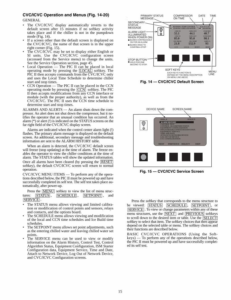
CVC/ICVC Operation and Menus (Fig. 14-20)GENERAL• The CVC/ICVC display automatically reverts to the
default screen after 15 minutes if no softkey activitytakes place and if the chiller is not in the pumpdownmode (Fig. 14).
• If a screen other than the default screen is displayed onthe CVC/ICVC, the name of that screen is in the upperright corner (Fig. 15).
• The CVC/ICVC may be set to display either English orSI units. Use the CVC/ICVC configuration screen(accessed from the Service menu) to change the units.See the Service Operation section, page 45.
• Local Operation — The PIC II can be placed in localoperating mode by pressing the softkey. ThePIC II then accepts commands from the CVC/ICVC onlyand uses the Local Time Schedule to determine chillerstart and stop times.
• CCN Operation — The PIC II can be placed in the CCNoperating mode by pressing the softkey. The PICII then accepts modifications from any CCN interface ormodule (with the proper authority), as well as from theCVC/ICVC. The PIC II uses the CCN time schedule todetermine start and stop times.
ALARMS AND ALERTS — An alarm shuts down the com-pressor. An alert does not shut down the compressor, but it no-tifies the operator that an unusual condition has occurred. Analarm (*) or alert (!) is indicated on the STATUS screens on thefar right field of the CVC/ICVC display screen.
Alarms are indicated when the control center alarm light (!)flashes. The primary alarm message is displayed on the defaultscreen. An additional, secondary message and troubleshootinginformation are sent to the ALARM HISTORY table.
When an alarm is detected, the CVC/ICVC default screenwill freeze (stop updating) at the time of alarm. The freeze en-ables the operator to view the chiller conditions at the time ofalarm. The STATUS tables will show the updated information.Once all alarms have been cleared (by pressing the softkey), the default CVC/ICVC screen will return to normaloperation.CVC/ICVC MENU ITEMS — To perform any of the opera-tions described below, the PIC II must be powered up and havesuccessfully completed its self test. The self test takes place au-tomatically, after power-up.
Press the softkey to view the list of menu struc-tures: , , , and
.• The STATUS menu allows viewing and limited calibra-
tion or modification of control points and sensors, relaysand contacts, and the options board.
• The SCHEDULE menu allows viewing and modificationof the local and CCN time schedules and Ice Build timeschedules.
• The SETPOINT menu allows set point adjustments, suchas the entering chilled water and leaving chilled water setpoints.
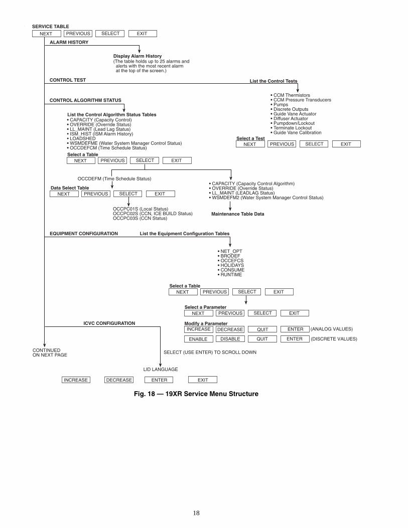
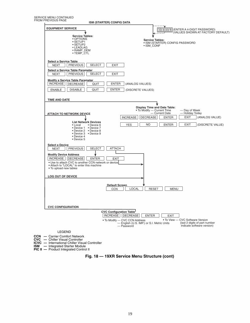
• The SERVICE menu can be used to view or modifyinformation on the Alarm History, Control Test, ControlAlgorithm Status, Equipment Configuration, ISM StarterConfiguration data, Equipment Service, Time and Date,Attach to Network Device, Log Out of Network Device,and CVC/ICVC Configuration screens.
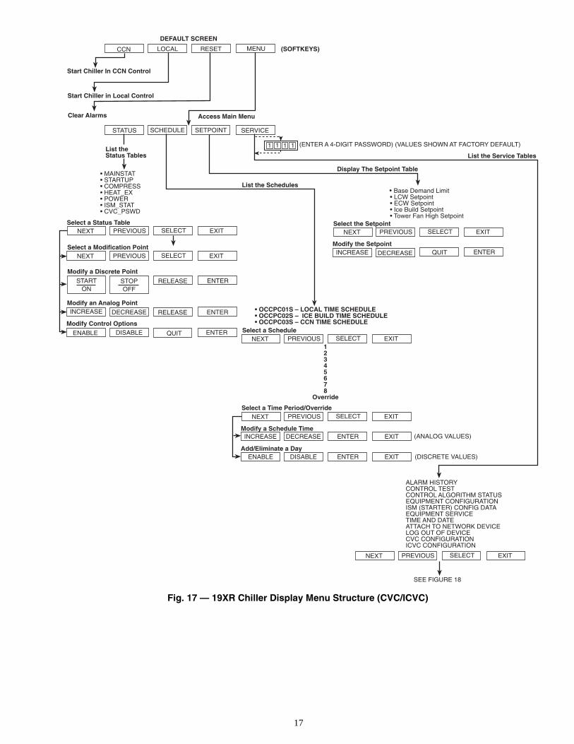
For more information on the menu structures, refer toFig. 17.
Press the softkey that corresponds to the menu structure tobe viewed: , , or
. To view or change parameters within any of thesemenu structures, use the and softkeysto scroll down to the desired item or table. Use the softkey to select that item. The softkey choices that then appeardepend on the selected table or menu. The softkey choices andtheir functions are described below.BASIC CVC/ICVC OPERATIONS (Using the Soft-keys) — To perform any of the operations described below,the PIC II must be powered up and have successfully complet-ed its self test.
LOCAL
CCN
RESET
MENUSTATUS SCHEDULE SETPOINT
SERVICE
STATUS SCHEDULE SETPOINTSERVICE
NEXT PREVIOUSSELECT
RUNNING TEMP CONTROLLEAVING CHILLED WATER
01-01-95 11:4828.8 HOURS
CHW IN CHW OUT EVAP REF
CDW IN CDW OUT COND REF
OIL PRESS OIL TEMP AMPS %
CCN LOCAL RESET MENU
55.1 44.1 40.7
85.0 95.0 98.1
21.8 132.9 93
PRIMARY STATUSMESSAGE
COMPRESSORON TIME
DATE TIME
SOFT KEYSMENULINE
EACH KEY'S FUNCTION ISDEFINED BY THE MENU DESCRIPTIONON MENU LINE ABOVE
ALARM LIGHT(ILLUMINATEDWHEN POWER ON)
STOP BUTTON• HOLD FOR ONE
SECOND TO STOP
••
BLINKS CONTINUOUSLYON FOR AN ALARMBLINKS ONCE TOCONFIRM A STOP
SECONDARYSTATUSMESSAGE
CONTROL TESTCONTROL ALGORITHM STATUSEQUIPMENT CONFIGURATIONISM (STARTER) CONFIGURATION DATAEQUIPMENT SERVICETIME AND DATEATTACH TO NETWORK DEVICELOG OUT OF DEVICECVC CONFIGURATION
ALARM HISTORY
19XR_II SERVICE
Fig. 15 — CVC/ICVC Service Screen
Fig. 14 — CVC/ICVC Default Screen
16
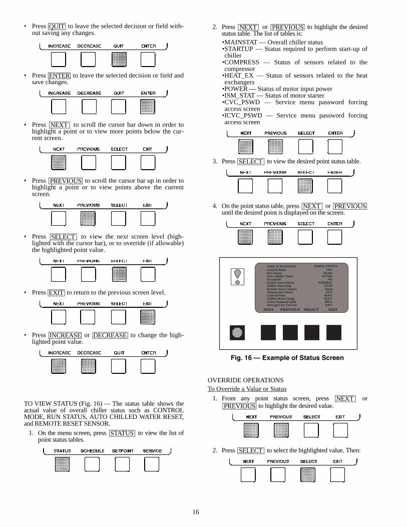
• Press to leave the selected decision or field with-out saving any changes.
• Press to leave the selected decision or field andsave changes.
• Press to scroll the cursor bar down in order tohighlight a point or to view more points below the cur-rent screen.
• Press to scroll the cursor bar up in order tohighlight a point or to view points above the currentscreen.
• Press to view the next screen level (high-lighted with the cursor bar), or to override (if allowable)the highlighted point value.
• Press to return to the previous screen level.
• Press or to change the high-lighted point value.
TO VIEW STATUS (Fig. 16) — The status table shows theactual value of overall chiller status such as CONTROLMODE, RUN STATUS, AUTO CHILLED WATER RESET,and REMOTE RESET SENSOR.
1. On the menu screen, press to view the list ofpoint status tables.
2. Press or to highlight the desiredstatus table. The list of tables is:•MAINSTAT — Overall chiller status•STARTUP — Status required to perform start-up ofchiller
•COMPRESS — Status of sensors related to thecompressor
•HEAT_EX — Status of sensors related to the heatexchangers
•POWER — Status of motor input power•ISM_STAT — Status of motor starter•CVC_PSWD — Service menu password forcingaccess screen
•ICVC_PSWD — Service menu password forcingaccess screen
3. Press to view the desired point status table.
4. On the point status table, press or until the desired point is displayed on the screen.
OVERRIDE OPERATIONSTo Override a Value or Status
1. From any point status screen, press or to highlight the desired value.
2. Press to select the highlighted value. Then:
QUIT
ENTER
NEXT
PREVIOUS
SELECT
EXIT
INCREASE DECREASE
STATUS
NEXT PREVIOUS
SELECT
NEXT PREVIOUS
NEXTPREVIOUS
SELECT
19XR_II MAINSTAT POINT STATUSControl ModeRun StatusStart Inhibit TimerOccupied?System Alert/AlarmChiller Start/StopRemote Start ContactTemperature ResetControl PointChilled Water TempActive Demand LimitAverage Line Current
OFFReady
0.0 MinNO
NORMALSTOPOpen0.0 F
44.0 F44.6 F100%0.0%
Fig. 16 — Example of Status Screen
17
•CCN LOCAL RESET MENU
DEFAULT SCREEN
Start Chiller In CCN Control
Start Chiller in Local Control
Clear Alarms
STATUS SCHEDULE SETPOINT SERVICE
(SOFTKEYS)
Access Main Menu
List theStatus Tables
Display The Setpoint Table
(ENTER A 4-DIGIT PASSWORD) (VALUES SHOWN AT FACTORY DEFAULT)
List the Service Tables
• OCCPC01S – LOCAL TIME SCHEDULE• OCCPC02S – ICE BUILD TIME SCHEDULE• OCCPC03S – CCN TIME SCHEDULE
List the Schedules
1
ALARM HISTORYCONTROL TESTCONTROL ALGORITHM STATUSEQUIPMENT CONFIGURATIONISM (STARTER) CONFIG DATAEQUIPMENT SERVICETIME AND DATEATTACH TO NETWORK DEVICELOG OUT OF DEVICECVC CONFIGURATIONICVC CONFIGURATION
Base Demand Limit • LCW Setpoint • ECW Setpoint • Ice Build Setpoint • Tower Fan High Setpoint
EXITSELECTPREVIOUSNEXTSelect a Schedule
12345678
Override
ENABLE DISABLE
EXITSELECTPREVIOUSNEXTSelect a Time Period/Override
Modify a Schedule Time
ENTER EXIT
INCREASE DECREASE ENTER EXIT (ANALOG VALUES)
(DISCRETE VALUES)Add/Eliminate a Day
1 1 1
Select a Status TableNEXT PREVIOUS SELECT EXIT
STARTON
STOPOFF
RELEASE ENTER
EXITNEXT PREVIOUS SELECT
ENTERENABLE DISABLE QUIT
DECREASEINCREASE ENTERRELEASE
Select a Modification Point
Modify a Discrete Point
Modify an Analog Point
Modify Control Options
• MAINSTAT• STARTUP• COMPRESS• HEAT_EX• POWER• ISM_STAT• CVC_PSWD
Modify the SetpointDECREASEINCREASE QUIT ENTER
NEXT PREVIOUS SELECT EXITSelect the Setpoint
•
NEXT PREVIOUS SELECT EXIT
SEE FIGURE 18
Fig. 17 — 19XR Chiller Display Menu Structure (CVC/ICVC)
18
•NEXT PREVIOUS SELECT EXIT
SERVICE TABLE
Display Alarm History(The table holds up to 25 alarms and alerts with the most recent alarm at the top of the screen.)
• CCM Thermistors• CCM Pressure Transducers• Pumps• Discrete Outputs• Guide Vane Actuator• Diffuser Actuator• Pumpdown/Lockout• Terminate Lockout• Guide Vane Calibration
CONTINUEDON NEXT PAGE
CONTROL ALGORITHM STATUS
CONTROL TEST
ALARM HISTORY
List the Control Tests
NEXT PREVIOUS SELECT EXITSelect a Test
List the Control Algorithm Status Tables• CAPACITY (Capacity Control)• OVERRIDE (Override Status)• LL_MAINT (Lead Lag Status)• ISM_HIST (ISM Alarm History)• LOADSHED• WSMDEFME (Water System Manager Control Status)• OCCDEFCM (Time Schedule Status)
NEXT PREVIOUS SELECT EXITSelect a Table
• NET_OPT• BRODEF• OCCEFCS• HOLIDAYS• CONSUME• RUNTIME
(ANALOG VALUES)
(DISCRETE VALUES)
Select a ParameterNEXT PREVIOUS SELECT EXIT
Modify a Parameter
ENTERENABLE DISABLE QUIT
DECREASEINCREASE ENTERQUIT
NEXT PREVIOUS SELECT EXITSelect a Table
EQUIPMENT CONFIGURATION List the Equipment Configuration Tables
• CAPACITY (Capacity Control Algorithm)• OVERRIDE (Override Status)• LL_MAINT (LEADLAG Status)• WSMDEFM2 (Water System Manager Control Status)
Maintenance Table Data
NEXT PREVIOUS SELECT EXITData Select Table
OCCPC01S (Local Status)OCCPC02S (CCN, ICE BUILD Status)OCCPC03S (CCN Status)
OCCDEFM (Time Schedule Status)
ICVC CONFIGURATION
SELECT (USE ENTER) TO SCROLL DOWN
LID LANGUAGE
INCREASE DECREASE ENTER EXIT
Fig. 18 — 19XR Service Menu Structure
19
NEXT PREVIOUS SELECT EXIT
SERVICE MENU CONTINUEDFROM PREVIOUS PAGE
Select a Service Table
Select a Service Table ParameterNEXT PREVIOUS SELECT EXIT
Modify a Service Table Parameter(ANALOG VALUES)
(DISCRETE VALUES)
TIME AND DATE
Display Time and Date Table:• To Modify — Current Time — Day of Week
— Current Date — Holiday TodayATTACH TO NETWORK DEVICEENTERDECREASEINCREASE EXIT
ENTERENABLE DISABLE QUIT
DECREASEINCREASE ENTERQUIT
Select a DeviceATTACHNEXT PREVIOUS SELECT
Modify Device AddressEXITINCREASE DECREASE ENTER
• Use to attach CVC to another CCN network or device• Attach to "LOCAL" to enter this machine• To upload new tables
Default ScreenMENURESETCCN LOCAL
LOG OUT OF DEVICE
List Network Devices• Local• Device 1• Device 2• Device 3• Device 4• Device 5
• Device 6• Device 7• Device 8• Device 9
Service Tables:• OPTIONS• SETUP1• SETUP2• LEADLAG• RAMP_DEM• TEMP_CTL
EQUIPMENT SERVICE
ISM (STARTER) CONFIG DATA
Service Tables:• ISM (STARTER) CONFIG PASSWORD• ISM_CONF
(ENTER A 4-DIGIT PASSWORD)(VALUES SHOWN AT FACTORY DEFAULT)
4 4 4 4
CVC CONFIGURATION
EXITINCREASE DECREASE ENTERCVC Configuration Table
• To Modify — CVC CCN Address— English (U.S. IMP.) or S.I. Metric Units— Password
• To View — CVC Software Version (last 2 digits of part number
indicate software version)
ENTERNOYES EXIT
(ANALOG VALUE)
(DISCRETE VALUE)
LEGENDCCN — Carrier Comfort NetworkCVC — Chiller Visual ControllerICVC — International Chiller Visual ControllerISM — Integrated Starter ModulePIC II — Product Integrated Control II
Fig. 18 — 19XR Service Menu Structure (cont)
20
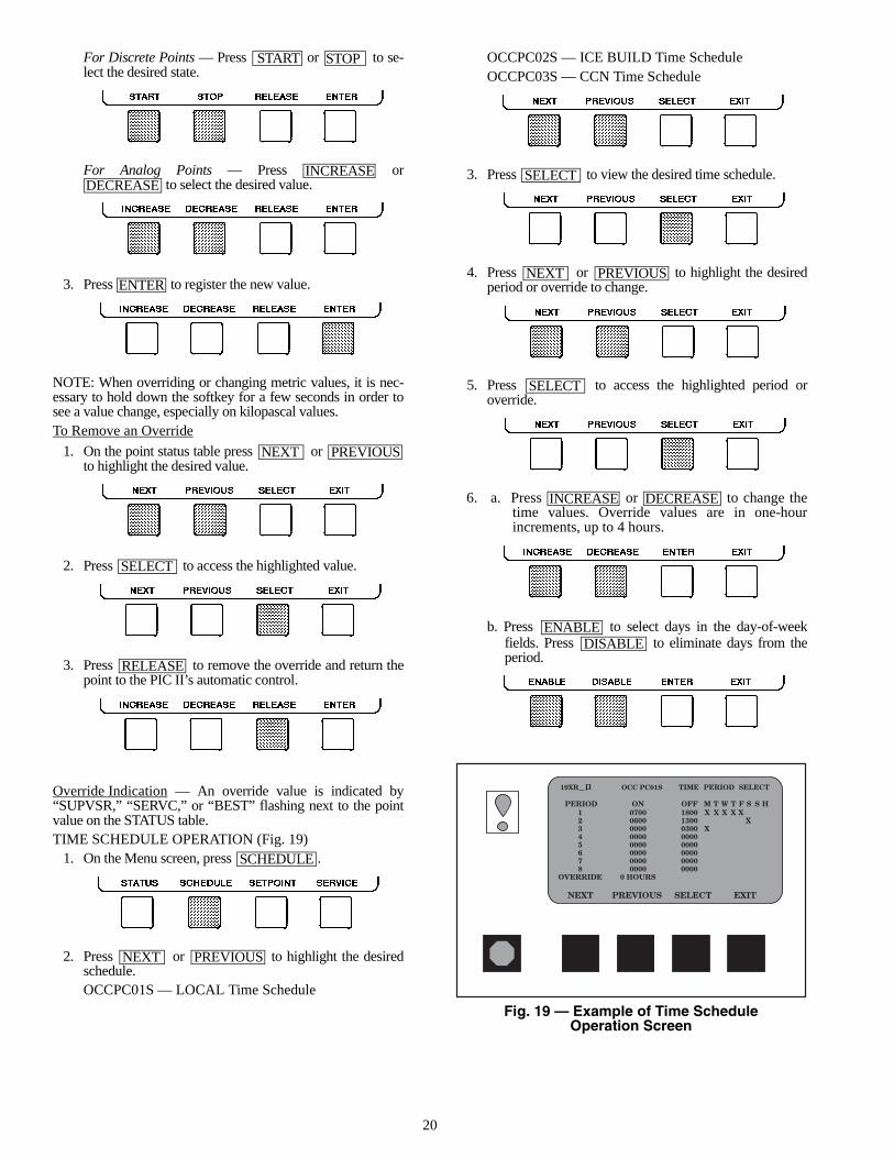
For Discrete Points — Press or to se-lect the desired state.
For Analog Points — Press or to select the desired value.
3. Press to register the new value.
NOTE: When overriding or changing metric values, it is nec-essary to hold down the softkey for a few seconds in order tosee a value change, especially on kilopascal values.To Remove an Override
1. On the point status table press or to highlight the desired value.
2. Press to access the highlighted value.
3. Press to remove the override and return thepoint to the PIC II’s automatic control.
Override Indication — An override value is indicated by“SUPVSR,” “SERVC,” or “BEST” flashing next to the pointvalue on the STATUS table.TIME SCHEDULE OPERATION (Fig. 19)
1. On the Menu screen, press .
2. Press or to highlight the desiredschedule.OCCPC01S — LOCAL Time Schedule
OCCPC02S — ICE BUILD Time ScheduleOCCPC03S — CCN Time Schedule
3. Press to view the desired time schedule.
4. Press or to highlight the desiredperiod or override to change.
5. Press to access the highlighted period oroverride.
6. a. Press or to change thetime values. Override values are in one-hourincrements, up to 4 hours.
b. Press to select days in the day-of-weekfields. Press to eliminate days from theperiod.
START STOP
INCREASEDECREASE
ENTER
NEXT PREVIOUS
SELECT
RELEASE
SCHEDULE
NEXT PREVIOUS
SELECT
NEXT PREVIOUS
SELECT
INCREASE DECREASE
ENABLEDISABLE
Fig. 19 — Example of Time ScheduleOperation Screen
21
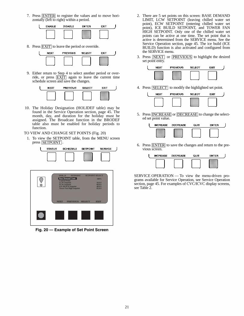
7. Press to register the values and to move hori-zontally (left to right) within a period.
8. Press to leave the period or override.
9. Either return to Step 4 to select another period or over-ride, or press again to leave the current timeschedule screen and save the changes.
10. The Holiday Designation (HOLIDEF table) may befound in the Service Operation section, page 45. Themonth, day, and duration for the holiday must beassigned. The Broadcast function in the BRODEFtable also must be enabled for holiday periods tofunction.
TO VIEW AND CHANGE SET POINTS (Fig. 20)1. To view the SETPOINT table, from the MENU screen
press .
2. There are 5 set points on this screen: BASE DEMANDLIMIT, LCW SETPOINT (leaving chilled water setpoint), ECW SETPOINT (entering chilled water setpoint), ICE BUILD SETPOINT, and TOWER FANHIGH SETPOINT. Only one of the chilled water setpoints can be active at one time. The set point that isactive is determined from the SERVICE menu. See theService Operation section, page 45. The ice build (ICEBUILD) function is also activated and configured fromthe SERVICE menu.
3. Press or to highlight the desiredset point entry.
4. Press to modify the highlighted set point.
5. Press or to change the select-ed set point value.
6. Press to save the changes and return to the pre-vious screen.
SERVICE OPERATION — To view the menu-driven pro-grams available for Service Operation, see Service Operationsection, page 45. For examples of CVC/ICVC display screens,see Table 2.
ENTER
EXIT
EXIT
SETPOINT
NEXT PREVIOUS
SELECT
INCREASE DECREASE
ENTER
19XR_II SETPOINT SELECTSETPOINT
Base Demand LimitControl PointLCW SetpointECW SetpointICE BUILD SetpointTower Fan High Setpoint
100%
50.0 F60.0 F40.0 F85.0 F
Fig. 20 — Example of Set Point Screen
22
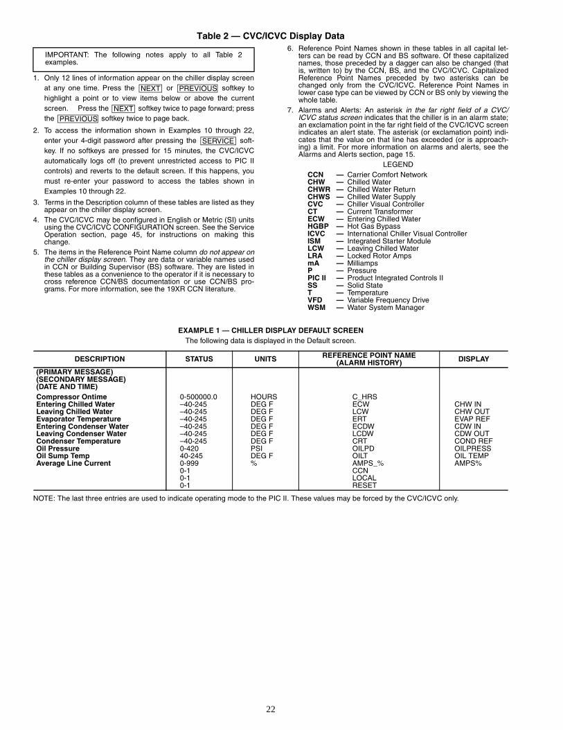
Table 2 — CVC/ICVC Display Data
1. Only 12 lines of information appear on the chiller display screenat any one time. Press the or softkey tohighlight a point or to view items below or above the currentscreen. Press the softkey twice to page forward; pressthe softkey twice to page back.
2. To access the information shown in Examples 10 through 22,enter your 4-digit password after pressing the soft-key. If no softkeys are pressed for 15 minutes, the CVC/ICVCautomatically logs off (to prevent unrestricted access to PIC IIcontrols) and reverts to the default screen. If this happens, youmust re-enter your password to access the tables shown inExamples 10 through 22.
3. Terms in the Description column of these tables are listed as theyappear on the chiller display screen.
4. The CVC/ICVC may be configured in English or Metric (SI) unitsusing the CVC/ICVC CONFIGURATION screen. See the ServiceOperation section, page 45, for instructions on making thischange.
5. The items in the Reference Point Name column do not appear onthe chiller display screen. They are data or variable names usedin CCN or Building Supervisor (BS) software. They are listed inthese tables as a convenience to the operator if it is necessary tocross reference CCN/BS documentation or use CCN/BS pro-grams. For more information, see the 19XR CCN literature.
6. Reference Point Names shown in these tables in all capital let-ters can be read by CCN and BS software. Of these capitalizednames, those preceded by a dagger can also be changed (thatis, written to) by the CCN, BS, and the CVC/ICVC. CapitalizedReference Point Names preceded by two asterisks can bechanged only from the CVC/ICVC. Reference Point Names inlower case type can be viewed by CCN or BS only by viewing thewhole table.
7. Alarms and Alerts: An asterisk in the far right field of a CVC/ICVC status screen indicates that the chiller is in an alarm state;an exclamation point in the far right field of the CVC/ICVC screenindicates an alert state. The asterisk (or exclamation point) indi-cates that the value on that line has exceeded (or is approach-ing) a limit. For more information on alarms and alerts, see theAlarms and Alerts section, page 15.
LEGEND
EXAMPLE 1 — CHILLER DISPLAY DEFAULT SCREENThe following data is displayed in the Default screen.
NOTE: The last three entries are used to indicate operating mode to the PIC II. These values may be forced by the CVC/ICVC only.
IMPORTANT: The following notes apply to all Table 2examples.
NEXT PREVIOUS
NEXTPREVIOUS
SERVICE
CCN — Carrier Comfort NetworkCHW — Chilled WaterCHWR — Chilled Water ReturnCHWS — Chilled Water SupplyCVC — Chiller Visual ControllerCT — Current TransformerECW — Entering Chilled WaterHGBP — Hot Gas BypassICVC — International Chiller Visual ControllerISM — Integrated Starter ModuleLCW — Leaving Chilled WaterLRA — Locked Rotor AmpsmA — MilliampsP — PressurePIC II — Product Integrated Controls IISS — Solid StateT — TemperatureVFD — Variable Frequency DriveWSM — Water System Manager
DESCRIPTION STATUS UNITS REFERENCE POINT NAME(ALARM HISTORY) DISPLAY
(PRIMARY MESSAGE)(SECONDARY MESSAGE)(DATE AND TIME)Compressor Ontime 0-500000.0 HOURS C_HRSEntering Chilled Water –40-245 DEG F ECW CHW INLeaving Chilled Water –40-245 DEG F LCW CHW OUTEvaporator Temperature –40-245 DEG F ERT EVAP REFEntering Condenser Water –40-245 DEG F ECDW CDW INLeaving Condenser Water –40-245 DEG F LCDW CDW OUTCondenser Temperature –40-245 DEG F CRT COND REFOil Pressure 0-420 PSI OILPD OILPRESSOil Sump Temp 40-245 DEG F OILT OIL TEMPAverage Line Current 0-999 % AMPS_% AMPS%
0-1 CCN0-1 LOCAL0-1 RESET
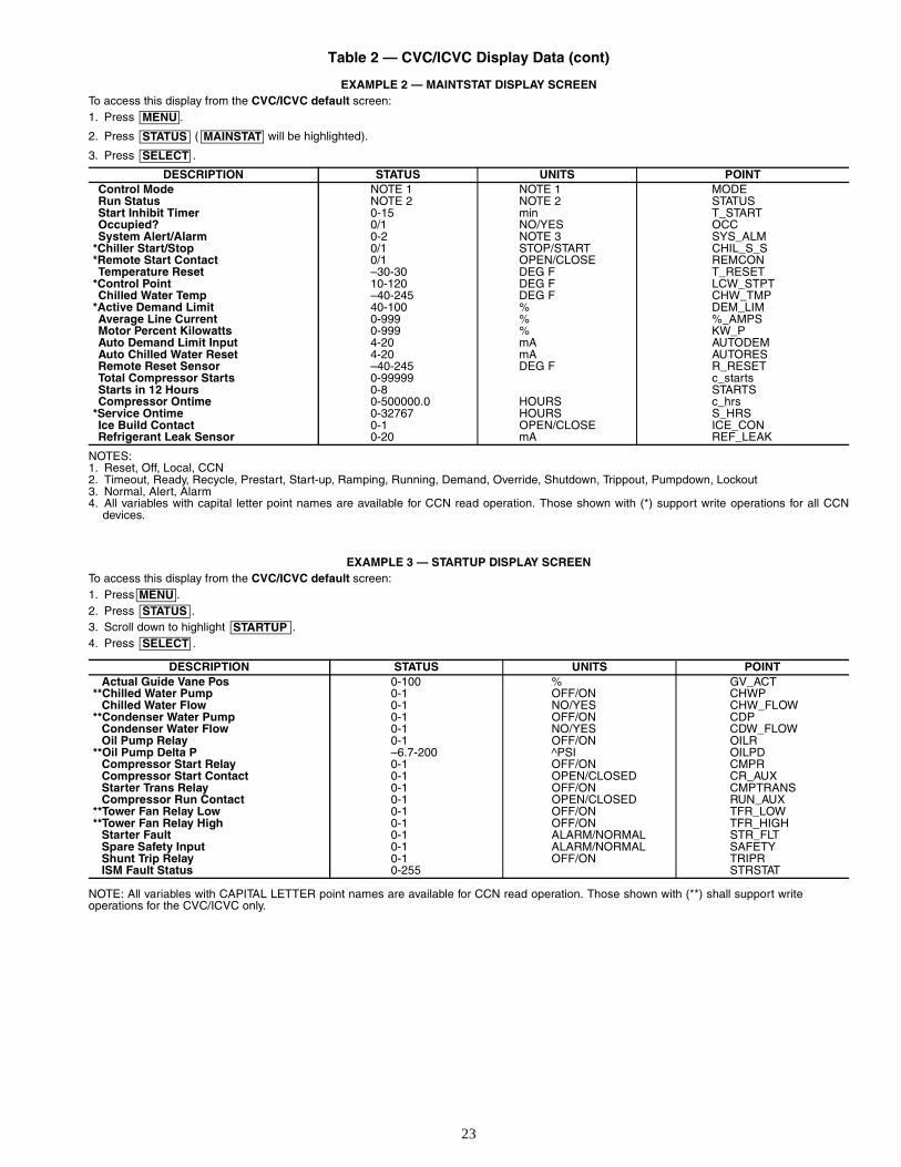
23
Table 2 — CVC/ICVC Display Data (cont)
EXAMPLE 2 — MAINTSTAT DISPLAY SCREENTo access this display from the CVC/ICVC default screen:1. Press .
2. Press ( will be highlighted).
3. Press .
NOTES:1. Reset, Off, Local, CCN2. Timeout, Ready, Recycle, Prestart, Start-up, Ramping, Running, Demand, Override, Shutdown, Trippout, Pumpdown, Lockout3. Normal, Alert, Alarm4. All variables with capital letter point names are available for CCN read operation. Those shown with (*) support write operations for all CCN
devices.
EXAMPLE 3 — STARTUP DISPLAY SCREENTo access this display from the CVC/ICVC default screen:1. Press .2. Press .3. Scroll down to highlight .4. Press .
NOTE: All variables with CAPITAL LETTER point names are available for CCN read operation. Those shown with (**) shall support writeoperations for the CVC/ICVC only.
DESCRIPTION STATUS UNITS POINTControl Mode NOTE 1 NOTE 1 MODERun Status NOTE 2 NOTE 2 STATUSStart Inhibit Timer 0-15 min T_STARTOccupied? 0/1 NO/YES OCCSystem Alert/Alarm 0-2 NOTE 3 SYS_ALM
*Chiller Start/Stop 0/1 STOP/START CHIL_S_S*Remote Start Contact 0/1 OPEN/CLOSE REMCONTemperature Reset –30-30 DEG F T_RESET
*Control Point 10-120 DEG F LCW_STPTChilled Water Temp –40-245 DEG F CHW_TMP
*Active Demand Limit 40-100 % DEM_LIMAverage Line Current 0-999 % %_AMPSMotor Percent Kilowatts 0-999 % KW_PAuto Demand Limit Input 4-20 mA AUTODEMAuto Chilled Water Reset 4-20 mA AUTORESRemote Reset Sensor –40-245 DEG F R_RESETTotal Compressor Starts 0-99999 c_startsStarts in 12 Hours 0-8 STARTSCompressor Ontime 0-500000.0 HOURS c_hrs
*Service Ontime 0-32767 HOURS S_HRSIce Build Contact 0-1 OPEN/CLOSE ICE_CONRefrigerant Leak Sensor 0-20 mA REF_LEAK
DESCRIPTION STATUS UNITS POINTActual Guide Vane Pos 0-100 % GV_ACT
**Chilled Water Pump 0-1 OFF/ON CHWPChilled Water Flow 0-1 NO/YES CHW_FLOW
**Condenser Water Pump 0-1 OFF/ON CDPCondenser Water Flow 0-1 NO/YES CDW_FLOWOil Pump Relay 0-1 OFF/ON OILR
**Oil Pump Delta P –6.7-200 ^PSI OILPDCompressor Start Relay 0-1 OFF/ON CMPRCompressor Start Contact 0-1 OPEN/CLOSED CR_AUXStarter Trans Relay 0-1 OFF/ON CMPTRANSCompressor Run Contact 0-1 OPEN/CLOSED RUN_AUX
**Tower Fan Relay Low 0-1 OFF/ON TFR_LOW**Tower Fan Relay High 0-1 OFF/ON TFR_HIGH
Starter Fault 0-1 ALARM/NORMAL STR_FLTSpare Safety Input 0-1 ALARM/NORMAL SAFETYShunt Trip Relay 0-1 OFF/ON TRIPRISM Fault Status 0-255 STRSTAT
MENU
STATUS MAINSTAT
SELECT
MENUSTATUS
STARTUPSELECT
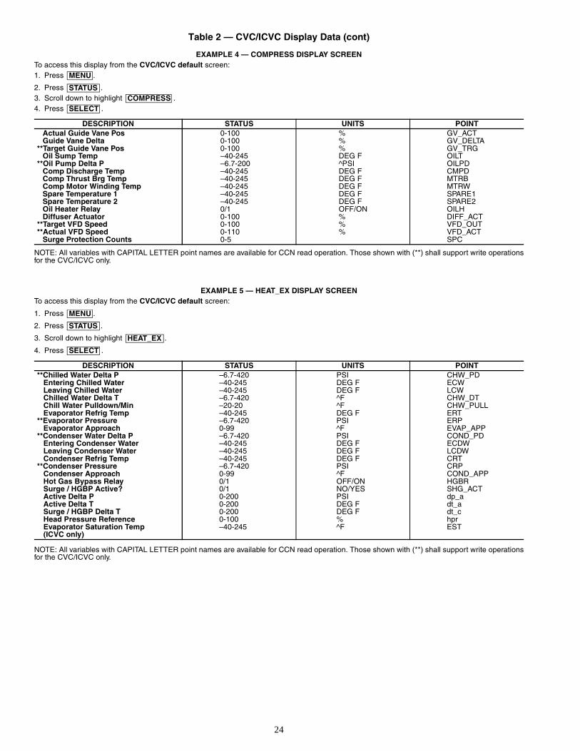
24
Table 2 — CVC/ICVC Display Data (cont)
EXAMPLE 4 — COMPRESS DISPLAY SCREENTo access this display from the CVC/ICVC default screen:1. Press .
2. Press .3. Scroll down to highlight .4. Press .
NOTE: All variables with CAPITAL LETTER point names are available for CCN read operation. Those shown with (**) shall support write operationsfor the CVC/ICVC only.
EXAMPLE 5 — HEAT_EX DISPLAY SCREENTo access this display from the CVC/ICVC default screen:
1. Press .
2. Press .
3. Scroll down to highlight .
4. Press .
NOTE: All variables with CAPITAL LETTER point names are available for CCN read operation. Those shown with (**) shall support write operationsfor the CVC/ICVC only.
DESCRIPTION STATUS UNITS POINT Actual Guide Vane Pos 0-100 % GV_ACTGuide Vane Delta 0-100 % GV_DELTA
**Target Guide Vane Pos 0-100 % GV_TRGOil Sump Temp –40-245 DEG F OILT
**Oil Pump Delta P –6.7-200 ^PSI OILPDComp Discharge Temp –40-245 DEG F CMPDComp Thrust Brg Temp –40-245 DEG F MTRBComp Motor Winding Temp –40-245 DEG F MTRWSpare Temperature 1 –40-245 DEG F SPARE1Spare Temperature 2 –40-245 DEG F SPARE2Oil Heater Relay 0/1 OFF/ON OILHDiffuser Actuator 0-100 % DIFF_ACT
**Target VFD Speed 0-100 % VFD_OUT**Actual VFD Speed 0-110 % VFD_ACT
Surge Protection Counts 0-5 SPC
DESCRIPTION STATUS UNITS POINT **Chilled Water Delta P –6.7-420 PSI CHW_PD
Entering Chilled Water –40-245 DEG F ECWLeaving Chilled Water –40-245 DEG F LCWChilled Water Delta T –6.7-420 ^F CHW_DTChill Water Pulldown/Min –20-20 ^F CHW_PULLEvaporator Refrig Temp –40-245 DEG F ERT
**Evaporator Pressure –6.7-420 PSI ERPEvaporator Approach 0-99 ^F EVAP_APP
**Condenser Water Delta P –6.7-420 PSI COND_PDEntering Condenser Water –40-245 DEG F ECDWLeaving Condenser Water –40-245 DEG F LCDWCondenser Refrig Temp –40-245 DEG F CRT
**Condenser Pressure –6.7-420 PSI CRPCondenser Approach 0-99 ^F COND_APPHot Gas Bypass Relay 0/1 OFF/ON HGBRSurge / HGBP Active? 0/1 NO/YES SHG_ACTActive Delta P 0-200 PSI dp_aActive Delta T 0-200 DEG F dt_aSurge / HGBP Delta T 0-200 DEG F dt_cHead Pressure Reference 0-100 % hprEvaporator Saturation Temp (ICVC only)
–40-245 ^F EST
MENU
STATUSCOMPRESS
SELECT
MENU
STATUS
HEAT_EX
SELECT
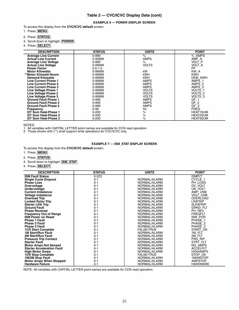
25
Table 2 — CVC/ICVC Display Data (cont)
EXAMPLE 6 — POWER DISPLAY SCREENTo access this display from the CVC/ICVC default screen:1. Press .
2. Press .3. Scroll down to highlight .4. Press .
NOTES:1. All variables with CAPITAL LETTER point names are available for CCN read operation.2. Those shown with (**) shall support write operations for CVC/ICVC only.
EXAMPLE 7 — ISM_STAT DISPLAY SCREENTo access this display from the CVC/ICVC default screen:1. Press .
2. Press .3. Scroll down to highlight .4. Press .
NOTE: All variables with CAPITAL LETTER point names are available for CCN read operation.
DESCRIPTION STATUS UNITS POINTAverage Line Current 0-999 % %_AMPSActual Line Current 0-99999 AMPS AMP_AAverage Line Voltage 0-999 % VOLT_PActual Line Voltage 0-99999 VOLTS VOLT_APower Factor 0.0-1.0 PFMotor Kilowatts 0-99999 kW KW_A
**Motor Kilowatt-Hours 0-99999 kWH KWH Demand Kilowatts 0-99999 kWH DEM_KWHLine Current Phase 1 0-99999 AMPS AMPS_1Line Current Phase 2 0-99999 AMPS AMPS_2Line Current Phase 3 0-99999 AMPS AMPS_3 Line Voltage Phase 1 0-99999 VOLTS VOLTS_1Line Voltage Phase 2 0-99999 VOLTS VOLTS_2Line Voltage Phase 3 0-99999 VOLTS VOLTS_3Ground Fault Phase 1 0-999 AMPS GF_1Ground Fault Phase 2 0-999 AMPS GF_2Ground Fault Phase 3 0-999 AMPS GF_3Frequency 0-99 Hz FREQI2T Sum Heat-Phase 1 0-200 % HEAT1SUMI2T Sum Heat-Phase 2 0-200 % HEAT2SUMI2T Sum Heat-Phase 3 0-200 % HEAT3SUM
DESCRIPTION STATUS UNITS POINTISM Fault Status 0-223 ISMFLTSingle Cycle Dropout 0-1 NORMAL/ALARM CYCLE_1Phase Loss 0-1 NORMAL/ALARM PH_LOSSOvervoltage 0-1 NORMAL/ALARM OV_VOLTUndervoltage 0-1 NORMAL/ALARM UN_VOLTCurrent Imbalance 0-1 NORMAL/ALARM AMP_UNBVoltage Imbalance 0-1 NORMAL/ALARM VOLT_UNBOverload Trip 0-1 NORMAL/ALARM OVERLOADLocked Rotor Trip 0-1 NORMAL/ALARM LRATRIPStarter LRA Trip 0-1 NORMAL/ALARM SLRATRIPGround Fault 0-1 NORMAL/ALARM GRND_FLTPhase Reversal 0-1 NORMAL/ALARM PH_REVFrequency Out of Range 0-1 NORMAL/ALARM FREQFLTISM Power on Reset 0-1 NORMAL/ALARM ISM_PORPhase 1 Fault 0-1 NORMAL/ALARM PHASE_1Phase 2 Fault 0-1 NORMAL/ALARM PHASE_2Phase 3 Fault 0-1 NORMAL/ALARM PHASE_31CR Start Complete 0-1 FALSE/TRUE START_OK1M Start/Run Fault 0-1 NORMAL/ALARM 1M_FLT2M Start/Run Fault 0-1 NORMAL/ALARM 2M_FLTPressure Trip Contact 0-1 NORMAL/ALARM PRS_RIPStarter Fault 0-1 NORMAL/ALARM STRT_FLTMotor Amps Not Sensed 0-1 NORMAL/ALARM NO_AMPSStarter Acceleration Fault 0-1 NORMAL/ALARM ACCELFLTHigh Motor Amps 0-1 NORMAL/ALARM HIGHAMPS1CR Stop Complete 0-1 FALSE/TRUE STOP_OK1M/2M Stop Fault 0-1 NORMAL/ALARM 1M2MSTOPMotor Amps When Stopped 0-1 NORMAL/ALARM AMPSTOPHardware Failure 0-1 NORMAL/ALARM HARDWARE
MENU
STATUSPOWER
SELECT
MENU
STATUSISM_STAT
SELECT
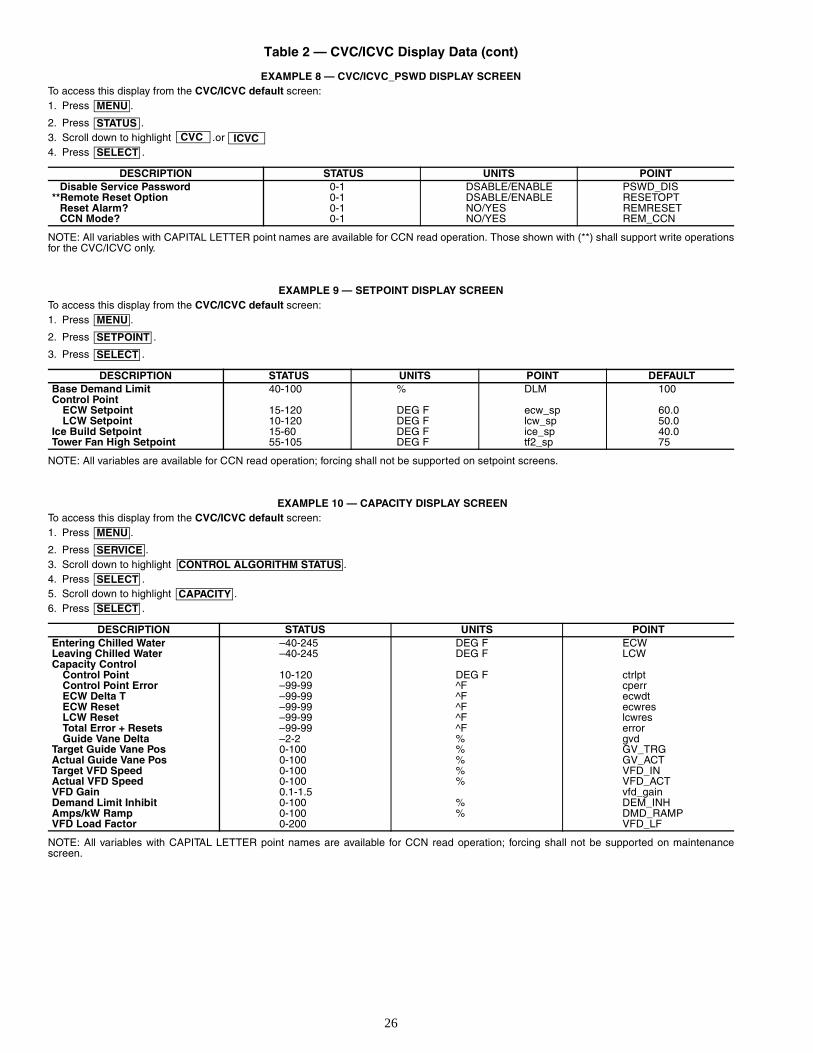
26
Table 2 — CVC/ICVC Display Data (cont)
EXAMPLE 8 — CVC/ICVC_PSWD DISPLAY SCREENTo access this display from the CVC/ICVC default screen:1. Press .
2. Press .3. Scroll down to highlight .or 4. Press .
NOTE: All variables with CAPITAL LETTER point names are available for CCN read operation. Those shown with (**) shall support write operationsfor the CVC/ICVC only.
EXAMPLE 9 — SETPOINT DISPLAY SCREENTo access this display from the CVC/ICVC default screen:1. Press .
2. Press .
3. Press .
NOTE: All variables are available for CCN read operation; forcing shall not be supported on setpoint screens.
EXAMPLE 10 — CAPACITY DISPLAY SCREENTo access this display from the CVC/ICVC default screen:1. Press .
2. Press .3. Scroll down to highlight .4. Press .5. Scroll down to highlight .6. Press .
NOTE: All variables with CAPITAL LETTER point names are available for CCN read operation; forcing shall not be supported on maintenancescreen.
DESCRIPTION STATUS UNITS POINTDisable Service Password 0-1 DSABLE/ENABLE PSWD_DIS
**Remote Reset Option 0-1 DSABLE/ENABLE RESETOPTReset Alarm? 0-1 NO/YES REMRESETCCN Mode? 0-1 NO/YES REM_CCN
DESCRIPTION STATUS UNITS POINT DEFAULTBase Demand Limit 40-100 % DLM 100Control Point
ECW Setpoint 15-120 DEG F ecw_sp 60.0LCW Setpoint 10-120 DEG F lcw_sp 50.0
Ice Build Setpoint 15-60 DEG F ice_sp 40.0Tower Fan High Setpoint 55-105 DEG F tf2_sp 75
DESCRIPTION STATUS UNITS POINTEntering Chilled Water –40-245 DEG F ECWLeaving Chilled Water –40-245 DEG F LCWCapacity Control
Control Point 10-120 DEG F ctrlptControl Point Error –99-99 ^F cperrECW Delta T –99-99 ^F ecwdtECW Reset –99-99 ^F ecwresLCW Reset –99-99 ^F lcwresTotal Error + Resets –99-99 ^F errorGuide Vane Delta –2-2 % gvd
Target Guide Vane Pos 0-100 % GV_TRGActual Guide Vane Pos 0-100 % GV_ACTTarget VFD Speed 0-100 % VFD_INActual VFD Speed 0-100 % VFD_ACTVFD Gain 0.1-1.5 vfd_gainDemand Limit Inhibit 0-100 % DEM_INHAmps/kW Ramp 0-100 % DMD_RAMPVFD Load Factor 0-200 VFD_LF
MENU
STATUSCVC ICVC
SELECT
MENU
SETPOINT
SELECT
MENU
SERVICECONTROL ALGORITHM STATUS
SELECTCAPACITY
SELECT
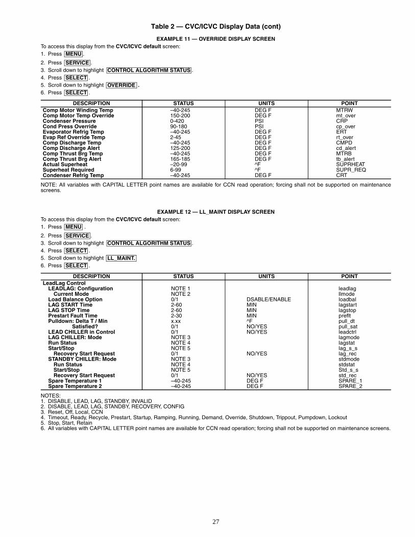
27
Table 2 — CVC/ICVC Display Data (cont)
EXAMPLE 11 — OVERRIDE DISPLAY SCREENTo access this display from the CVC/ICVC default screen:1. Press .
2. Press .3. Scroll down to highlight .4. Press .5. Scroll down to highlight .6. Press .
NOTE: All variables with CAPITAL LETTER point names are available for CCN read operation; forcing shall not be supported on maintenancescreens.
EXAMPLE 12 — LL_MAINT DISPLAY SCREENTo access this display from the CVC/ICVC default screen:1. Press .
2. Press .3. Scroll down to highlight .4. Press .5. Scroll down to highlight 6. Press .
NOTES:1. DISABLE, LEAD, LAG, STANDBY, INVALID2. DISABLE, LEAD, LAG, STANDBY, RECOVERY, CONFIG3. Reset, Off, Local, CCN4. Timeout, Ready, Recycle, Prestart, Startup, Ramping, Running, Demand, Override, Shutdown, Trippout, Pumpdown, Lockout5. Stop, Start, Retain6. All variables with CAPITAL LETTER point names are available for CCN read operation; forcing shall not be supported on maintenance screens.
DESCRIPTION STATUS UNITS POINTComp Motor Winding Temp –40-245 DEG F MTRWComp Motor Temp Override 150-200 DEG F mt_overCondenser Pressure 0-420 PSI CRPCond Press Override 90-180 PSI cp_overEvaporator Refrig Temp –40-245 DEG F ERTEvap Ref Override Temp 2-45 DEG F rt_overComp Discharge Temp –40-245 DEG F CMPDComp Discharge Alert 125-200 DEG F cd_alertComp Thrust Brg Temp –40-245 DEG F MTRBComp Thrust Brg Alert 165-185 DEG F tb_alertActual Superheat –20-99 ^F SUPRHEATSuperheat Required 6-99 ^F SUPR_REQCondenser Refrig Temp –40-245 DEG F CRT
DESCRIPTION STATUS UNITS POINT LeadLag Control
LEADLAG: Configuration NOTE 1 leadlagCurrent Mode NOTE 2 llmode
Load Balance Option 0/1 DSABLE/ENABLE loadbalLAG START Time 2-60 MIN lagstartLAG STOP Time 2-60 MIN lagstopPrestart Fault Time 2-30 MIN prefltPulldown: Delta T / Min x.xx ^F pull_dt
Satisfied? 0/1 NO/YES pull_satLEAD CHILLER in Control 0/1 NO/YES leadctrlLAG CHILLER: Mode NOTE 3 lagmodeRun Status NOTE 4 lagstatStart/Stop NOTE 5 lag_s_s
Recovery Start Request 0/1 NO/YES lag_recSTANDBY CHILLER: Mode NOTE 3 stdmode
Run Status NOTE 4 stdstatStart/Stop NOTE 5 Std_s_sRecovery Start Request 0/1 NO/YES std_rec
Spare Temperature 1 –40-245 DEG F SPARE_1Spare Temperature 2 –40-245 DEG F SPARE_2
MENU
SERVICECONTROL ALGORITHM STATUS
SELECTOVERRIDE
SELECT
MENU
SERVICECONTROL ALGORITHM STATUS
SELECTLL_MAINT.
SELECT
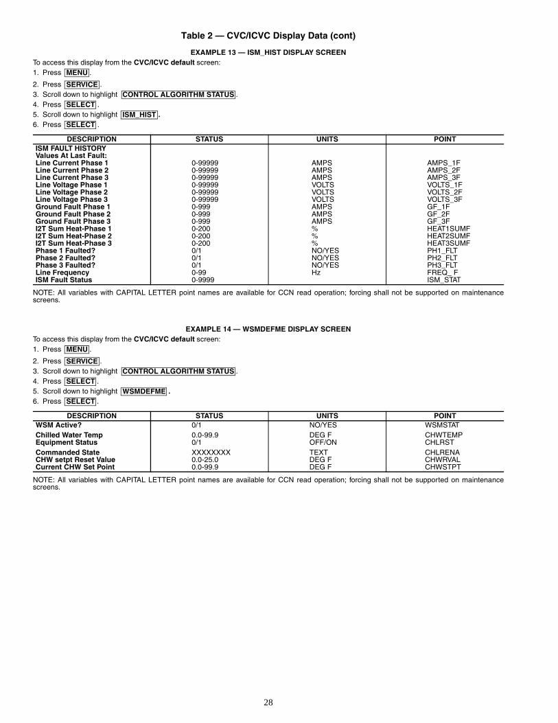
28
Table 2 — CVC/ICVC Display Data (cont)
EXAMPLE 13 — ISM_HIST DISPLAY SCREENTo access this display from the CVC/ICVC default screen:1. Press .
2. Press .3. Scroll down to highlight .4. Press .5. Scroll down to highlight .6. Press .
NOTE: All variables with CAPITAL LETTER point names are available for CCN read operation; forcing shall not be supported on maintenancescreens.
EXAMPLE 14 — WSMDEFME DISPLAY SCREENTo access this display from the CVC/ICVC default screen:1. Press .
2. Press .3. Scroll down to highlight .4. Press .5. Scroll down to highlight .6. Press .
NOTE: All variables with CAPITAL LETTER point names are available for CCN read operation; forcing shall not be supported on maintenancescreens.
DESCRIPTION STATUS UNITS POINT ISM FAULT HISTORYValues At Last Fault:Line Current Phase 1 0-99999 AMPS AMPS_1FLine Current Phase 2 0-99999 AMPS AMPS_2FLine Current Phase 3 0-99999 AMPS AMPS_3FLine Voltage Phase 1 0-99999 VOLTS VOLTS_1FLine Voltage Phase 2 0-99999 VOLTS VOLTS_2FLine Voltage Phase 3 0-99999 VOLTS VOLTS_3FGround Fault Phase 1 0-999 AMPS GF_1FGround Fault Phase 2 0-999 AMPS GF_2FGround Fault Phase 3 0-999 AMPS GF_3FI2T Sum Heat-Phase 1 0-200 % HEAT1SUMFI2T Sum Heat-Phase 2 0-200 % HEAT2SUMFI2T Sum Heat-Phase 3 0-200 % HEAT3SUMFPhase 1 Faulted? 0/1 NO/YES PH1_FLTPhase 2 Faulted? 0/1 NO/YES PH2_FLTPhase 3 Faulted? 0/1 NO/YES PH3_FLTLine Frequency 0-99 Hz FREQ_ FISM Fault Status 0-9999 ISM_STAT
DESCRIPTION STATUS UNITS POINTWSM Active? 0/1 NO/YES WSMSTATChilled Water Temp 0.0-99.9 DEG F CHWTEMPEquipment Status 0/1 OFF/ON CHLRSTCommanded State XXXXXXXX TEXT CHLRENACHW setpt Reset Value 0.0-25.0 DEG F CHWRVALCurrent CHW Set Point 0.0-99.9 DEG F CHWSTPT
MENU
SERVICECONTROL ALGORITHM STATUS
SELECTISM_HIST
SELECT
MENU
SERVICECONTROL ALGORITHM STATUS
SELECTWSMDEFME
SELECT
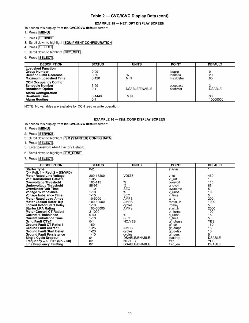
29
Table 2 — CVC/ICVC Display Data (cont)
EXAMPLE 15 — NET_OPT DISPLAY SCREENTo access this display from the CVC/ICVC default screen:1. Press .
2. Press .3. Scroll down to highlight .4. Press .
5. Scroll down to highlight .
6. Press .
NOTE: No variables are available for CCN read or write operation.
EXAMPLE 16 — ISM_CONF DISPLAY SCREENTo access this display from the CVC/ICVC default screen:1. Press .
2. Press .3. Scroll down to highlight .4. Press .5. Enter password (4444 Factory Default).
6. Scroll down to highlight .
7. Press .
DESCRIPTION STATUS UNITS POINT DEFAULT Loadshed FunctionGroup Number 0-99 ldsgrp 0Demand Limit Decrease 0-60 % ldsdelta 20Maximum Loadshed Time 0-120 MIN maxldstm 60CCN Occupancy Config:Schedule Number 3-99 occpcxxe 3Broadcast Option 0-1 DSABLE/ENABLE occbrcst DSABLEAlarm ConfigurationRe-Alarm Time 0-1440 MIN 30Alarm Routing 0-1 10000000
DESCRIPTION STATUS UNITS POINT DEFAULTStarter Type 0-2 starter 1(0 = Full, 1 = Red, 2 = SS/VFD)Motor Rated Line Voltage 200-13200 VOLTS v_fs 460Volt Transformer Ratio:1 1-35 vt_rat 1Overvoltage Threshold 105-115 % overvolt 115Undervoltage Threshold 85-95 % undvolt 85Over/Under Volt Time 1-10 SEC uvuntime 5Voltage % Imbalance 1-10 % v_unbal 10Voltage Imbalance Time 1-10 SEC v_time 5Motor Rated Load Amps 10-5000 AMPS a_fs 200Motor Locked Rotor Trip 100-60000 AMPS motor_lr 1000Locked Rotor Start Delay 1-10 cycles lrdelay 5Starter LRA Rating 100-60000 AMPS start_lr 2000Motor Current CT Ratio:1 3-1000 ct_turns 100Current % Imbalance 5-40 % c_unbal 15Current Imbalance Time 1-10 SEC c_time 5Grnd Fault CT’s? 0-1 NO/YES gf_phase YESGround Fault CT Ratio:1 150 gf_ctr 150Ground Fault Current 1-25 AMPS gf_amps 15Ground Fault Start Delay 1-20 cycles gf_delay 10Ground Fault Persistence 1-10 cycles gf_pers 5Single Cycle Dropout 0/1 DSABLE/ENABLE cycdrop DSABLEFrequency = 60 Hz? (No = 50) 0/1 NO/YES freq YESLine Frequency Faulting 0/1 DSABLE/ENABLE freq_en DSABLE
MENU
SERVICEEQUIPMENT CONFIGURATION
SELECT
NET_OPT
SELECT
MENU
SERVICEISM (STARTER) CONFIG DATA
SELECT
ISM_CONF
SELECT
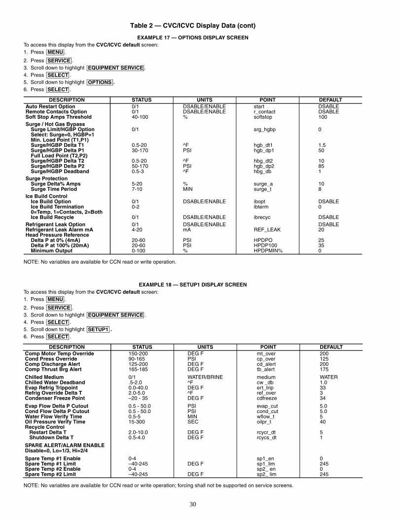
30
Table 2 — CVC/ICVC Display Data (cont)
EXAMPLE 17 — OPTIONS DISPLAY SCREENTo access this display from the CVC/ICVC default screen:1. Press .
2. Press .3. Scroll down to highlight .4. Press .5. Scroll down to highlight .6. Press .
NOTE: No variables are available for CCN read or write operation.
EXAMPLE 18 — SETUP1 DISPLAY SCREENTo access this display from the CVC/ICVC default screen:1. Press .
2. Press .3. Scroll down to highlight .4. Press .5. Scroll down to highlight .6. Press .
NOTE: No variables are available for CCN read or write operation; forcing shall not be supported on service screens.
DESCRIPTION STATUS UNITS POINT DEFAULTAuto Restart Option 0/1 DSABLE/ENABLE start DSABLERemote Contacts Option 0/1 DSABLE/ENABLE r_contact DSABLESoft Stop Amps Threshold 40-100 % softstop 100Surge / Hot Gas Bypass
Surge Limit/HGBP Option 0/1 srg_hgbp 0Select: Surge=0, HGBP=1Min. Load Point (T1,P1)Surge/HGBP Delta T1 0.5-20 ^F hgb_dt1 1.5Surge/HGBP Delta P1 30-170 PSI hgb_dp1 50Full Load Point (T2,P2)Surge/HGBP Delta T2 0.5-20 ^F hbg_dt2 10Surge/HGBP Delta P2 50-170 PSI hgb_dp2 85Surge/HGBP Deadband 0.5-3 ^F hbg_db 1
Surge ProtectionSurge Delta% Amps 5-20 % surge_a 10Surge Time Period 7-10 MIN surge_t 8
Ice Build ControlIce Build Option 0/1 DSABLE/ENABLE ibopt DSABLEIce Build Termination 0-2 ibterm 00=Temp, 1=Contacts, 2=BothIce Build Recycle 0/1 DSABLE/ENABLE ibrecyc DSABLE
Refrigerant Leak Option 0/1 DSABLE/ENABLE DSABLERefrigerant Leak Alarm mA 4-20 mA REF_LEAK 20Head Pressure Reference
Delta P at 0% (4mA) 20-60 PSI HPDPO 25Delta P at 100% (20mA) 20-60 PSI HPDP100 35Minimum Output 0-100 % HPDPMIN% 0
DESCRIPTION STATUS UNITS POINT DEFAULTComp Motor Temp Override 150-200 DEG F mt_over 200Cond Press Override 90-165 PSI cp_over 125Comp Discharge Alert 125-200 DEG F cd_alert 200Comp Thrust Brg Alert 165-185 DEG F tb_alert 175
Chilled Medium 0/1 WATER/BRINE medium WATERChilled Water Deadband .5-2.0 ^F cw _db 1.0Evap Refrig Trippoint 0.0-40.0 DEG F ert_trip 33Refrig Override Delta T 2.0-5.0 ^F ref_over 3Condenser Freeze Point –20 - 35 DEG F cdfreeze 34
Evap Flow Delta P Cutout 0.5 - 50.0 PSI evap_cut 5.0Cond Flow Delta P Cutout 0.5 - 50.0 PSI cond_cut 5.0Water Flow Verify Time 0.5-5 MIN wflow_t 5Oil Pressure Verify Time 15-300 SEC oilpr_t 40Recycle Control Restart Delta T 2.0-10.0 DEG F rcycr_dt 5 Shutdown Delta T 0.5-4.0 DEG F rcycs_dt 1
SPARE ALERT/ALARM ENABLEDisable=0, Lo=1/3, Hi=2/4
Spare Temp #1 Enable 0-4 sp1_en 0Spare Temp #1 Limit –40-245 DEG F sp1_lim 245Spare Temp #2 Enable 0-4 sp2_ en 0Spare Temp #2 Limit –40-245 DEG F sp2_ lim 245
MENU
SERVICEEQUIPMENT SERVICE
SELECTOPTIONS
SELECT
MENU
SERVICEEQUIPMENT SERVICE
SELECTSETUP1
SELECT
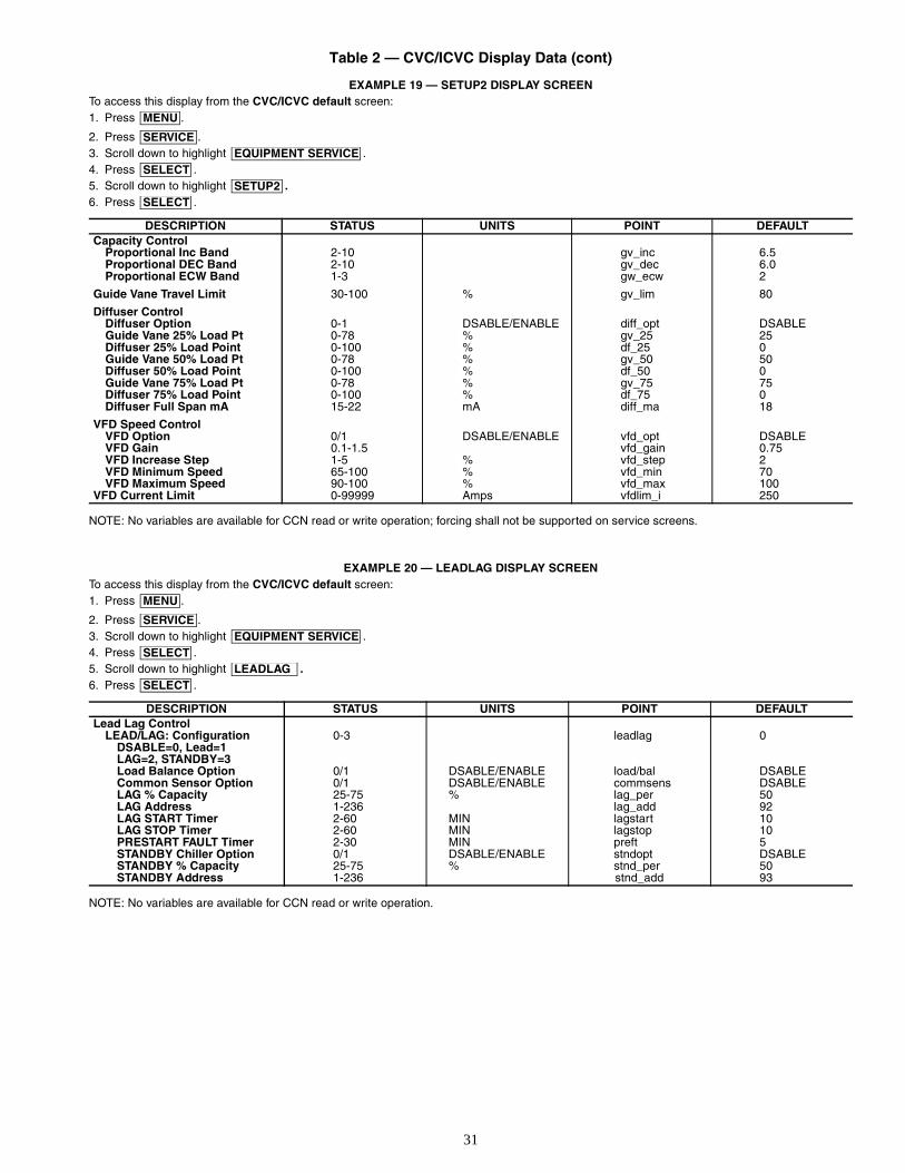
31
Table 2 — CVC/ICVC Display Data (cont)
EXAMPLE 19 — SETUP2 DISPLAY SCREENTo access this display from the CVC/ICVC default screen:1. Press .
2. Press .3. Scroll down to highlight .4. Press .5. Scroll down to highlight .6. Press .
NOTE: No variables are available for CCN read or write operation; forcing shall not be supported on service screens.
EXAMPLE 20 — LEADLAG DISPLAY SCREENTo access this display from the CVC/ICVC default screen:1. Press .
2. Press .3. Scroll down to highlight .4. Press .5. Scroll down to highlight .6. Press .
NOTE: No variables are available for CCN read or write operation.
DESCRIPTION STATUS UNITS POINT DEFAULTCapacity Control
Proportional Inc Band 2-10 gv_inc 6.5Proportional DEC Band 2-10 gv_dec 6.0Proportional ECW Band 1-3 gw_ecw 2
Guide Vane Travel Limit 30-100 % gv_lim 80
Diffuser ControlDiffuser Option 0-1 DSABLE/ENABLE diff_opt DSABLEGuide Vane 25% Load Pt 0-78 % gv_25 25Diffuser 25% Load Point 0-100 % df_25 0Guide Vane 50% Load Pt 0-78 % gv_50 50Diffuser 50% Load Point 0-100 % df_50 0Guide Vane 75% Load Pt 0-78 % gv_75 75Diffuser 75% Load Point 0-100 % df_75 0Diffuser Full Span mA 15-22 mA diff_ma 18
VFD Speed ControlVFD Option 0/1 DSABLE/ENABLE vfd_opt DSABLEVFD Gain 0.1-1.5 vfd_gain 0.75VFD Increase Step 1-5 % vfd_step 2VFD Minimum Speed 65-100 % vfd_min 70VFD Maximum Speed 90-100 % vfd_max 100
VFD Current Limit 0-99999 Amps vfdlim_i 250
DESCRIPTION STATUS UNITS POINT DEFAULTLead Lag Control
LEAD/LAG: Configuration 0-3 leadlag 0DSABLE=0, Lead=1 LAG=2, STANDBY=3Load Balance Option 0/1 DSABLE/ENABLE load/bal DSABLECommon Sensor Option 0/1 DSABLE/ENABLE commsens DSABLELAG % Capacity 25-75 % lag_per 50LAG Address 1-236 lag_add 92LAG START Timer 2-60 MIN lagstart 10LAG STOP Timer 2-60 MIN lagstop 10PRESTART FAULT Timer 2-30 MIN preft 5STANDBY Chiller Option 0/1 DSABLE/ENABLE stndopt DSABLESTANDBY % Capacity 25-75 % stnd_per 50STANDBY Address 1-236 stnd_add 93
MENU
SERVICEEQUIPMENT SERVICE
SELECTSETUP2
SELECT
MENU
SERVICEEQUIPMENT SERVICE
SELECTLEADLAG
SELECT
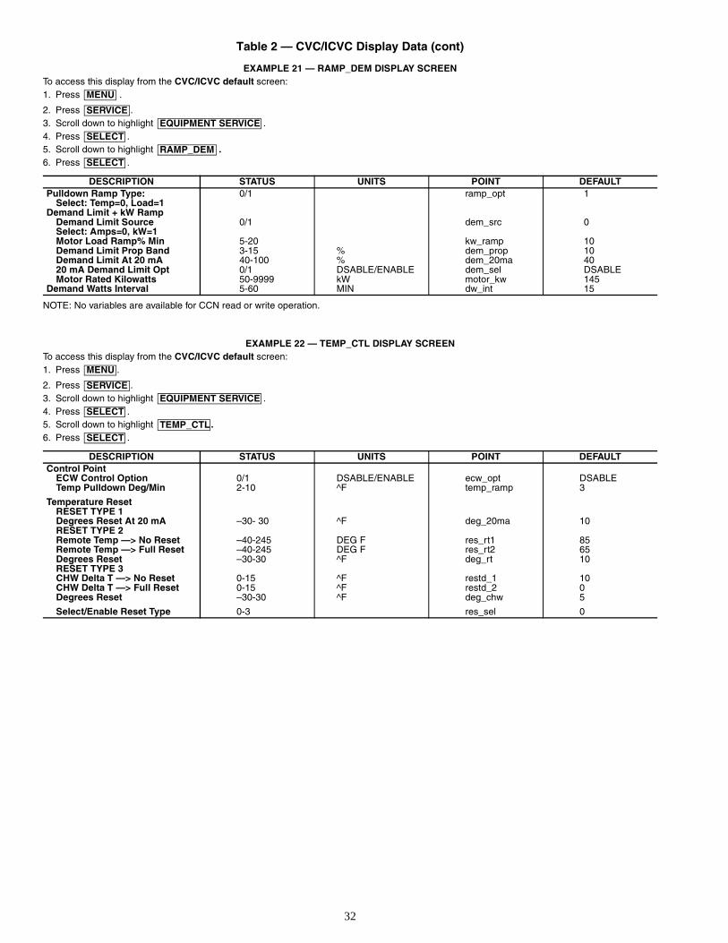
32
Table 2 — CVC/ICVC Display Data (cont)
EXAMPLE 21 — RAMP_DEM DISPLAY SCREENTo access this display from the CVC/ICVC default screen:1. Press .
2. Press .3. Scroll down to highlight .4. Press .5. Scroll down to highlight .6. Press .
NOTE: No variables are available for CCN read or write operation.
EXAMPLE 22 — TEMP_CTL DISPLAY SCREENTo access this display from the CVC/ICVC default screen:1. Press .
2. Press .3. Scroll down to highlight .4. Press .5. Scroll down to highlight .6. Press .
DESCRIPTION STATUS UNITS POINT DEFAULTPulldown Ramp Type: 0/1 ramp_opt 1
Select: Temp=0, Load=1Demand Limit + kW Ramp
Demand Limit Source 0/1 dem_src 0Select: Amps=0, kW=1Motor Load Ramp% Min 5-20 kw_ramp 10Demand Limit Prop Band 3-15 % dem_prop 10Demand Limit At 20 mA 40-100 % dem_20ma 4020 mA Demand Limit Opt 0/1 DSABLE/ENABLE dem_sel DSABLEMotor Rated Kilowatts 50-9999 kW motor_kw 145
Demand Watts Interval 5-60 MIN dw_int 15
DESCRIPTION STATUS UNITS POINT DEFAULTControl Point
ECW Control Option 0/1 DSABLE/ENABLE ecw_opt DSABLETemp Pulldown Deg/Min 2-10 ^F temp_ramp 3
Temperature ResetRESET TYPE 1Degrees Reset At 20 mA –30- 30 ^F deg_20ma 10RESET TYPE 2Remote Temp —> No Reset –40-245 DEG F res_rt1 85Remote Temp —> Full Reset –40-245 DEG F res_rt2 65Degrees Reset –30-30 ^F deg_rt 10RESET TYPE 3CHW Delta T —> No Reset 0-15 ^F restd_1 10CHW Delta T —> Full Reset 0-15 ^F restd_2 0Degrees Reset –30-30 ^F deg_chw 5
Select/Enable Reset Type 0-3 res_sel 0
MENU
SERVICEEQUIPMENT SERVICE
SELECTRAMP_DEM
SELECT
MENU
SERVICEEQUIPMENT SERVICE
SELECTTEMP_CTL
SELECT
33
PIC II System FunctionsNOTE: Words not part of paragraph headings and printed in allcapital letters can be viewed on the CVC/ICVC (e.g., LOCAL,CCN, RUNNING, ALARM, etc.). Words printed both in allcapital letters and italics can also be viewed on the CVC/ICVCand are parameters (CONTROL MODE, TARGET GUIDEVANE POS, etc.) with associated values (e.g., modes, tempera-tures, pressures, percentages, on, off, enable, disable, etc.).Words printed in all capital letters and in a box represent soft-keys on the CVC/ICVC (e.g., and ). SeeTable 2 for examples of the type of information that can appearon the CVC/ICVC screens. Figures 14-20 give an overview ofCVC/ICVC operations and menus.CAPACITY CONTROL FIXED SPEED — The PIC II con-trols the chiller capacity by modulating the inlet guide vanes inresponse to chilled water temperature deviation from the CON-TROL POINT. The CONTROL POINT may be changed by aCCN network device or is determined by the PIC II adding anyactive chilled water reset to the SET POINT. The PIC II usesthe PROPORTIONAL INC (Increase) BAND, PROPOR-TIONAL DEC (Decrease) BAND, and the PROPORTIONALECW (Entering Chilled Water) GAIN to determine how fast orslow to respond. CONTROL POINT may be viewed or over-ridden from the MAINSTAT screen.CAPACITY CONTROL VFD — The PIC II controls themachine capacity by modulating the motor speed and inletguide vanes in response to chilled water temperature deviationfrom the CONTROL POINT. The controller will maintain thehighest inlet guide vane setting at the lowest speed to maxi-mize efficiency while avoiding surge. The CONTROL POINTmay be changed by a CCN network device or is determined bythe PIC II adding any active chilled water reset to the to theSET POINT. CONTROL POINT may be viewed or overriddenfrom the MAINSTAT screen. The PIC II uses the PROPOR-TIONAL INC (Increase) BAND, PROP DEC (Decrease)BAND, and the PROPORTIONAL ECW (Entering ChilledWater) GAIN to determine how fast or slow it takes the systemto respond. The VFD GAIN allows for additional adjustment ofthe VFD response. At start-up, the inlet guide vanes (IGV)start in the closed position and the VFD ramps to its minimumspeed setting.
The PIC II controller then initiates the Capacity Control al-gorithm to maintain the chilled water temperature at the CON-TROL POINT. During operation when the CONTROL POINTis not met, the controller will establish a GUIDE VANE DELTAwhich will either affect a percentage change to the GUIDEVANES or the VFD TARGET SPEED. Any change that will bemade to the IGV position or the VFD SPEED will depend onwhether the GUIDE VANE DELTA is positive or negative, andthe status of the Surge Control Algorithm. The Surge ControlAlgorithm determines if the chiller should operate in NormalMode or Surge Prevention Mode. The logic for how the IGV’sand VFD SPEED will be affected by the GUIDE VANE DEL-TA and the Surge Control Algorithm can be seen below:
Normal Control mode occurs when ACTIVE DELTA T >SURGE/HGBP DELTA T.
Surge Prevention Mode occurs when ACTIVE DELTA T≤ SURGE/HGBP DELTA T.
The TARGET VFD SPEED, ACTUAL VFD SPEED and theVFD GAIN can be viewed and modified in the CAPACITY
display screen. The TARGET VFD SPEED can be manuallyoverridden by the operator from the COMPRESS screen. TheVFD MINIMUM SPEED, MAXIMUM SPEED, VFD GAINand INCREASE STEP can be viewed and modified in theSETUP2 display screen. TARGET and ACTUAL VFD SPEEDcan be viewed in the COMPRESS screen.ECW CONTROL OPTION — If this option is enabled, thePIC II uses the ENTERING CHILLED WATER temperature tomodulate the vanes instead of the LEAVING CHILLEDWATER temperature. The ECW CONTROL OPTION may beviewed on the TEMP_CTL screen, which is accessed from theEQUIPMENT SERVICE screen.CONTROL POINT DEADBAND — This is the tolerancerange on the chilled water/brine temperature control point. Ifthe water temperature goes outside the CHILLED WATERDEADBAND, the PIC II opens or closes the guide vanes untilthe temperature is within tolerance. The PIC II may be config-ured with a 0.5 to 2 F (0.3 to 1.1 C) deadband. CHILLEDWATER DEADBAND may be viewed or modified on theSETUP1 screen, which is accessed from the EQUIPMENTSERVICE table.
For example, a 1° F (0.6° C) deadband setting controls thewater temperature within ±0.5° F (0.3° C) of the control point.This may cause frequent guide vane movement if the chilledwater load fluctuates frequently. A value of 1° F (0.6° C) is thedefault setting.DIFFUSER CONTROL — On 19XR FRAME sizes 4 and5 compressors equipped with a variable discharge diffuser, thePIC II adjusts the diffuser actuator position (DIFFUSERACTUATOR on the COMPRESS screen) to correspond to theactual guide vane position (ACTUAL GUIDE VANE POS onthe COMPRESS screen).
The diffuser control can be enabled or disabled from theSETUP2 screen. See Table 2, Example 19. In addition, the dif-fuser and guide vane load points may be viewed and modifiedfrom this screen. These points must be correct for the compres-sor size. The diffuser opening can be incremented from fullyopen to completely closed. A 0% setting is fully open; a 100%setting is completely closed. To obtain the proper settings forDiffuser Control, contact a Carrier Engineering representative.PROPORTIONAL BANDS AND GAIN — Proportional bandis the rate at which the guide vane position is corrected in pro-portion to how far the chilled water/brine temperature is fromthe control point. Proportional gain determines how quickly theguide vanes react to how quickly the temperature is movingfrom the CONTROL POINT. The proportional bands and gainmay be viewed or modified from the SETUP2 screen, which isaccessed from the EQUIPMENT SERVICE table.The Proportional Band — There are two response modes, onefor temperature response above the control point, the other forthe response below the control point.
The temperature response above the control point is calledthe PROPORTIONAL INC BAND, and it can slow or quickenguide vane response to chilled water/brine temperatures abovethe DEADBAND. The PROPORTIONAL INC BAND can beadjusted from a setting of 2 to 10; the default setting is 6.5.
The response below the control point is called the PRO-PORTIONAL DEC BAND, and it can slow or quicken theguide vane response to chilled water temperature below thedeadband plus the control point. The PROPORTIONAL DECBAND can be adjusted on the CVC/ICVC from a setting of 2 to10. The default setting is 6.0.NOTE: Increasing either of these settings causes the guidevanes to respond more slowly than they would at a lowersetting.
GUIDE VANEDELTA
NORMALCONTROL
MODE
SURGEPREVENTION
MODEIGV VFD IGV VFD
From +0.2 to +2.0 1st 2nd 2nd 1stFrom –0.2 to –2.0 2nd 1st 1st —
ENTER EXIT
34
The PROPORTIONAL ECW GAIN can be adjusted on theCVC/ICVC display for values of 1, 2, or 3; the default settingis 2. Increase this setting to increase guide vane response to achange in entering chilled water temperature.DEMAND LIMITING — The PIC II responds to the ACTIVEDEMAND LIMIT set point by limiting the opening of theguide vanes. It compares the ACTIVE DEMAND LIMIT setpoint to the DEMAND LIMIT SOURCE (either the AVERAGELINE CURRENT or the MOTOR KW). Depending on how thecontrol is configured. DEMAND LIMIT SOURCE is on theRAMP_DEM screen. The default source is the compressormotor current.CHILLER TIMERS — The PIC II maintains 2 run timeclocks, known as COMPRESSOR ONTIME and SERVICEONTIME. COMPRESSOR ONTIME indicates the total life-time compressor run hours. This timer can register up to500,000 hours before the clock turns back to zero. The SER-VICE ONTIME is a reset table timer that can be used to indi-cate the hours since the last service visit or any other event.The time can be changed from the CVC/ICVC to whatevervalue is desired. This timer can register up to 32,767 hoursbefore it rolls over to zero.
The chiller also maintains a start-to-start timer and a stop-to-start timer. These timers limit how soon the chiller can bestarted. START INHIBIT TIMER is displayed on the MAIN-STAT screen. See the Start-Up/Shutdown/Recycle Sequencesection, page 46, for more information on this topic.OCCUPANCY SCHEDULE — The chiller schedule, de-scribed in the Time Schedule Operation section (page 20), de-termines when the chiller can run. Each schedule consists offrom 1 to 8 occupied or unoccupied time periods, set by the op-erator. The chiller can be started and run during an occupiedtime period (when OCCUPIED? is set to YES on the MAIN-STAT display screen). It cannot be started or run during an un-occupied time period (when OCCUPIED? is set to NO on theMAINSTAT display screen). These time periods can be set foreach day of the week and for holidays. The day begins with0000 hours and ends with 2400 hours. The default setting forOCCUPIED? is YES, unless an unoccupied time period is ineffect.
These schedules can be set up to follow a building’s occu-pancy schedule, or the chiller can be set so to run 100% of thetime, if the operator wishes. The schedules also can be by-passed by forcing the CHILLER START/STOP parameter onthe MAINSTAT screen to START. For more information onforced starts, see Local Start-Up, page 46.
The schedules also can be overridden to keep the chiller inan occupied state for up to 4 hours, on a one time basis. See theTime Schedule Operation section, page 20.
Figure 19 shows a schedule for a typical office buildingwith a 3-hour, off-peak, cool-down period from midnight to3 a.m., following a weekend shutdown. Holiday periods are inan unoccupied state 24 hours per day. The building operatesMonday through Friday, 7:00 a.m. to 6:00 p.m., and Saturdaysfrom 6:00 a.m. to 1:00 p.m. This schedule also includes theMonday midnight to 3:00 a.m. weekend cool-down schedule.NOTE: This schedule is for illustration only and is notintended to be a recommended schedule for chiller operation.
Whenever the chiller is in the LOCAL mode, it uses Occu-pancy Schedule 01 (OCCPC01S). When the chiller is in the
ICE BUILD mode, it uses Occupancy Schedule 02(OCCPC02S). When the chiller is in CCN mode, it usesOccupancy Schedule 03 (OCCPC03S).
The CCN SCHEDULE NUMBER is configured on theNET_OPT display screen, accessed from the EQUIPMENTCONFIGURATION table. See Table 2, Example 15. SCHED-ULE NUMBER can be changed to any value from 03 to 99. Ifthis number is changed on the NET_OPT screen, the operatormust go to the ATTACH TO NETWORK DEVICE screen toupload the new number into the SCHEDULE screen. SeeFig. 18.
Safety Controls — The PIC II monitors all safety controlinputs and, if required, shuts down the chiller or limits theguide vanes to protect the chiller from possible damage fromany of the following conditions:• high bearing temperature• high motor winding temperature• high discharge temperature• low discharge superheat*• low oil pressure• low cooler refrigerant temperature/pressure• condenser high pressure or low pressure• inadequate water/brine cooler and condenser flow• high, low, or loss of voltage• ground fault• voltage imbalance• current imbalance• excessive motor acceleration time• excessive starter transition time• lack of motor current signal• excessive motor amps• excessive compressor surge• temperature and transducer faults*Superheat is the difference between saturation temperatureand sensible temperature. The high discharge temperaturesafety measures only sensible temperature.
Starter faults or optional protective devices within the startercan shut down the chiller. The protective devices you have foryour application depend on what options were purchased.
If the PIC II control initiates a safety shutdown, it displaysthe reason for the shutdown (the fault) on the CVC/ICVC dis-play screen along with a primary and secondary message, ener-gizes an alarm relay in the starter, and blinks the alarm light onthe control panel. The alarm is stored in memory and can beviewed on the ALARM HISTORY and ISM_HIST screens onthe CVC/ICVC, along with a message for troubleshooting. Ifthe safety shutdown was also initiated by a fault detected in themotor starter, the conditions at the time of the fault will bestored in ISM_HIST.
To give more precise information or warnings on thechiller’s operating condition, the operator can define alert lim-its on various monitored inputs. Safety contact and alert limitsare defined in Table 3. Alarm and alert messages are listed inthe Troubleshooting Guide section, page 76.
If compressor motor overload occurs, check the motor forgrounded or open phases before attempting a restart.
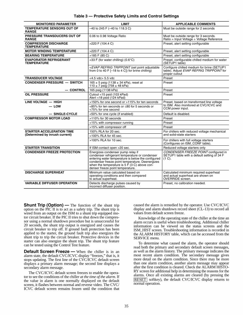
35
Table 3 — Protective Safety Limits and Control Settings
Shunt Trip (Option) — The function of the shunt tripoption on the PIC II is to act as a safety trip. The shunt trip iswired from an output on the ISM to a shunt trip equipped mo-tor circuit breaker. If the PIC II tries to shut down the compres-sor using a normal shutdown procedure but is unsuccessful for20 seconds, the shunt trip output is energized and causes thecircuit breaker to trip off. If ground fault protection has beenapplied to the starter, the ground fault trip also energizes theshunt trip to trip the circuit breaker. Protective devices in thestarter can also energize the shunt trip. The shunt trip featurecan be tested using the Control Test feature.
Default Screen Freeze — When the chiller is in analarm state, the default CVC/ICVC display “freezes,” that is, itstops updating. The first line of the CVC/ICVC default screendisplays a primary alarm message; the second line displays asecondary alarm message.
The CVC/ICVC default screen freezes to enable the opera-tor to see the conditions of the chiller at the time of the alarm. Ifthe value in alarm is one normally displayed on the defaultscreen, it flashes between normal and reverse video. The CVC/ICVC default screen remains frozen until the condition that
caused the alarm is remedied by the operator. Use CVC/ICVCdisplay and alarm shutdown record sheet (CL-13) to record allvalues from default screen freeze.
Knowledge of the operating state of the chiller at the time analarm occurs is useful when troubleshooting. Additional chillerinformation can be viewed on the status screens and theISM_HIST screen. Troubleshooting information is recorded inthe ALARM HISTORY table, which can be accessed from theSERVICE menu.
To determine what caused the alarm, the operator shouldread both the primary and secondary default screen messages,as well as the alarm history. The primary message indicates themost recent alarm condition. The secondary message givesmore detail on the alarm condition. Since there may be morethan one alarm condition, another alarm message may appearafter the first condition is cleared. Check the ALARM HISTO-RY screen for additional help in determining the reasons for thealarms. Once all existing alarms are cleared (by pressing the
softkey), the default CVC/ICVC display returns tonormal operation.
MONITORED PARAMETER LIMIT APPLICABLE COMMENTSTEMPERATURE SENSORS OUT OFRANGE
–40 to 245 F (–40 to 118.3 C) Must be outside range for 2 seconds
PRESSURE TRANSDUCERS OUT OFRANGE
0.06 to 0.98 Voltage Ratio Must be outside range for 3 seconds.Ratio = Input Voltage ÷ Voltage Reference
COMPRESSOR DISCHARGETEMPERATURE
>220 F (104.4 C) Preset, alert setting configurable
MOTOR WINDING TEMPERATURE >220 F (104.4 C) Preset, alert setting configurableBEARING TEMPERATURE >185 F (85 C) Preset, alert setting configurableEVAPORATOR REFRIGERANT TEMPERATURE
<33 F (for water chilling) (0.6°C) Preset, configurable chilled medium for water (SETUP1 table)
<EVAP REFRIG TRIPPOINT (set point adjustable from 0 to 40 F [–18 to 4 C]) for brine chilling)
Configure chilled medium for brine (SETUP1 table). Adjust EVAP REFRIG TRIPPOINT for proper cutout
TRANSDUCER VOLTAGE <4.5 vdc> 5.5 vdc PresetCONDENSER PRESSURE — SWITCH 165 ± 5 psig (1138 ± 34 kPa), reset at
110 ± 7 psig (758 ± 48 kPa)Preset
— CONTROL 165 psig (1138 kPa) PresetOIL PRESSURE Cutout <15 psid (103 kPad)
Alert <18 psid (124 kPad)Preset
LINE VOLTAGE — HIGH >150% for one second or >115% for ten seconds Preset, based on transformed line voltageto ISM. Also monitored at CVC/ICVC and CCM power input.
— LOW <85% for ten seconds or ≤80 for 5 seconds or <75% for one second
— SINGLE-CYCLE <50% for one cycle (if enabled) Default is disabled.COMPRESSOR MOTOR LOAD >110% for 30 seconds Preset
<15% with compressor running Preset>15% with compressor off Preset
STARTER ACCELERATION TIME(Determined by inrush current)
150% RLA for 20 sec. For chillers with reduced voltage mechanical and solid-state starters>100% RLA for 45 sec.
>100% RLA for 10 sec. For chillers with full voltage starters (Configures on ISM_CONF table).
STARTER TRANSITION If ISM contact open >20 sec. Reduced voltage starters onlyCONDENSER FREEZE PROTECTION Energizes condenser pump relay if
condenser refrigerant temperature or condenser entering water temperature is below the configured condenser freeze point temperature. Deenergizes when the temperature is 5 F (3 C) above con-denser freeze point temperature.
CONDENSER FREEZE POINT configured in SETUP1 table with a default setting of 34 F(1 C).
DISCHARGE SUPERHEAT Minimum value calculated based onoperating conditions and then comparedto actual superheat.
Calculated minimum required superheatand actual superheat are shown onOVERRIDE screen.
VARIABLE DIFFUSER OPERATION Detects discharge pulses caused byincorrect diffuser position.
Preset, no calibration needed.
RESET
36
Ramp Loading — The ramp loading control slows downthe rate at which the compressor loads up. This control can pre-vent the compressor from loading up during the short period oftime when the chiller is started and the chilled water loop has tobe brought down to CONTROL POINT. This helps reduceelectrical demand charges by slowly bringing the chilled waterto CONTROL POINT. The total power draw during this periodremains almost unchanged.
There are two methods of ramp loading with the PIC II.Ramp loading can be based on chilled water temperature or onmotor load. Either method is selected from the RAMP__DEMscreen.
1. Temperature ramp loading (TEMP PULLDOWN DEG/MIN) limits the degrees per minute rate at which eitherleaving chilled water or entering chilled water tempera-ture decreases. This rate is configured by the operator onthe TEMP_CTL screen. The lowest temperature ramprate will also be used if chiller power has been off for3 hours or more (even if the motor ramp load is selectedas the ramp loading method).
2. Motor load ramp loading (LOAD PULLDOWN) limitsthe degrees per minute rate at which the compressor mo-tor current or compressor motor load increases. TheLOAD PULLDOWN rate is configured by the operatoron the RAMP_DEM screen in amps or kilowatts. Thepoint name is MOTOR LOAD RAMP%/MIN.
If kilowatts is selected for the DEMAND LIMIT SOURCE,the MOTOR RATED KILOWATTS must be entered (informa-tion found on the chiller Requisition form).
The TEMP PULLDOWN DEG/MIN may be viewed ormodified on the TEMP_CTL screen which is accessed fromthe EQUIPMENT SERVICE screen. PULLDOWN RAMPTYPE, DEMAND LIMIT SOURCE, and MOTOR LOADRAMP %/MIN may be viewed or modified on theRAMP_DEM screen.
Capacity Override (Table 4) — Capacity overrides canprevent some safety shutdowns caused by exceeding the motoramperage limit, refrigerant low temperature safety limit, motorhigh temperature safety limit, and condenser high pressurelimit. In all cases there are 2 stages of compressor vane control.
1. The vanes are prevented from opening further, and thestatus line on the CVC/ICVC indicates the reason for theoverride.
2. The vanes are closed until the condition decreases to be-low the first step set point. Then the vanes are released tonormal capacity control.
Whenever the motor current demand limit set point(ACTIVE DEMAND LIMIT) is reached, it activates a capacityoverride, again, with a 2-step process. Exceeding 110% of therated load amps for more than 30 seconds will initiate a safetyshutdown.
The compressor high lift (surge prevention) set point willcause a capacity override as well. When the surge preventionset point is reached, the controller normally will only preventthe guide vanes from opening. If so equipped, the hot gas by-pass valve will open instead of holding the vanes. See theSurge Prevention Algorithm section, page 39.
High Discharge Temperature Control — If thedischarge temperature increases above 160 F (71.1 C), theguide vanes are proportionally opened to increase gas flowthrough the compressor. If the leaving chilled water tempera-ture is then brought 5° F (2.8° C) below the control set pointtemperature, the PIC II will bring the chiller into the recyclemode.
Oil Sump Temperature Control — The oil sumptemperature control is regulated by the PIC II, which uses theoil heater relay when the chiller is shut down.
As part of the pre-start checks executed by the controls, theoil sump temperature (OIL SUMP TEMP) is compared to thecooler refrigerant temperature (EVAPORATOR REFRIGTEMP). If the difference between these 2 temperatures is 50 F(27.8 C) or less, the start-up will be delayed until the oil tem-perature is 50 F (27.8 C) or more. Once this temperature is con-firmed, the start-up continues.
The oil heater relay is energized whenever the chiller com-pressor is off and the oil sump temperature is less than 140 F(60.0 C) or the oil sump temperature is less than the cooler re-frigerant temperature plus 53° F (11.7° C). The oil heater isturned off when the oil sump temperature is either• more than 152 F (66.7 C), or• more than 142 F (61.1 C) and more than the cooler
refrigerant temperature plus 55° F (12.8° C).The oil heater is always off during start-up or when the
compressor is running.The oil pump is also energized during the time the oil is be-
ing heated (for 60 seconds at the end of every 30 minutes).
Oil Cooler — The oil must be cooled when the compres-sor is running. This is accomplished through a small, plate-typeheat exchanger (also called the oil cooler) located behind theoil pump. The heat exchanger uses liquid condenser refrigerantas the cooling liquid. Refrigerant thermostatic expansionvalves (TXVs) regulate refrigerant flow to control the oil tem-perature entering the bearings. The bulbs for the expansionvalves are strapped to the oil supply line leaving the heat ex-changer, and the valves are set to maintain 110 F (43 C).NOTE: The TXVs are not adjustable. The oil sump tempera-ture may be at a lower temperature during compressoroperations.
Remote Start/Stop Controls — A remote device, suchas a timeclock that uses a set of contacts, may be used to startand stop the chiller. However, the device should not be pro-grammed to start and stop the chiller in excess of 2 or 3 timesevery 12 hours. If more than 8 starts in 12 hours (the STARTSIN 12 HOURS parameter on the MAINSTAT screen) occur, anexcessive starts alarm displays, preventing the chiller fromstarting. The operator must press the softkey on theCVC/ICVC to override the starts counter and start the chiller.If the chiller records 12 starts (excluding recycle starts) in asliding 12-hour period, it can be restarted only by pressing the
softkey followed by the or softkey.This ensures that, if the automatic system is malfunctioning,the chiller will not repeatedly cycle on and off. If the automaticrestart after a power failure option (AUTO RESTART OPTIONon the OPTIONS screen) is not activated when a power failureoccurs, and if the remote contact is closed, the chiller will indi-cate an alarm because of the loss of voltage.
The contacts for remote start are wired into the starter at ter-minal strip J2, terminals 5 and 6 on the ISM. See the certifieddrawings for further details on contact ratings. The contactsmust have 24 vac dry contact rating.
Spare Safety Inputs — Normally closed (NC) discreteinputs for additional field-supplied safeties may be wired to thespare protective limits input channel in place of the factory-installed jumper. (Wire multiple inputs in series.) The openingof any contact will result in a safety shutdown and a display onthe CVC/ICVC. Refer to the certified drawings for safety con-tact ratings.
Analog temperature sensors may also be added to the mod-ule (SPARE TEMP #1 and #2). The analog temperature sen-sors may be configured to cause an alert or alarm on the CCNnetwork. The alert will not shut the chiller down. Configuringfor alarm state will cause the chiller to shut down.
RESET
RESET LOCAL CCN
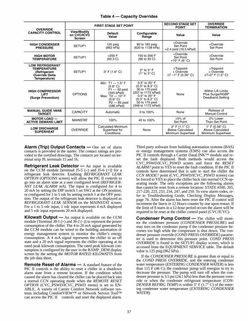
37
Table 4 — Capacity Overrides
Alarm (Trip) Output Contacts — One set of alarmcontacts is provided in the starter. The contact ratings are pro-vided in the certified drawings. The contacts are located on ter-minal strip J9, terminals 15 and 16.
Refrigerant Leak Detector — An input is availableon the CCM module [terminal J5-5 (–) and J5-6 (+)] for arefrigerant leak detector. Enabling REFRIGERANT LEAKOPTION (OPTIONS screen) will allow the PIC II controls togo into an alarm state at a user configured level (REFRIGER-ANT LEAK ALARM mA). The input is configured for 4 to20 mA by setting the DIP switch 1 on SW2 at the ON position,or configured for 1 to 5 vdc by setting switch 1 at the OFF posi-tion. The output of the refrigerant leak detector is displayed asREFRIGERANT LEAK SENSOR on the MAINSTAT screen.For a 1 to 5 vdc input, 1 vdc input represents 4 mA displayedand 5 vdc input represents 20 mA displayed.
Kilowatt Output — An output is available on the CCMmodule [Terminal J8-1 (+) and J8-2 (–)] to represent the powerconsumption of the chiller. The 4 to 20 mA signal generated bythe CCM module can be wired to the building automation orenergy management system to monitor the chiller’s energyconsumption. A 4 mA signal represents the chiller in an offstate and a 20 mA signal represents the chiller operating at itsrated peak kilowatt consumption. The rated peak kilowatt con-sumption is configured by the user in the RAMP_DEM displayscreen by the setting the MOTOR RATED KILOWATTS fromthe job data sheet.
Remote Reset of Alarms — A standard feature of thePIC II controls is the ability to reset a chiller in a shutdownalarm state from a remote location. If the condition whichcaused the alarm has cleared the chiller can be placed back intoa normal CCN operating mode when the REMOTE RESETOPTION (CVC_PSWD/ICVC_PSWD menu) is set to EN-ABLE. A variety of Carrier Comfort Network software sys-tems including ComfortVIEW™ or Network Service Tool™can access the PIC II controls and reset the displayed alarm.
Third party software from building automation systems (BAS)or energy management systems (EMS) can also access thePIC II controls through a Carrier DataLINK™ module and re-set the fault displayed. Both methods would access theCVC_PSWD/ICVC_PSWD screen and force the RESETALARM? point to YES to reset the fault condition. If the PIC IIcontrols have determined that is safe to start the chiller theCCN MODE? point (CVC_PSWD/ICVC_PSWD screen) canbe forced to YES to place the chiller back into normal CCN op-erating mode. The only exceptions are the following alarmsthat cannot be reset from a remote location: STATE #100, 205,217-220, 223, 233, 234, 247, and 250. To view alarm codes, re-fer to Troubleshooting Guide, Checking Display Messages,page 76. After the alarm has been reset the PIC II control willincrement the Starts in 12 Hours counter by one upon restart. Ifthe limit of 8 starts in a 12-hour period occurs the alarm will berequired to be reset at the chiller control panel (CVC/ICVC).
Condenser Pump Control — The chiller will moni-tor the condenser pressure (CONDENSER PRESSURE) andmay turn on the condenser pump if the condenser pressure be-comes too high while the compressor is shut down. The con-denser pressure override (COND PRESS OVERRIDE) parame-ter is used to determine this pressure point. COND PRESSOVERRIDE is found in the SETUP1 display screen, which isaccessed from the EQUIPMENT SERVICE table. The defaultvalue is 125 psig (862 kPa).
If the CONDENSER PRESSURE is greater than or equal tothe COND PRESS OVERRIDE, and the entering condenserwater temperature (ENTERING CONDENSER WATER) is lessthan 115 F (46 C), the condenser pump will energize to try todecrease the pressure. The pump will turn off when the con-denser pressure is 3.5 psi (24.1 kPa) less than the pressure over-ride or when the condenser refrigerant temperature (CON-DENSER REFRIG TEMP) is within 3° F (1.7° C) of the enter-ing condenser water temperature (ENTERING CONDENSERWATER).
OVERRIDECAPACITY CONTROL
FIRST STAGE SET POINT SECOND STAGE SET POINT
OVERRIDE TERMINATION
View/Modifyon CVC/ICVC
Screen
DefaultValue
ConfigurableRange Value Value
HIGH CONDENSERPRESSURE SETUP1 125 psig
(862 kPa)90 to 165 psig
(620 to 1138 kPa)
>OverrideSet Point
+2.4 psid (16.5 kPad)
<OverrideSet Point
HIGH MOTORTEMPERATURE SETUP1 >200 F
(93.3 C)150 to 200 F(66 to 93 C)
>OverrideSet Point
+10° F (6° C)
<OverrideSet Point
LOW REFRIGERANTTEMPERATURE
(RefrigerantOverride DeltaTemperature)
SETUP1 3° F (1.6° C) 2° to 5° F(1° to 3° C)
≤Trippoint+ Override
∆T –1° F (0.56° C)
>Trippoint+ Override
∆T+2° F (1.2° C)
HIGH COMPRESSORLIFT
(Surge Prevention)OPTIONS
Min: T1 — 1.5° F(0.8° C)P1 — 50 psid(345 kPad)
Max: T2 — 10° F(5.6° C)P2 — 85 psid(586 kPad)
0.5° to 20° F(0.3° to 8.3° C)30 to 170 psid
(207 to 1172 kPad)0.5° to 20° F
(0.3° to 8.3° C)50 to 170 psid
(348 to 1172 kPad)
NoneWithin Lift Limits
Plus Surge/HGBPDeadband Setting
MANUAL GUIDE VANETARGET CAPACITY Automatic 0 to 100% None Release of
Manual Control
MOTOR LOAD —ACTIVE DEMAND LIMIT MAINSTAT 100% 40 to 100% ≥5% of
Set Point2% Lower
Than Set Point
LOW DISCHARGESUPERHEAT OVERRIDE
Calculated MinimumSuperheat for
ConditionsNone
2° F (1.1° C)Below Calculated
Minimum Superheat
1° F (0.56° C)Above Calculated
Minimum Superheat
38
Condenser Freeze Prevention — This control algo-rithm helps prevent condenser tube freeze-up by energizing thecondenser pump relay. The PIC II controls the pump and, bystarting it, helps to prevent the water in the condenser fromfreezing. The PIC II can perform this function whenever thechiller is not running except when it is either actively in pump-down or in pumpdown/lockout with the freeze preventiondisabled.
When the CONDENSER REFRIG TEMP is less than orequal to the CONDENSER FREEZE POINT, the CONDENS-ER WATER PUMP is energized until the CONDENSER RE-FRIG TEMP is greater than the CONDENSER FREEZEPOINT plus 5° F (2.7° C) and the ENTERING CONDENSERWATER TEMPERATURE is less than or equal to the CON-DENSER FREEZE POINT. An alarm is generated if the chilleris in PUMPDOWN mode and the pump is energized. An alertis generated if the chiller is not in PUMPDOWN mode and thepump is energized. If the chiller is in RECYCLE SHUT-DOWN mode, the mode will transition to a non-recycleshutdown.
Evaporator Freeze Protection (ICVC only) — Arefrigerant temperature sensor is installed at the bottom of thecooler to provide redundant freeze protection. In place of thecooler and condenser water pressure transducer inputs on theCCM is a 4.3k ohm resister and a jumper lead. When theEVAPORATOR REFRIGERANT TEMPERATURE is lessthan the EVAP REFRIG TRIPPOINT plus the REFRIGOVERRIDE DELTA T (configurable from 2° to 5°), state 122will be displayed and a capacity override will occur. If theEVAPORATOR REFRIG TEMP is equal to or less than theEVAP Refrig TRIPPOINT, Protective Limit ALARM STATE232 will be displayed and the unit will shut down.
Tower Fan Relay Low and High — Low condenserwater temperature can cause the chiller to shut down when re-frigerant temperature is low. The tower fan relays, located inthe starter, are controlled by the PIC II to energize and deener-gize as the pressure differential between cooler and condenservessels changes. This prevents low condenser water tempera-ture and maximizes chiller efficiency. The tower fan relay canonly accomplish this if the relay has been added to the coolingtower temperature controller.
The tower fan relay low is turned on whenever the condens-er water pump is running, flow is verified, and the differencebetween cooler and condenser pressure is more than 30 psid(207 kPad) for entering condenser water temperature greaterthan 65 F (18.3 C).
The tower fan relay low is turned off when the condenserpump is off, flow is stopped, or the cooler refrigerant tempera-ture is less than the override temperature for ENTERING CON-DENSER WATER temperature less than 62 F (16.7 C), or thedifferential pressure is less than 25 psid (172.4 kPad) for enter-ing condenser water less than 80 F (27 C).
The tower fan relay high is turned on whenever thecondenser water pump is running, flow is verified and the dif-ference between cooler and condenser pressure is more than35 psid (241.3 kPa) for entering condenser water temperaturegreater than the TOWER FAN HIGH SETPOINT (SETPOINTmenu, default 75 F [23.9 C]).
The tower fan relay high is turned off when the condenserpump is off, flow is stopped, or the cooler refrigerant tempera-ture is less than the override temperature and ENTERINGCONDENSER WATER is less than 70 F (21.1 C), or the differ-ence between cooler and condenser pressure is less than28 Psid (193 kPa), or ENTERING CONDENSER WATERtemperature is less than TOWER FAN HIGH SETPOINTminus 3 F (–16.1 C).
The TOWER FAN RELAY LOW and HIGH parameters areaccessed from the STARTUP screen.
Auto. Restart After Power Failure — This optionmay be enabled or disabled and may be viewed or modified onthe OPTIONS screen, which is accessed from the EQUIP-MENT CONFIGURATION table. If the AUTO. RESTARTOPTION is enabled, the chiller will start up automatically after apower failure has occurred (after a single cycle dropout; low,high, or loss of voltage; and the power is within ± 15% of nor-mal). The 15- and 5-minute inhibit timers are ignored during thistype of start-up.
When power is restored after the power failure and if thecompressor had been running, the oil pump will energize forone minute before energizing the cooler pump. AUTO.RESTART will then continue like a normal start-up.
If power to the CVC/ICVC module has been off for morethan 3 hours or the timeclock has been set for the first time,start the compressor with the slowest temperature-based rampload rate possible in order to minimize oil foaming.
The oil pump is energized occasionally during the time theoil is being brought up to proper temperature in order to elimi-nate refrigerant that has migrated to the oil sump during thepower failure. The pump turns on for 60 seconds at the end ofevery 30-minute period until the chiller is started.
Water/Brine Reset — Three types of chilled water orbrine reset are available and can be viewed or modified on theTEMP_CTL screen, which is accessed from the EQUIPMENTSERVICE table.
The CVC/ICVC default screen indicates when the chilledwater reset is active. TEMPERATURE RESET on the MAIN-STAT screen indicates the amount of reset. The CONTROLPOINT will be determined by adding the TEMPERATURERESET to the SETPOINT.
To activate a reset type, access the TEMP_CTL screen andinput all configuration information for that reset type. Then, in-put the reset type number (1, 2, or 3) in the SELECT/ENABLERESET TYPE input line.RESET TYPE 1: 4 to 20 mA (1 to 5 vdc) TEMPERATURERESET — Reset Type 1 is an automatic chilled water temper-ature reset based on a remote temperature sensor input config-ured for either an externally powered 4 to 20 mA or a 1 to5 vdc signal. Reset Type 1 permits up to ±30 F (±16 C) ofautomatic reset to the chilled water set point.
The auto, chilled water reset is hardwired to terminalsJ5-3 (–) and J5-4 (+) on the CCM. Switch setting number 2 onSW2 will determine the type of input signal. With the switchset at the ON position the input is configured for an externallypowered 4 to 20 mA signal. With the switch in the OFF posi-tion the input is configured for an external 1 to 5 vdc signal.RESET TYPE 2: REMOTE TEMPERATURE RESET —Reset Type 2 is an automatic chilled water temperature resetbased on a remote temperature sensor input signal. Reset Type2 permits ± 30° F (± 16° C) of automatic reset to the set pointbased on a temperature sensor wired to the CCM module
IMPORTANT: A field-supplied water temperature controlsystem for condenser water should be installed. The systemshould maintain the leaving condenser water temperatureat a temperature that is 20° F (11° C) above the leavingchilled water temperature.
The tower fan relay control is not a substitute for a con-denser water temperature control. When used with a watertemperature control system, the tower fan relay control canbe used to help prevent low condenser water temperatures.
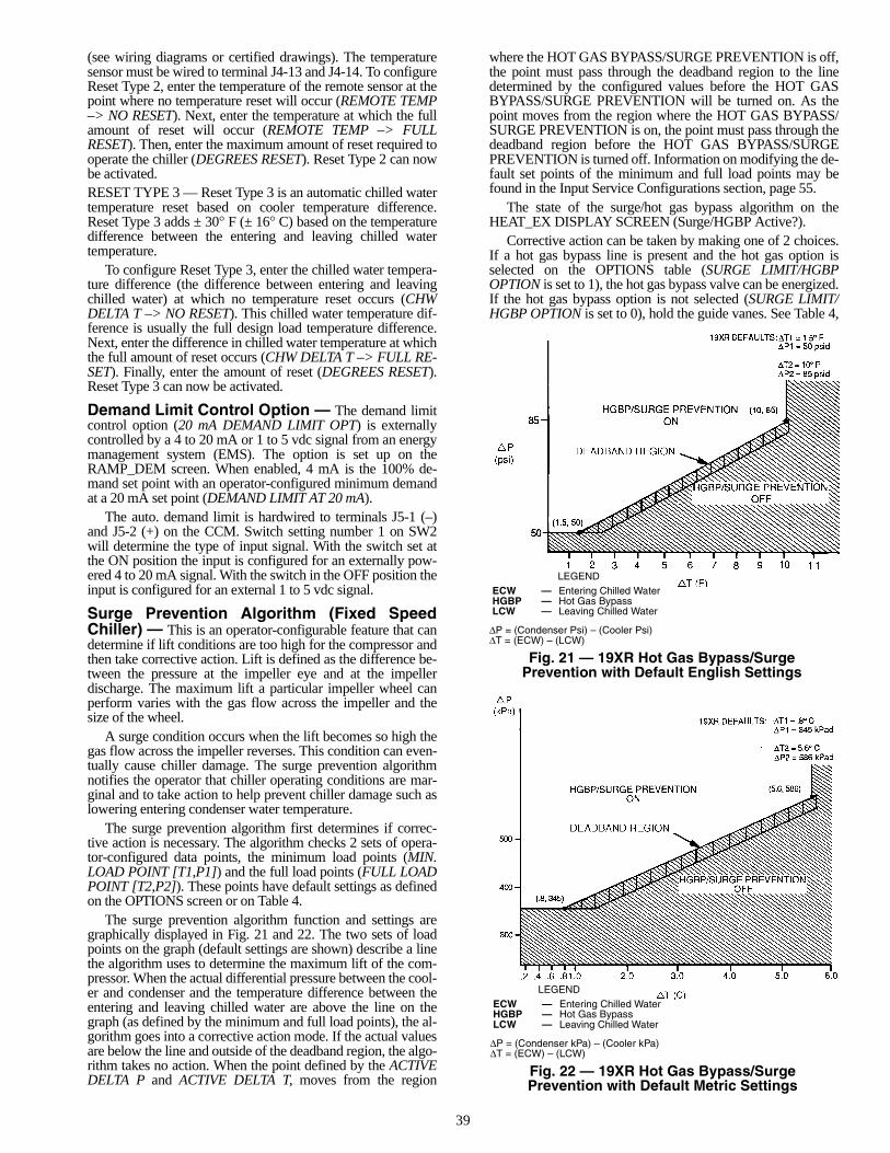
39
(see wiring diagrams or certified drawings). The temperaturesensor must be wired to terminal J4-13 and J4-14. To configureReset Type 2, enter the temperature of the remote sensor at thepoint where no temperature reset will occur (REMOTE TEMP–> NO RESET). Next, enter the temperature at which the fullamount of reset will occur (REMOTE TEMP –> FULLRESET). Then, enter the maximum amount of reset required tooperate the chiller (DEGREES RESET). Reset Type 2 can nowbe activated.RESET TYPE 3 — Reset Type 3 is an automatic chilled watertemperature reset based on cooler temperature difference.Reset Type 3 adds ± 30° F (± 16° C) based on the temperaturedifference between the entering and leaving chilled watertemperature.
To configure Reset Type 3, enter the chilled water tempera-ture difference (the difference between entering and leavingchilled water) at which no temperature reset occurs (CHWDELTA T –> NO RESET). This chilled water temperature dif-ference is usually the full design load temperature difference.Next, enter the difference in chilled water temperature at whichthe full amount of reset occurs (CHW DELTA T –> FULL RE-SET). Finally, enter the amount of reset (DEGREES RESET).Reset Type 3 can now be activated.
Demand Limit Control Option — The demand limitcontrol option (20 mA DEMAND LIMIT OPT) is externallycontrolled by a 4 to 20 mA or 1 to 5 vdc signal from an energymanagement system (EMS). The option is set up on theRAMP_DEM screen. When enabled, 4 mA is the 100% de-mand set point with an operator-configured minimum demandat a 20 mA set point (DEMAND LIMIT AT 20 mA).
The auto. demand limit is hardwired to terminals J5-1 (–)and J5-2 (+) on the CCM. Switch setting number 1 on SW2will determine the type of input signal. With the switch set atthe ON position the input is configured for an externally pow-ered 4 to 20 mA signal. With the switch in the OFF position theinput is configured for an external 1 to 5 vdc signal.
Surge Prevention Algorithm (Fixed SpeedChiller) — This is an operator-configurable feature that candetermine if lift conditions are too high for the compressor andthen take corrective action. Lift is defined as the difference be-tween the pressure at the impeller eye and at the impellerdischarge. The maximum lift a particular impeller wheel canperform varies with the gas flow across the impeller and thesize of the wheel.
A surge condition occurs when the lift becomes so high thegas flow across the impeller reverses. This condition can even-tually cause chiller damage. The surge prevention algorithmnotifies the operator that chiller operating conditions are mar-ginal and to take action to help prevent chiller damage such aslowering entering condenser water temperature.
The surge prevention algorithm first determines if correc-tive action is necessary. The algorithm checks 2 sets of opera-tor-configured data points, the minimum load points (MIN.LOAD POINT [T1,P1]) and the full load points (FULL LOADPOINT [T2,P2]). These points have default settings as definedon the OPTIONS screen or on Table 4.
The surge prevention algorithm function and settings aregraphically displayed in Fig. 21 and 22. The two sets of loadpoints on the graph (default settings are shown) describe a linethe algorithm uses to determine the maximum lift of the com-pressor. When the actual differential pressure between the cool-er and condenser and the temperature difference between theentering and leaving chilled water are above the line on thegraph (as defined by the minimum and full load points), the al-gorithm goes into a corrective action mode. If the actual valuesare below the line and outside of the deadband region, the algo-rithm takes no action. When the point defined by the ACTIVEDELTA P and ACTIVE DELTA T, moves from the region
where the HOT GAS BYPASS/SURGE PREVENTION is off,the point must pass through the deadband region to the linedetermined by the configured values before the HOT GASBYPASS/SURGE PREVENTION will be turned on. As thepoint moves from the region where the HOT GAS BYPASS/SURGE PREVENTION is on, the point must pass through thedeadband region before the HOT GAS BYPASS/SURGEPREVENTION is turned off. Information on modifying the de-fault set points of the minimum and full load points may befound in the Input Service Configurations section, page 55.
The state of the surge/hot gas bypass algorithm on theHEAT_EX DISPLAY SCREEN (Surge/HGBP Active?).
Corrective action can be taken by making one of 2 choices.If a hot gas bypass line is present and the hot gas option isselected on the OPTIONS table (SURGE LIMIT/HGBPOPTION is set to 1), the hot gas bypass valve can be energized.If the hot gas bypass option is not selected (SURGE LIMIT/HGBP OPTION is set to 0), hold the guide vanes. See Table 4,
LEGEND
∆P = (Condenser Psi) – (Cooler Psi)∆T = (ECW) – (LCW)
Fig. 21 — 19XR Hot Gas Bypass/SurgePrevention with Default English Settings
ECW — Entering Chilled WaterHGBP — Hot Gas BypassLCW — Leaving Chilled Water
LEGEND
∆P = (Condenser kPa) – (Cooler kPa)∆T = (ECW) – (LCW)
Fig. 22 — 19XR Hot Gas Bypass/SurgePrevention with Default Metric Settings
ECW — Entering Chilled WaterHGBP — Hot Gas BypassLCW — Leaving Chilled Water
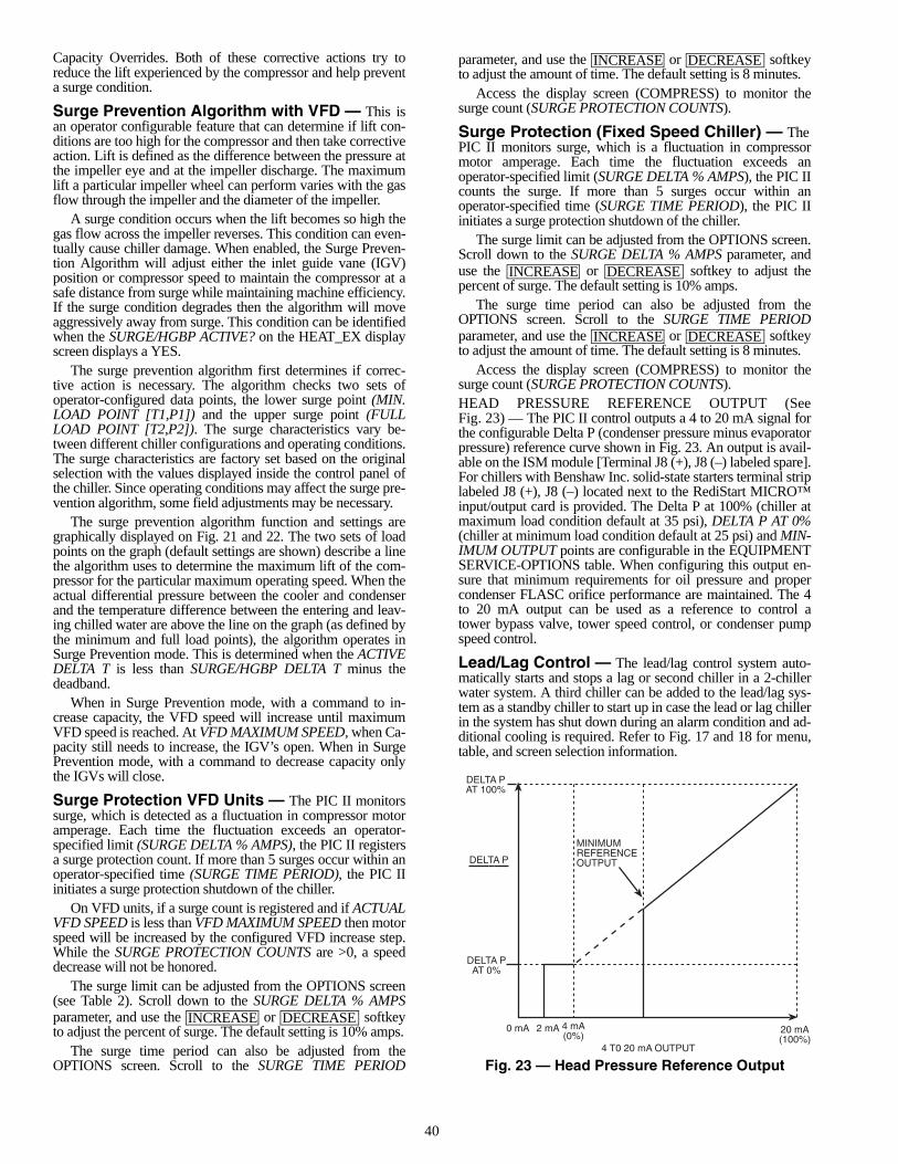
40
Capacity Overrides. Both of these corrective actions try toreduce the lift experienced by the compressor and help preventa surge condition.
Surge Prevention Algorithm with VFD — This isan operator configurable feature that can determine if lift con-ditions are too high for the compressor and then take correctiveaction. Lift is defined as the difference between the pressure atthe impeller eye and at the impeller discharge. The maximumlift a particular impeller wheel can perform varies with the gasflow through the impeller and the diameter of the impeller.
A surge condition occurs when the lift becomes so high thegas flow across the impeller reverses. This condition can even-tually cause chiller damage. When enabled, the Surge Preven-tion Algorithm will adjust either the inlet guide vane (IGV)position or compressor speed to maintain the compressor at asafe distance from surge while maintaining machine efficiency.If the surge condition degrades then the algorithm will moveaggressively away from surge. This condition can be identifiedwhen the SURGE/HGBP ACTIVE? on the HEAT_EX displayscreen displays a YES.
The surge prevention algorithm first determines if correc-tive action is necessary. The algorithm checks two sets ofoperator-configured data points, the lower surge point (MIN.LOAD POINT [T1,P1]) and the upper surge point (FULLLOAD POINT [T2,P2]). The surge characteristics vary be-tween different chiller configurations and operating conditions.The surge characteristics are factory set based on the originalselection with the values displayed inside the control panel ofthe chiller. Since operating conditions may affect the surge pre-vention algorithm, some field adjustments may be necessary.
The surge prevention algorithm function and settings aregraphically displayed on Fig. 21 and 22. The two sets of loadpoints on the graph (default settings are shown) describe a linethe algorithm uses to determine the maximum lift of the com-pressor for the particular maximum operating speed. When theactual differential pressure between the cooler and condenserand the temperature difference between the entering and leav-ing chilled water are above the line on the graph (as defined bythe minimum and full load points), the algorithm operates inSurge Prevention mode. This is determined when the ACTIVEDELTA T is less than SURGE/HGBP DELTA T minus thedeadband.
When in Surge Prevention mode, with a command to in-crease capacity, the VFD speed will increase until maximumVFD speed is reached. At VFD MAXIMUM SPEED, when Ca-pacity still needs to increase, the IGV’s open. When in SurgePrevention mode, with a command to decrease capacity onlythe IGVs will close.
Surge Protection VFD Units — The PIC II monitorssurge, which is detected as a fluctuation in compressor motoramperage. Each time the fluctuation exceeds an operator-specified limit (SURGE DELTA % AMPS), the PIC II registersa surge protection count. If more than 5 surges occur within anoperator-specified time (SURGE TIME PERIOD), the PIC IIinitiates a surge protection shutdown of the chiller.
On VFD units, if a surge count is registered and if ACTUALVFD SPEED is less than VFD MAXIMUM SPEED then motorspeed will be increased by the configured VFD increase step.While the SURGE PROTECTION COUNTS are >0, a speeddecrease will not be honored.
The surge limit can be adjusted from the OPTIONS screen(see Table 2). Scroll down to the SURGE DELTA % AMPSparameter, and use the or softkeyto adjust the percent of surge. The default setting is 10% amps.
The surge time period can also be adjusted from theOPTIONS screen. Scroll to the SURGE TIME PERIOD
parameter, and use the or softkeyto adjust the amount of time. The default setting is 8 minutes.
Access the display screen (COMPRESS) to monitor thesurge count (SURGE PROTECTION COUNTS).
Surge Protection (Fixed Speed Chiller) — ThePIC II monitors surge, which is a fluctuation in compressormotor amperage. Each time the fluctuation exceeds anoperator-specified limit (SURGE DELTA % AMPS), the PIC IIcounts the surge. If more than 5 surges occur within anoperator-specified time (SURGE TIME PERIOD), the PIC IIinitiates a surge protection shutdown of the chiller.
The surge limit can be adjusted from the OPTIONS screen.Scroll down to the SURGE DELTA % AMPS parameter, anduse the or softkey to adjust thepercent of surge. The default setting is 10% amps.
The surge time period can also be adjusted from theOPTIONS screen. Scroll to the SURGE TIME PERIODparameter, and use the or softkeyto adjust the amount of time. The default setting is 8 minutes.
Access the display screen (COMPRESS) to monitor thesurge count (SURGE PROTECTION COUNTS).HEAD PRESSURE REFERENCE OUTPUT (SeeFig. 23) — The PIC II control outputs a 4 to 20 mA signal forthe configurable Delta P (condenser pressure minus evaporatorpressure) reference curve shown in Fig. 23. An output is avail-able on the ISM module [Terminal J8 (+), J8 (–) labeled spare].For chillers with Benshaw Inc. solid-state starters terminal striplabeled J8 (+), J8 (–) located next to the RediStart MICRO™input/output card is provided. The Delta P at 100% (chiller atmaximum load condition default at 35 psi), DELTA P AT 0%(chiller at minimum load condition default at 25 psi) and MIN-IMUM OUTPUT points are configurable in the EQUIPMENTSERVICE-OPTIONS table. When configuring this output en-sure that minimum requirements for oil pressure and propercondenser FLASC orifice performance are maintained. The 4to 20 mA output can be used as a reference to control atower bypass valve, tower speed control, or condenser pumpspeed control.
Lead/Lag Control — The lead/lag control system auto-matically starts and stops a lag or second chiller in a 2-chillerwater system. A third chiller can be added to the lead/lag sys-tem as a standby chiller to start up in case the lead or lag chillerin the system has shut down during an alarm condition and ad-ditional cooling is required. Refer to Fig. 17 and 18 for menu,table, and screen selection information.
INCREASE DECREASE
INCREASE DECREASE
INCREASE DECREASE
INCREASE DECREASE
MINIMUMREFERENCEOUTPUT
DELTA PAT 100%
DELTA PAT 0%
DELTA P
0 mA 2 mA 4 mA(0%)
20 mA(100%)
4 T0 20 mA OUTPUT
Fig. 23 — Head Pressure Reference Output
41
NOTE: The lead/lag function can be configured on the LEAD-LAG screen, which is accessed from the SERVICE menu andEQUIPMENT SERVICE table. See Table 2, Example 20.Lead/lag status during chiller operation can be viewed on theLL_MAINT display screen, which is accessed from the SER-VICE menu and CONTROL ALGORITHM STATUS table.See Table 2, Example 12.Lead/Lag System Requirements:• all chillers in the system must have software capable of
performing the lead/lag function• water pumps MUST be energized from the PIC II
controls• water flows should be constant• the CCN time schedules for all chillers must be identical Operation Features:• 2 chiller lead/lag• addition of a third chiller for backup• manual rotation of lead chiller• load balancing if configured• staggered restart of the chillers after a power failure• chillers may be piped in parallel or in series chilled water
flowCOMMON POINT SENSOR INSTALLATION — Lead/lagoperation does not require a common chilled water point sen-sor. Common point sensors (Spare Temp #1 and #2) can beadded to the CCM module, if desired. Spare Temp #1 and #2are wired to plug J4 terminals 25-26 and 27-28 (J4 lower,respectively).NOTE: If the common point sensor option is chosen on achilled water system, each chiller should have its own commonpoint sensor installed. Each chiller uses its own common pointsensor for control when that chiller is designated as the leadchiller. The PIC II cannot read the value of common point sen-sors installed on the other chillers in the chilled water system.
If leaving chilled water control (ECW CONTROL OPTIONis set to 0 [DSABLE] TEMP_CTL screen) and a commonpoint sensor is desired (COMMON SENSOR OPTION inLEADLAG screen selected as 1) then the sensor is wired inSpare Temp #1 position on the CCM.
If the entering chilled water control option (ECW CON-TROL OPTION) is enabled (configured in TEMP_CTLscreen) and a common point sensor is desired (COMMONSENSOR OPTION in LEADLAG screen selected as 1) thenthe sensor is wired in Spare Temp #2 position on the CCM.
When installing chillers in series, a common point sensorshould be used. If a common point sensor is not used, the leav-ing chilled water sensor of the upstream chiller must be movedinto the leaving chilled water pipe of the downstream chiller.
If return chilled water control is required on chillers piped inseries, the common point return chilled water sensor should beinstalled. If this sensor is not installed, the return chilled watersensor of the downstream chiller must be relocated to the returnchilled water pipe of the upstream chiller.
To properly control the common supply point temperaturesensor when chillers are piped in parallel, the water flowthrough the shutdown chillers must be isolated so no water by-pass around the operating chiller occurs. The common pointsensor option must not be used if water bypass around the oper-ating chiller is occurring.CHILLER COMMUNICATION WIRING — Refer to thechiller’s Installation Instructions, Carrier Comfort NetworkInterface section for information on chiller communicationwiring.
LEAD/LAG OPERATION — The PIC II not only has theability to operate 2 chillers in lead/lag, but it can also start adesignated standby chiller when either the lead or lag chiller isfaulted and capacity requirements are not met. The lead/lag op-tion only operates when the chillers are in CCN mode. If anyother chiller configured for lead/lag is set to the LOCAL orOFF modes, it will be unavailable for lead/lag operation. Lead/Lag Chiller Configuration and Operation• A chiller is designated the lead chiller when its
LEADLAG: CONFIGURATION value on the LEAD-LAG screen is set to “1.”
• A chiller is designated the lag chiller when itsLEADLAG: CONFIGURATION value is set to “2.”
• A chiller is designated as a standby chiller when itsLEADLAG: CONFIGURATION value is set to “3.”
• A value of “0” disables the lead/lag designation of achiller.To configure the LAG ADDRESS value on the LEADLAG
screen, always enter the address of the other chiller on the sys-tem. For example, if you are configuring chiller A, enter the ad-dress for chiller B as the lag address. If you are configuringchiller B, enter the address for chiller A as the lag address. Thismakes it easier to rotate the lead and lag chillers.
If the address assignments in the LAG ADDRESS andSTANDBY ADDRESS parameters conflict, the lead/lag func-tion is disabled and an alert (!) message displays. For example,if the LAG ADDRESS matches the lead chiller’s address, thelead/lag will be disabled and an alert (!) message displayed.The lead/lag maintenance screen (LL_MAINT) displays themessage ‘INVALID CONFIG’ in the LEADLAG: CONFIGU-RATION and CURRENT MODE fields.
The lead chiller responds to normal start/stop controls suchas the occupancy schedule, a forced start or stop, and remotestart contact inputs. After completing start-up and ramp load-ing, the PIC II evaluates the need for additional capacity. If ad-ditional capacity is needed, the PIC II initiates the start-up ofthe chiller configured at the LAG ADDRESS. If the lag chilleris faulted (in alarm) or is in the OFF or LOCAL modes, thechiller at the STANDBY ADDRESS (if configured) is requestedto start. After the second chiller is started and is running, thelead chiller monitors conditions and evaluates whether the ca-pacity has been reduced enough for the lead chiller to sustainthe system alone. If the capacity is reduced enough for the leadchiller to sustain the CONTROL POINT temperatures alone,then the operating lag chiller is stopped.
If the lead chiller is stopped in CCN mode for any reasonother than an alarm (*) condition, the lag and standby chillersare also stopped. If the configured lead chiller stops for analarm condition, the configured lag chiller takes the lead chill-er’s place as the lead chiller, and the standby chiller serves asthe lag chiller.
If the configured lead chiller does not complete the start-upbefore the PRESTART FAULT TIMER (a user-configuredvalue) elapses, then the lag chiller starts and the lead chillershuts down. The lead chiller then monitors the start requestfrom the acting lead chiller. The PRESTART FAULT TIMER isinitiated at the time of a start request. The PRESTART FAULTTIMER provides a timeout if there is a prestart alert conditionthat prevents the chiller from starting in a timely manner. ThePRESTART FAULT TIMER parameter is on the LEADLAGscreen, which is accessed from the EQUIPMENT SERVICEtable of the SERVICE menu.
If the lag chiller does not achieve start-up before the PRE-START FAULT TIMER elapses, the lag chiller stops, and thestandby chiller is requested to start, if configured and ready.
42
Standby Chiller Configuration and Operation — A chiller isdesignated as a standby chiller when its LEADLAG: CONFIG-URATION value on the LEADLAG screen is set to “3.” Thestandby chiller can operate as a replacement for the lag chilleronly if one of the other two chillers is in an alarm (*) condition(as shown on the CVC/ICVC panel). If both lead and lag chill-ers are in an alarm (*) condition, the standby chiller defaults tooperate in CCN mode, based on its configured occupancyschedule and remote contacts input.Lag Chiller Start-Up Requirements — Before the lag chillercan be started, the following conditions must be met:
1. Lead chiller ramp loading must be complete.2. Lead chilled water temperature must be greater than the
CONTROL POINT temperature (see the MAINSTATscreen) plus 1/2 the CHILLED WATER DEADBANDtemperature (see the SETUP1 screen).NOTE: The chilled water temperature sensor may be theleaving chilled water sensor, the return water sensor, thecommon supply water sensor, or the common return wa-ter sensor, depending on which options are configuredand enabled.
3. Lead chiller ACTIVE DEMAND LIMIT (see the MAIN-STAT screen) value must be greater than 95% of full loadamps.
4. Lead chiller temperature pulldown rate (TEMP PULL-DOWN DEG/MIN on the TEMP_CTL screen) of thechilled water temperature is less than 0.5° F (0.27° C) perminute.
5. The lag chiller status indicates it is in CCN mode and isnot in an alarm condition. If the current lag chiller is in analarm condition, the standby chiller becomes the activelag chiller, if it is configured and available.
6. The configured LAG START TIMER entry has elapsed.The LAG START TIMER starts when the lead chiller ramploading is completed. The LAG START TIMER entry ison the LEADLAG screen, which is accessed from theEQUIPMENT SERVICE table of the SERVICE menu.
When all the above requirements have been met, the lagchiller is commanded to a STARTUP mode (SUPVSR flashingnext to the point value on the STATUS table). The PIC II con-trol then monitors the lag chiller for a successful start. If the lagchiller fails to start, the standby chiller, if configured, is started.Lag Chiller Shutdown Requirements — The following condi-tions must be met in order for the lag chiller to be stopped.
1. Lead chiller compressor motor average line current orload value (MOTOR PERCENT KILOWATTS on theMAINSTAT screen) is less than the lead chiller percentcapacity.NOTE: Lead chiller percent capacity = 115 – LAG % CA-PACITY. The LAG % CAPACITY parameter is on theLEADLAG screen, which is accessed from the EQUIP-MENT SERVICE table on the SERVICE menu.
2. The lead chiller chilled water temperature is less than theCONTROL POINT temperature (see the MAINSTATscreen) plus 1/2 the CHILLED WATER DEADBAND tem-perature (see the SETUP1 screen).
3. The configured LAG STOP TIMER entry has elapsed.The LAG STOP TIMER starts when the lead chillerchilled water temperature is less than the chilled waterCONTROL POINT plus 1/2 of the CHILLED WATERDEADBAND and the lead chiller compressor motor load(MOTOR PERCENT KILOWATT or AVERAGE LINECURRENT on the MAINSTAT screen) is less than thelead chiller percent capacity.
NOTE: Lead chiller percent capacity = 115 – LAG % CAPAC-ITY. The LAG % CAPACITY parameter is on the LEADLAGscreen, which is accessed from the EQUIPMENT SERVICEtable on the SERVICE menu.FAULTED CHILLER OPERATION — If the lead chillershuts down because of an alarm (*) condition, it stops commu-nicating to the lag and standby chillers. After 30 seconds, thelag chiller becomes the acting lead chiller and starts and stopsthe standby chiller, if necessary.
If the lag chiller goes into alarm when the lead chiller is alsoin alarm, the standby chiller reverts to a stand-alone CCNmode of operation.
If the lead chiller is in an alarm (*) condition (as shown onthe CVC/ICVC panel), press the softkey to clear thealarm. The chiller is placed in CCN mode. The lead chillercommunicates and monitors the RUN STATUS of the lag andstandby chillers. If both the lag and standby chillers are run-ning, the lead chiller does not attempt to start and does not as-sume the role of lead chiller until either the lag or standby chill-er shuts down. If only one chiller is running, the lead chillerwaits for a start request from the operating chiller. When theconfigured lead chiller starts, it assumes its role as lead chiller.
If the lag chiller is the only chiller running when the leadchiller assumes its role as a lead chiller then the lag chiller willperform a RECOVERY START REQUEST (LL_MAINTscreen). The lead chiller will start up when the following condi-tions are met.
1. Lag chiller ramp loading must be complete.2. Lag CHILLED WATER TEMP (MAINSTAT screen) is
greater than CONTROL POINT plus 1/2 the CHILLEDWATER DEADBAND temperature.
3. Lag chiller ACTIVE DEMAND LIMIT value must begreater than 95% of full load amps.
4. Lag chiller temperature pulldown rate (TEMP PULL-DOWN DEG/MIN) of the chilled water temperature isless than 0.5 F (0.27 C) per minute.
5. The standby chiller is not running as a lag chiller.6. The configured LAG START TIMER has elapsed. The
LAG START TIMER is started when ramp loading iscompleted.
LOAD BALANCING — When the LOAD BALANCEOPTION (see LEADLAG screen) is enabled, the lead chillersets the ACTIVE DEMAND LIMIT in the lag chiller to the leadchiller’s compressor motor load value MOTOR PERCENTKILOWATTS or AVERAGE LINE CURRENT on the MAIN-STAT screen). This value has limits of 40% to 100%. When thelag chiller ACTIVE DEMAND LIMIT is set, the CONTROLPOINT must be modified to a value of 3° F (1.67° C) less thanthe lead chiller’s CONTROL POINT value. If the LOAD BAL-ANCE OPTION is disabled, the ACTIVE DEMAND LIMITand the CONTROL POINT are forced to the same value as thelead chiller.AUTO. RESTART AFTER POWER FAILURE — When anauto. restart condition occurs, each chiller may have a delayadded to the start-up sequence, depending on its lead/lag con-figuration. The lead chiller does not have a delay. The lag chill-er has a 45-second delay. The standby chiller has a 90-seconddelay. The delay time is added after the chiller water flow isverified. The PIC II ensures the guide vanes are closed. Afterthe guide vane position is confirmed, the delay for lag andstandby chillers occurs prior to energizing the oil pump. Thenormal start-up sequence then continues. The auto. restart de-lay sequence occurs whether the chiller is in CCN or LOCALmode and is intended to stagger the compressor motor starts.Preventing the motors from starting simultaneously helps re-duce the inrush demands on the building power system.
RESET
43
Ice Build Control — The ice build control option auto-matically sets the CONTROL POINT of the chiller to a temper-ature that allows ice building for thermal storage.NOTE: For ice build control to operate properly, the PIC IImust be in CCN mode.NOTE: See Fig. 17 and 18 for more information on ice build-related menus.
The PIC II can be configured for ice build operation.• From the SERVICE menu, access the EQUIPMENT
SERVICE table. From there, select the OPTIONS screento enable or disable the ICE BUILD OPTION. SeeTable 2, Example 17.
• The ICE BUILD SETPOINT can be configured from theSETPOINT display, which is accessed from the PIC IImain menu. See Table 2, Example 9.
• The ice build schedule can be viewed or modified fromthe SCHEDULE table. From this table, select the icebuild schedule (OCCPC02S) screen. See Fig. 19 and thesection on Time Schedule Operation, page 20, for moreinformation on modifying chiller schedules.The ice build time schedule defines the period(s) during
which ice build is active if the ice build option is enabled. If theice build time schedule overlaps other schedules, the ice buildtime schedule takes priority. During the ice build period, theCONTROL POINT is set to the ICE BUILD SETPOINT fortemperature control. The ICE BUILD RECYCLE and ICEBUILD TERMINATION parameters, accessed from theOPTIONS screen, allow the chiller operator to recycle or ter-minate the ice build cycle. The ice build cycle can be config-ured to terminate if:• the ENTERING CHILLED WATER temperature is less
than the ICE BUILD SETPOINT. In this case, the opera-tor sets the ICE BUILD TERMINATION parameter to 0on the OPTIONS screen.
• the REMOTE CONTACT inputs from an ice level indi-cator are opened. In this case, the operator sets the ICEBUILD TERMINATION parameter to 1 on the OPTIONSscreen.
• the chilled water temperature is less than the ice build setpoint and the remote contact inputs from an ice levelindicator are open. In this case, the operator sets the ICEBUILD TERMINATION parameter to 2 on the OPTIONSscreen.
• the end of the ice build time schedule has been reached.ICE BUILD INITIATION — The ice build time schedule(OCCPC02S) is the means for activating the ice build option.The ice build option is enabled if:• a day of the week and a time period on the ice build time
schedule are enabled. The SCHEDULE screen shows anX in the day field and ON/OFF times are designated forthe day(s),
• and the ICE BUILD OPTION is enabled.The following events take place (unless overridden by a
higher authority CCN device).• CHILLER START/STOP is forced to START.• The CONTROL POINT is forced to the ICE BUILD SET-
POINT.• Any force (Auto) is removed from the ACTIVE
DEMAND LIMIT.NOTE: A parameter’s value can be forced, that is, the valuecan be manually changed at the CVC/ICVC by an operator,changed from another CCN device, or changed by other algo-rithms in the PIC II control system.NOTE: The Ice Build steps do not occur if the chiller is config-ured and operating as a lag or standby chiller for lead/lag oper-ation and is actively being controlled by a lead chiller. The leadchiller communicates the ICE BUILD SET POINT, the desiredCHILLER START/STOP state, and the ACTIVE DEMAND
LIMIT to the lag or standby chiller as required for ice build, ifconfigured to do so.START-UP/RECYCLE OPERATION — If the chiller is notrunning when ice build activates, the PIC II checks the follow-ing conditions, based on the ICE BUILD TERMINATIONvalue, to avoid starting the compressor unnecessarily:• if ICE BUILD TERMINATION is set to the TEMP option
and the ENTERING CHILLED WATER temperature isless than or equal to the ICE BUILD SETPOINT;
• if ICE BUILD TERMINATION is set to the CONTACTSoption and the remote contacts are open;
• if the ICE BUILD TERMINATION is set to the BOTH(temperature and contacts) option and the ENTERINGCHILLED WATER temperature is less than or equal tothe ICE BUILD SETPOINT and the remote contacts areopen.The ICE BUILD RECYCLE on the OPTIONS screen deter-
mines whether or not the chiller will go into an ice build RE-CYCLE mode.• If the ICE BUILD RECYCLE is set to DSABLE (dis-
able), the PIC II reverts to normal temperature controlwhen the ice build function terminates.
• If the ICE BUILD RECYCLE is set to ENABLE, the PICII goes into an ICE BUILD RECYCLE mode and thechilled water pump relay remains energized to keep thechilled water flowing when the ice build function termi-nates. If the temperature of the ENTERING CHILLEDWATER increases above the ICE BUILD SETPOINT plusthe RECYCLE RESTART DELTA T value, the compres-sor restarts and controls the chilled water/brine tempera-ture to the ICE BUILD SETPOINT.
TEMPERATURE CONTROL DURING ICE BUILD —During ice build, the capacity control algorithm shall use theCONTROL POINT minus 5 F (–2.8 C) for control of theLEAVING CHILLED WATER temperature. (See Table 2, ex-ample 10, the CAPACITY CONTROL parameter on the CA-PACITY screen.) The ECW CONTROL OPTION and any tem-perature reset option shall be ignored, if enabled, during icebuild. The AUTO DEMAND LIMIT INPUT shall also beignored if enabled during ice build.• ECW CONTROL OPTION and any temperature reset
options (configured on TEMP_CTL screen).• 20 mA DEMAND LIMIT OPT (configured on
RAMP_DEM screen).TERMINATION OF ICE BUILD — The ice build functionterminates under the following conditions:
1. Time Schedule — When the current time on the ice buildtime schedule (OCCPC02S) is not set as an ice build timeperiod.
2. Entering Chilled Water Temperature — Compressoroperation terminates, based on temperature, if the ICEBUILD TERMINATION parameter is set to 0 (TEMP),the ENTERING CHILLED WATER temperature is lessthan the ICE BUILD SETPOINT, and the ICE BUILDRECYCLE is set to DSABLE. If the ICE BUILD RECY-CLE OPTION is set to ENABLE, a recycle shutdown oc-curs and recycle start-up depends on the LEAVINGCHILLED WATER temperature being greater than thewater/brine CONTROL POINT plus the RESTARTDELTA T temperature.
3. Remote Contacts/Ice Level Input — Compressor opera-tion terminates when the ICE BUILD TERMINATIONparameter is set to 1 (CONTACTS) and the remote con-tacts are open and the ICE BUILD RECYCLE is set toDSABLE (0). In this case, the contacts provide ice leveltermination control. The contacts are used to stop the icebuild function when a time period on the ice build sched-ule (OCCPC02S) is set for ice build operation. The re-mote contacts can still be opened and closed to start and
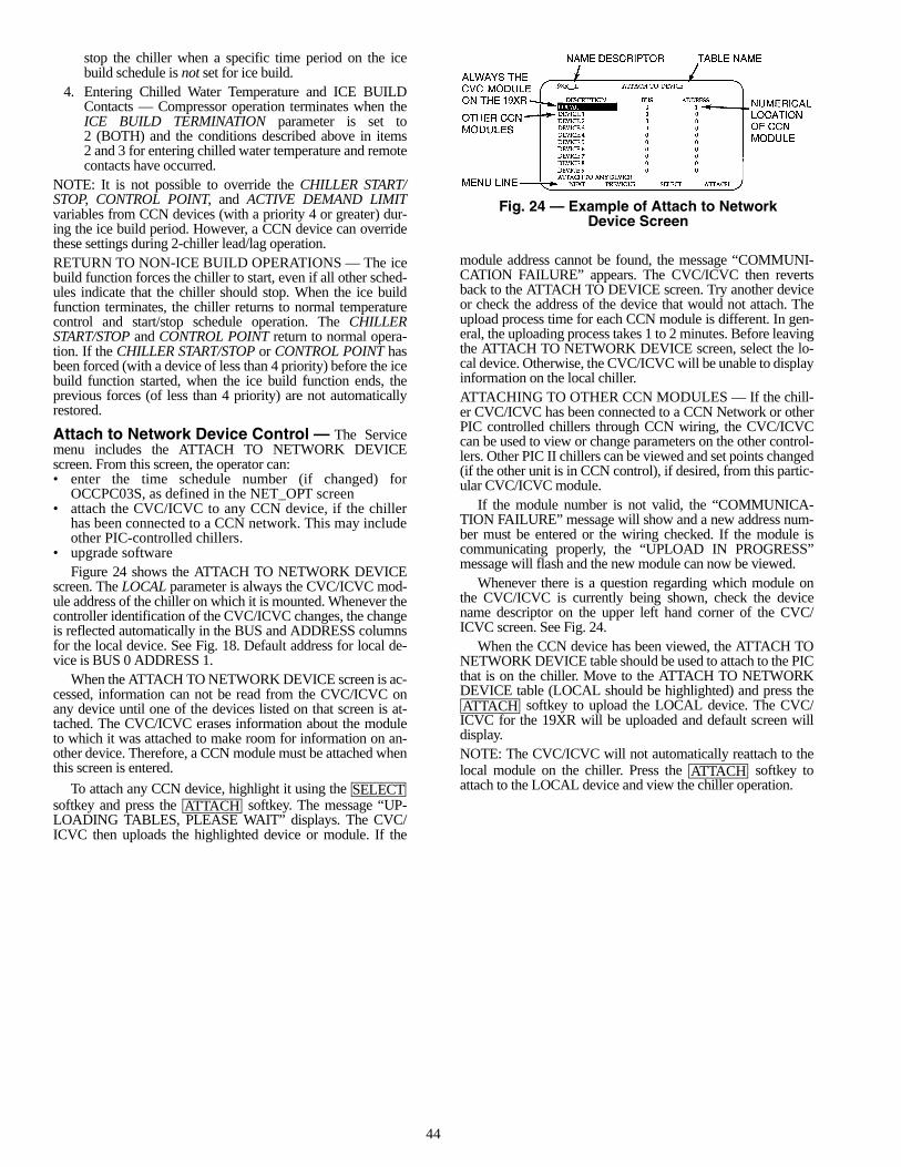
44
stop the chiller when a specific time period on the icebuild schedule is not set for ice build.
4. Entering Chilled Water Temperature and ICE BUILDContacts — Compressor operation terminates when theICE BUILD TERMINATION parameter is set to2 (BOTH) and the conditions described above in items2 and 3 for entering chilled water temperature and remotecontacts have occurred.
NOTE: It is not possible to override the CHILLER START/STOP, CONTROL POINT, and ACTIVE DEMAND LIMITvariables from CCN devices (with a priority 4 or greater) dur-ing the ice build period. However, a CCN device can overridethese settings during 2-chiller lead/lag operation.RETURN TO NON-ICE BUILD OPERATIONS — The icebuild function forces the chiller to start, even if all other sched-ules indicate that the chiller should stop. When the ice buildfunction terminates, the chiller returns to normal temperaturecontrol and start/stop schedule operation. The CHILLERSTART/STOP and CONTROL POINT return to normal opera-tion. If the CHILLER START/STOP or CONTROL POINT hasbeen forced (with a device of less than 4 priority) before the icebuild function started, when the ice build function ends, theprevious forces (of less than 4 priority) are not automaticallyrestored.
Attach to Network Device Control — The Servicemenu includes the ATTACH TO NETWORK DEVICEscreen. From this screen, the operator can: • enter the time schedule number (if changed) for
OCCPC03S, as defined in the NET_OPT screen• attach the CVC/ICVC to any CCN device, if the chiller
has been connected to a CCN network. This may includeother PIC-controlled chillers.
• upgrade softwareFigure 24 shows the ATTACH TO NETWORK DEVICE
screen. The LOCAL parameter is always the CVC/ICVC mod-ule address of the chiller on which it is mounted. Whenever thecontroller identification of the CVC/ICVC changes, the changeis reflected automatically in the BUS and ADDRESS columnsfor the local device. See Fig. 18. Default address for local de-vice is BUS 0 ADDRESS 1.
When the ATTACH TO NETWORK DEVICE screen is ac-cessed, information can not be read from the CVC/ICVC onany device until one of the devices listed on that screen is at-tached. The CVC/ICVC erases information about the moduleto which it was attached to make room for information on an-other device. Therefore, a CCN module must be attached whenthis screen is entered.
To attach any CCN device, highlight it using the softkey and press the softkey. The message “UP-LOADING TABLES, PLEASE WAIT” displays. The CVC/ICVC then uploads the highlighted device or module. If the
module address cannot be found, the message “COMMUNI-CATION FAILURE” appears. The CVC/ICVC then revertsback to the ATTACH TO DEVICE screen. Try another deviceor check the address of the device that would not attach. Theupload process time for each CCN module is different. In gen-eral, the uploading process takes 1 to 2 minutes. Before leavingthe ATTACH TO NETWORK DEVICE screen, select the lo-cal device. Otherwise, the CVC/ICVC will be unable to displayinformation on the local chiller.ATTACHING TO OTHER CCN MODULES — If the chill-er CVC/ICVC has been connected to a CCN Network or otherPIC controlled chillers through CCN wiring, the CVC/ICVCcan be used to view or change parameters on the other control-lers. Other PIC II chillers can be viewed and set points changed(if the other unit is in CCN control), if desired, from this partic-ular CVC/ICVC module.
If the module number is not valid, the “COMMUNICA-TION FAILURE” message will show and a new address num-ber must be entered or the wiring checked. If the module iscommunicating properly, the “UPLOAD IN PROGRESS”message will flash and the new module can now be viewed.
Whenever there is a question regarding which module onthe CVC/ICVC is currently being shown, check the devicename descriptor on the upper left hand corner of the CVC/ICVC screen. See Fig. 24.
When the CCN device has been viewed, the ATTACH TONETWORK DEVICE table should be used to attach to the PICthat is on the chiller. Move to the ATTACH TO NETWORKDEVICE table (LOCAL should be highlighted) and press the
softkey to upload the LOCAL device. The CVC/ICVC for the 19XR will be uploaded and default screen willdisplay.NOTE: The CVC/ICVC will not automatically reattach to thelocal module on the chiller. Press the softkey toattach to the LOCAL device and view the chiller operation.SELECT
ATTACH
ATTACH
ATTACH
Fig. 24 — Example of Attach to NetworkDevice Screen
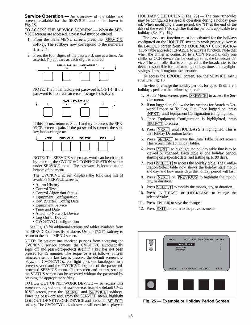
45
Service Operation — An overview of the tables andscreens available for the SERVICE function is shown inFig. 18.TO ACCESS THE SERVICE SCREENS — When the SER-VICE screens are accessed, a password must be entered.
1. From the main MENU screen, press the softkey. The softkeys now correspond to the numerals1, 2, 3, 4.
2. Press the four digits of the password, one at a time. Anasterisk (*) appears as each digit is entered
NOTE: The initial factory-set password is 1-1-1-1. If thepassword is incorrect, an error message is displayed
If this occurs, return to Step 1 and try to access the SER-VICE screens again. If the password is correct, the soft-key labels change to:
NOTE: The SERVICE screen password can be changedby entering the CVC/ICVC CONFIGURATION screenunder SERVICE menu. The password is located at thebottom of the menu.The CVC/ICVC screen displays the following list ofavailable SERVICE screens:• Alarm History• Control Test• Control Algorithm Status• Equipment Configuration• ISM (Starter) Config Data• Equipment Service• Time and Date• Attach to Network Device• Log Out of Device• CVC/ICVC Configuration
See Fig. 18 for additional screens and tables available fromthe SERVICE screens listed above. Use the softkey toreturn to the main MENU screen.NOTE: To prevent unauthorized persons from accessing theCVC/ICVC service screens, the CVC/ICVC automaticallysigns off and password-protects itself if a key has not beenpressed for 15 minutes. The sequence is as follows. Fifteenminutes after the last key is pressed, the default screen dis-plays, the CVC/ICVC screen light goes out (analogous to ascreen saver), and the CVC/ICVC logs out of the password-protected SERVICE menu. Other screen and menus, such asthe STATUS screen can be accessed without the password bypressing the appropriate softkey.TO LOG OUT OF NETWORK DEVICE — To access thisscreen and log out of a network device, from the default CVC/ICVC screen, press the and softkeys.Enter the password and, from the SERVICE menu, highlightLOG OUT OF NETWORK DEVICE and press the softkey. The CVC/ICVC default screen will now be displayed.
HOLIDAY SCHEDULING (Fig. 25) — The time schedulesmay be configured for special operation during a holiday peri-od. When modifying a time period, the “H” at the end of thedays of the week field signifies that the period is applicable to aholiday. (See Fig. 19.)
The broadcast function must be activated for the holidaysconfigured on the HOLIDEF screen to work properly. Accessthe BRODEF screen from the EQUIPMENT CONFIGURA-TION table and select ENABLE to activate function. Note thatwhen the chiller is connected to a CCN Network, only onechiller or CCN device can be configured as the broadcast de-vice. The controller that is configured as the broadcaster is thedevice responsible for transmitting holiday, time, and daylight-savings dates throughout the network.
To access the BRODEF screen, see the SERVICE menustructure, Fig. 18.
To view or change the holiday periods for up to 18 differentholidays, perform the following operation:
1. At the Menu screen, press to access the Ser-vice menu.
2. If not logged on, follow the instructions for Attach to Net-work Device or To Log Out. Once logged on, press
until Equipment Configuration is highlighted.3. Once Equipment Configuration is highlighted, press
to access.
4. Press until HOLIDAYS is highlighted. This isthe Holiday Definition table.
5. Press to enter the Data Table Select screen.This screen lists 18 holiday tables.
6. Press to highlight the holiday table that is to beviewed or changed. Each table is one holiday period,starting on a specific date, and lasting up to 99 days.
7. Press to access the holiday table. The Config-uration Select table now shows the holiday start monthand day, and how many days the holiday period will last.
8. Press or to highlight the month,day, or duration.
9. Press to modify the month, day, or duration.
10. Press or to change theselected value.
11. Press to save the changes.
12. Press to return to the previous menu.
SERVICE
EXIT
MENU SERVICE
SELECT
SERVICE
NEXT
SELECT
NEXT
SELECT
NEXT
SELECT
NEXT PREVIOUS
SELECT
INCREASE DECREASE
ENTER
EXIT
Fig. 25 — Example of Holiday Period Screen
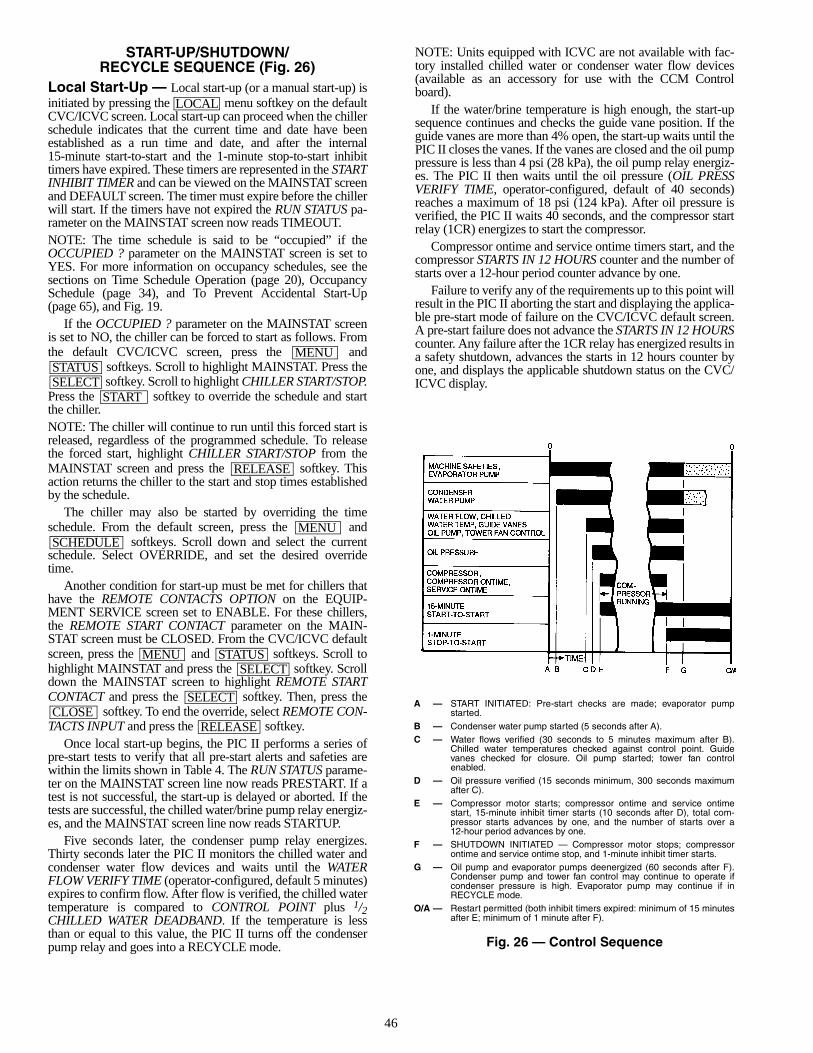
46
START-UP/SHUTDOWN/RECYCLE SEQUENCE (Fig. 26)
Local Start-Up — Local start-up (or a manual start-up) isinitiated by pressing the menu softkey on the defaultCVC/ICVC screen. Local start-up can proceed when the chillerschedule indicates that the current time and date have beenestablished as a run time and date, and after the internal15-minute start-to-start and the 1-minute stop-to-start inhibittimers have expired. These timers are represented in the STARTINHIBIT TIMER and can be viewed on the MAINSTAT screenand DEFAULT screen. The timer must expire before the chillerwill start. If the timers have not expired the RUN STATUS pa-rameter on the MAINSTAT screen now reads TIMEOUT.NOTE: The time schedule is said to be “occupied” if theOCCUPIED ? parameter on the MAINSTAT screen is set toYES. For more information on occupancy schedules, see thesections on Time Schedule Operation (page 20), OccupancySchedule (page 34), and To Prevent Accidental Start-Up(page 65), and Fig. 19.
If the OCCUPIED ? parameter on the MAINSTAT screenis set to NO, the chiller can be forced to start as follows. Fromthe default CVC/ICVC screen, press the and
softkeys. Scroll to highlight MAINSTAT. Press the softkey. Scroll to highlight CHILLER START/STOP.
Press the softkey to override the schedule and startthe chiller.NOTE: The chiller will continue to run until this forced start isreleased, regardless of the programmed schedule. To releasethe forced start, highlight CHILLER START/STOP from theMAINSTAT screen and press the softkey. Thisaction returns the chiller to the start and stop times establishedby the schedule.
The chiller may also be started by overriding the timeschedule. From the default screen, press the and
softkeys. Scroll down and select the currentschedule. Select OVERRIDE, and set the desired overridetime.
Another condition for start-up must be met for chillers thathave the REMOTE CONTACTS OPTION on the EQUIP-MENT SERVICE screen set to ENABLE. For these chillers,the REMOTE START CONTACT parameter on the MAIN-STAT screen must be CLOSED. From the CVC/ICVC defaultscreen, press the and softkeys. Scroll tohighlight MAINSTAT and press the softkey. Scrolldown the MAINSTAT screen to highlight REMOTE STARTCONTACT and press the softkey. Then, press the
softkey. To end the override, select REMOTE CON-TACTS INPUT and press the softkey.
Once local start-up begins, the PIC II performs a series ofpre-start tests to verify that all pre-start alerts and safeties arewithin the limits shown in Table 4. The RUN STATUS parame-ter on the MAINSTAT screen line now reads PRESTART. If atest is not successful, the start-up is delayed or aborted. If thetests are successful, the chilled water/brine pump relay energiz-es, and the MAINSTAT screen line now reads STARTUP.
Five seconds later, the condenser pump relay energizes.Thirty seconds later the PIC II monitors the chilled water andcondenser water flow devices and waits until the WATERFLOW VERIFY TIME (operator-configured, default 5 minutes)expires to confirm flow. After flow is verified, the chilled watertemperature is compared to CONTROL POINT plus 1/2CHILLED WATER DEADBAND. If the temperature is lessthan or equal to this value, the PIC II turns off the condenserpump relay and goes into a RECYCLE mode.
NOTE: Units equipped with ICVC are not available with fac-tory installed chilled water or condenser water flow devices(available as an accessory for use with the CCM Controlboard).
If the water/brine temperature is high enough, the start-upsequence continues and checks the guide vane position. If theguide vanes are more than 4% open, the start-up waits until thePIC II closes the vanes. If the vanes are closed and the oil pumppressure is less than 4 psi (28 kPa), the oil pump relay energiz-es. The PIC II then waits until the oil pressure (OIL PRESSVERIFY TIME, operator-configured, default of 40 seconds)reaches a maximum of 18 psi (124 kPa). After oil pressure isverified, the PIC II waits 40 seconds, and the compressor startrelay (1CR) energizes to start the compressor.
Compressor ontime and service ontime timers start, and thecompressor STARTS IN 12 HOURS counter and the number ofstarts over a 12-hour period counter advance by one.
Failure to verify any of the requirements up to this point willresult in the PIC II aborting the start and displaying the applica-ble pre-start mode of failure on the CVC/ICVC default screen.A pre-start failure does not advance the STARTS IN 12 HOURScounter. Any failure after the 1CR relay has energized results ina safety shutdown, advances the starts in 12 hours counter byone, and displays the applicable shutdown status on the CVC/ICVC display.
LOCAL
MENUSTATUSSELECT
START
RELEASE
MENUSCHEDULE
MENU STATUSSELECT
SELECTCLOSE
RELEASE
A — START INITIATED: Pre-start checks are made; evaporator pumpstarted.
B — Condenser water pump started (5 seconds after A).C — Water flows verified (30 seconds to 5 minutes maximum after B).
Chilled water temperatures checked against control point. Guidevanes checked for closure. Oil pump started; tower fan controlenabled.
D — Oil pressure verified (15 seconds minimum, 300 seconds maximumafter C).
E — Compressor motor starts; compressor ontime and service ontimestart, 15-minute inhibit timer starts (10 seconds after D), total com-pressor starts advances by one, and the number of starts over a12-hour period advances by one.
F — SHUTDOWN INITIATED — Compressor motor stops; compressorontime and service ontime stop, and 1-minute inhibit timer starts.
G — Oil pump and evaporator pumps deenergized (60 seconds after F).Condenser pump and tower fan control may continue to operate ifcondenser pressure is high. Evaporator pump may continue if inRECYCLE mode.
O/A — Restart permitted (both inhibit timers expired: minimum of 15 minutesafter E; minimum of 1 minute after F).
Fig. 26 — Control Sequence
47
Shutdown Sequence — Chiller shutdown begins ifany of the following occurs:• the STOP button is pressed for at least one second (the
alarm light blinks once to confirm the stop command)• a recycle condition is present (see Chilled Water Recycle
Mode section)• the time schedule has gone into unoccupied mode• the chiller protective limit has been reached and chiller is
in alarm• the start/stop status is overridden to stop from the CCN
network or the CVC/ICVCWhen a stop signal occurs, the shutdown sequence first
stops the compressor by deactivating the start relay (1CR). Astatus message of “SHUTDOWN IN PROGRESS, COM-PRESSOR DEENERGIZED” is displayed, and the compres-sor ontime and service ontime stop. The guide vanes are thenbrought to the closed position. The oil pump relay and thechilled water/brine pump relay shut down 60 seconds after thecompressor stops. The condenser water pump shuts down atthe same time if the ENTERING CONDENSER WATER tem-perature is greater than or equal to 115 F (46.1 C) and theCONDENSER REFRIG TEMP is greater than the CONDENS-ER FREEZE POINT plus 5 F (–15.0 C). The stop-to-start timernow begins to count down. If the start-to-start timer value isstill greater than the value of the start-to-stop timer, then thistime displays on the CVC/ICVC.
Certain conditions that occur during shutdown can changethis sequence.• If the AVERAGE LINE CURRENT is greater than 5%
after shutdown, or the starter contacts remain energized,the oil pump and chilled water pump remain energizedand the alarm is displayed.
• The condenser pump shuts down when the CON-DENSER PRESSURE is less than the COND PRESSOVERRIDE threshold minus 3.5 psi (24.1 kPa) and theCONDENSER REFRIG TEMP is less than or equal to theENTERING CONDENSER WATER temperature plus3° F (–1.6° C).
• If the chiller shuts down due to low refrigerant tempera-ture, the chilled water pump continues to run until theLEAVING CHILLED WATER temperature is greater thanthe CONTROL POINT temperature, plus 5° F (3° C).
Automatic Soft Stop Amps Threshold — The softstop amps threshold feature closes the guide vanes of the com-pressor automatically if a non-recycle, non-alarm stop signaloccurs before the compressor motor is deenergized.
If the STOP button is pressed, the guide vanes close to apreset amperage percent until the guide vane is less than 4%open or 4 minutes have passed. The compressor then shuts off.
If the chiller enters an alarm state or if the compressor entersa RECYCLE mode, the compressor deenergizes immediately.
To activate the soft stop amps threshold feature, scroll to thebottom of OPTIONS screen on the CVC/ICVC. Use the
or softkey to set the SOFT STOPAMPS THRESHOLD parameter to the percent of amps atwhich the motor will shut down. The default setting is 100%amps (no soft stop). The range is 40 to 100%.
When the soft stop amps threshold feature is being applied,a status message, “SHUTDOWN IN PROGRESS, COM-PRESSOR UNLOADING” displays on the CVC/ICVC.
The soft stop amps threshold function can be terminated andthe compressor motor deenergized immediately by depressingthe STOP button twice.
Chilled Water Recycle Mode — The chiller maycycle off and wait until the load increases to restart when thecompressor is running in a lightly loaded condition. This cy-cling is normal and is known as “recycle.” A recycle shutdownis initiated when any of the following conditions are true:• the chiller is in LCW control, the difference between the
LEAVING CHILLED WATER temperature and ENTER-ING CHILLED WATER temperature is less than theRECYCLE SHUTDOWN DELTA T (found in theSETUP1 table) the LEAVING CHILLED WATER tem-perature is 5° F (2.8° C) below the CONTROL POINT,the CONTROL POINT has not increased in the last5 minutes and ICE BUILD is not active.
• the ECW CONTROL OPTION is enabled, the differencebetween the ENTERING CHILLED WATER temperatureand the LEAVING CHILLED WATER temperature is lessthan the RECYCLE SHUTDOWN DELTA T (found in theSETUP1 table), the ENTERING CHILLED WATER tem-perature is 5° F (2.8° C) below the CONTROL POINT,and the CONTROL POINT has not increased in the last5 minutes.
• the LEAVING CHILLED WATER temperature is within3° F (2° C) of the EVAP REFRIG TRIPPOINT.When the chiller is in RECYCLE mode, the chilled water
pump relay remains energized so the chilled water temperaturecan be monitored for increasing load. The recycle control usesRESTART DELTA T to check when the compressor should berestarted. This is an operator-configured function which de-faults to 5° F (3° C). This value can be viewed or modified onthe SETUP1 table. The compressor will restart when the chilleris:• in LCW CONTROL and the LEAVING CHILLED
WATER temperature is greater than the CONTROLPOINT plus the RECYCLE RESTART DELTA T.
• in ECW CONTROL and the ENTERING CHILLEDWATER temperature is greater than the CONTROLPOINT plus the RECYCLE RESTART DELTA T.Once these conditions are met, the compressor initiates a
start-up with a normal start-up sequence.An alert condition may be generated if 5 or more recycle
start-ups occur in less than 4 hours. Excessive recycling canreduce chiller life; therefore, compressor recycling due to ex-tremely low loads should be reduced.
To reduce compressor recycling, use the time schedule toshut the chiller down during known low load operation period,or increase the chiller load by running the fan systems. If thehot gas bypass is installed, adjust the values to ensure that hotgas is energized during light load conditions. Increase theRECYCLE RESTART DELTA T on the SETUP1 table tolengthen the time between restarts.
The chiller should not be operated below design minimumload without a hot gas bypass installed.
Safety Shutdown — A safety shutdown is identical toa manual shutdown with the exception that, during a safetyshutdown, the CVC/ICVC displays the reason for the shut-down, the alarm light blinks continuously, and the spare alarmcontacts are energized.
After a safety shutdown, the softkey must bepressed to clear the alarm. If the alarm condition is still present,the alarm light continues to blink. Once the alarm is cleared,the operator must press the or softkeys to re-start the chiller.
INCREASE DECREASE
RESET
CCN LOCAL
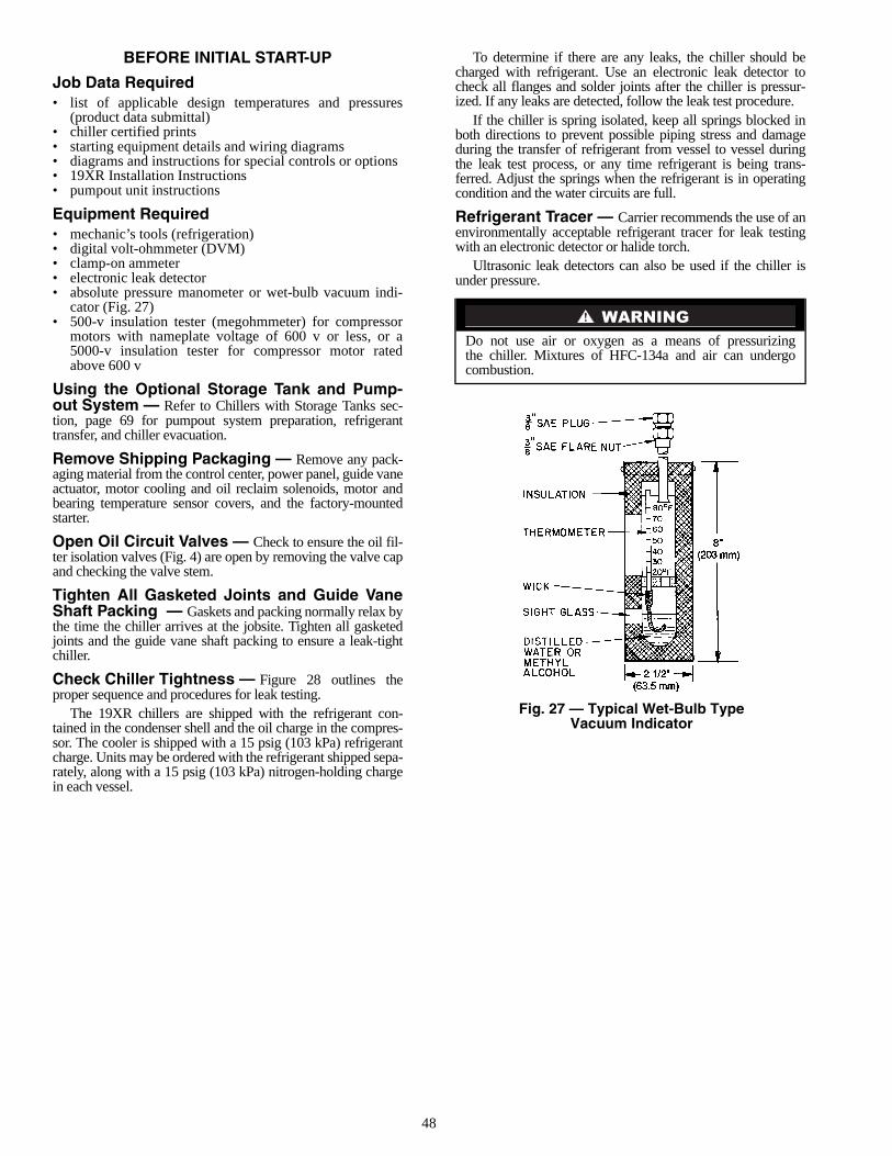
48
BEFORE INITIAL START-UP
Job Data Required• list of applicable design temperatures and pressures
(product data submittal)• chiller certified prints• starting equipment details and wiring diagrams• diagrams and instructions for special controls or options• 19XR Installation Instructions• pumpout unit instructions
Equipment Required• mechanic’s tools (refrigeration)• digital volt-ohmmeter (DVM)• clamp-on ammeter• electronic leak detector• absolute pressure manometer or wet-bulb vacuum indi-
cator (Fig. 27)• 500-v insulation tester (megohmmeter) for compressor
motors with nameplate voltage of 600 v or less, or a5000-v insulation tester for compressor motor ratedabove 600 v
Using the Optional Storage Tank and Pump-out System — Refer to Chillers with Storage Tanks sec-tion, page 69 for pumpout system preparation, refrigeranttransfer, and chiller evacuation.
Remove Shipping Packaging — Remove any pack-aging material from the control center, power panel, guide vaneactuator, motor cooling and oil reclaim solenoids, motor andbearing temperature sensor covers, and the factory-mountedstarter.
Open Oil Circuit Valves — Check to ensure the oil fil-ter isolation valves (Fig. 4) are open by removing the valve capand checking the valve stem.
Tighten All Gasketed Joints and Guide VaneShaft Packing — Gaskets and packing normally relax bythe time the chiller arrives at the jobsite. Tighten all gasketedjoints and the guide vane shaft packing to ensure a leak-tightchiller.
Check Chiller Tightness — Figure 28 outlines theproper sequence and procedures for leak testing.
The 19XR chillers are shipped with the refrigerant con-tained in the condenser shell and the oil charge in the compres-sor. The cooler is shipped with a 15 psig (103 kPa) refrigerantcharge. Units may be ordered with the refrigerant shipped sepa-rately, along with a 15 psig (103 kPa) nitrogen-holding chargein each vessel.
To determine if there are any leaks, the chiller should becharged with refrigerant. Use an electronic leak detector tocheck all flanges and solder joints after the chiller is pressur-ized. If any leaks are detected, follow the leak test procedure.
If the chiller is spring isolated, keep all springs blocked inboth directions to prevent possible piping stress and damageduring the transfer of refrigerant from vessel to vessel duringthe leak test process, or any time refrigerant is being trans-ferred. Adjust the springs when the refrigerant is in operatingcondition and the water circuits are full.
Refrigerant Tracer — Carrier recommends the use of anenvironmentally acceptable refrigerant tracer for leak testingwith an electronic detector or halide torch.
Ultrasonic leak detectors can also be used if the chiller isunder pressure.
Do not use air or oxygen as a means of pressurizingthe chiller. Mixtures of HFC-134a and air can undergocombustion.
Fig. 27 — Typical Wet-Bulb TypeVacuum Indicator
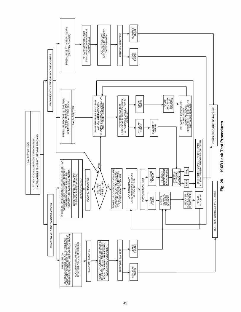
49
Fig
. 28
— 1
9XR
Lea
k T
est
Pro
ced
ure
s
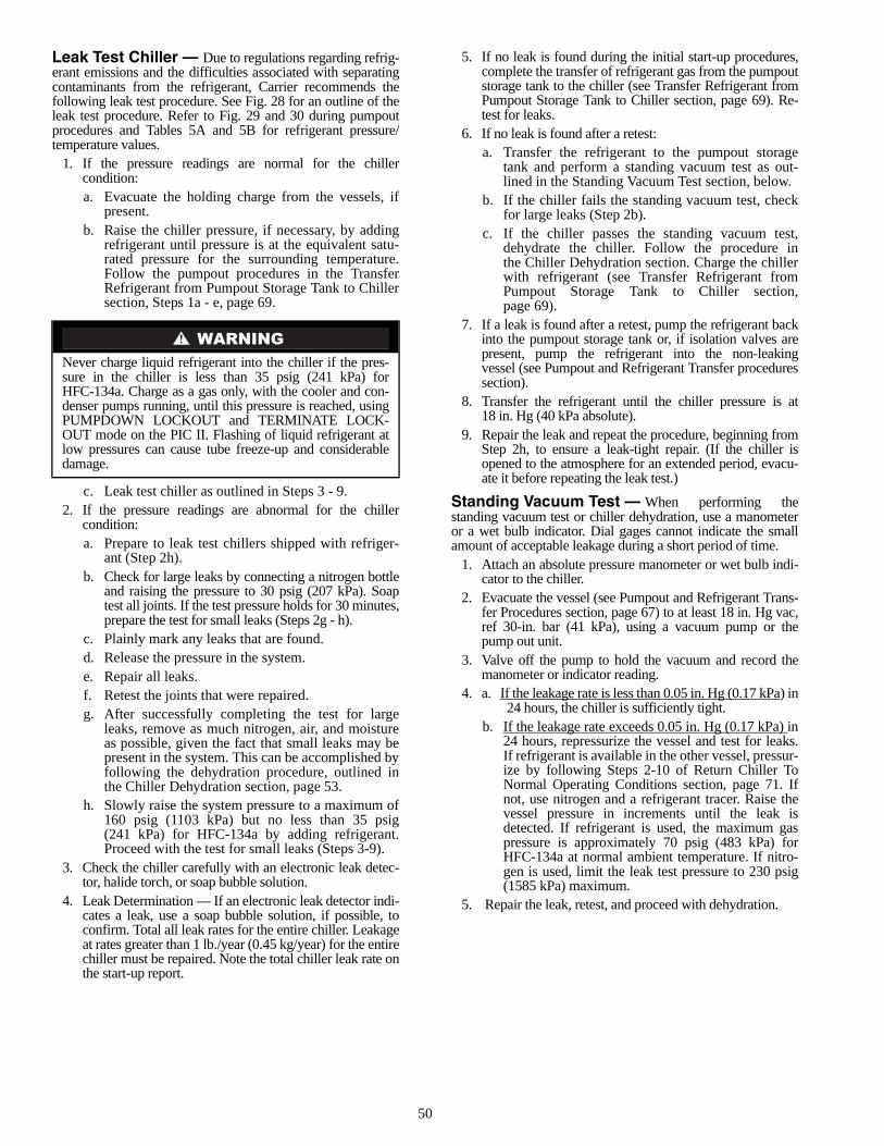
50
Leak Test Chiller — Due to regulations regarding refrig-erant emissions and the difficulties associated with separatingcontaminants from the refrigerant, Carrier recommends thefollowing leak test procedure. See Fig. 28 for an outline of theleak test procedure. Refer to Fig. 29 and 30 during pumpoutprocedures and Tables 5A and 5B for refrigerant pressure/temperature values.
1. If the pressure readings are normal for the chillercondition:a. Evacuate the holding charge from the vessels, if
present.b. Raise the chiller pressure, if necessary, by adding
refrigerant until pressure is at the equivalent satu-rated pressure for the surrounding temperature.Follow the pumpout procedures in the TransferRefrigerant from Pumpout Storage Tank to Chillersection, Steps 1a - e, page 69.
c. Leak test chiller as outlined in Steps 3 - 9.2. If the pressure readings are abnormal for the chiller
condition:a. Prepare to leak test chillers shipped with refriger-
ant (Step 2h).b. Check for large leaks by connecting a nitrogen bottle
and raising the pressure to 30 psig (207 kPa). Soaptest all joints. If the test pressure holds for 30 minutes,prepare the test for small leaks (Steps 2g - h).
c. Plainly mark any leaks that are found.d. Release the pressure in the system.e. Repair all leaks.f. Retest the joints that were repaired.g. After successfully completing the test for large
leaks, remove as much nitrogen, air, and moistureas possible, given the fact that small leaks may bepresent in the system. This can be accomplished byfollowing the dehydration procedure, outlined inthe Chiller Dehydration section, page 53.
h. Slowly raise the system pressure to a maximum of160 psig (1103 kPa) but no less than 35 psig(241 kPa) for HFC-134a by adding refrigerant.Proceed with the test for small leaks (Steps 3-9).
3. Check the chiller carefully with an electronic leak detec-tor, halide torch, or soap bubble solution.
4. Leak Determination — If an electronic leak detector indi-cates a leak, use a soap bubble solution, if possible, toconfirm. Total all leak rates for the entire chiller. Leakageat rates greater than 1 lb./year (0.45 kg/year) for the entirechiller must be repaired. Note the total chiller leak rate onthe start-up report.
5. If no leak is found during the initial start-up procedures,complete the transfer of refrigerant gas from the pumpoutstorage tank to the chiller (see Transfer Refrigerant fromPumpout Storage Tank to Chiller section, page 69). Re-test for leaks.
6. If no leak is found after a retest:a. Transfer the refrigerant to the pumpout storage
tank and perform a standing vacuum test as out-lined in the Standing Vacuum Test section, below.
b. If the chiller fails the standing vacuum test, checkfor large leaks (Step 2b).
c. If the chiller passes the standing vacuum test,dehydrate the chiller. Follow the procedure inthe Chiller Dehydration section. Charge the chillerwith refrigerant (see Transfer Refrigerant fromPumpout Storage Tank to Chiller section,page 69).
7. If a leak is found after a retest, pump the refrigerant backinto the pumpout storage tank or, if isolation valves arepresent, pump the refrigerant into the non-leakingvessel (see Pumpout and Refrigerant Transfer proceduressection).
8. Transfer the refrigerant until the chiller pressure is at18 in. Hg (40 kPa absolute).
9. Repair the leak and repeat the procedure, beginning fromStep 2h, to ensure a leak-tight repair. (If the chiller isopened to the atmosphere for an extended period, evacu-ate it before repeating the leak test.)
Standing Vacuum Test — When performing thestanding vacuum test or chiller dehydration, use a manometeror a wet bulb indicator. Dial gages cannot indicate the smallamount of acceptable leakage during a short period of time.
1. Attach an absolute pressure manometer or wet bulb indi-cator to the chiller.
2. Evacuate the vessel (see Pumpout and Refrigerant Trans-fer Procedures section, page 67) to at least 18 in. Hg vac,ref 30-in. bar (41 kPa), using a vacuum pump or thepump out unit.
3. Valve off the pump to hold the vacuum and record themanometer or indicator reading.
4. a. If the leakage rate is less than 0.05 in. Hg (0.17 kPa) in24 hours, the chiller is sufficiently tight.
b. If the leakage rate exceeds 0.05 in. Hg (0.17 kPa) in24 hours, repressurize the vessel and test for leaks.If refrigerant is available in the other vessel, pressur-ize by following Steps 2-10 of Return Chiller ToNormal Operating Conditions section, page 71. Ifnot, use nitrogen and a refrigerant tracer. Raise thevessel pressure in increments until the leak isdetected. If refrigerant is used, the maximum gaspressure is approximately 70 psig (483 kPa) forHFC-134a at normal ambient temperature. If nitro-gen is used, limit the leak test pressure to 230 psig(1585 kPa) maximum.
5. Repair the leak, retest, and proceed with dehydration.
Never charge liquid refrigerant into the chiller if the pres-sure in the chiller is less than 35 psig (241 kPa) forHFC-134a. Charge as a gas only, with the cooler and con-denser pumps running, until this pressure is reached, usingPUMPDOWN LOCKOUT and TERMINATE LOCK-OUT mode on the PIC II. Flashing of liquid refrigerant atlow pressures can cause tube freeze-up and considerabledamage.
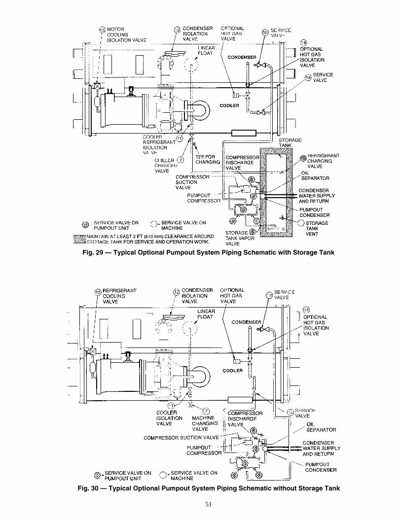
51
Fig. 29 — Typical Optional Pumpout System Piping Schematic with Storage Tank
Fig. 30 — Typical Optional Pumpout System Piping Schematic without Storage Tank
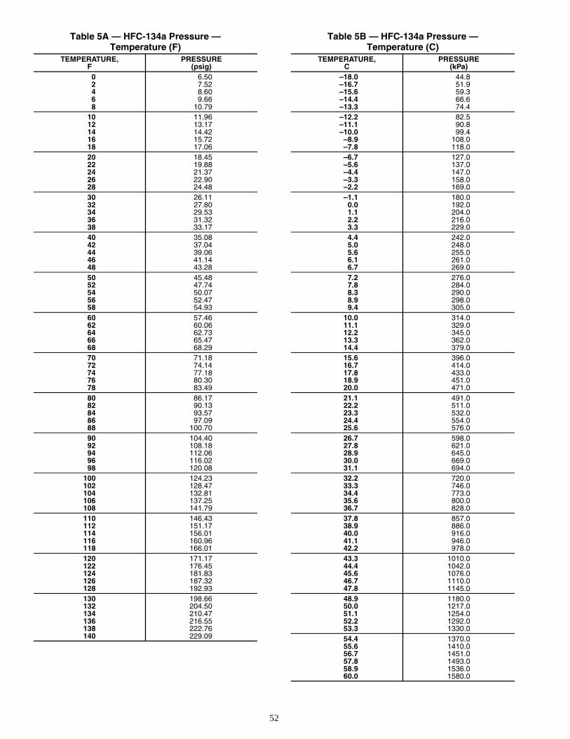
52
Table 5A — HFC-134a Pressure —Temperature (F)
Table 5B — HFC-134a Pressure —Temperature (C)
TEMPERATURE,F
PRESSURE(psig)
0 6.502 7.524 8.606 9.668 10.79
10 11.9612 13.1714 14.4216 15.7218 17.0620 18.4522 19.8824 21.3726 22.9028 24.4830 26.1132 27.8034 29.5336 31.3238 33.1740 35.0842 37.0444 39.0646 41.1448 43.2850 45.4852 47.7454 50.0756 52.4758 54.9360 57.4662 60.0664 62.7366 65.4768 68.2970 71.1872 74.1474 77.1876 80.3078 83.4980 86.1782 90.1384 93.5786 97.0988 100.7090 104.4092 108.1894 112.0696 116.0298 120.08
100 124.23102 128.47104 132.81106 137.25108 141.79110 146.43112 151.17114 156.01116 160.96118 166.01120 171.17122 176.45124 181.83126 187.32128 192.93130 198.66132 204.50134 210.47136 216.55138 222.76140 229.09
TEMPERATURE,C
PRESSURE(kPa)
–18.0 44.8–16.7 51.9–15.6 59.3–14.4 66.6–13.3 74.4–12.2 82.5–11.1 90.8–10.0 99.4
–8.9 108.0–7.8 118.0–6.7 127.0–5.6 137.0–4.4 147.0–3.3 158.0–2.2 169.0–1.1 180.0
0.0 192.01.1 204.02.2 216.03.3 229.04.4 242.05.0 248.05.6 255.06.1 261.06.7 269.07.2 276.07.8 284.08.3 290.08.9 298.09.4 305.0
10.0 314.011.1 329.012.2 345.013.3 362.014.4 379.015.6 396.016.7 414.017.8 433.018.9 451.020.0 471.021.1 491.022.2 511.023.3 532.024.4 554.025.6 576.026.7 598.027.8 621.028.9 645.030.0 669.031.1 694.032.2 720.033.3 746.034.4 773.035.6 800.036.7 828.037.8 857.038.9 886.040.0 916.041.1 946.042.2 978.043.3 1010.044.4 1042.045.6 1076.046.7 1110.047.8 1145.048.9 1180.050.0 1217.051.1 1254.052.2 1292.053.3 1330.054.4 1370.055.6 1410.056.7 1451.057.8 1493.058.9 1536.060.0 1580.0
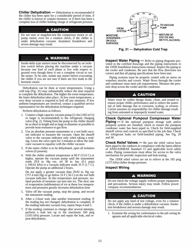
53
Chiller Dehydration — Dehydration is recommended ifthe chiller has been open for a considerable period of time, ifthe chiller is known to contain moisture, or if there has been acomplete loss of chiller holding charge or refrigerant pressure.
Dehydration can be done at room temperatures. Using acold trap (Fig. 31) may substantially reduce the time requiredto complete the dehydration. The higher the room temperature,the faster dehydration takes place. At low room temperatures, avery deep vacuum is required to boil off any moisture. If lowambient temperatures are involved, contact a qualified servicerepresentative for the dehydration techniques required.
Perform dehydration as follows:1. Connect a high capacity vacuum pump (5 cfm [.002 m3/s]
or larger is recommended) to the refrigerant chargingvalve (Fig. 2). Tubing from the pump to the chiller shouldbe as short in length and as large in diameter as possible toprovide least resistance to gas flow.
2. Use an absolute pressure manometer or a wet bulb vacu-um indicator to measure the vacuum. Open the shutoffvalve to the vacuum indicator only when taking a read-ing. Leave the valve open for 3 minutes to allow the indi-cator vacuum to equalize with the chiller vacuum.
3. If the entire chiller is to be dehydrated, open all isolationvalves (if present).
4. With the chiller ambient temperature at 60 F (15.6 C) orhigher, operate the vacuum pump until the manometerreads 29.8 in. Hg vac, ref 30 in. bar. (0.1 psia)(–100.61 kPa) or a vacuum indicator reads 35 F (1.7 C).Operate the pump an additional 2 hours.Do not apply a greater vacuum than 29.82 in. Hg vac(757.4 mm Hg) or go below 33 F (.56 C) on the wet bulbvacuum indicator. At this temperature and pressure, iso-lated pockets of moisture can turn into ice. The slow rateof evaporation (sublimation) of ice at these low tempera-tures and pressures greatly increases dehydration time.
5. Valve off the vacuum pump, stop the pump, and recordthe instrument reading.
6. After a 2-hour wait, take another instrument reading. Ifthe reading has not changed, dehydration is complete. Ifthe reading indicates vacuum loss, repeat Steps 4 and 5.
7. If the reading continues to change after several attempts,perform a leak test up to the maximum 160 psig(1103 kPa) pressure. Locate and repair the leak, and re-peat dehydration.
Inspect Water Piping — Refer to piping diagrams pro-vided in the certified drawings and the piping instructions inthe 19XR Installation Instructions manual. Inspect the piping tothe cooler and condenser. Be sure that the flow directions arecorrect and that all piping specifications have been met.
Piping systems must be properly vented with no stress onwaterbox nozzles and covers. Water flows through the coolerand condenser must meet job requirements. Measure the pres-sure drop across the cooler and the condenser.
Check Optional Pumpout Compressor WaterPiping — If the optional pumpout storage tank and/orpumpout system are installed, check to ensure the pumpoutcondenser water has been piped in. Check for field-suppliedshutoff valves and controls as specified in the job data. Checkfor refrigerant leaks on field-installed piping. See Fig. 29and 30.
Check Relief Valves — Be sure the relief valves havebeen piped to the outdoors in compliance with the latest editionof ANSI/ASHRAE Standard 15 and applicable local safetycodes. Piping connections must allow for access to the valvemechanism for periodic inspection and leak testing.
The 19XR relief valves are set to relieve at the 185 psig(1275 kPa) chiller design pressure.
Inspect Wiring
1. Examine the wiring for conformance to the job wiring di-agrams and all applicable electrical codes.
Do not start or megohm-test the compressor motor or oilpump motor, even for a rotation check, if the chiller isunder dehydration vacuum. Insulation breakdown andsevere damage may result.
Inside-delta type starters must be disconnected by an isola-tion switch before placing the machine under a vacuumbecause one lead of each phase is live with respect toground even though there is not a complete circuit to runthe motor. To be safe, isolate any starter before evacuatingthe chiller if you are not sure if there are live leads to thehermetic motor.
Water must be within design limits, clean, and treated toensure proper chiller performance and to reduce the poten-tial of tube damage due to corrosion, scaling, or erosion.Carrier assumes no responsibility for chiller damage result-ing from untreated or improperly treated water.
Do not check the voltage supply without proper equipmentand precautions. Serious injury may result. Follow powercompany recommendations.
Do not apply any kind of test voltage, even for a rotationcheck, if the chiller is under a dehydration vacuum. Insula-tion breakdown and serious damage may result.
Fig. 31 — Dehydration Cold Trap
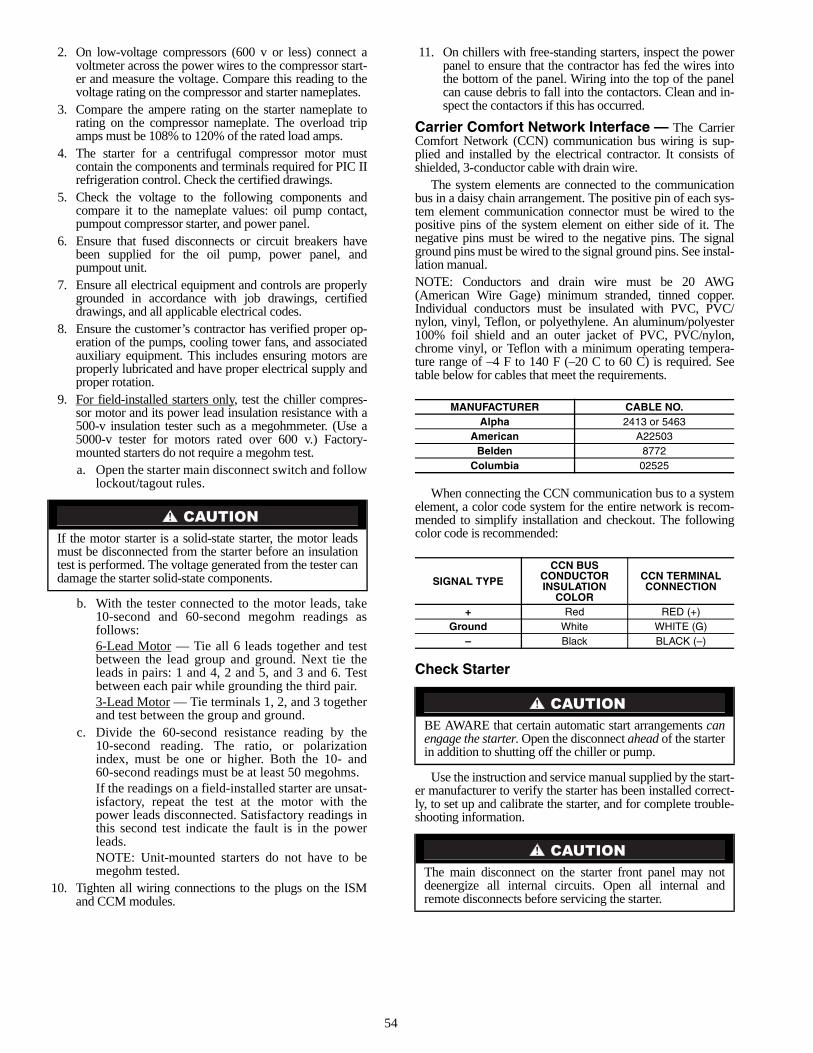
54
2. On low-voltage compressors (600 v or less) connect avoltmeter across the power wires to the compressor start-er and measure the voltage. Compare this reading to thevoltage rating on the compressor and starter nameplates.
3. Compare the ampere rating on the starter nameplate torating on the compressor nameplate. The overload tripamps must be 108% to 120% of the rated load amps.
4. The starter for a centrifugal compressor motor mustcontain the components and terminals required for PIC IIrefrigeration control. Check the certified drawings.
5. Check the voltage to the following components andcompare it to the nameplate values: oil pump contact,pumpout compressor starter, and power panel.
6. Ensure that fused disconnects or circuit breakers havebeen supplied for the oil pump, power panel, andpumpout unit.
7. Ensure all electrical equipment and controls are properlygrounded in accordance with job drawings, certifieddrawings, and all applicable electrical codes.
8. Ensure the customer’s contractor has verified proper op-eration of the pumps, cooling tower fans, and associatedauxiliary equipment. This includes ensuring motors areproperly lubricated and have proper electrical supply andproper rotation.
9. For field-installed starters only, test the chiller compres-sor motor and its power lead insulation resistance with a500-v insulation tester such as a megohmmeter. (Use a5000-v tester for motors rated over 600 v.) Factory-mounted starters do not require a megohm test.a. Open the starter main disconnect switch and follow
lockout/tagout rules.
b. With the tester connected to the motor leads, take10-second and 60-second megohm readings asfollows:6-Lead Motor — Tie all 6 leads together and testbetween the lead group and ground. Next tie theleads in pairs: 1 and 4, 2 and 5, and 3 and 6. Testbetween each pair while grounding the third pair.3-Lead Motor — Tie terminals 1, 2, and 3 togetherand test between the group and ground.
c. Divide the 60-second resistance reading by the10-second reading. The ratio, or polarizationindex, must be one or higher. Both the 10- and60-second readings must be at least 50 megohms.If the readings on a field-installed starter are unsat-isfactory, repeat the test at the motor with thepower leads disconnected. Satisfactory readings inthis second test indicate the fault is in the powerleads.NOTE: Unit-mounted starters do not have to bemegohm tested.
10. Tighten all wiring connections to the plugs on the ISMand CCM modules.
11. On chillers with free-standing starters, inspect the powerpanel to ensure that the contractor has fed the wires intothe bottom of the panel. Wiring into the top of the panelcan cause debris to fall into the contactors. Clean and in-spect the contactors if this has occurred.
Carrier Comfort Network Interface — The CarrierComfort Network (CCN) communication bus wiring is sup-plied and installed by the electrical contractor. It consists ofshielded, 3-conductor cable with drain wire.
The system elements are connected to the communicationbus in a daisy chain arrangement. The positive pin of each sys-tem element communication connector must be wired to thepositive pins of the system element on either side of it. Thenegative pins must be wired to the negative pins. The signalground pins must be wired to the signal ground pins. See instal-lation manual.NOTE: Conductors and drain wire must be 20 AWG(American Wire Gage) minimum stranded, tinned copper.Individual conductors must be insulated with PVC, PVC/nylon, vinyl, Teflon, or polyethylene. An aluminum/polyester100% foil shield and an outer jacket of PVC, PVC/nylon,chrome vinyl, or Teflon with a minimum operating tempera-ture range of –4 F to 140 F (–20 C to 60 C) is required. Seetable below for cables that meet the requirements.
When connecting the CCN communication bus to a systemelement, a color code system for the entire network is recom-mended to simplify installation and checkout. The followingcolor code is recommended:
Check Starter
Use the instruction and service manual supplied by the start-er manufacturer to verify the starter has been installed correct-ly, to set up and calibrate the starter, and for complete trouble-shooting information.
If the motor starter is a solid-state starter, the motor leadsmust be disconnected from the starter before an insulationtest is performed. The voltage generated from the tester candamage the starter solid-state components.
MANUFACTURER CABLE NO.Alpha 2413 or 5463
American A22503Belden 8772
Columbia 02525
SIGNAL TYPE
CCN BUS CONDUCTORINSULATION
COLOR
CCN TERMINALCONNECTION
+ Red RED (+)Ground White WHITE (G)
– Black BLACK (–)
BE AWARE that certain automatic start arrangements canengage the starter. Open the disconnect ahead of the starterin addition to shutting off the chiller or pump.
The main disconnect on the starter front panel may notdeenergize all internal circuits. Open all internal andremote disconnects before servicing the starter.
55
MECHANICAL STARTER1. Check all field wiring connections for tightness, clear-
ance from moving parts, and correct connection.2. Check the contactor(s) to ensure they move freely. Check
the mechanical interlock between contactors to ensurethat 1S and 2M contactors cannot be closed at the sametime. Check all other electro-mechanical devices, such asrelays, for free movement. If the devices do not movefreely, contact the starter manufacturer for replacementcomponents.
3. Reapply starter control power (not main chiller power) tocheck the electrical functions.Ensure the starter (with relay 1CR closed) goes through acomplete and proper start cycle.
BENSHAW, INC. RediStart MICRO™ SOLID-STATESTARTER
1. Ensure all wiring connections are properly terminated tothe starter.
2. Verify the ground wire to the starter is installed properlyand is sufficient size.
3. Verify the motors are properly grounded to the starter.4. Verify the proper ac input voltage is brought into the start-
er according to the certified drawings.5. Apply power to the starter
VFD STARTER1. Turn off unit, tag and lock disconnects and wait 5 minutes.2. Verify that the DC voltage is zero. 3. Ensure there is adequate clearance around the drive. 4. Verify that the wiring to the terminal strip and power ter-
minals is correct.5. Verify that wire size is within the terminal specification
and the wires are secure.6. Inspect the field supplied branch circuit protection is
properly rated and installed.7. Verify that the system is properly grounded.8. Inspect all liquid cooling connections for leaks.
Oil Charge — The oil charge for the 19XR compressor de-pends on the compressor Frame size:• Frame 2 compressor — 5 gal (18.9 L)• Frame 3 compressor — 8 gal (30 L)• Frame 4 compressor — 10 gal (37.8 L)• Frame 5 compressor — 18 gal (67.8 L)
The chiller is shipped with oil in the compressor. When thesump is full, the oil level should be no higher than the middleof the upper sight glass, and minimum level is the bottomof the lower sight glass (Fig. 2). If oil is added, it must meetCarrier’s specification for centrifugal compressor use as de-scribed in the Oil Specification section. Charge the oil throughthe oil charging valve located near the bottom of the transmis-sion housing (Fig. 2). The oil must be pumped from the oilcontainer through the charging valve due to higher refrigerantpressure. The pumping device must be able to lift from 0 to200 psig (0 to 1380 kPa) or above unit pressure. Oil shouldonly be charged or removed when the chiller is shut down.
Power Up the Controls and Check the OilHeater — Ensure that an oil level is visible in the compres-sor before energizing the controls. A circuit breaker in the start-er energizes the oil heater and the control circuit. When first
powered, the CVC/ICVC should display the default screenwithin a short period of time.
The oil heater is energized by powering the control circuit.This should be done several hours before start-up to minimizeoil-refrigerant migration. The oil heater is controlled by thePIC II and is powered through a contactor in the power panel.Starters contain a separate circuit breaker to power the heaterand the control circuit. This arrangement allows the heater toenergize when the main motor circuit breaker is off for servicework or extended shutdowns. The oil heater relay status (OILHEATER RELAY) can be viewed on the COMPRESS table onthe CVC/ICVC. Oil sump temperature can be viewed on theCVC/ICVC default screen.SOFTWARE VERSION — The software part number is la-beled on the backside of the CVC/ICVC module. The softwareversion also appears on the CVC/ICVC configuration screen asthe last two digits of the software part number.
Software Configuration
As the 19XR unit is configured, all configuration settingsshould be written down. A log, such as the one shown on pagesCL-1 to CL-16, provides a list for configuration values.
Input the Design Set Points — Access the CVC/ICVC set point screen and view/modify the base demand limitset point, and either the LCW set point or the ECW set point.The PIC II can control a set point to either the leaving or enter-ing chilled water. This control method is set in the EQUIP-MENT SERVICE (TEMP_CTL) table.
Input the Local Occupied Schedule (OCCPC01S) —Access the schedule OCCPC01S screen on the CVC/ICVCand set up the occupied time schedule according to the custom-er’s requirements. If no schedule is available, the default is fac-tory set for 24 hours occupied, 7 days per week includingholidays.
For more information about how to set up a time schedule,see the Controls section, page 10.
The CCN Occupied Schedule (OCCPC03S) should be con-figured if a CCN system is being installed or if a secondarytime schedule is needed.NOTE: The default CCN Occupied Schedule OCCPC03S isconfigured to be unoccupied.
Input Service Configurations — The following con-figurations require the CVC/ICVC screen to be in the SER-VICE portion of the menu.• password• input time and date• CVC/ICVC configuration• service parameters• equipment configuration• automated control testPASSWORD — When accessing the SERVICE tables, a pass-word must be entered. All CVC/ICVC are initially set for apassword of 1-1-1-1.INPUT TIME AND DATE — Access the TIME AND DATEtable on the SERVICE menu. Input the present time of day,date, and day of the week. The HOLIDAY TODAY parametershould only be configured to YES if the present day is aholiday.
This equipment is at line voltage when AC power is con-nected. Pressing the STOP button does not remove voltage.
Do not operate the chiller before the control configurationshave been checked and a Control Test has beensatisfactorily completed. Protection by safety controls can-not be assumed until all control configurations have beenconfirmed.
56
NOTE: Because a schedule is integral to the chiller controlsequence, the chiller will not start until the time and date havebeen set.CHANGE CVC/ICVC CONFIGURATION IF NECES-SARY — From the SERVICE table, access the CVC/ICVCCONFIGU-RATION screen. From there, view or modify theCVC/ICVC CCN address, change to English or SI units, andchange the password. If there is more than one chiller at thejobsite, change the CVC/ICVC address on each chiller so thateach chiller has its own address. Note and record the newaddress. Change the screen to SI units as required, and changethe password if desired.TO CHANGE THE PASSWORD — The password may bechanged from the CVC/ICVC CONFIGURATION screen.
1. Press the and softkeys. Enter thecurrent password and highlight CVC/ICVC CONFIGU-RATION. Press the softkey. Only the last5 entries on the CVC/ICVC CONFIG screen can bechanged: BUS #, ADDRESS #, BAUD RATE, US IMP/METRIC, and PASSWORD.
2. Use the softkey to scroll to PASSWORD. Thefirst digit of the password is highlighted on the screen.
3. To change the digit, press the or softkey. When the desired digit is seen,
press the softkey.4. The next digit is highlighted. Change it, and the third and
fourth digits in the same way the first was changed.5. After the last digit is changed, the CVC/ICVC goes to the
BUS parameter. Press the softkey to leave thatscreen and return to the SERVICE menu.
TO CHANGE THE CVC/ICVC DISPLAY FROMENGLISH TO METRIC UNITS — By default, the CVC/ICVC displays information in English units. To change to met-ric units, access the CVC/ICVC CONFIGURATION screen:
1. Press the and softkeys. Enter thepassword and highlight CVC/ICVC CONFIGURATION.Press the softkey.
2. Use the softkey to scroll to US IMP/METRIC.3. Press the softkey that corresponds to the units desired for
display on the CVC/ICVC (e.g., US or METRIC).CHANGE LANGUAGE (ICVC Only) — By default, theICVC displays information in English. To change to anotherLanguage, access the ICVC CONFIGURATION screen:
1. Press the and softkeys. Enter thepassword and highlight ICVC CONFIGURATION. Pressthe softkey.
2. Use the softkey to scroll to LID LANGUAGE.3. Press the INCREASE or DECREASE softkey until the
desired language is displayed. Press to confirmdesired language.
MODIFY CONTROLLER IDENTIFICATION IF NECES-SARY — The CVC/ICVC module address can be changedfrom the CVC/ICVC CONFIGURATION screen. Change this
address for each chiller if there is more than one chiller at thejobsite. Write the new address on the CVC/ICVC module forfuture reference.INPUT EQUIPMENT SERVICE PARAMETERS IF NEC-ESSARY — The EQUIPMENT SERVICE table has sixservice tables.Configure SERVICE Tables — Access the SERVICE tables,shown in Table 2, to modify or view job site parameters:
*With variable flow systems this point may be configured to the lower end ofthe range.
NOTE: Other parameters: Screens are normally left at the default settings; theymay be changed by the operator as required. The time and persistence set-tings on the ISM_CONF table can be adjusted to increase or decrease the sen-sitivity to a fault condition. Increasing time or persistence decreases sensitivity.Decreasing time or persistence increases sensitivity to the fault condition.
Be sure to remember the password. Retain a copyfor future reference. Without the password, access to theSERVICE menu will not be possible unless the CVC/ICVC_PSWD menu on the STATUS screen is accessed bya Carrier representative.
MENU SERVICE
SELECT
ENTER
INCREASEDECREASE
ENTER
EXIT
MENU SERVICE
SELECT
ENTER
MENU SERVICE
SELECT
ENTER
ENTER
PARAMETER TABLEStarter Type ISM_CONF — Select 0 for full voltage, 1 for
reduced voltage, or 2 for solid state/variable fre-quency drive.
Motor Rated LineVoltage
ISM_CONF — Motor rated voltage from chiller information nameplate.
Volt TransformerRatio
ISM_CONF — Enter ratio (reduced to a ratio to 1) of power transformer wired to terminal J3 of ISM. If no transformer is used enter 1.
Motor RatedLoad Amps
ISM_CONF — Per chiller identification name-plate data.
Motor LockedRotor Trip
ISM_CONF — Per chiller identification name-plate data. Enter locked rotor delta amps (LR AMPS D-).
Starter LRARating
ISM_CONF — Enter value from nameplate in starter cabinetAllen -Bradley this appears as “max locked rotor current @100% nom. voltage.”Benshaw Starters: value is entered as 9999.
Motor CurrentCT Ratio
ISM_CONF — Enter ratio (reduced to a ratio to 1) of current transformers wired to terminal J4 of ISM. For Benshaw Inc. RediStart MICRO™ Starters set to 100.
Ground FaultCurrentTransformers
ISM_CONF — Enter 0 if no ground fault CTs are wired to terminal J5 of ISM. Enter 1 if ground fault CTs are used.
Ground FaultCT Ratio
ISM_CONF — Enter ratio (reduced to a ratio to 1) of ground fault CT.
Single CycleDropout
ISM_CONF — ENABLE if motor protection required from drop in line voltage within one cycle.
Line Frequency ISM_CONF — Enter YES for 60 Hz or NO for 50 Hz.
Line FrequencyFaulting
ISM_CONF — ENABLE if motorprotection required for drop in linefrequency.
Surge Limiting orHot Gas BypassOption
OPTIONS — Enter 1 if HGBP is installed.
Minimum LoadPoints (T1, P1)
OPTIONS — Per Chiller Requisition (DT1, DP2) if available or per job data — See modify load points section.
Full (Maximum)Load Points (T2, P2)
OPTIONS — Per Chiller Requisition (DT2, DP2) if available or per job data — See modify load points section. For VFD units refer to table located in control panel.
Chilled Medium SETUP1 — Enter water or brine.
EvaporatorRefrigerantTrippoint
SETUP1 — Usually 3° F (1.7° C) below design refrigerant temperature.
Evaporator FlowDelta P Cutout
SETUP1 — Per Chiller Requisition if available or enter 50% of design pressure drop to 0.5 psi (3.4 kPa).*
Condenser FlowDelta P Cutout
SETUP1 — Per Chiller Requisition if available or enter 50% of design pressure drop to 0.5 psi (3.4 kPa).*
Diffuser Option(Compressors with Split Ring Diffusers)
SETUP2 — ENABLE for 4 and 5 size compres-sor. See model number nomenclature.
Diffuser Full SpanmA Rating(Compressors with Split Ring Diffusers)
SETUP2 — Enter diffuser actuator full span mA rating for 4 and 5 size compressor. Value is located on label on side of diffuser actuator motor.
Motor RatedKilowatts
RAMP_DEM — Enter value from chiller requisi-tion form (product data submittal) if kilowatt ramp demand is enabled.
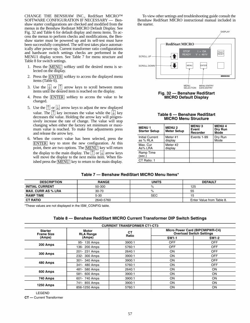
57
CHANGE THE BENSHAW INC., RediStart MICRO™SOFTWARE CONFIGURATION IF NECESSARY — Ben-shaw starter configurations are checked and modified from themenus in the Benshaw Redistart MICRO Default Display. SeeFig. 32 and Table 6 for default display and menu items. To ac-cess the menus to perform checks and modifications, the Ben-shaw starter must be powered up and its self-test must havebeen successfully completed. The self-test takes place automat-ically after power-up. Current transformer ratio configurationsand hardware switch settings checks are performed in theMENU1 display screen. See Table 7 for menu structure andTable 8 for switch settings.
1. Press the softkey until the desired menu is se-lected on the display.
2. Press the softkey to access the displayed menuitems (Table 6).
3. Use the or arrow keys to scroll between menuitems until the desired item is reached on the display.
4. Press the softkey to access the value to bechanged.
5. Use the or arrow keys to adjust the new displayedvalue. The key increases the value while the keydecreases the value. Holding the arrow key will progres-sively increase the rate of change. The value will stopchanging when either the factory set minimum or maxi-mum value is reached. To make fine adjustments pressand release the arrow key.
6. When the correct value has been selected, press the key to store the new configuration. At this
point, there are two options. The key will returnthe display to the main display. The or arrow keyswill move the display to the next menu item. When fin-ished press the key to return to the main display.
To view other settings and troubleshooting guide consult theBenshaw RediStart MICRO instructional manual included inthe starter.
Table 6 — Benshaw RediStart MICRO Menu Structure
Table 7 — Benshaw RediStart MICRO Menu Items*
*These values are not displayed in the ISM_CONFIG table.
Table 8 — Benshaw RediStart MICRO Current Transformer DIP Switch Settings
LEGENDCT — Current Transformer
MENU
ENTER
↓ ↑
ENTER
↑ ↓↑ ↓
ENTERMENU
↑ ↓
MENU
MENU 1Starter Setup
MENU 2Meter Setup
MENU 3Event Recorder
MENU 4Dry Run Mode
Initial Current as % RLA
Meter #1 display
Events 1-99 Dry Run Mode
Max. CurAs% LRA
Meter #2 display
Ramp Time (sec.)CT Ratio: 1
DESCRIPTION RANGE UNITS DEFAULTINITIAL CURRENT 50-300 % 125MAX. CURR AS % LRA 30-70 % 55RAMP TIME 5-30 SEC 15CT RATIO 2640-5760 Enter Value from Table 8.
CURRENT TRANSFORMER CT1-CT3
StarterFrame Size
(Amps)
MotorRLA Range
(Amps)
CTRatio
MIcro Power Card (BIPCMIPWR-C4)Overload Switch Settings
SW1-1 SW1-2
200 Amps95- 135 Amps 3900:1 OFF OFF
136- 200 Amps 5760:1 OFF OFF
300 Amps201- 231 Amps 2640:1 ON OFF232- 300 Amps 3900:1 ON OFF
480 Amps301- 340 Amps 3900:1 ON OFF341- 480 Amps 5760:1 ON OFF
600 Amps481- 580 Amps 2640:1 ON ON581- 600 Amps 3900:1 ON ON
740 Amps 601- 740 Amps 3900:1 ON ON
1250 Amps741- 855 Amps 3900:1 ON ON856-1250 Amps 5760:1 ON ON
FAULTRESET
MENU ENTER
DISPLAY
SCROLL UP
SCROLL DOWN
MENUSELECTION
MENU ENTRYDATA ENTRY
STOP I = OAREADY V = 461V
RediStart MICRO
Fig. 32 — Benshaw RediStart MICRO Default Display
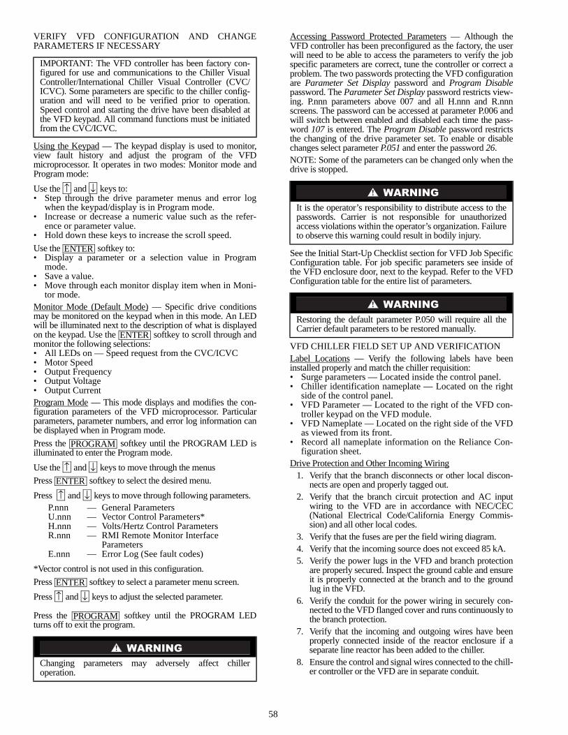
58
VERIFY VFD CONFIGURATION AND CHANGEPARAMETERS IF NECESSARY
Using the Keypad — The keypad display is used to monitor,view fault history and adjust the program of the VFDmicroprocessor. It operates in two modes: Monitor mode andProgram mode:
Use the and keys to:• Step through the drive parameter menus and error log
when the keypad/display is in Program mode.• Increase or decrease a numeric value such as the refer-
ence or parameter value.• Hold down these keys to increase the scroll speed.
Use the softkey to:• Display a parameter or a selection value in Program
mode.• Save a value.• Move through each monitor display item when in Moni-
tor mode.Monitor Mode (Default Mode) — Specific drive conditionsmay be monitored on the keypad when in this mode. An LEDwill be illuminated next to the description of what is displayedon the keypad. Use the softkey to scroll through andmonitor the following selections:• All LEDs on — Speed request from the CVC/ICVC• Motor Speed• Output Frequency• Output Voltage• Output CurrentProgram Mode — This mode displays and modifies the con-figuration parameters of the VFD microprocessor. Particularparameters, parameter numbers, and error log information canbe displayed when in Program mode.
Press the softkey until the PROGRAM LED isilluminated to enter the Program mode.
Use the and keys to move through the menus
Press softkey to select the desired menu.
Press and keys to move through following parameters.
*Vector control is not used in this configuration.
Press softkey to select a parameter menu screen.
Press and keys to adjust the selected parameter.
Press the softkey until the PROGRAM LEDturns off to exit the program.
Accessing Password Protected Parameters — Although theVFD controller has been preconfigured as the factory, the userwill need to be able to access the parameters to verify the jobspecific parameters are correct, tune the controller or correct aproblem. The two passwords protecting the VFD configurationare Parameter Set Display password and Program Disablepassword. The Parameter Set Display password restricts view-ing. P.nnn parameters above 007 and all H.nnn and R.nnnscreens. The password can be accessed at parameter P.006 andwill switch between enabled and disabled each time the pass-word 107 is entered. The Program Disable password restrictsthe changing of the drive parameter set. To enable or disablechanges select parameter P.051 and enter the password 26.NOTE: Some of the parameters can be changed only when thedrive is stopped.
See the Initial Start-Up Checklist section for VFD Job SpecificConfiguration table. For job specific parameters see inside ofthe VFD enclosure door, next to the keypad. Refer to the VFDConfiguration table for the entire list of parameters.
VFD CHILLER FIELD SET UP AND VERIFICATIONLabel Locations — Verify the following labels have beeninstalled properly and match the chiller requisition:• Surge parameters — Located inside the control panel.• Chiller identification nameplate — Located on the right
side of the control panel.• VFD Parameter — Located to the right of the VFD con-
troller keypad on the VFD module.• VFD Nameplate — Located on the right side of the VFD
as viewed from its front.• Record all nameplate information on the Reliance Con-
figuration sheet.Drive Protection and Other Incoming Wiring
1. Verify that the branch disconnects or other local discon-nects are open and properly tagged out.
2. Verify that the branch circuit protection and AC inputwiring to the VFD are in accordance with NEC/CEC(National Electrical Code/California Energy Commis-sion) and all other local codes.
3. Verify that the fuses are per the field wiring diagram.4. Verify that the incoming source does not exceed 85 kA.5. Verify the power lugs in the VFD and branch protection
are properly secured. Inspect the ground cable and ensureit is properly connected at the branch and to the groundlug in the VFD.
6. Verify the conduit for the power wiring in securely con-nected to the VFD flanged cover and runs continuously tothe branch protection.
7. Verify that the incoming and outgoing wires have beenproperly connected inside of the reactor enclosure if aseparate line reactor has been added to the chiller.
8. Ensure the control and signal wires connected to the chill-er controller or the VFD are in separate conduit.
IMPORTANT: The VFD controller has been factory con-figured for use and communications to the Chiller VisualController/International Chiller Visual Controller (CVC/ICVC). Some parameters are specific to the chiller config-uration and will need to be verified prior to operation.Speed control and starting the drive have been disabled atthe VFD keypad. All command functions must be initiatedfrom the CVC/ICVC.
P.nnn — General ParametersU.nnn — Vector Control Parameters*H.nnn — Volts/Hertz Control ParametersR.nnn — RMI Remote Monitor Interface
ParametersE.nnn — Error Log (See fault codes)
Changing parameters may adversely affect chilleroperation.
↑ ↓
ENTER
ENTER
PROGRAM
↑ ↓ENTER
↑ ↓
ENTER
↑ ↓
PROGRAM
It is the operator’s responsibility to distribute access to thepasswords. Carrier is not responsible for unauthorizedaccess violations within the operator’s organization. Failureto observe this warning could result in bodily injury.
Restoring the default parameter P.050 will require all theCarrier default parameters to be restored manually.
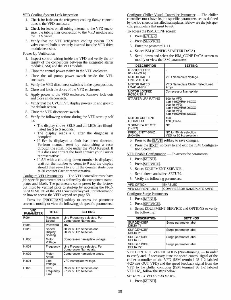
59
VFD Cooling System Leak Inspection1. Check for leaks on the refrigerant cooling flange connec-
tions to the VFD enclosure.2. Check for leaks on all tubing internal to the VFD enclo-
sure, the tubing flair connection to the VFD module andthe TXV valve.
3. Verify that the VFD refrigerant cooling system TXVvalve control bulb is securely inserted into the VFD drivemodule heat sink.
Power Up Verification1. Inspect control wiring inside the VFD and verify the in-
tegrity of the connections between the integrated startermodule (ISM) and the VFD module.
2. Close the control power switch in the VFD enclosure.3. Close the oil pump power switch inside the VFD
enclosure.4. Verify the VFD disconnect switch is in the open position.5. Close and latch the doors of the VFD enclosure.6. Apply power to the VFD enclosure. Remove lock outs
and close all disconnects.7. Verify that the CVC/ICVC display powers up and goes to
the default screen.8. Close the VFD disconnect switch.9. Verify the following actions during the VFD start-up self
test: • The display shows SELF and all LEDs are illumi-
nated for 5 to 6 seconds. • The display reads a 0 after the diagnosis is
complete. • If Err is displayed a fault has been detected.
Perform manual reset by establishing a resetthrough the small hole under the VFD Keypad. Ifthis does not correct the fault contact your Carrierrepresentative.
• If AR with a counting down number is displayedwait for the number to count to 0 and the displayshould then revert to a 0. If the counter starts overat 30 contact Carrier representative.
Configure VFD Parameters — The VFD controller must havejob specific parameters set as defined by the component name-plates and labels. The parameters come preset by the factory,but must be verified prior to start-up by accessing the PRO-GRAM MODE of the VFD controller keypad. For informationon how to access the VFD keypad see page 58.
Press the softkey to access the parameterscreen to modify or view the following job specific parameters:.
Configure Chiller Visual Controller Parameter — The chillercontroller must have its job specific parameters set as definedby the job sheet or installed nameplates. Below are the job spe-cific parameters that must be set:To access the ISM_CONF screen:
1. Press .2. Press .3. Enter the password 1111.4. Select ISM (CONFIG STARTER DATA)5. Scroll down and select the ISM_CONF DATA screen to
modify or view the ISM parameters:
6. Press to the softkey to save changes.7. Press the softkey to and exit the ISM Configura-
tion Screen.VFD Enable Configuration — To access the parameters:
1. Press .2. Press .3. Select EQUIPMENT SERVICE.4. Scroll down and select SETUP2.5. Verify the following parameters:
Configure Surge Parameters1. Press .2. Press .3. Select EQUIPMENT SERVICE and OPTIONS to verify
the following:
VFD CONTROL VERFICATION (Non-Running) — In orderto verify and, if necessary, tune the speed control signal of thechiller controller to the VFD (ISM terminal J8 1-2 labeled4-20 mA OUT VFD) and the speed feedback signal from theVFD to the chiller controller (ISM terminal J6 1-2 labeledVFD HZ), follow the steps below.Set TARGET VFD SPEED to 0%.
1. Press .
VFD PARAMETER TITLE SETTING
P.004 Maximum Speed
Line Frequency selected. Per Compressor Nameplate.
P.006 Password 107P.028 Speed
Display Scaling
60 for 60 Hz selection and50 for 50 Hz selection
H.000 MotorVoltage
Compressor nameplate voltage.
H.001 Frequency Line Frequency selected. Per Compressor Nameplate.
H.002 MotorAmps
Compressor nameplate amps.
H.021 LineVoltage
VFD nameplate voltage.
H.022 Over Frequency Limit
69 for 60 Hz selection and57 for 50 Hz selection.
PROGRAM
DESCRIPTION SETTINGSTARTER TYPE (2 = SS/VFD)
2
MOTOR RATED LINE VOLTAGE
VFD Nameplate Voltage.
MOTOR RATED LOAD AMPS
VFD Nameplate Chiller Rated Load Amps
MOTOR LOCKED ROTOR TRIP
Compressor Nameplate
STARTER LRA RATING 600 for VFDpart #19XVR0414XXX700 for VFD part #19XVR0500XXX 900 for VFD part #19XVR0643XXX
MOTOR CURRENT CT RATIO:1
163120 (414A)
3 GRND FAULT CT? (1=NO)
NO
FREQUENCY-60HZ (NO=50)
NO for 50 Hz selectionYES for 60 Hz selection
VFD OPTION ENABLEDVFD CURRENT LIMIT COMPRESSOR NAMEPLATE AMPS
DESCRIPTION SETTINGSSURGE/HGBPDELTA T1
Surge parameter label
SURGE/HGBPDELTA P1
Surge parameter label
SURGE/HGBPDELTA T2
Surge parameter label
SURGE/HGBPDELTA P2
Surge parameter label
ENTERSERVICE
SAVEEXIT
MENUSERVICE
MENUSERVICE
MENU
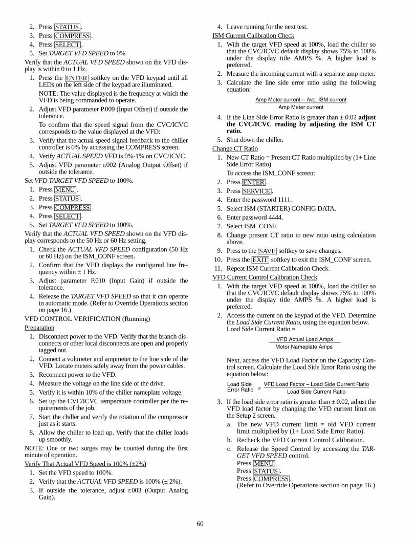
60
2. Press .3. Press .4. Press .5. Set TARGET VFD SPEED to 0%.
Verify that the ACTUAL VFD SPEED shown on the VFD dis-play is within 0 to 1 Hz.
1. Press the softkey on the VFD keypad until allLEDs on the left side of the keypad are illuminated.NOTE: The value displayed is the frequency at which theVFD is being commanded to operate.
2. Adjust VFD parameter P.009 (Input Offset) if outside thetolerance.To confirm that the speed signal from the CVC/ICVCcorresponds to the value displayed at the VFD:
3. Verify that the actual speed signal feedback to the chillercontroller is 0% by accessing the COMPRESS screen.
4. Verify ACTUAL SPEED VFD is 0%-1% on CVC/ICVC.5. Adjust VFD parameter r.002 (Analog Output Offset) if
outside the tolerance.Set VFD TARGET VFD SPEED to 100%.
1. Press .2. Press .3. Press .4. Press .5. Set TARGET VFD SPEED to 100%.
Verify that the ACTUAL VFD SPEED shown on the VFD dis-play corresponds to the 50 Hz or 60 Hz setting.
1. Check the ACTUAL VFD SPEED configuration (50 Hzor 60 Hz) on the ISM_CONF screen.
2. Confirm that the VFD displays the configured line fre-quency within ± 1 Hz.
3. Adjust parameter P.010 (Input Gain) if outside thetolerance.
4. Release the TARGET VFD SPEED so that it can operatein automatic mode. (Refer to Override Operations sectionon page 16.)
VFD CONTROL VERIFICATION (Running)Preparation
1. Disconnect power to the VFD. Verify that the branch dis-connects or other local disconnects are open and properlytagged out.
2. Connect a voltmeter and ampmeter to the line side of theVFD. Locate meters safely away from the power cables.
3. Reconnect power to the VFD.4. Measure the voltage on the line side of the drive.5. Verify it is within 10% of the chiller nameplate voltage.6. Set up the CVC/ICVC temperature controller per the re-
quirements of the job.7. Start the chiller and verify the rotation of the compressor
just as it starts.8. Allow the chiller to load up. Verify that the chiller loads
up smoothly.NOTE: One or two surges may be counted during the firstminute of operation.Verify That Actual VFD Speed is 100% (±2%)
1. Set the VFD speed to 100%.2. Verify that the ACTUAL VFD SPEED is 100% (± 2%).3. If outside the tolerance, adjust r.003 (Output Analog
Gain).
4. Leave running for the next test.ISM Current Calibration Check
1. With the target VFD speed at 100%, load the chiller sothat the CVC/ICVC default display shows 75% to 100%under the display title AMPS %. A higher load ispreferred.
2. Measure the incoming current with a separate amp meter.3. Calculate the line side error ratio using the following
equation:
4. If the Line Side Error Ratio is greater than ± 0.02 adjustthe CVC/ICVC reading by adjusting the ISM CTratio.
5. Shut down the chiller.Change CT Ratio
1. New CT Ratio = Present CT Ratio multiplied by (1+ LineSide Error Ratio). To access the ISM_CONF screen:
2. Press .3. Press .4. Enter the password 1111.5. Select ISM (STARTER) CONFIG DATA.6. Enter password 4444.7. Select ISM_CONF.8. Change present CT ratio to new ratio using calculation
above.9. Press to the softkey to save changes.
10. Press the softkey to exit the ISM_CONF screen.11. Repeat ISM Current Calibration Check.
VFD Current Control Calibration Check1. With the target VFD speed at 100%, load the chiller so
that the CVC/ICVC default display shows 75% to 100%under the display title AMPS %. A higher load ispreferred.
2. Access the current on the keypad of the VFD. Determinethe Load Side Current Ratio, using the equation below.Load Side Current Ratio =
Next, access the VFD Load Factor on the Capacity Con-trol screen. Calculate the Load Side Error Ratio using theequation below:
3. If the load side error ratio is greater than ± 0.02, adjust theVFD load factor by changing the VFD current limit onthe Setup 2 screen.a. The new VFD current limit = old VFD current
limit multiplied by (1+ Load Side Error Ratio).b. Recheck the VFD Current Control Calibration.c. Release the Speed Control by accessing the TAR-
GET VFD SPEED control.Press .Press .Press .(Refer to Override Operations section on page 16.)
STATUSCOMPRESSSELECT
ENTER
MENUSTATUSCOMPRESSSELECT
Amp Meter current – Ave. ISM currentAmp Meter current
VFD Actual Load Amps Motor Nameplate Amps
Load SideError Ratio =
VFD Load Factor – Load Side Current RatioLoad Side Current Ratio
ENTERSERVICE
SAVEEXIT
MENUSTATUSCOMPRESS
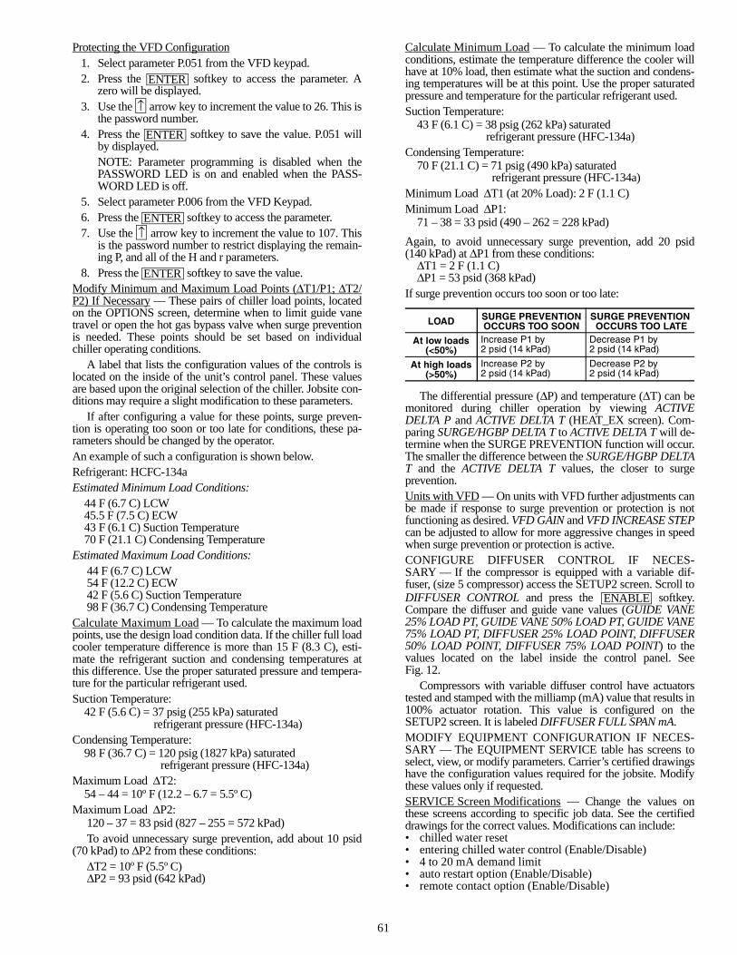
61
Protecting the VFD Configuration1. Select parameter P.051 from the VFD keypad.2. Press the softkey to access the parameter. A
zero will be displayed.3. Use the arrow key to increment the value to 26. This is
the password number.4. Press the softkey to save the value. P.051 will
by displayed.NOTE: Parameter programming is disabled when thePASSWORD LED is on and enabled when the PASS-WORD LED is off.
5. Select parameter P.006 from the VFD Keypad.6. Press the softkey to access the parameter.7. Use the arrow key to increment the value to 107. This
is the password number to restrict displaying the remain-ing P, and all of the H and r parameters.
8. Press the softkey to save the value.Modify Minimum and Maximum Load Points (∆T1/P1; ∆T2/P2) If Necessary — These pairs of chiller load points, locatedon the OPTIONS screen, determine when to limit guide vanetravel or open the hot gas bypass valve when surge preventionis needed. These points should be set based on individualchiller operating conditions.
A label that lists the configuration values of the controls islocated on the inside of the unit’s control panel. These valuesare based upon the original selection of the chiller. Jobsite con-ditions may require a slight modification to these parameters.
If after configuring a value for these points, surge preven-tion is operating too soon or too late for conditions, these pa-rameters should be changed by the operator.An example of such a configuration is shown below.Refrigerant: HCFC-134aEstimated Minimum Load Conditions:
44 F (6.7 C) LCW45.5 F (7.5 C) ECW43 F (6.1 C) Suction Temperature70 F (21.1 C) Condensing Temperature
Estimated Maximum Load Conditions:44 F (6.7 C) LCW54 F (12.2 C) ECW42 F (5.6 C) Suction Temperature98 F (36.7 C) Condensing Temperature
Calculate Maximum Load — To calculate the maximum loadpoints, use the design load condition data. If the chiller full loadcooler temperature difference is more than 15 F (8.3 C), esti-mate the refrigerant suction and condensing temperatures atthis difference. Use the proper saturated pressure and tempera-ture for the particular refrigerant used.Suction Temperature:
42 F (5.6 C) = 37 psig (255 kPa) saturatedrefrigerant pressure (HFC-134a)
Condensing Temperature:98 F (36.7 C) = 120 psig (1827 kPa) saturated
refrigerant pressure (HFC-134a)Maximum Load ∆T2:
54 – 44 = 10º F (12.2 – 6.7 = 5.5º C)Maximum Load ∆P2:
120 – 37 = 83 psid (827 – 255 = 572 kPad)To avoid unnecessary surge prevention, add about 10 psid
(70 kPad) to ∆P2 from these conditions:∆T2 = 10º F (5.5º C)∆P2 = 93 psid (642 kPad)
Calculate Minimum Load — To calculate the minimum loadconditions, estimate the temperature difference the cooler willhave at 10% load, then estimate what the suction and condens-ing temperatures will be at this point. Use the proper saturatedpressure and temperature for the particular refrigerant used.Suction Temperature:
43 F (6.1 C) = 38 psig (262 kPa) saturatedrefrigerant pressure (HFC-134a)
Condensing Temperature:70 F (21.1 C) = 71 psig (490 kPa) saturated
refrigerant pressure (HFC-134a)Minimum Load ∆T1 (at 20% Load): 2 F (1.1 C)Minimum Load ∆P1:
71 – 38 = 33 psid (490 – 262 = 228 kPad)
Again, to avoid unnecessary surge prevention, add 20 psid(140 kPad) at ∆P1 from these conditions:
∆T1 = 2 F (1.1 C)∆P1 = 53 psid (368 kPad)
If surge prevention occurs too soon or too late:
The differential pressure (∆P) and temperature (∆T) can bemonitored during chiller operation by viewing ACTIVEDELTA P and ACTIVE DELTA T (HEAT_EX screen). Com-paring SURGE/HGBP DELTA T to ACTIVE DELTA T will de-termine when the SURGE PREVENTION function will occur.The smaller the difference between the SURGE/HGBP DELTAT and the ACTIVE DELTA T values, the closer to surgeprevention.Units with VFD — On units with VFD further adjustments canbe made if response to surge prevention or protection is notfunctioning as desired. VFD GAIN and VFD INCREASE STEPcan be adjusted to allow for more aggressive changes in speedwhen surge prevention or protection is active.CONFIGURE DIFFUSER CONTROL IF NECES-SARY — If the compressor is equipped with a variable dif-fuser, (size 5 compressor) access the SETUP2 screen. Scroll toDIFFUSER CONTROL and press the softkey.Compare the diffuser and guide vane values (GUIDE VANE25% LOAD PT, GUIDE VANE 50% LOAD PT, GUIDE VANE75% LOAD PT, DIFFUSER 25% LOAD POINT, DIFFUSER50% LOAD POINT, DIFFUSER 75% LOAD POINT) to thevalues located on the label inside the control panel. SeeFig. 12.
Compressors with variable diffuser control have actuatorstested and stamped with the milliamp (mA) value that results in100% actuator rotation. This value is configured on theSETUP2 screen. It is labeled DIFFUSER FULL SPAN mA.MODIFY EQUIPMENT CONFIGURATION IF NECES-SARY — The EQUIPMENT SERVICE table has screens toselect, view, or modify parameters. Carrier’s certified drawingshave the configuration values required for the jobsite. Modifythese values only if requested.SERVICE Screen Modifications — Change the values onthese screens according to specific job data. See the certifieddrawings for the correct values. Modifications can include:• chilled water reset• entering chilled water control (Enable/Disable)• 4 to 20 mA demand limit• auto restart option (Enable/Disable)• remote contact option (Enable/Disable)
ENTER
↑
ENTER
ENTER↑
ENTER
LOAD SURGE PREVENTIONOCCURS TOO SOON
SURGE PREVENTION OCCURS TOO LATE
At low loads(<50%)
Increase P1 by2 psid (14 kPad)
Decrease P1 by2 psid (14 kPad)
At high loads(>50%)
Increase P2 by2 psid (14 kPad)
Decrease P2 by2 psid (14 kPad)
ENABLE
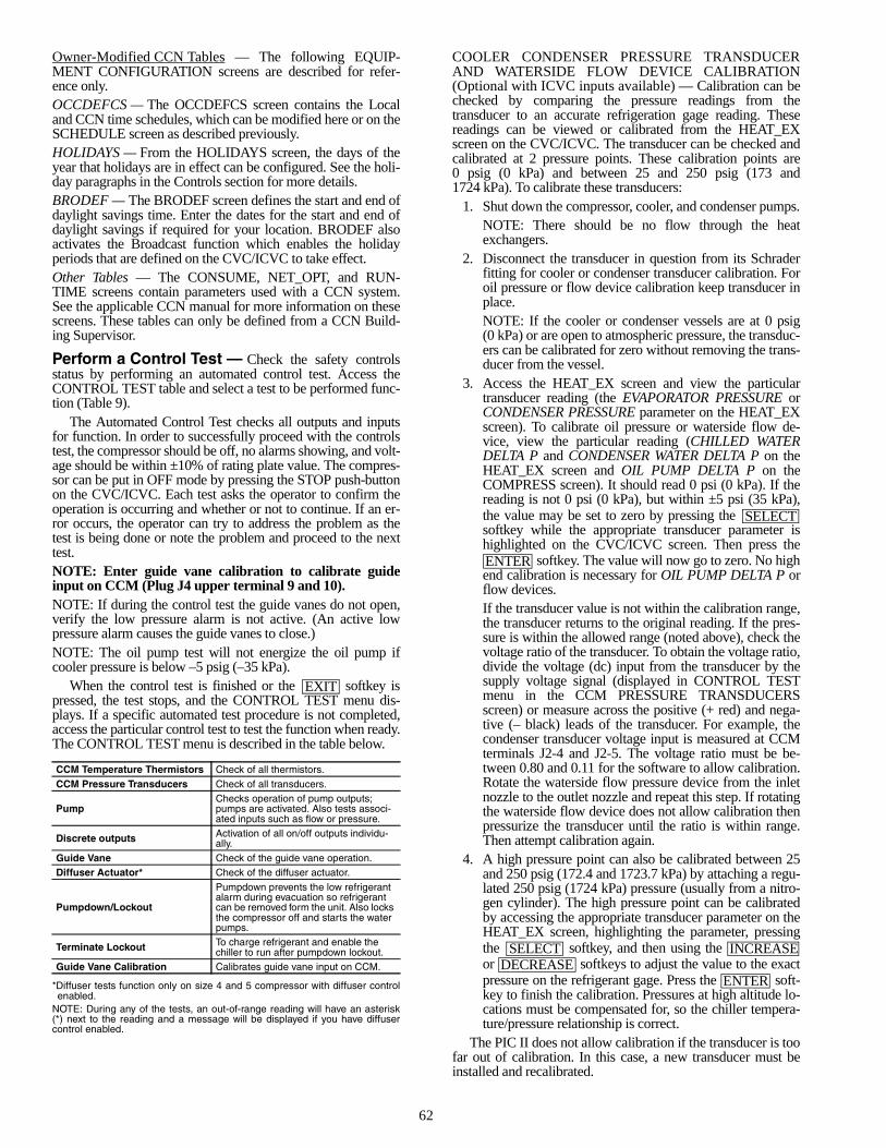
62
Owner-Modified CCN Tables — The following EQUIP-MENT CONFIGURATION screens are described for refer-ence only.OCCDEFCS — The OCCDEFCS screen contains the Localand CCN time schedules, which can be modified here or on theSCHEDULE screen as described previously.HOLIDAYS — From the HOLIDAYS screen, the days of theyear that holidays are in effect can be configured. See the holi-day paragraphs in the Controls section for more details.BRODEF — The BRODEF screen defines the start and end ofdaylight savings time. Enter the dates for the start and end ofdaylight savings if required for your location. BRODEF alsoactivates the Broadcast function which enables the holidayperiods that are defined on the CVC/ICVC to take effect.Other Tables — The CONSUME, NET_OPT, and RUN-TIME screens contain parameters used with a CCN system.See the applicable CCN manual for more information on thesescreens. These tables can only be defined from a CCN Build-ing Supervisor.
Perform a Control Test — Check the safety controlsstatus by performing an automated control test. Access theCONTROL TEST table and select a test to be performed func-tion (Table 9).
The Automated Control Test checks all outputs and inputsfor function. In order to successfully proceed with the controlstest, the compressor should be off, no alarms showing, and volt-age should be within ±10% of rating plate value. The compres-sor can be put in OFF mode by pressing the STOP push-buttonon the CVC/ICVC. Each test asks the operator to confirm theoperation is occurring and whether or not to continue. If an er-ror occurs, the operator can try to address the problem as thetest is being done or note the problem and proceed to the nexttest.NOTE: Enter guide vane calibration to calibrate guideinput on CCM (Plug J4 upper terminal 9 and 10).NOTE: If during the control test the guide vanes do not open,verify the low pressure alarm is not active. (An active lowpressure alarm causes the guide vanes to close.)NOTE: The oil pump test will not energize the oil pump ifcooler pressure is below –5 psig (–35 kPa).
When the control test is finished or the softkey ispressed, the test stops, and the CONTROL TEST menu dis-plays. If a specific automated test procedure is not completed,access the particular control test to test the function when ready.The CONTROL TEST menu is described in the table below.
*Diffuser tests function only on size 4 and 5 compressor with diffuser controlenabled.
NOTE: During any of the tests, an out-of-range reading will have an asterisk(*) next to the reading and a message will be displayed if you have diffusercontrol enabled.
COOLER CONDENSER PRESSURE TRANSDUCERAND WATERSIDE FLOW DEVICE CALIBRATION(Optional with ICVC inputs available) — Calibration can bechecked by comparing the pressure readings from thetransducer to an accurate refrigeration gage reading. Thesereadings can be viewed or calibrated from the HEAT_EXscreen on the CVC/ICVC. The transducer can be checked andcalibrated at 2 pressure points. These calibration points are0 psig (0 kPa) and between 25 and 250 psig (173 and1724 kPa). To calibrate these transducers:
1. Shut down the compressor, cooler, and condenser pumps.NOTE: There should be no flow through the heatexchangers.
2. Disconnect the transducer in question from its Schraderfitting for cooler or condenser transducer calibration. Foroil pressure or flow device calibration keep transducer inplace.NOTE: If the cooler or condenser vessels are at 0 psig(0 kPa) or are open to atmospheric pressure, the transduc-ers can be calibrated for zero without removing the trans-ducer from the vessel.
3. Access the HEAT_EX screen and view the particulartransducer reading (the EVAPORATOR PRESSURE orCONDENSER PRESSURE parameter on the HEAT_EXscreen). To calibrate oil pressure or waterside flow de-vice, view the particular reading (CHILLED WATERDELTA P and CONDENSER WATER DELTA P on theHEAT_EX screen and OIL PUMP DELTA P on theCOMPRESS screen). It should read 0 psi (0 kPa). If thereading is not 0 psi (0 kPa), but within ±5 psi (35 kPa),the value may be set to zero by pressing the softkey while the appropriate transducer parameter ishighlighted on the CVC/ICVC screen. Then press the
softkey. The value will now go to zero. No highend calibration is necessary for OIL PUMP DELTA P orflow devices.If the transducer value is not within the calibration range,the transducer returns to the original reading. If the pres-sure is within the allowed range (noted above), check thevoltage ratio of the transducer. To obtain the voltage ratio,divide the voltage (dc) input from the transducer by thesupply voltage signal (displayed in CONTROL TESTmenu in the CCM PRESSURE TRANSDUCERSscreen) or measure across the positive (+ red) and nega-tive (– black) leads of the transducer. For example, thecondenser transducer voltage input is measured at CCMterminals J2-4 and J2-5. The voltage ratio must be be-tween 0.80 and 0.11 for the software to allow calibration.Rotate the waterside flow pressure device from the inletnozzle to the outlet nozzle and repeat this step. If rotatingthe waterside flow device does not allow calibration thenpressurize the transducer until the ratio is within range.Then attempt calibration again.
4. A high pressure point can also be calibrated between 25and 250 psig (172.4 and 1723.7 kPa) by attaching a regu-lated 250 psig (1724 kPa) pressure (usually from a nitro-gen cylinder). The high pressure point can be calibratedby accessing the appropriate transducer parameter on theHEAT_EX screen, highlighting the parameter, pressingthe softkey, and then using the or softkeys to adjust the value to the exactpressure on the refrigerant gage. Press the soft-key to finish the calibration. Pressures at high altitude lo-cations must be compensated for, so the chiller tempera-ture/pressure relationship is correct.
The PIC II does not allow calibration if the transducer is toofar out of calibration. In this case, a new transducer must beinstalled and recalibrated.
CCM Temperature Thermistors Check of all thermistors.
CCM Pressure Transducers Check of all transducers.
PumpChecks operation of pump outputs; pumps are activated. Also tests associ-ated inputs such as flow or pressure.
Discrete outputs Activation of all on/off outputs individu-ally.
Guide Vane Check of the guide vane operation.Diffuser Actuator* Check of the diffuser actuator.
Pumpdown/Lockout
Pumpdown prevents the low refrigerant alarm during evacuation so refrigerant can be removed form the unit. Also locks the compressor off and starts the water pumps.
Terminate Lockout To charge refrigerant and enable the chiller to run after pumpdown lockout.
Guide Vane Calibration Calibrates guide vane input on CCM.
EXIT
SELECT
ENTER
SELECT INCREASEDECREASE
ENTER
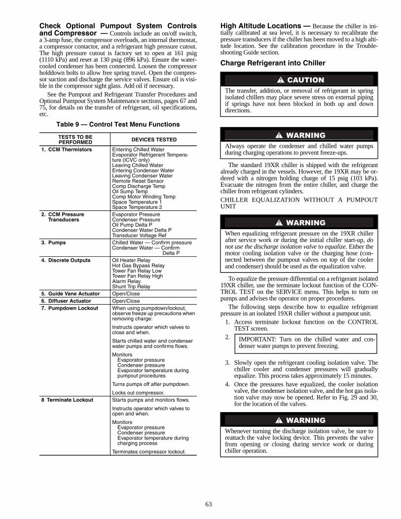
63
Check Optional Pumpout System Controlsand Compressor — Controls include an on/off switch,a 3-amp fuse, the compressor overloads, an internal thermostat,a compressor contactor, and a refrigerant high pressure cutout.The high pressure cutout is factory set to open at 161 psig(1110 kPa) and reset at 130 psig (896 kPa). Ensure the water-cooled condenser has been connected. Loosen the compressorholddown bolts to allow free spring travel. Open the compres-sor suction and discharge the service valves. Ensure oil is visi-ble in the compressor sight glass. Add oil if necessary.
See the Pumpout and Refrigerant Transfer Procedures andOptional Pumpout System Maintenance sections, pages 67 and75, for details on the transfer of refrigerant, oil specifications,etc.
Table 9 — Control Test Menu Functions
High Altitude Locations — Because the chiller is ini-tially calibrated at sea level, it is necessary to recalibrate thepressure transducers if the chiller has been moved to a high alti-tude location. See the calibration procedure in the Trouble-shooting Guide section.
Charge Refrigerant into Chiller
The standard 19XR chiller is shipped with the refrigerantalready charged in the vessels. However, the 19XR may be or-dered with a nitrogen holding charge of 15 psig (103 kPa).Evacuate the nitrogen from the entire chiller, and charge thechiller from refrigerant cylinders.CHILLER EQUALIZATION WITHOUT A PUMPOUTUNIT
To equalize the pressure differential on a refrigerant isolated19XR chiller, use the terminate lockout function of the CON-TROL TEST on the SERVICE menu. This helps to turn onpumps and advises the operator on proper procedures.
The following steps describe how to equalize refrigerantpressure in an isolated 19XR chiller without a pumpout unit.
1. Access terminate lockout function on the CONTROLTEST screen.
2.
3. Slowly open the refrigerant cooling isolation valve. Thechiller cooler and condenser pressures will graduallyequalize. This process takes approximately 15 minutes.
4. Once the pressures have equalized, the cooler isolationvalve, the condenser isolation valve, and the hot gas isola-tion valve may now be opened. Refer to Fig. 29 and 30,for the location of the valves.
TESTS TO BEPERFORMED DEVICES TESTED
1. CCM Thermistors Entering Chilled WaterEvaporator Refrigerant Tempera-ture (ICVC only)Leaving Chilled WaterEntering Condenser WaterLeaving Condenser WaterRemote Reset SensorComp Discharge TempOil Sump TempComp Motor Winding TempSpace Temperature 1Space Temperature 2
2. CCM Pressure Transducers
Evaporator PressureCondenser PressureOil Pump Delta PCondenser Water Delta PTransducer Voltage Ref
3. Pumps Chilled Water — Confirm pressureCondenser Water — Confirm
Delta P4. Discrete Outputs Oil Heater Relay
Hot Gas Bypass RelayTower Fan Relay LowTower Fan Relay HighAlarm RelayShunt Trip Relay
5. Guide Vane Actuator Open/Close6. Diffuser Actuator Open/Close7. Pumpdown Lockout When using pumpdown/lockout,
observe freeze up precautions when removing charge:
Instructs operator which valves to close and when.
Starts chilled water and condenser water pumps and confirms flows.
MonitorsEvaporator pressureCondenser pressureEvaporator temperature duringpumpout procedures
Turns pumps off after pumpdown.
Locks out compressor.8 Terminate Lockout Starts pumps and monitors flows.
Instructs operator which valves toopen and when.
MonitorsEvaporator pressureCondenser pressureEvaporator temperature duringcharging process
Terminates compressor lockout.
The transfer, addition, or removal of refrigerant in springisolated chillers may place severe stress on external pipingif springs have not been blocked in both up and downdirections.
Always operate the condenser and chilled water pumpsduring charging operations to prevent freeze-ups.
When equalizing refrigerant pressure on the 19XR chillerafter service work or during the initial chiller start-up, donot use the discharge isolation valve to equalize. Either themotor cooling isolation valve or the charging hose (con-nected between the pumpout valves on top of the coolerand condenser) should be used as the equalization valve.
Whenever turning the discharge isolation valve, be sure toreattach the valve locking device. This prevents the valvefrom opening or closing during service work or duringchiller operation.
IMPORTANT: Turn on the chilled water and con-denser water pumps to prevent freezing.
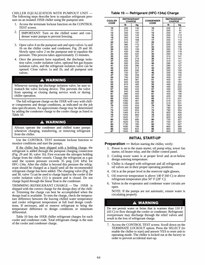
64
CHILLER EQUALIZATION WITH PUMPOUT UNIT —The following steps describe how to equalize refrigerant pres-sure on an isolated 19XR chiller using the pumpout unit.
1. Access the terminate lockout function on the CONTROLTEST screen.
2.
3. Open valve 4 on the pumpout unit and open valves 1a and1b on the chiller cooler and condenser, Fig. 29 and 30.Slowly open valve 2 on the pumpout unit to equalize thepressure. This process takes approximately 15 minutes.
4. Once the pressures have equalized, the discharge isola-tion valve, cooler isolation valve, optional hot gas bypassisolation valve, and the refrigerant isolation valve can beopened. Close valves 1a and 1b, and all pumpout unitvalves.
The full refrigerant charge on the 19XR will vary with chill-er components and design conditions, as indicated on the jobdata specifications. An approximate charge may be determinedby adding the condenser charge to the cooler charge as listed inTable 10.
Use the CONTROL TEST terminate lockout function tomonitor conditions and start the pumps.
If the chiller has been shipped with a holding charge, therefrigerant is added through the pumpout charging connection(Fig. 29 and 30, valve 1b). First evacuate the nitrogen holdingcharge from the chiller vessels. Charge the refrigerant as a gasuntil the system pressure exceeds 35 psig (141 kPa) forHFC-134a. After the chiller is beyond this pressure the refrig-erant should be charged as a liquid until all the recommendedrefrigerant charge has been added. The charging valve (Fig. 29and 30, valve 7) can be used to charge liquid to the cooler if thecooler isolation valve (11) is present and is closed. Do notcharge liquid through the linear float to the condenser.TRIMMING REFRIGERANT CHARGE — The 19XR isshipped with the correct charge for the design duty of the chill-er. Trimming the charge can best be accomplished when thedesign load is available. To trim the charge, check the tempera-ture difference between the leaving chilled water temperatureand cooler refrigerant temperature at full load design condi-tions. If necessary, add or remove refrigerant to bring thetemperature difference to design conditions or minimumdifferential.
Table 10 lists the 19XR chiller refrigerant charges for eachcooler and condenser code. Total refrigerant charge is the sumof the cooler and condenser charge.
Table 10 — Refrigerant (HFC-134a) Charge
INITIAL START-UP
Preparation — Before starting the chiller, verify:1. Power is on to the main starter, oil pump relay, tower fan
starter, oil heater relay, and the chiller control panel.2. Cooling tower water is at proper level and at-or-below
design entering temperature.3. Chiller is charged with refrigerant and all refrigerant and
oil valves are in their proper operating positions.4. Oil is at the proper level in the reservoir sight glasses.5. Oil reservoir temperature is above 140 F (60 C) or above
refrigerant temperature plus 50° F (28° C).6. Valves in the evaporator and condenser water circuits are
open.NOTE: If the pumps are not automatic, ensure water iscirculating properly.
7. Access the CONTROL TEST screen. Scroll down on theTERMINATE LOCKOUT option. Press the SELECT (toenable the chiller to start) and answer YES to reset unit tooperating mode. The chiller is locked out at the factory inorder to prevent accidental start-up.
Whenever turning the discharge isolation valve, be sure toreattach the valve locking device. This prevents the valvefrom opening or closing during service work or duringchiller operation.
Always operate the condenser and chilled water pumpswhenever charging, transferring, or removing refrigerantfrom the chiller.
IMPORTANT: Turn on the chilled water and con-denser water pumps to prevent freezing.
COOLERCODE
REFRIGERANTCHARGE CONDENSER
CODE
REFRIGERANTCHARGE
lb kg lb kg10 290 132 10 200 9111 310 141 11 200 9112 330 150 12 200 9115 320 145 15 250 11316 340 154 16 250 11317 370 168 17 250 11320 345 157 20 225 10221 385 175 21 225 10222 435 197 22 225 10230 350 159 30 260 11831 420 190 31 260 11832 490 222 32 260 11835 400 181 35 310 14136 480 218 36 310 14137 550 250 37 310 14140 560 254 40 280 12741 630 286 41 280 12742 690 313 42 280 12745 640 290 45 330 15046 720 327 46 330 15047 790 358 47 330 15050 750 340 50 400 18151 840 381 51 400 18152 900 408 52 400 18155 870 395 55 490 22256 940 426 56 490 22257 980 445 57 490 22260 940 426 60 420 19061 980 445 61 420 19062 1020 463 62 420 19065 1020 463 65 510 23166 1060 481 66 510 23167 1090 494 67 510 23170 1220 553 70 780 35471 1340 608 71 780 35472 1440 653 72 780 35475 1365 619 75 925 42076 1505 683 76 925 42077 1625 737 77 925 42080 1500 680 80 720 32781 1620 735 81 720 32782 1730 785 82 720 32785 1690 766 85 860 39086 1820 825 86 860 39087 1940 880 87 860 390
Do not permit water or brine that is warmer than 110 F(43 C) to flow through the cooler or condenser. Refrigerantoverpressure may discharge through the relief valves andresult in the loss of refrigerant charge.
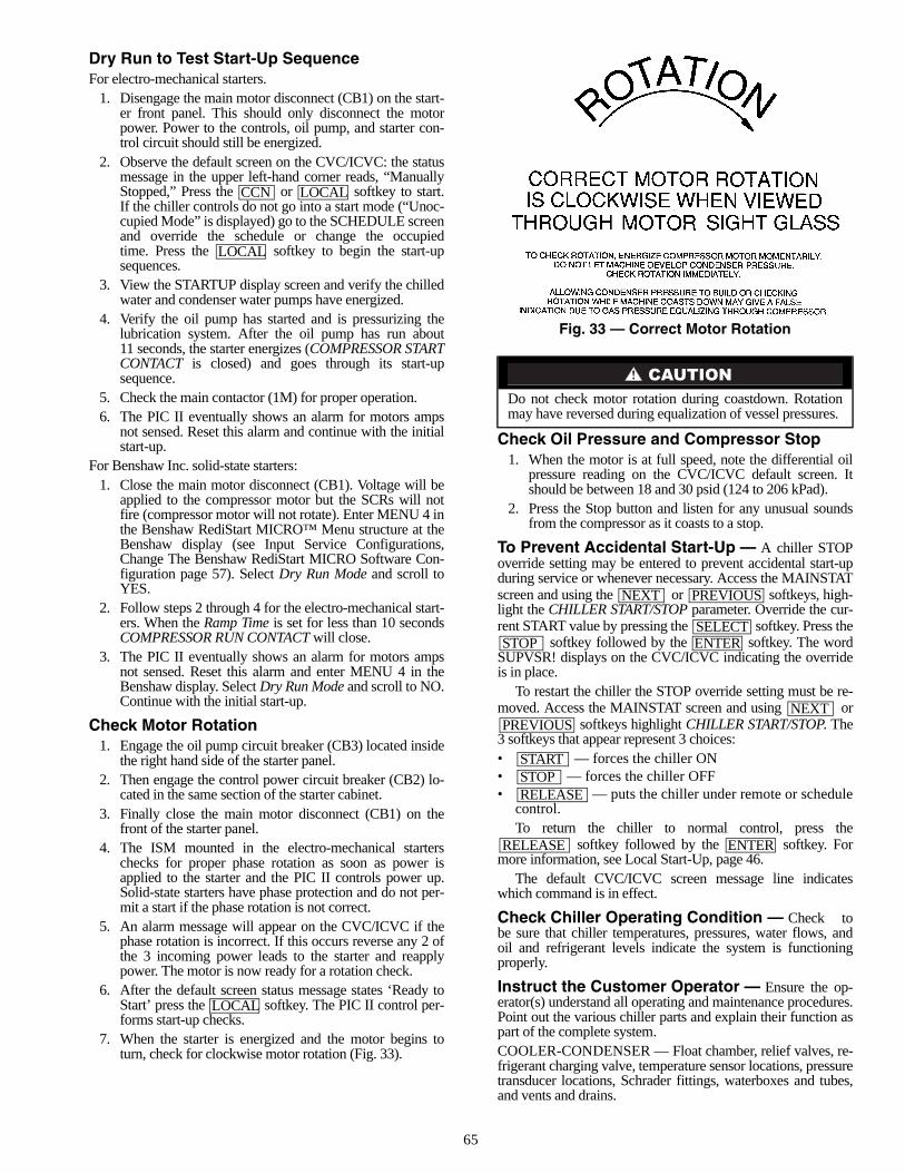
65
Dry Run to Test Start-Up SequenceFor electro-mechanical starters.
1. Disengage the main motor disconnect (CB1) on the start-er front panel. This should only disconnect the motorpower. Power to the controls, oil pump, and starter con-trol circuit should still be energized.
2. Observe the default screen on the CVC/ICVC: the statusmessage in the upper left-hand corner reads, “ManuallyStopped,” Press the or softkey to start.If the chiller controls do not go into a start mode (“Unoc-cupied Mode” is displayed) go to the SCHEDULE screenand override the schedule or change the occupiedtime. Press the softkey to begin the start-upsequences.
3. View the STARTUP display screen and verify the chilledwater and condenser water pumps have energized.
4. Verify the oil pump has started and is pressurizing thelubrication system. After the oil pump has run about11 seconds, the starter energizes (COMPRESSOR STARTCONTACT is closed) and goes through its start-upsequence.
5. Check the main contactor (1M) for proper operation.6. The PIC II eventually shows an alarm for motors amps
not sensed. Reset this alarm and continue with the initialstart-up.
For Benshaw Inc. solid-state starters:1. Close the main motor disconnect (CB1). Voltage will be
applied to the compressor motor but the SCRs will notfire (compressor motor will not rotate). Enter MENU 4 inthe Benshaw RediStart MICRO™ Menu structure at theBenshaw display (see Input Service Configurations,Change The Benshaw RediStart MICRO Software Con-figuration page 57). Select Dry Run Mode and scroll toYES.
2. Follow steps 2 through 4 for the electro-mechanical start-ers. When the Ramp Time is set for less than 10 secondsCOMPRESSOR RUN CONTACT will close.
3. The PIC II eventually shows an alarm for motors ampsnot sensed. Reset this alarm and enter MENU 4 in theBenshaw display. Select Dry Run Mode and scroll to NO.Continue with the initial start-up.
Check Motor Rotation1. Engage the oil pump circuit breaker (CB3) located inside
the right hand side of the starter panel.2. Then engage the control power circuit breaker (CB2) lo-
cated in the same section of the starter cabinet.3. Finally close the main motor disconnect (CB1) on the
front of the starter panel.4. The ISM mounted in the electro-mechanical starters
checks for proper phase rotation as soon as power isapplied to the starter and the PIC II controls power up.Solid-state starters have phase protection and do not per-mit a start if the phase rotation is not correct.
5. An alarm message will appear on the CVC/ICVC if thephase rotation is incorrect. If this occurs reverse any 2 ofthe 3 incoming power leads to the starter and reapplypower. The motor is now ready for a rotation check.
6. After the default screen status message states ‘Ready toStart’ press the softkey. The PIC II control per-forms start-up checks.
7. When the starter is energized and the motor begins toturn, check for clockwise motor rotation (Fig. 33).
Check Oil Pressure and Compressor Stop1. When the motor is at full speed, note the differential oil
pressure reading on the CVC/ICVC default screen. Itshould be between 18 and 30 psid (124 to 206 kPad).
2. Press the Stop button and listen for any unusual soundsfrom the compressor as it coasts to a stop.
To Prevent Accidental Start-Up — A chiller STOPoverride setting may be entered to prevent accidental start-upduring service or whenever necessary. Access the MAINSTATscreen and using the or softkeys, high-light the CHILLER START/STOP parameter. Override the cur-rent START value by pressing the softkey. Press the
softkey followed by the softkey. The wordSUPVSR! displays on the CVC/ICVC indicating the overrideis in place.
To restart the chiller the STOP override setting must be re-moved. Access the MAINSTAT screen and using or
softkeys highlight CHILLER START/STOP. The3 softkeys that appear represent 3 choices:• — forces the chiller ON• — forces the chiller OFF• — puts the chiller under remote or schedule
control.To return the chiller to normal control, press the
softkey followed by the softkey. Formore information, see Local Start-Up, page 46.
The default CVC/ICVC screen message line indicateswhich command is in effect.
Check Chiller Operating Condition — Check tobe sure that chiller temperatures, pressures, water flows, andoil and refrigerant levels indicate the system is functioningproperly.
Instruct the Customer Operator — Ensure the op-erator(s) understand all operating and maintenance procedures.Point out the various chiller parts and explain their function aspart of the complete system.COOLER-CONDENSER — Float chamber, relief valves, re-frigerant charging valve, temperature sensor locations, pressuretransducer locations, Schrader fittings, waterboxes and tubes,and vents and drains.
CCN LOCAL
LOCAL
LOCAL
Do not check motor rotation during coastdown. Rotationmay have reversed during equalization of vessel pressures.
NEXT PREVIOUS
SELECTSTOP ENTER
NEXTPREVIOUS
STARTSTOPRELEASE
RELEASE ENTER
Fig. 33 — Correct Motor Rotation
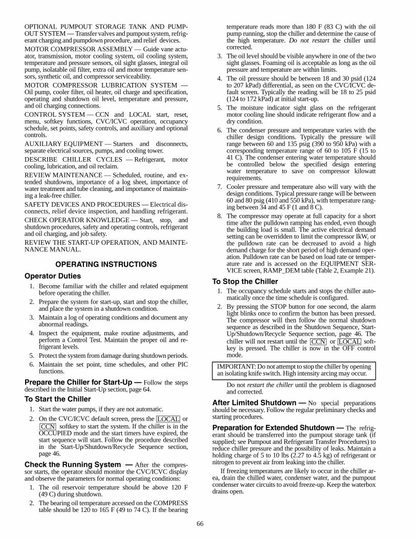
66
OPTIONAL PUMPOUT STORAGE TANK AND PUMP-OUT SYSTEM — Transfer valves and pumpout system, refrig-erant charging and pumpdown procedure, and relief devices.MOTOR COMPRESSOR ASSEMBLY — Guide vane actu-ator, transmission, motor cooling system, oil cooling system,temperature and pressure sensors, oil sight glasses, integral oilpump, isolatable oil filter, extra oil and motor temperature sen-sors, synthetic oil, and compressor serviceability.MOTOR COMPRESSOR LUBRICATION SYSTEM —Oil pump, cooler filter, oil heater, oil charge and specification,operating and shutdown oil level, temperature and pressure,and oil charging connections.CONTROL SYSTEM — CCN and LOCAL start, reset,menu, softkey functions, CVC/ICVC operation, occupancyschedule, set points, safety controls, and auxiliary and optionalcontrols.AUXILIARY EQUIPMENT — Starters and disconnects,separate electrical sources, pumps, and cooling tower.DESCRIBE CHILLER CYCLES — Refrigerant, motorcooling, lubrication, and oil reclaim.REVIEW MAINTENANCE — Scheduled, routine, and ex-tended shutdowns, importance of a log sheet, importance ofwater treatment and tube cleaning, and importance of maintain-ing a leak-free chiller.SAFETY DEVICES AND PROCEDURES — Electrical dis-connects, relief device inspection, and handling refrigerant.CHECK OPERATOR KNOWLEDGE — Start, stop, andshutdown procedures, safety and operating controls, refrigerantand oil charging, and job safety.REVIEW THE START-UP OPERATION, AND MAINTE-NANCE MANUAL.
OPERATING INSTRUCTIONS
Operator Duties1. Become familiar with the chiller and related equipment
before operating the chiller.2. Prepare the system for start-up, start and stop the chiller,
and place the system in a shutdown condition.3. Maintain a log of operating conditions and document any
abnormal readings.4. Inspect the equipment, make routine adjustments, and
perform a Control Test. Maintain the proper oil and re-frigerant levels.
5. Protect the system from damage during shutdown periods.6. Maintain the set point, time schedules, and other PIC
functions.
Prepare the Chiller for Start-Up — Follow the stepsdescribed in the Initial Start-Up section, page 64.
To Start the Chiller1. Start the water pumps, if they are not automatic.
2. On the CVC/ICVC default screen, press the or softkey to start the system. If the chiller is in the
OCCUPIED mode and the start timers have expired, thestart sequence will start. Follow the procedure describedin the Start-Up/Shutdown/Recycle Sequence section,page 46.
Check the Running System — After the compres-sor starts, the operator should monitor the CVC/ICVC displayand observe the parameters for normal operating conditions:
1. The oil reservoir temperature should be above 120 F(49 C) during shutdown.
2. The bearing oil temperature accessed on the COMPRESStable should be 120 to 165 F (49 to 74 C). If the bearing
temperature reads more than 180 F (83 C) with the oilpump running, stop the chiller and determine the cause ofthe high temperature. Do not restart the chiller untilcorrected.
3. The oil level should be visible anywhere in one of the twosight glasses. Foaming oil is acceptable as long as the oilpressure and temperature are within limits.
4. The oil pressure should be between 18 and 30 psid (124to 207 kPad) differential, as seen on the CVC/ICVC de-fault screen. Typically the reading will be 18 to 25 psid(124 to 172 kPad) at initial start-up.
5. The moisture indicator sight glass on the refrigerantmotor cooling line should indicate refrigerant flow and adry condition.
6. The condenser pressure and temperature varies with thechiller design conditions. Typically the pressure willrange between 60 and 135 psig (390 to 950 kPa) with acorresponding temperature range of 60 to 105 F (15 to41 C). The condenser entering water temperature shouldbe controlled below the specified design enteringwater temperature to save on compressor kilowattrequirements.
7. Cooler pressure and temperature also will vary with thedesign conditions. Typical pressure range will be between60 and 80 psig (410 and 550 kPa), with temperature rang-ing between 34 and 45 F (1 and 8 C).
8. The compressor may operate at full capacity for a shorttime after the pulldown ramping has ended, even thoughthe building load is small. The active electrical demandsetting can be overridden to limit the compressor IkW, orthe pulldown rate can be decreased to avoid a highdemand charge for the short period of high demand oper-ation. Pulldown rate can be based on load rate or temper-ature rate and is accessed on the EQUIPMENT SER-VICE screen, RAMP_DEM table (Table 2, Example 21).
To Stop the Chiller1. The occupancy schedule starts and stops the chiller auto-
matically once the time schedule is configured.2. By pressing the STOP button for one second, the alarm
light blinks once to confirm the button has been pressed.The compressor will then follow the normal shutdownsequence as described in the Shutdown Sequence, Start-Up/Shutdown/Recycle Sequence section, page 46. Thechiller will not restart until the or soft-key is pressed. The chiller is now in the OFF controlmode.
Do not restart the chiller until the problem is diagnosedand corrected.
After Limited Shutdown — No special preparationsshould be necessary. Follow the regular preliminary checks andstarting procedures.
Preparation for Extended Shutdown — The refrig-erant should be transferred into the pumpout storage tank (ifsupplied; see Pumpout and Refrigerant Transfer Procedures) toreduce chiller pressure and the possibility of leaks. Maintain aholding charge of 5 to 10 lbs (2.27 to 4.5 kg) of refrigerant ornitrogen to prevent air from leaking into the chiller.
If freezing temperatures are likely to occur in the chiller ar-ea, drain the chilled water, condenser water, and the pumpoutcondenser water circuits to avoid freeze-up. Keep the waterboxdrains open.
LOCALCCN
IMPORTANT: Do not attempt to stop the chiller by openingan isolating knife switch. High intensity arcing may occur.
CCN LOCAL
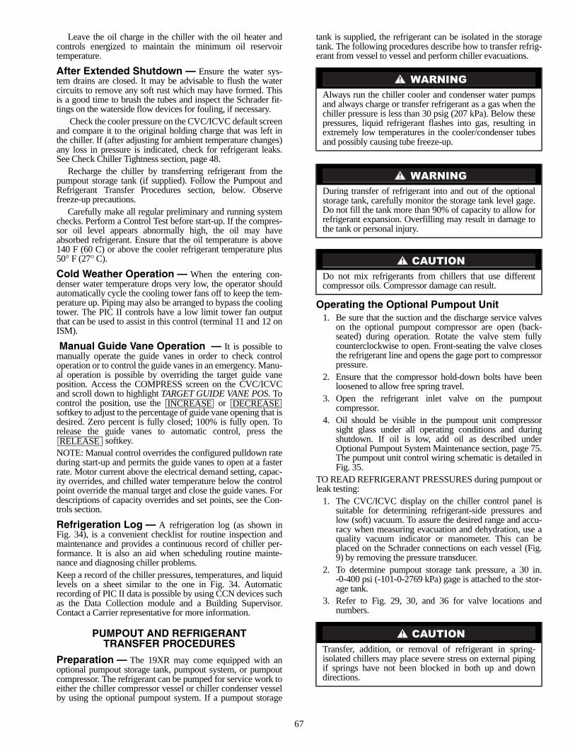
67
Leave the oil charge in the chiller with the oil heater andcontrols energized to maintain the minimum oil reservoirtemperature.
After Extended Shutdown — Ensure the water sys-tem drains are closed. It may be advisable to flush the watercircuits to remove any soft rust which may have formed. Thisis a good time to brush the tubes and inspect the Schrader fit-tings on the waterside flow devices for fouling, if necessary.
Check the cooler pressure on the CVC/ICVC default screenand compare it to the original holding charge that was left inthe chiller. If (after adjusting for ambient temperature changes)any loss in pressure is indicated, check for refrigerant leaks.See Check Chiller Tightness section, page 48.
Recharge the chiller by transferring refrigerant from thepumpout storage tank (if supplied). Follow the Pumpout andRefrigerant Transfer Procedures section, below. Observefreeze-up precautions.
Carefully make all regular preliminary and running systemchecks. Perform a Control Test before start-up. If the compres-sor oil level appears abnormally high, the oil may haveabsorbed refrigerant. Ensure that the oil temperature is above140 F (60 C) or above the cooler refrigerant temperature plus50° F (27° C).
Cold Weather Operation — When the entering con-denser water temperature drops very low, the operator shouldautomatically cycle the cooling tower fans off to keep the tem-perature up. Piping may also be arranged to bypass the coolingtower. The PIC II controls have a low limit tower fan outputthat can be used to assist in this control (terminal 11 and 12 onISM).
Manual Guide Vane Operation — It is possible tomanually operate the guide vanes in order to check controloperation or to control the guide vanes in an emergency. Manu-al operation is possible by overriding the target guide vaneposition. Access the COMPRESS screen on the CVC/ICVCand scroll down to highlight TARGET GUIDE VANE POS. Tocontrol the position, use the or softkey to adjust to the percentage of guide vane opening that isdesired. Zero percent is fully closed; 100% is fully open. Torelease the guide vanes to automatic control, press the
softkey.NOTE: Manual control overrides the configured pulldown rateduring start-up and permits the guide vanes to open at a fasterrate. Motor current above the electrical demand setting, capac-ity overrides, and chilled water temperature below the controlpoint override the manual target and close the guide vanes. Fordescriptions of capacity overrides and set points, see the Con-trols section.
Refrigeration Log — A refrigeration log (as shown inFig. 34), is a convenient checklist for routine inspection andmaintenance and provides a continuous record of chiller per-formance. It is also an aid when scheduling routine mainte-nance and diagnosing chiller problems.Keep a record of the chiller pressures, temperatures, and liquidlevels on a sheet similar to the one in Fig. 34. Automaticrecording of PIC II data is possible by using CCN devices suchas the Data Collection module and a Building Supervisor.Contact a Carrier representative for more information.
PUMPOUT AND REFRIGERANTTRANSFER PROCEDURES
Preparation — The 19XR may come equipped with anoptional pumpout storage tank, pumpout system, or pumpoutcompressor. The refrigerant can be pumped for service work toeither the chiller compressor vessel or chiller condenser vesselby using the optional pumpout system. If a pumpout storage
tank is supplied, the refrigerant can be isolated in the storagetank. The following procedures describe how to transfer refrig-erant from vessel to vessel and perform chiller evacuations.
Operating the Optional Pumpout Unit1. Be sure that the suction and the discharge service valves
on the optional pumpout compressor are open (back-seated) during operation. Rotate the valve stem fullycounterclockwise to open. Front-seating the valve closesthe refrigerant line and opens the gage port to compressorpressure.
2. Ensure that the compressor hold-down bolts have beenloosened to allow free spring travel.
3. Open the refrigerant inlet valve on the pumpoutcompressor.
4. Oil should be visible in the pumpout unit compressorsight glass under all operating conditions and duringshutdown. If oil is low, add oil as described underOptional Pumpout System Maintenance section, page 75.The pumpout unit control wiring schematic is detailed inFig. 35.
TO READ REFRIGERANT PRESSURES during pumpout orleak testing:
1. The CVC/ICVC display on the chiller control panel issuitable for determining refrigerant-side pressures andlow (soft) vacuum. To assure the desired range and accu-racy when measuring evacuation and dehydration, use aquality vacuum indicator or manometer. This can beplaced on the Schrader connections on each vessel (Fig.9) by removing the pressure transducer.
2. To determine pumpout storage tank pressure, a 30 in.-0-400 psi (-101-0-2769 kPa) gage is attached to the stor-age tank.
3. Refer to Fig. 29, 30, and 36 for valve locations andnumbers.
INCREASE DECREASE
RELEASE
Always run the chiller cooler and condenser water pumpsand always charge or transfer refrigerant as a gas when thechiller pressure is less than 30 psig (207 kPa). Below thesepressures, liquid refrigerant flashes into gas, resulting inextremely low temperatures in the cooler/condenser tubesand possibly causing tube freeze-up.
During transfer of refrigerant into and out of the optionalstorage tank, carefully monitor the storage tank level gage.Do not fill the tank more than 90% of capacity to allow forrefrigerant expansion. Overfilling may result in damage tothe tank or personal injury.
Do not mix refrigerants from chillers that use differentcompressor oils. Compressor damage can result.
Transfer, addition, or removal of refrigerant in spring-isolated chillers may place severe stress on external pipingif springs have not been blocked in both up and downdirections.
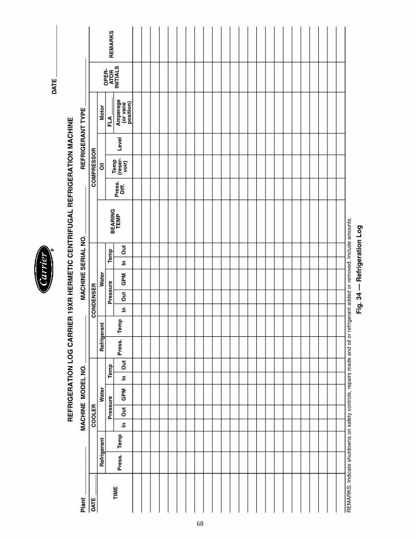
68
RE
FR
IGE
RA
TIO
N L
OG
CA
RR
IER
19X
R H
ER
ME
TIC
CE
NT
RIF
UG
AL
RE
FR
IGE
RA
TIO
N M
AC
HIN
E
Pla
nt
MA
CH
INE
MO
DE
L N
O.
MA
CH
INE
SE
RIA
L N
O.
RE
FR
IGE
RA
NT
TY
PE
RE
MA
RK
S: I
ndic
ate
shut
dow
ns o
n sa
fety
con
trol
s, r
epai
rs m
ade
and
oil o
r re
frig
eran
t add
ed o
r re
mov
ed. I
nclu
de a
mou
nts.
Fig
. 34
— R
efri
ger
atio
n L
og
DA
TE
CO
OL
ER
CO
ND
EN
SE
RC
OM
PR
ES
SO
R
OP
ER
-A
TOR
IN
ITIA
LS
RE
MA
RK
ST
IME
Ref
rig
eran
tW
ater
Ref
rig
eran
tW
ater
BE
AR
ING
TE
MP
Oil
Mo
tor
Pre
ss.
Tem
p
Pre
ssu
reTe
mp
Pre
ss.
Tem
p
Pre
ssu
reTe
mp
Pre
ss.
Dif
f.
Tem
p(r
eser
-vo
ir)
Lev
el
FL
A
InO
ut
GP
MIn
Ou
tIn
Ou
tG
PM
InO
ut
Am
per
age
(or
van
ep
osi
tio
n)
DA
TE
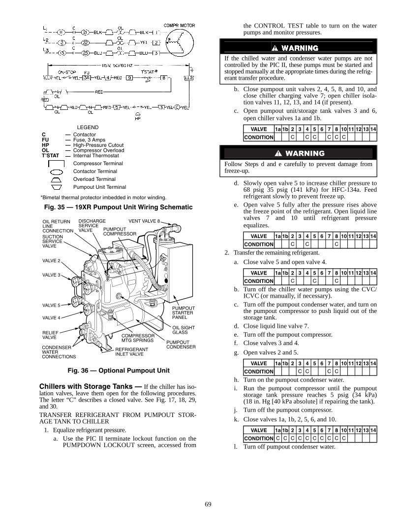
69
Chillers with Storage Tanks — If the chiller has iso-lation valves, leave them open for the following procedures.The letter “C” describes a closed valve. See Fig. 17, 18, 29,and 30.TRANSFER REFRIGERANT FROM PUMPOUT STOR-AGE TANK TO CHILLER
1. Equalize refrigerant pressure.a. Use the PIC II terminate lockout function on the
PUMPDOWN LOCKOUT screen, accessed from
the CONTROL TEST table to turn on the waterpumps and monitor pressures.
b. Close pumpout unit valves 2, 4, 5, 8, and 10, andclose chiller charging valve 7; open chiller isola-tion valves 11, 12, 13, and 14 (if present).
c. Open pumpout unit/storage tank valves 3 and 6,open chiller valves 1a and 1b.
d. Slowly open valve 5 to increase chiller pressure to68 psig 35 psig (141 kPa) for HFC-134a. Feedrefrigerant slowly to prevent freeze up.
e. Open valve 5 fully after the pressure rises abovethe freeze point of the refrigerant. Open liquid linevalves 7 and 10 until refrigerant pressureequalizes.
2. Transfer the remaining refrigerant.
a. Close valve 5 and open valve 4.
b. Turn off the chiller water pumps using the CVC/ICVC (or manually, if necessary).
c. Turn off the pumpout condenser water, and turn onthe pumpout compressor to push liquid out of thestorage tank.
d. Close liquid line valve 7.e. Turn off the pumpout compressor.f. Close valves 3 and 4.
g. Open valves 2 and 5.
h. Turn on the pumpout condenser water.i. Run the pumpout compressor until the pumpout
storage tank pressure reaches 5 psig (34 kPa)(18 in. Hg [40 kPa absolute] if repairing the tank).
j. Turn off the pumpout compressor.
k. Close valves 1a, 1b, 2, 5, 6, and 10.
l. Turn off pumpout condenser water.
If the chilled water and condenser water pumps are notcontrolled by the PIC II, these pumps must be started andstopped manually at the appropriate times during the refrig-erant transfer procedure.
VALVE 1a 1b 2 3 4 5 6 7 8 10 11 12 13 14
CONDITION C C C C C C
Follow Steps d and e carefully to prevent damage fromfreeze-up.
VALVE 1a 1b 2 3 4 5 6 7 8 10 11 12 13 14
CONDITION C C C
VALVE 1a 1b 2 3 4 5 6 7 8 10 11 12 13 14
CONDITION C C C
VALVE 1a 1b 2 3 4 5 6 7 8 10 11 12 13 14
CONDITION C C C C
VALVE 1a 1b 2 3 4 5 6 7 8 10 11 12 13 14
CONDITION C C C C C C C C C C
OIL RETURNLINECONNECTION
CONDENSERWATERCONNECTIONS
REFRIGERANTINLET VALVE
LEGEND
*Bimetal thermal protector imbedded in motor winding.
Fig. 35 — 19XR Pumpout Unit Wiring Schematic
C — ContactorFU — Fuse, 3 AmpsHP — High-Pressure CutoutOL — Compressor OverloadT’STAT — Internal Thermostat
Compressor Terminal
Contactor Terminal
Overload Terminal
Pumpout Unit Terminal
Fig. 36 — Optional Pumpout Unit
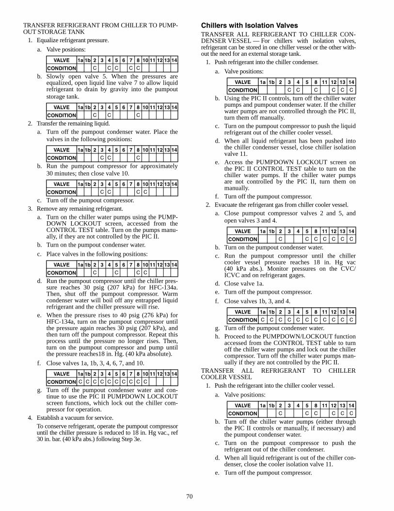
70
TRANSFER REFRIGERANT FROM CHILLER TO PUMP-OUT STORAGE TANK
1. Equalize refrigerant pressure.
a. Valve positions:
b. Slowly open valve 5. When the pressures areequalized, open liquid line valve 7 to allow liquidrefrigerant to drain by gravity into the pumpoutstorage tank.
2. Transfer the remaining liquid.a. Turn off the pumpout condenser water. Place the
valves in the following positions:
b. Run the pumpout compressor for approximately30 minutes; then close valve 10.
c. Turn off the pumpout compressor.3. Remove any remaining refrigerant.
a. Turn on the chiller water pumps using the PUMP-DOWN LOCKOUT screen, accessed from theCONTROL TEST table. Turn on the pumps manu-ally, if they are not controlled by the PIC II.
b. Turn on the pumpout condenser water.
c. Place valves in the following positions:
d. Run the pumpout compressor until the chiller pres-sure reaches 30 psig (207 kPa) for HFC-134a.Then, shut off the pumpout compressor. Warmcondenser water will boil off any entrapped liquidrefrigerant and the chiller pressure will rise.
e. When the pressure rises to 40 psig (276 kPa) forHFC-134a, turn on the pumpout compressor untilthe pressure again reaches 30 psig (207 kPa), andthen turn off the pumpout compressor. Repeat thisprocess until the pressure no longer rises. Then,turn on the pumpout compressor and pump untilthe pressure reaches18 in. Hg. (40 kPa absolute).
f. Close valves 1a, 1b, 3, 4, 6, 7, and 10.
g. Turn off the pumpout condenser water and con-tinue to use the PIC II PUMPDOWN LOCKOUTscreen functions, which lock out the chiller com-pressor for operation.
4. Establish a vacuum for service.To conserve refrigerant, operate the pumpout compressoruntil the chiller pressure is reduced to 18 in. Hg vac., ref30 in. bar. (40 kPa abs.) following Step 3e.
Chillers with Isolation ValvesTRANSFER ALL REFRIGERANT TO CHILLER CON-DENSER VESSEL — For chillers with isolation valves,refrigerant can be stored in one chiller vessel or the other with-out the need for an external storage tank.
1. Push refrigerant into the chiller condenser.
a. Valve positions:
b. Using the PIC II controls, turn off the chiller waterpumps and pumpout condenser water. If the chillerwater pumps are not controlled through the PIC II,turn them off manually.
c. Turn on the pumpout compressor to push the liquidrefrigerant out of the chiller cooler vessel.
d. When all liquid refrigerant has been pushed intothe chiller condenser vessel, close chiller isolationvalve 11.
e. Access the PUMPDOWN LOCKOUT screen onthe PIC II CONTROL TEST table to turn on thechiller water pumps. If the chiller water pumpsare not controlled by the PIC II, turn them onmanually.
f. Turn off the pumpout compressor.2. Evacuate the refrigerant gas from chiller cooler vessel.
a. Close pumpout compressor valves 2 and 5, andopen valves 3 and 4.
b. Turn on the pumpout condenser water.c. Run the pumpout compressor until the chiller
cooler vessel pressure reaches 18 in. Hg vac(40 kPa abs.). Monitor pressures on the CVC/ICVC and on refrigerant gages.
d. Close valve 1a.e. Turn off the pumpout compressor.
f. Close valves 1b, 3, and 4.
g. Turn off the pumpout condenser water.h. Proceed to the PUMPDOWN/LOCKOUT function
accessed from the CONTROL TEST table to turnoff the chiller water pumps and lock out the chillercompressor. Turn off the chiller water pumps man-ually if they are not controlled by the PIC II.
TRANSFER ALL REFRIGERANT TO CHILLERCOOLER VESSEL
1. Push the refrigerant into the chiller cooler vessel.
a. Valve positions:
b. Turn off the chiller water pumps (either throughthe PIC II controls or manually, if necessary) andthe pumpout condenser water.
c. Turn on the pumpout compressor to push therefrigerant out of the chiller condenser.
d. When all liquid refrigerant is out of the chiller con-denser, close the cooler isolation valve 11.
e. Turn off the pumpout compressor.
VALVE 1a 1b 2 3 4 5 6 7 8 10 11 12 13 14
CONDITION C C C C C
VALVE 1a 1b 2 3 4 5 6 7 8 10 11 12 13 14
CONDITION C C C
VALVE 1a 1b 2 3 4 5 6 7 8 10 11 12 13 14
CONDITION C C C
VALVE 1a 1b 2 3 4 5 6 7 8 10 11 12 13 14
CONDITION C C C C
VALVE 1a 1b 2 3 4 5 6 7 8 10 11 12 13 14
CONDITION C C C C
VALVE 1a 1b 2 3 4 5 6 7 8 10 11 12 13 14
CONDITION C C C C C C C C C C
VALVE 1a 1b 2 3 4 5 8 11 12 13 14
CONDITION C C C C C C
VALVE 1a 1b 2 3 4 5 8 11 12 13 14
CONDITION C C C C C C C
VALVE 1a 1b 2 3 4 5 8 11 12 13 14
CONDITION C C C C C C C C C C C
VALVE 1a 1b 2 3 4 5 8 11 12 13 14
CONDITION C C C C C C
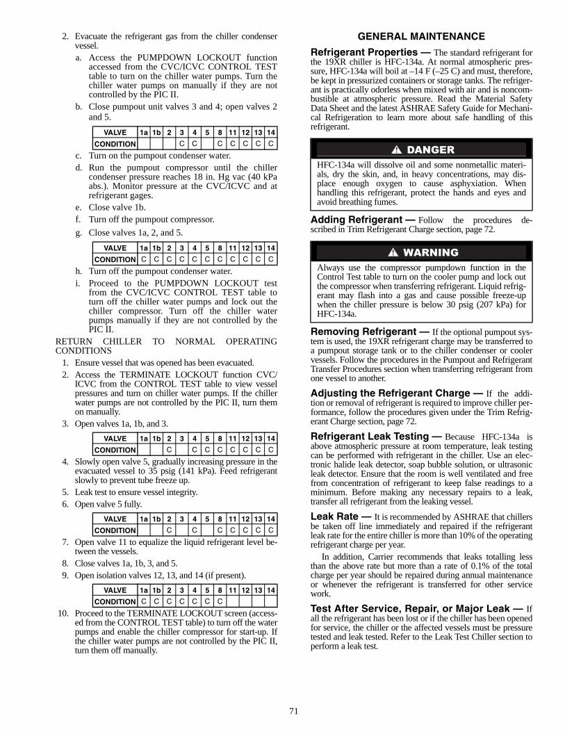
71
2. Evacuate the refrigerant gas from the chiller condenservessel.a. Access the PUMPDOWN LOCKOUT function
accessed from the CVC/ICVC CONTROL TESTtable to turn on the chiller water pumps. Turn thechiller water pumps on manually if they are notcontrolled by the PIC II.
b. Close pumpout unit valves 3 and 4; open valves 2and 5.
c. Turn on the pumpout condenser water.d. Run the pumpout compressor until the chiller
condenser pressure reaches 18 in. Hg vac (40 kPaabs.). Monitor pressure at the CVC/ICVC and atrefrigerant gages.
e. Close valve 1b.f. Turn off the pumpout compressor.
g. Close valves 1a, 2, and 5.
h. Turn off the pumpout condenser water.i. Proceed to the PUMPDOWN LOCKOUT test
from the CVC/ICVC CONTROL TEST table toturn off the chiller water pumps and lock out thechiller compressor. Turn off the chiller waterpumps manually if they are not controlled by thePIC II.
RETURN CHILLER TO NORMAL OPERATINGCONDITIONS
1. Ensure vessel that was opened has been evacuated.2. Access the TERMINATE LOCKOUT function CVC/
ICVC from the CONTROL TEST table to view vesselpressures and turn on chiller water pumps. If the chillerwater pumps are not controlled by the PIC II, turn themon manually.
3. Open valves 1a, 1b, and 3.
4. Slowly open valve 5, gradually increasing pressure in theevacuated vessel to 35 psig (141 kPa). Feed refrigerantslowly to prevent tube freeze up.
5. Leak test to ensure vessel integrity.6. Open valve 5 fully.
7. Open valve 11 to equalize the liquid refrigerant level be-tween the vessels.
8. Close valves 1a, 1b, 3, and 5.9. Open isolation valves 12, 13, and 14 (if present).
10. Proceed to the TERMINATE LOCKOUT screen (access-ed from the CONTROL TEST table) to turn off the waterpumps and enable the chiller compressor for start-up. Ifthe chiller water pumps are not controlled by the PIC II,turn them off manually.
GENERAL MAINTENANCE
Refrigerant Properties — The standard refrigerant forthe 19XR chiller is HFC-134a. At normal atmospheric pres-sure, HFC-134a will boil at –14 F (–25 C) and must, therefore,be kept in pressurized containers or storage tanks. The refriger-ant is practically odorless when mixed with air and is noncom-bustible at atmospheric pressure. Read the Material SafetyData Sheet and the latest ASHRAE Safety Guide for Mechani-cal Refrigeration to learn more about safe handling of thisrefrigerant.
Adding Refrigerant — Follow the procedures de-scribed in Trim Refrigerant Charge section, page 72.
Removing Refrigerant — If the optional pumpout sys-tem is used, the 19XR refrigerant charge may be transferred toa pumpout storage tank or to the chiller condenser or coolervessels. Follow the procedures in the Pumpout and RefrigerantTransfer Procedures section when transferring refrigerant fromone vessel to another.
Adjusting the Refrigerant Charge — If the addi-tion or removal of refrigerant is required to improve chiller per-formance, follow the procedures given under the Trim Refrig-erant Charge section, page 72.
Refrigerant Leak Testing — Because HFC-134a isabove atmospheric pressure at room temperature, leak testingcan be performed with refrigerant in the chiller. Use an elec-tronic halide leak detector, soap bubble solution, or ultrasonicleak detector. Ensure that the room is well ventilated and freefrom concentration of refrigerant to keep false readings to aminimum. Before making any necessary repairs to a leak,transfer all refrigerant from the leaking vessel.
Leak Rate — It is recommended by ASHRAE that chillersbe taken off line immediately and repaired if the refrigerantleak rate for the entire chiller is more than 10% of the operatingrefrigerant charge per year.
In addition, Carrier recommends that leaks totalling lessthan the above rate but more than a rate of 0.1% of the totalcharge per year should be repaired during annual maintenanceor whenever the refrigerant is transferred for other servicework.
Test After Service, Repair, or Major Leak — Ifall the refrigerant has been lost or if the chiller has been openedfor service, the chiller or the affected vessels must be pressuretested and leak tested. Refer to the Leak Test Chiller section toperform a leak test.
VALVE 1a 1b 2 3 4 5 8 11 12 13 14
CONDITION C C C C C C C
VALVE 1a 1b 2 3 4 5 8 11 12 13 14
CONDITION C C C C C C C C C C C
VALVE 1a 1b 2 3 4 5 8 11 12 13 14
CONDITION C C C C C C C C
VALVE 1a 1b 2 3 4 5 8 11 12 13 14
CONDITION C C C C C C C
VALVE 1a 1b 2 3 4 5 8 11 12 13 14
CONDITION C C C C C C C
HFC-134a will dissolve oil and some nonmetallic materi-als, dry the skin, and, in heavy concentrations, may dis-place enough oxygen to cause asphyxiation. Whenhandling this refrigerant, protect the hands and eyes andavoid breathing fumes.
Always use the compressor pumpdown function in theControl Test table to turn on the cooler pump and lock outthe compressor when transferring refrigerant. Liquid refrig-erant may flash into a gas and cause possible freeze-upwhen the chiller pressure is below 30 psig (207 kPa) forHFC-134a.
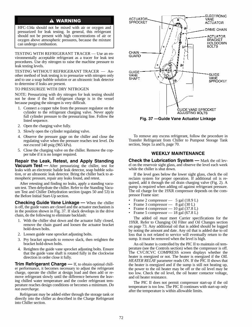
72
TESTING WITH REFRIGERANT TRACER — Use an en-vironmentally acceptable refrigerant as a tracer for leak testprocedures. Use dry nitrogen to raise the machine pressure toleak testing levels.TESTING WITHOUT REFRIGERANT TRACER — An-other method of leak testing is to pressurize with nitrogen onlyand to use a soap bubble solution or an ultrasonic leak detectorto determine if leaks are present.TO PRESSURIZE WITH DRY NITROGENNOTE: Pressurizing with dry nitrogen for leak testing shouldnot be done if the full refrigerant charge is in the vesselbecause purging the nitrogen is very difficult.
1. Connect a copper tube from the pressure regulator on thecylinder to the refrigerant charging valve. Never applyfull cylinder pressure to the pressurizing line. Follow thelisted sequence.
2. Open the charging valve fully.3. Slowly open the cylinder regulating valve.4. Observe the pressure gage on the chiller and close the
regulating valve when the pressure reaches test level. Donot exceed 140 psig (965 kPa).
5. Close the charging valve on the chiller. Remove the cop-per tube if it is no longer required.
Repair the Leak, Retest, and Apply StandingVacuum Test — After pressurizing the chiller, test forleaks with an electronic halide leak detector, soap bubble solu-tion, or an ultrasonic leak detector. Bring the chiller back to at-mospheric pressure, repair any leaks found, and retest.
After retesting and finding no leaks, apply a standing vacu-um test. Then dehydrate the chiller. Refer to the Standing Vacu-um Test and Chiller Dehydration section (pages 50 and 53) inthe Before Initial Start-Up section.
Checking Guide Vane Linkage — When the chilleris off, the guide vanes are closed and the actuator mechanism isin the position shown in Fig. 37. If slack develops in the drivechain, do the following to eliminate backlash:
1. With the chiller shut down and the actuator fully closed,remove the chain guard and loosen the actuator brackethold-down bolts.
2. Loosen guide vane sprocket adjusting bolts.3. Pry bracket upwards to remove slack, then retighten the
bracket hold-down bolts.4. Retighten the guide vane sprocket adjusting bolts. Ensure
that the guide vane shaft is rotated fully in the clockwisedirection in order close it fully.
Trim Refrigerant Charge — If, to obtain optimal chill-er performance, it becomes necessary to adjust the refrigerantcharge, operate the chiller at design load and then add or re-move refrigerant slowly until the difference between the leav-ing chilled water temperature and the cooler refrigerant tem-perature reaches design conditions or becomes a minimum. Donot overcharge.
Refrigerant may be added either through the storage tank ordirectly into the chiller as described in the Charge Refrigerantinto Chiller section.
To remove any excess refrigerant, follow the procedure inTransfer Refrigerant from Chiller to Pumpout Storage Tanksection, Steps 1a and b, page 70.
WEEKLY MAINTENANCE
Check the Lubrication System — Mark the oil lev-el on the reservoir sight glass, and observe the level each weekwhile the chiller is shut down.
If the level goes below the lower sight glass, check the oilreclaim system for proper operation. If additional oil is re-quired, add it through the oil drain charging valve (Fig. 2). Apump is required when adding oil against refrigerant pressure.The oil charge for the 19XR compressor depends on the com-pressor Frame size:• Frame 2 compressor — 5 gal (18.9 L)• Frame 3 compressor — 8 gal (30 L)• Frame 4 compressor — 10 gal (37.8 L)• Frame 5 compressor — 18 gal (67.8 L)
The added oil must meet Carrier specifications for the19XR. Refer to Changing Oil Filter and Oil Changes sectionon page 73. Any additional oil that is added should be loggedby noting the amount and date. Any oil that is added due to oilloss that is not related to service will eventually return to thesump. It must be removed when the level is high.
An oil heater is controlled by the PIC II to maintain oil tem-perature (see the Controls section) when the compressor is off.The CVC/ICVC COMPRESS screen displays whether theheater is energized or not. The heater is energized if the OILHEATER RELAY parameter reads ON. If the PIC II shows thatthe heater is energized and if the sump is still not heating up,the power to the oil heater may be off or the oil level may betoo low. Check the oil level, the oil heater contactor voltage,and oil heater resistance.
The PIC II does not permit compressor start-up if the oiltemperature is too low. The PIC II continues with start-up onlyafter the temperature is within allowable limits.
HFC-134a should not be mixed with air or oxygen andpressurized for leak testing. In general, this refrigerantshould not be present with high concentrations of air oroxygen above atmospheric pressures, because the mixturecan undergo combustion.
Fig. 37 —Guide Vane Actuator Linkage

73
SCHEDULED MAINTENANCE
Establish a regular maintenance schedule based on your ac-tual chiller requirements such as chiller load, run hours, andwater quality. The time intervals listed in this section areoffered as guides to service only.
Service Ontime — The CVC/ICVC will display a SER-VICE ONTIME value on the MAINSTAT screen. This valueshould be reset to zero by the service person or the operatoreach time major service work is completed so that the timebetween service can be viewed and tracked.
Inspect the Control Panel — Maintenance consists ofgeneral cleaning and tightening of connections. Vacuum thecabinet to eliminate dust build-up. If the chiller control mal-functions, refer to the Troubleshooting Guide section for con-trol checks and adjustments.
Check Safety and Operating Controls Monthly —To ensure chiller protection, the automated Control Testshould be performed at least once per month. See Table 3for safety control settings. See Table 9 for Control Testfunctions.
Changing Oil Filter — Change the oil filter on ayearly basis or when the chiller is opened for repairs. The19XR has an isolatable oil filter so that the filter may bechanged with the refrigerant remaining in the chiller. Usethe following procedure:
1. Ensure the compressor is off and the disconnect for thecompressor is open.
2. Disconnect the power to the oil pump.3. Close the oil filter isolation valves located behind power
panel on top of oil pump assembly.4. Connect an oil charging hose from the oil charging valve
(Fig. 2) and place the other end in a clean container suit-able for used oil. The oil drained from the filter housingshould be used as an oil sample and sent to a laboratoryfor proper analysis. Do not contaminate this sample.
5. Slowly open the charging valve to drain the oil from thehousing.
6. Once all oil has been drained, place some rags or absor-bent material under the oil filter housing to catch anydrips once the filter is opened. Remove the 4 bolts fromthe end of the filter housing and remove the filter cover.
7. Remove the filter retainer by unscrewing the retainer nut.The filter may now be removed and disposed of properly.
8. Replace the old filter with a new filter. Install the filter re-tainer and tighten down the retainer nut. Install the filtercover and tighten the 4 bolts.
9. Evacuate the filter housing by placing a vacuum pump onthe charging valve. Follow the normal evacuation proce-dures. Shut the charging valve when done and reconnectthe valve so that new oil can be pumped into the filterhousing. Fill with the same amount that was removed;then close the charging valve.
10. Remove the hose from the charging valve, open the isola-tion valves to the filter housing, and turn on the power tothe pump and the motor.
Oil Specification — If oil is added, it must meet the fol-lowing Carrier specifications:Oil Type for units using R-134a . . . . . . . . . . . . . . . . . . Inhibited
polyolester-based syntheticcompressor oil formatted for
use with HFC, gear-driven,hermetic compressors.
ISO Viscosity Grade . . . . . . . . . . . . . . . . . . . . . . . . . . . . . . . . 68The polyolester-based oil (P/N: PP23BZ103) may be
ordered from your local Carrier representative.
Oil Changes — Carrier recommends changing the oil af-ter the first year of operation and every five years thereafter asa minimum in addition to a yearly oil analysis. However, if acontinuous oil monitoring system is functioning and a yearlyoil analysis is performed, the time between oil changes can beextended.TO CHANGE THE OIL
1. Transfer the refrigerant into the chiller condenser vessel(for isolatable vessels) or to a pumpout storage tank.
2. Mark the existing oil level.3. Open the control and oil heater circuit breaker.4. When the chiller pressure is 5 psig (34 kPa) or less, drain
the oil reservoir by opening the oil charging valve(Fig. 2). Slowly open the valve against refrigerantpressure.
5. Change the oil filter at this time. See Changing Oil Filtersection.
6. Change the refrigerant filter at this time, see the next sec-tion, Refrigerant Filter.
7. Charge the chiller with oil. Charge until the oil level isequal to the oil level marked in Step 2. Turn on the powerto the oil heater and let the PIC II warm it up to at least140 F (60 C). Operate the oil pump manually, using theControl Test function, for 2 minutes. For shutdown condi-tions, the oil level should be full in the lower sight glass.If the oil level is above 1/2 full in the upper sight glass, re-move the excess oil. The oil level should now be equal tothe amount shown in Step 2.
Refrigerant Filter — A refrigerant filter/drier, located onthe refrigerant cooling line to the motor, should be changedonce a year or more often if filter condition indicates a need formore frequent replacement. Change the filter by closing the fil-ter isolation valves (Fig. 4) and slowly opening the flare fittingswith a wrench and back-up wrench to relieve the pressure. Amoisture indicator sight glass is located beyond this filter to in-dicate the volume and moisture in the refrigerant. If the mois-ture indicator indicates moisture, locate the source of water im-mediately by performing a thorough leak check.
Oil Reclaim Filter — The oil reclaim system has astrainer on the eductor suction line, a strainer on the dischargepressure line, and a filter on the cooler scavenging line.Replace the filter once per year or more often if filter conditionindicates a need for more frequent replacement. Change the fil-ter by closing the filter isolation valves and slowly opening theflare fitting with a wrench and back-up wrench to relieve thepressure. Change the strainers once every 5 years or wheneverrefrigerant is evacuated from the cooler.
Ensure power to the control center is off when cleaning andtightening connections inside the control panel.
The oil filter housing is at a high pressure. Relieve thispressure slowly.
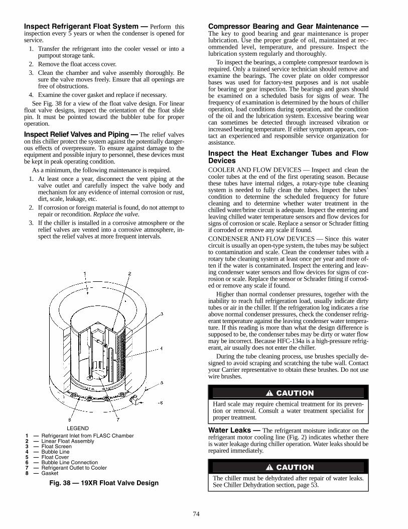
74
Inspect Refrigerant Float System — Perform thisinspection every 5 years or when the condenser is opened forservice.
1. Transfer the refrigerant into the cooler vessel or into apumpout storage tank.
2. Remove the float access cover.3. Clean the chamber and valve assembly thoroughly. Be
sure the valve moves freely. Ensure that all openings arefree of obstructions.
4. Examine the cover gasket and replace if necessary.See Fig. 38 for a view of the float valve design. For linear
float valve designs, inspect the orientation of the float slidepin. It must be pointed toward the bubbler tube for properoperation.
Inspect Relief Valves and Piping — The relief valveson this chiller protect the system against the potentially danger-ous effects of overpressure. To ensure against damage to theequipment and possible injury to personnel, these devices mustbe kept in peak operating condition.
As a minimum, the following maintenance is required.1. At least once a year, disconnect the vent piping at the
valve outlet and carefully inspect the valve body andmechanism for any evidence of internal corrosion or rust,dirt, scale, leakage, etc.
2. If corrosion or foreign material is found, do not attempt torepair or recondition. Replace the valve.
3. If the chiller is installed in a corrosive atmosphere or therelief valves are vented into a corrosive atmosphere, in-spect the relief valves at more frequent intervals.
Compressor Bearing and Gear Maintenance —The key to good bearing and gear maintenance is properlubrication. Use the proper grade of oil, maintained at rec-ommended level, temperature, and pressure. Inspect thelubrication system regularly and thoroughly.
To inspect the bearings, a complete compressor teardown isrequired. Only a trained service technician should remove andexamine the bearings. The cover plate on older compressorbases was used for factory-test purposes and is not usablefor bearing or gear inspection. The bearings and gears shouldbe examined on a scheduled basis for signs of wear. Thefrequency of examination is determined by the hours of chilleroperation, load conditions during operation, and the conditionof the oil and the lubrication system. Excessive bearing wearcan sometimes be detected through increased vibration orincreased bearing temperature. If either symptom appears, con-tact an experienced and responsible service organization forassistance.
Inspect the Heat Exchanger Tubes and FlowDevicesCOOLER AND FLOW DEVICES — Inspect and clean thecooler tubes at the end of the first operating season. Becausethese tubes have internal ridges, a rotary-type tube cleaningsystem is needed to fully clean the tubes. Inspect the tubes’condition to determine the scheduled frequency for futurecleaning and to determine whether water treatment in thechilled water/brine circuit is adequate. Inspect the entering andleaving chilled water temperature sensors and flow devices forsigns of corrosion or scale. Replace a sensor or Schrader fittingif corroded or remove any scale if found.CONDENSER AND FLOW DEVICES — Since this watercircuit is usually an open-type system, the tubes may be subjectto contamination and scale. Clean the condenser tubes with arotary tube cleaning system at least once per year and more of-ten if the water is contaminated. Inspect the entering and leav-ing condenser water sensors and flow devices for signs of cor-rosion or scale. Replace the sensor or Schrader fitting if corrod-ed or remove any scale if found.
Higher than normal condenser pressures, together with theinability to reach full refrigeration load, usually indicate dirtytubes or air in the chiller. If the refrigeration log indicates a riseabove normal condenser pressures, check the condenser refrig-erant temperature against the leaving condenser water tempera-ture. If this reading is more than what the design difference issupposed to be, the condenser tubes may be dirty or water flowmay be incorrect. Because HFC-134a is a high-pressure refrig-erant, air usually does not enter the chiller.
During the tube cleaning process, use brushes specially de-signed to avoid scraping and scratching the tube wall. Contactyour Carrier representative to obtain these brushes. Do not usewire brushes.
Water Leaks — The refrigerant moisture indicator on therefrigerant motor cooling line (Fig. 2) indicates whether thereis water leakage during chiller operation. Water leaks should berepaired immediately.
Hard scale may require chemical treatment for its preven-tion or removal. Consult a water treatment specialist forproper treatment.
The chiller must be dehydrated after repair of water leaks.See Chiller Dehydration section, page 53.
LEGEND
Fig. 38 — 19XR Float Valve Design
1 — Refrigerant Inlet from FLASC Chamber2 — Linear Float Assembly3 — Float Screen4 — Bubble Line5 — Float Cover6 — Bubble Line Connection7 — Refrigerant Outlet to Cooler8 — Gasket
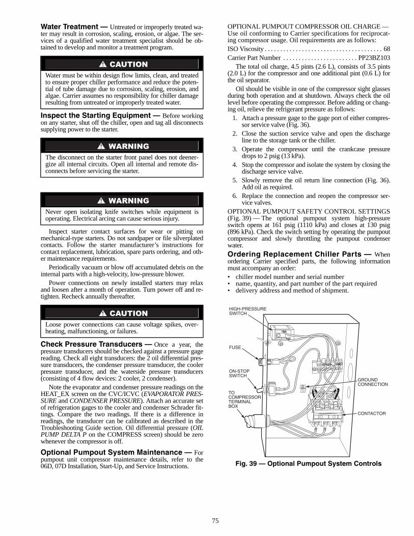
75
Water Treatment — Untreated or improperly treated wa-ter may result in corrosion, scaling, erosion, or algae. The ser-vices of a qualified water treatment specialist should be ob-tained to develop and monitor a treatment program.
Inspect the Starting Equipment — Before workingon any starter, shut off the chiller, open and tag all disconnectssupplying power to the starter.
Inspect starter contact surfaces for wear or pitting onmechanical-type starters. Do not sandpaper or file silverplatedcontacts. Follow the starter manufacturer’s instructions forcontact replacement, lubrication, spare parts ordering, and oth-er maintenance requirements.
Periodically vacuum or blow off accumulated debris on theinternal parts with a high-velocity, low-pressure blower.
Power connections on newly installed starters may relaxand loosen after a month of operation. Turn power off and re-tighten. Recheck annually thereafter.
Check Pressure Transducers — Once a year, thepressure transducers should be checked against a pressure gagereading. Check all eight transducers: the 2 oil differential pres-sure transducers, the condenser pressure transducer, the coolerpressure transducer, and the waterside pressure transducers(consisting of 4 flow devices: 2 cooler, 2 condenser).
Note the evaporator and condenser pressure readings on theHEAT_EX screen on the CVC/ICVC (EVAPORATOR PRES-SURE and CONDENSER PRESSURE). Attach an accurate setof refrigeration gages to the cooler and condenser Schrader fit-tings. Compare the two readings. If there is a difference inreadings, the transducer can be calibrated as described in theTroubleshooting Guide section. Oil differential pressure (OILPUMP DELTA P on the COMPRESS screen) should be zerowhenever the compressor is off.
Optional Pumpout System Maintenance — Forpumpout unit compressor maintenance details, refer to the06D, 07D Installation, Start-Up, and Service Instructions.
OPTIONAL PUMPOUT COMPRESSOR OIL CHARGE — Use oil conforming to Carrier specifications for reciprocat-ing compressor usage. Oil requirements are as follows:ISO Viscosity . . . . . . . . . . . . . . . . . . . . . . . . . . . . . . . . . . . . . . 68Carrier Part Number . . . . . . . . . . . . . . . . . . . . . . . . PP23BZ103
The total oil charge, 4.5 pints (2.6 L), consists of 3.5 pints(2.0 L) for the compressor and one additional pint (0.6 L) forthe oil separator.
Oil should be visible in one of the compressor sight glassesduring both operation and at shutdown. Always check the oillevel before operating the compressor. Before adding or chang-ing oil, relieve the refrigerant pressure as follows:
1. Attach a pressure gage to the gage port of either compres-sor service valve (Fig. 36).
2. Close the suction service valve and open the dischargeline to the storage tank or the chiller.
3. Operate the compressor until the crankcase pressuredrops to 2 psig (13 kPa).
4. Stop the compressor and isolate the system by closing thedischarge service valve.
5. Slowly remove the oil return line connection (Fig. 36).Add oil as required.
6. Replace the connection and reopen the compressor ser-vice valves.
OPTIONAL PUMPOUT SAFETY CONTROL SETTINGS(Fig. 39) — The optional pumpout system high-pressureswitch opens at 161 psig (1110 kPa) and closes at 130 psig(896 kPa). Check the switch setting by operating the pumpoutcompressor and slowly throttling the pumpout condenserwater.Ordering Replacement Chiller Parts — Whenordering Carrier specified parts, the following informationmust accompany an order:• chiller model number and serial number• name, quantity, and part number of the part required• delivery address and method of shipment.
Water must be within design flow limits, clean, and treatedto ensure proper chiller performance and reduce the poten-tial of tube damage due to corrosion, scaling, erosion, andalgae. Carrier assumes no responsibility for chiller damageresulting from untreated or improperly treated water.
The disconnect on the starter front panel does not deener-gize all internal circuits. Open all internal and remote dis-connects before servicing the starter.
Never open isolating knife switches while equipment isoperating. Electrical arcing can cause serious injury.
Loose power connections can cause voltage spikes, over-heating, malfunctioning, or failures.
Fig. 39 — Optional Pumpout System Controls
76
TROUBLESHOOTING GUIDE
Overview — The PIC II has many features to help the op-erator and technician troubleshoot a 19XR chiller.• The CVC/ICVC shows the chiller’s actual operating con-
ditions and can be viewed while the unit is running.• The CVC/ICVC default screen freezes when an alarm
occurs. The freeze enables the operator to view thechiller conditions at the time of alarm. The STATUSscreens continue to show current information. Once allalarms have been cleared (by correcting the problemsand pressing the softkey), the CVC/ICVCdefault screen returns to normal operation.
• The CONTROL ALGORITHM STATUS screens (whichinclude the CAPACITY, OVERRIDE, LL_MAINT,ISM_HIST, LOADSHED, WSMDEFME, andOCCDEFCM screens) display information that helps todiagnose problems with chilled water temperaturecontrol, chilled water temperature control overrides, hotgas bypass, surge algorithm status, and time scheduleoperation.
• The control test feature facilitates the proper operationand test of temperature sensors, pressure transducers, theguide vane actuator, oil pump, water pumps, tower con-trol, and other on/off outputs while the compressor isstopped. It also has the ability to lock off the compressorand turn on water pumps for pumpout operation. TheCVC/ICVC shows the temperatures and pressuresrequired during these operations.
• From other SERVICE tables, the operator/technician canaccess configured items, such as chilled water resets,override set points, etc.
• If an operating fault is detected, an alarm message is gen-erated and displayed on the CVC/ICVC default screen.A more detailed message — along with a diagnosticmessage — is also stored into the ALARM HISTORYtable.
Checking Display Messages — The first area tocheck when troubleshooting the 19XR is the CVC/ICVC dis-play. If the alarm light is flashing, check the primary and sec-ondary message lines on the CVC/ICVC default screen(Fig. 14). These messages will indicate where the fault is oc-curring. These messages contain the alarm message with aspecified code. This code or state appears with each alarm andalert message. The ALARM HISTORY table on the CVC/ICVC SERVICE menu also contains an alarm message to fur-ther expand on the alarm. For a complete list of possible alarmmessages, see Table 11. If the alarm light starts to flash whileaccessing a menu screen, press the softkey to return tothe default screen to read the alarm message. The STATUSscreen can also be accessed to determine where an alarm exists.
Checking Temperature Sensors — All temperaturesensors are thermistor-type sensors. This means that the resis-tance of the sensor varies with temperature. All sensors havethe same resistance characteristics. If the controls are on, deter-mine sensor temperature by measuring voltage drop; if the con-trols are powered off, determine sensor temperature by measur-ing resistance. Compare the readings to the values listed inTable 12A or 12B.RESISTANCE CHECK — Turn off the control power and,from the module, disconnect the terminal plug of the sensor inquestion. With a digital ohmmeter, measure sensor resistancebetween receptacles as designated by the wiring diagram. Theresistance and corresponding temperature are listed inTable 12A or 12B. Check the resistance of both wires toground. This resistance should be infinite.
VOLTAGE DROP — The voltage drop across any energizedsensor can be measured with a digital voltmeter while the con-trol is energized. Table 12A or 12B lists the relationship be-tween temperature and sensor voltage drop (volts dc measuredacross the energized sensor). Exercise care when measuringvoltage to prevent damage to the sensor leads, connector plugs,and modules. Sensors should also be checked at the sensorplugs. Check the sensor wire at the sensor for 5 vdc if the con-trol is powered on.
CHECK SENSOR ACCURACY — Place the sensor in amedium of known temperature and compare that temperatureto the measured reading. The thermometer used to determinethe temperature of the medium should be of laboratory qualitywith 0.5° F (.25° C) graduations. The sensor in question shouldbe accurate to within 2° F (1.2° C).
See Fig. 9 for sensor locations. The sensors are immerseddirectly in the refrigerant or water circuits. The wiring at eachsensor is easily disconnected by unlatching the connector.These connectors allow only one-way connection to the sensor.When installing a new sensor, apply a pipe sealant or threadsealant to the sensor threads.DUAL TEMPERATURE SENSORS — For servicing con-venience, there are 2 sensors each on the bearing and motortemperature sensors. If one of the sensors is damaged, the othercan be used by simply moving a wire. The number 2 terminalin the sensor terminal box is the common line. To use the sec-ond sensor, move the wire from the number 1 position to thenumber 3 position.
Checking Pressure TransducersUNITS EQUIPPED WITH CVC — There are 8 pressuretransducers on 19XR chillers. They determine cooler, condens-er, oil pressure, and cooler and condenser flow. The cooler andcondenser transducers are also used by the PIC II to determinethe refrigerant temperatures. The oil supply pressure transducervalue and the oil transmission sump pressure transducer valuedifference is calculated by the CCM. The CVC module thendisplays the differential pressure. In effect, the CVC reads onlyone input for oil pressure for a total of 5 pressure inputs: coolerpressure, condenser pressure, oil differential pressure, coolerwaterside differential pressure, and condenser waterside differ-ential pressure. See the Check Pressure Transducers section(page 75) under Scheduled Maintenance.UNITS EQUIPPED WITH ICVC — There are 6 factory-installed pressure transducers, with inputs available for bothcooler and The ICVC software will display a default reading of26 psi during start-up and operation. An additional transducer,factory installed in the bottom of the cooler barrel, will read asEVAPORATOR SACTURATION TEMP on the HEAT_EXDISPLAY screen. This provides additional protection against aloss of water flow condition.
These pressure transducers can be calibrated if necessary. Itis not usually necessary to calibrate at initial start-up.However, at high altitude locations, it is necessary to calibratethe transducers to ensure the proper refrigerant temperature/pressure relationship. Each transducer is supplied with 5 vdcpower from the CCM. If the power supply fails, a transducervoltage reference alarm occurs. If the transducer reading issuspected of being faulty, check the supply voltage. It shouldbe 5 vdc ±.5 v displayed in CONTROL TEST under CCMPressure Transducers. If the supply voltage is correct, the trans-ducer should be recalibrated or replaced.
RESET
EXIT
Relieve all refrigerant pressure or drain the water beforereplacing the temperature sensors.
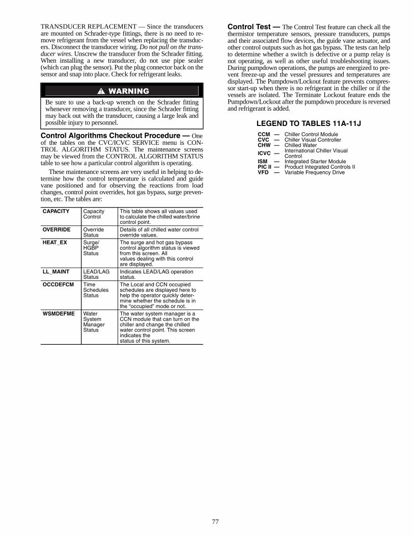
77
TRANSDUCER REPLACEMENT — Since the transducersare mounted on Schrader-type fittings, there is no need to re-move refrigerant from the vessel when replacing the transduc-ers. Disconnect the transducer wiring. Do not pull on the trans-ducer wires. Unscrew the transducer from the Schrader fitting.When installing a new transducer, do not use pipe sealer(which can plug the sensor). Put the plug connector back on thesensor and snap into place. Check for refrigerant leaks.
Control Algorithms Checkout Procedure — Oneof the tables on the CVC/ICVC SERVICE menu is CON-TROL ALGORITHM STATUS. The maintenance screensmay be viewed from the CONTROL ALGORITHM STATUStable to see how a particular control algorithm is operating.
These maintenance screens are very useful in helping to de-termine how the control temperature is calculated and guidevane positioned and for observing the reactions from loadchanges, control point overrides, hot gas bypass, surge preven-tion, etc. The tables are:
Control Test — The Control Test feature can check all thethermistor temperature sensors, pressure transducers, pumpsand their associated flow devices, the guide vane actuator, andother control outputs such as hot gas bypass. The tests can helpto determine whether a switch is defective or a pump relay isnot operating, as well as other useful troubleshooting issues.During pumpdown operations, the pumps are energized to pre-vent freeze-up and the vessel pressures and temperatures aredisplayed. The Pumpdown/Lockout feature prevents compres-sor start-up when there is no refrigerant in the chiller or if thevessels are isolated. The Terminate Lockout feature ends thePumpdown/Lockout after the pumpdown procedure is reversedand refrigerant is added.
LEGEND TO TABLES 11A-11J
Be sure to use a back-up wrench on the Schrader fittingwhenever removing a transducer, since the Schrader fittingmay back out with the transducer, causing a large leak andpossible injury to personnel.
CAPACITY CapacityControl
This table shows all values used to calculate the chilled water/brine control point.
OVERRIDE OverrideStatus
Details of all chilled water control override values.
HEAT_EX Surge/HGBPStatus
The surge and hot gas bypass control algorithm status is viewed from this screen. Allvalues dealing with this control are displayed.
LL_MAINT LEAD/LAGStatus
Indicates LEAD/LAG operation status.
OCCDEFCM TimeSchedulesStatus
The Local and CCN occupied schedules are displayed here to help the operator quickly deter-mine whether the schedule is in the “occupied” mode or not.
WSMDEFME WaterSystemManagerStatus
The water system manager is a CCN module that can turn on the chiller and change the chilled water control point. This screen indicates thestatus of this system.
CCM — Chiller Control ModuleCVC — Chiller Visual ControllerCHW — Chilled Water
ICVC — International Chiller Visual Control
ISM — Integrated Starter ModulePIC II — Product Integrated Controls IIVFD — Variable Frequency Drive
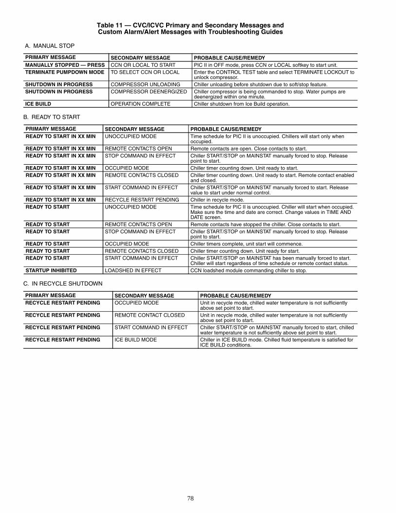
78
Table 11 — CVC/ICVC Primary and Secondary Messages andCustom Alarm/Alert Messages with Troubleshooting Guides
A. MANUAL STOP
B. READY TO START
C. IN RECYCLE SHUTDOWN
PRIMARY MESSAGE SECONDARY MESSAGE PROBABLE CAUSE/REMEDYMANUALLY STOPPED — PRESS CCN OR LOCAL TO START PIC II in OFF mode, press CCN or LOCAL softkey to start unit.TERMINATE PUMPDOWN MODE TO SELECT CCN OR LOCAL Enter the CONTROL TEST table and select TERMINATE LOCKOUT to
unlock compressor.SHUTDOWN IN PROGRESS COMPRESSOR UNLOADING Chiller unloading before shutdown due to soft/stop feature.SHUTDOWN IN PROGRESS COMPRESSOR DEENERGIZED Chiller compressor is being commanded to stop. Water pumps are
deenergized within one minute.ICE BUILD OPERATION COMPLETE Chiller shutdown from Ice Build operation.
PRIMARY MESSAGE SECONDARY MESSAGE PROBABLE CAUSE/REMEDYREADY TO START IN XX MIN UNOCCUPIED MODE Time schedule for PIC II is unoccupied. Chillers will start only when
occupied.READY TO START IN XX MIN REMOTE CONTACTS OPEN Remote contacts are open. Close contacts to start.READY TO START IN XX MIN STOP COMMAND IN EFFECT Chiller START/STOP on MAINSTAT manually forced to stop. Release
point to start.READY TO START IN XX MIN OCCUPIED MODE Chiller timer counting down. Unit ready to start.READY TO START IN XX MIN REMOTE CONTACTS CLOSED Chiller timer counting down. Unit ready to start. Remote contact enabled
and closed.READY TO START IN XX MIN START COMMAND IN EFFECT Chiller START/STOP on MAINSTAT manually forced to start. Release
value to start under normal control.READY TO START IN XX MIN RECYCLE RESTART PENDING Chiller in recycle mode.READY TO START UNOCCUPIED MODE Time schedule for PIC II is unoccupied. Chiller will start when occupied.
Make sure the time and date are correct. Change values in TIME AND DATE screen.
READY TO START REMOTE CONTACTS OPEN Remote contacts have stopped the chiller. Close contacts to start.READY TO START STOP COMMAND IN EFFECT Chiller START/STOP on MAINSTAT manually forced to stop. Release
point to start.READY TO START OCCUPIED MODE Chiller timers complete, unit start will commence.READY TO START REMOTE CONTACTS CLOSED Chiller timer counting down. Unit ready for start.READY TO START START COMMAND IN EFFECT Chiller START/STOP on MAINSTAT has been manually forced to start.
Chiller will start regardless of time schedule or remote contact status.STARTUP INHIBITED LOADSHED IN EFFECT CCN loadshed module commanding chiller to stop.
PRIMARY MESSAGE SECONDARY MESSAGE PROBABLE CAUSE/REMEDYRECYCLE RESTART PENDING OCCUPIED MODE Unit in recycle mode, chilled water temperature is not sufficiently
above set point to start.RECYCLE RESTART PENDING REMOTE CONTACT CLOSED Unit in recycle mode, chilled water temperature is not sufficiently
above set point to start.RECYCLE RESTART PENDING START COMMAND IN EFFECT Chiller START/STOP on MAINSTAT manually forced to start, chilled
water temperature is not sufficiently above set point to start.RECYCLE RESTART PENDING ICE BUILD MODE Chiller in ICE BUILD mode. Chilled fluid temperature is satisfied for
ICE BUILD conditions.
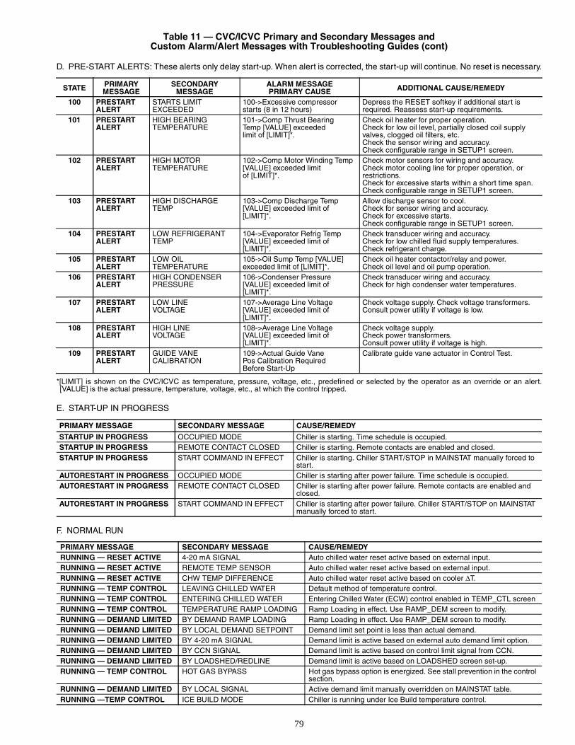
79
Table 11 — CVC/ICVC Primary and Secondary Messages andCustom Alarm/Alert Messages with Troubleshooting Guides (cont)
D. PRE-START ALERTS: These alerts only delay start-up. When alert is corrected, the start-up will continue. No reset is necessary.
*[LIMIT] is shown on the CVC/ICVC as temperature, pressure, voltage, etc., predefined or selected by the operator as an override or an alert.[VALUE] is the actual pressure, temperature, voltage, etc., at which the control tripped.
E. START-UP IN PROGRESS
F. NORMAL RUN
STATE PRIMARYMESSAGE
SECONDARYMESSAGE
ALARM MESSAGEPRIMARY CAUSE ADDITIONAL CAUSE/REMEDY
100 PRESTARTALERT
STARTS LIMITEXCEEDED
100->Excessive compressor starts (8 in 12 hours)
Depress the RESET softkey if additional start is required. Reassess start-up requirements.
101 PRESTARTALERT
HIGH BEARINGTEMPERATURE
101->Comp Thrust BearingTemp [VALUE] exceededlimit of [LIMIT]*.
Check oil heater for proper operation.Check for low oil level, partially closed coil supplyvalves, clogged oil filters, etc.Check the sensor wiring and accuracy.Check configurable range in SETUP1 screen.
102 PRESTARTALERT
HIGH MOTORTEMPERATURE
102->Comp Motor Winding Temp [VALUE] exceeded limitof [LIMIT]*.
Check motor sensors for wiring and accuracy.Check motor cooling line for proper operation, orrestrictions.Check for excessive starts within a short time span.Check configurable range in SETUP1 screen.
103 PRESTARTALERT
HIGH DISCHARGETEMP
103->Comp Discharge Temp [VALUE] exceeded limit of [LIMIT]*.
Allow discharge sensor to cool.Check for sensor wiring and accuracy.Check for excessive starts.Check configurable range in SETUP1 screen.
104 PRESTARTALERT
LOW REFRIGERANTTEMP
104->Evaporator Refrig Temp [VALUE] exceeded limit of [LIMIT]*.
Check transducer wiring and accuracy.Check for low chilled fluid supply temperatures.Check refrigerant charge.
105 PRESTARTALERT
LOW OILTEMPERATURE
105->Oil Sump Temp [VALUE] exceeded limit of [LIMIT]*.
Check oil heater contactor/relay and power.Check oil level and oil pump operation.
106 PRESTARTALERT
HIGH CONDENSERPRESSURE
106->Condenser Pressure [VALUE] exceeded limit of [LIMIT]*.
Check transducer wiring and accuracy.Check for high condenser water temperatures.
107 PRESTARTALERT
LOW LINEVOLTAGE
107->Average Line Voltage [VALUE] exceeded limit of [LIMIT]*.
Check voltage supply. Check voltage transformers.Consult power utility if voltage is low.
108 PRESTARTALERT
HIGH LINEVOLTAGE
108->Average Line Voltage [VALUE] exceeded limit of [LIMIT]*.
Check voltage supply.Check power transformers.Consult power utility if voltage is high.
109 PRESTARTALERT
GUIDE VANECALIBRATION
109->Actual Guide VanePos Calibration RequiredBefore Start-Up
Calibrate guide vane actuator in Control Test.
PRIMARY MESSAGE SECONDARY MESSAGE CAUSE/REMEDY
STARTUP IN PROGRESS OCCUPIED MODE Chiller is starting. Time schedule is occupied.STARTUP IN PROGRESS REMOTE CONTACT CLOSED Chiller is starting. Remote contacts are enabled and closed.STARTUP IN PROGRESS START COMMAND IN EFFECT Chiller is starting. Chiller START/STOP in MAINSTAT manually forced to
start.AUTORESTART IN PROGRESS OCCUPIED MODE Chiller is starting after power failure. Time schedule is occupied.AUTORESTART IN PROGRESS REMOTE CONTACT CLOSED Chiller is starting after power failure. Remote contacts are enabled and
closed.AUTORESTART IN PROGRESS START COMMAND IN EFFECT Chiller is starting after power failure. Chiller START/STOP on MAINSTAT
manually forced to start.
PRIMARY MESSAGE SECONDARY MESSAGE CAUSE/REMEDYRUNNING — RESET ACTIVE 4-20 mA SIGNAL Auto chilled water reset active based on external input.RUNNING — RESET ACTIVE REMOTE TEMP SENSOR Auto chilled water reset active based on external input.RUNNING — RESET ACTIVE CHW TEMP DIFFERENCE Auto chilled water reset active based on cooler ∆T.RUNNING — TEMP CONTROL LEAVING CHILLED WATER Default method of temperature control.RUNNING — TEMP CONTROL ENTERING CHILLED WATER Entering Chilled Water (ECW) control enabled in TEMP_CTL screenRUNNING — TEMP CONTROL TEMPERATURE RAMP LOADING Ramp Loading in effect. Use RAMP_DEM screen to modify.RUNNING — DEMAND LIMITED BY DEMAND RAMP LOADING Ramp Loading in effect. Use RAMP_DEM screen to modify.RUNNING — DEMAND LIMITED BY LOCAL DEMAND SETPOINT Demand limit set point is less than actual demand.RUNNING — DEMAND LIMITED BY 4-20 mA SIGNAL Demand limit is active based on external auto demand limit option.RUNNING — DEMAND LIMITED BY CCN SIGNAL Demand limit is active based on control limit signal from CCN.RUNNING — DEMAND LIMITED BY LOADSHED/REDLINE Demand limit is active based on LOADSHED screen set-up.RUNNING — TEMP CONTROL HOT GAS BYPASS Hot gas bypass option is energized. See stall prevention in the control
section.RUNNING — DEMAND LIMITED BY LOCAL SIGNAL Active demand limit manually overridden on MAINSTAT table.RUNNING —TEMP CONTROL ICE BUILD MODE Chiller is running under Ice Build temperature control.
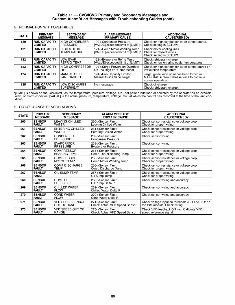
80
Table 11 — CVC/ICVC Primary and Secondary Messages andCustom Alarm/Alert Messages with Troubleshooting Guides (cont)
G. NORMAL RUN WITH OVERRIDES
*[LIMIT] is shown on the CVC/ICVC as the temperature, pressure, voltage, etc., set point predefined or selected by the operator as an override,alert, or alarm condition. [VALUE] is the actual pressure, temperature, voltage, etc., at which the control has recorded at the time of the fault con-dition.
H. OUT-OF-RANGE SENSOR ALARMS
STATE PRIMARYMESSAGE
SECONDARYMESSAGE
ALARM MESSAGEPRIMARY CAUSE
ADDITIONALCAUSE/REMEDY
120 RUN CAPACITYLIMITED
HIGH CONDENSERPRESSURE
120->Condenser Pressure [VALUE] exceeded limit of [LIMIT]*.
Check for high condenser water temperatures.Check setting in SETUP1.
121 RUN CAPACITYLIMITED
HIGH MOTORTEMPERATURE
121->Comp Motor Winding Temp [VALUE] exceeded limit of [LIMIT]*.
Check motor cooling lines.Check for closed valves.Check setting in SETUP1.
122 RUN CAPACITYLIMITED
LOW EVAPREFRIG TEMP
122->Evaporator Refrig Temp [VALUE] exceeded limit of [LIMIT]*.
Check refrigerant charge.Check for low entering cooler temperatures.
123 RUN CAPACITYLIMITED
HIGH COMPRESSORLIFT
123->Surge Prevention Override:Lift Too High For Compressor.
Check for high condenser water temperatures or low suction temperature.
124 RUN CAPACITYLIMITED
MANUAL GUIDEVANE TARGET
124->Run Capacity Limited:Manual Guide Vane Target.
Target guide vane point has been forced inMAINSTAT screen. Release force to continue normal operation.
125 RUN CAPACITYLIMITED
LOW DISCHARGESUPERHEAT
No messages. Check oil charge.Check refrigerant charge.
STATE PRIMARYMESSAGE
SECONDARYMESSAGE
ALARM MESSAGEPRIMARY CAUSE
ADDITIONALCAUSE/REMEDY
260 SENSORFAULT
LEAVING CHILLEDWATER
260->Sensor Fault:Leaving Chilled Water
Check sensor resistance or voltage drop.Check for proper wiring.
261 SENSORFAULT
ENTERING CHILLEDWATER
261->Sensor Fault:Entering Chilled Water
Check sensor resistance or voltage drop.Check for proper wiring.
262 SENSORFAULT
CONDENSERPRESSURE
262->Sensor Fault:Condenser Pressure
Check sensor wiring.
263 SENSORFAULT
EVAPORATORPRESSURE
263->Sensor Fault:Evaporator Pressure
Check sensor wiring.
264 SENSORFAULT
COMPRESSORBEARING TEMP
264->Sensor Fault:Comp Thrust Bearing Temp
Check sensor resistance or voltage drop.Check for proper wiring.
265 SENSORFAULT
COMPRESSORMOTOR TEMP
265->Sensor Fault:Comp Motor Winding Temp
Check sensor resistance or voltage drop.Check for proper wiring.
266 SENSORFAULT
COMP DISCHARGETEMP
266->Sensor Fault:Comp Discharge Temp
Check sensor resistance or voltage drop.Check for proper wiring.
267 SENSORFAULT
OIL SUMP TEMP 267->Sensor Fault:Oil Sump Temp
Check sensor resistance or voltage drop.Check for proper wiring.
268 SENSORFAULT
COMP OILPRESS DIFF
268->Sensor Fault:Oil Pump Delta P
Check sensor wiring and accuracy.
269 SENSORFAULT
CHILLED WATERFLOW
269->Sensor Fault:Chilled Water Delta P
Check sensor wiring and accuracy.
270 SENSORFAULT
COND WATERFLOW
270->Sensor Fault:Cond Water Delta P
Check sensor wiring and accuracy.
271 SENSORFAULT
VFD SPEED SENSOR OUT OF RANGE
271->Sensor Fault:Check Actual VFD Speed Sensor
Check voltage input on terminals J6-1 and J6-2 on the ISM module. Check wiring.
273 SENSORFAULT
VFD SPEED OUT OFRANGE
273->Sensor Fault:Check Actual VFD Speed Sensor
Check VFD feedback 0-5 vac. Calibrate VFDspeed reference signal.
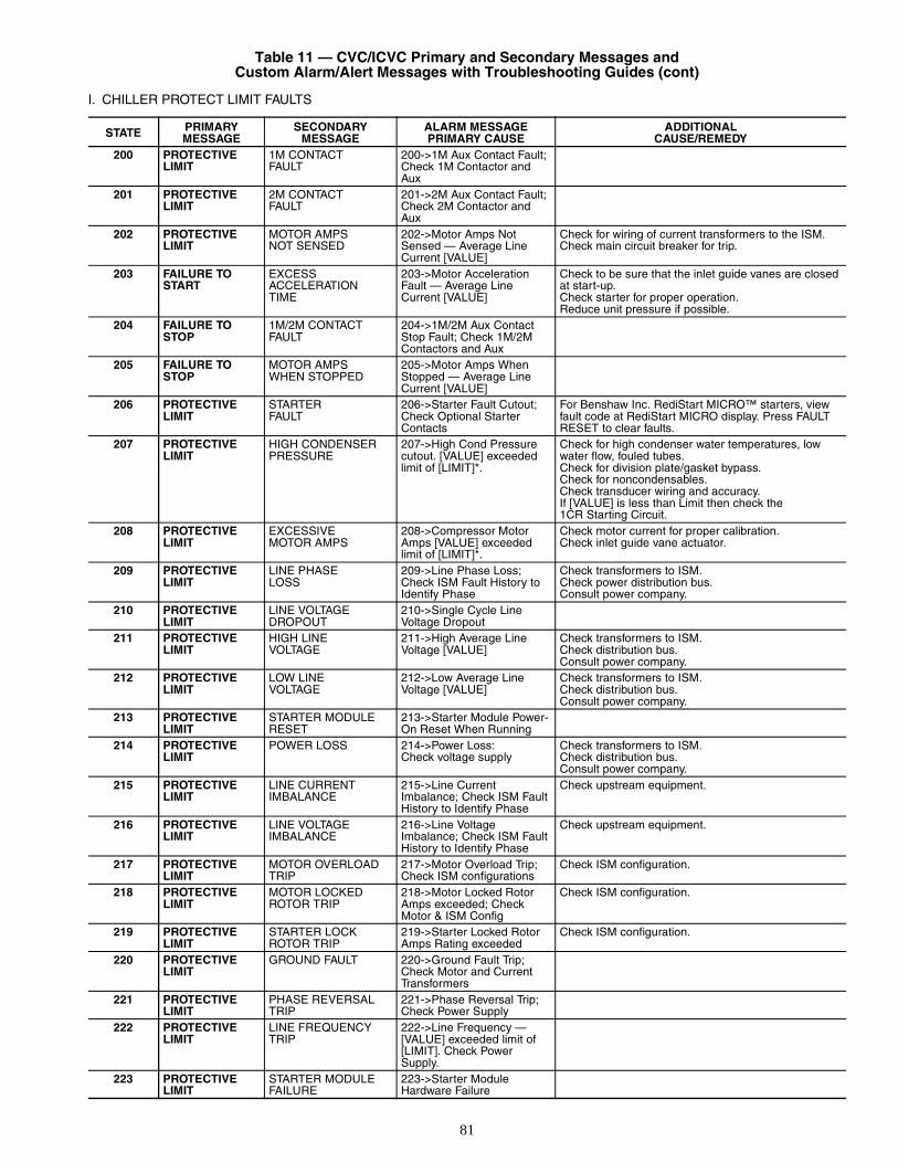
81
Table 11 — CVC/ICVC Primary and Secondary Messages andCustom Alarm/Alert Messages with Troubleshooting Guides (cont)
I. CHILLER PROTECT LIMIT FAULTS
STATE PRIMARYMESSAGE
SECONDARYMESSAGE
ALARM MESSAGEPRIMARY CAUSE
ADDITIONALCAUSE/REMEDY
200 PROTECTIVELIMIT
1M CONTACTFAULT
200->1M Aux Contact Fault; Check 1M Contactor and Aux
201 PROTECTIVELIMIT
2M CONTACTFAULT
201->2M Aux Contact Fault; Check 2M Contactor and Aux
202 PROTECTIVELIMIT
MOTOR AMPSNOT SENSED
202->Motor Amps Not Sensed — Average Line Current [VALUE]
Check for wiring of current transformers to the ISM.Check main circuit breaker for trip.
203 FAILURE TOSTART
EXCESSACCELERATIONTIME
203->Motor Acceleration Fault — Average LineCurrent [VALUE]
Check to be sure that the inlet guide vanes are closed at start-up.Check starter for proper operation.Reduce unit pressure if possible.
204 FAILURE TOSTOP
1M/2M CONTACTFAULT
204->1M/2M Aux Contact Stop Fault; Check 1M/2M Contactors and Aux
205 FAILURE TOSTOP
MOTOR AMPSWHEN STOPPED
205->Motor Amps When Stopped — Average Line Current [VALUE]
206 PROTECTIVELIMIT
STARTERFAULT
206->Starter Fault Cutout; Check Optional StarterContacts
For Benshaw Inc. RediStart MICRO™ starters, view fault code at RediStart MICRO display. Press FAULT RESET to clear faults.
207 PROTECTIVELIMIT
HIGH CONDENSERPRESSURE
207->High Cond Pressure cutout. [VALUE] exceeded limit of [LIMIT]*.
Check for high condenser water temperatures, low water flow, fouled tubes.Check for division plate/gasket bypass.Check for noncondensables.Check transducer wiring and accuracy.If [VALUE] is less than Limit then check the 1CR Starting Circuit.
208 PROTECTIVELIMIT
EXCESSIVEMOTOR AMPS
208->Compressor Motor Amps [VALUE] exceeded limit of [LIMIT]*.
Check motor current for proper calibration.Check inlet guide vane actuator.
209 PROTECTIVELIMIT
LINE PHASELOSS
209->Line Phase Loss; Check ISM Fault History to Identify Phase
Check transformers to ISM.Check power distribution bus.Consult power company.
210 PROTECTIVELIMIT
LINE VOLTAGEDROPOUT
210->Single Cycle LineVoltage Dropout
211 PROTECTIVELIMIT
HIGH LINEVOLTAGE
211->High Average Line Voltage [VALUE]
Check transformers to ISM.Check distribution bus.Consult power company.
212 PROTECTIVELIMIT
LOW LINEVOLTAGE
212->Low Average LineVoltage [VALUE]
Check transformers to ISM.Check distribution bus.Consult power company.
213 PROTECTIVELIMIT
STARTER MODULERESET
213->Starter Module Power-On Reset When Running
214 PROTECTIVELIMIT
POWER LOSS 214->Power Loss:Check voltage supply
Check transformers to ISM.Check distribution bus.Consult power company.
215 PROTECTIVELIMIT
LINE CURRENTIMBALANCE
215->Line CurrentImbalance; Check ISM Fault History to Identify Phase
Check upstream equipment.
216 PROTECTIVELIMIT
LINE VOLTAGEIMBALANCE
216->Line VoltageImbalance; Check ISM Fault History to Identify Phase
Check upstream equipment.
217 PROTECTIVELIMIT
MOTOR OVERLOADTRIP
217->Motor Overload Trip; Check ISM configurations
Check ISM configuration.
218 PROTECTIVELIMIT
MOTOR LOCKEDROTOR TRIP
218->Motor Locked Rotor Amps exceeded; Check Motor & ISM Config
Check ISM configuration.
219 PROTECTIVELIMIT
STARTER LOCKROTOR TRIP
219->Starter Locked Rotor Amps Rating exceeded
Check ISM configuration.
220 PROTECTIVELIMIT
GROUND FAULT 220->Ground Fault Trip; Check Motor and Current Transformers
221 PROTECTIVELIMIT
PHASE REVERSALTRIP
221->Phase Reversal Trip; Check Power Supply
222 PROTECTIVELIMIT
LINE FREQUENCYTRIP
222->Line Frequency — [VALUE] exceeded limit of [LIMIT]. Check PowerSupply.
223 PROTECTIVELIMIT
STARTER MODULEFAILURE
223->Starter ModuleHardware Failure
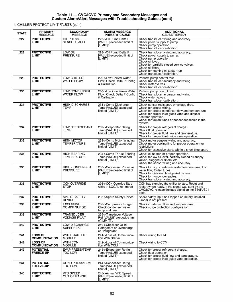
82
Table 11 — CVC/ICVC Primary and Secondary Messages andCustom Alarm/Alert Messages with Troubleshooting Guides (cont)
I. CHILLER PROTECT LIMIT FAULTS (cont)
STATE PRIMARYMESSAGE
SECONDARYMESSAGE
ALARM MESSAGEPRIMARY CAUSE
ADDITIONALCAUSE/REMEDY
227 PROTECTIVELIMIT
OIL PRESSSENSOR FAULT
227->Oil Pump Delta P [VALUE] exceeded limit of [LIMIT]*.
Check transducer wiring and accuracy.Check power supply to pump.Check pump operation.Check transducer calibration.
228 PROTECTIVELIMIT
LOW OILPRESSURE
228->Oil Pump Delta P [VALUE] exceeded limit of [LIMIT].*
Check transducer wiring and accuracy.Check power supply to pump.Check pump operation.Check oil level.Check for partially closed service valves.Check oil filters.Check for foaming oil at start-up.Check transducer calibration.
229 PROTECTIVELIMIT
LOW CHILLEDWATER FLOW
229->Low Chilled Water Flow; Check Delta P Config & Calibration
Perform pump control test.Check transducer accuracy and wiring.Check water valves.Check transducer calibration.
230 PROTECTIVELIMIT
LOW CONDENSERWATER FLOW
230->Low Condenser Water Flow; Check Delta P Config & Calibration
Perform pump control test.Check transducer accuracy and wiring.Check water valves.Check transducer calibration.
231 PROTECTIVELIMIT
HIGH DISCHARGETEMP
231->Comp Discharge Temp [VALUE] exceeded limit of [LIMIT].*
Check sensor resistance or voltage drop.Check for proper wiring.Check for proper condenser flow and temperature.Check for proper inlet guide vane and diffuseractuator operation.Check for fouled tubes or noncondensables in the system.
232 PROTECTIVELIMIT
LOW REFRIGERANTTEMP
232->Evaporator Refrig Temp [VALUE] exceeded limit of [LIMIT]*.
Check for proper refrigerant charge.Check float operation.Check for proper fluid flow and temperature.Check for proper inlet guide vane operation.
233 PROTECTIVELIMIT
HIGH MOTORTEMPERATURE
233->Comp Motor Winding Temp [VALUE] exceeded limit of [LIMIT]*.
Check motor sensors wiring and accuracy.Check motor cooling line for proper operation, or restrictions.Check for excessive starts within a short time span.
234 PROTECTIVELIMIT
HIGH BEARINGTEMPERATURE
234->Comp Thrust Bearing Temp [VALUE] exceeded limit of [LIMIT]*.
Check oil heater for proper operation.Check for low oil level, partially closed oil supply valves, clogged oil filters, etc.Check the sensor wiring and accuracy.
235 PROTECTIVELIMIT
HIGH CONDENSERPRESSURE
235->Condenser Pressure [VALUE] exceeded limit of [LIMIT]*.
Check for high condenser water temperatures, low water flow, fouled tubes.Check for division plate/gasket bypass.Check for noncondensables.Check transducer wiring and accuracy.
236 PROTECTIVELIMIT
CCN OVERRIDESTOP
236->CCN Override Stop while in LOCAL run mode
CCN has signaled the chiller to stop. Reset and restart when ready. If the signal was sent by the CVC/ICVC, release the stop signal on the STATUS01 table.
237 PROTECTIVELIMIT
SPARE SAFETYDEVICE
237->Spare Safety Device Spare safety input has tripped or factory installed jumper is not present.
238 PROTECTIVELIMIT
EXCESSIVECOMPR SURGE
238->Compressor Surge: Check condenser water temp and flow
Check condenser flow and temperatures.Check surge protection configuration.
239 PROTECTIVELIMIT
TRANSDUCERVOLTAGE FAULT
239->Transducer Voltage Ref [VALUE] exceeded limit of [LIMIT]*.
240 PROTECTIVELIMIT
LOW DISCHARGESUPERHEAT
240->Check for Oil inRefrigerant or Overcharge of Refrigerant
241 LOSS OFCOMMUNICATION
WITH STARTERMODULE
241->Loss of Communica-tion With Starter.
Check wiring to ISM.
242 LOSS OFCOMMUNICATION
WITH CCMMODULE
242->Loss of Communica-tion With CCM.
Check wiring to CCM.
243 POTENTIALFREEZE-UP
EVAP PRESS/TEMPTOO LOW
243->Evaporator Refrig Temp [VALUE] exceeded limit of [LIMIT]*.
Check for proper refrigerant charge.Check float operation.Check for proper fluid flow and temperature.Check for proper inlet guide vane operation.
244 POTENTIALFREEZE-UP
COND PRESS/TEMPTOO LOW
244->Condenser Refrig Temp [VALUE] exceeded limit of [LIMIT]*.
245 PROTECTIVELIMIT
VFD SPEEDOUT OF RANGE
245->Actual VFD Speed [VALUE] exceeded limit of [LIMIT]*.
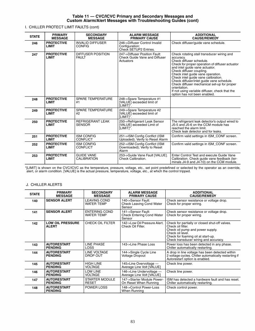
83
Table 11 — CVC/ICVC Primary and Secondary Messages andCustom Alarm/Alert Messages with Troubleshooting Guides (cont)
I. CHILLER PROTECT LIMIT FAULTS (cont)
*[LIMIT] is shown on the CVC/ICVC as the temperature, pressure, voltage, etc., set point predefined or selected by the operator as an override,alert, or alarm condition. [VALUE] is the actual pressure, temperature, voltage, etc., at which the control tripped.
J. CHILLER ALERTS
STATE PRIMARYMESSAGE
SECONDARYMESSAGE
ALARM MESSAGEPRIMARY CAUSE
ADDITIONALCAUSE/REMEDY
246 PROTECTIVELIMIT
INVALID DIFFUSERCONFIG
246->Diffuser Control InvalidConfiguration:Check SETUP2 Entries.
Check diffuser/guide vane schedule.
247 PROTECTIVELIMIT
DIFFUSER POSITIONFAULT
247->Diffuser Position Fault:Check Guide Vane and DiffuserActuators
Check rotating stall transducer wiring and accuracy.Check diffuser schedule.Check for proper operation of diffuser actuator and inlet guide vane actuator.Check diffuser coupling.Check inlet guide vane operation.Check inlet guide vane calibration.Check diffuser/inlet guide vane schedule.Check diffuser mechanical set-up for proper orientation.If not using variable diffuser, check that the option has not been enabled.
248 PROTECTIVELIMIT
SPARE TEMPERATURE#1
248->Spare Temperature #1 [VALUE] exceeded limit of [LIMIT]*.
249 PROTECTIVELIMIT
SPARE TEMPERATURE#2
249->Spare Temperature #2 [VALUE] exceeded limit of [LIMIT]*.
250 PROTECTIVELIMIT
REFRIGERANT LEAKSENSOR
250->Refrigerant Leak Sensor [VALUE] exceeded Limit of [LIMIT]*.
The refrigerant leak detector’s output wired to J5-5 and J5-6 on the CCM module has reached the alarm limit.Check leak detector and for leaks.
251 PROTECTIVELIMIT
ISM CONFIGCONFLICT
251->ISM Config Conflict (ISM Uploaded); Verify to Reset Alarm
Confirm valid settings in ISM_CONF screen.
252 PROTECTIVELIMIT
ISM CONFIGCONFLICT
252->ISM Config Conflict (ISM Downloaded); Verify to Reset Alarm
Confirm valid settings in ISM_CONF screen.
253 PROTECTIVELIMIT
GUIDE VANECALIBRATION
253->Guide Vane Fault [VALUE]. Check Calibration.
Enter Control Test and execute Guide Vane Calibration. Check guide vane feedback (ter-minals J4-9 and J4-10) on the CCM module.
STATE PRIMARYMESSAGE
SECONDARYMESSAGE
ALARM MESSAGEPRIMARY CAUSE
ADDITIONALCAUSE/REMEDY
140 SENSOR ALERT LEAVING CONDWATER TEMP
140->Sensor Fault:Check Leaving Cond Water Sensor
Check sensor resistance or voltage drop.Check for proper wiring.
141 SENSOR ALERT ENTERING CONDWATER TEMP
141->Sensor Fault:Check Entering Cond Water Sensor
Check sensor resistance or voltage drop.Check for proper wiring.
142 LOW OIL PRESSUREALERT
CHECK OIL FILTER 142->Low Oil Pressure Alert. Check Oil Filter.
Check for partially or closed shut-off valves.Check oil filter.Check oil pump and power supply.Check oil level.Check for foaming oil at start-up.Check transducer wiring and accuracy.
143 AUTORESTARTPENDING
LINE PHASELOSS
143->Line Phase Loss Power loss has been detected in any phase.Chiller automatically restarting.
144 AUTORESTARTPENDING
LINE VOLTAGEDROP OUT
144->Single Cycle LineVoltage Dropout
A drop in line voltage has been detected within2 voltage cycles. Chiller automatically restarting if Autorestart option is enabled.
145 AUTORESTARTPENDING
HIGH LINEVOLTAGE
145>Line Overvoltage — Average Line Volt [VALUE]
Check line power.
146 AUTORESTARTPENDING
LOW LINEVOLTAGE
146->Line Undervoltage — Average Line Volt [VALUE]
Check line power.
147 AUTORESTARTPENDING
STARTER MODULERESET
147->Starter Module Power-On Reset When Running
ISM has detected a hardware fault and has reset.Chiller automatically restarting.
148 AUTORESTARTPENDING
POWER LOSS 148->Control Power-Loss When Running
Check control power.
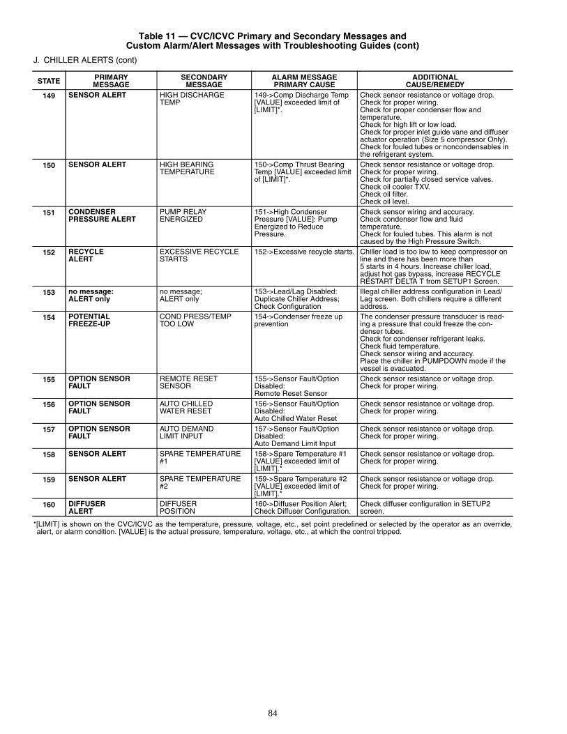
84
Table 11 — CVC/ICVC Primary and Secondary Messages andCustom Alarm/Alert Messages with Troubleshooting Guides (cont)
J. CHILLER ALERTS (cont)
*[LIMIT] is shown on the CVC/ICVC as the temperature, pressure, voltage, etc., set point predefined or selected by the operator as an override,alert, or alarm condition. [VALUE] is the actual pressure, temperature, voltage, etc., at which the control tripped.
STATE PRIMARYMESSAGE
SECONDARYMESSAGE
ALARM MESSAGEPRIMARY CAUSE
ADDITIONALCAUSE/REMEDY
149 SENSOR ALERT HIGH DISCHARGETEMP
149->Comp Discharge Temp [VALUE] exceeded limit of [LIMIT]*.
Check sensor resistance or voltage drop.Check for proper wiring.Check for proper condenser flow andtemperature.Check for high lift or low load.Check for proper inlet guide vane and diffuser actuator operation (Size 5 compressor Only).Check for fouled tubes or noncondensables in the refrigerant system.
150 SENSOR ALERT HIGH BEARINGTEMPERATURE
150->Comp Thrust Bearing Temp [VALUE] exceeded limit of [LIMIT]*.
Check sensor resistance or voltage drop.Check for proper wiring.Check for partially closed service valves.Check oil cooler TXV.Check oil filter.Check oil level.
151 CONDENSER PRESSURE ALERT
PUMP RELAYENERGIZED
151->High CondenserPressure [VALUE]: PumpEnergized to ReducePressure.
Check sensor wiring and accuracy.Check condenser flow and fluidtemperature.Check for fouled tubes. This alarm is not caused by the High Pressure Switch.
152 RECYCLEALERT
EXCESSIVE RECYCLESTARTS
152->Excessive recycle starts. Chiller load is too low to keep compressor on line and there has been more than5 starts in 4 hours. Increase chiller load, adjust hot gas bypass, increase RECYCLE RESTART DELTA T from SETUP1 Screen.
153 no message:ALERT only
no message;ALERT only
153->Lead/Lag Disabled:Duplicate Chiller Address; Check Configuration
Illegal chiller address configuration in Lead/Lag screen. Both chillers require a different address.
154 POTENTIALFREEZE-UP
COND PRESS/TEMPTOO LOW
154->Condenser freeze upprevention
The condenser pressure transducer is read-ing a pressure that could freeze the con-denser tubes.Check for condenser refrigerant leaks.Check fluid temperature.Check sensor wiring and accuracy.Place the chiller in PUMPDOWN mode if the vessel is evacuated.
155 OPTION SENSORFAULT
REMOTE RESETSENSOR
155->Sensor Fault/OptionDisabled:Remote Reset Sensor
Check sensor resistance or voltage drop.Check for proper wiring.
156 OPTION SENSORFAULT
AUTO CHILLEDWATER RESET
156->Sensor Fault/OptionDisabled:Auto Chilled Water Reset
Check sensor resistance or voltage drop.Check for proper wiring.
157 OPTION SENSORFAULT
AUTO DEMANDLIMIT INPUT
157->Sensor Fault/OptionDisabled:Auto Demand Limit Input
Check sensor resistance or voltage drop.Check for proper wiring.
158 SENSOR ALERT SPARE TEMPERATURE#1
158->Spare Temperature #1 [VALUE] exceeded limit of [LIMIT].*
Check sensor resistance or voltage drop.Check for proper wiring.
159 SENSOR ALERT SPARE TEMPERATURE#2
159->Spare Temperature #2 [VALUE] exceeded limit of [LIMIT].*
Check sensor resistance or voltage drop.Check for proper wiring.
160 DIFFUSERALERT
DIFFUSERPOSITION
160->Diffuser Position Alert;Check Diffuser Configuration.
Check diffuser configuration in SETUP2 screen.
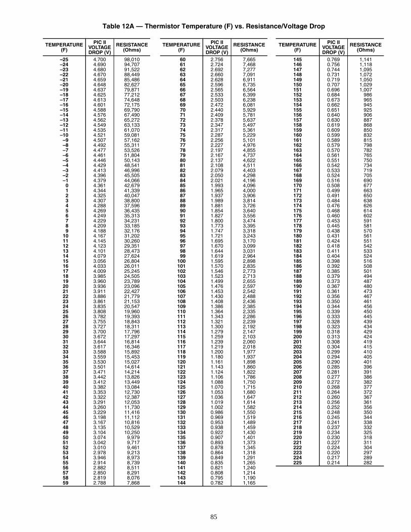
85
Table 12A — Thermistor Temperature (F) vs. Resistance/Voltage Drop
TEMPERATURE(F)
PIC IIVOLTAGEDROP (V)
RESISTANCE(Ohms)
–25 4.700 98,010–24 4.690 94,707–23 4.680 91,522–22 4.670 88,449–21 4.659 85,486–20 4.648 82,627–19 4.637 79,871–18 4.625 77,212–17 4.613 74,648–16 4.601 72,175–15 4.588 69,790–14 4.576 67,490–13 4.562 65,272–12 4.549 63,133–11 4.535 61,070–10 4.521 59,081
–9 4.507 57,162–8 4.492 55,311–7 4.477 53,526–6 4.461 51,804–5 4.446 50,143–4 4.429 48,541–3 4.413 46,996–2 4.396 45,505–1 4.379 44,066
0 4.361 42,6791 4.344 41,3392 4.325 40,0473 4.307 38,8004 4.288 37,5965 4.269 36,4356 4.249 35,3137 4.229 34,2318 4.209 33,1859 4.188 32,176
10 4.167 31,20211 4.145 30,26012 4.123 29,35113 4.101 28,47314 4.079 27,62415 3.056 26,80416 4.033 26,01117 4.009 25,24518 3.985 24,50519 3.960 23,78920 3.936 23,09621 3.911 22,42722 3.886 21,77923 3.861 21,15324 3.835 20,54725 3.808 19,96026 3.782 19,39327 3.755 18,84328 3.727 18,31129 3.700 17,79630 3.672 17,29731 3.644 16,81432 3.617 16,34633 3.588 15,89234 3.559 15,45335 3.530 15,02736 3.501 14,61437 3.471 14,21438 3.442 13,82639 3.412 13,44940 3.382 13,08441 3.353 12,73042 3.322 12,38743 3.291 12,05344 3.260 11,73045 3.229 11,41646 3.198 11,11247 3.167 10,81648 3.135 10,52949 3.104 10,25050 3.074 9,97951 3.042 9,71752 3.010 9,46153 2.978 9,21354 3.946 8,97355 2.914 8,73956 2.882 8,51157 2.850 8,29158 2.819 8,07659 2.788 7,868
TEMPERATURE(F)
PIC IIVOLTAGEDROP (V)
RESISTANCE(Ohms)
60 2.756 7,66561 2.724 7,46862 2.692 7,27763 2.660 7,09164 2.628 6,91165 2.596 6,73566 2.565 6,56467 2.533 6,39968 2.503 6,23869 2.472 6,08170 2.440 5,92971 2.409 5,78172 2.378 5,63773 2.347 5,49774 2.317 5,36175 2.287 5,22976 2.256 5,10177 2.227 4,97678 2.197 4,85579 2.167 4,73780 2.137 4,62281 2.108 4,51182 2.079 4,40383 2.050 4,29884 2.021 4,19685 1.993 4,09686 1.965 4,00087 1.937 3,90688 1.989 3,81489 1.881 3,72690 1.854 3,64091 1.827 3,55692 1.800 3,47493 1.773 3,39594 1.747 3,31895 1.721 3,24396 1.695 3,17097 1.670 3,09998 1.644 3,03199 1.619 2,964
100 1.595 2,898101 1.570 2,835102 1.546 2,773103 1.523 2,713104 1.499 2,655105 1.476 2,597106 1.453 2,542107 1.430 2,488108 1.408 2,436109 1.386 2,385110 1.364 2,335111 1.343 2,286112 1.321 2,239113 1.300 2,192114 1.279 2,147115 1.259 2,103116 1.239 2,060117 1.219 2,018118 1.200 1,977119 1.180 1,937120 1.161 1,898121 1.143 1,860122 1.124 1,822123 1.106 1,786124 1.088 1,750125 1.070 1,715126 1.053 1,680127 1.036 1,647128 1.019 1,614129 1.002 1,582130 0.986 1,550131 0.969 1,519132 0.953 1,489133 0.938 1,459134 0.922 1,430135 0.907 1,401136 0.893 1,373137 0.878 1,345138 0.864 1,318139 0.849 1,291140 0.835 1,265141 0.821 1,240142 0.808 1,214143 0.795 1,190144 0.782 1,165
TEMPERATURE(F)
PIC IIVOLTAGEDROP (V)
RESISTANCE(Ohms)
145 0.769 1,141146 0.756 1,118147 0.744 1,095148 0.731 1,072149 0.719 1,050150 0.707 1,029151 0.696 1,007152 0.684 986153 0.673 965154 0.662 945155 0.651 925156 0.640 906157 0.630 887158 0.619 868159 0.609 850160 0.599 832161 0.589 815162 0.579 798163 0.570 782164 0.561 765165 0.551 750166 0.542 734167 0.533 719168 0.524 705169 0.516 690170 0.508 677171 0.499 663172 0.491 650173 0.484 638174 0.476 626175 0.468 614176 0.460 602177 0.453 591178 0.445 581179 0.438 570180 0.431 561181 0.424 551182 0.418 542183 0.411 533184 0.404 524185 0.398 516186 0.392 508187 0.385 501188 0.379 494189 0.373 487190 0.367 480191 0.361 473192 0.356 467193 0.350 461194 0.344 456195 0.339 450196 0.333 445197 0.328 439198 0.323 434199 0.318 429200 0.313 424201 0.308 419202 0.304 415203 0.299 410204 0.294 405205 0.290 401206 0.285 396207 0.281 391208 0.277 386209 0.272 382210 0.268 377211 0.264 372212 0.260 367213 0.256 361214 0.252 356215 0.248 350216 0.245 344217 0.241 338218 0.237 332219 0.234 325220 0.230 318221 0.227 311222 0.224 304223 0.220 297224 0.217 289225 0.214 282
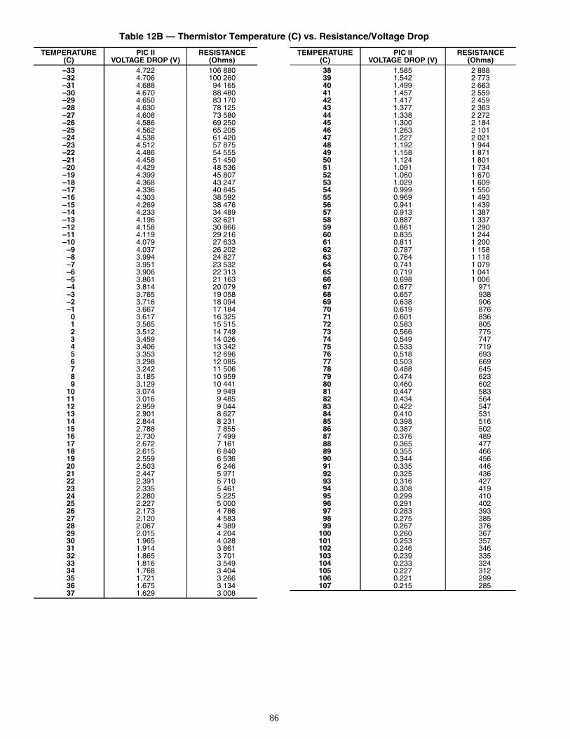
86
Table 12B — Thermistor Temperature (C) vs. Resistance/Voltage Drop
TEMPERATURE(C)
PIC IIVOLTAGE DROP (V)
RESISTANCE(Ohms)
–33 4.722 106 880–32 4.706 100 260–31 4.688 94 165–30 4.670 88 480–29 4.650 83 170–28 4.630 78 125–27 4.608 73 580–26 4.586 69 250–25 4.562 65 205–24 4.538 61 420–23 4.512 57 875–22 4.486 54 555–21 4.458 51 450–20 4.429 48 536–19 4.399 45 807–18 4.368 43 247–17 4.336 40 845–16 4.303 38 592–15 4.269 38 476–14 4.233 34 489–13 4.196 32 621–12 4.158 30 866–11 4.119 29 216–10 4.079 27 633
–9 4.037 26 202–8 3.994 24 827–7 3.951 23 532–6 3.906 22 313–5 3.861 21 163–4 3.814 20 079–3 3.765 19 058–2 3.716 18 094–1 3.667 17 184
0 3.617 16 3251 3.565 15 5152 3.512 14 7493 3.459 14 0264 3.406 13 3425 3.353 12 6966 3.298 12 0857 3.242 11 5068 3.185 10 9599 3.129 10 441
10 3.074 9 94911 3.016 9 48512 2.959 9 04413 2.901 8 62714 2.844 8 23115 2.788 7 85516 2.730 7 49917 2.672 7 16118 2.615 6 84019 2.559 6 53620 2.503 6 24621 2.447 5 97122 2.391 5 71023 2.335 5 46124 2.280 5 22525 2.227 5 00026 2.173 4 78627 2.120 4 58328 2.067 4 38929 2.015 4 20430 1.965 4 02831 1.914 3 86132 1.865 3 70133 1.816 3 54934 1.768 3 40435 1.721 3 26636 1.675 3 13437 1.629 3 008
TEMPERATURE(C)
PIC IIVOLTAGE DROP (V)
RESISTANCE(Ohms)
38 1.585 2 88839 1.542 2 77340 1.499 2 66341 1.457 2 55942 1.417 2 45943 1.377 2 36344 1.338 2 27245 1.300 2 18446 1.263 2 10147 1.227 2 02148 1.192 1 94449 1.158 1 87150 1.124 1 80151 1.091 1 73452 1.060 1 67053 1.029 1 60954 0.999 1 55055 0.969 1 49356 0.941 1 43957 0.913 1 38758 0.887 1 33759 0.861 1 29060 0.835 1 24461 0.811 1 20062 0.787 1 15863 0.764 1 11864 0.741 1 07965 0.719 1 04166 0.698 1 00667 0.677 97168 0.657 93869 0.638 90670 0.619 87671 0.601 83672 0.583 80573 0.566 77574 0.549 74775 0.533 71976 0.518 69377 0.503 66978 0.488 64579 0.474 62380 0.460 60281 0.447 58382 0.434 56483 0.422 54784 0.410 53185 0.398 51686 0.387 50287 0.376 48988 0.365 47789 0.355 46690 0.344 45691 0.335 44692 0.325 43693 0.316 42794 0.308 41995 0.299 41096 0.291 40297 0.283 39398 0.275 38599 0.267 376
100 0.260 367101 0.253 357102 0.246 346103 0.239 335104 0.233 324105 0.227 312106 0.221 299107 0.215 285
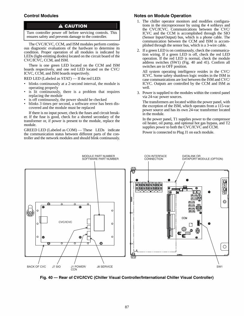
87
Control Modules
The CVC/ICVC, CCM, and ISM modules perform continu-ous diagnostic evaluations of the hardware to determine itscondition. Proper operation of all modules is indicated byLEDs (light-emitting diodes) located on the circuit board of theCVC/ICVC, CCM, and ISM.
There is one green LED located on the CCM and ISMboards respectively, and one red LED located on the CVC/ICVC, CCM, and ISM boards respectively.RED LED (Labeled as STAT) — If the red LED:• blinks continuously at a 2-second interval, the module is
operating properly• is lit continuously, there is a problem that requires
replacing the module• is off continuously, the power should be checked• blinks 3 times per second, a software error has been dis-
covered and the module must be replacedIf there is no input power, check the fuses and circuit break-
er. If the fuse is good, check for a shorted secondary of thetransformer or, if power is present to the module, replace themodule.GREED LED (Labeled as COM) — These LEDs indicatethe communication status between different parts of the con-troller and the network modules and should blink continuously.
Notes on Module Operation1. The chiller operator monitors and modifies configura-
tions in the microprocessor by using the 4 softkeys andthe CVC/ICVC. Communications between the CVC/ICVC and the CCM is accomplished through the SIO(Sensor Input/Output) bus, which is a phone cable. Thecommunication between the CCM and ISM is accom-plished through the sensor bus, which is a 3-wire cable.
2. If a green LED is on continuously, check the communica-tion wiring. If a green LED is off, check the red LEDoperation. If the red LED is normal, check the moduleaddress switches (SW1) (Fig. 40 and 41). Confirm allswitches are in OFF position.All system operating intelligence resides in the CVC/ICVC. Some safety shutdown logic resides in the ISM incase communications are lost between the ISM and CVC/ICVC. Outputs are controlled by the CCM and ISM aswell.
3. Power is supplied to the modules within the control panelvia 24-vac power sources.The transformers are located within the power panel, withthe exception of the ISM, which operates from a 115-vacpower source and has its own 24-vac transformer locatedin the module.In the power panel, T1 supplies power to the compressoroil heater, oil pump, and optional hot gas bypass, and T2supplies power to both the CVC/ICVC and CCM.Power is connected to Plug J1 on each module.
Turn controller power off before servicing controls. Thisensures safety and prevents damage to the controller.
CCN INTERFACECONNECTION
DATALINK ORDATAPORT MODULE (OPTION)
SW1BACK OF CVC
MODULE PART NUMBERSOFTWARE PART NUMBER
J7 SIO J1 POWER/CCN
J8 SERVICE
CVC/ICVC
Fig. 40 — Rear of CVC/ICVC (Chiller Visual Controller/International Chiller Visual Controller)
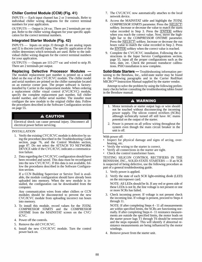
88
Chiller Control Module (CCM) (Fig. 41)INPUTS — Each input channel has 2 or 3 terminals. Refer toindividual chiller wiring diagrams for the correct terminalnumbers for your application.OUTPUTS — Output is 24 vac. There are 2 terminals per out-put. Refer to the chiller wiring diagram for your specific appli-cation for the correct terminal numbers.
Integrated Starter Module (Fig. 42)INPUTS — Inputs on strips J3 through J6 are analog inputsand J2 is discrete (on/off) input. The specific application of thechiller determines which terminals are used. Refer to the indi-vidual chiller wiring diagram for the correct terminal numbersfor your application.OUTPUTS — Outputs are 115-277 vac and wired to strip J9.There are 2 terminals per output.
Replacing Defective Processor Modules —The module replacement part number is printed on a smalllabel on the rear of the CVC/ICVC module. The chiller modeland serial numbers are printed on the chiller nameplate locatedon an exterior corner post. The proper software is factory-installed by Carrier in the replacement module. When orderinga replacement chiller visual control (CVC/ICVC) module,specify the complete replacement part number, full chillermodel number, and chiller serial number. The installer mustconfigure the new module to the original chiller data. Followthe procedures described in the Software Configuration sectionon page 55.
INSTALLATION1. Verify the existing CVC/ICVC module is defective by us-
ing the procedure described in the Troubleshooting Guidesection, page 76, and the Control Modules section,page 87. Do not select the ATTACH TO NETWORKDEVICE table if the CVC/ICVC indicates a communica-tion failure.
2. Data regarding the CVC/ICVC configuration should havebeen recorded and saved. This data must be reconfiguredinto the new CVC/ICVC. If this data is not available, fol-low the procedures described in the Software Configura-tion section.If a CCN Building Supervisor or Service Tool is avail-able, the module configuration should have already beenuploaded into memory. When the new module is in-stalled, the configuration can be downloaded from thecomputer.Any communication wires from other chillers or CCNmodules should be disconnected to prevent the newCVC/ICVC module from uploading incorrect run hoursinto memory.
3. To install this module, record values for the TOTALCOMPRESSOR STARTS and the COMPRESSORONTIME from the MAINSTAT screen on the CVC/ICVC.
4. Power off the controls.5. Remove the old CVC/ICVC.6. Install the new CVC/ICVC module. Turn the control
power back on.
7. The CVC/ICVC now automatically attaches to the localnetwork device.
8. Access the MAINSTAT table and highlight the TOTALCOMPRESSOR STARTS parameter. Press the softkey. Increase or decrease the value to match the startsvalue recorded in Step 3. Press the softkeywhen you reach the correct value. Now, move the high-light bar to the COMPRESSOR ONTIME parameter.Press the softkey. Increase or decrease the runhours value to match the value recorded in Step 2. Pressthe softkey when the correct value is reached.
9. Complete the CVC/ICVC installation. Following the in-structions in the Input Service Configurations section,page 55, input all the proper configurations such as thetime, date, etc. Check the pressure transducer calibra-tions. PSIO installation is now complete.
Solid-State Starters — Troubleshooting information per-taining to the Benshaw, Inc., solid-state starter may be foundin the following paragraphs and in the Carrier RediStartMICRO™ Instruction Manual supplied by the starter vendor.
Attempt to solve the problem by using the following prelim-inary checks before consulting the troubleshooting tables foundin the Benshaw manual.
With power off:• Inspect for physical damage and signs of arcing, over-
heating, etc.• Verify the wiring to the starter is correct.• Verify all connections in the starter are tight.• Check the control transformer fuses.TESTING SILICON CONTROL RECTIFIERS IN THEBENSHAW, INC., SOLID-STATE STARTERS — If an SCRis suspected of being defective, use the following procedure aspart of a general troubleshooting guide.
1. Verify power is applied.2. Verify the state of each SCR light-emitting diode (LED)
on the micropower card.NOTE: All LEDs should be lit. If any red or green side ofthese LEDs is not lit, the line voltage is not present or oneor more SCRs has failed.
3. Check incoming power. If voltage is not present checkthe incoming line. If voltage is present, proceed to Steps 4through 11.NOTE: If after completing Steps 4 - 11 all measurementsare within specified limits, the SCRs are functioning nor-mally. If after completing Steps 4 - 11 resistance measure-ments are outside the specified limits, the motor leads onthe starter power lugs T1 through T6 should be removedand the steps repeated. This will identify if abnormal re-sistance measurements are being influenced by the motorwindings.
4. Remove power from the starter unit.
Electrical shock can cause personal injury. Disconnect allelectrical power before servicing.
1. Motor terminals or starter output lugs or wire shouldnot be touched without disconnecting the incomingpower supply. The silicon control rectifiers (SCRs)although technically turned off still have AC mainspotential on the output of the starter.
2. Power is present on all yellow wiring throughout thesystem even though the main circuit breaker in theunit is off.
SELECT
ENTER
SELECT
ENTER
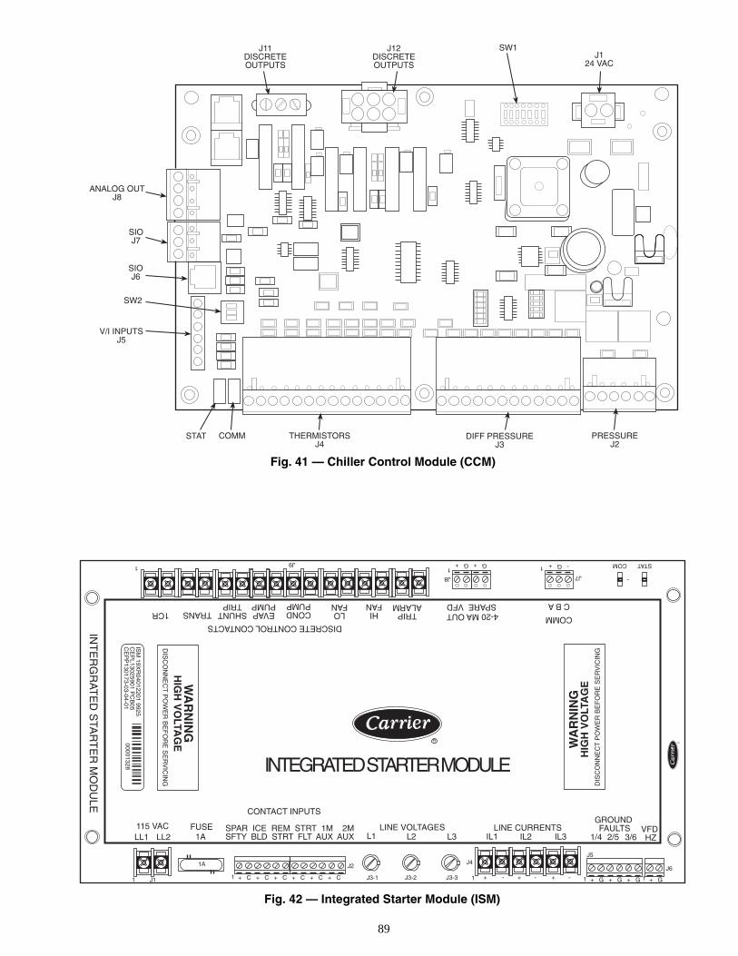
89
STAT COMM THERMISTORSJ4
DIFF PRESSUREJ3
PRESSUREJ2
SW2
V/I INPUTSJ5
SIOJ7
ANALOG OUTJ8
J11DISCRETEOUTPUTS
J12DISCRETEOUTPUTS
J124 VAC
SIOJ6
SW1
115 VACLL1 LL2 1A
CONTACT INPUTS
SPAR ICE REM STRT 1M 2MSFTY BLD STRT FLT AUX AUX
FUSE LINE VOLTAGESL1 L2 L3 IL1
LINE CURRENTSGROUND FAULTS
IL2 IL3 1/4 2/5 3/6VFD HZ
INTEGRATED STARTER MODULE
INT
ER
GR
AT
ED
STA
RT
ER
MO
DU
LE
1A
J11 1 + C + C + C + C + C + C
J2
J3-1 J3-2 J3-3
J4
1 + - + - + -
J5
1 + G + G + G + G1
J6
STATCOM
-J7
- G +1G + G +
J8
1J9
1
COMM
C B A4-20 MA OUTSPARE VFD
TRIPALARM
HIFAN
LOFAN
CONDPUMP
EVAPPUMP
SHUNTTRIP
DISCRETE CONTROL CONTACTS
TRANS1CR
R
WA
RN
ING
HIG
H V
OLTA
GE
DIS
CO
NN
EC
T P
OW
ER
BE
FO
RE
SE
RV
ICIN
G
ISM
19XR
04012201 9925C
EP
L13025901 PC
B05
CE
PP
130173-03-04-0100001328
WA
RN
ING
HIG
H V
OLT
AG
ED
ISC
ON
NE
CT
PO
WE
R B
EF
OR
E S
ER
VIC
ING
Fig. 41 — Chiller Control Module (CCM)
Fig. 42 — Integrated Starter Module (ISM)
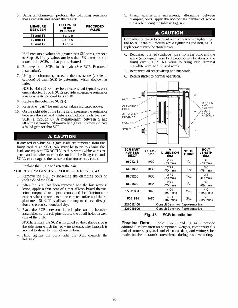
90
5. Using an ohmmeter, perform the following resistancemeasurements and record the results:
If all measured values are greater than 5K ohms, proceedto Step 10. If any values are less than 5K ohms, one ormore of the SCRs in that pair is shorted.
6. Remove both SCRs in the pair (See SCR Removal/Installation).
7. Using an ohmmeter, measure the resistance (anode tocathode) of each SCR to determine which device hasfailed.NOTE: Both SCRs may be defective, but typically, onlyone is shorted. If both SCRs provide acceptable resistancemeasurements, proceed to Step 10.
8. Replace the defective SCR(s).9. Retest the “pair” for resistance values indicated above.
10. On the right side of the firing card, measure the resistancebetween the red and white gate/cathode leads for eachSCR (1 through 6). A measurement between 5 and50 ohms is normal. Abnormally high values may indicatea failed gate for that SCR.
11. Replace the SCRs and retest the pair.SCR REMOVAL/INSTALLATION — Refer to Fig. 43.
1. Remove the SCR by loosening the clamping bolts oneach side of the SCR,
2. After the SCR has been removed and the bus work isloose, apply a thin coat of either silicon based thermaljoint compound or a joint compound for aluminum orcopper wire connections to the contact surfaces of the re-placement SCR. This allows for improved heat dissipa-tion and electrical conductivity.
3. Place the SCR between the roll pins on the heatsinkassemblies so the roll pins fit into the small holes in eachside of the SCR.NOTE: Ensure the SCR is installed so the cathode side isthe side from which the red wire extends. The heatsink islabeled to show the correct orientation.
4. Hand tighten the bolts until the SCR contacts theheatsink.
5. Using quarter-turn increments, alternating betweenclamping bolts, apply the appropriate number of wholeturns referencing the table in Fig. 43.
6. Reconnect the red (cathode) wire from the SCR and thewhite (anode-gate) wire to the appropriate location on thefiring card (i.e., SCR1 wires to firing card terminalG1-white wire, and K1-red wire).
7. Reconnect all other wiring and bus work.8. Return starter to normal operation.
Physical Data — Tables 13A-20 and Fig. 44-57 provideadditional information on component weights, compressor fitsand clearances, physical and electrical data, and wiring sche-matics for the operator’s convenience during troubleshooting.
MEASUREBETWEEN
SCR PAIRSBEING
CHECKED
RECORDEDVALUE
T1 and T6 3 and 6T2 and T4 2 and 5T3 and T5 1 and 4
If any red or white SCR gate leads are removed from thefiring card or an SCR, care must be taken to ensure theleads are replaced EXACTLY as they were (white wires togates, and red wires to cathodes on both the firing card andSCR), or damage to the starter and/or motor may result.
Care must be taken to prevent nut rotation while tighteningthe bolts. If the nut rotates while tightening the bolt, SCRreplacement must be started over.
Fig. 43 — SCR Installation
SCR PARTNUMBER BISCR
CLAMPSIZE
ADIMENSION
(in.)
NO. OFTURNS
BOLTLENGTH
(in.)
6601218 1030 2.75(70 mm) 11/2
3.0(76 mm)
6601818 1030 2.75(70 mm) 11/2
3.0(76 mm)
8801230 1035 2.75(70 mm) 13/4
3.5(89 mm)
8801830 1035 2.75(70 mm) 13/4
3.0(89 mm)
15001850 2040 4.00(102 mm) 23/4
4.0(102 mm)
15001850 2050 4.00(102 mm) 23/4
5.0(127 mm)
220012100 Consult Benshaw Representative330018500 Consult Benshaw Representative
LOOSENANDTIGHTENBOLTSFROMTHIS END
CLAMPINGBOLT
NUT
ALUMINUMHEATSINK
ROLL PIN
SCR
A
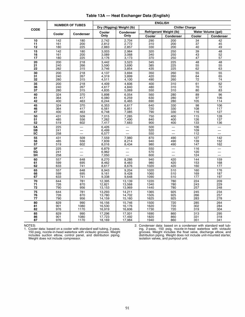
91
Table 13A — Heat Exchanger Data (English)
NOTES:1. Cooler data: based on a cooler with standard wall tubing, 2-pass,
150 psig, nozzle-in-head waterbox with victaulic grooves. Weightincludes suction elbow, control panel, and distribution piping.Weight does not include compressor.
2. Condenser data: based on a condenser with standard wall tub-ing, 2-pass, 150 psig, nozzle-in-head waterbox with victaulicgrooves. Weight includes the float valve, discharge elbow, anddistribution piping. Weight does not include unit-mounted starter,isolation valves, and pumpout unit.
CODENUMBER OF TUBES
ENGLISHDry (Rigging) Weight (lb) Chiller Charge
Cooler Condenser CoolerOnly
Condenser Only
Refrigerant Weight (lb) Water Volume (gal)Cooler Condenser Cooler Condenser
10 142 180 2,742 2,704 290 200 34 4211 161 200 2,812 2,772 310 200 37 4512 180 225 2,883 2,857 330 200 40 4915 142 180 3,003 2,984 320 250 39 4816 161 200 3,089 3,068 340 250 43 5217 180 225 3,176 3,173 370 250 47 5720 200 218 3,442 3,523 345 225 48 4821 240 266 3,590 3,690 385 225 55 5522 282 315 3,746 3,854 435 225 62 6330 200 218 4,137 3,694 350 260 55 5531 240 267 4,319 3,899 420 260 64 6532 280 315 4,511 4,100 490 260 72 7435 200 218 4,409 4,606 400 310 61 6236 240 267 4,617 4,840 480 310 70 7237 280 315 4,835 5,069 550 310 80 8340 324 370 5,898 6,054 560 280 89 9641 364 417 6,080 6,259 630 280 97 10642 400 463 6,244 6,465 690 280 105 11445 324 370 6,353 6,617 640 330 98 10646 364 417 6,561 6,851 720 330 108 11747 400 463 6,748 7,085 790 330 116 12750 431 509 7,015 7,285 750 400 115 12851 485 556 7,262 7,490 840 400 126 13752 519 602 7,417 7,683 900 400 133 1365A 225 — 6,426 — 500 — 106 —5B 241 — 6,499 — 520 — 109 —5C 258 — 6,577 — 550 — 112 —55 431 509 7,559 7,980 870 490 127 14256 485 556 7,839 8,214 940 490 139 15257 519 602 8,016 8,434 980 490 147 1625F 225 — 6,879 — 550 — 116 —5G 241 — 6,962 — 570 — 120 —5H 258 — 7,050 — 600 — 124 —60 557 648 8,270 8,286 940 420 144 15961 599 695 8,462 8,483 980 420 153 16862 633 741 8,617 8,676 1020 420 160 17765 557 648 8,943 9,204 1020 510 160 17666 599 695 9,161 9,428 1060 510 169 18767 633 741 9,338 9,648 1090 510 177 19770 644 781 12,395 13,139 1220 780 224 20971 726 870 12,821 13,568 1340 780 243 22972 790 956 13,153 13,969 1440 780 257 24875 644 781 13,293 14,211 1365 925 245 23476 726 870 13,780 14,702 1505 925 266 25777 790 956 14,159 15,160 1625 925 283 27880 829 990 16,156 15,746 1500 720 285 26481 901 1080 16,530 16,176 1620 720 302 28482 976 1170 16,919 16,606 1730 720 319 30485 829 990 17,296 17,001 1690 860 313 29586 901 1080 17,723 17,492 1820 860 331 31887 976 1170 18,169 17,984 1940 860 351 341
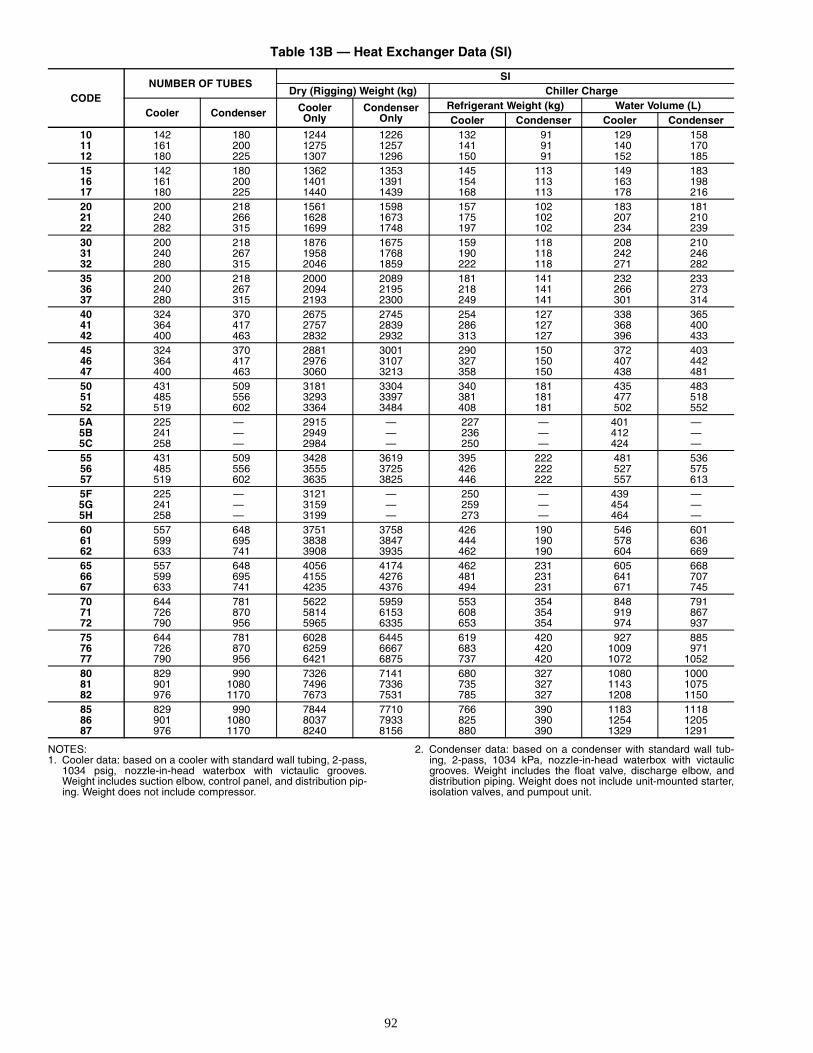
92
Table 13B — Heat Exchanger Data (SI)
NOTES:1. Cooler data: based on a cooler with standard wall tubing, 2-pass,
1034 psig, nozzle-in-head waterbox with victaulic grooves.Weight includes suction elbow, control panel, and distribution pip-ing. Weight does not include compressor.
2. Condenser data: based on a condenser with standard wall tub-ing, 2-pass, 1034 kPa, nozzle-in-head waterbox with victaulicgrooves. Weight includes the float valve, discharge elbow, anddistribution piping. Weight does not include unit-mounted starter,isolation valves, and pumpout unit.
CODENUMBER OF TUBES
SIDry (Rigging) Weight (kg) Chiller Charge
Cooler Condenser CoolerOnly
CondenserOnly
Refrigerant Weight (kg) Water Volume (L)Cooler Condenser Cooler Condenser
10 142 180 1244 1226 132 91 129 15811 161 200 1275 1257 141 91 140 17012 180 225 1307 1296 150 91 152 18515 142 180 1362 1353 145 113 149 18316 161 200 1401 1391 154 113 163 19817 180 225 1440 1439 168 113 178 21620 200 218 1561 1598 157 102 183 18121 240 266 1628 1673 175 102 207 21022 282 315 1699 1748 197 102 234 23930 200 218 1876 1675 159 118 208 21031 240 267 1958 1768 190 118 242 24632 280 315 2046 1859 222 118 271 28235 200 218 2000 2089 181 141 232 23336 240 267 2094 2195 218 141 266 27337 280 315 2193 2300 249 141 301 31440 324 370 2675 2745 254 127 338 36541 364 417 2757 2839 286 127 368 40042 400 463 2832 2932 313 127 396 43345 324 370 2881 3001 290 150 372 40346 364 417 2976 3107 327 150 407 44247 400 463 3060 3213 358 150 438 48150 431 509 3181 3304 340 181 435 48351 485 556 3293 3397 381 181 477 51852 519 602 3364 3484 408 181 502 5525A 225 — 2915 — 227 — 401 —5B 241 — 2949 — 236 — 412 —5C 258 — 2984 — 250 — 424 —55 431 509 3428 3619 395 222 481 53656 485 556 3555 3725 426 222 527 57557 519 602 3635 3825 446 222 557 6135F 225 — 3121 — 250 — 439 —5G 241 — 3159 — 259 — 454 —5H 258 — 3199 — 273 — 464 —60 557 648 3751 3758 426 190 546 60161 599 695 3838 3847 444 190 578 63662 633 741 3908 3935 462 190 604 66965 557 648 4056 4174 462 231 605 66866 599 695 4155 4276 481 231 641 70767 633 741 4235 4376 494 231 671 74570 644 781 5622 5959 553 354 848 79171 726 870 5814 6153 608 354 919 86772 790 956 5965 6335 653 354 974 93775 644 781 6028 6445 619 420 927 88576 726 870 6259 6667 683 420 1009 97177 790 956 6421 6875 737 420 1072 105280 829 990 7326 7141 680 327 1080 100081 901 1080 7496 7336 735 327 1143 107582 976 1170 7673 7531 785 327 1208 115085 829 990 7844 7710 766 390 1183 111886 901 1080 8037 7933 825 390 1254 120587 976 1170 8240 8156 880 390 1329 1291
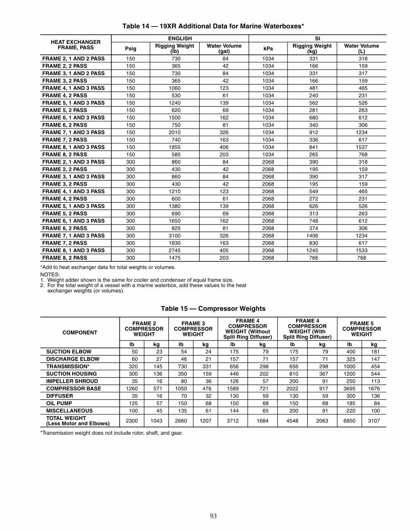
93
Table 14 — 19XR Additional Data for Marine Waterboxes*
*Add to heat exchanger data for total weights or volumes.NOTES:1. Weight adder shown is the same for cooler and condenser of equal frame size.2. For the total weight of a vessel with a marine waterbox, add these values to the heat
exchanger weights (or volumes).
Table 15 — Compressor Weights
*Transmission weight does not include rotor, shaft, and gear.
HEAT EXCHANGERFRAME, PASS
ENGLISH SI
Psig Rigging Weight(lb)
Water Volume(gal) kPa Rigging Weight
(kg)Water Volume
(L)FRAME 2, 1 AND 2 PASS 150 730 84 1034 331 318FRAME 2, 2 PASS 150 365 42 1034 166 159FRAME 3, 1 AND 2 PASS 150 730 84 1034 331 317FRAME 3, 2 PASS 150 365 42 1034 166 159FRAME 4, 1 AND 3 PASS 150 1060 123 1034 481 465FRAME 4, 2 PASS 150 530 61 1034 240 231FRAME 5, 1 AND 3 PASS 150 1240 139 1034 562 526FRAME 5, 2 PASS 150 620 69 1034 281 263FRAME 6, 1 AND 3 PASS 150 1500 162 1034 680 612FRAME 6, 2 PASS 150 750 81 1034 340 306FRAME 7, 1 AND 3 PASS 150 2010 326 1034 912 1234FRAME 7, 2 PASS 150 740 163 1034 336 617FRAME 8, 1 AND 3 PASS 150 1855 406 1034 841 1537FRAME 8, 2 PASS 150 585 203 1034 265 768FRAME 2, 1 AND 3 PASS 300 860 84 2068 390 318FRAME 2, 2 PASS 300 430 42 2068 195 159FRAME 3, 1 AND 3 PASS 300 860 84 2068 390 317FRAME 3, 2 PASS 300 430 42 2068 195 159FRAME 4, 1 AND 3 PASS 300 1210 123 2068 549 465FRAME 4, 2 PASS 300 600 61 2068 272 231FRAME 5, 1 AND 3 PASS 300 1380 139 2068 626 526FRAME 5, 2 PASS 300 690 69 2068 313 263FRAME 6, 1 AND 3 PASS 300 1650 162 2068 748 612FRAME 6, 2 PASS 300 825 81 2068 374 306FRAME 7, 1 AND 3 PASS 300 3100 326 2068 1406 1234FRAME 7, 2 PASS 300 1830 163 2068 830 617FRAME 8, 1 AND 3 PASS 300 2745 405 2068 1245 1533FRAME 8, 2 PASS 300 1475 203 2068 766 768
COMPONENT
FRAME 2COMPRESSOR
WEIGHT
FRAME 3COMPRESSOR
WEIGHT
FRAME 4COMPRESSOR
WEIGHT (Without Split Ring Diffuser)
FRAME 4COMPRESSORWEIGHT (With
Split Ring Diffuser)
FRAME 5COMPRESSOR
WEIGHT
lb kg lb kg lb kg lb kg lb kgSUCTION ELBOW 50 23 54 24 175 79 175 79 400 181DISCHARGE ELBOW 60 27 46 21 157 71 157 71 325 147TRANSMISSION* 320 145 730 331 656 298 656 298 1000 454SUCTION HOUSING 300 136 350 159 446 202 810 367 1200 544IMPELLER SHROUD 35 16 80 36 126 57 200 91 250 113COMPRESSOR BASE 1260 571 1050 476 1589 721 2022 917 3695 1676DIFFUSER 35 16 70 32 130 59 130 59 300 136OIL PUMP 125 57 150 68 150 68 150 68 185 84MISCELLANEOUS 100 45 135 61 144 65 200 91 220 100TOTAL WEIGHT(Less Motor and Elbows) 2300 1043 2660 1207 3712 1684 4548 2063 6850 3107
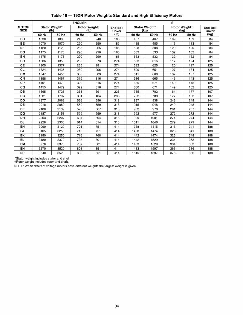
94
Table 16 — 19XR Motor Weights Standard and High Efficiency Motors
*Stator weight includes stator and shell.†Rotor weight includes rotor and shaft.NOTE: When different voltage motors have different weights the largest weight is given.
MOTORSIZE
ENGLISH SIStator Weight*
(lb)Rotor Weight†
(lb)End Bell
Cover(lb)
Stator Weight*(kg)
Rotor Weight†(kg)
End BellCover(kg)60 Hz 50 Hz 60 Hz 50 Hz 60 Hz 50 Hz 60 Hz 50 Hz
BD 1030 1030 240 240 185 467 467 109 109 84BE 1070 1070 250 250 185 485 485 113 113 84BF 1120 1120 265 265 185 508 508 120 120 84BG 1175 1175 290 290 185 533 533 132 132 84BH 1175 1175 290 290 185 533 533 132 132 84CD 1286 1358 258 273 274 583 616 117 124 125CE 1305 1377 265 281 274 592 625 120 127 125CL 1324 1435 280 296 274 600 651 127 134 125CM 1347 1455 303 303 274 611 660 137 137 125CN 1358 1467 316 316 274 616 665 143 143 125CP 1401 1479 329 316 274 635 671 149 143 125CQ 1455 1479 329 316 274 660 671 149 152 125DB 1665 1725 361 391 236 755 782 164 177 107DC 1681 1737 391 404 236 762 788 177 183 107DD 1977 2069 536 596 318 897 938 243 248 144DE 2018 2089 550 550 318 915 948 249 248 144DF 2100 2139 575 567 318 952 970 261 257 144DG 2187 2153 599 599 318 992 977 272 272 144DH 2203 2207 604 604 318 999 1001 274 274 144DJ 2228 2305 614 614 318 1011 1046 279 279 144EH 3060 3120 701 751 414 1388 1415 318 341 188EJ 3105 3250 716 751 414 1408 1474 325 341 188EK 3180 3250 716 768 414 1442 1474 325 348 188EL 3180 3370 737 801 414 1442 1529 334 363 188EM 3270 3370 737 801 414 1483 1529 334 363 188EN 3270 3520 801 851 414 1483 1597 363 386 188EP 3340 3520 830 851 414 1515 1597 376 386 188
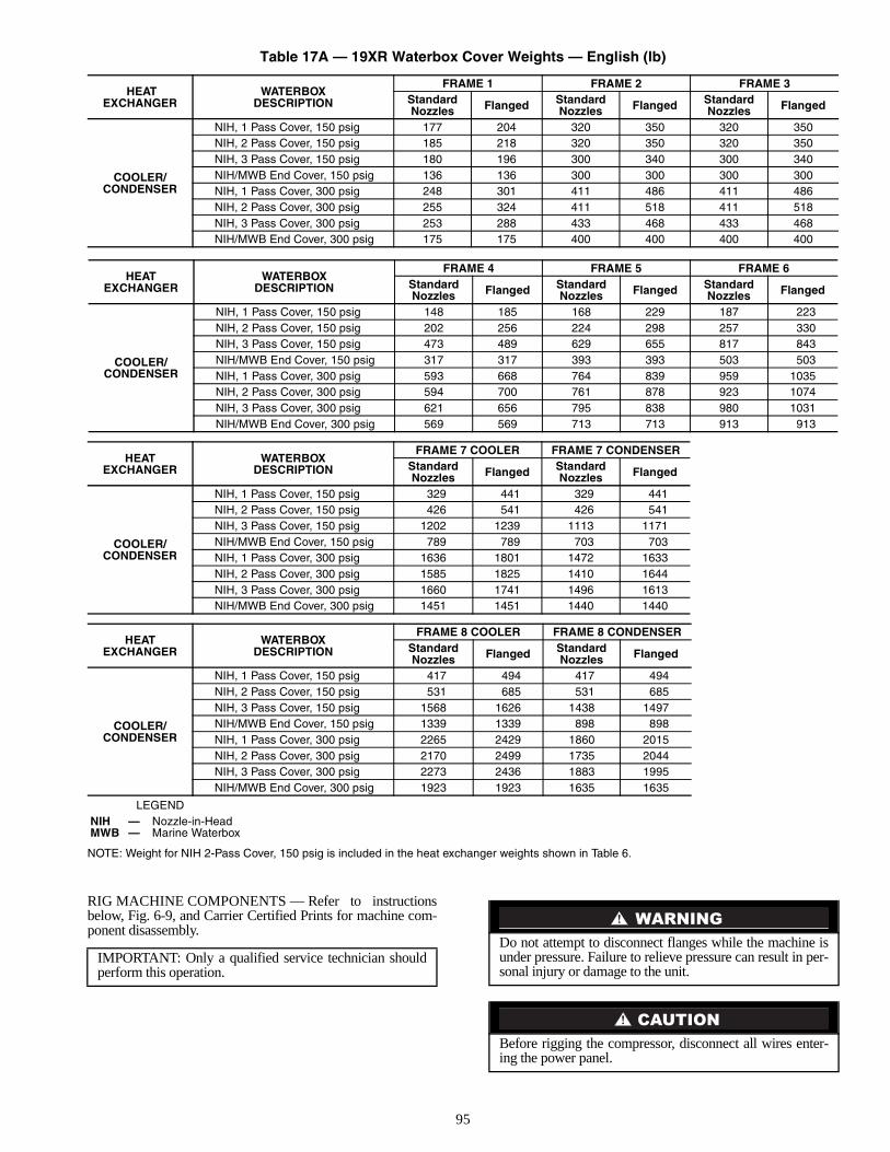
95
Table 17A — 19XR Waterbox Cover Weights — English (lb)
LEGEND
NOTE: Weight for NIH 2-Pass Cover, 150 psig is included in the heat exchanger weights shown in Table 6.
RIG MACHINE COMPONENTS — Refer to instructionsbelow, Fig. 6-9, and Carrier Certified Prints for machine com-ponent disassembly.
HEATEXCHANGER
WATERBOXDESCRIPTION
FRAME 1 FRAME 2 FRAME 3StandardNozzles Flanged Standard
Nozzles Flanged StandardNozzles Flanged
COOLER/CONDENSER
NIH, 1 Pass Cover, 150 psig 177 204 320 350 320 350NIH, 2 Pass Cover, 150 psig 185 218 320 350 320 350NIH, 3 Pass Cover, 150 psig 180 196 300 340 300 340NIH/MWB End Cover, 150 psig 136 136 300 300 300 300NIH, 1 Pass Cover, 300 psig 248 301 411 486 411 486NIH, 2 Pass Cover, 300 psig 255 324 411 518 411 518NIH, 3 Pass Cover, 300 psig 253 288 433 468 433 468NIH/MWB End Cover, 300 psig 175 175 400 400 400 400
HEATEXCHANGER
WATERBOXDESCRIPTION
FRAME 4 FRAME 5 FRAME 6StandardNozzles Flanged Standard
Nozzles Flanged StandardNozzles Flanged
COOLER/CONDENSER
NIH, 1 Pass Cover, 150 psig 148 185 168 229 187 223NIH, 2 Pass Cover, 150 psig 202 256 224 298 257 330NIH, 3 Pass Cover, 150 psig 473 489 629 655 817 843NIH/MWB End Cover, 150 psig 317 317 393 393 503 503NIH, 1 Pass Cover, 300 psig 593 668 764 839 959 1035NIH, 2 Pass Cover, 300 psig 594 700 761 878 923 1074NIH, 3 Pass Cover, 300 psig 621 656 795 838 980 1031NIH/MWB End Cover, 300 psig 569 569 713 713 913 913
HEATEXCHANGER
WATERBOXDESCRIPTION
FRAME 7 COOLER FRAME 7 CONDENSERStandardNozzles Flanged Standard
Nozzles Flanged
COOLER/CONDENSER
NIH, 1 Pass Cover, 150 psig 329 441 329 441NIH, 2 Pass Cover, 150 psig 426 541 426 541NIH, 3 Pass Cover, 150 psig 1202 1239 1113 1171NIH/MWB End Cover, 150 psig 789 789 703 703NIH, 1 Pass Cover, 300 psig 1636 1801 1472 1633NIH, 2 Pass Cover, 300 psig 1585 1825 1410 1644NIH, 3 Pass Cover, 300 psig 1660 1741 1496 1613NIH/MWB End Cover, 300 psig 1451 1451 1440 1440
HEATEXCHANGER
WATERBOXDESCRIPTION
FRAME 8 COOLER FRAME 8 CONDENSERStandardNozzles Flanged Standard
Nozzles Flanged
COOLER/CONDENSER
NIH, 1 Pass Cover, 150 psig 417 494 417 494NIH, 2 Pass Cover, 150 psig 531 685 531 685NIH, 3 Pass Cover, 150 psig 1568 1626 1438 1497NIH/MWB End Cover, 150 psig 1339 1339 898 898NIH, 1 Pass Cover, 300 psig 2265 2429 1860 2015NIH, 2 Pass Cover, 300 psig 2170 2499 1735 2044NIH, 3 Pass Cover, 300 psig 2273 2436 1883 1995NIH/MWB End Cover, 300 psig 1923 1923 1635 1635
NIH — Nozzle-in-HeadMWB — Marine Waterbox
IMPORTANT: Only a qualified service technician shouldperform this operation.
Do not attempt to disconnect flanges while the machine isunder pressure. Failure to relieve pressure can result in per-sonal injury or damage to the unit.
Before rigging the compressor, disconnect all wires enter-ing the power panel.
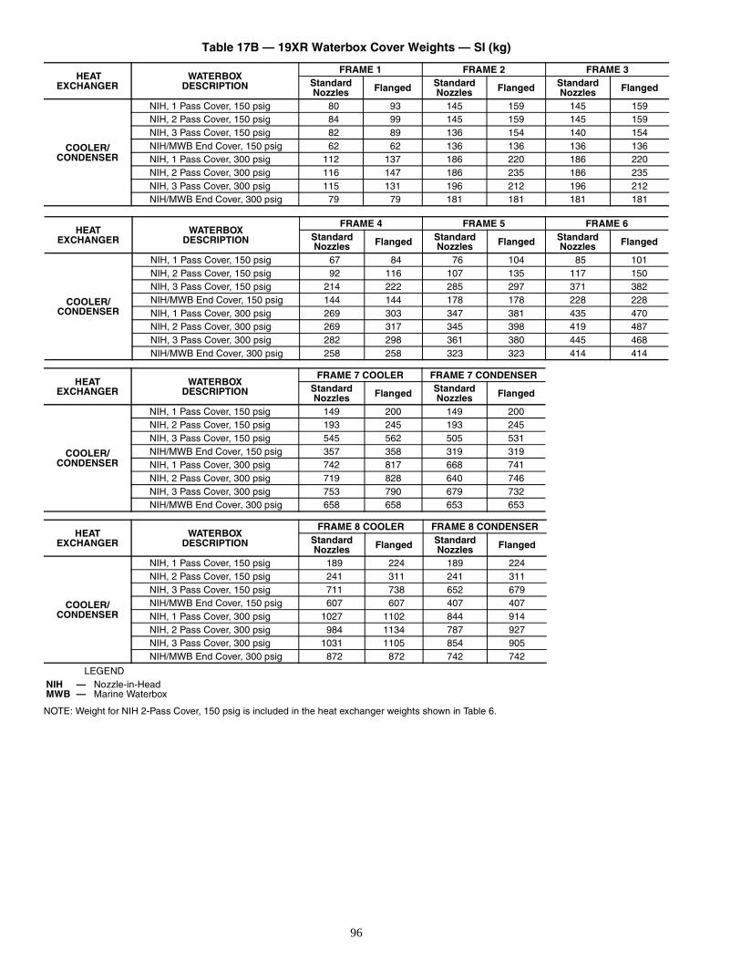
96
Table 17B — 19XR Waterbox Cover Weights — SI (kg)
LEGEND
NOTE: Weight for NIH 2-Pass Cover, 150 psig is included in the heat exchanger weights shown in Table 6.
HEATEXCHANGER
WATERBOXDESCRIPTION
FRAME 1 FRAME 2 FRAME 3StandardNozzles Flanged Standard
Nozzles Flanged StandardNozzles Flanged
COOLER/CONDENSER
NIH, 1 Pass Cover, 150 psig 80 93 145 159 145 159NIH, 2 Pass Cover, 150 psig 84 99 145 159 145 159NIH, 3 Pass Cover, 150 psig 82 89 136 154 140 154NIH/MWB End Cover, 150 psig 62 62 136 136 136 136NIH, 1 Pass Cover, 300 psig 112 137 186 220 186 220NIH, 2 Pass Cover, 300 psig 116 147 186 235 186 235NIH, 3 Pass Cover, 300 psig 115 131 196 212 196 212NIH/MWB End Cover, 300 psig 79 79 181 181 181 181
HEATEXCHANGER
WATERBOXDESCRIPTION
FRAME 4 FRAME 5 FRAME 6StandardNozzles Flanged Standard
Nozzles Flanged StandardNozzles Flanged
COOLER/CONDENSER
NIH, 1 Pass Cover, 150 psig 67 84 76 104 85 101NIH, 2 Pass Cover, 150 psig 92 116 107 135 117 150NIH, 3 Pass Cover, 150 psig 214 222 285 297 371 382NIH/MWB End Cover, 150 psig 144 144 178 178 228 228NIH, 1 Pass Cover, 300 psig 269 303 347 381 435 470NIH, 2 Pass Cover, 300 psig 269 317 345 398 419 487NIH, 3 Pass Cover, 300 psig 282 298 361 380 445 468NIH/MWB End Cover, 300 psig 258 258 323 323 414 414
HEATEXCHANGER
WATERBOXDESCRIPTION
FRAME 7 COOLER FRAME 7 CONDENSERStandardNozzles Flanged Standard
Nozzles Flanged
COOLER/CONDENSER
NIH, 1 Pass Cover, 150 psig 149 200 149 200NIH, 2 Pass Cover, 150 psig 193 245 193 245NIH, 3 Pass Cover, 150 psig 545 562 505 531NIH/MWB End Cover, 150 psig 357 358 319 319NIH, 1 Pass Cover, 300 psig 742 817 668 741NIH, 2 Pass Cover, 300 psig 719 828 640 746NIH, 3 Pass Cover, 300 psig 753 790 679 732NIH/MWB End Cover, 300 psig 658 658 653 653
HEATEXCHANGER
WATERBOXDESCRIPTION
FRAME 8 COOLER FRAME 8 CONDENSERStandardNozzles Flanged Standard
Nozzles Flanged
COOLER/CONDENSER
NIH, 1 Pass Cover, 150 psig 189 224 189 224NIH, 2 Pass Cover, 150 psig 241 311 241 311NIH, 3 Pass Cover, 150 psig 711 738 652 679NIH/MWB End Cover, 150 psig 607 607 407 407NIH, 1 Pass Cover, 300 psig 1027 1102 844 914NIH, 2 Pass Cover, 300 psig 984 1134 787 927NIH, 3 Pass Cover, 300 psig 1031 1105 854 905NIH/MWB End Cover, 300 psig 872 872 742 742
NIH — Nozzle-in-HeadMWB — Marine Waterbox
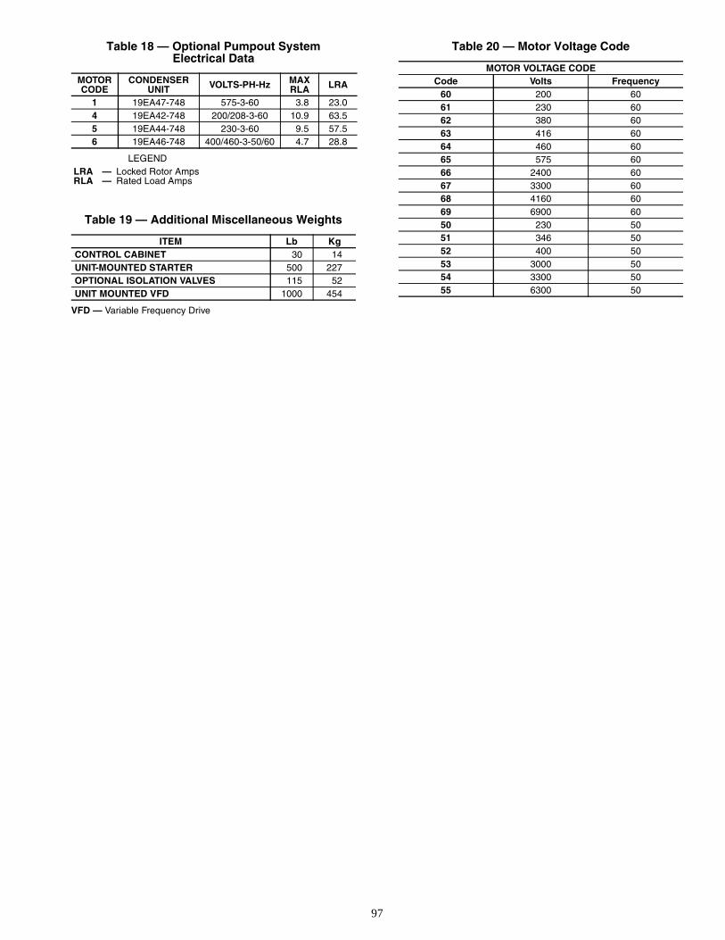
97
Table 18 — Optional Pumpout SystemElectrical Data
LEGEND
Table 19 — Additional Miscellaneous Weights
VFD — Variable Frequency Drive
Table 20 — Motor Voltage Code
MOTORCODE
CONDENSERUNIT VOLTS-PH-Hz MAX
RLA LRA
1 19EA47-748 575-3-60 3.8 23.04 19EA42-748 200/208-3-60 10.9 63.55 19EA44-748 230-3-60 9.5 57.56 19EA46-748 400/460-3-50/60 4.7 28.8
LRA — Locked Rotor AmpsRLA — Rated Load Amps
ITEM Lb KgCONTROL CABINET 30 14UNIT-MOUNTED STARTER 500 227OPTIONAL ISOLATION VALVES 115 52UNIT MOUNTED VFD 1000 454
MOTOR VOLTAGE CODECode Volts Frequency
60 200 6061 230 6062 380 6063 416 6064 460 6065 575 6066 2400 6067 3300 6068 4160 6069 6900 6050 230 5051 346 5052 400 5053 3000 5054 3300 5055 6300 50
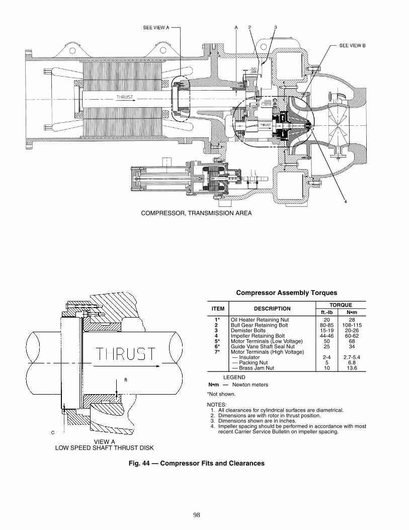
98
Compressor Assembly Torques
LEGEND
*Not shown.
NOTES:1. All clearances for cylindrical surfaces are diametrical.2. Dimensions are with rotor in thrust position.3. Dimensions shown are in inches.4. Impeller spacing should be performed in accordance with most
recent Carrier Service Bulletin on impeller spacing.
ITEM DESCRIPTIONTORQUE
ft.-lb N•m1* Oil Heater Retaining Nut 20 282 Bull Gear Retaining Bolt 80-85 108-1153 Demister Bolts 15-19 20-264 Impeller Retaining Bolt 44-46 60-625* Motor Terminals (Low Voltage) 50 686* Guide Vane Shaft Seal Nut 25 347* Motor Terminals (High Voltage)
— Insulator 2-4 2.7-5.4 — Packing Nut 5 6.8 — Brass Jam Nut 10 13.6
N•m — Newton meters
VIEW ALOW SPEED SHAFT THRUST DISK
Fig. 44 — Compressor Fits and Clearances
COMPRESSOR, TRANSMISSION AREA
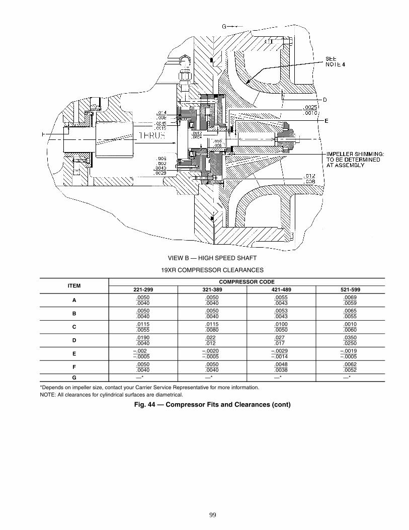
99
VIEW B — HIGH SPEED SHAFT
19XR COMPRESSOR CLEARANCES
*Depends on impeller size, contact your Carrier Service Representative for more information.NOTE: All clearances for cylindrical surfaces are diametrical.
Fig. 44 — Compressor Fits and Clearances (cont)
ITEMCOMPRESSOR CODE
221-299 321-389 421-489 521-599
A .0050.0040
.0050
.0040.0055.0043
.0069
.0059
B .0050.0040
.0050
.0040.0053.0043
.0065
.0055
C .0115.0055
.0115
.0080.0100.0050
.0010
.0060
D .0190.0040
.022
.012.027.017
.0350
.0250
E –.002–.0005
–.0020–.0005
–.0029–.0014
–.0019–.0005
F .0050.0040
.0050
.0040.0048.0038
.0062
.0052
G —* —* —* —*
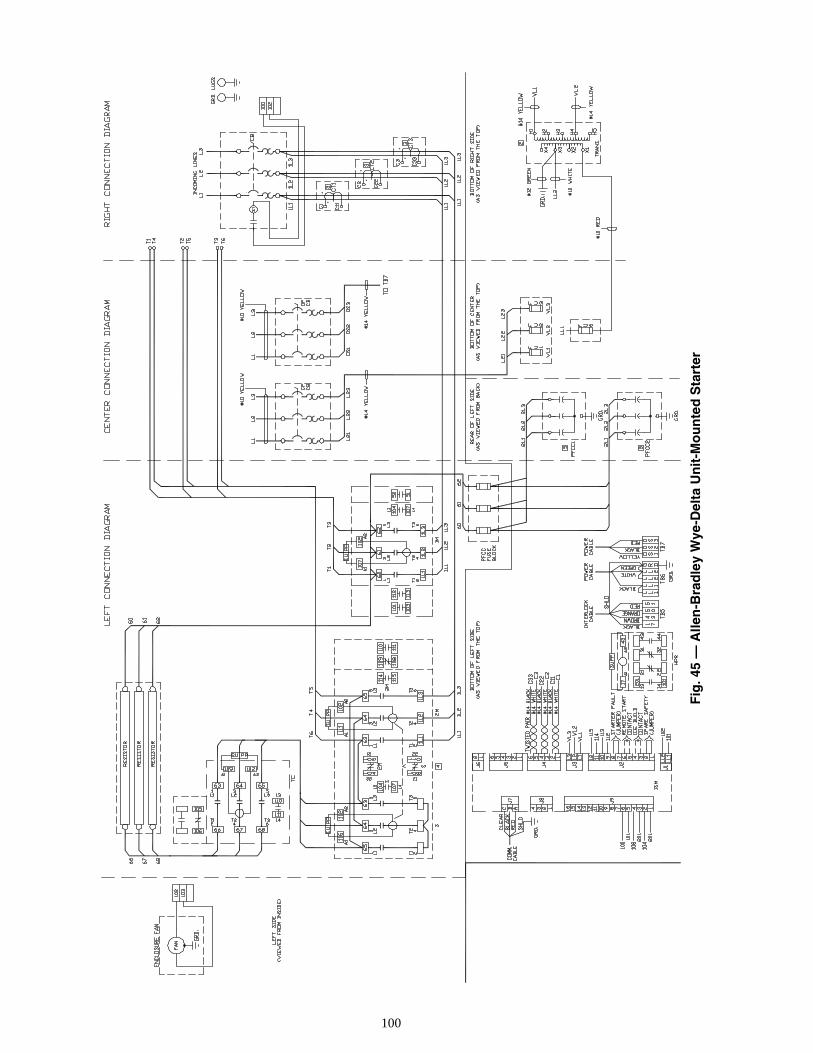
100
Fig
. 45
— A
llen
-Bra
dle
y W
ye-D
elta
Un
it-M
ou
nte
d S
tart
er
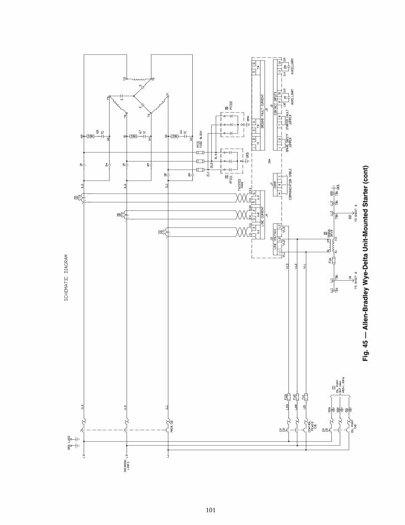
101
Fig
. 45
— A
llen
-Bra
dle
y W
ye-D
elta
Un
it-M
ou
nte
d S
tart
er (
con
t)
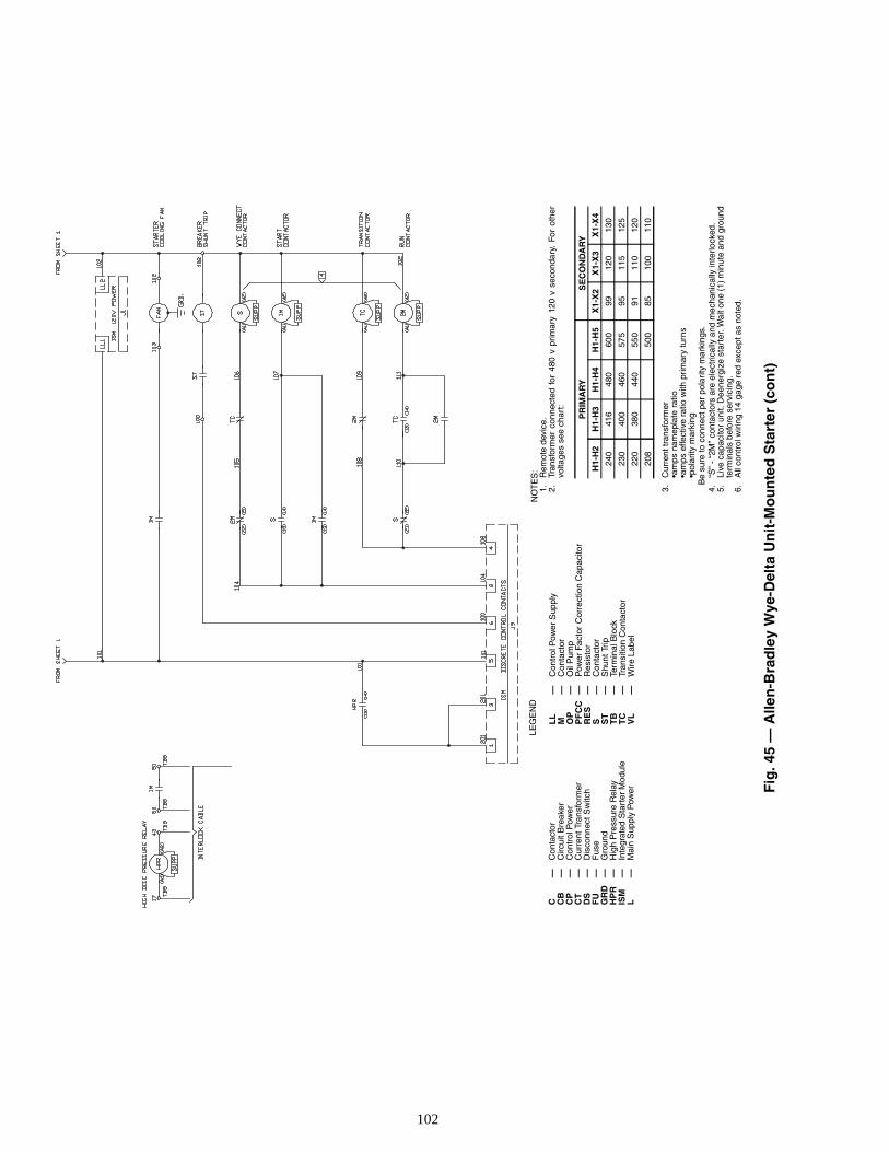
102
Fig
. 45
— A
llen
-Bra
dle
y W
ye-D
elta
Un
it-M
ou
nte
d S
tart
er (
con
t)
C—
Con
tact
orC
B—
Circ
uit B
reak
erC
P—
Con
trol
Pow
erC
T—
Cur
rent
Tra
nsfo
rmer
DS
—D
isco
nnec
t Sw
itch
FU
—F
use
GR
D—
Gro
und
HP
R—
Hig
h P
ress
ure
Rel
ayIS
M—
Inte
grat
ed S
tart
er M
odul
eL
—M
ain
Sup
ply
Pow
er
L
L—
Con
trol
Pow
er S
uppl
yM
—C
onta
ctor
OP
—O
il P
ump
PF
CC
—P
ower
Fac
tor
Cor
rect
ion
Cap
acito
rR
ES
—R
esis
tor
S—
Con
tact
orS
T—
Shu
nt T
rip
TB
—Te
rmin
al B
lock
TC
—Tr
ansi
tion
Con
tact
orV
L—
Wire
Lab
el
LEG
EN
DN
OT
ES
:1.
Rem
ote
devi
ce.
2.Tr
ansf
orm
er c
onne
cted
for
480
v p
rim
ary
120
v se
cond
ary.
For
oth
ervo
ltage
s se
e ch
art:
3.C
urre
nt tr
ansf
orm
er•a
mps
nam
epla
te r
atio
•am
ps e
ffect
ive
ratio
with
pri
mar
y tu
rns
•pol
arity
mar
king
Be
sure
to c
onne
ct p
er p
olar
ity m
arki
ngs.
4.“S
” -
“2M
” co
ntac
tors
are
ele
ctric
ally
and
mec
hani
cally
inte
rlock
ed.
5.Li
ve c
apac
itor
unit.
Dee
nerg
ize
star
ter.
Wai
t one
(1)
min
ute
and
grou
ndte
rmin
als
befo
re s
ervi
cing
.6.
All
cont
rol w
irin
g 14
gag
e re
d ex
cept
as
note
d.
PR
IMA
RY
SE
CO
ND
AR
Y
H1-
H2
H1-
H3
H1-
H4
H1-
H5
X1-
X2
X1-
X3
X1-
X4
240
416
480
600
9912
013
0
230
400
460
575
9511
512
5
220
380
440
550
9111
012
0
208
500
8510
011
0
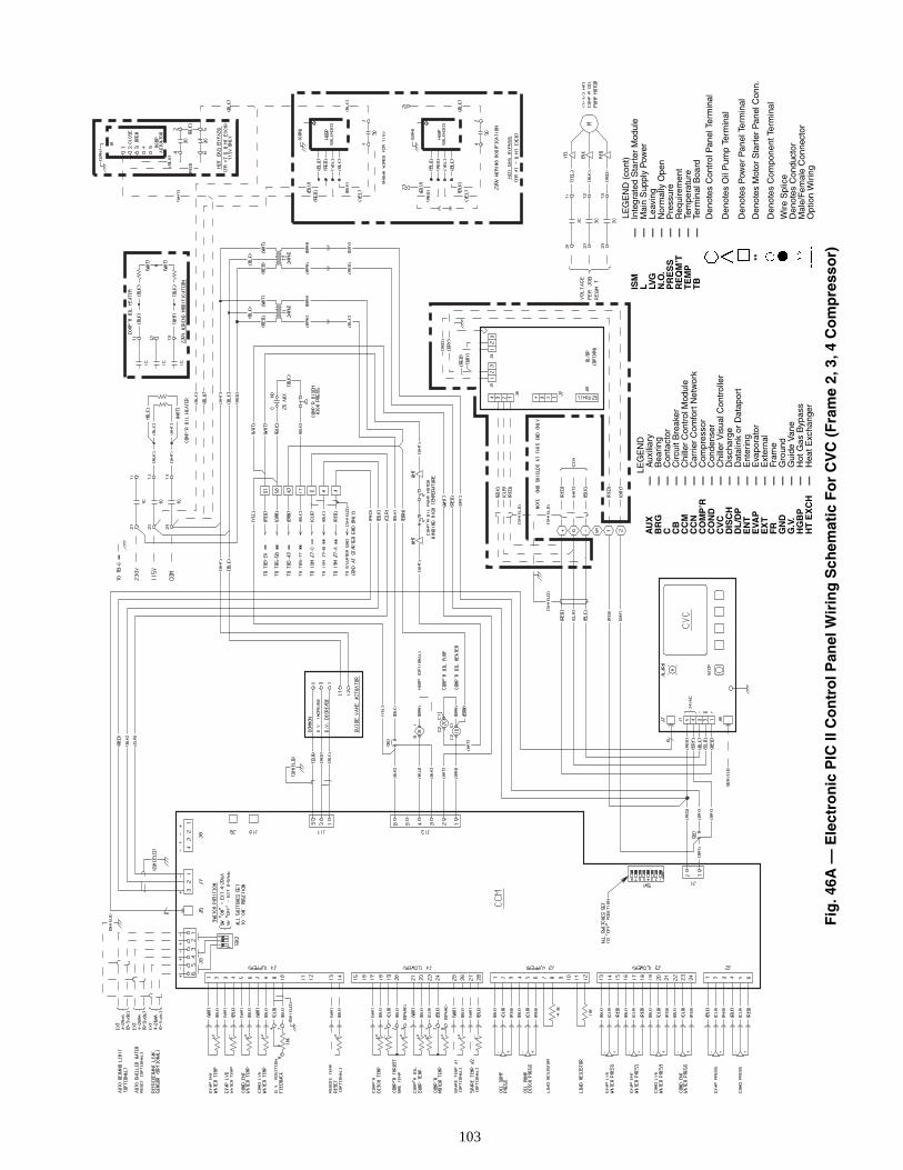
103
LE
GE
ND
AU
X—
Aux
iliar
yB
RG
—B
earin
gC
—C
onta
ctor
CB
—C
ircui
t Bre
aker
CC
M—
Chi
ller
Con
trol
Mod
ule
CC
N—
Car
rier
Com
fort
Net
wor
kC
OM
P’R
—C
ompr
esso
rC
ON
D—
Con
dens
erC
VC
—C
hille
r V
isua
l Con
trol
ler
DIS
CH
—D
isch
arge
DL
/DP
—D
atal
ink
or D
atap
ort
EN
T—
Ent
erin
gE
VAP
—E
vapo
rato
rE
XT
—E
xter
nal
FR
—Fr
ame
GN
D—
Gro
und
G.V
.—
Gui
de V
ane
HG
BP
—H
ot G
as B
ypas
sH
T E
XC
H—
Hea
t Exc
hang
er
LEG
EN
D (
cont
)IS
M—
Inte
grat
ed S
tart
er M
odul
eL
—M
ain
Sup
ply
Pow
erLV
G—
Leav
ing
N.O
.—
Nor
mal
ly O
pen
PR
ES
S—
Pre
ssur
eR
EQ
M’T
—R
equi
rem
ent
TE
MP
—Te
mpe
ratu
reT
B—
Term
inal
Boa
rdD
enot
es C
ontr
ol P
anel
Ter
min
al
Den
otes
Oil
Pum
p Te
rmin
al
Den
otes
Pow
er P
anel
Ter
min
al
**D
enot
es M
otor
Sta
rter
Pan
el C
onn.
Den
otes
Com
pone
nt T
erm
inal
Wire
Spl
ice
Den
otes
Con
duct
orM
ale/
Fem
ale
Con
nect
orO
ptio
n W
iring
Fig
. 46A
— E
lect
ron
ic P
IC II
Co
ntr
ol P
anel
Wir
ing
Sch
emat
ic F
or
CV
C (
Fra
me
2, 3
, 4 C
om
pre
sso
r)
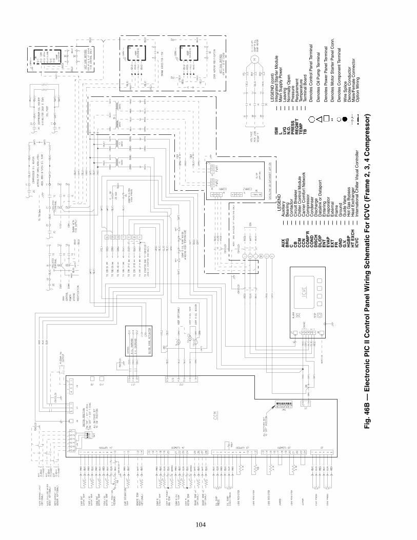
104
LE
GE
ND
AU
X—
Aux
iliar
yB
RG
—B
eari
ngC
—C
onta
ctor
CB
—C
ircui
t Bre
aker
CC
M—
Chi
ller
Con
trol
Mod
ule
CC
N—
Car
rier
Com
fort
Net
wor
kC
OM
P’R
—C
ompr
esso
rC
ON
D—
Con
dens
erD
ISC
H—
Dis
char
geD
L/D
P—
Dat
alin
k or
Dat
apor
tE
NT
—E
nter
ing
EVA
P—
Eva
pora
tor
EX
T—
Ext
erna
lF
R—
Fram
eG
ND
—G
roun
dG
.V.
—G
uide
Van
eH
GB
P—
Hot
Gas
Byp
ass
HT
EX
CH
—H
eat E
xcha
nger
ICV
C—
Inte
rnat
iona
l Chi
ller
Vis
ual C
ontr
olle
r
LEG
EN
D (
cont
)IS
M—
Inte
grat
ed S
tart
er M
odul
eL
—M
ain
Sup
ply
Pow
erLV
G—
Leav
ing
N.O
.—
Nor
mal
ly O
pen
PR
ES
S—
Pre
ssur
eR
EQ
M’T
—R
equi
rem
ent
TE
MP
—Te
mpe
ratu
reT
B—
Term
inal
Boa
rdD
enot
es C
ontr
ol P
anel
Ter
min
al
Den
otes
Oil
Pum
p Te
rmin
al
Den
otes
Pow
er P
anel
Ter
min
al
**D
enot
es M
otor
Sta
rter
Pan
el C
onn.
Den
otes
Com
pone
nt T
erm
inal
Wire
Spl
ice
Den
otes
Con
duct
orM
ale/
Fem
ale
Con
nect
orO
ptio
n W
irin
g
Fig
. 46B
— E
lect
ron
ic P
IC II
Co
ntr
ol P
anel
Wir
ing
Sch
emat
ic F
or
ICV
C (
Fra
me
2, 3
, 4 C
om
pre
sso
r)
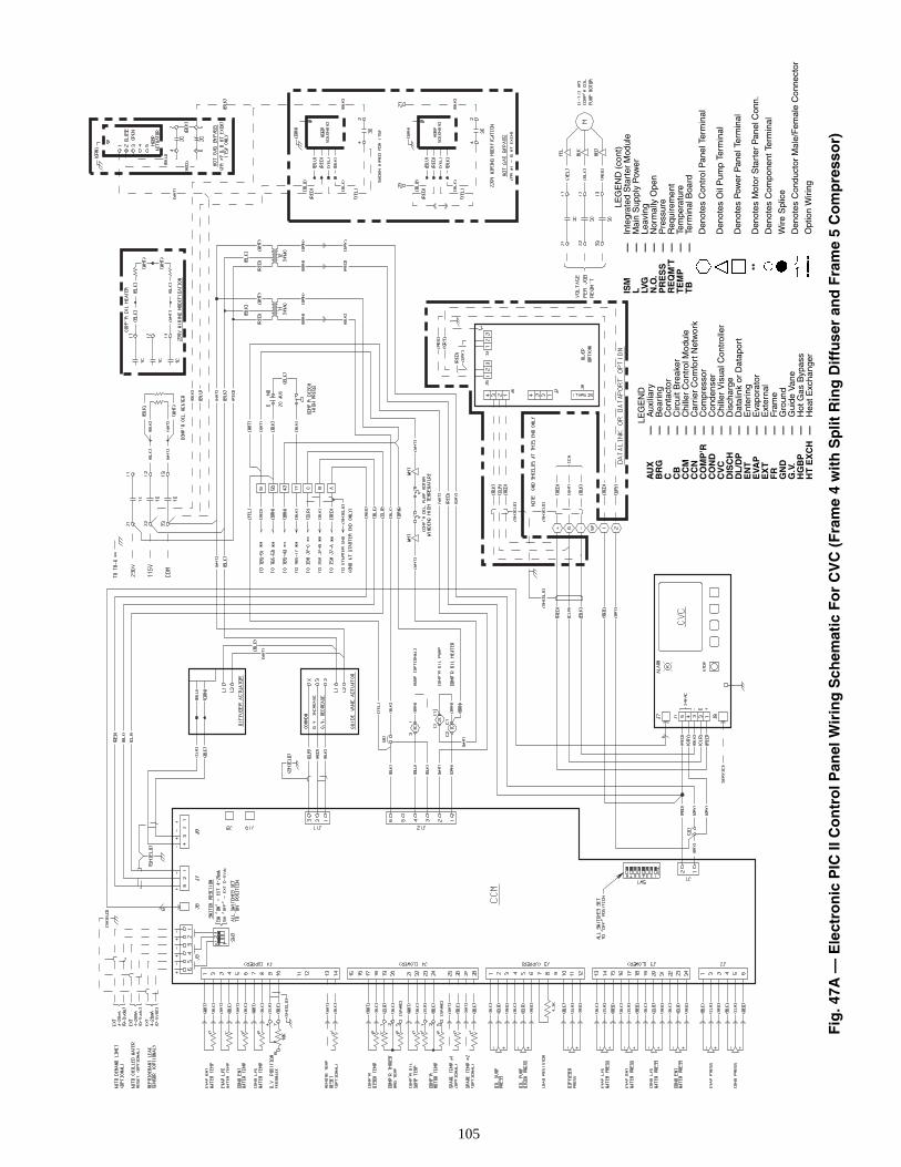
105
LEG
EN
DA
UX
—A
uxili
ary
BR
G—
Bea
ring
C—
Con
tact
orC
B—
Circ
uit B
reak
erC
CM
—C
hille
r C
ontr
ol M
odul
eC
CN
—C
arri
er C
omfo
rt N
etw
ork
CO
MP
’R—
Com
pres
sor
CO
ND
—C
onde
nser
CV
C—
Chi
ller
Vis
ual C
ontr
olle
rD
ISC
H—
Dis
char
geD
L/D
P—
Dat
alin
k or
Dat
apor
tE
NT
—E
nter
ing
EVA
P—
Eva
pora
tor
EX
T—
Ext
erna
lF
R—
Fram
eG
ND
—G
roun
dG
.V.
—G
uide
Van
eH
GB
P—
Hot
Gas
Byp
ass
HT
EX
CH
—H
eat E
xcha
nger
LEG
EN
D (
cont
)IS
M—
Inte
grat
ed S
tart
er M
odul
eL
—M
ain
Sup
ply
Pow
erLV
G—
Leav
ing
N.O
.—
Nor
mal
ly O
pen
PR
ES
S—
Pre
ssur
eR
EQ
M’T
—R
equi
rem
ent
TE
MP
—Te
mpe
ratu
reT
B—
Term
inal
Boa
rd
Den
otes
Con
trol
Pan
el T
erm
inal
Den
otes
Oil
Pum
p Te
rmin
al
Den
otes
Pow
er P
anel
Ter
min
al
**D
enot
es M
otor
Sta
rter
Pan
el C
onn.
Den
otes
Com
pone
nt T
erm
inal
Wire
Spl
ice
Den
otes
Con
duct
or M
ale/
Fem
ale
Con
nect
or
Opt
ion
Wiri
ng
Fig
. 47A
— E
lect
ron
ic P
IC II
Co
ntr
ol P
anel
Wir
ing
Sch
emat
ic F
or
CV
C (
Fra
me
4 w
ith
Sp
lit R
ing
Dif
fuse
r an
d F
ram
e 5
Co
mp
ress
or)
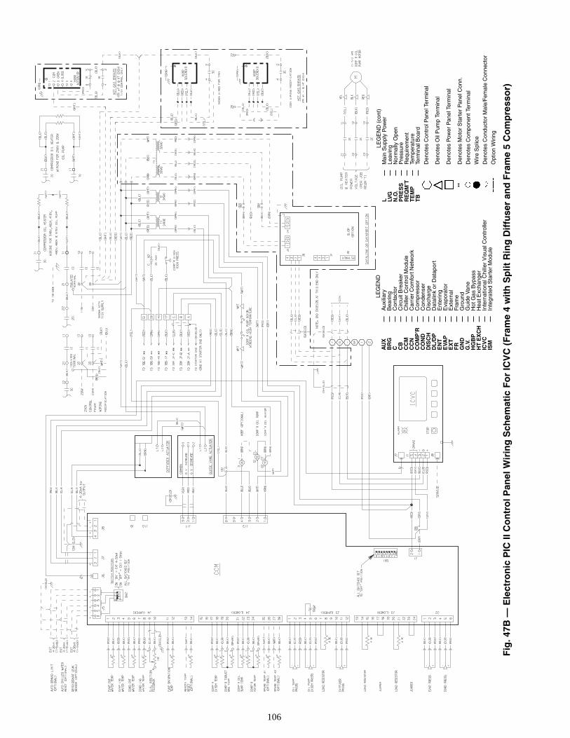
106
LE
GE
ND
AU
X—
Aux
iliar
yB
RG
—B
earin
gC
—C
onta
ctor
CB
—C
ircui
t Bre
aker
CC
M—
Chi
ller
Con
trol
Mod
ule
CC
N—
Car
rier
Com
fort
Net
wor
kC
OM
P’R
—C
ompr
esso
rC
ON
D—
Con
dens
erD
ISC
H—
Dis
char
geD
L/D
P—
Dat
alin
k or
Dat
apor
tE
NT
—E
nter
ing
EVA
P—
Eva
pora
tor
EX
T—
Ext
erna
lF
R—
Fram
eG
ND
—G
roun
dG
.V.
—G
uide
Van
eH
GB
P—
Hot
Gas
Byp
ass
HT
EX
CH
—H
eat E
xcha
nger
ICV
C—
Inte
rnat
iona
l Chi
ller
Vis
ual C
ontr
olle
rIS
M—
Inte
grat
ed S
tart
er M
odul
e
LEG
EN
D (
cont
)L
—M
ain
Sup
ply
Pow
erLV
G—
Leav
ing
N.O
.—
Nor
mal
ly O
pen
PR
ES
S—
Pre
ssur
eR
EQ
M’T
—R
equi
rem
ent
TE
MP
—Te
mpe
ratu
reT
B—
Term
inal
Boa
rd
Den
otes
Con
trol
Pan
el T
erm
inal
Den
otes
Oil
Pum
p Te
rmin
al
Den
otes
Pow
er P
anel
Ter
min
al
**D
enot
es M
otor
Sta
rter
Pan
el C
onn.
Den
otes
Com
pone
nt T
erm
inal
Wire
Spl
ice
Den
otes
Con
duct
or M
ale/
Fem
ale
Con
nect
or
Opt
ion
Wir
ing
Fig
. 47B
— E
lect
ron
ic P
IC II
Co
ntr
ol P
anel
Wir
ing
Sch
emat
ic F
or
ICV
C (
Fra
me
4 w
ith
Sp
lit R
ing
Dif
fuse
r an
d F
ram
e 5
Co
mp
ress
or)
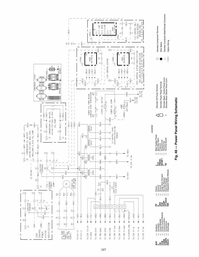
107
A
UX
—A
uxili
ary
C—
Con
tact
orC
B—
Circ
uit B
reak
erC
CM
—C
hille
r C
ontr
ol M
odul
eC
OM
M—
Com
mun
icat
ion
CO
MP
R—
Com
pres
sor
DIS
CH
—D
isch
arge
Den
otes
Oil
Pum
p Te
rmin
al
Den
otes
Pow
er P
anel
Ter
min
al
*D
enot
es M
ach.
Con
trol
Pan
el C
onn.
**D
enot
es M
otor
Sta
rter
Pan
el C
onn.
Fig
. 48
— P
ow
er P
anel
Wir
ing
Sch
emat
ic
FR
—Fr
ame
G—
Gro
und
GR
D—
Gro
und
GVA
—G
uide
Van
e A
ctua
tor
HG
BP
—H
ot G
as B
ypas
sH
T E
XC
H—
Hea
t Exc
hang
erIS
M—
Inte
grat
ed S
tart
er M
odul
e
L
—M
ain
Sup
ply
Pow
erN
.O.
—N
orm
ally
Ope
nP
RE
SS
—P
ress
ure
RE
QM
’T—
Req
uire
men
tT
—Tr
ansf
orm
erT
B—
Term
inal
Boa
rd
Den
otes
Com
pone
nt T
erm
inal
Wire
Spl
ice
Den
otes
Con
duct
or M
ale/
Fem
ale
Con
nect
or
Opt
ion
Wir
ing
LEG
EN
D
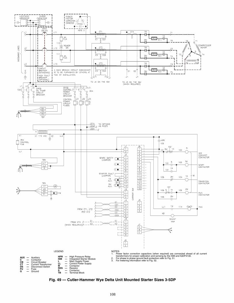
108
AUX — AuxiliaryC — ContactorCB — Circuit BreakerCT — Current TransformerDS — Disconnect SwitchFU — FuseG — Ground
Fig. 49 — Cutler-Hammer Wye Delta Unit Mounted Starter Sizes 3-5DP
HPR — High Pressure RelayISM — Integrated Starter ModuleL — Main Supply PowerLL — Control Power SupplyM — ContactorRES — ResistorS — ContactorTB — Terminal Block
LEGEND NOTES:1. Power factor correction capacitors (when required) are connected ahead of all current
transformers for proper calibration and sensing by the ISM and IQDP4130.2. For phase to phase ground fault protection refer to Fig. 51.3. For metering information refer to Fig. 52.
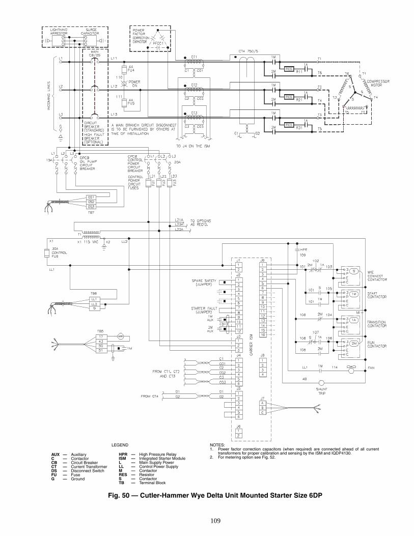
109
AUX — AuxiliaryC — ContactorCB — Circuit BreakerCT — Current TransformerDS — Disconnect SwitchFU — FuseG — Ground
Fig. 50 — Cutler-Hammer Wye Delta Unit Mounted Starter Size 6DP
HPR — High Pressure RelayISM — Integrated Starter ModuleL — Main Supply PowerLL — Control Power SupplyM — ContactorRES — ResistorS — ContactorTB — Terminal Block
LEGEND NOTES:1. Power factor correction capacitors (when required) are connected ahead of all current
transformers for proper calibration and sensing by the ISM and IQDP4130.2. For metering option see Fig. 52.
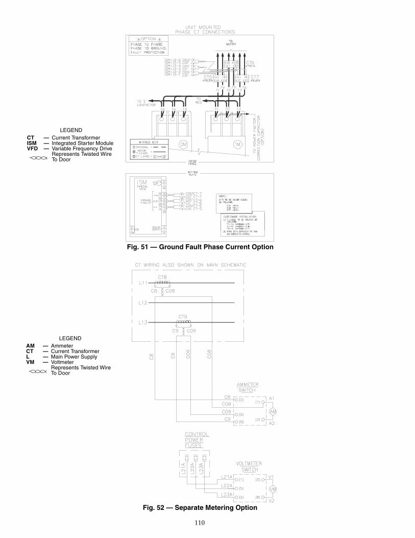
110
Fig. 51 — Ground Fault Phase Current Option
Fig. 52 — Separate Metering Option
LEGENDAM — AmmeterCT — Current TransformerL — Main Power SupplyVM — Voltmeter
Represents Twisted Wire To Door
LEGENDCT — Current TransformerISM — Integrated Starter ModuleVFD — Variable Frequency Drive
Represents Twisted Wire To Door
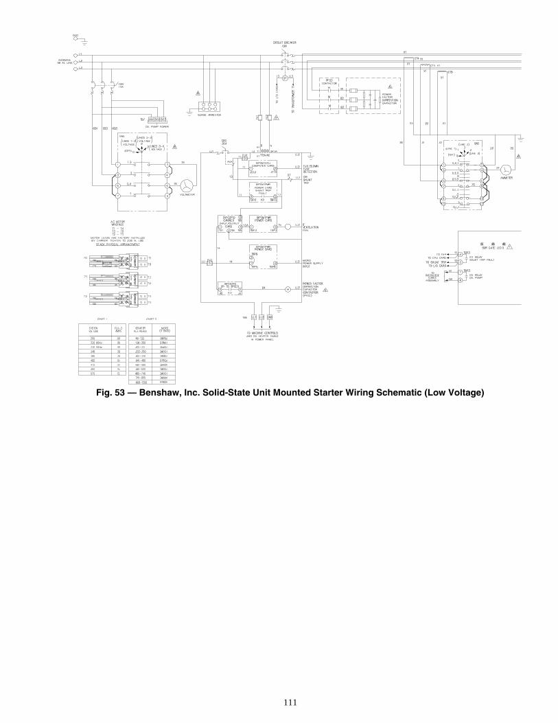
111
Fig. 53 — Benshaw, Inc. Solid-State Unit Mounted Starter Wiring Schematic (Low Voltage)
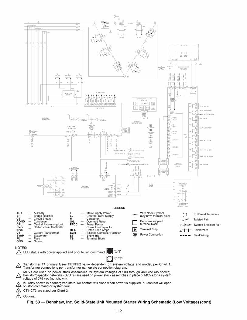
112
Fig. 53 — Benshaw, Inc. Solid-State Unit Mounted Starter Wiring Schematic (Low Voltage) (cont)
AUX — AuxiliaryBR — Bridge RectifierCB — Circuit BreakerCOND — CondenserCPU — Central Processing UnitCVC/ICVC — Chiller Visual Controller
CT — Current TransformerEVAP — EvaporatorFU — FuseGND — Ground
L — Main Supply PowerLL — Control Power SupplyM — ContactorO/L — Overload ResetPFCC — Power Factor
Correction CapacitorRLA — Rated Load AmpsSCR — Silicone Controller RectifierST — Shunt TripTB — Terminal Block
Wire Node Symbolmay have terminal block
Benshaw suppliedterminal block
Terminal Strip
Power Connection
PC Board Terminals
Twisted Pair
Twisted Shielded Pair
Shield Wire
Field Wiring
LEGEND
NOTES:LED status with power applied and prior to run command.
Transformer T1 primary fuses FU1/FU2 value dependent on system voltage and model, per Chart 1.Transformer connections per transformer nameplate connection diagram.MOVs are used on power stack assemblies for system voltages of 200 through 460 vac (as shown).Resistor/capacitor networks (DVDTs) are used on power stack assemblies in place of MOVs for a systemvoltage of 575 vac (not shown).K3 relay shown in deenergized state. K3 contact will close when power is supplied. K3 contact will openon stop command or system fault.CT1-CT3 are sized per Chart 2.
Optional.
1 "ON"
"OFF"
2
3
4
5
6
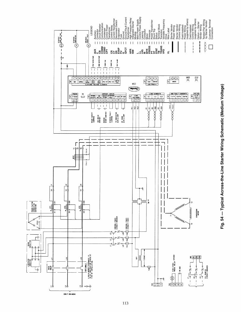
113
Fig
. 54
— T
ypic
al A
cro
ss-t
he-
Lin
e S
tart
er W
irin
g S
chem
atic
(M
ediu
m V
olt
age)
L
EG
EN
D
AU
X—
Aux
iliar
yC
—C
onta
ctor
CB
—C
ircui
t Bre
aker
CO
MM
—C
omm
unic
atio
nC
ON
D—
Con
dens
erC
PT
—C
ontr
ol P
ower
Tran
sfor
mer
CR
—C
ontr
ol R
elay
CT
—C
urre
nt T
rans
form
erD
S—
Dis
conn
ect S
witc
hE
VAP
—E
vapo
rato
rF
U—
Fus
eG
—G
roun
dG
FC
T—
Gro
und
Faul
t Cur
rent
Tran
sfor
mer
HP
R—
Hig
h P
ress
ure
Rel
ayIS
M—
Inte
grat
ed S
tart
erM
odul
eL
—M
ain
Pow
er S
uppl
yL
L—
Con
trol
Pow
er S
uppl
yLV
G—
Leav
ing
M—
Con
tact
orM
TR
—M
otor
PR
ES
S—
Pre
ssur
eP
T—
Pow
er T
rans
form
erS
T—
Shu
nt T
rip
STA
T—
Sta
tus
TB
—Te
rmin
al B
lock
TR
AN
S—
Tran
sitio
nV
FD
—V
aria
ble
Freq
uenc
yD
rive
VL
—W
ire L
abel
Sta
rter
Ven
dor
Pow
er W
iring
Sta
rter
Ven
dor
Con
trol
Wir
ing
Fie
ld In
stal
led
Pow
er W
iring
(sup
plie
d by
oth
ers)
Fie
ld In
stal
led
Con
trol
Wir
ing
(sup
plie
d by
oth
ers)
Opt
ion
— S
tart
erV
endo
r W
iring
Twis
ted
Pai
r W
irin
g b
y S
tart
er V
endo
r
Cus
tom
er T
erm
inal
Con
nect
ion
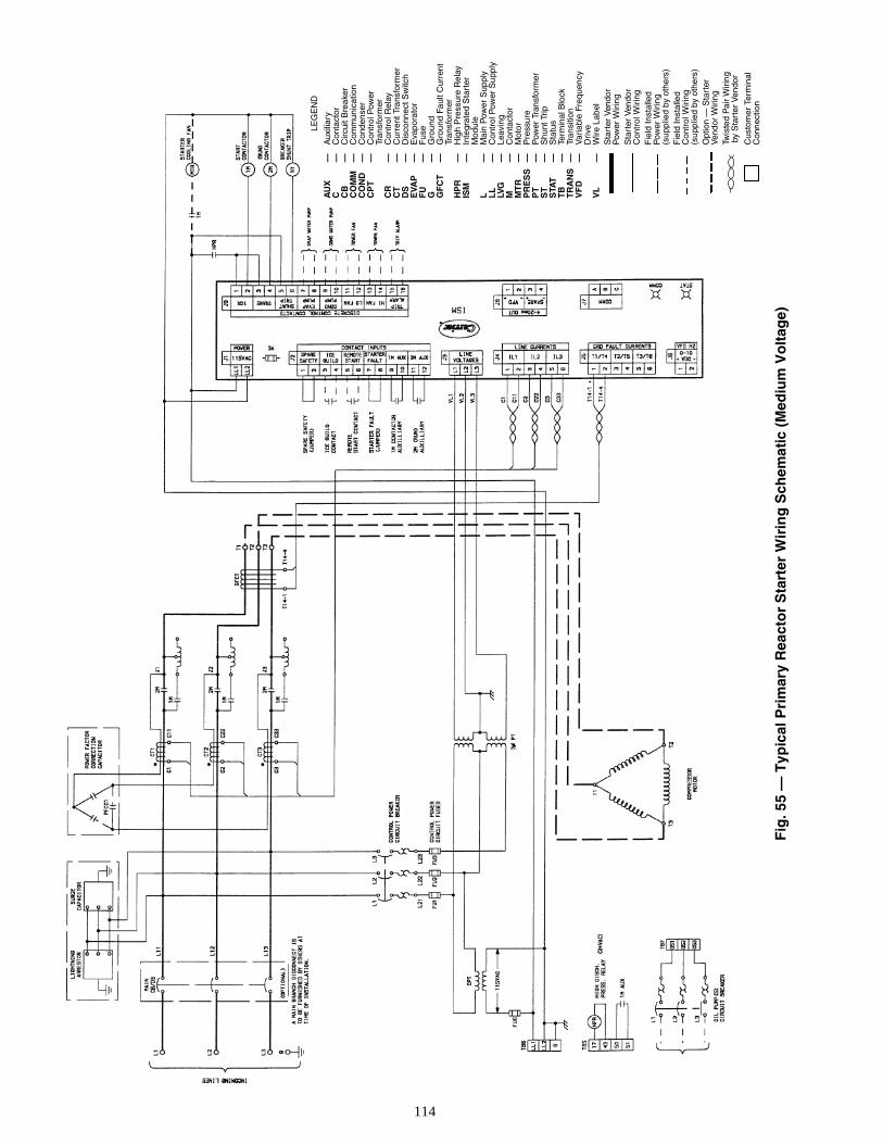
114
Fig
. 55
— T
ypic
al P
rim
ary
Rea
cto
r S
tart
er W
irin
g S
chem
atic
(M
ediu
m V
olt
age)
L
EG
EN
D
AU
X—
Aux
iliar
yC
—C
onta
ctor
CB
—C
ircui
t Bre
aker
CO
MM
—C
omm
unic
atio
nC
ON
D—
Con
dens
erC
PT
—C
ontr
ol P
ower
Tran
sfor
mer
CR
—C
ontr
ol R
elay
CT
—C
urre
nt T
rans
form
erD
S—
Dis
conn
ect S
witc
hE
VAP
—E
vapo
rato
rF
U—
Fus
eG
—G
roun
dG
FC
T—
Gro
und
Faul
t Cur
rent
Tran
sfor
mer
HP
R—
Hig
h P
ress
ure
Rel
ayIS
M—
Inte
grat
ed S
tart
erM
odul
eL
—M
ain
Pow
er S
uppl
yL
L—
Con
trol
Pow
er S
uppl
yLV
G—
Leav
ing
M—
Con
tact
orM
TR
—M
otor
PR
ES
S—
Pre
ssur
eP
T—
Pow
er T
rans
form
erS
T—
Shu
nt T
ripS
TAT
—S
tatu
sT
B—
Term
inal
Blo
ckT
RA
NS
—Tr
ansi
tion
VF
D—
Var
iabl
e Fr
eque
ncy
Driv
eV
L—
Wire
Lab
elS
tart
er V
endo
rP
ower
Wir
ing
Sta
rter
Ven
dor
Con
trol
Wiri
ngF
ield
Inst
alle
dP
ower
Wir
ing
(sup
plie
d by
oth
ers)
Fie
ld In
stal
led
Con
trol
Wiri
ng(s
uppl
ied
by o
ther
s)O
ptio
n —
Sta
rter
Ven
dor
Wir
ing
Twis
ted
Pai
r W
iring
by
Sta
rter
Ven
dor
Cus
tom
er T
erm
inal
Con
nect
ion
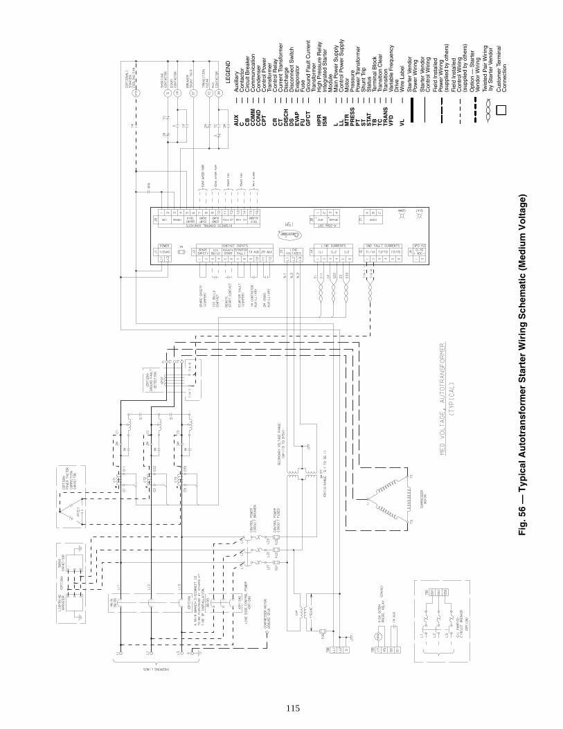
115
1A
Fig
. 56
— T
ypic
al A
uto
tran
sfo
rmer
Sta
rter
Wir
ing
Sch
emat
ic (
Med
ium
Vo
ltag
e)
L
EG
EN
D
AU
X—
Aux
iliar
yC
—C
onta
ctor
CB
—C
ircui
t Bre
aker
CO
MM
—C
omm
unic
atio
nC
ON
D—
Con
dens
erC
PT
—C
ontr
ol P
ower
Tran
sfor
mer
CR
—C
ontr
ol R
elay
CT
—C
urre
nt T
rans
form
erD
ISC
H—
Dis
char
geD
S—
Dis
conn
ect S
witc
hE
VAP
—E
vapo
rato
rF
U—
Fus
eG
FC
T—
Gro
und
Faul
t Cur
rent
Tran
sfor
mer
HP
R—
Hig
h P
ress
ure
Rel
ayIS
M—
Inte
grat
ed S
tart
erM
odul
eL
—M
ain
Pow
er S
uppl
yL
L—
Con
trol
Pow
er S
uppl
yM
TR
—M
otor
PR
ES
S—
Pre
ssur
eP
T—
Pow
er T
rans
form
erS
T—
Shu
nt T
ripS
TAT
—S
tatu
sT
B—
Term
inal
Blo
ckT
C—
Tran
sitio
n C
lear
TR
AN
S—
Tran
sitio
nV
FD
—V
aria
ble
Freq
uenc
yD
rive
VL
—W
ire L
abel
Sta
rter
Ven
dor
Pow
er W
irin
gS
tart
er V
endo
rC
ontr
ol W
iring
Fie
ld In
stal
led
Pow
er W
irin
g(s
uppl
ied
by o
ther
s)F
ield
Inst
alle
dC
ontr
ol W
iring
(sup
plie
d by
oth
ers)
Opt
ion
— S
tart
erVe
ndor
Wir
ing
Twis
ted
Pai
r W
irin
g b
y S
tart
er V
endo
r
Cus
tom
er T
erm
inal
Con
nect
ion
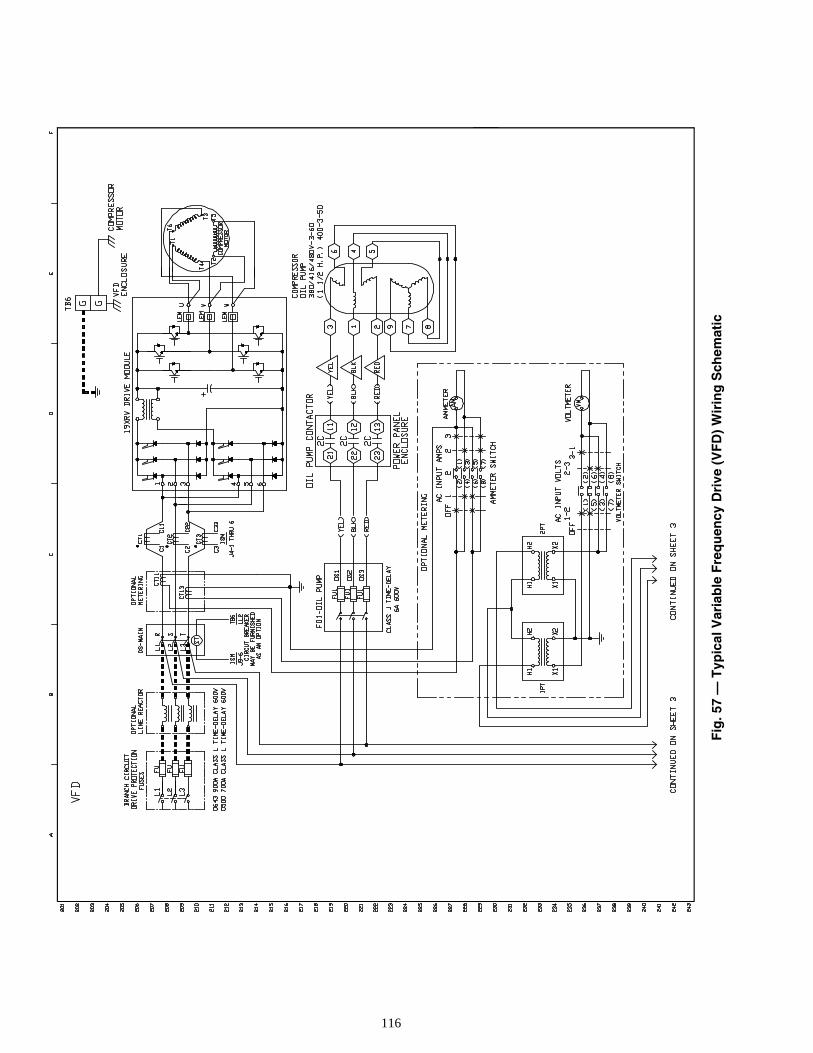
116
Fig
. 57
— T
ypic
al V
aria
ble
Fre
qu
ency
Dri
ve (
VF
D)
Wir
ing
Sch
emat
ic
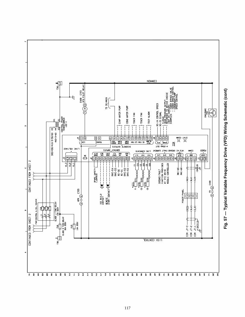
117
Fig
. 57
— T
ypic
al V
aria
ble
Fre
qu
ency
Dri
ve (
VF
D)
Wir
ing
Sch
emat
ic (
con
t)
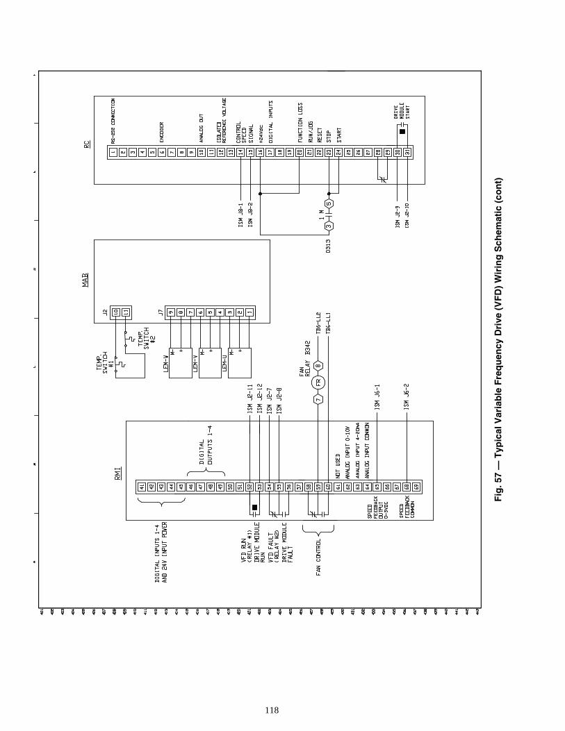
118
Fig
. 57
— T
ypic
al V
aria
ble
Fre
qu
ency
Dri
ve (
VF
D)
Wir
ing
Sch
emat
ic (
con
t)
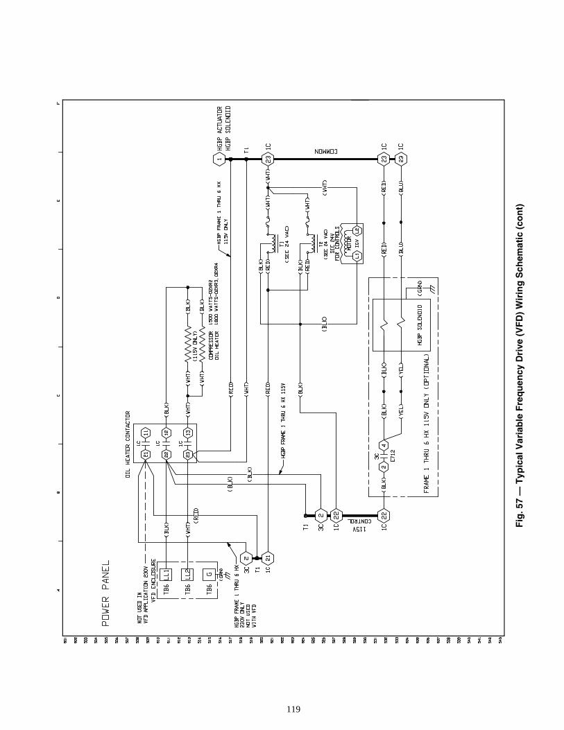
119
Fig
. 57
— T
ypic
al V
aria
ble
Fre
qu
ency
Dri
ve (
VF
D)
Wir
ing
Sch
emat
ic (
con
t)

120
Fig
. 57
— T
ypic
al V
aria
ble
Fre
qu
ency
Dri
ve (
VF
D)
Wir
ing
Sch
emat
ic (
con
t)
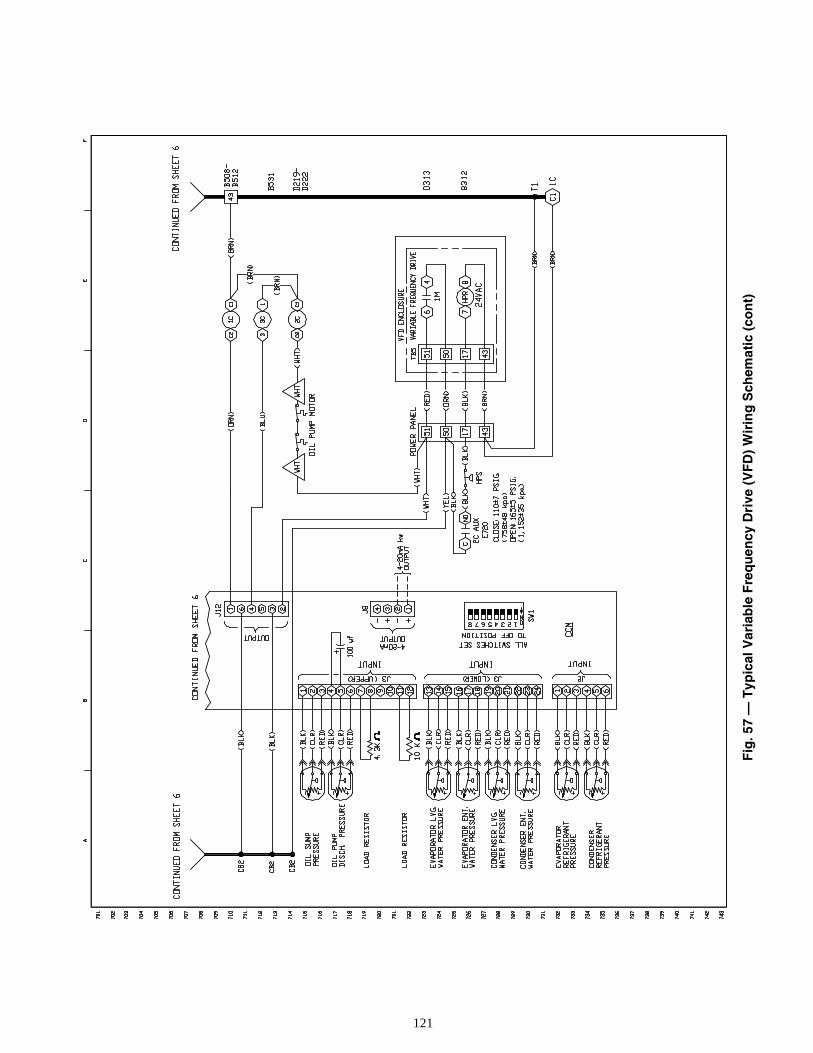
121
Fig
. 57
— T
ypic
al V
aria
ble
Fre
qu
ency
Dri
ve (
VF
D)
Wir
ing
Sch
emat
ic (
con
t)
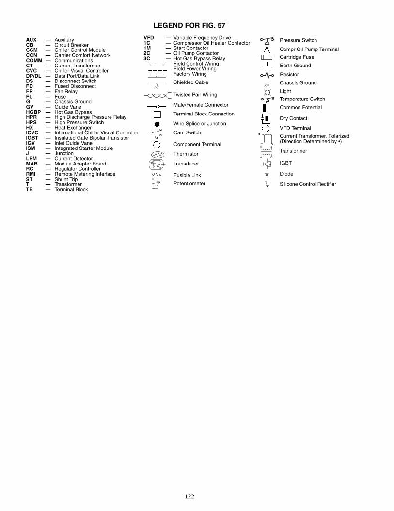
122
LEGEND FOR FIG. 57
AUX — AuxiliaryCB — Circuit BreakerCCM — Chiller Control ModuleCCN — Carrier Comfort NetworkCOMM — CommunicationsCT — Current TransformerCVC — Chiller Visual ControllerDP/DL — Data Port/Data LinkDS — Disconnect SwitchFD — Fused DisconnectFR — Fan RelayFU — FuseG — Chassis GroundGV — Guide VaneHGBP — Hot Gas BypassHPR — High Discharge Pressure RelayHPS — High Pressure SwitchHX — Heat ExchangerICVC — International Chiller Visual ControllerIGBT — Insulated Gate Bipolar TransistorIGV — Inlet Guide VaneISM — Integrated Starter ModuleJ — JunctionLEM — Current DetectorMAB — Module Adapter BoardRC — Regulator ControllerRMI — Remote Metering InterfaceST — Shunt TripT — TransformerTB — Terminal Block
VFD — Variable Frequency Drive1C — Compressor Oil Heater Contactor1M — Start Contactor2C — Oil Pump Contactor3C — Hot Gas Bypass Relay
Field Control WiringField Power WiringFactory Wiring
Shielded Cable
Twisted Pair Wiring
Male/Female Connector
Terminal Block Connection
Wire Splice or Junction
Cam Switch
Component Terminal
Thermistor
Transducer
Fusible Link
Potentiometer
-
+
Pressure Switch
Compr Oil Pump Terminal
Cartridge Fuse
Earth Ground
Resistor
Chassis Ground
Light
Temperature Switch
Common Potential
Dry Contact
VFD Terminal
Current Transformer, Polarized (Direction Determined by •)
Transformer
IGBT
Diode
Silicone Control Rectifier
123
INDEX
Abbreviations and Explanations, 4Adding Refrigerant, 71Adjusting the Refrigerant Charge, 71After Extended Shutdown, 67After Limited Shutdown, 66Alarm (Trip) Output Contacts, 37Attach to Network Device Control, 44Automatic Soft Stop Amps Threshold, 47Auto. Restart After Power Failure, 38Before Initial Start-Up, 48Capacity Override, 36Carrier Comfort Network Interface, 54Changing Oil Filter, 73Charge Refrigerant Into Chiller, 63Chilled Water Recycle Mode, 47Chiller Control Module (CCM), 88Chiller Dehydration, 53Chiller Familiarization, 5Chiller Information Nameplate, 5Chiller Operating Condition (Check), 65Chiller Tightness (Check), 48Chillers with Isolation Valves, 70Chillers with Storage Tanks, 69Cold Weather Operation, 67Compressor Bearing and Gear Maintenance, 74Condenser, 5Condenser Freeze Prevention, 38Condenser Pump Control, 37Control Algorithms Checkout Procedure, 77Control Panel, 5Control Modules, 87Control Test, 77Controls, 10CVC/ICVC Operation and Menus, 15Cooler, 5Default Screen Freeze, 35Definitions (Controls), 10Demand Limit Control Option, 39Design Set Points, (Input), 55Details (Lubrication Cycle), 8Display Messages (Check), 76Dry Run to Test Start-Up Sequence, 65Equipment Required, 48Evaporator Freeze Protection, 38Extended Shutdown (Preparation for), 66Factory-Mounted Starter or Variable Frequency Drive, 7General (Controls), 11General Maintenance, 71Guide Vane Linkage (Check), 72Heat Exchanger Tubes and Flow Devices (Inspect), 74High Altitude Locations, 63High Discharge Temperature Control, 36Ice Build Control, 43Initial Start-Up, 64Initial Start-Up Checklist for 19XR,XRV Hermetic
Centrifugal Liquid Chiller, CL-1Inspect the Control Panel, 73Instruct the Customer Operator, 65Integrated Starter Module (ISM), 88Introduction, 4Job Data Required, 48Kilowatt Output, 37Lead/Lag Control, 40Leak Rate, 71Leak Test Chiller, 50Local Occupied Schedule (Input), 55Local Start-Up, 46Lubrication Cycle, 8Lubrication System (Check), 72Manual Guide Vane Operation, 67
Motor and Lubricating Oil Cooling Cycle, 7Motor-Compressor, 5Motor Rotation (Check), 65Notes on Module Operation, 87Oil Changes, 73Oil Charge, 55Oil Cooler, 36Oil Pressure and Compressor Stop (Check), 65Oil Reclaim Filter, 73Oil Reclaim System, 8Oil Specification, 73Oil Sump Temperature Control, 36Open Oil Circuit Valves, 48Operating Instructions, 66Operating the Optional Pumpout Unit, 67Operator Duties, 66Optional Pumpout Compressor Water Piping (Check), 53Optional Pumpout System Controls and
Compressor (Check), 63Optional Pumpout System Maintenance, 75Ordering Replacement Chiller Parts, 75Overview (Troubleshooting Guide), 76Perform a Control Test, 62Physical Data, 90PIC II System Components, 11PIC II System Functions, 33Power Up the Controls and Check the Oil Heater, 55Preparation (Initial Start-Up), 64Preparation (Pumpout and Refrigerant Transfer
Procedures), 67Prepare the Chiller for Start-Up, 66Pressure Transducers (Check), 75, 76Prevent Accidental Start-Up, 65Pumpout and Refrigerant Transfer Procedures, 67Ramp Loading, 36Refrigerant Filter, 73Refrigerant Float System (Inspect), 74Refrigerant Leak Detector, 37Refrigerant Leak Testing, 71Refrigerant Properties, 71Refrigerant (Removing), 71Refrigerant Tracer, 48Refrigeration Cycle, 7Refrigeration Log, 67Relief Valves (Check), 53Relief Valves and Piping (Inspect), 74Remote Reset of Alarms, 37Remote Start/Stop Controls, 36Repair the Leak, Retest, and
Apply Standing Vacuum Test, 72Replacing Defective Processor Modules, 88Running System (Check), 66Safety and Operating Controls (Check Monthly), 73Safety Considerations, 1Safety Controls, 34Safety Shutdown, 47Scheduled Maintenance, 73Service Configurations (Input), 55Service Ontime, 73Service Operation, 45Shipping Packaging (Remove), 48Shunt Trip (Option), 35Shutdown Sequence, 47Software Configuration, 55Solid-State Starters, 88Spare Safety Inputs, 36Standing Vacuum Test, 50Starter (Check), 54Starting Equipment, 9Starting Equipment (Inspect), 75
Manufacturer reserves the right to discontinue, or change at any time, specifications or designs without notice and without incurring obligations.PC 211 Catalog No. 531-982 Printed in U.S.A. Form 19XR-5SS Pg 124 6-01 Replaces: 19XR-4SSBook 2
Tab 5a
Copyright 2001 Carrier Corporation
INDEX (cont)
Start-Up/Shutdown/Recycle Sequence, 46Start the Chiller, 66Stop the Chiller, 66Storage Vessel, 7Summary (Lubrication Cycle), 8Surge Prevention Algorithm (Fixed Speed Chiller), 39Surge Prevention Algorithm with VFD, 40Surge Protection (Fixed Speed Chillers), 40Surge Protection VFD Units, 40System Components, 5Temperature Sensors (Check), 76Test After Service, Repair, or Major Leak, 71Tighten All Gasketed Joints and Guide Vane Packing, 48Tower Fan Relay Low and High, 38Trim Refrigerant Charge, 72
Troubleshooting Guide, 76Unit-Mounted Solid-State Starter, 9Unit-Mounted VFD, 10Unit-Mounted Wye-Delta Starter, 10Using the Optional Storage Tank and Pumpout
System, 48VFD Cooling Cycle, 8Water/Brine Reset, 38Water Leaks, 74Water Piping (Inspect), 53Water Treatment, 75Weekly Maintenance, 72Wiring (Inspect), 53
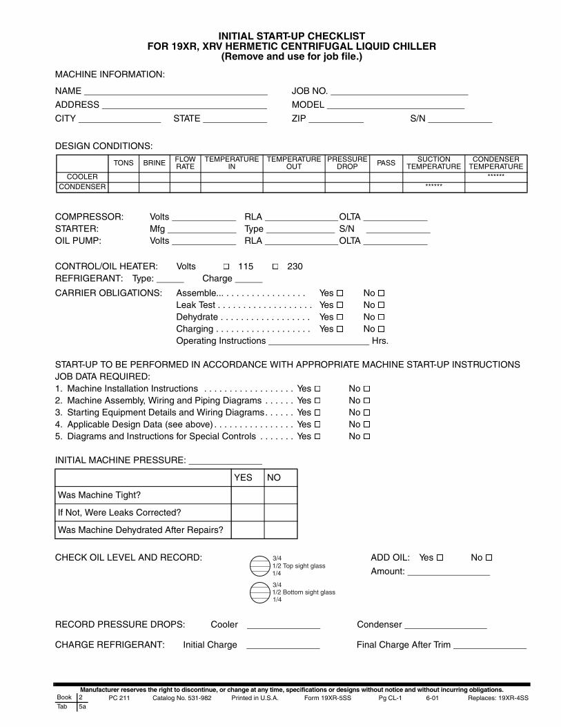
Manufacturer reserves the right to discontinue, or change at any time, specifications or designs without notice and without incurring obligations.PC 211 Catalog No. 531-982 Printed in U.S.A. Form 19XR-5SS Pg CL-1 6-01 Replaces: 19XR-4SSBook 2
Tab 5a
INITIAL START-UP CHECKLISTFOR 19XR, XRV HERMETIC CENTRIFUGAL LIQUID CHILLER
(Remove and use for job file.)
MACHINE INFORMATION:
DESIGN CONDITIONS:
CONTROL/OIL HEATER: Volts � 115 � 230REFRIGERANT: Type: Charge
START-UP TO BE PERFORMED IN ACCORDANCE WITH APPROPRIATE MACHINE START-UP INSTRUCTIONSJOB DATA REQUIRED:1. Machine Installation Instructions . . . . . . . . . . . . . . . . . . Yes � No �2. Machine Assembly, Wiring and Piping Diagrams . . . . . . Yes � No �3. Starting Equipment Details and Wiring Diagrams. . . . . . Yes � No �4. Applicable Design Data (see above) . . . . . . . . . . . . . . . . Yes � No �5. Diagrams and Instructions for Special Controls . . . . . . . Yes � No �
INITIAL MACHINE PRESSURE:
RECORD PRESSURE DROPS: Cooler Condenser
CHARGE REFRIGERANT: Initial Charge Final Charge After Trim
NAME JOB NO.
ADDRESS MODEL
CITY STATE ZIP S/N
TONS BRINE FLOWRATE
TEMPERATUREIN
TEMPERATUREOUT
PRESSUREDROP PASS SUCTION
TEMPERATURECONDENSER
TEMPERATURECOOLER ******
CONDENSER ******
COMPRESSOR: Volts RLA OLTA STARTER: Mfg Type S/N OIL PUMP: Volts RLA OLTA
CARRIER OBLIGATIONS: Assemble... . . . . . . . . . . . . . . . . Yes � No �Leak Test . . . . . . . . . . . . . . . . . . . Yes � No �Dehydrate . . . . . . . . . . . . . . . . . . Yes � No �Charging . . . . . . . . . . . . . . . . . . . Yes � No �Operating Instructions Hrs.
YES NO
Was Machine Tight?
If Not, Were Leaks Corrected?
Was Machine Dehydrated After Repairs?
CHECK OIL LEVEL AND RECORD: ADD OIL: Yes � No �
Amount: 1/2 Top sight glass
1/2 Bottom sight glass
3/4
1/4
3/4
1/4
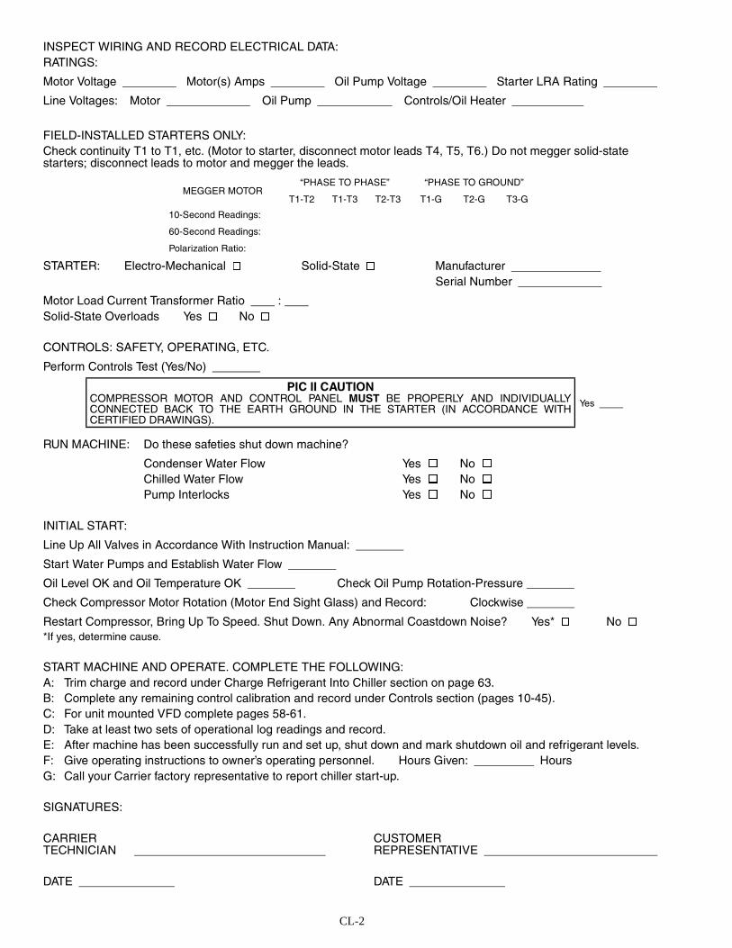
CL-2
INSPECT WIRING AND RECORD ELECTRICAL DATA:RATINGS:
Motor Voltage Motor(s) Amps Oil Pump Voltage Starter LRA Rating
Line Voltages: Motor Oil Pump Controls/Oil Heater
FIELD-INSTALLED STARTERS ONLY:Check continuity T1 to T1, etc. (Motor to starter, disconnect motor leads T4, T5, T6.) Do not megger solid-statestarters; disconnect leads to motor and megger the leads.
STARTER: Electro-Mechanical � Solid-State � ManufacturerSerial Number
Motor Load Current Transformer Ratio : Solid-State Overloads Yes � No �
CONTROLS: SAFETY, OPERATING, ETC.
Perform Controls Test (Yes/No)
INITIAL START:
Line Up All Valves in Accordance With Instruction Manual:
Start Water Pumps and Establish Water Flow
Oil Level OK and Oil Temperature OK Check Oil Pump Rotation-Pressure
Check Compressor Motor Rotation (Motor End Sight Glass) and Record: Clockwise
Restart Compressor, Bring Up To Speed. Shut Down. Any Abnormal Coastdown Noise? Yes* � No �*If yes, determine cause.
START MACHINE AND OPERATE. COMPLETE THE FOLLOWING:A: Trim charge and record under Charge Refrigerant Into Chiller section on page 63.B: Complete any remaining control calibration and record under Controls section (pages 10-45).C: For unit mounted VFD complete pages 58-61.D: Take at least two sets of operational log readings and record.E: After machine has been successfully run and set up, shut down and mark shutdown oil and refrigerant levels.F: Give operating instructions to owner’s operating personnel. Hours Given: HoursG: Call your Carrier factory representative to report chiller start-up.
SIGNATURES:
CARRIERTECHNICIAN
DATE
CUSTOMERREPRESENTATIVE
DATE
MEGGER MOTOR“PHASE TO PHASE” “PHASE TO GROUND”
T1-T2 T1-T3 T2-T3 T1-G T2-G T3-G
10-Second Readings:
60-Second Readings:
Polarization Ratio:
PIC II CAUTIONCOMPRESSOR MOTOR AND CONTROL PANEL MUST BE PROPERLY AND INDIVIDUALLYCONNECTED BACK TO THE EARTH GROUND IN THE STARTER (IN ACCORDANCE WITHCERTIFIED DRAWINGS).
Yes
RUN MACHINE: Do these safeties shut down machine?
Condenser Water Flow Yes � No �Chilled Water Flow Yes � No �Pump Interlocks Yes � No �
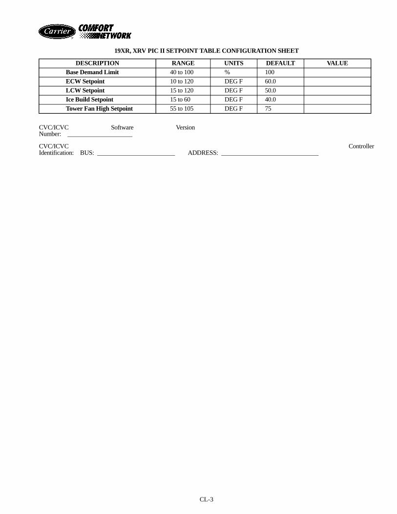
CL-3
19XR, XRV PIC II SETPOINT TABLE CONFIGURATION SHEET
CVC/ICVC Software VersionNumber:
CVC/ICVC ControllerIdentification: BUS: ADDRESS:
DESCRIPTION RANGE UNITS DEFAULT VALUEBase Demand Limit 40 to 100 % 100
ECW Setpoint 10 to 120 DEG F 60.0
LCW Setpoint 15 to 120 DEG F 50.0
Ice Build Setpoint 15 to 60 DEG F 40.0
Tower Fan High Setpoint 55 to 105 DEG F 75
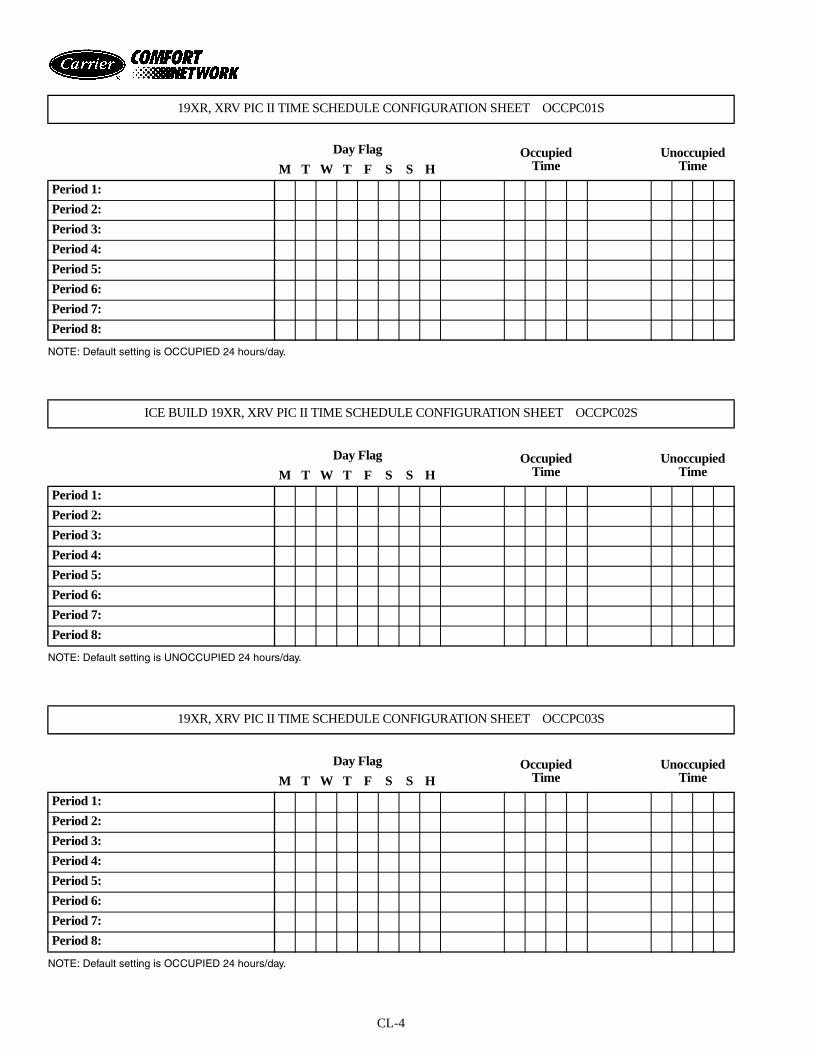
CL-4
NOTE: Default setting is OCCUPIED 24 hours/day.
NOTE: Default setting is UNOCCUPIED 24 hours/day.
NOTE: Default setting is OCCUPIED 24 hours/day.
19XR, XRV PIC II TIME SCHEDULE CONFIGURATION SHEET OCCPC01S
Day Flag OccupiedTime
UnoccupiedTimeM T W T F S S H
Period 1:
Period 2:
Period 3:
Period 4:
Period 5:
Period 6:
Period 7:
Period 8:
ICE BUILD 19XR, XRV PIC II TIME SCHEDULE CONFIGURATION SHEET OCCPC02S
Day Flag OccupiedTime
UnoccupiedTimeM T W T F S S H
Period 1:
Period 2:
Period 3:
Period 4:
Period 5:
Period 6:
Period 7:
Period 8:
19XR, XRV PIC II TIME SCHEDULE CONFIGURATION SHEET OCCPC03S
Day Flag OccupiedTime
UnoccupiedTimeM T W T F S S H
Period 1:
Period 2:
Period 3:
Period 4:
Period 5:
Period 6:
Period 7:
Period 8:
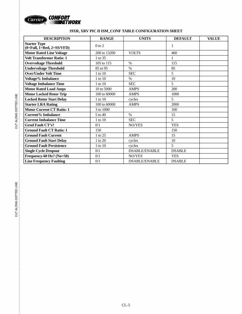
CL-5
CU
T A
LON
G D
OT
TE
D L
INE
CU
T A
LON
G D
OT
TE
D L
INE
- -
- -
- -
- -
- -
- -
- -
- -
- -
- -
- -
- -
- -
- -
- -
- -
- -
- -
- -
- -
- -
- -
- -
- -
- -
- -
- -
- -
- -
- -
- -
- -
- -
- -
- -
- -
- -
- -
- -
- -
- -
- -
- -
- -
- -
- -
- -
- -
- -
- -
- -
- -
- -
- -
- -
- -
- -
- -
- -
- -
- -
- -
- -
- -
- -
- -
- -
- -
- -
- -
- -
- -
- -
- -
- -
- -
- -
- -
- -
- -
- -
- -
- -
- -
- -
- -
- -
-- -
- -
- -
- -
- -
- -
- -
- -
- -
-
19XR, XRV PIC II ISM_CONF TABLE CONFIGURATION SHEET
DESCRIPTION RANGE UNITS DEFAULT VALUEStarter Type(0=Full, 1=Red, 2=SS/VFD) 0 to 2 1
Motor Rated Line Voltage 200 to 13200 VOLTS 460Volt Transformer Ratio: 1 1 to 35 1Overvoltage Threshold 105 to 115 % 115Undervoltage Threshold 85 to 95 % 85Over/Under Volt Time 1 to 10 SEC 5Voltage% Imbalance 1 to 10 % 10Voltage Imbalance Time 1 to 10 SEC 5Motor Rated Load Amps 10 to 5000 AMPS 200Motor Locked Rotor Trip 100 to 60000 AMPS 1000Locked Rotor Start Delay 1 to 10 cycles 5Starter LRA Rating 100 to 60000 AMPS 2000Motor Current CT Ratio: 1 3 to 1000 100Current% Imbalance 5 to 40 % 15Current Imbalance Time 1 to 10 SEC 5Grnd Fault CT’s? 0/1 NO/YES YESGround Fault CT Ratio: 1 150 150Ground Fault Current 1 to 25 AMPS 15Ground Fault Start Delay 1 to 20 cycles 10Ground Fault Persistence 1 to 10 cycles 5Single Cycle Dropout 0/1 DSABLE/ENABLE DSABLEFrequency-60 Hz? (No=50) 0/1 NO/YES YESLine Frequency Faulting 0/1 DSABLE/ENABLE DSABLE
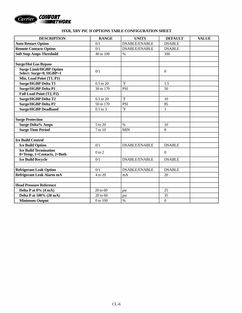
CL-6
19XR, XRV PIC II OPTIONS TABLE CONFIGURATION SHEET
DESCRIPTION RANGE UNITS DEFAULT VALUEAuto Restart Option 0/1 DSABLE/ENABLE DSABLERemote Contacts Option 0/1 DSABLE/ENABLE DSABLESoft Stop Amps Threshold 40 to 100 % 100
Surge/Hot Gas BypassSurge Limit/HGBP OptionSelect: Surge=0, HGBP=1 0/1 0
Min. Load Point (T1, P1)Surge/HGBP Delta T1 0.5 to 20 ˆF 1.5Surge/HGBP Delta P1 30 to 170 PSI 50Full Load Point (T2, P2)Surge/HGBP Delta T2 0.5 to 20 ˆF 10Surge/HGBP Delta P2 50 to 170 PSI 85Surge/HGBP Deadband 0.5 to 3 ˆF 1
Surge ProtectionSurge Delta% Amps 5 to 20 % 10Surge Time Period 7 to 10 MIN 8
Ice Build ControlIce Build Option 0/1 DSABLE/ENABLE DSABLEIce Build Termination0=Temp, 1=Contacts, 2=Both 0 to 2 0
Ice Build Recycle 0/1 DSABLE/ENABLE DSABLE
Refrigerant Leak Option 0/1 DSABLE/ENABLE DSABLERefrigerant Leak Alarm mA 4 to 20 mA 20
Head Pressure ReferenceDelta P at 0% (4 mA) 20 to 60 psi 25Delta P at 100% (20 mA) 20 to 60 psi 35Minimum Output 0 to 100 % 0
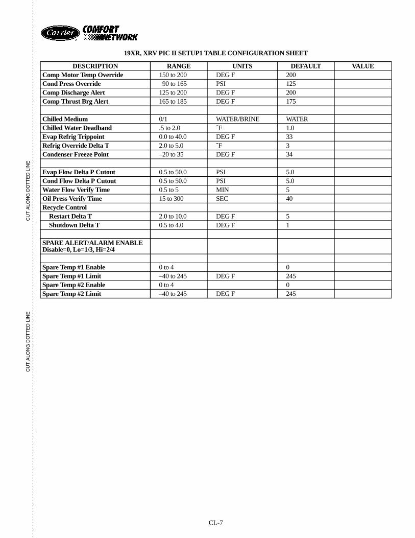
CL-7
CU
T A
LON
G D
OT
TE
D L
INE
CU
T A
LON
G D
OT
TE
D L
INE
- -
- -
- -
- -
- -
- -
- -
- -
- -
- -
- -
- -
- -
- -
- -
- -
- -
- -
- -
- -
- -
- -
- -
- -
- -
- -
- -
- -
- -
- -
- -
- -
- -
- -
- -
- -
- -
- -
- -
- -
- -
- -
- -
- -
- -
- -
- -
- -
- -
- -
- -
- -
- -
- -
- -
- -
- -
- -
- -
- -
- -
- -
- -
- -
- -
- -
- -
- -
- -
- -
- -
- -
- -
- -
- -
- -
- -
- -
- -
- -
- -
- -
- -
- -
- -
- -
- -
-- -
- -
- -
- -
- -
- -
- -
- -
- -
-
19XR, XRV PIC II SETUP1 TABLE CONFIGURATION SHEET
DESCRIPTION RANGE UNITS DEFAULT VALUEComp Motor Temp Override 150 to 200 DEG F 200Cond Press Override 90 to 165 PSI 125Comp Discharge Alert 125 to 200 DEG F 200Comp Thrust Brg Alert 165 to 185 DEG F 175
Chilled Medium 0/1 WATER/BRINE WATERChilled Water Deadband .5 to 2.0 ˆF 1.0Evap Refrig Trippoint 0.0 to 40.0 DEG F 33Refrig Override Delta T 2.0 to 5.0 ˆF 3Condenser Freeze Point –20 to 35 DEG F 34
Evap Flow Delta P Cutout 0.5 to 50.0 PSI 5.0Cond Flow Delta P Cutout 0.5 to 50.0 PSI 5.0Water Flow Verify Time 0.5 to 5 MIN 5Oil Press Verify Time 15 to 300 SEC 40Recycle Control
Restart Delta T 2.0 to 10.0 DEG F 5Shutdown Delta T 0.5 to 4.0 DEG F 1
SPARE ALERT/ALARM ENABLEDisable=0, Lo=1/3, Hi=2/4
Spare Temp #1 Enable 0 to 4 0Spare Temp #1 Limit –40 to 245 DEG F 245Spare Temp #2 Enable 0 to 4 0Spare Temp #2 Limit –40 to 245 DEG F 245
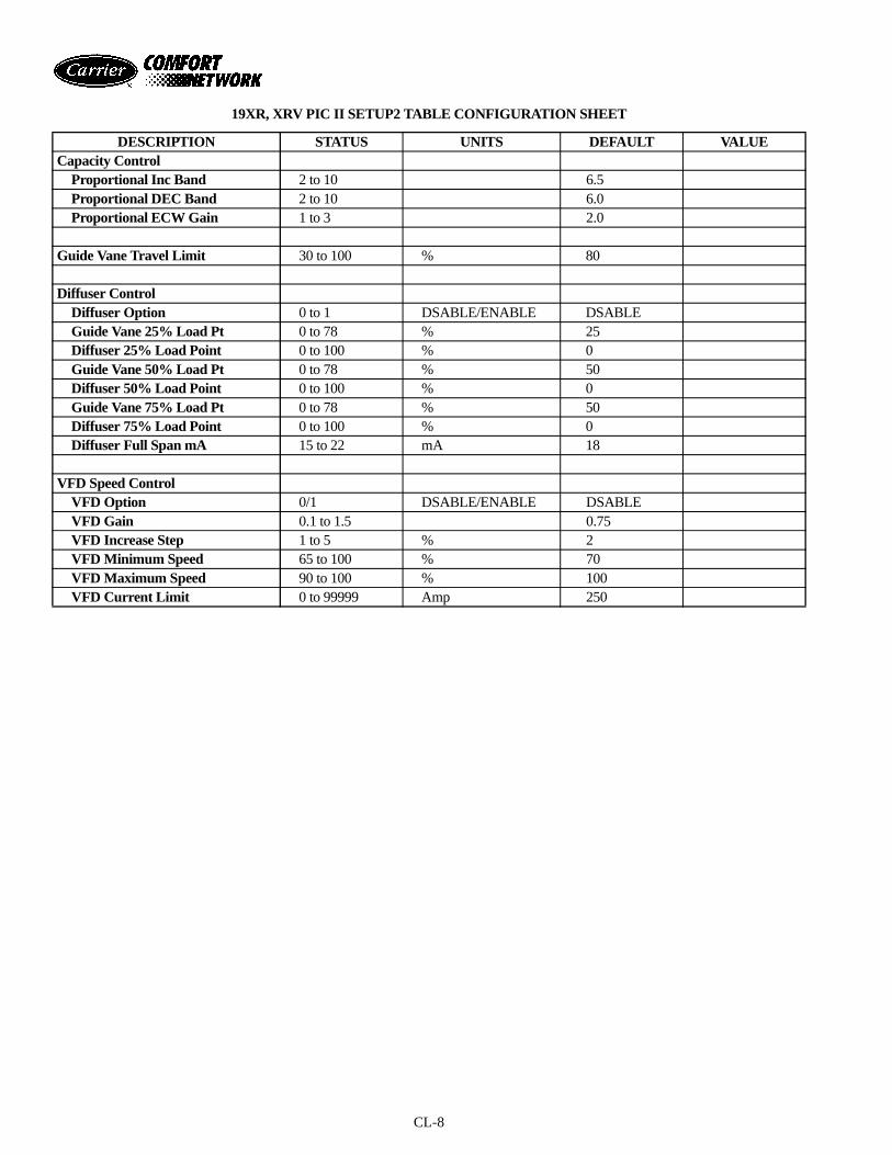
CL-8
19XR, XRV PIC II SETUP2 TABLE CONFIGURATION SHEET
DESCRIPTION STATUS UNITS DEFAULT VALUECapacity Control
Proportional Inc Band 2 to 10 6.5Proportional DEC Band 2 to 10 6.0Proportional ECW Gain 1 to 3 2.0
Guide Vane Travel Limit 30 to 100 % 80
Diffuser ControlDiffuser Option 0 to 1 DSABLE/ENABLE DSABLEGuide Vane 25% Load Pt 0 to 78 % 25Diffuser 25% Load Point 0 to 100 % 0Guide Vane 50% Load Pt 0 to 78 % 50Diffuser 50% Load Point 0 to 100 % 0Guide Vane 75% Load Pt 0 to 78 % 50Diffuser 75% Load Point 0 to 100 % 0Diffuser Full Span mA 15 to 22 mA 18
VFD Speed ControlVFD Option 0/1 DSABLE/ENABLE DSABLEVFD Gain 0.1 to 1.5 0.75VFD Increase Step 1 to 5 % 2VFD Minimum Speed 65 to 100 % 70VFD Maximum Speed 90 to 100 % 100VFD Current Limit 0 to 99999 Amp 250
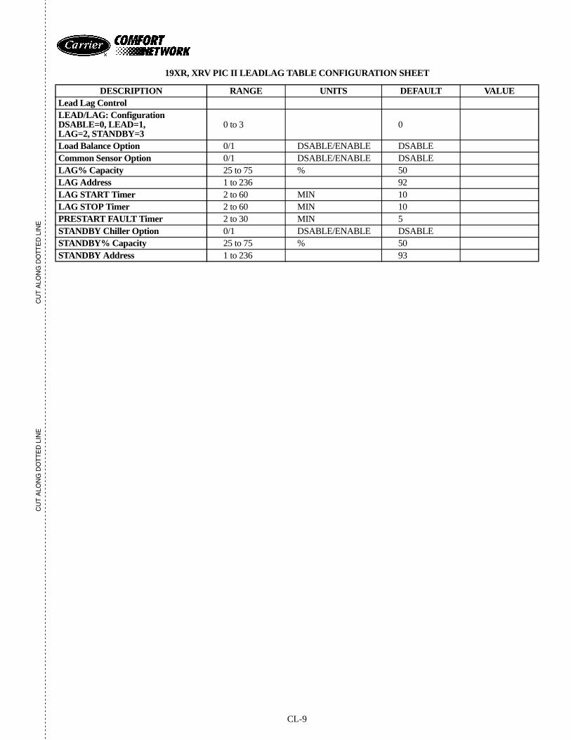
CL-9
CU
T A
LON
G D
OT
TE
D L
INE
CU
T A
LON
G D
OT
TE
D L
INE
- -
- -
- -
- -
- -
- -
- -
- -
- -
- -
- -
- -
- -
- -
- -
- -
- -
- -
- -
- -
- -
- -
- -
- -
- -
- -
- -
- -
- -
- -
- -
- -
- -
- -
- -
- -
- -
- -
- -
- -
- -
- -
- -
- -
- -
- -
- -
- -
- -
- -
- -
- -
- -
- -
- -
- -
- -
- -
- -
- -
- -
- -
- -
- -
- -
- -
- -
- -
- -
- -
- -
- -
- -
- -
- -
- -
- -
- -
- -
- -
- -
- -
- -
- -
- -
- -
- -
-- -
- -
- -
- -
- -
- -
- -
- -
- -
-
19XR, XRV PIC II LEADLAG TABLE CONFIGURATION SHEET
DESCRIPTION RANGE UNITS DEFAULT VALUELead Lag ControlLEAD/LAG: ConfigurationDSABLE=0, LEAD=1,LAG=2, STANDBY=3
0 to 3 0
Load Balance Option 0/1 DSABLE/ENABLE DSABLECommon Sensor Option 0/1 DSABLE/ENABLE DSABLELAG% Capacity 25 to 75 % 50LAG Address 1 to 236 92LAG START Timer 2 to 60 MIN 10LAG STOP Timer 2 to 60 MIN 10PRESTART FAULT Timer 2 to 30 MIN 5STANDBY Chiller Option 0/1 DSABLE/ENABLE DSABLESTANDBY% Capacity 25 to 75 % 50STANDBY Address 1 to 236 93
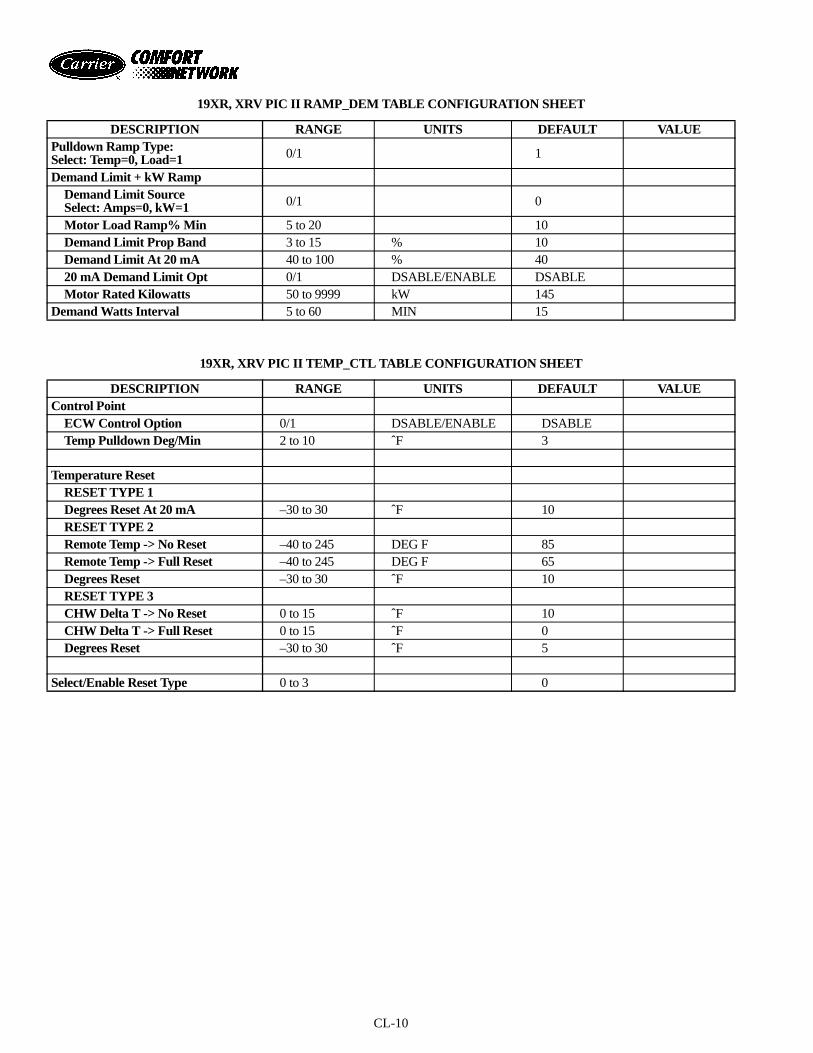
CL-10
19XR, XRV PIC II RAMP_DEM TABLE CONFIGURATION SHEET
19XR, XRV PIC II TEMP_CTL TABLE CONFIGURATION SHEET
DESCRIPTION RANGE UNITS DEFAULT VALUEPulldown Ramp Type:Select: Temp=0, Load=1 0/1 1
Demand Limit + kW RampDemand Limit SourceSelect: Amps=0, kW=1 0/1 0
Motor Load Ramp% Min 5 to 20 10Demand Limit Prop Band 3 to 15 % 10Demand Limit At 20 mA 40 to 100 % 4020 mA Demand Limit Opt 0/1 DSABLE/ENABLE DSABLEMotor Rated Kilowatts 50 to 9999 kW 145
Demand Watts Interval 5 to 60 MIN 15
DESCRIPTION RANGE UNITS DEFAULT VALUEControl Point
ECW Control Option 0/1 DSABLE/ENABLE DSABLETemp Pulldown Deg/Min 2 to 10 ˆF 3
Temperature ResetRESET TYPE 1Degrees Reset At 20 mA –30 to 30 ˆF 10RESET TYPE 2Remote Temp -> No Reset –40 to 245 DEG F 85Remote Temp -> Full Reset –40 to 245 DEG F 65Degrees Reset –30 to 30 ˆF 10RESET TYPE 3CHW Delta T -> No Reset 0 to 15 ˆF 10CHW Delta T -> Full Reset 0 to 15 ˆF 0Degrees Reset –30 to 30 ˆF 5
Select/Enable Reset Type 0 to 3 0
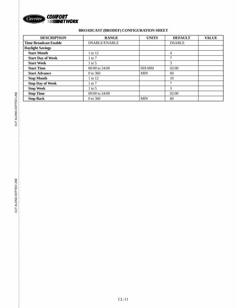
CL-11
CU
T A
LON
G D
OT
TE
D L
INE
CU
T A
LON
G D
OT
TE
D L
INE
- -
- -
- -
- -
- -
- -
- -
- -
- -
- -
- -
- -
- -
- -
- -
- -
- -
- -
- -
- -
- -
- -
- -
- -
- -
- -
- -
- -
- -
- -
- -
- -
- -
- -
- -
- -
- -
- -
- -
- -
- -
- -
- -
- -
- -
- -
- -
- -
- -
- -
- -
- -
- -
- -
- -
- -
- -
- -
- -
- -
- -
- -
- -
- -
- -
- -
- -
- -
- -
- -
- -
- -
- -
- -
- -
- -
- -
- -
- -
- -
- -
- -
- -
- -
- -
- -
- -
-- -
- -
- -
- -
- -
- -
- -
- -
- -
-
BROADCAST (BRODEF) CONFIGURATION SHEET
DESCRIPTION RANGE UNITS DEFAULT VALUETime Broadcast Enable DSABLE/ENABLE DSABLEDaylight Savings
Start Month 1 to 12 4Start Day of Week 1 to 7 7Start Week 1 to 5 3Start Time 00:00 to 24:00 HH:MM 02:00Start Advance 0 to 360 MIN 60Stop Month 1 to 12 10Stop Day of Week 1 to 7 7Stop Week 1 to 5 3Stop Time 00:00 to 24:00 02:00Stop Back 0 to 360 MIN 60
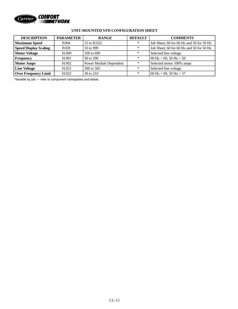
CL-12
UNIT-MOUNTED VFD CONFIGURATION SHEET
*Variable by job — refer to component nameplates and labels.
DESCRIPTION PARAMETER RANGE DEFAULT COMMENTSMaximum Speed P.004 15 to H.022 * Job Sheet; 60 for 60 Hz and 50 for 50 HzSpeed Display Scaling P.028 10 to 999 * Job Sheet; 60 for 60 Hz and 50 for 50 HzMotor Voltage H.000 100 to 690 * Selected line voltageFrequency H.001 30 to 200 * 60 Hz = 60, 50 Hz = 50Motor Amps H.002 Power Module Dependent * Selected motor 100% ampsLine Voltage H.021 300 to 565 * Selected line voltageOver Frequency Limit H.022 30 to 210 * 60 Hz = 69, 50 Hz = 57
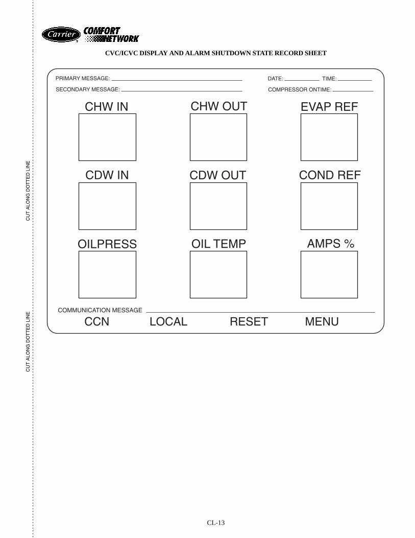
CL-13
CU
T A
LON
G D
OT
TE
D L
INE
CU
T A
LON
G D
OT
TE
D L
INE
- -
- -
- -
- -
- -
- -
- -
- -
- -
- -
- -
- -
- -
- -
- -
- -
- -
- -
- -
- -
- -
- -
- -
- -
- -
- -
- -
- -
- -
- -
- -
- -
- -
- -
- -
- -
- -
- -
- -
- -
- -
- -
- -
- -
- -
- -
- -
- -
- -
- -
- -
- -
- -
- -
- -
- -
- -
- -
- -
- -
- -
- -
- -
- -
- -
- -
- -
- -
- -
- -
- -
- -
- -
- -
- -
- -
- -
- -
- -
- -
- -
- -
- -
- -
- -
- -
- -
-- -
- -
- -
- -
- -
- -
- -
- -
- -
-
CVC/ICVC DISPLAY AND ALARM SHUTDOWN STATE RECORD SHEET
PRIMARY MESSAGE:
SECONDARY MESSAGE:
DATE: TIME:
COMPRESSOR ONTIME:
CHW IN
OILPRESS
CHW OUT
OIL TEMP
CDW IN CDW OUT
EVAP REF
COND REF
AMPS %
COMMUNICATION MESSAGE
CCN LOCAL RESET MENU
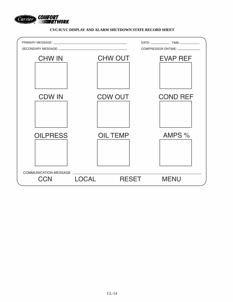
CL-14
CVC/ICVC DISPLAY AND ALARM SHUTDOWN STATE RECORD SHEET
PRIMARY MESSAGE:
SECONDARY MESSAGE:
DATE: TIME:
COMPRESSOR ONTIME:
CHW IN
OILPRESS
CHW OUT
OIL TEMP
CDW IN CDW OUT
EVAP REF
COND REF
AMPS %
COMMUNICATION MESSAGE
CCN LOCAL RESET MENU

Manufacturer reserves the right to discontinue, or change at any time, specifications or designs without notice and without incurring obligations.PC 211 Catalog No. 531-982 Printed in U.S.A. Form 19XR-5SS Pg CL-16 6-01 Replaces: 19XR-4SSBook 2
Tab 5a
Copyright 2001 Carrier Corporation
- -
- -
- -
- -
- -
- -
- -
- -
- -
- -
- -
- -
- -
- -
- -
- -
- -
- -
- -
- -
- -
- -
- -
- -
- -
- -
- -
- -
- -
- -
- -
- -
- -
- -
- -
- -
- -
- -
- -
- -
- -
- -
- -
- -
- -
- -
- -
- -
- -
- -
- -
- -
- -
- -
- -
- -
- -
- -
- -
- -
- -
- -
- -
- -
- -
- -
- -
- -
- -
- -
- -
- -
- -
- -
- -
- -
- -
- -
- -
- -
- -
- -
- -
- -
- -
- -
- --
- -
- -
- -
- -
- -
- -
- -
- -
- -
-
CU
T A
LON
G D
OT
TE
D L
INE
CU
T A
LON
G D
OT
TE
D L
INE