STARAN Parallel processor system hardware By KENNETH E. BATCHER Presented by Manoj k. Yarlagadda...
25
STARAN Parallel STARAN Parallel processor system processor system hardware hardware By By KENNETH E. BATCHER KENNETH E. BATCHER Presented by Manoj k. Yarlagadda Manoj k. Yarlagadda
-
Upload
tobias-lynch -
Category
Documents
-
view
217 -
download
1
Transcript of STARAN Parallel processor system hardware By KENNETH E. BATCHER Presented by Manoj k. Yarlagadda...
STARAN Parallel processor STARAN Parallel processor system hardwaresystem hardware
ByByKENNETH E. BATCHERKENNETH E. BATCHER
Presented by Manoj k. YarlagaddaManoj k. Yarlagadda
Presentation TopicsPresentation Topics
• Parallel Processors
• Why Parallelism?
• Why Parallelism Now?
• EVOLUTION OF STARAN!
• STARAN Configuration Diagram
• Multi-Dimensional Access (MDA)
• STARAN BLOCK DIAGRAM

Parallel ProcessorsParallel Processors
• Interconnection Networks
• SIMD Computers
• MIMD Computers
• Other Architectures– Dataflow and Neural Network

SIMD SIMD MIMDMIMD
There are N data streams, one per processor so different data can be used in each processor.
Each processor operates under the control of an instruction stream issued by its own control unit

Why Parallelism?Why Parallelism?
• Even though the CPU-memory connection is a bottleneck, we are still greatly interested in processor speed up. Parallelism can be used in the following are:– Simulations of complex physical systems (e.g.,
weather forecasting, molecular modeling)– Image processing– Massive data processing (e.g., seismic data)– Large databases

Why Parallelism Now?Why Parallelism Now?• Parallel Processors have been available for
decades, but only due to recent technological changes have they become feasible:– Evolution of ICs to current VLSI (or VVLSI)– Dramatic reduction in power requirements– Decreased cost of production– Increased speed of processors– Increased reliability of processors
• Current SIMD machines have up to 65,336 PEs!
EVOLUTION OF STARANEVOLUTION OF STARAN• High cost of semiconductor memory and logic elements.• The Versions of Associative processor (AP):
1) Built for USAF by Goodyear Aerospace Corporation June 1969 at Akron, Ohio.
2) The same machine updated including large Instruction memory, was loaned by USAF in 1971.
3) The lessons learned in programming and testing the USAF AP model resulted in a new design called STARAN S which was commited to production in 1971.

…Contd
4) Demonstrations in May 1972 at TRANSPO exhibit in Washington D.C. and June, 1972 at Boston.
The initial uses of AP’s would be weighted toward real- time applications involving interface with a wide variety of sensors, Conventional computers, signal processors, interactive displays and mass storage devises. To accommodate all such interfaces the STARAN was divided into

STARAN Configuration DigSTARAN Configuration Dig• Standardized main frame
unit• Custom interface unit:
a) A variety of I/O operation includes
Direct memory access (DMA)
Buffered I/O channels
External function channels
Unique interface called Parallel I/O
MDA MEMORIESMDA MEMORIES
• The Memory for such an associative processor could be a simple random-access memory with data rotated 90-deg, so that it is accessed by bit-slices instead of by words.
• The MDA memory is treated as a square array of bits, 256 words with 256 bits in each word.
• To Accommodate both bit-slice accesses for associative processing and word-slice accesses for STARAN input/output the Data are stored in MDA (Multi dimensional access memory)

..Contd
• It has Read/Write busses for parallel access to a large number of (256) of memory bits.
• Write mask bus for selective writing of bits.
• Memory accesses (Read & Write) are controlled by address & access mode controlled I/P’s
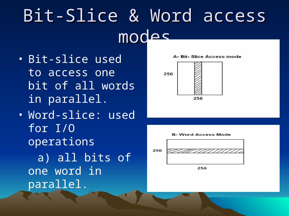
Bit-Slice & Word access modesBit-Slice & Word access modes
• Bit-slice used to access one bit of all words in parallel.
• Word-slice: used for I/O operations
a) all bits of one word in parallel.
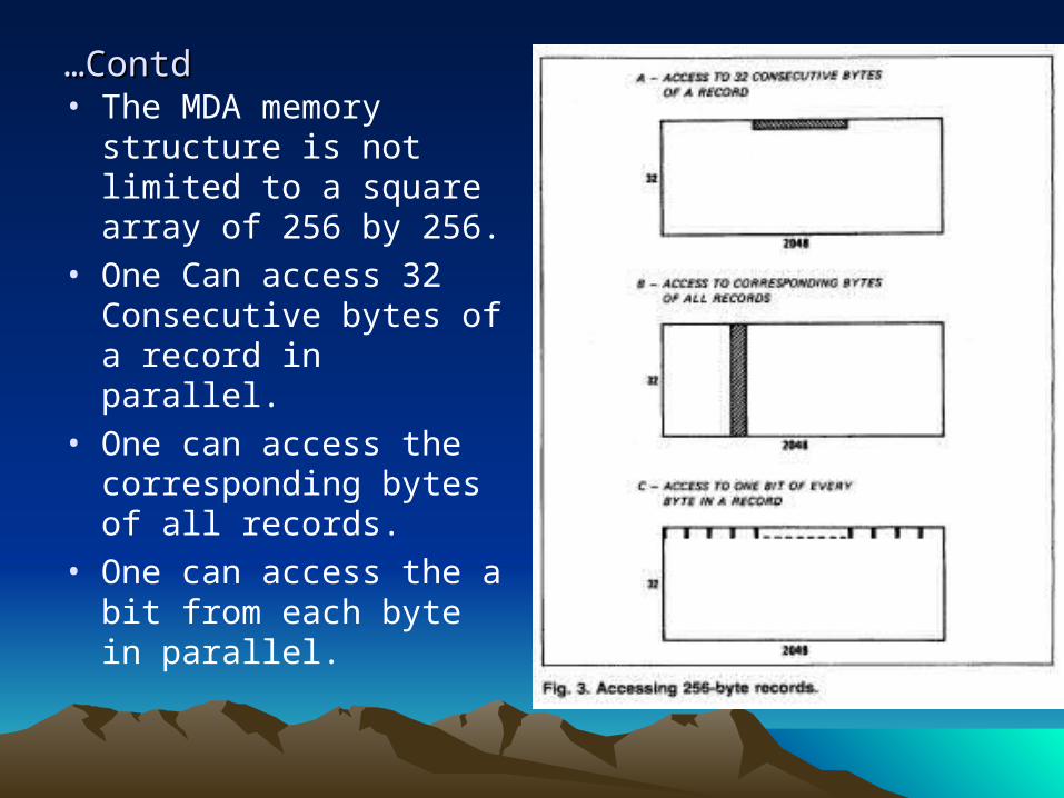
……ContdContd• The MDA memory
structure is not limited to a square array of 256 by 256.
• One Can access 32 Consecutive bytes of a record in parallel.
• One can access the corresponding bytes of all records.
• One can access the a bit from each byte in parallel.

STARAN ARRAY MODULESSTARAN ARRAY MODULES

…Contd
1) Array module components communicate through a network called flip network.
2) Selector Chooses a 256-bit source item from MDA read bus.
3) Flip network Which may shift & permute the bits in various ways.
a) It allows the inter-PE communication. A PE can read the data from another PE directly or indirectly MDA or from registers.
b) It can permute the 256-bit data item as whole or divide it into groups like 2, 4, 8, 16, 32, 64 or 128 bits.
4) Mirroring Reduce the number of passes.
…Contd
5) Three 256-bit Registers (M,X, and Y) through a flip network. Note: X & Y-> logic registers
6) The general logic associated with the X-register can perform any 16 Boolean functions of two variables
If xi is the state of the ith X-Register bit, and fI is the state of the ith flip network output Then,
xi <- Ø (xi, fi ) (i = 0, 1, . . . , 255) Ø Boolean function
Y-Register:
yi <- Ø( yi, fi) (i = 0,1, . . . , 255)

4) If X & Y are operated together, the same Boolean function, F is applied to both registers. xi <- Ø (xi, fi) yi <- Ø(yi, fi)5) The programmer also can choose to operate on X selectively, using Y as a mask:
xi <- Ø(xi, fi) (where yi = 1) xi <- xi (where yi = 0)6) Another choice is to operate on X selectively while operating on Y: xi <- Ø (xi, fi) (where yi = 1) xi <- xi (where yi = 0) yi <- Ø (yi, fi)In this case, the old state of Y (before modification by f ) is used as the mask for the X operation.

Programming exampleProgramming example
• This operation adds the contents of a Field A of all memory words to the contents of a Field B of the words
and stores the sum in a Field S of the words. • At the beginning of each loop execution, the carry (c)
from the previous bits is stored in Y, and X contains
zeroes: xi = 0
yi = ci Note: Start with LSB to MSB

Four steps :Four steps :Step 1: Read Bit-slice a and exclusive-or () it to X selectively
and also to Y:xi <- xi yi .ai yi<- yi ai
The states of X and Y are now:xi = ai.ci
yi = ai ci
Step 2: Read Bit-slice b and exclusive-or it to X selectively and also to Y:
xi <- xi yi.bi
Yi <- yi bi
Registers X and Y now contain the carry and sum bits: xi=ai ci ai.bi bi.ci = c'i yi= ai bi ci = si
…Contd
Step 3: Write the sum bit from Y into Bit-slice s and also complement X selectively:
si <- yixi <- xi yi
The states of X and Y are now:xi= c‘i siyi = si
Step 4: Read the X-register and exclusive-or it into both X and Y:
xi <- xi xiyi <- yi xi
clear X and store the carry bit into Y for next execution of the loop: xi = 0 yi= c‘i

STARAN BLOCK DIAGRAMSTARAN BLOCK DIAGRAM• Assignment switch:
Connects it’s control I/P & Data I/P and outputs to AP.
• AP( Associative processor) : Contains Reg & logic.
It receives instructions from the Control memory & transfer the data to and from Control memory.

Registers in the AP:
1) Instruction Register: To hold the 32-bit instruction being executed.
2) Program status word: To hold the CM address of the next instruction to be executed and the program priority level.
3) Common register: to hold a 32-bit search command
4) Array select Reg: to Select a subset of assigned register
5) Four field pointers: To hold MDA addresses
6) Three Counters: To keep track of number of executions of loops.
7) Data pointer : To allow stepping through a set of operands in CM.
8) Two access Mode Reg: To hold the MDA access modes

Parallel input/output module (PIO):
1) PIO flip network
a) Port 0 to 3 connects to 4 Array modules
b) Port 7 connects to the 32 bit data bus in PIO control through a fan-in & fan-out switch
c) Port 6,5,4 are Spare (High bandwidth peripherals, Radar)
2) PIO Control unit ( Controls the array modules, FLIP)
3) Control memory ( It has 5 Banks of bipolar memory)
4) DEC/PDP-11 ( To handle the peripherals, control the system from console commands.
5) External function ( It controls AP & Sequential & PIO )

STARAN ApplicationsSTARAN Applications
• Fast Fourier Transform (used in Real-time processing of radar and sonar signals)
• Sonar post- processing ( Signal processing & Post processing)
• String search (Searching a string is 100 times faster than conventional computer search.)
• File processing• Air traffic control

Architectures for ApplicationsArchitectures for Applications• Fast Fourier Transform : Speed increases over
sequential computers
STARAN leads itself to efficient manipulation of data in the FFT.
Ex: Air Force supplied radar data to GAC
By using 512-point 16-bit FFT 2.7 milli-sec( 2 MDA)
1024-point transform 3.0 milli-sec( 4 MDA)• Sonar post-processing: Sorting and Editing of the signal
processor output