STANDARDS/MANUALS/ GUIDELINES FOR SMALL HYDRO DEVELOPMENT · STANDARDS/MANUALS/ GUIDELINES FOR...
32
STANDARDS/MANUALS/ GUIDELINES FOR SMALL HYDRO DEVELOPMENT Electro-Mechanical Works – Guidelines for selection of Control SHP Station Sponsor: Ministry of New and Renewable Energy Govt. of India Lead Organization: Alternate Hydro Energy Center Indian Institute of Technology Roorkee
Transcript of STANDARDS/MANUALS/ GUIDELINES FOR SMALL HYDRO DEVELOPMENT · STANDARDS/MANUALS/ GUIDELINES FOR...

STANDARDS/MANUALS/ GUIDELINES FOR SMALL HYDRO DEVELOPMENT
Electro-Mechanical Works – Guidelines for selection of Control SHP Station
Sponsor: Ministry of New and Renewable Energy Govt. of India
Lead Organization:
Alternate Hydro Energy Center
Indian Institute of Technology Roorkee

i
CONTENTS
ITEMS PAGE NO.
1 Control System 1
1.1 Scope 1
1.2 References 2
1.3 Technology 3
1.4 Control Function 3
1.5 Considerations for Selecting Control System 4
1.6 Computer Based Control of Hydroelectric Station 7
1.7 Computer Based Control System for Power Plant above 5 MWA
8
1.8 Computer Based Control System for Powerhouse upto 5 MVA 14
2 Protection & Metering 18
2.1 Protection System 18
2.2 Protective Relay Technology 19
2.3 Monitoring and Protection for Generating Units above 3 MW and upto 25 MW
21
2.4 Monitoring and Protection for Generating Units above 100 kW and upto 3 MW
26
2.5 Monitoring and Protection for Micro Hydel Systems 27

1
Guide for Selection of Control, SCADA and Protection System for SHP upto 25 MW
1. Control System
Control, automation and monitoring system in a hydroelectric power plant is associated with start and stop sequence for the unit and optimum running control of power (real and reactive), voltage and frequency. Data acquisition and retrieval is used to cover such operations as relaying plant operating status, instantaneous system efficiency, or monthly plant factor, to the operators and managers. Type of control equipment and levels of control to be applied to a hydro plant are affected by such factors as number, size and type of turbine and generator. The control equipment for a hydro power plant include control circuits/logic, control devices, indication, instrumentation, protection and annunciation at the main control board and at the unit control board for generation, conversion and transmission operation including grid interconnected operation of small hydro stations. These features are necessary to provide operators with the facilities required for the control and supervision of the station’s major and auxiliary equipment. In the design of these features consideration must be given to the size and importance of the station with respect to other stations in the power system, location of the main control room with respect to the equipments to be controlled and all other station features which influence the control system. The control system of a power station plays an important role in the station’s rendering reliable service; this function should be kept in mind in the design of all control features.
1.1 Scope 1.1.1 Purpose: The purpose of this guide is to provide guidance for selection of control,
automation and monitoring system of SHP upto 25 MW by developers, manufacturers, consultants, regulators and others. The guide includes selection of technology extent of automation and monitoring system for different categories (micro, small upto 5 MW and above 5 MW to 25 MW) that is economical, easy to adopt and sustainable feasible and essential for safe operation.
1.1.2 Unit Type: SHP turbines and AC generator may be of any type commercially available as per following guides
a) Selection of SHP turbine and governor b) Selection of SHP generator and excitation system
1.1.3 Application: Small hydro units are commonly applied in situations where associated civil, construction work and costs are minimal. These applications include canal fall schemes, hilly hydros diversion schemes and new impoundment structures that can be inexpensively built.
1.1.4 Operation and Control: Small hydro units are provided with equipment and circuitry to enable unattended operation.

2
1.1.5 Interconnection: Small hydro units are generally connected to the local grid system, and are connected either directly or through a main transformer, frequently at a distribution/sub transmission sub station. The unit may supply a portion, or all, of its output to a local private load, and any surplus may be supplied to the local grid. Special interconnection requirements are set by each state to prot4ects its equipment, system and personal. The interconnection requirement should meet guidelines for interconnection with grid.
1.2 References This guide should be used in conjunction with the following publications/standards.
IEC: 62270 – 2004 – Hydroelectric power plant automation – Guide for computer based control IEC: 1116 – IEEE: 249 – 1996 – IEEE guide for computer based control system for hydroelectric power plant automation IEEE: 1010-1987 – Guide for Control of Hydroelectric power plant (ANSI) IEEE: 1020-1988 – Guide for control of small hydroelectric power plants (ANSI) IEEE: 1046-1991 - Guide for distributed digital control and monitoring for power plants (ANSI) The guidelines are based on the following: a) Technology recommended under UNDP-GEF Project for Himalayan range SHP
project. These recommendations were made by AHEC (Alternate Hydro Energy Centre) as Indian consultant based on specific recommendations of M/s Mead and Hunt – US consultant; M/s MHPG Group of European Consultants; World Literature review and local experience.
a) UNDP/world bank recommendation for cost effective irrigation based Mini Hydro Schemes in India under Energy Sector Management Assistance programme (ESMAP) by standardization of designs and equipment.
b) “Economic Computer Controls for Low Head Hydro” by R. Thapar and D.A. Perrault; WATERPOWER’85, U.S.A.
c) Thapar, Rakesh, et.al, “Microprocessor Controller for a small Hydroelectric System”, I.E.E. October, 1986.
d) “Microcomputer Based Control and Monitoring Systems”; DIGITEK INC. 11807, North Creek Pkwy, So. Bothell, WA 98011 U.S.A. – Technical Literature.
e) “Small Hydro-Electric – Technology for Economic Development” by O.D. Thapar, Presented in Eleventh National Convention of Electrical Engineers and Seminar on Environmental Friendly Electric Power Generation- Nov. 1995, Roorkee.
f) Report on study and design and development of Model SHP based self sustained projects - E & M Equipment standardization and cost reduction Vol. III (a) prepared by Alternate Hydro energy Centre, IIT Roorkee for Power finance corporation Ltd. – 2002.
g) Design of al large number of SHP projects for different states and organization.
3
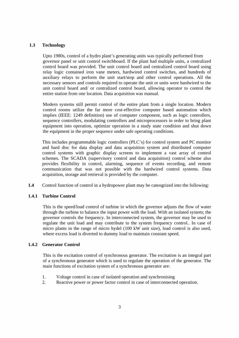
1.3 Technology
Upto 1980s, control of a hydro plant’s generating units was typically performed from governor panel or unit control switchboard. If the plant had multiple units, a centralized control board was provided. The unit control board and centralized control board using relay logic contained iron vane meters, hardwired control switches, and hundreds of auxiliary relays to perform the unit start/stop and other control operations. All the necessary sensors and controls required to operate the unit or units were hardwired to the unit control board and/ or centralized control board, allowing operator to control the entire station from one location. Data acquisition was manual. Modern systems still permit control of the entire plant from a single location. Modern control rooms utilize the far more cost-effective computer based automation which implies (IEEE: 1249 definition) use of computer component, such as logic controllers, sequence controllers, modulating controllers and microprocessors in order to bring plant equipment into operation, optimize operation in a study state condition and shut down the equipment in the proper sequence under safe operating conditions. This includes programmable logic controllers (PLC’s) for control system and PC monitor and hard disc for data display and data acquisition system and distributed computer control systems with graphic display screens to implement a vast array of control schemes. The SCADA (supervisory control and data acquisition) control scheme also provides flexibility in control, alarming, sequence of events recording, and remote communication that was not possible with the hardwired control systems. Data acquisition, storage and retrieval is provided by the computer.
1.4 Control function of control in a hydropower plant may be cateogrized into the following:
1.4.1 Turbine Control This is the speed/load control of turbine in which the governor adjusts the flow of water through the turbine to balance the input power with the load. With an isolated system; the governor controls the frequency. In interconnected system, the governor may be used to regulate the unit load and may contribute to the system frequency control.. In case of micro plants in the range of micro hydel (100 kW unit size), load control is also used, where excess load is diverted to dummy load to maintain constant speed.
1.4.2 Generator Control This is the excitation control of synchronous generator. The excitation is an integral part of a synchronous generator which is used to regulate the operation of the generator. The main functions of excitation system of a synchronous generator are: 1. Voltage control in case of isolated operation and synchronising 2. Reactive power or power factor control in case of interconnected operation.

4
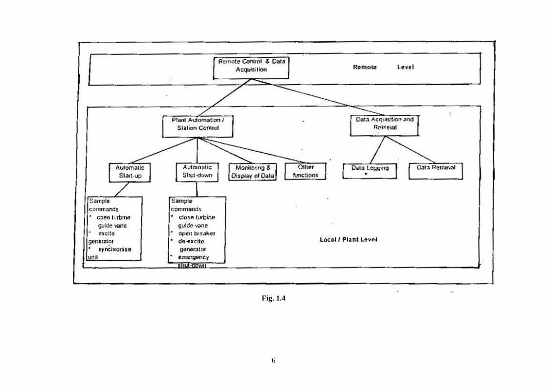
1.4.3 Plant Control Plant control deals with the operation of the plant. It includes sequential operations like start up of the machine, excitation control, synchronization, loading of unit under specified operating conditions, normal and emergency shutdown, etc. The mode of control may be manual or automatic and may be controlled locally or from remote location. Plant control usually include monitoring and display of the plant conditions. Schematic overview of the plant controls are given in Figure 1.4.
1.5 Considerations for Selecting Control System
Governor and control systems for small hydro units especially in developing countries have to be selected keeping in view the following. ii) Traditional mechanical flow control governor with mechanical hydraulic devices
is complex demanding maintenance and high first cost. Further performance requirements of stability and sensitivity i.e. dead band, dead time and dashpot time especially for interconnected units may not be possible with mechanical governors.
iii) The manpower as available for operation is unskilled and further adequate
supervision is not feasible.
iv) Load factors for stand-alone micro hydels are usually low which affects economic viability.
v) Cost of speed control and automation with electronic analaog flow control
governors, unit control and plant control is high. These systems require attended operation and are mostly based on large capacity hydro units. This is making most of the units very costly and uneconomical to operate. Experience in successful operation of analog electronic control system in India for SHP is not good.
vi) Electronic digital flow control governors can take up plant control functions.
vii) Flow control turbine governors are expensive and not recommended for small
hydro units in micro hydel range. Electronic load control governing system with water cooled hot water tanks as ballast loads for unit size upto 100 kW be used. This will make a saving of about 40% on capital cost. If the thyristor control (ELC) is used then the alternator needs to be oversized upto 2% on kVA to cope with the higher circulating current included. Accordingly, in case of small units upto 100-150 kW size elimination of flow control governors by digital shunt load governor (electronic load controllers) will make these units economically viable and properly designed will eliminate continuous attendance requirement.
viii) Data storage function can be added to the digital governors.
5
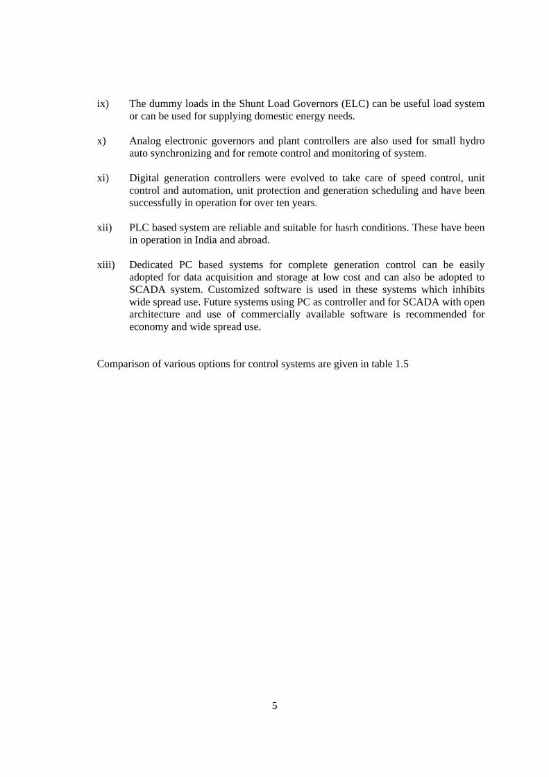
ix) The dummy loads in the Shunt Load Governors (ELC) can be useful load system or can be used for supplying domestic energy needs.
x) Analog electronic governors and plant controllers are also used for small hydro
auto synchronizing and for remote control and monitoring of system.
xi) Digital generation controllers were evolved to take care of speed control, unit control and automation, unit protection and generation scheduling and have been successfully in operation for over ten years.
xii) PLC based system are reliable and suitable for hasrh conditions. These have been
in operation in India and abroad.
xiii) Dedicated PC based systems for complete generation control can be easily adopted for data acquisition and storage at low cost and can also be adopted to SCADA system. Customized software is used in these systems which inhibits wide spread use. Future systems using PC as controller and for SCADA with open architecture and use of commercially available software is recommended for economy and wide spread use.
Comparison of various options for control systems are given in table 1.5
6
Fig. 1.4

7
1.5 Comparison of various options for control system, including turbine governing supervisory control and data acquisition
S. No.
Turbine Gov. and Controller Type
Unit size kW
Mode of operation
Suitability Cost including Gov. control, protection, SCADA data Aq., Storage and Retrieval (see note-1)
Recommendation
Remarks
Turbine Gov.
Unit control
Unit Prot.
Data storage and Retrieval
SCADA
Capital O & M
1. Mech. Flow control Gov. 50-100 Iso. At high extra cost Very high High without SCADA
Not recommendation
Grid 100-500 & above
Iso.
Grid
2. Load control governor 50-100 Iso. Suitable At extra cost Low Low Not considered Digital load control governor may be developed for SCADA
Grid
Do not available
100-500
Iso. See note 3
Grid
×
Not feasible
3. Analogue, Electronic Gov. & Plant Controller
50-100 Iso. Suitable At high extra cost Very high cost Not recommended
Grid
Above 100 Iso. High Moderate to high
Grid 4. PLC integrated controller
with SCADA by PC SHP 100 kW to 5 MW
Iso. Suitable Low Moderate Recommended
Grid
5. PLC digital governor with plant controller and SCADA with redundant PC
Above 5 MW
Iso. Suitable See not 2
High Moderate Recommended for units above 5 MW
Grid
6. Data Logger with PLC load controller
5 to 100 kW Iso. Data not available Low Moderate Recommended Grid
7. PC based integrated system for governing; plant control protection and metering
100 kW to 25000 kW
Iso. Suitable – Indigenous system not available Low Medium Recommended with high speed PC suitable for harsh area
Grid
Notes: 1. Cost normalized with main and backup SCADA system. 2. Dedicated digital controller for Gov. and plant control with PC based SCADA backup. 3. Recommended in conjunction with partial water flow control

8
1.6 Computer Based Control of Hydroelectric Station 1.6.1 Current practice for control of hydroelectric plants is based on the combination of
computer based and non-computer based equipment utilized for unit, plant and system control.
1.6.2 Methods of control:- Local, centralized and offsite modes of operation and supervision as
per IEC 62270 and IEEE 1010 and recognized by industry is given in table 2.1. Control as defined in the table 1.6.2 with details of control interface for plant equipment based on modern practice are discussed and control system design in accordance with standards mentioned. Table 1.6.2 – Summary of control hierarchy for hydroelectric power plants
Control category
Subcategory Remarks
Location Local Control is local at the controlled equipment or within sight of the equipment
Centralized Control is remote from the controlled equipment, but within the plant
Offsite Control location is remote from the project Mode Manual Each operation needs a separate and discrete initiation;
could be applicable to any of the three locations Automatic Several operations are precipitated by a single
initiation; could be applicable to any of the three locations
Operation (supervision)
Attended Operator is available at all times to initiate control action
Unattended Operation staff is not normally available at the project site
Method of control; control hierarchy extent of computerization recommend for different categories are discussed.
1.7 Computer Based Control System For Power Plant Above 5 MVA 1.7.1 Functional Capabilities
Functional capabilities summarised below may be provided to the extent economically feasible. i. Computer based automation system should permit operation of power plant,
switchyard, outlet works, Inlet valves etc. from a single control point. ii. Manual/Local control should be provided by equipment located near the
generating unit. The local unit computer (PLC) should be part of the equipment.

9
iii. Automatic unit start/stop control sequencing should be part of computer based automation. Automation system should include capability to provide diagnostic information so as to isolate the problem and get the unit on line as fast as possible.
iv. Auto synchronising should be computer based. There is no objection to provide synchronising function as internal to the automation system. Check synchronising relay should be provided for security.
v. The computer system shall optimise individual unit turbine operation to enhance unit operation in respect of following: a) Efficiency maximization - gate position, flow, unit kW output, unit
reactive power output. b) Minimization unit vibration or rouges running zone - gate position, unit
vibration.
CENTRALISEDCONTROL
UNIT 1LOCAL/MANUALCONTROL
USERINTERFACE
STATIONSERVICELOCAL CONTROL
UNIT 2LOCAL/MANUAL CONTROLINDIVIDUAL UNIT CONTROL
SWITCHYARD CONTROLSTATION SERVICE CONTROL& MONITORINGPLANT REAL POWER CONTROL& MONITORINGAUTOMATIC VOLTAGE CONTROLWATER & POWER OPTIMIZATIONAUTOMATIC GENERTAION CONTROLSWITCHGEAR AND RELAY STATUSREPORT GENERATIONDATA LOGGING/TRENDINGHISTORICAL ARCHIVING
SWITCHYARDCONTROL
SART/STOP SEQUENCINGSYNCHRONIZINGTRASHRACK CONTROLBLACK START CONTROLUNIT AUXILIARIES CONTROLGOVERNOR/EXCITATION CONTROL/STATUSUNIT LOAD CONTROLUNIT ANNUNCIATIONUNIT METERINGUNIT RELAY STATUSUNIT FLOW DATACONDITION MONITORING
POWER HOUSE
STATION OPTICALFIBRECOMMUNICATION NETWORK (DUAL)
USERINTERFACE
USERINTERFACE
USERINTERFACE
PLC
PLC
PLC
TO REMOTECONTROL
Fig. 1.7.1

10
LOCAL CONTROL SYSTEM
STATIONCOMMUNICATION LINK
LOCAL USER INTERFACE
PROTECTION SYSTEM
COMPUTER BASED CONTROL
BACKUPCONTROL
PROCESSINTERFACE
PROCESS(UNIT,SWITCHGEARGATES, ETC.)
Fig. 1.7.2
c) Minimization of cavitation: Gate position, flow, Hydraulic head, turbine manufacturers cavitation curve.
d) Black start control - this may including starting emergency generator. e) Centralised Control – Individual units, switchyard, station service control,
plant voltage/Var control, water and power optimization; Forebay level control.
vi. Data acquisition capabilities vii. Alarm processing and diagnostics viii. Report generation ix. Maintenance and management interface x. Data archival and retrieval xi. Data access xii. Operator simulation training xiii. Provision of frequency relay for this operation in stand alone or in an isolated
island for this purpose are should be made Relationship of local centralized and off site control function as per IEC: (62270-2004) guide in fig. 1.7.1 & 1.7.2. A typical block diagram of computer based control system for 2 x 10 MVA Mukerian Stage –II powerhouse with offsite control is attached 1.7.3 A provision for a programming station with back up for operation is also included as redundant system.

11
1.7.2 System Architecture, Communication and Databases
i. Open architecture system should be followed in accordance with IEEE-1249-1996. Interface or operating standards for the following shall be intimated and should comply with ISO/IEC 12119/IEEE 802.
Hardware interconnectivity Time stamping of data, Communications Operating system User Interface Data base
i. Each of these elements should be capable of being replaced by or communicate with
system elements provided by other vendors. ii. The scope of the bidder is not limited to the parts & components explicitly identified
here in and shall have to provide any and all parts/components needed to meet the functional requirements laid down herein or are necessary for satisfactory operation of the plant.
1.7.3 Control Data Networks
Local area networks (LANs) should be configured to IEEE 802.3 (Ethernet) standard. Commercially available software should be used as far as possible.
1.7.4 Man-Machine Interface (MMI)
The operator’s station of the station controller (SCADA system) should have an elaborate and friendly man-machine interface. A 19” or larger monitor should be provided for the display. Provision should be made for connecting a second colour monitor in parallel. The screen displays should be suitably designed to provide information in most appropriate forms such as text, tables, curves, bar charts, dynamic mimic diagrams, graphic symbols, all in colour. An event printer should be connected to PC of the SCADA system. Events should be printed out spontaneously as they arrive. Provision should be made to connect and use another printer simultaneously. Touch control screen, voice and other advanced modes of MMI are desired and should be preferred. The entire customization of software for MMI and report generation should be carried out. A windows based operating system should be preferred.

12
Fig. 1.7.3 – Redundant computer based control system for 2 x 10 MW Mukerian Stage II with remote control for stage I
(proposed by M/s BHEL)
13
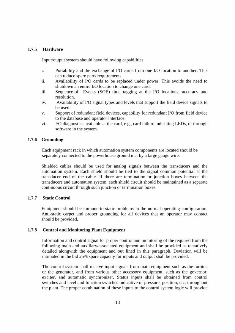
1.7.5 Hardware
Input/output system should have following capabilities. i. Portability and the exchange of I/O cards from one I/O location to another. This
can reduce spare parts requirements. ii. Availability of I/O cards to be replaced under power. This avoids the need to
shutdown an entire I/O location to change one card. iii. Sequence-of –Events (SOE) time tagging at the I/O locations; accuracy and
resolution. iv. Availability of I/O signal types and levels that support the field device signals to
be used. v. Support of redundant field devices, capability for redundant I/O from field device
to the database and operator interface. vi. I/O diagnostics available at the card, e.g., card failure indicating LEDs, or through
software in the system.
1.7.6 Grounding
Each equipment rack in which automation system components are located should be separately connected to the powerhouse ground mat by a large gauge wire. Shielded cables should be used for analog signals between the transducers and the automation system. Each shield should be tied to the signal common potential at the transducer end of the cable. If there are termination or junction boxes between the transducers and automation system, each shield circuit should be maintained as a separate continuous circuit through such junction or termination boxes.
1.7.7 Static Control
Equipment should be immune to static problems in the normal operating configuration. Anti-static carpet and proper grounding for all devices that an operator may contact should be provided.
1.7.8 Control and Monitoring Plant Equipment
Information and control signal for proper control and monitoring of the required from the following main and auxiliary/associated equipment and shall be provided as tentatively detailed alongwith the equipment and out lined in this paragraph. Deviation will be intimated in the bid 25% spare capacity for inputs and output shall be provided.
The control system shall receive input signals from main equipment such as the turbine or the generator, and from various other accessory equipment, such as the governor, exciter, and automatic synchronizer. Status inputs shall be obtained from control switches and level and function switches indicative of pressure, position, etc, throughout the plant. The proper combination of these inputs to the control system logic will provide

14
outputs to the governor, the exciter, and other equipment to start or shutdown the unit. Any abnormalities in the inputs must prevent the unit’s startup, or if already on-line, provide an alarm or initiate its shutdown. i. Generator ii. Generator field excitation equipment iii. Generator terminal equipment (Line and Neutral side) iv. Unit generator breaker equipment v. Turbine vi. Governor vii. Generator cooling viii. Service air ix. Service water x. DC power supply xi. AC auxiliary power supply xii. Water level monitoring xiii. Fire protection
1.8 Computer Based Control System For Powerhouses upto 5 MVA
Most of the small powerhouses in the range have the control room at the same level as the machine hall. Accordingly the unit control and supervisory control functions can be provided in the control room.
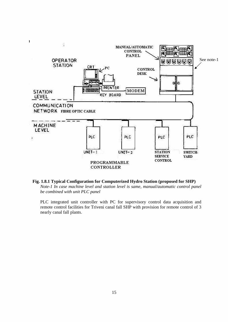
1.8.1 PLC Based System One PLC integrated controller per unit may be provided for unit control, governor control, unit control, supervisory control and data acquisition and remote control provision AVR and measuring units and auxiliaries. Separate controllers may be provided for switchyard, common auxiliaries etc. Remote/Supervisory control and data acquisition all the unit may be provided by one PC. The recommended control system is shown in drawing 1.8.1. Manual control facility is provided on PLC panel.
15
Fig. 1.8.1 Typical Configuration for Computerized Hydro Station (proposed for SHP)
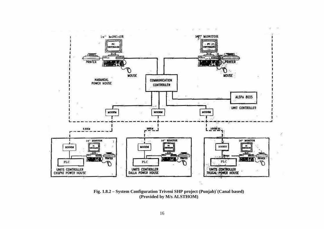
Note-1 In case machine level and station level is same, manual/automatic control panel be combined with unit PLC panel PLC integrated unit controller with PC for supervisory control data acquisition and remote control facilities for Triveni canal fall SHP with provision for remote control of 3 nearly canal fall plants.
See note-1
16
Fig. 1.8.2 – System Configuration Triveni SHP project (Punjab)`(Canal based)
(Provided by M/s ALSTHOM)

17
PC based system for unit control, governor control and other functions provided for Sobla powerhouse is attached as drawing 1.8.3 is a cheaper alternative but lacks redundancy which can be provided by spare cards for each type.
Fig. 1.8.3

18
1.8.2 PC based Integrated Generation Controller
Integrated governor and plant control system are discussed in guidelines for selection of turbine and governing system.
PC based integrated generation controller capable of following function was developed by M/s Digitek of USA and M/s Predeep Digitek in India for SHP.
• Governor speed control • Automatic sequencing for start up and shutdown including synchronizing • Automatic sequencing for emergency shutdown • Data recording and reporting • Alarm enunciators • Full remote control and monitoring • Control via terminal keyboard • Water level control • Flexible architecture • Modular card system • Ability to communicate with other microprocessor based equipment • Alarm and status logging • Data logging at user selected intervals • Event recording • Line protection- frequency and voltage • Generator protection - voltage, current, reverse power, differential, loss of field
Digitek USA integrated generation controller was installed in Sobla ( 2 x 3000 kW) SHP in U.P. Generator and line protection and meytreing was however provided by conventional meters and electromagnetic relays as shown in figure 1.8.3.
1.8.3 Micro processor based control for micro hydel
Electronic load controller and monitoring systems as recommended in micro hydel standards should be provided.
2 Protection & Metering 2.1 Protection System Forced outage due to faults in power system components e.g. generating unit, transformer bus bars, sub station and transmission lines affect reliability of power supply. Increasing spare capacity margins and arranging alternative circuits to supply loads are provided to take care of such failures. For minimum isolation following a break down the system is divided into zones controlled by switchgear in association with protective gears. Switchgear is designed to interrupt normal and fault current. Protection gear must recognize an abnormal condition and operate to secure its removal with the minimum disturbance to normal system operation. Protective gear

19
defines all equipment necessary for recognizing; locating and initiating the removal of a fault or abnormal condition from the power system and includes a relay or group of relays and accessories to isolate electrical installation (machine, transformer etc.) or to activate a signal. Accessories are current and voltage transformers, shunts, d. c. and a. c. wiring and auxiliary devices necessary to secure successful operation. 2.2 Protective Relay Technology Protective relay technology has changed significantly in recent years. Induction disk relays for each individual protective function were normally used. Individual solid state static relays for protective function were introduced in the decade 1980-1990 and IS 3231-1965 was accordingly revised in 1987. 2.2.1 Microprocessor based Multifunction Relays: Microprocessor based multi function
relays are now being introduced. Advantage claimed for these relays are as follows: i) Self-monitoring of operating status on continuing basis and to alarm when to function. ii) Multiple protective functions in one relay reduces panel space and wiring end. iii) Self calibration by software programming iv) Programmable set point by software programming Microprocessor relaying has gained widespread acceptance among both utilities and consumers. The relay functions are the same as those in electromechanical and solid-state electronic relaying, but microprocessor relays have features that provide added benefits. Microprocessor relays may have some disadvantages, however, so that there are additional considerations when these are applied for protection in SHP. 2.2.2 Benefits of Microprocessor Relays: The benefits of microprocessor relays include the
ability to combine relay functions into economical unit. Where an electromechanical overcurrent relay may be only be a single phase device, a microprocessor relay will often include three phases and a neutral. It could also include reclosing, directional elements, over/under voltage, and over/under frequency. A microprocessor generator relay could include differential, overcurrent, negative, sequence, frequency, voltage, stator ground, and other protective functions. Similarly, a microprocessor transformer relay might combine differential and overcurrent protection. A transmission line relay could combine multiple zone phase and ground distance elements, over current fault-detectors, pilot scheme logic, and reclosing. An electromechanical scheme will normally consist of individual relays for each zone of phase and ground protection, separate fault-detectors, and additional relaying for pilot scheme logic. These same devices can include nonrelaying functions such as metering, event recording, and oscillography. All of these functions are contained in an enclosure that requires less space than the combination of elays and other devices they duplicate.
A microprocessor relay has self-monitoring diagnostic that provide continuous status of relay availability and reduces the need for periodic maintenanace. If a relay fails, it is typically replaced rather than repaired. Because these relays have multiple features,
20
functions, increased setting ranges, and increased flexibility, it permits stocking of fewer spares.
Microprocessor relay also have communication capability that allows for remote interrogation of meter and event data and fault oscillography. This also permits relay setting from a remote location. The relays have low power consumption and low CT and VT burdens. They also increase the flexibility of CT connections. For instance, microprocessor transformer differential relays can compensate internally for ratio mismatch and the phase shift associated with delta-wye connections.
All of these features have economic benefits in addition to the lower initial costs and potentially reduced maintenance costs that microprocessor relays have when compared to individual relays.
2.2.4 Disadvantages: The operating energy for most electromechanical relays is obtained from
the measured currents and/or voltages, but most microprocessor relays require a source of control power. Another disadvantages is that the multifunction feature can result in a loss of redundancy. For instance, the failure of a single-phase overcurrent relay is backed up by the remaining phase and neutral relays. In a microprocessor scheme, the phase and neutral elements are frequently combined in one package and a single failure can disable the protection. Similarly, a microprocessor generator/transformer package that has both differential and overcurrent relaying provided less redundancy than a scheme comprising separate relays. The self-disgnostics ability of the microprocessor relay, and its ability to communicate failure alarms, mitigates some of the loss of redundancy. It may also be economical to use multiple microprocessor relay.
Microprocessor relays require more engineering in the application and setting of the relay though less work in the panel design and wiring. The increased relay setting flexibility is accompanied by an increase in setting complexity that requires diligence to avoid setting errors. Also, some relays have experienced numerous software upgrades in a short period of time. Microprocessor relays have relatively shorter product life cycles because of the rapid advance in technology. As a result, a specific microprocessor relay model may only be available for a relatively short period of time. As a failure may require replacement rather than repair, it may not be possible to use an exact replacement, which may require more engineering and installation work. Although less frequent testing may be required, when it is, it requires a higher level of training for the technician and more test equipment than is normally used with electromechanical relays in order to obtain the full benefit of all the features of the microprocessor relay. The self-monitoring capability of these relays is only effective if the alarm output can be communicated to a manned location such as a control center. Also, the remote communication ability assumes there is a communication channel available to the relay.
2.2.5 Interconnection of SHP with Grid
A similar issue exists concerning the communication capability of microprocessor relays in SHP. Both the utility and the consumer can benefit from the communication capability.

21
In particular, the recorded history of events can be very useful in analyzing relay operations after a fault. However, for both to communicate directly with the relay will require special considerations. Both the utility and the consumer may be required to purchase software license for the communication software if that software is propriety. Also, they will both need to maintain the same versions of the software. The communication settings, such as modem baud rate, will have to be mutually agreed on. Some relays have security passwords, which restrict access. There may be one password to permit read only access to meter and event records and a different password to make changes. Although both parties may have read only access, ideally only one party should have the necessary access to make setting changes.
2.2.6 Protection relays for SHP
i) The application of relays must be coordinated with the partitioning of the electrical system by circuit breakers, so that least amount of equipment is removed from operation following a fault, preserving the integrity of the balance of the plant’s electrical system.
ii) Generally, the power transmitting agency protection engineer will coordinate with the utility protection engineer to recommend the functional requirements of the overlapping zones of protection for the main transformers and high voltage bus and lines. The utility protection engineer will determine the protection required for the station service generators and transformers, main unit generators, main transformers, and powerhouse bus.
iii) Electromechanical protective relays, individual solid state protective relays, multi-function protective relays, or some combination of these may be used as appropriate for the requirements.
iv) individual solid state protective relays and/or multifunction protective relays offer a single solution for many applications plus continuous self diagnostics to alarm when unable to function as required. Multi-function protective relays may be cost-competitive for generator and line protection when many individual relays would be required.
v) When multi-function relays are selected, limited additional backup relays should be considered based upon safety the cost of equipment lost or damaged, repairs and the energy lost during the outage or repairs if appropriate.
vi) When redundancy is required, a backup protective relay with a different design and algorithm should be provided for reliability and security.
vii) Generators, main transformers, and the high voltage busbar are normally protected with independent differential relays (above 1000 kW unit size).
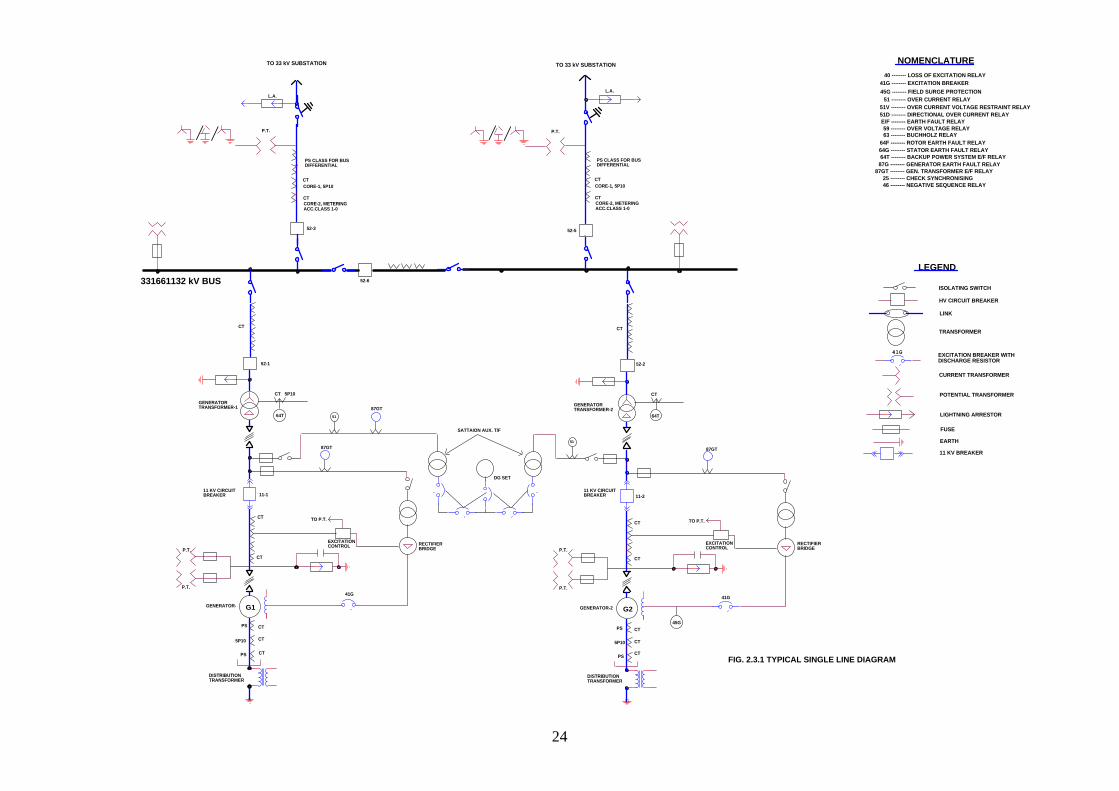
2.3 Monitoring and Protection for generating Units above 3 MW and upto 25 MW
The following protection may be provided by using integrated numerical generator protection relay on generator, generator transformers and feeders. Back up electromagnetic relays with instrument transformers may be provided as mentioned below:

22
2.3.1 Generator
1. Generator Differential Protection (87G) 2. Negative Phase Sequence (46) (Phase Unbalance) 3. Generator Reverse Power Protection (32) 4. Voltage Restrained Over Current Protection (51V) 5. Stator Earth Fault Protection (64 G) 6. Loss Of Excitation Protection (40) 7. Over /Speed (electrical) Protection (12G) 8. Rotor Earths Fault Protection (64R) 9. Over Voltage Protection (59) 10. Fuse failure Protection (97) on PTS 11. Under voltage (27) 12. Check synchronizing
Following additional back up electromagnetic relays from different set of CTs and PTs be also provided. 1. Voltage restraint overvurrent relay 2. Stator earth fault
Following Mechanical Protections are proposed
1. Embedded Temperature detector (PT-100) in stator core and in bearing for indication, alarm, recording and shut down of the unit.
2. Governor oil pressure low. 3. Over speed mechanical for normal and emergency shut down.
2.3.2 Power Transformer
1. Generator transformer differential protection ( 87 GT) 2. Over current and earth fault protection with high set Inst. Element (50/51,64) 3. Stand by earth fault protection (64GT) on 33 kV side. 4. T/ F Winding Temperature High Alarm/ Trip (49T) 5. T/ F Oil Temperature High Alarm/ Trip (38T) 6. Buchholtz relay
Following additional back up electromagnetic relays from different set of CTs and PTs be also provided.
2.3.3 33 kV Line Protection
1. Phase comparison/distance relays for 66 kV and above 2. Digital Directional over current and earth fault relay with high set unit
(50/51,64). 3. Under voltage (27)
23
4. Over voltage (59) 5. Over/ under frequency (81) 6. Reverse Power Relay 7. Check Synchronizing
Back up electromagnetic, Directional over current and earth fault relay with high set unit 2.3.4 Bus Zone Protection Differential Bus Zone Protection with check features are proposed. 2.3.5 Station Transformer Protection
1. Fuse set on 33 kV side. 2. Digital over current and earth fault relay with high set unit on B.T. side. (50/51, 64).
2.3.6 Metering System
Power generated shall be metered at generator terminal through metering CT and PT. The power transferred to 33 kV feeder shall also be metered though CTs and PT. Following metering equipments shall be provided on relevant panels.
1. kW meter 2. kWh meter 3. kVA meter 4. Ampere meter 5. Voltmeter 6. Power factor meter 7. Frequency/speed meter 8. Temperature meters.
A typical single line diagram is shown as figure 2.3.1 and Unit Metering and relaying is shown as figure 2.3.2.
24
HV CIRCUIT BREAKER
LEGEND
NOMENCLATURE
LINK
LIGHTNING ARRESTOR
41G
POTENTIAL TRANSFORMER
40 -------- LOSS OF EXCITATION RELAY
FUSE
CURRENT TRANSFORMER
TRANSFORMER
EARTH
ISOLATING SWITCH
EXCITATION BREAKER WITHDISCHARGE RESISTOR
52-3
331661132 kV BUS
11 KV BREAKER
52-5
DISTRIBUTIONTRANSFORMER
CT
CT
G1
PS
GENERATOR-
52-1
GENERATORTRANSFORMER-1
11-1
DISTRIBUTIONTRANSFORMER
G2GENERATOR-2
52-2
11-2
P.T.
P.T.
P.T.
41G
41G -------- EXCITATION BREAKER45G -------- FIELD SURGE PROTECTION
51 -------- OVER CURRENT RELAY51V -------- OVER CURRENT VOLTAGE RESTRAINT RELAY51D -------- DIRECTIONAL OVER CURRENT RELAYE/F -------- EARTH FAULT RELAY59 -------- OVER VOLTAGE RELAY63 -------- BUCHHOLZ RELAY
64F -------- ROTOR EARTH FAULT RELAY64G -------- STATOR EARTH FAULT RELAY64T -------- BACKUP POWER SYSTEM E/F RELAY
87G -------- GENERATOR EARTH FAULT RELAY87GT -------- GEN. TRANSFORMER E/F RELAY
25 -------- CHECK SYNCHRONISING46 -------- NEGATIVE SEQUENCE RELAY
45G
PS
CT
CT5P10 5P10
PS
PS CT
CT
CT
CT
CT
EXCITATIONCONTROL
CT
CT
RECTIFIERBRIDGE
L.A.
CTCORE-1, 5P10
P.T.
64T
CT
64T
CT 5P10
GENERATORTRANSFORMER-2
RECTIFIERBRIDGE
CT
11 KV CIRCUITBREAKER
CORE-2, METERINGCT
41G
TO 33 kV SUBSTATION TO 33 kV SUBSTATION
52-6
ACC.CLASS 1-0
L.A.
87GT51
87GT51
87GT
P.T. P.T.
TO P.T.
EXCITATIONCONTROL
TO P.T.
///
DG SET
SATTAION AUX. T/F
PS CLASS FOR BUSDIFFERENTIAL
CTCORE-1, 5P10
CORE-2, METERINGCT
ACC.CLASS 1-0
PS CLASS FOR BUSDIFFERENTIAL
/ //
11 KV CIRCUITBREAKER
FIG. 2.3.1 TYPICAL SINGLE LINE DIAGRAM

25
..
.
...
41G
THYRISTORBRIGES
S.S.
DISTRIBUTIONTRANSFORMER
RESISTOR
64G
TURBINEGUIDER.T.D.
BEARING
A3
PF
VSV KW
V
L
RUN INC
SYN
SYN. PANEL
RECT
63QTH
38THTTHERMOSTAT
R.T.D.
GENERATOR GUIDE& THRUST BEARING
87G
86 EA
RATED 15 SEC.
TURBINE SPEEDNO LOADAND ALARM
TURBINE SHUTDOWN WITH ALARM
MISC
38 63 48
63TX
63T
FIRSTSTAGEALARM
86 EB
, PENSTOCK GATE AND ALARMCLOSURE
RECTIFIERTRANSFORMER
86 MA
86 MB
59
LDC
VAR.COMP
FROM EXCITOR 2
MANNUALKVAR
TO 86 EB
51 EX
38-2 5P 10
CT
11 KVGENERATORBREAKER
GENERATORS
TRIP 52-1, & 41G
AND ALARM
MISC
S.S.
S.S..
L
V
F F
STATICEXCITATIONVOLTAGEREGULATORAND CONTROL
33 K.V. BUS
11-1
S.S.
SYNCHRONISINGSOCKET
G
SYNCH.
DOWN
41 GTRIP 52-1 &
EQUI
PMEN
TFR
OM
BAT
TERY
31
FIEL
DFL
ASHI
NG
38QB
39V33AB
26G63FG
71QBH/L
71QBH/L
26GS
C.T.
LINK
60
BLOCKS 50/51V& 40 ON LOSSOF RELAYPOTENTIAL
SURGEARRESTOR
51V 46
59
64F
86 EBTO
V
OER
A12
38TG
26AO/AI
38QB
33CW/80CW
41 GTRIP 52-1 &
TURBINE SHUT41 GTRIP 52-1 &
DOWNTURBINE SHUT
PTPT
FF
PSCT
2.COMMON TRIPPING RELAYS FOR SIMILAR
RELAYS
TEMPERATURE
3.TRIPPING BLOCK DIAGRAM DOES NOT
DETECTORS)
EQUIPMENT ORDERED
4.DETAILS OF R.T.D. (RESISTANCE
.
RELAYS FOR DISCRIMINATION OF FAULTS ARE
FUNCTIONS WILL BE PROVIDED WITH LOCK
FIRST STAGE ALARMS
(C) TURBINE GUIDE BEARING - 2 NO.
(A) GENERATOR STATOR WINDINGS - 12 NO.
ACTUAL
INDIVIDUAL CIRCUITS OF COMMON TRIPPINGPROPOSED TO BE PROVIDED IN THE
(B) GENERATOR THRUST BEARING - 2 NO.
OUT FACILITIES, SIGNAL TYPE CURRENT
1.THE SCHEME MAY BE MODIFIED TO SUIT
INCLUDE
ARE AS UNDER :
NOTES
5. UNIT-2 IS SAME AS UNIT-1
OVER VOLTAGE RELAY
LCD
SUPERVISORY
51 H
27L
RELAY
VAR METER
62L62
64F
WATT HOUR METER
81HH.V. SYSTEM STAND BY GROUND FAULT64T
81L
50/51DN
INSTANTANEOUS TIME OVERCURRENT
ANNUNCIATOR RELAY
A AMMETER
94
59
WM
INSTRUMENTRECT
TZ
VARM
86H
LINE DROP COMPENSATION
51 EX
66 K.V. SYSTEM
30
86 EX
SUPV.
GENERATOR TRANSFORMERDIFFERENTIAL RELAY
LOCKOUT RELAY
V
WHM
LOCKOUT RELAY
UNDERVOLTAGE RELAY
LOW FREQUENCY RELAY
DIRECTIONAL OVERCURRENTAND GROUND FAULT RELAY
PHASE RELAY
EXCITERS
OVER EXCITATION RELAY
52-1
PAR
GENERATOR FIELD BREAKER
FM
WATT METER
GENERATOR TRIP RELAY
TIMING RELAY
TRANSDUCER
87GT
66 K.V. BREAKER
OER
INSTANTANEOUS TIME OVERCURRENT
FREQUENCY METER
PARALLEL COMPENSATION
GROUND VOLTAGE RELAY - FIELD
COMP
TEMPERATURE MEASURINGAND RECORDING
VOLT METER
VS
-DO-
41G
METERING
HIGH FREQUENCY RELAY
EXCITATION RELAY31
VOLT METER SWITCH
25
CENTRIFUGAL SPEED SWITCH
CHECK SYNCHRONISING RELAY
12
63 T63 TX
LOCKOUT RELAY MECH. GROUP "A"
GENERATOR DIFFERENTIAL RELAY
LOCKOUT RELAY ELECT. GROUP "A"LOCKOUT RELAY ELECT. GROUP "B"
LOCKOUT RELAY MECH. GROUP "B"
GROUND VOLTAGE RELAY - STATOR64G
87G86 MB
86 EB86 EA
86 MA
38THT THRUST BEARING TEMPERATURE38QB BEARING OIL TEMPERATURE
71QBH/L BEARING OIL LEVEL(HIGH/LOW)
63QTH THRUST BEARING HIGH PRESSURE OILSYSTEM START INTERLOCK/FAILURE A
63FG FIRE EXTIGUISHING SYSTEM OPERATIO
26G TEMPERATURE DETECTORS FORFIRE PROTECTION SYSTEM
33AB AIR BRAKE POSITION INDICATION
26GS STATOR WINDING TEMPERATURE
26AU/AI AIR COOLER (OUTLET/INLET)AIR TEMPERATURE
33CW/80CW COOLING WATER VALVE POSITION/FL
38GT GUIDE BEARING TEMPERATURE
REVERSE POWER RELAY32
38 BEARING TEMPERATURE DEVICE
40 FIELD FAILURE RELAY
NEGATIVE PHASE SEQUENCE RELAY4647 PHASE SEQUENCE CHECK RELAY
(FOR SYNCHRONIZING)INCOMPLETE SEQUENCE RELAY48TARNSFORMER OVERCURRENT RELAY50/51 T
51V INSTANTANEOUS OVERCURRENTWITH VOLTAGE RESTRAINTRELAYVOLTAGE BALANCE RELAY60GOVERNOR LOW OIL PRESSURE SWITC63
RELEASE CO2,
TO 86 EB
52-1 BREAKER
63T
38T
5P10CT
TRANSFORMERGEN.
64T
12G
12G ELECTRICAL OVERSPEEDC RELAY
38-2
65SN65SL
SOLENOID SPEED NO LOADSOLENOID SHUT DOWN
LINK
5P10
CT
12G12
MAIN TANK OVER PRESURE SWITCHAUXILIARY RELAY
PS
CT
CT
CT
NOMENCLATURE
45F FIELD SURGE PROTECTION
64F ROTOR EARTH FAULT RELAY
FM
KWH
50/51
40 32
2547
27V
87 GT
87 GT
250 kVA
51/64 C.T.
11/.415 kV
EX.CONTROL
TO P.T.
87T
TRANSFORMER DIFFERENTIAL RELAY87T
FIG. 2.3.2 TYPICAL UNIT METERING SINGLE LINE DIAGRAM121
2

26
2.4 Monitoring and Protection for Generating Units above 100 kW and upto 3 MW
Monitoring and protection with two levels of protection and recommended as follows in SHP as per IEC-1116.
2.4.1 Turbine In principle, two levels of protection can be specified: alarm and tripping. Elements to be considered are: (a) speed of rotation; (b) oil level in the bearings; (c) circulation of lubricant; (d) oil level of the governor system; (e) oil level of the speed increasers; (f) bearing temperature; (g) oil temperature of the governor system; (h) oil temperature of speed increasers; (i) oil pressure of the governor system; (j) circulation of cooling water Immediate tripping is required for items a), c), i) and j). Items b), d), e), f), g) and h) may have an alarm annunciated first if the station is manned allowing corrective action to be taken, but in any case, in the absence of corrective action, tripping will eventually follow. In some cases, braking is used to reduce the time to standstill. It is recommended that two independent overspeed shut-down devices be used on larger units which might not be designed for continuous runaway.
2.4.2 Generator The following are normally monitored. (a) stator temperature; (b) overcurrent (stator and rotor); (c) earth fault with current limits (stator and rotor); (d) maximum and minimum voltage; (e) power reversale) (f) over/under frequency; (g) oil level in the bearing sump; (h) bearing temperature; (i) cooling air temperature.
27
Immediate tripping is required for items (b), (c), (d), (e) and (f). Items (a), (g), (h) and (i) may have an alarm annunciated if the station is manned allowing corrective action to be taken, but in any case, in the absence of corrective action, tripping will eventually follow. Depending on the individual case, heating equipment to prevent condensation may be required. It is advisable to consider differential protection when the size of the generator and/or its environment justifies it. The instruments and devices generally recommended for monitoring and protection are as follows: voltmeter, ammeter, wattmeter, energy meter, power factor meter, tachometer, hours of operation counter, synchronizer, water-level and/or pressure indicator, turbine opening indicator, emergency stop device, short-circuit current protection, overcurrent protection, reverse power relay, frequency monitor, voltage monitor, bearing monitor.
Metering and Relaying single line for typical SHP of various system is shown in. Monitoring and control and data acquisition system (SCADA system) can be a part of the P.C. based digital governor and generation control equipment. Provision of data storage of one month with 16 MB of Ram memory and a 540 to 850 MB Hard Drive as part of the PC based governing and control system should be provided. This data could be retrieved on a floppy drive after one month for examination. As the communication links develop the data can also be transmitted via a Modem to a remote point for examination and supervisory control.
Typical single line diagram for synchronous generators is attached as figure 2.4.1 and Asynchronous generator as figure 2.4.2.
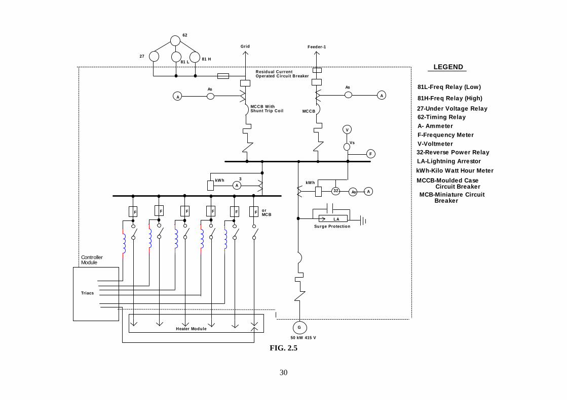
2.5 Monitoring and Protection for Micro hydel systems
Monitoring and Protection as recommend in micro hydel standards be provided. Micro hydel (100 kW) may be provided with series overcurrent and short circuit protection (M.C.C.D); Residual current breakers for earth fault protection and surge protection equipment. A typical 50 kW micro hydel single line diagram showing protection is attached as Fig. 2.5. MCCB could be provided with shunt trip coil for providing over voltage; overcurrent and nonbalance load trip as a part of shunt load governor if possible.

28
G
64G
VOLTAGE REGULAION
EXCITATION
51V
32 kW A
kVAR
5927V4981
V
STATION SUPPLY FOR AUXILIARY
SYNCHRONIZER
V
27 Under voltage relay49 Under frequency81 Over frequency relay32 Reverse power relay51V Overcurrent voltage
restraint relay64G Stator earth fault relay46 Phase Unbalance relay 25 Check Synchronizing Relay64F Rotor Ground fault relay51F Field excitation Overcurrent
Protection
FIG. 2.4.1 Single Line Diagram - Synchronous Generator
See note-2
v
64F
51F
kWh46
LA
25
50 51
BRUSHLESS EXCITATION
(SEE NOTE -3)
SEE NOTE-4
V Voltage
A Current
kW Power
kVAr Reactive power
Energy
Indication
NOTE:1. Generator circuit breaker may be installed on low voltage side of the transformer 2. Distribution transformer type earthimg may be provided if power supply at generation voltage is not required. 3. May use static excitation esp. for larger units.4. Lightning arrestor at transformer terminals may be omitted for single unit SHP5. Station service transformer may be tapped from generator leads if LV side breaker is provided. 6. Differential protection may be provided for unit sizes above 750
kW and for units below this size if environment justified
kWh
See note 5
LA
See note 1
Synchronous Generator

29
G
64G
3250/51 kWh
STATION SUPPLY FOR AUXILIARIES
50
27 Under voltage relay49 Under frequency81 Over frequency relay32 Reverse power relay51V Overcurrent voltage
restraint relay64G Stator earth fault relay46 Negative sequence relay
Protection
kW A
27
kVAr
V
V
PT 33/110
EARTHING RESISITOR
V Voltage
A Current
kW Power
kVAr Reactive power
kWh Energy
To Existing 33 kV line (300 m)
Lightning Arrestor
Indiaction
FIG. 2.4.2 Single Line Diagram - Asynchronous Generator
NOTE:1. The circuit breaker may be installed on LV side of transformer2. Capacitor bank may be provided on HV side before HV breaker so that it is switched on and off with breaker3. Lightning arrestor on transformer terminals may be omitted for single phase SHP.
30
kWh
32 A
Surge Protection
LEGEND
81L-Freq Relay (Low)
81H-Freq Relay (High)27-Under Voltage Relay62-Timing Relay
LA
Heater Module
Triacs
ControllerModule
F F F F F F
As
Vs
MCCB WithShunt Trip Coil MCCB
81 L
A
27
V
62
81 H
Residual CurrentOperated Circuit Breaker
Feeder-1Grid
A3kWh
A- AmmeterF-Frequency MeterV-Voltmeter32-Reverse Power RelayLA-Lightning ArrestorkWh-Kilo Watt Hour MeterMCCB-Moulded Case Circuit Breaker
G
50 kW 415 V
As
A
As MCB-Miniature Circuit Breaker
F
orMCB
FIG. 2.5