STANDARDS & GUIDELINES - Memphis · STANDARDS & GUIDELINES City of Memphis Engineering Division ......
47
STANDARDS & GUIDELINES City of Memphis Engineering Division Land Development September 30, 2016
Transcript of STANDARDS & GUIDELINES - Memphis · STANDARDS & GUIDELINES City of Memphis Engineering Division ......

Page 0 of 19
STANDARDS & GUIDELINES
City of Memphis
Engineering Division
Land Development
September 30, 2016

Table of Contents
I Introduction & General Background ..................................................................................2
II Development Applications ..............................................................................................3
III Submittal Requirements.................................................................................................5
APPENDIX
Land Development Transmittal Form
City of Memphis Title Block (example)
Site Plan Checklist
Street Plan and Profile Sheet Checklist
Off-Street Drainage Checklist
Off-Street Sanitary Sewer Checklist
Outfall or Sewer Extension Plan and Profile Sheet Checklist
Grading & Drainage Plan Checklist
Grading & Drainage General Notes
Drain Pipe Data Table
Drain Structure Data Table
Erosion Control Plan Checklist
Post Construction Runoff Control Plan Checklist
Sewer Plan Checklist
Sewer Plan Notes
Traffic Control Plan Checklist
Traffic Control Plan Notes & Guidance
Signing and Striping Plan Checklist
School Zone Flasher Signal Checklist
Traffic Signal Plan Checklist
Easement Plat Checklist

2
I Introduction & General Background
The City of Memphis, Engineering Division (City Engineering) welcomes the opportunity to serve the citizens of our community. This document serves as a means to communicate our process related to land development, and the role that City Engineering plays in that process. The Land Development Office (LDO) is a department under City Engineering that specifically works with the Memphis and Shelby County Office of Planning & Development (OPD) to ensure that all developments adhere to City standards and meet the requirements set forth for public improvements. Contact information for the LDO is as follows:
Title: Land Development Coordinator
Address: 125 North Main Street, Suite 644 Memphis, TN 38103 Phone: 901.576.6704
Disclaimer: This document is provided as a general guideline for the plan submittal process. Information contained herein is for the designer’s aid. The intent of this document is to provide information and guidance only. The engineer is ultimately responsible for the accuracy and completeness of the design submittal. Standard City of Memphis Construction Specifications, the Unified Devlopment Code (UDC), and the City of Memphis Storm Water Management Manual all provide exhaustive information pertaining to design requirements.

3
II Development Applications
A. When is it necessary to submit plans to Land Development?
Plans must be submitted to the Division of Engineering, Land Development Office (LDO) for
review of:
Any work within or upon City of Memphis property or street right-of-way (ROW), or within
a City easement (drainage, sewer, etc.)
Any work that directly affects traffic within the City’s ROW
Any work that may cause an increase of stormwater runoff to City stormwater facilities
or downstream properties (refer to Memphis and Shelby County Storm Water
Management Manual (SWMM)).
Stormwater runoff from projects larger than one acre, or within a drainage basin deemed a
“Sensitive Drainage Basin” by the City, or in the Fletcher Creek Overlay District must be
addressed with stormwater detention facilities, unless a request for a stormwater detention
waiver has been filed and approved by City Engineering (SWMM Volume 1, Section 6.6). This
issue is discussed in further detail in this document.
Projects that must go through the Land Development Plans Review process should fall into one
of the following categories.
Memorandum of Conformance (MOC)
Administrative Site Plan Review (ASPR)
Street Cut Permit (SCP)
Standard Improvement Contract (SIC)
Plat Re-Recording
Easement Plat
Encroachment Agreement
ROW Dedication
Street & Alley Closure
Underground Fiber/Cable Plans
Monitoring Well
All submittals must be accompanied by a completed Land Development Transmittal Form (see
Section 4 for Standard Form).
A Street Cut Permit is filed for work within City ROW/easements, not exceeding construction
cost of $25,000. Click here for the Street Cut Permit procedures. For projects exceeding
$25,000, a Standard Improvements Contract must be executed between the owner/developer
and the City, and approved by City Council.
Curb Cut Permit applications (for work involving only a new commercial drive connection) should
be submitted directly to City of Memphis Traffic Engineering (901.576.6710).
Sidewalk Permits (for work involving only minor sidewalk repair/pour) and Residential Driveway
Permits can be obtained from the City of Memphis, Construction Inspections Office at
901.636.2462.

4
B. How do I get an MOC?
MOC’s are issued by OPD upon submittal of the Final Plat. Please call 901.576.6601 with
questions.
C. How do I get an ASPR?
Plans for developments considered by the applicant as a “use by right” (i.e., already properly
zoned, platted, etc.) should be submitted to the Memphis/Shelby County Office of Construction
Code Enforcement (OCCE). OCCE will coordinate with LDO as needed to determine whether
plans will be reviewed by City Engineering. Please call 901.222.8300 with questions.
D. What fees are required for plans review?
The City has established a process for review that ensures all applicants are treated
equitably. The base fee for Civil Engineering Plans (site construction drawings) review or
Final Plat/Plan review (when a stand-alone plat is submitted) is $525 for the first 3 reviews
and $250 for each additional review. When a Final Plat is submitted in conjunction with
plans, no additional fee is required for review of the plat.
The review fee for Street and Alley Closure plats, Easement Plats, Encroachment Plats, and
Plat Re-records is $250.
Street Cut Permit fees for work within the public ROW are calculated by Land Development
near completion of the plans review process.
Curb Cut Permit fees will be calculated by Traffic Engineering on a case by case basis.
Sidewalk Permit and Residential Driveway Permit fees are set by City Inspections.
For review of Fiber Optic Permits, typically a $750 base review is required for projects less
than 1 mile in length. Additionally, a fee of $1 per foot is assessed by City Inspections prior
to construction to cover the permit fee for such projects. For Fiber Optic projects over 1 mile
in length, fees for review, permit, and construction inspection are assessed on a case-by-
case basis.
For more detailed information regarding fees for review, refer to City of Memphis Ordinances,
available at: (https://www.municode.com/library/tn/memphis/codes/code_of_ordinances?nodeId=TIT2AD_CH2-22DIEN)
E. What will be required at the end of construction to close out the project and get bonds released?
Prior to release of Developer’s bonds:
(1) the City must conduct final inspection and provide report, AND
(2) the owner/developer must have public infrastructure and/or detention facilities
surveyed for as-built conditions. The consultant will submit revised/corrected mylars. Bonds
can be released when the final inspection is approved and revised mylars are signed by the City
Engineer. Additional information regarding Record Drawings is provided in Section III.C.13.

5
III Submittal Requirements
A. Items to be submitted
All plans that are submitted to Land Development must contain:
Transmittal Form (Click here for City of Memphis Standard Transmittal Form)
CD or thumb drive with all plans being submitted in pdf format for original and subsequent
submittals.
Plans – 5 sets of 24”x36” sheets with City Title Block (see Section 5); additional sets may
be requested based on complexity of the project.
Final Plat/Plan or Site Plan – Plats to be recorded are to be submitted on 20”x24” sheets,
and Site Plans on 24”x36”.
Plans Review Fees (see Section II.D)
B. Plans to be submitted
1. As applicable, please include the following sheets with your submittal:
Table 1 – Plans Requiring City Engineer Signature
Sheets must be on City Title Block and
include signature line for City Engineer(s)
Sheets not signed by City Engineer
a. Site Plan or Final Plat (Site Plan will not be signed
by City Engineer if accompanied by Final Plat)
b. Grading & Drainage (including detention and off-
street drainage)
c. Erosion Prevention & Sediment Control Plan
(EPSC)
d. Post Construction Runoff Control Plan (PCRC)
e. Sewer Plan – both public and private
f. Plan & Profile (individual sheets for Roadway,
Sewer, Drainage) – required if any public
improvements are affected unless it’s a rural or
industrial section of roadway
g. Traffic Control for work zones
h. Signage & Striping (permanent)*
i. Signalization*
j. Details –City of Memphis Standards (see Section
4) or custom details for public infrastructure
a. Title Sheet with Index - required for all projects
b. Existing Conditions
c. General Notes sheet
d. Site Layout Plan
e. Details – not per City standard and for private
infrastructure
f. Demolition Plans
*City Traffic Engineer signs these sheets.
2. All plan sets submitted under MOC’s must include a Final Plat. Requirements for submittal
of a plat to OPD for approval are found in the Memphis and Shelby County Unified
Development Code. This document can be found at: http://www.shelbycountytn.gov/DocumentCenter/View/22306
3. Please see Table 2 below to determine which plans you are required to submit. All sheets
must be 24”x36”, signed and sealed by a TN Licensed Professional Engineer, with City of
Memphis Title Block and signature lines for City Engineers as applicable (Click here for City
of Memphis Title Block sample). Watermarks or stamps for “PRELIMINARY” or “NOT FOR
CONSTRUCTION” are acceptable during review.

6
Table 2 – Plan Sheet Submittal Matrix
Plan Sheet Name Sheet required if one of the conditions in the 3 columns below are
proposed for your project:
a. Site Plan Required for all submittals
b. Plan & Profile (P&P) If only sidewalk improvements, no P&P required.
i. Roadway (P&P) –
show both storm
and sewer
Min of 100’ of contiguous curb & gutter
and drive openings (new or
replacement)
Lane widening, new median or
median improvements
Milling / overlay
ii. Drainage (P&P) Improvements within the public ROW;
drainage profiles may be placed on
roadway P&P
Private drainage - P&P not
required, but G&D Plan must
be submitted.
iii. Off-Street
Drainage (P&P)
Improvements outside ROW that are in
public drainage easements or are
public infrastructure
iv. Sewer (P&P) Improvements within the public ROW or
public sewer easement; sewer profiles
may be placed on roadway P&P
Private sewer - P&P not
required, but Sewer Plan must
be submitted.
v. Off-street Sewer
(P&P)
Improvements outside ROW that are
public or that affect public sewer
easements or infrastructure
c. Grading & Drainage
(G&D) Plan
(Criteria for Stormwater
Detention)
Improvements include stormwater
detention due to size of
graded/disturbed area
Generally, detention is required for
projects greater than or equal to 1 acre.
Provide stormwater detention or
request waiver for detention via letter
as applicable per SWWM 6.6.6
Project is in a Sensitive
Drainage Basin* OR in
Fletcher Creek Overlay District
Provide stormwater detention
or request waiver for detention
via letter as applicable per
SWWM 6.6.6
If drainage
connects to, or
flows directly to
public drainage
system or ROW,
or as required
by LDO**
d. Erosion Control Plan
(ECP)
See information below regarding this
subject*
e. Post Construction
Runoff Control Plan
(PCRCP)
See information below regarding this
subject*
f. Sewer Plan Improvements include New public
sewer
Improvements tying to City
sewer
Improvements
tying to existing
private sewer
g. Traffic Control Plan
(TCP)
Improvements within or affecting traffic
within the public ROW
h. Signage & Striping As requested/required by City Traffic
Engineer
i. Signalization As requested/required by City Traffic
Engineer
j. Details – City of
Memphis Standards
(see Section 4)
Project has public infrastructure
requiring construction details
For City of Memphis Standards, see
Section III.C.8. All City standard details
and/or public structure details are
reviewed and signed/approved by the
City.
Project has private
infrastructure requiring
construction details
All private infrastructure
details must be on a separate
sheet, and are NOT
reviewed/signed by the City.
* See below respective sections for details.
** For further guidance, refer to SWMM Vol. 1, Section 3.2 and 3.3.3, UDC, and City Ordinances.

7
Sensitive Drainage Basins
The fourteen (14) Sensitive Drainage Basins are identified by City Engineering and listed
below. Please contact 901.576.6704 to determine the Basin in which your project is located.
Arlington Bayou (2-KA)
Black Bayou (5-C)
Black Bayou (5-D)
Cherry Bayou (6-A)
Fletcher (12-A)
Harrison (3-H)
Lenox Bayou (2-L)
Lick Creek (2-K)
Overton Bayou (2-M)
Ridgeway (9-C)
Royster Bayou (2-M)
Sophia (1-J)
South Cypress Creek (11-I)
Young (12-C)
* Erosion Control Plan (ECP)
Erosion Control Plan submittal requirements:
The City of Memphis/Shelby County Storm Water Management Manual (SWMM) states that
an Erosion Control Plan (ECP) shall be submitted for approval. The plan must meet all the
requirements of the State of Tennessee Construction General Permit (CGP) and be in
conformance with the SWMM. Since a minimum limit of earth disturbance is not
established as a submittal requirement, the Office of Land Development (LDO) typically
decides if an ECP submittal is necessary.
All development plans submitted to LDO that propose earth disturbance of 1 acre or more
will need to include an ECP.
Commercial developments that have curb cuts, sidewalks or infrastructure proposed to
connect to public drainage or sewer are frequently less than 1 acre. If these developments
lie within a Sensitive Drainage Basin, stormwater detention review is required by LDO. The
requirement for stormwater detention may be waived subsequent to request thereof.
Neither an ECP, nor a PCRCP are required if the project meets the following: (1) less than 1
acre in area and (2) not in Fletcher Creek Overlay District and (3) not in a Sensitive Drainage
Basin, and (4) the requirement for detention is waived.
If the project requires stormwater detention, both an ECP and PCRCP are required.
When an ECP is not required, a general note must be added to an appropriate sheet in the
plan set or other documentation (e.g. G&D plan, site plan, fiber optic letter, etc.) as
determined by LDO. The general note is to inform the contractor of their responsibility to
implement Best Management Practices (BMPs) to prevent improper disposal/illegal
discharges of construction debris into the City’s MS4. Per City ordinance #4538 sec. 33-
207, it is illegal to discharge construction material, silt, sediment, gravel, etc. into the
Municipal Separate Storm Sewer System (MS4).

8
* Post Construction Runoff Control Plans (PCRCP)
PCRCP submittal requirements:
A PCRCP is required for all new and significant redevelopments within the City limits except
for (1) residential projects without detention and (2) for linear projects. If your project does
not meet one of these exceptions, then a PCRCP is required even if there are no stormwater
facilities on-site. (Every property within the City limits is required to pay a stormwater fee
for maintenance of the City’s public storm drain system. In addition to requiring measures
for protecting City streams and waterways, the PCRCP gives record of the development for
the purpose of assessing fees.)
For a project with less than 1 acre of disturbance, if
(1) Land Development requires an ECP submittal, and (2) the ECP will be signed by the City
Engineer, then a PCRCP will be required.
Erosion Control for Roadway Projects:
If there will be 1 acre or more of earth disturbance from a roadway project, then a CGP is
required and an ECP is also required. If Tennessee Department of Environment and
Conservation (TDEC) does not require a project to have a CGP (projects with earth
disturbance <1ac), then TDEC does not require an ECP.
All projects, including linear projects, require a CGP and an ECP should be phased as
required by the latest CGP requirements.
The City of Memphis Stormwater Program will not require review for roadway linear projects
that collectively total less than 1 acre of earth disturbance, but instead will have a general
note that must be added to an appropriate sheet in the plan set or other documentation
(e.g. G&D plan, site plan, fiber optic letter, etc.) as determined by LDO. The general note is
to inform the contractor of their responsibility to implement Best Management Practices
(BMPs) to prevent improper disposal/illegal discharges of construction debris into the
City’s MS4. Per City ordinance #4538 sec. 33-207, it is illegal to discharge construction
material, silt, sediment, gravel, etc. into the MS4.
C. Guidelines and Checklists for Plans
The City reviews hundreds of projects annually which are completed by consultants from all over
the country. Therefore, it is essential to have conformity between various plan sets and
compliance with City Standards and Policies. For further information, reference City of Memphis
Design and Policy Review Manual (click here). Plans review can be conducted more
expeditiously if basic project information is presented in a clear, concise, and standard format.
The designer must explicitly define existing and proposed property lines, right-of-ways,
facilities, infrastructure, etc., within the project by using standard notes and easily
distinguishable graphical representations of such.
All sheets must be 24”x36” with City of Memphis Title Block and signature lines for City
Engineers as applicable (See CoM Title Block.jpg for reference).

9
A legend depicting line types & symbology for each design discipline is necessary. For
example, for Grading and Drainage plans, a legend shall be provided for existing
topography, existing drainage pipes, existing drainage structures, proposed topography,
proposed drainage pipes, proposed drainage structures, drainage sub-basin ridgelines,
property lines, areas reserved for storm water detention, etc.
Table 2 in III.B.3 can be a resource to determine which sheets are required for each development
project. Basic information needed on each sheet within the plan set follows, including
checklists for each:
1. Final Plat
A Final Plat is reviewed by LDO at the direction of the Office of Planning Development. Refer
to Item B.4. above for items required by LDO for the Final Plat. Aside from all other OPD
requirements, the Final Plat should include the following:
a. City Benchmark note (example)
CITY OF MEMPHIS BENCHMARK #642 – POPLAR AND MANASSAS: CITY MONUMENT IS LOCATED ON SE
CORNER, ON THE BACK OF SIDEWALK, AT THE END OF RADIUS ON POPLAR. ELEV. 268.70
A file containing the current City benchmarks can be requested from the LDO.
b. Note concerning work within right-of-way PLEASE BE ADVISED THAT A BUILDING PERMIT ISSUED BY THE MEMPHIS/SHELBY COUNTY OFFICE OF
CONSTRUCTION CODE ENFORCEMENT DOES NOT ALLOW FOR ALTERATIONS AND/OR IMPROVEMENTS TO
ANY RIGHT-OF-WAY (ROW) MAINTAINED BY THE CITY OF MEMPHIS. ALTERATIONS AND/OR
IMPROVEMENTS TO THE CITY OF MEMPHIS ROW INCLUDE BUT ARE NOT LIMITED TO WORK PERFORMED
ON SIDEWALKS, CURB AND GUTTER, DRIVE APRONS AND UTILITY TIE-INS. ROW PERMITS MUST BE
OBTAINED FROM THE MEMPHIS CITY ENGINEER’S OFFICE AT (901) 636-6700.
c. FEMA Note (example only)
THE SUBJECT PROPERTY (IS/IS NOT) LOCATED IN A SPECIAL FLOOD HAZARD AREA ZONE “X” (AREAS
DETERMINED TO BE OUTSIDE THE 0.2% ANNUAL CHANCE FLOODPLAIN) AS PER FLOOD LINES
ESTABLISHED BY THE FEDERAL EMERGENCY MANAGEMENT AGENCY AS SHOWN ON FLOOD INSURANCE
RATE MAP NUMBER 47157C____ F, DATED SEPTEMBER 26, 2007. THE NEAREST BFE IS ____ LOCATED
______.
d. Sanitary Sewer Notes
i. NO TREES, SHRUBS, PERMANENT STRUCTURES, OR OTHER UTILITIES (EXCEPT FOR CROSSINGS)
WILL BE ALLOWED WITHIN SANITARY SEWER EASEMENT. NO OTHER UTILITIES OR SERVICES MAY
OCCUPY SANITARY SEWER EASEMENTS IN PRIVATE DRIVES AND YARDS EXCEPT FOR CROSSINGS.
ii. THE CITY OF MEMPHIS SHALL HAVE INGRESS/EGRESS RIGHTS TO USE PRIVATE DRIVES AND YARDS
FOR THE PURPOSE OF MAINTAINING ALL PUBLIC SEWER LINES AND SHALL BEAR NO
RESPONSIBILITY FOR THE MAINTENANCE OF SAID PRIVATE DRIVES AND YARDS.

10
e. Stormwater Detention Note
This “Detention Note” is to be shown on Final Plat and Grading and Drainage Plan on
any project requiring stormwater detention:
THE AREAS DENOTED BY “RESERVED FOR STORM WATER DETENTION” SHALL NOT BE USED AS A
BUILDING SITE OR FILLED WITHOUT FIRST OBTAINING WRITTEN PERMISSION FROM THE CITY ENGINEER.
THE STORM WATER DETENTION SYSTEMS LOCATED IN THESE AREAS, EXCEPT FOR THOSE PARTS LOCATED
IN A PUBLIC DRAINAGE EASEMENT, SHALL BE OWNED AND MAINTAINED BY THE PROPERTY OWNER
AND/OR PROPERTY OWNERS’ ASSOCIATION. SUCH MAINTENANCE SHALL BE PERFORMED SO AS TO
ENSURE THAT THE SYSTEM OPERATES IN ACCORDANCE WITH THE APPROVED PLAN ON FILE IN THE CITY
ENGINEER’S OFFICE. SUCH MAINTENANCE SHALL INCLUDE, BUT NOT BE LIMITED TO REMOVAL OF
SEDIMENTATION, FALLEN OBJECTS, DEBRIS AND TRASH, MOWING, OUTLET CLEANING, AND REPAIR OF
DRAINAGE STRUCTURES.
f. Other OPD Requirements (Including Conditions of Approval)
g. Engineers Certificate on the Plat signed at each submittal
h. All dates (seal and title block) updated on each submittal
2. Site Plan
In the absence of a Final Plat, a Site Plan is required to be reviewed and signed by the City
Engineer. The Site Plan shows basic information regarding the proposed development and
the layout thereof. Click here for Site Plan Checklist.
3. Plan & Profile
This sheet will have the roadway plan and profile, typical section, notes, etc., associated
with a typical roadway plan as used in standard engineering practice, as well as any and all
public infrastructure (i.e., drainage and sewer, and any other utilities to be shown). Provide
drainage tables for structures and pipes, shown in the plan view as well as City of Memphis
General Notes. Sanitary Sewer information, if applicable, is required as well. Click here for
Street Plan and Profile Sheet Checklist.
When public drainage and/or sewer lines are proposed in areas outside the limits of a
street’s right-of-way, an Off-Street Plan and Profile is required. Click here for Off-Street
Drainage Checklist. Click here Off-Street Sanitary Sewer Checklist.
When public sanitary sewer main trunks or laterals are proposed to be constructed or
extended, a Sanitary Sewer Outfall or Extension Plan and Profile is required. Click here for
Outfall or Sewer Extension Plan & Profile Sheet Checklist.

11
4. Grading & Drainage Plan
The Grading and Drainage (G&D) Plan must show all existing and proposed stormwater
pipes, structures, facilities (above ground and below), and pertinent topographical
features. The designer’s plan should completely analyze the impact of the proposed
development on existing adjacent and/or downstream properties and public or private
drainage infrastructure. The proper performance on the on-site stormwater runoff
management facilities is critical for the protection of the new development and those
existing, both nearby and downstream.
The designer should utilize the City of Memphis/Shelby County Stormwater Management
Manual (SWMM) for design guidance. The SWMM is available online at:
http://www.memphistn.gov/Portals/0/pdf_forms/001-Volume1_PolicyManual.pdf
http://www.memphistn.gov/Portals/0/pdf_forms/002-Volume2_DrainageManual.pdf
http://www.memphistn.gov/Portals/0/pdf_forms/003-Volume3_BestManagementPracticesManual.pdf
The designer should either provide detention or submit a detention waiver request based
upon SWMM Vol 1, Section 6.6.6.
Click here for Grading & Drainage Plan Checklist. Also, click here Grading & Drainage
General Notes that must be shown, verbatim on every G&D sheet and any P&P sheets, if
applicable.
The following items contain further information regarding review of drainage:
i. The minimum required detention data to be shown on the G&D sheet follows:
Predevelopment data:
Site Drainage Area (D.A.) = _____
C or CN = ______
Tc = _____
Q10* pre (10-year Design flow) = Allowable Discharge = __________
Post-development data (one listing each for Q to pond, and for Q bypass as applicable):
D.A. = _____
C or CN = ______
Tc = ______
Q10* post = ________
Detention Discharge:
Q10* Routed (pond) + Q10 (bypass, if applicable) = ______ < or = Q10
predevelopment
Table for pond performance showing Stage – Storage – Discharge
* Q-25 is required in the Fletcher Creek District.
The format above may be modified to fit specific development needs or applicability
and is given as only a guide for minimum required project detention data. An example
is provided below.

12
Outlet Structure Details must be provided, including trash rack detail for outlet.
Concerning underground detention, the SWMM discourages underground detention
and placement of detention within parking areas. In practice, both are allowed, with
the designer submitting plans depicting such in the plan review process. The
underground detention must be accessible by a person for inspection/cleaning, so
designer must provide adequate number and location of access points. Any area
reserved for detention will be depicted on the plan and plat which will include the note,
verbatim, in III.c.1.e. Since the area is reserved for detention, a parking lot may be
most practical for placement of underground detention avoiding any landscape islands
with trees. During review, LDO will review how the 100-year storm is handled.
ii. Drainage structure and pipe tables providing basic minimum data should be used for
public drainage. Click here for Drain Pipe Data table. Click here for Drain Structure
Data table.
iii. For the purpose of assessing impact to the downstream system, the designer should
include the structures and pipes 2 segments down from where the project’s drainage
system connects to the public system.
iv. Any new drainage pipe or structure must be wholly public or private. There are three
options to achieve this.
Option 1: Provide a private easement (width based on the private pipe diameter &
SWMM Volume 1, Table 6-2); the private easement would be superimposed over the
public easement, beginning at the point where the private pipe enters the outside wall
of the public structure, and end where the pipe exits the public easement. This
easement would be recorded via the project’s Final Plat or by separate Easement Plat,
whichever is feasible. See Example 1.
Option 2: In rare situations, it may be feasible to provide a public drainage easement
to include pipe and/or structure. This option is only with the approval of the City
Engineer. See Example 2.

13
Option 3: Provide a structure placed immediately adjacent to the public ROW line (or
public drainage easement line), and wholly inside or outside of the ROW (or easement).
See Example 3.
Example 1:
Public Easement
Private Easement
Example 2:
Public Easement
Example 3:
Unacceptable scenario:
Structure is not wholly public or private
RO
W
Acceptable scenario: Public pipe & structure, private pipe
RO
W
Acceptable scenario: Public pipe, private structure & pipe
RO
W
Unacceptable scenario:
Pipe is not wholly public or private
RO
W

14
5. Erosion Control Plan (ECP)
ECP’s are necessary to protect adjacent downstream properties, and the City’s rivers and
streams, from pollution and sediment transport during the construction phase of the
project. The designer should utilize the more stringent standards of the SWMM and the
most recent edition of the TDEC EPSC Handbook. The TDEC EPSC Handbook is available
online at:
http://tnepsc.org/handbook.asp
Click here for Erosion Control Plan Checklist.
6. Post Construction Runoff Control Plan (PCRCP)
Similar to ECP’s, PCRCP’s are necessary to protect adjacent downstream properties, and
the City’s rivers and streams, from pollution and sediment transport throughout the life of
the new development and to provide the property owner with specifics on maintenance of
detention systems to ensure the design function throughout the life of the development.
The designer should utilize the City of Memphis/Shelby County Stormwater Management
Manual (SWMM) and the PCRC Technical Standards Guidance Document for design
guidance. The PCRC Technical Standards Document is available online at:
http://www.memphistn.gov/Portals/0/pdf_forms/PCRCPVersion2.pdf
Click here for Post Construction Runoff Control Plan Checklist.
7. Sewer Plan
Sewer Plans are required for both public and private sanitary sewer systems.
Click here for Sewer Plan Checklist. Click here Sewer Plan Notes.
8. Public Infrastructure Details
City of Memphis Standards (see Section 4) or details of public infrastructure,
designed by the consultant, requiring structural review. Typical details can be
found at:
http://www.memphistn.gov/Government/EngineeringDivision/CivilStandards.aspx
9. Private Infrastructure Details
Include necessary details of private infrastructure.
10. Traffic Control
Temporary Work Zone Traffic Control is necessary for the safety of pedestrians, motorists,
and construction workers. A Temporary Traffic Control Plan (TCP) is needed for all work that
will be performed in the City ROW. This includes work performed in the actual roadway and

15
the sidewalk. The Manual on Uniform Traffic Control Devices for Streets and Highways
(MUTCD) should be referenced during design.
Click here Traffic Control Plan Checklist. Click here Traffic Control Plan Notes.
11. Signing & Striping and/or School Zone Flashing Plan
Roadway signage and striping plans are required with any modification to the existing
roadway, with new roadway construction, and when existing traffic patterns are affected.
Click here for Signing and Striping Plan Checklist. Also, click here for School Zone Flashing
Signal Plan Checklist.
12. Traffic Signal Plan
Click here for Traffic Signal Plan Checklist.
13. Record Drawings
Following construction, and prior to releasing the construction bond on a project falling
under the SCP or SIC categories, the City requires as-built (record) drawings on all public
infrastructure. Typically, the consultant or surveyor will obtain the particular project’s
original signed mylars from the City, and make appropriate revisions based a post-
construction survey.
All as-built public structures, connections at public structures and pipes (drainage & sewer)
shall be surveyed. The infrastructure shall be shown with a cloud and notated in the Title
revision block as “revised to reflect as-built info”. Also, provide as-built elevations for the
street improvements at 50 foot stations (median improvements, PGL changes, retaining
walls in the right of way, curb and gutter construction, etc., where / if appropriate).
All stormwater detention facilities require as-built certification, as well. The elevations of
both the as-built grading of the pond (including centerline of levee, top of bank, toe of slope,
internal swales and/or concrete flumes, etc.) and the outlet structure shall be certified. The
as-built elevations of the pond grading shall be taken at 50-foot intervals along the
perimeter of the pond. As-built elevations of underground detention facilities shall be taken
at all access points (manholes, inlets, etc.) and at the outlet structure. The size and shape
of detention outlets (orifice, weir, v-notch, etc.) shall also be verified with as-built
measurements.
The as-built certification below is to be placed on each as-built drawing and sealed/signed
and dated.
“As-Built Certification:
I hereby certify that all as-built conditions, the distances between structures and the as-built elevations shown
hereon (indicated with a cloud) were taken on the ground on ____________, 20__ using the B.M. or T.B.M.
noted hereon.
By: ______________________ _______________________
Sign Print
TN License:__________”

16
Please return only bond copies of the original mylars for each discipline with the as-built
revisions for initial review. Return the revised original mylars and 1 bond set with an As-
built Certification Letter when notified by the LDO that the review is complete.
Submit one bond copy for each discipline to review and one for the LDO to keep as a clean
copy. For example, if you have drainage and sewer as-builts, you will submit send three
copies. If you have only one or the other, then send only two copies. LDO will review the
asbuilts, and if there are no comments, will notify that you can transfer the information to
the mylars and submit.
14. Easement Plats
From time to time, it is necessary to record easements (or enter into agreements with the
City requiring an easement) that are not shown upon or associated with a Final Plat.
Examples of these could be Pedestrian Easements, Street and Alley Closures, Drainage or
Sewer Easements or Easement Abandonments, Traffic Signal Easements, and “easement”
plats for Encroachment Agreements. LDO requires hard copies of these plats for review.
Click here for Easement Plats Checklist.
Each easement, encroachment, or Street and Alley Closures (SAC) will be treated as a
separate “case.” LDO will need a “packet” submitted for each.
There is a $250 review fee required. The plat is routed through an official review by LDO. If
you submit more than one “packet”, the $250 will cover all.
The packet should include three 8.5” x 11” or 8.5” x 14” paper copies of the sealed/signed
plat, along with 3 copies of the deed for the property and a separate page with only the
contact information for the owner, developer, and the engineer/surveyor. Mylar prints will
be required for final submittal, but should not be sent until requested, which is typically
after the initial review. Please make sure the bond copies are signed/sealed for review.
Encroachments require an Encroachment Agreement will have to be coordinated with Real
Estate Department.
Traffic Signal Easements (easements for traffic signal locations) will require three separate
documents. LDO will need a “packet” for each – one for the pedestrian easement, one for
the traffic signal easement, and one for the ROW dedication.
For Street and Alley Closures (SAC), if there are utilities or utility easements within the street
or alley in question, then letters of release from City Engineering, MLGW, AT&T, and
Comcast are necessary for Street and Alley Closures. This applies to Utility Easement
Abandonments as well.
For Roadway and/or Wayfinding Sign Encroachments (not standard business signs, etc.) in
public right-of-way. Examples of plats and legal descriptions are available upon request.

17
Further guidance is below. These apply to Street and Alley Closures (SAC), easements and
encroachments:
Provide copies of the deed(s) for the property or properties along and adjacent to the
easement (prints from the Register's site are fine)*
A written description of the easement must be on the plat or on an 8.5” x 11” sheet
For Encroachments, if applicable, provide graphics of the items of encroachment such
as photos, architectural design or elevations
For Street and Alley Closures, and/or Easement Abandonments, letters of release from
City Engineering, MLGW, AT&T, and Comcast will need to be provided
Adjust linetypes for property lines and distinguish from the easement
Instruments listed in the title block should be graphically noted/represented
Text should be large enough to be easily read (0.12" height if possible, 0.10”
minimum)
Provide an outline of existing buildings and drives, if available
Black and white only - no colored lines
Examples for title block**, layout, etc. can be provided upon request by designer
The final submittal of the plat (subsequent to review) should be printed on mylar, 8.5”
x 11” or 8.5” x 14”, with original seal/signature
Seal should be original and standard size
* If the subject is an encroachment contained wholly within City ROW, the limits of the ROW must
be noted. Include the deed of the adjacent property (if available) from the Register’s website.
** The title block has to be nearly exactly like the example and the area of the
encroachment/easement/ROW/abandonment should be noted.
Helpful information on SAC’s
For SAC’s not associated with projects that include full CD’s, and where the closure is
a bit complex (e.g., involving installing new infrastructure such as sidewalk, and curb
and gutter) a note should be added to the 8.5” x 11” SAC plat stating that “The City of
Memphis Office of Construction Inspections must be contacted prior to construction
for required permitting and inspection.” Their contact information should be
included. The satisfactory completion of the SAC conditions (post-construction) would
be found in City Inspections’ reports. Otherwise, if there are other conditions that must
be met – outside of the inspector’s purview – then LDO would be responsible for
verification of proper closure according to approved conditions.
For SAC’s associated with projects that include full CD’s, no additional annotation is
required assuming that the construction of infrastructure/appurtenances associated
with the closure would be shown in the CD’s and permitted under the Street Cut Permit
or contract for the project. Also, no additional annotation is required for SAC’s
deemed as “paper roads” where no paving or roadway surface treatment exists. The
satisfactory completion of the SAC conditions would be determined by the LDO.

18
For additional information, please contact:
Land Development Coordinator
125 North Main Street, Suite 644
Memphis, TN 38103
901.576.6704

19
APPENDIX

Land Development Transmittal Form
PROJECT TITLE:
SUBMITTAL/REVIEW NUMBER:
ASSESSOR'S PARCEL NUMBERS (LIST ALL):
LOCATION:
ENGINEERING FIRM NAME: ENGINEER’S PHONE:
ENGINEER’S NAME: ENGINEER’S EMAIL:
PRIMARY POINT OF CONTACT (POC):
POC’s EMAIL: POC’s PHONE:
PROJECT TYPE:
MOC
ASPR
Street Cut Permit
Easement Plats
Encroachment Agreement
ROW Dedication
Street & Alley Closure
UG Fiber/Cable Plans
Monitoring Wells
INCLUDED ITEMS:
Fees
CD or thumb drive with all plans being submitted in pdf format
5 sets of 24x36 sheets in City Title Block of Construction Plans
Completed Plans Checklists
ENGINEER’S SIGNATURE:
DATE:


Development: _______________ Engineer: _________________________ Date: ____/____/____
Complete Incomplete N/A Description Complete Incomplete N/A Description
Standard Title Block Zoning and Land Use
Standard Sheet Size Building Footprints
Project Name w/ Phase or Section Designator Property Lines, Interior Lot Lines and Setbacks
Scale Area of Property
State of TN Professional Engineer Stamp and Signature Number of Units Proposed
Proper Signature Lines (No County Engineer) Scale
Sheet Number (Usually 1 of 1) North Arrow
Development Location (i.e., Reference to Nearest Street, Intersection, etc.)
Street Names
Adjoining Development/Property Owner Names
Plat Book and Page Number of Recorded Plats of Adjacent Properties
Dimension to Property Line from Side Street
List of Approved Conditions
Complete Incomplete N/A Description Standard Notes
Circulation for AM Drop Off and PM Pick up New Easements (All On 1 Lot) with Size, Ties, etc.
Number of Expected StudentsSize and Location of All Existing Curb Cuts, Sidewalks and Curb Ramps
Grades ServedProvide ADA Compliant Cross Slopes for Pedestrian Path Across Curb Cuts
Number of Walkers Expected Existing Curb Cuts to Remain
Signing Plan Existing Curb Cuts to Be Replaced
School Associated Traffic Control Changes Proposed Curb Cuts, Sidewalks, and Gutter
Curb Cut Detail
Above Ground Utilities and Storm Drainage Inlets
Existing and Proposed Ingress-Egress Easements
Existing and Proposed Pedestrian Easements
Existing and Proposed Traffic Signal Easements
Label Existing ROW and Dedication
Existing and Proposed Street Improvements
Existing and Proposed Sidewalks
Existing and Proposed Curb and Gutter
Existing and Proposed Medians and Median Openings
Dimensioned Parking Layout & No. of Queueing Spaces
Existing Underground Traffic Signal Conduits & Pullboxes
Gate Setback from ROW & Required Turn-Around for Forward Exit
Site Plan
FOR PROPOSED SCHOOLS
Traffic Impact PolicyThe Developer’s Engineer shall submit a Trip Generation Report that documents the proposed land use, project, scope, and anticipated traffic demand associated with the proposed development. A detailed Traffic Impact Study will be required when the accepted Trip Generation Report indicates that the number of projected trips meets or exceeds the criteria listed in Section 210 – Traffic Impact Policy for Land Development of the City of Memphis Division of Engineering Design and Policy Review Manual.
Note: The Traffic Impact Policy for Land Development is found on the City’s website in the Engineering section under City of Memphis Division of Engineering Design and Policy Review Manual.
TITLE BLOCK & GENERAL REQUIREMENTS SITE PLAN - GENERAL
Page 1 of 1

Development: _______________ Engineer: _________________________ Date: ____/____/____
Complete Incomplete N/A Description Complete Incomplete N/A Description
Standard Title Block Types of Structure
Standard Sheet Size FL of Throats, No. Openings, etc. for 3x3
Project Name w/ Phase or Section Designator Structure Station and Offset
Scale Flowline Elevations
State Reference Number (e.g. 94-SSC-103) Structure Top Elevation
Sewer Basin Identification Drainage Area to Inlet
State of TN Professional Engineering Stamp and Signature Flow to Inlet - Including any Previous Bypass
Proper Signature Lines (No County Engineer) Intercepted Flow
Sheet Number (Usually 1 of 1) By-Pass Flow
Development Location (i.e., Reference to Nearest Street, Intersection, Address)
Width of Spread of Flow in Street, Losses at Bad Junctions and HGL Inside Pipe at Upstream End (Upon Request)
Public Structures Clearly Noted
Complete Incomplete N/A Description Complete Incomplete N/A Description
Dimensions Pipe Size
Base Material & Thickness Pipe Length
Pavement Material & Thickness Pipe Slope
Sidewalk Pipe Capacity
Curb & Gutter Flowline Elevations
Proposed Grade Line Design Flow
Pavement X-Slopes Pipe Velocity
Sidewalk & Grass X-Slopes Drainage Area in Pipe
Radial Pipe Radius
Public Pipes Clearly NotedComplete Incomplete N/A Description
Intersection Equation
Intersection Angle Complete Incomplete N/A Description
Centerline Stationing Water Table Design Flow
Centerline Curve Data DMH at End of Radial Pipes
P.C. Sta. & P.T. Sta. Structure Sta. & Offset if not on Centerline
Concrete Water Table DMH Flowlines
Curb Radius DMH Diameter
E.R. Sta. & Elev. Rip - Rap Grade
Slope & Direction Around E.R. Rip - Rap Dimensions and Thickness
T.C. Elev. & Sta. When Tying to Ex. Curbs Headwall Exit Velocity
R.O.W Widths on All Streets Ditching at Headwall
Curb to Curb Widths on All Streets
Handicap Ramps at All Intersections
City Benchmark
North Arrow
Scale
Objects in 'Clear Zone'
Pedestrian Easements
Complete Incomplete N/A Description
Grades (Max 2% from E.R. to Intersecting Road EOP; End V.C. Behind ER)P.V.I. Sta. & Elev.
P.V.C. & P.V.T. Sta. & Elev.
Length of Vertical Curve
K Values
P.G.L. Elev. At 25' Stations
3 Point Profile
Scale
GENERAL
TITLE BLOCK & GENERAL REQUIREMENTS
Street Plan and ProfileDRAINAGE STRUCTURES
DRAINAGE PIPE DATATYPICAL SECTION
PLAN VIEW
PROFILE
Page 1 of 2

Development: _______________ Engineer: _________________________ Date: ____/____/____
Complete Incomplete N/A Description
Manhole size (if not 4 ft.) Complete Incomplete N/A Description
SMH Sta. & Offset (both plan and profile)Dim. Existing and Proposed; Match Existing Section; (Saw cut and Remove Existing Pavement and Base and Dimensions to be Removed and Added if Required)
SMH Flowlines with size and direction (profile only) Show and Label Existing E.O.P.
Pipe Size (both plan and profile) Existing E.O.P., Centerline, and P.G.L. Elev. At 25' Stations
Pipe Length (profile only) Maintain 1.5% ≤ (Cross Slope, Sₓ) ≤ 3.0%
Pipe Slope (profile only)
Clearance with Drainage (1.5' outside pipe)
Clearance with Water (10' separation)
Minimum Cover
Off-street Sewer Profiles: stationed from downstream
Extend to Upstream Property or Phase line with manhole and stubout
State Reference Number (e.g. 94-SSC-103)
State Delegation Stamp ("Health Stamp")
Ductile Iron as req'd (profile only)
All Data on Sheet Matches Sewer Plan
All Private Sewers Clearly Marked
5' Minimum From Face of Curb
SANITARY SEWER Modifications/Improvements to Existing StreetsTypical Section
Page 2 of 2

Development: _______________ Engineer: _________________________ Date: ____/____/____
Complete Incomplete N/A Description Complete Incomplete N/A Description
Standard Title Block Pipe Material
Standard Sheet Size Pipe Sizes
Project Name w/ Phase or Section Designator Pipe Length
Scale Slope
State Reference Number (e.g. 94-SSC-103) Design Flow Q-10, Q-25, or Q-100
Drainage Basin Identification Pipe Capacity
State of TN Professional Engineer Stamp and Signature Gross Drainage Area Tributary to Pipe
Proper Signature Lines (No County Engineer) Full Pipe Velocity
Sheet Number (Usually 1 of 1) Public Clearly MarkedDevelopment Location (i.e., Reference to Nearest Street, Intersection, Address)
Flowline Elevations
Complete Incomplete N/A Description
Type of Structure
Location - Station and Offset
Complete Incomplete N/A Description Drainage Area Assigned to Structure
Standard City of Memphis Plan Sheet Layout Sub-basin Design Flow
North Arrow Intercepted Flow
Graphic and Detail Scales By-pass Flow
Interior Lot Lines Structure Top Elevations
FEMA 100 year flood elevation Inlet Throat Elevations
Property Map and Parcel Number Public Clearly Marked
Minimum Lot Elevation
City of Memphis BenchmarkExisting Contours (2' Maximum) On-Site and Off-Site As Needed to Determine Effects on Subject Property Complete Incomplete N/A Description
Proposed Contours (2' Maximum) Manhole Size (In Structure Table)
Ridge Lines Delineating Basins DMH Stations (Both Plan & Profile)
Sub-Basin Drainage Areas DMH Flowlines w/ Size & Direction (Profile Only)
Area of Off-Site Basins Draining to Development DMH Rim Elevation (Profile Only)
Adjoining Development Property Owner Names Pipe Size (Both Plan & Profile)
Adjacent Improvements Pipe Length (Profile Only)
Rip-Rap Grade Pipe Slope (Profile Only)
Rip-Rap Dimensions and Thickness Station Line from Existing Tie-In to Upstream
Standard Notes All Data on Sheet Matches G&D Plan
Standard Ingress/Egress Note
Special Pipe Notes Where Needed
Complete Incomplete N/A Description Details & Sections As Needed
Typical Cross Section
Location
Slope
Flow Depth
Capacity
Velocity
DITCH DATA
PLAN VIEW
STRUCTURE DATA TABLE
PROFILE
Off-Street Drainage Plan and ProfileTITLE BLOCK & GENERAL REQUIREMENTS PIPE DATA TABLE
Page 1 of 1

Development: _______________ Engineer: _________________________ Date: ____/____/____
Complete Incomplete N/A Description Complete Incomplete N/A Description
Standard Title Block Manhole Size (if not 4' diameter)
Standard Sheet Size SMH Stations (Both Plan & Profile)
Project Name w/ Phase or Section Designator SMH Flowlines w/ Size & Direction (Profile Only)
Scale SMH Rim Elevation (Profile Only)
State Reference Number (e.g. 94-SSC-103) 0.1' Drop Across Manholes
Sewer Basin Identification Manhole Rim Elevations:
Proper Signature Lines (No County Engineer) 1.0' above 100 Year Flood Elevation
Sheet Number (Usually 1 of 1) 1.5' Above Grade in Open Areas
0.5' Above Grade in Back Yards
Complete Incomplete N/A Description Spacing (8"-21" = 400' MAX)
BM or TBM Description & Elevation Pipe Size (Both Plan & Profile)
Vicinity Map Pipe Length (Profile Only)
FEMA 100-yr Flood Elevation Pipe Slope (Profile Only)
State Delegation Stamp ("Health Stamp") Station Line from Existing Tie-In to Upstream
North Arrow Drop Construction Required if Drop > 2.0'
Property Lines & Interior Lot Lines Ductile Iron As Required (Profile Only)
Street Names Drop Construction As Required (Profile Only)
Adjoining Development/Property Owner Names All Data on Sheet Matches Sewer Plan
All Private Sewer Clearly Marked
Ridgelines Not To Be Crossed
Offset from Ditches & Streams
Rip-Rap Protection for Ditch Crossings
Existing Sewer Data for Tie-In Points Standard Ingress/Egress Note
Private Sewers Clearly Marked Standard Sewer NotesUpstream Service Provided (Show Qc/Qd/A) Erosion Control Details & Notes
Flow Direction Arrows Special Pipe Notes Where Needed
Clearance CL Sewer to Face of Curb (5' MIN) Qc/Qd/A Shown at All Downstream Tie-Ins
Offstreet Sewer Angles Details & Sections As Needed
New Manhole Ties to Existing Manholes Railroad Milepost Tie
Utilities affecting installation (gas lines, etc.) TVA or MLGW Tower Tie
Easement Plat Number References
Service Connection Stations
Temporary Construction Easements Width (Usually 20' But Varies w/ Conditions)
Sealed Lids & Vent Stacks Required if Rim Cannot Be Constructed 1.0' Above 100-yr Flood ElevationGENERAL
Permanent Easements Width (Usually 15' But Varies w/ Conditions)
Off-Street Sanitary SewerTITLE BLOCK & GENERAL REQUIREMENTS PLAN AND PROFILE
Development Location (i.e., Reference to Nearest Street/Intersection, etc.)
Page 1 of 1

Development: _______________ Engineer: _________________________ Date: ____/____/____
Complete Incomplete N/A Description Complete Incomplete N/A Description
Standard Title Block Manhole Size (if not 4' diameter)
Standard Sheet Size SMH Sta. & Offset (Both Plan & Profile)
Project Name w/ Phase or Section Designator SMH Flowlines w/ Size & Direction (Profile Only)
Scale SMH Rim Elevation (Profile Only)
State Reference Number (e.g. 94-SSC-103) 0.1' Drop Across Manholes
Sewer Basin Identification Manhole Rim Elevations:
Proper Signature Lines (No County Engineer) 1.0' above 100 Year Flood Elevation
Sheet Number (Usually 1 of 1) 1.5' Above Grade in Open Areas
0.5' Above Grade in Back Yards
Complete Incomplete N/A Description Spacing (8"-21" = 400' MAX)
BM or TBM Description & Elevation Pipe Size (Both Plan & Profile)
Vicinity Map Pipe Length (Profile Only)
FEMA 100-yr Flood Elevation Pipe Slope (Profile Only)
State Delegation Stamp ("Health Stamp") Station Line from Existing Tie-In to Upstream
North Arrow Drop Construction Required if Drop > 2.0'
Property Lines & Interior Lot Lines State Delegation Stamp ("health stamp")
Street Names Ductile Iron As Required (Profile Only)
Adjoining Development/Property Owner Names Drop Construction As Required (Profile Only)
All Data on Sheet Matches Sewer Plan
All Private Sewer Clearly Marked
Ridgelines Not To Be Crossed
Offset from Ditches & Streams
Existing Sewer Data for Tie-In Points Rip-Rap Protection for Ditch Crossings
Private Sewers Clearly Marked Standard Ingress/Egress NoteUpstream Service Provided (Show Qc/Qd/A) Standard Sewer Notes
Flow Direction Arrows Erosion Control Details & Notes
Clearance CL Sewer to Face of Curb (5' MIN) Special Pipe Notes Where Needed
Offstreet Sewer Angles Qc/Qd/A Shown at All Downstream Tie-Ins
New Manhole Ties to Existing Manholes Details & Sections As Needed
Utilities affecting installation (gas lines, etc.) Railroad Milepost Tie
TVA or MLGW Tower Tie
Easement Plat Number References
Service Connection Stations
Permanent Easements Width (Usually 15' But Varies w/ Conditions)
Temporary Construction Easements Width (Usually 20' But Varies w/ Conditions)
GENERAL
Outfall or Sewer Extension Plan & Profile SheetTITLE BLOCK & GENERAL REQUIREMENTS PLAN AND PROFILE
Development Location (i.e., Reference to Nearest Street/Intersection, etc.)
Sealed Lids & Vent Stacks Required if Rim Cannot Be Constructed 1.0' Above 100-yr Flood Elevation
Page 1 of 1

Development: _______________ Engineer: _________________________ Date: ____/____/____
Complete Incomplete N/A Description Complete Incomplete N/A Description
Standard Title Block List Pipe Material
Standard Sheet Size Pipe Sizes
Project Name w/ Phase or Section Designator Pipe Length
Scale Slope
State Reference Number (e.g. 94-SSC-103) Design Flow (Q-10, Q-25, or Q-100)
Drainage Basin Identification Pipe Capacity
State of TN Professional Engineer Stamp and Signature Gross Drainage Area Tributary to Pipe
Proper Signature Lines (No County Engineer) Full Pipe Velocity
Sheet Number (Usually 1 of 1) Public Clearly Marked
Development Location (i.e., Reference to Nearest Street, Intersection, Address)
Complete Incomplete N/A Description
Complete Incomplete N/A Description State Design Method Utilized (Rational or NRCS)
Standard City of Memphis Plan Sheet Layout Stage-Storage-Discharge Relationship
North Arrow Site Drainage Area In Acres
Graphic and Detail Scales Design Flow (Q-10) or Fletcher Creek Basin (Q-25)
Property Lines C (Runoff Coefficient) or Pre and Post CN
Interior Lot Lines Tc (Time of Concentration) - Pre and Post
FEMA Note and Nearest BFE Allowable Discharge
Footprints of Existing and Proposed Buildings on Property Controlling Downstream Structure
Existing and Proposed Paving on Property Outlet Structure Details
Existing and Proposed Impervious Area on Property Proposed Pond Grading
Minimum Lot Elevation Bypass Area and FlowDelineate Stream Buffers per Section 5.16, Volume 1 of SWMM and UDC 6.4
Pond Area and Flow
Legend Total Post-Flow
City of Memphis BenchmarkHydraulic and Hydrologic Calculations (Provided Under Separate Report)
Street Names and R.O.W Width
Existing Contours (Prefered, No Greater Than 2 Feet)
Proposed Contours (Intervals no greater than 2 feet) Complete Incomplete N/A Description
Ridge Lines Delineating Basins Type of Structure
Sub-Basin Drainage Areas Drainage Area
Pipes and Structures Wholy Public or Private Sub-basin Design Flow
Stream Buffers Intercepted Flow
Easements By-pass Flow
Area of off-site Basins Draining to Development Flowline Elevations
Adjoining Development/Property Owner Names Structure Top Elevations
Existing Contours (100 feet off-site) Inlet Throat Elevations
Adjacent Improvements and Topography As Needed to Determine Effects on Subject Property
Asbuilt Columns
Rip-Rap Grade Identification of Public Structures
Rip-Rap Dimensions and Thickness
COM General Notes
Vicinity Map
Standard Notes
Existing and Proposed Storm Water Management Structures & Pipes. Must include the location, size, and capacity of the next two (2) structures immediately downstream in every direction that will receive runoff. Must include size, type, slope, and invert elevation of the structures/pipes in tables.
PIPE DATA TABLE
DETENTION DATA
Grading & Drainage PlanTITLE BLOCK & GENERAL REQUIREMENTS
GENERAL
STRUCTURE DATA TABLE
Page 1 of 2

Development: _______________ Engineer: _________________________ Date: ____/____/____
Complete Incomplete N/A Description Complete Incomplete N/A Description
HEC-2 Analysis/HEC-RAS Typical Cross Section
Drainage Easements (see Table 6-1 in SWMM) Location
Access to Drainageway Slope
"Trash and Deadwood" Note Flow Depth
Improvement Cross-Section and Details Capacity
Location and Geometry of Improvements Velocity
Q-100 for Major Systems
Complete Incomplete N/A Description
In Low Areas
Black Bayou (5-C) Along Overflow Routes
Cherry Bayou (6-A) 1 Foot Above Grade or as Required**
Harrison (3-H) On Plat
Lick Creek (2-K) On Grading and Drainage
Ridgeway (9-C) **See UDC 8.8 & 8.9.
Sophia (1-J)
Young (12-C)*
* - Basins which make up the Fletcher Creek District (FCD) Complete Incomplete N/A Description
NPDES Permit
ARAP Permit
Copy of State Approved Permit
Tennessee General Storm Water Permit Certification Form Certifying that a Notice of Intent (NOI) has been submitted to Tennessee Department of Environment and Conservation (TDEC) for a permit for construction site runoff. Include the permit number or intent to submit the number at a later date or that a permit is not required.
Floodplain Alteration Permit
Arlington Bayou (2-KA)
Black Bayou (5-D)
NOTE 1: SENSITIVE DRAINAGE BASINS
MINIMUM FINISHED FLOOR ELEVATIONS
PERMIT DATASouth Cypress Creek (11-I)
Royster Bayou (2-M)
Overton Bayou (2-M)
Grading & Drainage PlanMAJOR DRAINAGEWAY DATA DITCH DATA
Lenox Bayou (2-L)
Fletcher (12-A)*
Page 2 of 2

GENERAL GRADING NOTES
1. A MINIMUM OF 24-HOURS PRIOR TO BEGINNING CONSTRUCTION, THE CONTRACTOR SHALL NOTIFY THE CITY OF MEMPHIS CONSTRUCTION INSPECTION OFFICE AT (901) 636-2462.
2. ALL NEWLY CUT OR FILLED AREAS, LACKING ADEQUATE VEGETATION, SHALL BE SEEDED, MULCHED, FERTILIZED AND/OR SODDED AS REQUIRED TO EFFECTIVELY CONTROL SOIL EROSION.
3. THE LOCATION OF EXISTING UNDERGROUND UTILITIES ARE APPROXIMATE AND NOT NECESSARILY ALL OF SAME. THE CONTRACTOR SHALL BE RESPONSIBLE FOR NOTIFYING THE UTILITY COMPANIES WHICH MAINTAIN A UTILITY LINE WITHIN THE BOUNDARIES OF THE PROJECT PRIOR TO THE INITIATION OF ANY CONSTRUCTION ON THE PROJECT OR IN THE STREETS BORDERING THE PROJECT. THE CONTRACTOR SHALL ALSO ASSUME FULL RESPONSIBILITY FOR DAMAGE TO ANY UTILITIES ENCOUNTERED WITHIN CONSTRUCTION PERIMETERS, WHETHER SHOWN ON THE CONSTRUCTION PLANS OR NOT, DURING THE WORK ON THE PROJECT. FOR SITE LOCATION OF EXISTING UTILITIES INVOLVING MLG&W, SOUTH CENTRAL BELL, AND/OR TEXAS GAS COMPANY, CALL 1-800-351-1111. FOR SEWER LOCATIONS CALL 529-8025.
4. CONTRACTOR SHALL MAINTAIN ACCESS TO ALL PROPERTIES.
5. ALL FILL SOILS SHALL BE COMPACTED TO A MINIMUM OF 95% OF STANDARD PROCTOR DENSITY (ASTM D-698) WITHIN 3% OF OPTIMUM MOISTURE CONTENT IN LIFTS NOT TO EXCEED SIX (6) INCHES OF COMPACTED THICKNESS.
6. ALL CONSTRUCTION MATERIALS AND PROCEDURES SHALL MEET OR EXCEED THE REQUIREMENTS OF THE CITY OF MEMPHIS STANDARD CONSTRUCTION SPECIFICATIONS.
7. PROPERTY LINES SHALL BE FIELD VERIFIED PRIOR TO CONSTRUCTION. GRADING, CLEARING AND THE ERECTION OR REMOVAL OF FENCES ALONG PROPERTY LINES SHALL BE FULLY COORDINATED WITH ADJACENT PROPERTY OWNERS.
8. VERIFY SITE CONDITIONS PRIOR TO CONSTRUCTION. NOTIFY THE CITY OF MEMPHIS CONSTRUCTION INSPECTION OFFICE ENGINEER OF ANY VARIATIONS PRIOR TO COMMENCEMENT OF WORK.
9. ALL GRADING WORK SHALL BE PERFORMED IN SUCH A MANNER THAT ADJACENT PROPERTIES ARE NOT DAMAGED OR ADVERSELY AFFECTED.
10. LOT DRAINAGE: FINISH GRADE SHALL BE SLOPED AWAY FROM THE FOUNDATION FOR DRAINAGE. THE FINISH GRADE MUST BEGIN AT LEAST 12-INCHES BELOW THE TOP OF THE FOUNDATION WALL OR GRADE OF THE CONCRETE SLAB AT THE INTERIOR IN THE CASE OF AN INTEGRAL SLAB AND FOUNDATION. THE MINIMUM GRADE AWAY FROM THE FOUNDATION SHALL BE TWO PERCENT (2%) IN ALL DIRECTIONS. THE DRIVEWAY SHALL BE SLOPED DOWN AT TWO PERCENT (2%) FOR AT LEAST EIGHT FEET FROM THE STRUCTURE.

PIPE
NO.
FROM
STR.INVERT
TO
STR.INVERT
PIPE
LENGTH (ft.)
PIPE
DIA. (in.)MAT'L
SLOPE
(%)
AREA
(Ac.)
QD
(cfs)
QC
(cfs)
VEL.
(fps)
FROM
STR.
TO
STR.
PIPE
LENGTH (ft.)
SLOPE
(%)
QC
(cfs)
DRAIN PIPE DATA
AS-BUILTDESIGN INFO.
* P = PUBLIC PIPE OR STRUCTURE

AS-BUILT
STR.
NO. TYPE
C.L.
STA. OFFSET
AREA
(Ac.)
QD
(cfs)
ADD
BYPASS
INLET
QD (cfs)
INLET
QC (cfs)
BYPASS
(cfs)
RIM
ELEV.
RIM
ELEV.
DRAIN STRUCTURE DATA
DESIGN INFO.

Development: _______________________ Engineer: _______________________ Date: ____/____/____
Complete Incomplete N/A Description Complete Incomplete N/A Description
Standard Title Block Standard City of Memphis Plan Sheet Layout
Standard Sheet Size Sheet Numbers
Project Name w/ Phase or Section Designator North Arrow
Scale Streets Identified By Names
State Reference Number (e.g. 94-SSC-103) Engineering Firm and Developer Information
Drainage Basin Identification Property Lines
State of TN Professional Engineer Stamp and Signature A Scale No Less Than 1" = 100'.
Proper Signature Lines (No County Engineer) Vicinity Map and Parcel Number.
Sheet Number (Usually 1 of 1) Top of bank labeled
Development Location (i.e., Reference to Nearest Street, Intersection, etc.)
Indicate drainage basin, per City of Memphis drainage basin map (that includes Shelby County). If the basin is known for frequent flooding (i.e., Fletcher Creek), or is in a Sensitive Basin, additional requirements may apply.
At least one benchmark located, with the proper elevation indicated (NGVD to be used exclusively).
Existing and proposed buildings and pavement on property.
Existing and proposed impervious area on property.
Complete Incomplete N/A DescriptionExisting and proposed storm water management structures on and in the immediate vicinity of the property.
If project is more than 50 acres, is phasing planned? Existing and proposed site contours at an interval no greater than two (2) feet.
Proposed construction schedule if greater than 12 months. Floodplain and floodway boundaries, stream buffer zones, and the floodplain elevations. (Stream buffers should begin from top of bank.)
Legend or individually labeled EPSC measures Ridge lines delineating basins. Sub-basin drainage areas.
Delineation of wetlands or other environmentally sensitive areas.Provide adequate access from public right of way to storm water areas.Indicate the acreage of each off-site contributing drainage area.Indicate limits of disturbance
Total Disturbed Acreage
Appropriate number of erosion control plan sheets per amount of disturbed acreage as required by the NPDES permit for storm water discharges associated with construction activity.Temporary erosion and sediment control measures to be implemented during construction to protect storm water inlets and adjacent properties that will receive runoff from disturbed areas. If a stream is within or adjacent to the site, have the appropriate EPSC designs and buffers been applied per the NPDES permit for storm water discharges associated with construction activity?
Detail drawings of swales, ditches, inlets, head walls, detention pond outlet structures and overflows, erosion control measures, etc. Erosion control measures should meet the minimum standards of the more stringent resource; i.e. TDEC EPSC Handbook (most recent edition), City of Memphis/ Shelby County SWMM Vol. 3.
Final stabilization measures proposed for all disturbed areas on the property. Areas with slopes greater than 3:1 must be stabilized by methods approved by the city or county engineer.
GENERAL
Erosion Control Plan Review ChecklistTITLE BLOCK & GENERAL REQUIREMENTS
GENERAL REQUIREMENTS
Page 1 of 2
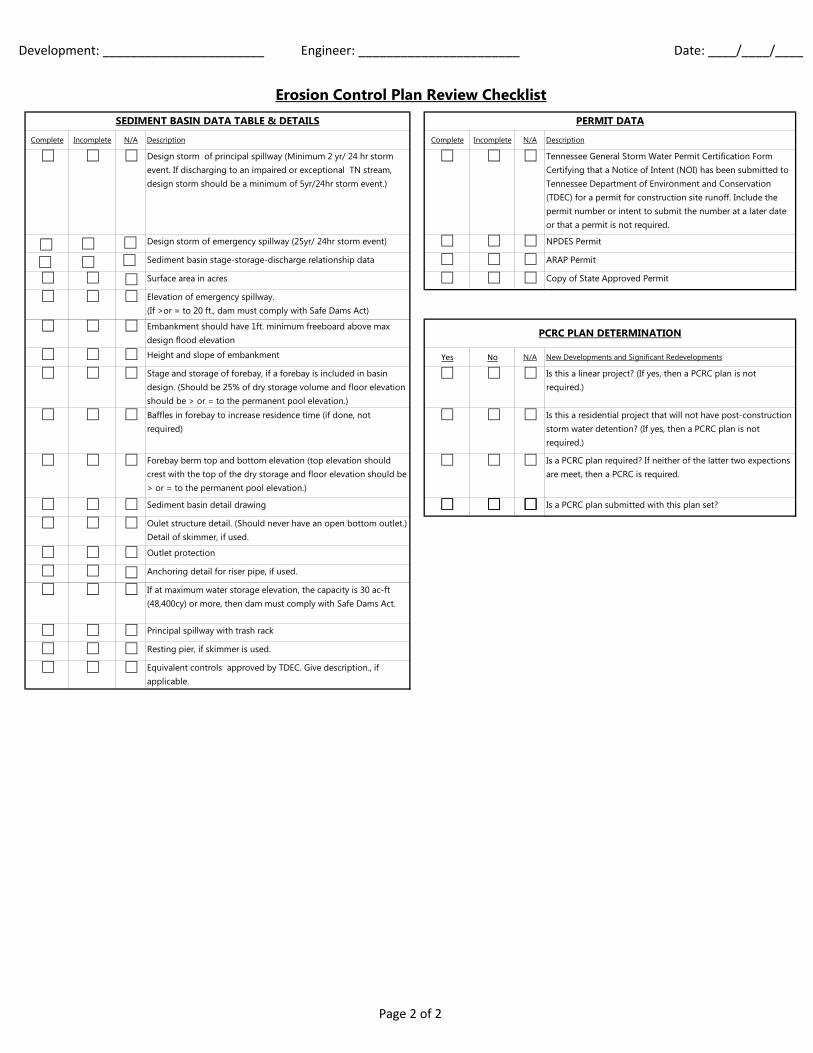
Development: _______________________ Engineer: _______________________ Date: ____/____/____
Complete Incomplete N/A Description Complete Incomplete N/A Description
Design storm of principal spillway (Minimum 2 yr/ 24 hr storm event. If discharging to an impaired or exceptional TN stream, design storm should be a minimum of 5yr/24hr storm event.)
Tennessee General Storm Water Permit Certification Form Certifying that a Notice of Intent (NOI) has been submitted to Tennessee Department of Environment and Conservation (TDEC) for a permit for construction site runoff. Include the permit number or intent to submit the number at a later date or that a permit is not required.
Design storm of emergency spillway (25yr/ 24hr storm event) NPDES Permit
Sediment basin stage-storage-discharge relationship data ARAP Permit
Surface area in acres Copy of State Approved Permit
Elevation of emergency spillway. (If >or = to 20 ft., dam must comply with Safe Dams Act)
Embankment should have 1ft. minimum freeboard above max design flood elevation
Height and slope of embankment Yes No N/A New Developments and Significant Redevelopments
Stage and storage of forebay, if a forebay is included in basin design. (Should be 25% of dry storage volume and floor elevation should be > or = to the permanent pool elevation.)
Is this a linear project? (If yes, then a PCRC plan is not required.)
Baffles in forebay to increase residence time (if done, not required)
Is this a residential project that will not have post-construction storm water detention? (If yes, then a PCRC plan is not required.)
Forebay berm top and bottom elevation (top elevation should crest with the top of the dry storage and floor elevation should be > or = to the permanent pool elevation.)
Is a PCRC plan required? If neither of the latter two expections are meet, then a PCRC is required.
Sediment basin detail drawing Is a PCRC plan submitted with this plan set?
Oulet structure detail. (Should never have an open bottom outlet.) Detail of skimmer, if used.
Outlet protection
Anchoring detail for riser pipe, if used.
If at maximum water storage elevation, the capacity is 30 ac-ft (48,400cy) or more, then dam must comply with Safe Dams Act.
Principal spillway with trash rack
Resting pier, if skimmer is used.
Equivalent controls approved by TDEC. Give description., if applicable.
SEDIMENT BASIN DATA TABLE & DETAILS PERMIT DATA
PCRC PLAN DETERMINATION
Erosion Control Plan Review Checklist
Page 2 of 2

Development: _______________________ Engineer: _______________________ Date: ____/____/____
Complete Incomplete N/A Description Complete Incomplete N/A Description
Standard Title Block Standard City of Memphis Plan Sheet Layout
Standard Sheet Size Sheet Numbers
Project Name w/ Phase or Section Designator North Arrow
Scale Streets Identified By Names
State Reference Number (e.g. 94-SSC-103) Engineering Firm and Developer Information
Drainage Basin Identification Property Lines
State of TN Professional Engineer Stamp and Signature A Scale No Less Than 1" = 100'.
Proper Signature Lines (No County Engineer) Vicinity Map and Parcel Number.
Sheet Number (Usually 1 of 1) Top of bank labeled
Development Location (i.e., Reference to Nearest Street, Intersection, etc.)
Indicate drainage basin, per City of Memphis drainage basin map (that includes Shelby County). If the basin is known for frequent flooding (i.e., Fletcher Creek), or is in a Sensitive Basin, additional requirements may apply.
At least one benchmark located, with the proper elevation indicated (NGVD to be used exclusively).
Vicinity map based on USGS quad map with site location clearly shown and flow path to named water of the state
Complete Incomplete N/A DescriptionGrading and Drainage Plan with arrows showing storm water flow direction across the site and BMP locations
Intended Use (e.g. single family residential, office park, etc.) Buildings and pavement on property.
Parcel ID(s) Storm water management structures on and in the immediate vicinity of the property
Total Site Area (in acres) Schematics of BMPs located on the site, including outlet structure details indicating design storm event
Impervious Area (in square feet) Existing and proposed site contours at an interval no greater than two (2) feet.
Expected Hot Spots (e.g. power washing, trash/food waste dumpster operation, commercial fuel dispensing, and food grease storage/disposal, etc.)
Floodplain and floodway boundaries, stream buffer zones, and the floodplain elevations. (Stream buffers should begin from top of bank.)
Structural BMPs (e.g. detention/retention ponds, swales, water quality units, etc.)
Ridge lines delineating basins. Sub-basin drainage areas.
O&M requirements for structural BMPs (Inspection and maintainance of the system to ensure proper functioning as designed)
Delineation of wetlands or other environmentally sensitive areas
Non-structural BMPs (street sweeping, employee-training, and material/chemical/waste handling practices)
Certify compliance with all required state or federal storm water permits, if applicable.
Entity responsible for BMP implementation (contact name, address, and phone number) If the organization that will be responsible is yet to be organized, list the name, address and phone number of the person or entity with interim responsibility.
Total drainage area entering storm water detention (acres) [this number includes any off-site drainage area that is received]
Where and how the trash, sediment, oil and other vehicle fluids and other pollutants removed from the storm water system will be disposed. This should include any parameters listed in the TDEC 303(d) list for the water bodies into which the development discharges and for which the development could be a reasonable source.
Total onsite drainage area entering a water quality BMP
Basin Name (Wolf, Loosahatchie, Nonconnah, and Mississippi) State if the discharge from the site goes into another detention structure further downstream, if located within a larger development
Sub-basin (as is currently used on Grading & Drainage Plans) Submit an Inspection and Maintenance Agreement if a structural BMP will be on-site (Available in the SWMM Vol. 1 section 7.0 page 172)
Storm Water Information Table
Post Construction Runoff Control Plan Review Cheklist
TITLE BLOCK & GENERAL INFORMATION GENERAL
Page 1 of 1

Development: _______________ Engineer: _________________________ Date: ____/____/____
Complete Incomplete N/A Description Complete Incomplete N/A Description
Standard Title Block Manhole Size (If Not 4' Diameter Manhole)Standard Sheet Size Flowline Elevations w/ Pipe Size & DirectionProject Name w/ Phase or Section Designator Manhole Top ElevationScale Drop Construction Required if Drop > 2'State Reference Number (e.g. 94-SSC-103) Maximum 3 House Connections Into ManholeSewer Basin Identification 0.1' Drop Across Manholes
State of TN Prof. Eng. Stamp and Signature Manhole Rim Elevations
Proper Signature Lines (No County Engineer) 1.0' above 100 Year Flood ElevationSheet Number (Usually 1 of 1) 1.5' Above Grade in Open AreasDevelopment Location (i.e., Reference to Nearest Street, Intersection, etc.)
0.5' Above Grade in Back Yards
Manhole Spacing (8"-21" Pipe=400' Maximum Spacing)
Complete Incomplete N/A Description
BM or TBM Description & ElevationVicinity MapFEMA 100-yr Flood ElevationState Delegation Stamp ("Health Stamp") Complete Incomplete N/A Description
North Arrow Pipe SizeProperty Lines & Interior Lot Lines Pipe LengthStreet Names Slope in PercentAdjoining Development/Property Owner Names Ductile Iron Requirements (Class 50 Minimum)Perm. Easements (All On 1 Lot) with Size, Ties, etc. (15' Typ.) Less Than 1.5' Clearance with DrainageTemp. Construction Easements - Typical Width 20' Less Than 4.0' of CoverExisting Sewer Data for All Tie-In Points Fill GroundPrivate Sewers Clearly Marked Drop ConstructionPrivate Sewer Certificate Ditch CrossingsUpstream Service Provided (Show Qc / Qd / A)Flow Direction Arrows No House Connections in Lines Over 10"Clearance CL Sewer to Face of Curb (5' MIN) Match Pipe Tops in Manholes EXCEPT 8" into 12"+Off-street Sewer Profile Reference Off-street House Connections DimensionedOff-street Sewer Angles No 8" Pipe Flatter than 0.5% SlopeNew Manhole Ties to Existing Manholes SST-16 Cleanout
Typical Line Location 7' north or west of CL Street Cleanout Location Per StandardsUtilities Affecting Installation (Gas/Water Lines, etc.) Detail IncludedRidgelines Not To Be CrossedOffset from Ditches & StreamsRip-Rap Protection for Ditch Crossings Complete Incomplete N/A Description
Min. Floor Elevations for Lots in "Holes" Typical Cross SectionStandard Ingress/Egress Note Calculations ShowingStandard Notes LoadingErosion Control Details & Notes Barrel SizesSpecial Pipe Notes Where Needed CapacityQc / Qd / A Shown At All Downstream Tie-Ins VelocitySewer Extended Upstream with Manhole & StubNo CADD Partial Wording
SIPHON DATA
PIPE DATA
GENERAL
Sanitary Sewer PlanTITLE BLOCK & GENERAL REQUIREMENTS MANHOLES
Sealed Lids & Vent Stacks Required if Rim Cannot Be Constructed 1.0' Above 100-yr Flood Elevation
Page 1 of 1

APPROVED FOR CONSTRUCTION
PRIVATE SEWER CERTIFICATE
Sewer Plan Notes
LOCATION OF EXISTING UNDERGROUND UTILITIES ARE APPROXIMATE AND
ARE NOT NECESSARILY ALL OF SAME. THE CONTRACTOR SHALL BE
RESPONSIBLE FOR CONTACTING THE APPROPRIATE UTILITY COMPANY TO
DETERMINE THE EXACT LOCATION OF ALL UTILITIES AND/OR UNDERGROUND
STRUCTURES PRIOR TO THE INITIATION OF ANY CONSTRUCTION.
CONTRACTOR SHALL ALSO ASSUME FULL RESPONSIBILITY FOR DAMAGE TO
ANY UTILITIES ENCOUNTERED WITHIN CONSTRUCTION PERIMETERS. FOR SITE
LOCATIONS OF EXISTING UTILITIES INVOLVING M.L.G.&W., SOUTH CENTRAL
BELL, AND/OR TEXAS GAS COMPANY, PLEASE CALL 1‐800‐351‐1111. FOR
SEWER SERVICE LOCATIONS, CALL 901‐636‐8025.
CONTRACTOR SHALL ENSURE UNINTERRUPTED SEWER SERVICE ON EXISTING
SEWER AND SERVICE CONNECTIONS BY PROVIDING AMPLE TEMPORARY
WASTEWATER PUMPING AND/OR BYPASSING.
The following two text blocks and typical construction notes
must appear, exactly as written, on any sanitary sewer plans
submitted to the city. Any additional notes added must be
added after the typical construction notes. Typical
construction notes No. 10 & 11 must also be shown on the plat
for a project.
1.
TYPICAL CONSTRUCTION NOTES
2.THE DOCUMENT BEARING THIS STAMP HAS BEEN RECEIVED AND REVIEWED
BY THE CITY OF MEMPHIS DIVISION OF ENGINEERING UNDER AUTHORITY
DELEGATED BY THE TENNESSEE DEPARTMENT OF ENVIRONMENT AND
CONSERVATION DIVISION OF WATER POLLUTION CONTROL. IT IS HEREBY
APPROVED FOR CONSTRUCTION BY THE CITY ENGINEER AS EVIDENCED BY HIS
SIGNATURE IN THE TITLE BLOCK BELOW.3. CONTRACTOR SHALL MAINTAIN ACCESS TO ALL PROPERTIES.
ALL SANITARY SEWER MANHOLES IN REVERSE CROWN STREETS, ALLEYS, OR
DRIVES (PUBLIC OR PRIVATE) SHALL BE PROVIDED WITH GASKETS AND PLUGS
FOR PICK HOLES TO PREVENT DRAINAGE INFLOW INTO SEWER SYSTEM.
11.
6. THE CONTRACTOR SHALL VERIFY EXISTING DATA AND REPORT ANY
SIGNIFICANT DISCREPANCIES TO THE ENGINEER.
THE CITY OF MEMPHIS SHALL HAVE INGRESS/EGRESS RIGHTS TO USE PRIVATE
DRIVES AND YARDS FOR THE PURPOSE OF MAINTAINING ALL PUBLIC SEWER
LINES AND SHALL BEAR NO RESPONSIBILITY FOR THE MAINTENANCE OF SAID
PRIVATE DRIVES AND YARDS.
10.
APPROVAL EXPIRES 1 YEAR FROM APPROVAL DATE BELOW. THIS APPROVAL
SHALL NOT BE CONSTRUED AS CREATING A PRESUMPTION OF CORRECT
OPERATION OR AS WARRANTING BY THE CITY ENGINEER THAT THE
APPROVED FACILITIES WILL REACH THE DESIRED GOALS.
THE ENGINEER WHOSE SEAL AND SIGNATURE APPEAR BELOW HEREBY
ACCEPTS THE RESPONSIBILITY FOR THE DESIGN OF THE PRIVATE SANITARY
SEWER SYSTEM SHOWN HEREON. THE PRIVATE SANITARY SYSTEM DESIGN
FOR SEWERS LESS THAN 8” MUST BE SUBMITTED, APPROVED AND INSPECTED
BY THE PLUMBING INSPECTOR’S OFFICE AT THE MEMPHIS AND SHELBY
COUNTY OFFICE OF CODE ENFORCEMENT. FOR SEWERS 8” AND LARGER, THE
ENGINEER OF RECORD WILL PROVIDE THE MEMPHIS AND SHELBY COUNTY
OFFICE OF CODE ENFORCEMENT A LETTER CERTIFYING THAT ALL PRIVATE
SEWERS 8” AND LARGER HAVE BEEN INSTALLED AND TESTED IN ACCORDANCE
WITH APPLICABLE LOCAL STANDARDS, OR WHERE NO LOCAL STANDARDS
EXIST, THE STANDARDS OF THE STATE OF TENNESSEE. NO PRIVATE SANITARY
SEWER IS TO BE USED EXCEPT FOR TESTING UNTIL THIS SYSTEM HAS BEEN
APPROVED AND/OR THIS CERTIFICATION HAS BEEN ACCEPTED BY CODE
ENFORCEMENT.
NO TREES, SHRUBS, PERMANENT STRUCTURES, OR OTHER UTILITIES (EXCEPT
FOR CROSSINGS) WILL BE ALLOWED WITHIN SANITARY SEWER EASEMENT. NO
OTHER UTILITIES OR SERVICES MAY OCCUPY SANITARY SEWER EASEMENTS IN
PRIVATE DRIVES AND YARDS EXCEPT FOR CROSSINGS.
13. THE CONTRACTOR SHALL PROVIDE ADEQUATE AND EFFECTIVE EROSION
CONTROL AS NECESSARY TO PREVENT ANY SILTATION INTO EXISTING
DRAINAGE SYSTEM AND/OR ADJACENT PROPERTIES.
8.
ALL SANITARY SEWER TO BE CONSTRUCTED AS PER CITY OF MEMPHIS
STANDARD CONSTRUCTION SPECIFICATIONS. SANITARY SEWER SERVICE
CONNECTIONS TO BE INSTALLED AS PER CITY OF MEMPHIS STANDARD SST‐16.
7.
ALL AREAS IN CUT OR FILL WHERE VEGETATION HAS BEEN REMOVED SHALL BE
SEEDED, MULCHED, FERTILIZED, AND/OR SODDED AS REQUIRED TO PREVENT
EROSION.
5.
4. CONTRACTOR SHALL NOTIFY THE CITY OF MEMPHIS CONSTRUCTION
INSPECTION OFFICE AT 636‐2462 A MINIMUM OF 24 HOURS PRIOR TO
BEGINNING ANY CONSTRUCTION.
ALL SANITARY SEWER, INCLUDING SERVICE CONNECTIONS, WHICH HAS LESS
THAN 1.5’ CLEARANCE (OUTSIDE OF PIPES) WITH DRAINAGE OR IN FILLED
AREAS SHALL BE CLASS 50 D.I.P. OR CONCRETE ENCASED, 10’ MINIMUM BOTH
SIDES OF CROSSING. ALL DUCTILE IRON PIPE (D.I.P.) SHALL BE POLYETHYLENE
LINED OR SHALL BE TREATED WITH PROTECTO 401 OR APPROVED
EQUIVALENT.
9.
ALL SEWER MANHOLE LIDS IN OPEN AREAS ARE TO BE CONSTRUCTED 1.5’
ABOVE PROPOSED GRADE. IN BACKYARDS, MANHOLE LIDS ARE TO BE 1.5’
ABOVE INITIAL GRADE, 0.5’ ABOVE FINAL GRADE.
12.
Page 1 of 1

Development: _______________ Engineer: _________________________ Date: ____/____/____
Complete Incomplete N/A Description Complete Incomplete N/A Description
Standard Title Block Scale
Standard Sheet Size North Arrow
Project Name w/ Phase or Section Designator Street Names of All Affected Roadways
Scale Duration of Traffic Control (Days, Weeks, Etc.)
State of TN Professional Engineer Stamp and Signature Design Speed Limit
Proper Signature Lines (No County Engineer) Existing Striping and Lane Dimensions
Sheet Number (Usually 1 of 1) Existing Roadway Edge of Pavement
Development Location (i.e., Reference to Nearest Street, Intersection, etc.)
Images, Codes and Sizes of Traffic Control Signs
Proposed Location of All Traffic Control Signs
Channelization Devices (Drums, Cones, Etc.)
Other Traffic Control (Barricades, Arrow Boards, Temp. Striping, Etc.)
Clearly Identified Work Area (Hatched)
Non-TCP Linework Not on Plans (Contours, Underground Utilities, Owner Info, etc.)
Pedestrian Access & Signage, Etc. - No Mid-Block Crosswalks
Traffic Control Notes (See Attached)
TITLE BLOCK & GENERAL REQUIREMENTS TRAFFIC CONTROL PLAN
Traffic Control
Page 1 of 1

Page 1 of 4
TRAFFIC CONTROL PLAN NOTES For
Land Development Projects Notes regarding Traffic Control should be placed on each page of the Traffic Control Plans. The numbering for the notes to be shown on the plan should remain as depicted below, even if some notes (per the following guidance) are eliminated. For instance, if notes #31 through #33 are not needed on the TCP, the numbering of the remaining notes would skip from #30 to #34. Attached are the standard City of Memphis Traffic Control Plan Notes. Follow the following guidance on which notes should be used. A Temporary Traffic Control Plan (TCP) is needed for all work that will be performed in the City ROW. This includes work performed in the actual roadway and the sidewalk.
1. Typical notes that should be on TCPs are notes # 1 thru 9, 10 (with curb & gutter) OR 11 (without curb & gutter), 12, 21, 25 (with curb & gutter) OR 24 (without curb & gutter), 28, 35, 36 and 41. Other notes may be required based on the scope of the project.
2. On note # 10, if the drums will stay on the street overnight, please change to Type “A”
warning lights.
3. If NO lane/road closure or construction activities will occur at nighttime, please include note # 34. The developer/contractor cannot change to nighttime closures or activities without prior approval of a revised Traffic Control Plan by City Engineering.
4. Notes #31 thru 33 are for flagger design.
5. The minimum lane width allowed for temporary traffic control is 10’. The City may
consider a lane width less than 10’ if the existing lanes are less than 10’.
6. Any time work is going to be performed that would involve the closure of a sidewalk, a pedestrian traffic control plan is required. Provide the traffic control design for pedestrians on the same plan, and include note # 40. Note that the City does not allow temporary mid-block crosswalks.
7. If no sidewalk will be closed, please include note # 39.
8. If any MATA route is within the traffic control area, please include note # 43.
9. The City does not allow half-road closures, i.e., the road is reduced to one-way traffic.

Page 2 of 4
TRAFFIC CONTROL PLAN NOTES: FOR LAND DEVELOPMENT PROJECTS
(REV. 08-17-16)
1. SEE SECTION 6F.03, SIGN PLACEMENT, OF THE STATE OF TENNESSEE MANUAL ON UNIFORM TRAFFIC CONTROL DEVICES (MUTCD) FOR INFORMATION ON PLACEMENT AND MOUNTING OF SIGNS. 2. SIGNS SHOWN ON THIS PLAN ARE TO WARN TRAFFIC ABOUT THE CONSTRUCTION. OTHER TRAFFIC CONTROL DEVICES MAY BE REQUIRED DURING VARIOUS PHASES OF CONSTRUCTION. 3. NOTHING IN THIS PLAN IS INTENDED TO SUPERSEDE OR RELIEVE THE CONTRACTOR OF THE RESPONSIBILITY OF INSTALLING THE APPROPRIATE TRAFFIC CONTROL DEVICES IN ACCORDANCE WITH THE CURRENT STATE OF TENNESSEE "MANUAL ON UNIFORM TRAFFIC CONTROL DEVICES FOR STREETS AND HIGHWAYS. 4. CONTRACTOR SHALL BE REQUIRED TO NOTIFY THE CITY OF MEMPHIS CONSTRUCTION INSPECTION DEPARTMENT (636-2462) AND TRAFFIC ENGINEERING DEPARTMENT (576-6710) A MINIMUM OF 24 HOURS PRIOR TO COMMENCING CONSTRUCTION OR IMPLEMENTING A TRAFFIC CONTROL PLAN. ALL TRAFFIC CONTROL DEVICES MUST BE IN PLACE BEFORE CONSTRUCTION ACTIVITY BEGINS. 5. SIZES OF ALL SIGNS SHALL COMPLY WITH STATE OF TENNESSEE MANUAL ON UNIFORM TRAFFIC CONTROL DEVICES (MUTCD). 6. ALL TRAFFIC CONTROL DEVICES AND THEIR INSTALLATION SHALL MEET THE STANDARD PRESCRIBED IN THE STATE OF TENNESSEE MANUAL ON UNIFORM TRAFFIC CONTROL DEVICES AND SHALL COMPLY WITH THE STATE OF TENNESSEE STANDARD SPECIFICATIONS FOR ROAD AND BRIDGE CONSTRUCTION SECTION 712 TEMPORARY TRAFFIC CONTROL. 7. ACCESS TO ADJACENT PROPERTIES SHALL BE MAINTAINED AT ALL TIMES. 8. SIDE STREET, DRIVEWAY ACCESS, AND SAFE PEDESTRIAN WAYS SHALL BE MAINTAINED AT ALL TIMES. 9. THE CONTRACTOR SHALL NOT BE PERMITTED TO PARK ANY VEHICLES OR CONSTRUCTION EQUIPMENT DURING PERIODS OF INACTIVITY, WITHIN THE RIGHT-OF-WAY OR WITHIN THIRTY (30) FEET OF THE EDGE OF PAVEMENT WHICHEVER IS LESS, WHEN THE LANE IS OPEN TO TRAFFIC, UNLESS PROTECTED BY GUARDRAIL, BRIDGE RAIL, AND/OR BARRIERS INSTALLED FOR OTHER PURPOSES. PRIVATELY OWNED VEHICLES SHALL NOT BE ALLOWED TO BE PARKED WITHIN THE RIGHT-OF-WAY OR WITHIN THIRTY (30) FEET OF AN OPEN TRAFFIC LANE WHICHEVER IS LESS, AT ANY TIME UNLESS PROTECTED AS DESCRIBED ABOVE. 10. CONTRACTOR SHALL USE PLASTIC DRUMS WITH TYPE “C” WARNING LIGHTS TO SEPARATE TRAFFIC FROM THE CONSTRUCTION AREA. 11. DRUMS WITH TYPE “C” WARNING LIGHTS SHALL DELINEATE THE EDGE OF PAVEMENT THROUGH THE ENTIRE CONSTRUCTION AREA. 12. CONTRACTOR SHALL COVER ALL EXISTING SIGNS THAT CONFLICT WITH THE TRAFFIC CONTROL PLAN SIGNS OR DEVICES DURING CONSTRUCTION AND THEY SHALL REMAIN COVERED DURING CONSTRUCTION AND UNTIL SUCH TIME THAT NO CONFLICT EXISTS. 13. CONTRACTOR SHALL INSTALL TEMPORARY NO PARKING SIGNS AS REQUIRED WITHIN THE TRAFFIC CONTROL AREA. 14. TWO-WAY TRAFFIC SHALL BE MAINTAINED ON ______________________ AT ALL TIMES.

Page 3 of 4
15. DURING CONSTRUCTION, A MINIMUM OF ONE __________ FOOT LANE OF TRAFFIC SHALL REMAIN OPEN TO BOTH DIRECTIONS OF TRAFFIC AT ALL TIMES. 16. CONTRACTOR SHALL BE REQUIRED TO MAINTAIN AT LEAST ONE ________________ FOOT LANE OF TRAFFIC FOR EACH DIRECTION ON ________________ AT ALL TIMES AND SHALL MAINTAIN A TEMPORARY CENTER LINE OR CONES THROUGH THE CONSTRUCTION AREA. 17. ONE/TWO __________ FOOT LANES OF TRAFFIC SHALL REMAIN OPEN TO TRAFFIC AT ALL TIMES. 18. WORK WITHIN THE ROADWAY DURING DIFFERENT PHASES OF CONSTRUCTION SHALL NOT BE ACTIVE AT THE SAME TIME. 19. ONLY ONE PHASE OF THE TRAFFIC CONTROL PLAN SHALL BE ACTIVE AT ANY ONE TIME. 20. ONLY ONE CONSTRUCTION SITE ON ______________ SHALL BE ACTIVE AT ANY ONE TIME. 21. ALL TEMPORARY OR PERMANENT TRAVELED SURFACE SHALL BE INSPECTED DAILY BY THE CONTRACTOR (INCLUDING WEEKENDS) AND NECESSARY PATCHING OR RE-FINISHING PERFORMED. 22. MARKINGS SHALL BE MAINTAINED IN LONG-TERM STATIONARY WORK AREAS AND SHALL MATCH AND MEET THE MARKINGS IN PLACE AT BOTH ENDS OF THE WORK AREA. 23. CENTERLINE/LANE LINES SHOULD BE PLACED, REPLACED, OR DELINEATED WHERE APPROPRIATE BEFORE THE ROADWAY IS OPENED TO TRAFFIC. 24. CHANNELIZING DEVICES SHALL BE REMOVED TO THE EDGE OF PAVEMENT AT THE END OF EACH WORK DAY. NO CLOSURE SHALL BE IN EFFECT FROM 4:00 P.M. UNTIL 9:00 A.M. TWO 12 FOOT LANES SHALL BE OPEN DURING THIS PERIOD WITH AT LEAST A 4 INCH THICK COMPACTED GRAVEL SURFACE. 25. WORK WITHIN THE ROADWAY SHALL BE CONDUCTED BETWEEN 9:00 A.M. AND 4:00 P.M. AND THE ROADWAY SHALL BE COMPLETELY OPEN TO TRAFFIC AT ALL OTHER TIMES AND ALL INAPPROPRIATE SIGNS SHALL BE COVERED OR REMOVED. 26. CONTRACTOR SHALL CONTACT ALL APPROPRIATE AGENCIES BEFORE CLOSING ANY ROADWAYS. 27. CONTRACTOR SHALL CONTACT THE DIVISION OF ENGINEERING AT 576-6710 TO ARRANGE FOR THE BAGGING/REMOVAL OF PARKING METERS. 28. CONTRACTOR SHALL CONTACT THE CITY OF MEMPHIS SIGNAL SHOP AT 528-2844 FOR LOCATION OF SIGNAL CONDUIT AND WIRES. 29. THE APPROPRIATE TRAFFIC CONTROL SHALL BE INSTALLED AT THE INCEPTION OF EACH STAGE OF CONSTRUCTION AND SHALL BE PROPERLY MAINTAINED AND/OR OPERATED DURING THE TIME SUCH SPECIAL CONDITIONS EXIST. THEY SHALL REMAIN IN PLACE ONLY AS LONG AS THEY ARE NEEDED AND SHALL BE IMMEDIATELY REMOVED THEREAFTER. 30. OBLITERATED MARKINGS SHALL BE UNIDENTIFIABLE AS PAVEMENT MARKINGS UNDER DAY OR NIGHT, WET OR DRY CONDITIONS. OVERLAYING EXISTING STRIPES WITH BLACK PAINT OR ASPHALT DOES NOT MEET THE REQUIREMENTS OF COVERING, REMOVAL, OR OBLITERATION; HOWEVER, THE USE OF REMOVABLE, NONREFLECTIVE, PREFORMED TAPE IS PERMITTED WHERE MARKINGS NEED TO BE COVERED TEMPORARILY. 31. AT NO TIME SHALL ONE LANE SECTION BE LEFT OPEN UNATTENDED. WHERE TWO FLAGGERS ARE REQUIRED AND IN CIRCUMSTANCES WHERE ONLY ONE LANE OF TRAFFIC IS OPEN AND

Page 4 of 4
THERE IS NO CLEAR LINE OF SIGHT FROM ONE END OF THE CONSTRUCTION AREA TO THE OTHER, THE CONTRACTOR SHALL PROVIDE RADIO COMMUNICATION OR OTHER APPROPRIATE MEANS OF ESTABLISHING CONTROL OF TRAFFIC. 32. ANYTIME FLAGGER IS NOT PRESENT TO CONTROL TRAFFIC, TWO TRAFFIC LANES MUST BE OPEN TO MAINTAIN TWO-WAY TRAFFIC AND ALL INAPPROPRIATE SIGNS SHALL BE COVERED OR REMOVED. 33. ALL FLAGGERS SHALL BE EQUIPPED WITH A STOP/SLOW PADDLE. 34. IF CONSTRUCTION ACTIVITIES REQUIRE OVER-NIGHT CLOSURE OF ANY PORTION OF THE ROADWAY, A REVISED TRAFFIC CONTROL PLAN SHALL BE SUBMITTED TO AND APPROVED BY THE CITY ENGINEER’S OFFICE. 35. EXISTING STRIPING THAT CONFLICTS WITH THE TEMPORARY TRAFFIC CONTROL DEVICES SHALL BE COVERED OR REMOVED DURING CONSTRUCTION. WHEN CONSRUCTION IS COMPLETE THE EXISTING STRIPING SHALL BE RETURNED TO ITS ORIGINAL STATE. 36. ALL TRAFFIC CONTROL SIGNS SHALL MEET THE MINIMUM RETROREFLECTIVITY LEVELS SPECIFIED IN THE CURRENT EDITION OF THE MANUAL ON UNIFORM TRAFFIC CONTROL DEVICES (MUTCD). 37. ALL TEMPORARY STRIPING SHALL BE PREFORMED TAPE. 38. THE CONTRACTOR MUST REIMBURSE THE CITY OF MEMPHIS FOR LOST REVENUE ASSOCIATED WITH PARKING METER SPACES BLOCKED/REMOVED FOR CONSTRUCTION. 39. THE CONTRACTOR IS PROHIBITED FROM CLOSING THE EXISTING SIDEWALK AT ANYTIME DURING THIS PROJECT. IF A SIDEWALK CLOSURE IS NEEDED, A REVISED TRAFFIC CONTROL PLAN SHALL BE SUBMITTED TO AND APPROVED BY THE CITY ENGINEER’S OFFICE. 40. THE DEVELOPER SHALL PROVIDE A TRAFFIC CONTROL PLAN TO THE CITY ENGINEER THAT SHOWS THE PHASING FOR EACH STREET FRONTAGE DURING DEMOLITION OR CONSTRUCTION OF CURB GUTTER AND SIDEWALK. UPON COMPLETION OF SIDEWALK, CURB AND GUTTER IMPROVEMENTS, A MINIMUM 5 FEET WIDE PEDESTRIAN PATHWAY SHALL BE PROVIDED THROUGHOUT THE REMAINDER OF THE PROJECT. 41. ANY CLOSURE OF THE RIGHT OF WAY SHALL BE TIME LIMITED TO THE ACTIVE DEMOLITION OR CONSTRUCTION. CONTINUOUS UNWARRANTED CLOSURE OF THE RIGHT OF WAY SHALL NOT BE ALLOWED FOR THE DURATION OF THE PROJECT. THE DEVELOPER SHALL PROVIDE ON THE TRAFFIC CONTROL PLAN, THE TIME NEEDED PER PHASE TO COMPLETE THAT PORTION OF THE WORK. TIME LIMITS WILL BEGIN ON THE DAY OF CLOSURE AND WILL BE MONITORED BY THE ENGINEERING CONSTRUCTION INSPECTORS (636-2462) ON THE JOB. 42. THE CONTRACTOR WILL MAINTAIN ACCESS FOR CITY OF MEMPHIS SIGNAL CREWS TO PERFORM MAINTENANCE ON THE SIGNAL POLES IN AFFECTED AREA. 43. THE CONTRACTOR SHALL NOTIFY MEMPHIS AREA TRANSIT AUTHORITY (MATA) AT 722-7100 A MINIMUM OF 48 HOURS PRIOR TO IMPLEMENTING A TRAFFIC CONTROL PLAN.

Development: _______________ Engineer: _________________________ Date: ____/____/____
Complete Incomplete N/A Description Complete Incomplete N/A Description
Standard Title BlockExisting and Proposed Striping (Include Lane Widths and Line Types)
Standard Sheet Size Existing and Proposed Signs
Project Name w/ Phase or Section Designator Parking Signs on Adjacent Sections of Street
Scale Size Legend (Include Sign Designations and Size of Signs)
State of TN Professional Engineer Stamp and Signature Regulatory Speed Limit
Proper Signature Lines (No County Engineer) City Traffic Engineer in Signature Block
Sheet Number (Usually 1 of 1)Include Note - "All Striping Shall be Thermoplastic. Follow City of Memphis Standard Pavement Marking."
Development Location (i.e., Reference to Nearest Street, Intersection, etc.)
North Arrow
Scale
Signing and Striping
TITLE BLOCK & GENERAL REQUIREMENTS SIGNING AND STRIPING PLAN
Page 1 of 1

Development: _______________ Engineer: _________________________ Date: ____/____/____
Complete Incomplete N/A Description Complete Incomplete N/A Description
Standard Title Block Scale (1" = 40')
Standard Sheet Size North Arrow
Project Name w/ Phase or Section Designator Street Names
Scale Sign Legend
State of TN Professional Engineer Stamp and Signature Existing & Proposed Signs
Proper Signature Lines (No County Engineer) Solar Flasher Details
Sheet Number (Usually 1 of 1) Flasher Notes
Development Location (i.e., Reference to Nearest Street, Intersection, etc.)
School Zone Flasher Signal
TITLE BLOCK & GENERAL REQUIREMENTS FLASHERS
Page 1 of 1

Development: _______________ Engineer: _________________________ Date: ____/____/____
Complete Incomplete N/A Description Complete Incomplete N/A Description
Standard Title Block Scale
Standard Sheet Size North Arrow
Project Name w/ Phase or Section Designator ROW and Property Lines
Scale Street Names
State of TN Professional Engineer Stamp and Signature Adjoining Development/Property Owner Names
Proper Signature Lines (No County Engineer) Dimension to Property Line from Side Street
Sheet Number (Usually 1 of 1) Standard Notes
Development Location (i.e., Reference to Nearest Street, Intersection, etc.)
Above Ground Utilities and Storm Drainage Inlets
Existing and Proposed Ingress-Egress Easements
Existing and Proposed Pedestrian Easements
Existing and Proposed Traffic Signal Easements
Label Existing ROW and Dedication
Complete Incomplete N/A Description Existing and Proposed Street Improvements
Advance Detection Needed? Existing and Proposed Sidewalks
Detection Zones Labeled from Inside to Outside (i.e., 2-1 for inside EB thru lane; 2-3 for outside EB thru lane)
Existing and Proposed Curb and Gutter
Striping Shown and Dimensioned Existing and Proposed Medians and Median Openings
Crosswalk Type (Traditional or High Vis.) and Width Existing Underground Traffic Signal Conduits & Pull Boxes
Signal Cabinet Location (ROW or Easement) Type of Detection (Video Req'd for New Signals)
Signal Cabinet Base Mounted Left Turn Operation (PT, PM, PTPM?)
Pole Locations (ROW or Easement) Protected Left Turn Phase Justified thru Traffic Analysis?
Signal Heads (No. of Heads, Locations & Dimensions)(2 min. for through movement)
Phasing
Pull Box Locations (1 per corner; req'd for mast arm) Signal Head and Detection ID Figure
ADA Ramps and Accessibility throughout Intersection Signal Head Display Types
Push Button Locations (ADA Accessible) Pedestrian Signal Display Type (12", Countdown)
Signage (Lane Control; Street Name; Ped. Signs, etc.) Phasing Diagram (Match Sequence Chart?)
Sequence Chart (Match Phasing Diagram?)
Push Button Orientation (Match Phasing & Sequence?)
Emergency Vehicle Pre-emption
Transit Pre-emption
Wiring Diagram
Removal Diagram
Plan Details
Attachment Height (For Span Mount Signal)
Conduit Runs to Cabinet (Size, No. of Pipes, etc.)
Pole Diameter & Height (City Standard)
Conduit Stubs in Poles (2 - 3" PVC, Typical)
Mast Arm Length
Will this signal need to be interconnected to the City of Memphis, Traffic Signal System? If so, all Traffic Signal interconnect details must be shown on the plan. A separate traffic signal interconnect plan may be required if this signal is to be connected to an existing signal that is not currently a part of the City of Memphis, Traffic Signal System.
Traffic Signal PlanTITLE BLOCK & GENERAL REQUIREMENTS SIGNAL PLAN - GENERAL
SIGNAL LAYOUT
Page 1 of 1

Development: _______________ Engineer: _________________________ Date: ____/____/____
Complete Incomplete N/A Description Complete Incomplete N/A Description
Standard Plat Title Block with City project number Key Map (Unless 1 or 2 Plats)
Standard Plat Sheet Size (either Letter or Legal size) Adjacent Plat Numbers
Project Name with Phase or Section Designator CIP Number if City Participation
Scale North Arrow
North Arrow Street Names
State Reference Number (e.g. 94-SSC-103) Property Lines & Cross Street Ties
Sheet Number Corresponding to the Plan & Profile of the Proposed Development Plan
Adjoining Development/Property Owner Names with Instrument Numbers (Supply Copies)
Owner's Name, Verified with County Assessor's website. (Assessor Info. and Most Current Deed Included?)
Bearings/Angles & Distances on Easement Centerline/ Perimeter (Be Consistent on all Plats If Possible)
Drainage and/or Sewer District, where applicable Widths of All Existing/Proposed/Temporary Easements & Rights of Way
Proper Signature Lines (No County Engineer) Street Center Line
Plat Number (1 of X) Bearing & Distance or Curve Info. for All Property Boundaries
Sheet Number (1 of X Unless Only 1) Existing and Proposed Right-of-Way widths for all streets shown on the plat
Space in Upper Right Corner for File Stamp Block Line and Curve Tables
Detail Drawings as Needed
Building Faces
House Numbers
Existing Features (Fences, Trees, etc.), esp. within ROW Acquisition and Easement AreasInstrument Number
Ward, Block and Parcel ID
Plat Book and Page No., if applicable
Designate the Following with Unique Hatch:
Right-of-Way Acquisition
Right-of-Way in Use
Public or Private Drainage Easement
Temporary Construction Easement
Sewer Easement
Any Other Type of Easement or Acquisition
Point of Commencement (At Street Intersection) Shown & LabeledPoint of Beginning Shown & Labeled
Legal Descriptions for all Areas (except Temporary Construction Easements)
Closure Reports for All Areas, including Temporary Construction Easements. Closure Report should match Legal Description and Begin at P.O.B.Area of Permanent & Temporary Showing Encumbered Area (If Any) to Nearest Whole Foot
Property Tied to Centerline of Street
One Plat for Each Property; Each Plat may have Multiple Sheets (R.O.W., Drainage Esmt, etc.) as required to provide clarityAll of Parcel on One Sheet
Text Legible; 0.12" Text Height; Not Overlapping
Drainage Easements Match the Grading & Drainage Plan
Detention Area Denoted, with Detention Note
TITLE BLOCK & GENERAL REQUIREMENTS
Easement Plat Checklist GENERAL
Page 1 of 1