Standards for Road Construction Consent ... - Aberdeenshire · PDF fileinfrastructure services...
180
INFRASTRUCTURE SERVICES STANDARDS FOR ROAD CONSTRUCTION CONSENT AND ADOPTION Issue C.01 – 22 th December 2015
Transcript of Standards for Road Construction Consent ... - Aberdeenshire · PDF fileinfrastructure services...
INFRASTRUCTURE SERVICES
STANDARDS FOR ROAD CONSTRUCTION
CONSENT AND ADOPTION
Issue C.01 – 22th December 2015

i
Contents
Contents ................................................................................................................................. i
Drawing Index ..................................................................................................................... ix
Table Index .......................................................................................................................... xi
Part 1 POLICIES AND PROCEDURES ............................................................................ 1
Preamble ............................................................................................................................ 1
1. The need for Consultation .............................................................................................. 2
1.1. Initial Consultation.................................................................................................. 2
1.2. Drainage .................................................................................................................. 2
1.3. Consultation with Other Bodies ............................................................................. 2
1.4. Consultation Certificates......................................................................................... 3
2. Authority required to Construct New Roads ................................................................. 4
2.1. Necessary Consents ................................................................................................ 4
2.2. Planning Consents................................................................................................... 4
2.3. Construction Consent .............................................................................................. 4
2.4. Design Requirements .............................................................................................. 4
2.5. Other Consents ........................................................................................................ 5
2.6. Private Accesses ..................................................................................................... 5
2.7. Provision of Roads .................................................................................................. 5
2.8. Works in an Existing Public Road .......................................................................... 5
3. Policy regarding Adoption and Maintenance ................................................................ 6
3.1. Adoption of Roads .................................................................................................. 6
3.2. Phased Adoption ..................................................................................................... 6
3.3. Adoption of Footpaths ............................................................................................ 6
3.4. Adoption and Maintenance of Parking Areas ........................................................ 7
3.5. Adoption and Maintenance of Road Lighting ........................................................ 7
3.6. Adoption and Maintenance of Traffic Signs .......................................................... 8
3.7. Structures Agreements ............................................................................................ 8
3.8. Road Bonds ............................................................................................................. 8
3.9. Visibility Splays ...................................................................................................... 8
4. Application for Construction Consent ......................................................................... 10
4.1. Place and Date of Application .............................................................................. 10
4.2. Granting of Consent with Conditions ................................................................... 10
4.3. Submission of Plans and Associated Documents ................................................. 10
4.4. Drainage ................................................................................................................ 12
4.5. Pipes and Culverts Under Roads .......................................................................... 12
4.6. Structures .............................................................................................................. 13
4.7. Safety Audit .......................................................................................................... 13
4.8. Responsibility for Design ..................................................................................... 13
4.9. Soil Report ............................................................................................................ 14
4.10. Mineral Report .................................................................................................. 14
4.11. Docqueting of Plans .......................................................................................... 14
4.12. Notification of Owners ...................................................................................... 14
4.13. Owner’s Objections ........................................................................................... 14
4.14. Hearing of Application ...................................................................................... 14
4.15. Construction Period ........................................................................................... 15

ii
4.16. Right of Appeal ................................................................................................. 15
4.17. Amendments to Consent ................................................................................... 15
4.18. Road Lighting .................................................................................................... 15
4.19. Road Bond ......................................................................................................... 15
5. Inspection Procedures during Construction ................................................................. 17
5.1. Notice of Commencement .................................................................................... 17
5.2. Inspection and Testing .......................................................................................... 17
5.3. Certificates of Testing ........................................................................................... 17
5.4. Certificates of Inspection ...................................................................................... 17
5.5. Notice of Operations ............................................................................................. 17
5.6. Inspection at Completion of Works ...................................................................... 18
5.7. Recovery of Expenses ........................................................................................... 18
5.8. Reduction of Bond ................................................................................................ 19
5.9. Health and Safety .................................................................................................. 19
6. Application for Adoption of New Roads and Footpaths ............................................. 20
6.1. Application for Adoption ...................................................................................... 20
6.2. Footpaths ............................................................................................................... 20
6.3. Documents to Accompany Application ............................................................... 20
6.4. Adoption Inspection .............................................................................................. 20
6.5. Addition to List of Public Roads .......................................................................... 20
6.6. Release of Bond .................................................................................................... 21
Part 2 GEOMETRY AND LAYOUT ............................................................................... 22
Preamble ............................................................................................................................. 22
7. Use of Guidelines for Layout Design .......................................................................... 23
7.1. Consultation .......................................................................................................... 23
7.2. Guideline Principles .............................................................................................. 23
7.3. Road Layout .......................................................................................................... 23
7.4. Road Types ........................................................................................................... 23
7.5. Parking and Service Areas .................................................................................... 23
7.6. Additional Design Consideration ......................................................................... 23
7.7. Future Development ............................................................................................. 24
7.8. Infill Development ................................................................................................ 24
7.9. Rural Areas ........................................................................................................... 24
7.10. Safety Audits ..................................................................................................... 24
7.11. Access Statements ............................................................................................. 25
8. The Road Network ....................................................................................................... 26
8.1. Function ................................................................................................................ 26
8.2. Road Hierarchy ..................................................................................................... 26
8.3. Types of Road ....................................................................................................... 26
8.4. Infill Development ................................................................................................ 27
9. Primary and District Distributor Roads ....................................................................... 28
9.1. Function ................................................................................................................ 28
9.2. Layout ................................................................................................................... 28
9.3. Geometry............................................................................................................... 28
9.4. Verges ................................................................................................................... 28
9.5. Footways/Cycletracks ........................................................................................... 28
9.6. Pedestrian Crossing Facilities ............................................................................... 29
9.7. Abnormal Loads ................................................................................................... 29
10. Local Distributor Roads ............................................................................................... 30

iii
10.1. Function… ......................................................................................................... 30
10.2. Layout ................................................................................................................ 30
10.3. Geometry ........................................................................................................... 30
10.4. Verges ................................................................................................................ 30
10.5. Footways/Cycletracks ....................................................................................... 30
10.6. Pedestrian Crossing Facilities ........................................................................... 30
11. Industrial Access Roads ............................................................................................... 32
11.1. Function ............................................................................................................. 32
11.2. Layout ................................................................................................................ 32
11.3. Geometry ........................................................................................................... 32
11.4. Footways/Cycletracks ....................................................................................... 32
11.5. Verges ................................................................................................................ 32
12. Core Roads ................................................................................................................... 33
12.1. Function ............................................................................................................. 33
12.2. Layout ................................................................................................................ 33
12.3. Geometry ........................................................................................................... 33
12.4. Footways ........................................................................................................... 33
12.5. Verges ................................................................................................................ 33
12.6. Bus Route Provision... ....................................................................................... 33
12.7. Parking ............................................................................................................... 34
13. Housing Roads ............................................................................................................. 35
13.1. Function ............................................................................................................. 35
13.2. Layout ................................................................................................................ 35
13.3. Geometry ........................................................................................................... 35
13.4. Parking ............................................................................................................... 35
14. Home Zones ................................................................................................................. 36
14.1. Function ............................................................................................................. 36
14.2. Legal Framework .............................................................................................. 36
14.3. Layout ................................................................................................................ 36
14.4. Gateways ........................................................................................................... 37
14.5. Cross Corner Visibility ...................................................................................... 37
14.6. Statutory Undertakers ........................................................................................ 37
14.7. Future Maintenance. .......................................................................................... 38
15. Design Criteria…. ........................................................................................................ 39
15.1. Design Criteria for Primary and District Distributor Roads (Table). ............... 39
15.2. Design Criteria for Local Distributor Road (Table)… ...................................... 40
15.3. Design Criteria for Industrial Access Road (Table). ........................................ 41
15.4. Design Criteria for Core Road (Table) ............................................................. 42
15.5. Design Criteria for Housing Road (Table). ....................................................... 43
15.6. Design Criteria for Home Zones (Table). ......................................................... 44
16. Forward Visibility. ....................................................................................................... 45
16.1. Standards ........................................................................................................... 45
16.2. Measurement ..................................................................................................... 45
16.3. Driver’s Eye Level. ........................................................................................... 45
16.4. Target Height. .................................................................................................... 45
16.5. Obstructions to Visibility. ................................................................................. 45
16.6. Stopping Sight Distance. ................................................................................... 45
17. Carriageway Widening on Curves. .............................................................................. 47
17.1. Need for Widening. ........................................................................................... 47
17.2. Residential Roads. ............................................................................................. 47
iv
17.3. Method of Widening. ........................................................................................ 47
18. Road Junctions. ............................................................................................................ 48
18.1. Form of Junction. .............................................................................................. 48
18.2. Priority. .............................................................................................................. 48
18.3. Siting. ................................................................................................................. 48
18.4. Staggered Junctions. .......................................................................................... 48
18.5. Geometry. .......................................................................................................... 48
18.6. Spacing. ............................................................................................................. 48
18.7. Major Road Visibility. ....................................................................................... 48
18.8. Minor Road Visibility. ...................................................................................... 49
18.9. Visibility Splay. ................................................................................................. 50
18.10. Cross Corner Visibility. ..................................................................................... 50
18.11. Special Cases. .................................................................................................... 51
18.12. Gradients. ........................................................................................................... 51
18.13. Frontage Access/Parking ................................................................................... 51
18.14. Dropped Kerbs. ................................................................................................. 51
18.15. Unrestricted Major Road. .................................................................................. 51
18.16. Additional Requirements for Home Zones ....................................................... 51
18.17. Junction Markings. ............................................................................................ 52
18.18. Roundabouts. ..................................................................................................... 52
19. Turning Areas. .............................................................................................................. 59
19.1. Turning Provision. ............................................................................................. 59
19.2. Turning Areas. ................................................................................................... 59
19.3. Geometry. .......................................................................................................... 59
19.4. Body Overhang. ................................................................................................ 59
19.5. Parking. .............................................................................................................. 59
19.6. Informal Courtyards. ......................................................................................... 59
20. Traffic Calming ............................................................................................................ 63
20.1. General .............................................................................................................. 63
20.2. Design Considerations....................................................................................... 63
20.3. Environmental Considerations .......................................................................... 63
20.4. Application/Hierarchy ....................................................................................... 64
20.5. Application on Distributor Roads ..................................................................... 64
20.6. Application to Residential Roads. ..................................................................... 64
20.7. Types of Traffic Calming .................................................................................. 64
20.8. Speed Cushion ................................................................................................... 65
20.9. Road Hump ....................................................................................................... 65
20.10. Speed Table ....................................................................................................... 65
20.11. Raised Junction .................................................................................................. 66
20.12. Chicanes ............................................................................................................ 66
20.13. Pinch Points ....................................................................................................... 67
20.14. Pedestrian Refuges/Traffic Islands ................................................................... 67
20.15. Carriageway Narrowings .................................................................................. 67
20.16. Speed Bend ........................................................................................................ 68
20.17. Lateral Shift in Alignment................................................................................. 68
20.18. Overrun Corners ................................................................................................ 68
20.19. Gateway on a Straight ....................................................................................... 69
20.20. Side Road Gateway ........................................................................................... 69
21. Provision for Pedestrians .............................................................................................. 85
21.1. General .............................................................................................................. 85

v
21.2. Crossing Considerations .................................................................................... 85
21.3. At Grade Pedestrian Crossings.......................................................................... 85
21.4. Grade Separated Pedestrian Crossings .............................................................. 86
21.5. Controlled Pedestrian Crossings ....................................................................... 86
21.6. Possible Enhancements to at Grade Pedestrian Crossings ............................... 86
21.7. Routes on Distributor Roads ............................................................................. 86
21.8. Footway Widths ................................................................................................ 86
21.9. Vehicular Footway Crossings ........................................................................... 87
21.10. Gradients............................................................................................................ 87
21.11. Baffle Barriers ................................................................................................... 87
21.12. Ramps and Steps ............................................................................................... 87
21.13. Disabled Access to Buildings ............................................................................ 87
21.14. Obstacles to Pedestrian Routes ......................................................................... 88
22. Provision for Cyclists ................................................................................................... 90
22.1. General .............................................................................................................. 90
22.2. Objectives .......................................................................................................... 90
22.3. Infrastructure Requirements .............................................................................. 90
22.4. Cycle Audit Procedure ...................................................................................... 91
22.5. Definitions ......................................................................................................... 91
22.6. Format ................................................................................................................ 91
22.7. Signing ............................................................................................................... 92
22.8. Surface ............................................................................................................... 92
22.9. Junctions ............................................................................................................ 92
22.10. Parking ............................................................................................................... 92
22.11. Lighting ............................................................................................................. 93
22.12. Traffic Orders .................................................................................................... 93
23. Rural Areas ................................................................................................................... 95
23.1. Introduction ....................................................................................................... 95
23.2. Hierarchy ........................................................................................................... 95
23.3. Road Width........................................................................................................ 95
23.4. Development on Existing Roads ....................................................................... 95
23.5. Passing Places .................................................................................................... 95
23.6. Junction Visibility Splays .................................................................................. 96
24. Making Up and Adoption of Private Roads ................................................................. 98
24.1. Introduction ....................................................................................................... 98
24.2. Additions to the Statutory List of Public Roads ............................................... 98
24.3. Request for Addition to the Statutory List ........................................................ 98
24.4. Section 13 Notice .............................................................................................. 98
24.5. Appeals Against a Section 13 Notice ................................................................ 99
24.6. Maintenance Period ........................................................................................... 99
24.7. Required Standards ........................................................................................... 99
24.8. Required Surface Condition .............................................................................. 99
25. Vehicular Access to Premises and Servicing Arrangements ..................................... 102
25.1. Access to Premises .......................................................................................... 102
25.2. Service Roads .................................................................................................. 102
25.3. Driveways ........................................................................................................ 102
25.4. Service Areas ................................................................................................... 102
25.5. Kerbside Loading ............................................................................................ 103
26. Car Park Provision ..................................................................................................... 108
26.1. Level of Provision and Adoption Criteria ....................................................... 108

vi
26.2. Rehabilitation .................................................................................................. 108
26.3. Location ........................................................................................................... 108
26.4. Residents’ Parking ........................................................................................... 108
26.5. Visitors’ Parking .............................................................................................. 108
26.6. Walking Distances ........................................................................................... 109
26.7. Bay Sizes ......................................................................................................... 109
26.8. Disabled Persons ............................................................................................. 109
26.9. Car Park Layouts ............................................................................................. 109
26.10. Large Car Parks ............................................................................................... 109
26.11. Access .............................................................................................................. 109
26.12. Lay-by Parking ................................................................................................ 110
27. Statutory Undertakers’ Services ................................................................................. 112
27.1. Provision .......................................................................................................... 112
27.2. Routeing .......................................................................................................... 112
27.3. Routeing in Home Zones ................................................................................ 112
27.4. Location ........................................................................................................... 112
27.5. Service Corridors ............................................................................................. 112
27.6. Road Furniture and Lighting ........................................................................... 113
27.7. Maintenance Access ........................................................................................ 113
27.8. Fire Hydrants ................................................................................................... 113
27.9. Carriageway Crossings .................................................................................... 113
27.10. Manholes ......................................................................................................... 113
27.11. Landscaping ..................................................................................................... 113
27.12. Location Plans ................................................................................................. 114
27.13. Existing Services ............................................................................................. 114
27.14. Installation of Services .................................................................................... 114
27.15. Ducting ............................................................................................................ 114
28. Additional Design Considerations ............................................................................. 116
28.1. Headroom ........................................................................................................ 116
28.2. Disabled Persons ............................................................................................. 116
28.3. Bus Services .................................................................................................... 116
28.4. Bus Stops ......................................................................................................... 116
28.5. Road Widths for Bus Routes ........................................................................... 116
28.6. Traffic Management ........................................................................................ 117
28.7. Fire Fighting .................................................................................................... 117
28.8. Refuse Collection ............................................................................................ 117
28.9. Traffic Noise .................................................................................................... 117
28.10. Clearances........................................................................................................ 117
28.11. Safety Fences/Barriers ..................................................................................... 118
28.12. Traffic Signs and Road Markings ................................................................... 119
28.13. Street Name Plates........................................................................................... 119
Part 3 CONSTRUCTION DETAILS ............................................................................. 122
29. Geotechnical Considerations ...................................................................................... 123
29.1. Introduction ..................................................................................................... 123
29.2. Supporting Technical Documentation ............................................................ 123
29.3. California Bearing Ratio (CBR) ..................................................................... 123
30. Pavement Construction .............................................................................................. 124
30.1. Specification .................................................................................................... 124
30.2. Carriageway Construction ............................................................................... 124

vii
30.3. Formation/Sub-Grade ...................................................................................... 124
30.4. Sub-Grade Drainage ........................................................................................ 124
30.5. Camber, Crossfall and Gradients .................................................................... 125
30.6. Recycled Materials .......................................................................................... 125
30.7. Two Stage Construction .................................................................................. 125
30.8. Tie in to Existing Carriageway ....................................................................... 127
30.9. Concrete Block Carriageway Paving .............................................................. 127
30.10. Footway, Footpath and Cycletrack Construction ........................................... 127
30.11. Flexible Construction ...................................................................................... 127
30.12. Concrete Slab Paving ...................................................................................... 127
30.13. Small Element Slab Paving ............................................................................. 128
30.14. Block Paving ................................................................................................... 128
30.15. Insitu Concrete Paving .................................................................................... 128
30.16. Granolithic Concrete Paving ........................................................................... 128
30.17. Granite Slab Paving ......................................................................................... 128
30.18. Kerbs and Edging ............................................................................................ 130
30.19. Minor Accesses ............................................................................................... 130
30.20. Residential Accesses ....................................................................................... 130
30.21. Pedestrian Crossings ....................................................................................... 130
30.22. Emergency Accesses ....................................................................................... 130
31. Road Drainage ............................................................................................................ 136
31.1. Best Management Practices ............................................................................ 136
31.2. Sustainable Urban Drainage Systems ............................................................. 136
31.3. Drainage Impact Assessment .......................................................................... 136
31.4. Appropriate Level of Treatment ..................................................................... 137
31.5. Road Drainage ................................................................................................. 137
31.6. Footpath/Cycletrack Drainage ........................................................................ 137
31.7. Design of Piped Road Drainage ...................................................................... 137
31.8. Gully Spacing .................................................................................................. 137
31.9. Lay-by Drainage .............................................................................................. 138
31.10. Gullies .............................................................................................................. 139
31.11. Connections ..................................................................................................... 139
31.12. Down Pipes...................................................................................................... 140
31.13. Chambers ......................................................................................................... 140
31.14. Pipework .......................................................................................................... 140
31.15. Outfall Connection .......................................................................................... 140
32. Road Lighting ............................................................................................................. 142
32.1. Application for Consent .................................................................................. 142
32.2. Information to be Supplied .............................................................................. 142
32.3. Inspections ....................................................................................................... 142
32.4. Specification .................................................................................................... 142
32.5. Design .............................................................................................................. 142
32.6. Location of Apparatus ..................................................................................... 143
32.7. Decorative Equipment ..................................................................................... 143
32.8. Column Location ............................................................................................. 143
32.9. Road Opening Permit ...................................................................................... 143
32.10. Existing Services ............................................................................................. 143
32.11. Maintenance .................................................................................................... 144
32.12. Electricity Supply ............................................................................................ 144
32.13. Electricity Consumption .................................................................................. 144

viii
32.14. Bond ................................................................................................................ 144
33. Traffic Signs and Road Markings .............................................................................. 145
33.1. Responsibility of the Developer ...................................................................... 145
33.2. Design and Siting of Traffic Signs .................................................................. 145
33.3. Road Markings ................................................................................................ 145
33.4. Street Name Plates........................................................................................... 145
33.5. Alterations to Existing Signage ....................................................................... 146
34. Road Landscaping ...................................................................................................... 147
34.1. Specification .................................................................................................... 147
34.2. Design .............................................................................................................. 147
34.3. Soft Verge ........................................................................................................ 147
34.4. Topsoil ............................................................................................................. 147
34.5. Grass Seed ....................................................................................................... 147
34.6. Hard Verges ..................................................................................................... 147
35. Contact Names and Addresses ................................................................................... 148
36. Bibliography ............................................................................................................... 149
37. Safety Audit Stages .................................................................................................... 150
38. Accessible Design and Access Audits ....................................................................... 154
38.1. Policy Statement .............................................................................................. 154
38.2. Design Standards ............................................................................................. 154
38.3. Departures from Desirable Standards ............................................................. 154
38.4. Access Audits .................................................................................................. 154
38.5. Access Auditor ................................................................................................ 155
38.6. Access Audit Procedure .................................................................................. 155
38.7. Access Audit Brief .......................................................................................... 155
38.8. Audit Report .................................................................................................... 156
38.9. Designer’s Response ....................................................................................... 156
38.10. Dispute Resolution .......................................................................................... 157
38.11. Project Access Statement ................................................................................ 157
38.12. Maintenance and Repair .................................................................................. 157
Appendix A – List of Consultees ..................................................................................... 158
Appendix B – Design and Check Certificates ................................................................. 159
Design Certificate ......................................................................................... 160
Confirmation of Appointment of Designer .................................................. 161
Check Certificate .......................................................................................... 162
Safety Audit - Stage 1/2/3* Road Safety Audit Certificate.......................... 163
Appendix C – Access Audit Sample Brief, Schedule and Report Summary Sheet ........ 164
Access Audit Brief and Schedule ................................................................. 165
Audit Report Summary Sheet ....................................................................... 168

ix
Drawing Index Figure 18.1 General Layout of a Priority Junction 55
Figure 18.2 Dropped Kerbs at Road Junctions 56
Figure 18.3 Typical Home Zone Entry Detail 57
Figure 18.4 Markings for use with Give Way Sign 58
Figure 18.5 Markings for No Give Way Sign 58
Figure 19.1 Industrial Turning Circle and Banjo 60
Figure 19.2 Industrial and Residential Hammerheads 61
Figure 19.3 Industrial and Residential Road Stubs 62
Figure 20.1 Round Topped Road Hump 70
Figure 20.2 Speed Table 71
Figure 20.3 Tapered Edge Speed Table and Road Hump 72
Figure 20.4 Speed Cushion 73
Figure 20.5 Speed Table Typical Construction Details 74
Figure 20.6 Raised Junction 75
Figure 20.7 Chicane Type 1 76
Figure 20.8 Chicane Type 2 77
Figure 20.9 Chicane Type 3 78
Figure 20.10 Pinch Point 79
Figure 20.11 Central Island 80
Figure 20.12 Width Reduction in Carriageway 81
Figure 20.13 Speed Bend 82
Figure 20.14 Lateral Shift in Alignment 83
Figure 20.15 Overrun Corners 84
Figure 21.1 Typical Baffle Barrier Layout 89
Figure 22.1 “Sheffield” Cycle Racks 94
Figure 23.1 Typical Passing Place Detail 97
Figure 25.1 Typical Footpath Construction 104
Figure 25.2 Kerb Details 105
Figure 25.3 Vehicular Footway Crossings 106
Figure 25.4 Dropped Kerb Detail at Designated Pedestrian Crossing Point 107
Figure 26.1 Off-Road Parking Areas 111
Figure 27.1 Location of Service Mains in Footway 115

x
Figure 28.1 Street Name Plate Layout 120
Figure 28.2 Bus Stop Kerb Detail 121
Figure 30.1 Capping and Sub-Base 131
Figure 30.2 Longitudinal Tie in Details 132
Figure 30.3 Carriageway Widening – Tie in Detail 133
Figure 30.4 Buff Tactile Paving 134
Figure 30.5 Typical Carriageway and Footway Construction 135
Figure 31.1 Typical Road Gully 141
xi
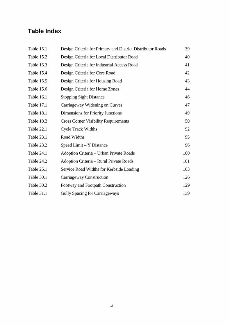
Table Index
Table 15.1 Design Criteria for Primary and District Distributor Roads 39
Table 15.2 Design Criteria for Local Distributor Road 40
Table 15.3 Design Criteria for Industrial Access Road 41
Table 15.4 Design Criteria for Core Road 42
Table 15.5 Design Criteria for Housing Road 43
Table 15.6 Design Criteria for Home Zones 44
Table 16.1 Stopping Sight Distance 46
Table 17.1 Carriageway Widening on Curves 47
Table 18.1 Dimensions for Priority Junctions 49
Table 18.2 Cross Corner Visibility Requirements 50
Table 22.1 Cycle Track Widths 92
Table 23.1 Road Widths 95
Table 23.2 Speed Limit – Y Distance 96
Table 24.1 Adoption Criteria – Urban Private Roads 100
Table 24.2 Adoption Criteria – Rural Private Roads 101
Table 25.1 Service Road Widths for Kerbside Loading 103
Table 30.1 Carriageway Construction 126
Table 30.2 Footway and Footpath Construction 129
Table 31.1 Gully Spacing for Carriageways 139

1
Part 1 POLICIES AND PROCEDURES
Preamble
Part 1 of the guidelines is intended to assist private and public developers in obtaining the
necessary authority, which is required before a new road is constructed and, subsequently,
in having the new road adopted by the Local Roads Authority.
2
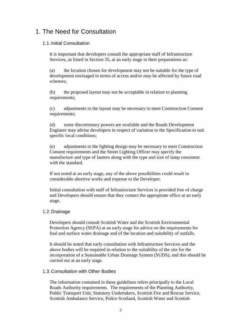
1. The Need for Consultation
1.1. Initial Consultation
It is important that developers consult the appropriate staff of Infrastructure
Services, as listed in Section 35, at an early stage in their preparations as:
(a) the location chosen for development may not be suitable for the type of
development envisaged in terms of access and/or may be affected by future road
schemes;
(b) the proposed layout may not be acceptable in relation to planning
requirements;
(c) adjustments to the layout may be necessary to meet Construction Consent
requirements;
(d) some discretionary powers are available and the Roads Development
Engineer may advise developers in respect of variation to the Specification to suit
specific local conditions;
(e) adjustments to the lighting design may be necessary to meet Construction
Consent requirements and the Street Lighting Officer may specify the
manufacture and type of lantern along with the type and size of lamp consistent
with the standard.
If not noted at an early stage, any of the above possibilities could result in
considerable abortive works and expense to the Developer.
Initial consultation with staff of Infrastructure Services is provided free of charge
and Developers should ensure that they contact the appropriate office at an early
stage.
1.2. Drainage Developers should consult Scottish Water and the Scottish Environmental
Protection Agency (SEPA) at an early stage for advice on the requirements for
foul and surface water drainage and of the location and suitability of outfalls.
It should be noted that early consultation with Infrastructure Services and the
above bodies will be required in relation to the suitability of the site for the
incorporation of a Sustainable Urban Drainage System (SUDS), and this should be
carried out at an early stage.
1.3. Consultation with Other Bodies
The information contained in these guidelines refers principally to the Local
Roads Authority requirements. The requirements of the Planning Authority,
Public Transport Unit, Statutory Undertakers, Scottish Fire and Rescue Service,
Scottish Ambulance Service, Police Scotland, Scottish Water and Scottish

3
Environmental Protection Agency (SEPA) will be extra to these requirements and
should be checked out individually at an early stage.
1.4. Consultation Certificates
The Developer is required to provide the Local Roads Authority with completed
Consultation Certificates before Construction Consent can be granted. Lists of the
required Consultees are included in Appendix A.

4
2. Authority Required to Construct New Roads
2.1. Necessary Consents
Before undertaking any new road construction the Developer must obtain both
Detailed Planning Consent and Construction Consent.
It should be noted that the granting of one does not necessarily imply the
granting of the other.
2.2. Planning Consent
Planning Consent is granted by the Local Planning Authority from whom further
advice should be sought.
2.3. Construction Consent
In terms of Section 21 of the Roads (Scotland) Act 1984, any person or
organisation other than a Roads Authority who wishes to construct a new road or
an extension of an existing road must obtain Construction Consent, irrespective of
whether or not such roads are to be submitted for adoption as public.
Construction Consent is granted by the Local Roads Authority and road
construction works may only be undertaken while the Construction Consent
(Form CC3) remains valid.
Section 151-(1) of the Roads (Scotland) Act 1984 states:
“road” means, (……), any way (other than a waterway) over which there is a
public right of passage (by whatever means) and includes the road’s verge, …….
etc.
2.4. Design Requirements
Construction Consent will be granted only where proposals for the layout and
construction of roads, structures, road drainage and lighting meet the Local Roads
Authority’s standards. Guidance as to how these standards should be achieved is
contained in this document: Geometric and Layout Details in Part 2; Construction
Details in Part 3. Since economy of maintenance will be a major consideration in
the assessment of applications for Construction Consent, the use of structures to
support roads (e.g. retaining walls and bridges) should be avoided wherever
possible. Structures will require the appropriate authorisation including approval
in principle of the structure and the method of analysis.
A key aim of residential street design should be to naturally encourage low traffic
speeds, ideally without having to rely on vertical or horizontal deflection
measures. The design speed for residential streets should normally be a maximum
of 20 mph.

5
2.5. Other Consents
The granting of Construction Consent does not exempt the applicant from
obtaining any other permissions, which may be required such as Planning Consent
or approval for connection to a sewer.
2.6. Private Accesses
A Private Access is defined as any way over which the public does not have a
right of passage. In residential development an access may serve up to five
dwellings.
2.7. Provision of Roads
Six or more individual dwellings should normally be served by a road, which will
require Construction Consent and the submission of a Road Bond in a residential
area.
If the Developer wishes to adopt a layout whereby five or less dwellings will be
served by a Private Access, as there is no public right of access Construction
Consent will not be required and the access will not be eligible for adoption. Such
layouts should provide adequate turning facilities and a satisfactory junction with
a public road. The provision of a Private Access must be indicated clearly at the
planning application stage, otherwise it will be considered that a road is being
provided.
2.8. Works in an Existing Public Road
Any works in an existing public road will require permission from the Roads
Authority under Section 56 of the Roads (Scotland) Act 1984. This is in addition
to the Construction Consent and will always apply where a new road joins into an
existing public road. Application forms should be obtained from the Council’s
office or from the website.

6
3. Policy regarding Adoption and Maintenance
3.1. Adoption of Roads
In terms of Section 16 of the Roads (Scotland) Act 1984, the Local Roads
Authority will, upon request, adopt – i.e. add to its list of public roads and
maintain thereafter – any new road (including any associated footway, cycle track
or verge) constructed in accordance with Construction Consent.
3.2. Phased Adoption
To avoid long delays between construction and adoption of roads, developers are
recommended to programme construction to enable the adoption of roads to be
phased as sections of work are completed, subject to the following conditions: -
(a) Carriageways, footways, cycle tracks, street lighting and verges will not be
adopted separately;
(b) In general only lengths of road between junctions or completed culs-de-sac
will be adopted.
(c) All roads submitted for adoption should form a continuous system with
existing roads.
(d) They should serve a public need.
3.3. Adoption of Footpaths
In terms of Section 18 of the Roads (Scotland) Act 1984, the Local Roads
Authority, will upon request, adopt any footpath which is the subject of such an
Agreement. The suitability of footpaths, for adoption will be judged against the
following criteria:
(a) They should be constructed in accordance with a Construction Consent;
(b) They should form part of a general pedestrian network interconnecting
houses, shops, schools, public transport etc. and must be available for public use
on an unrestricted basis:
(c) Footpaths should either join two public places or serve more than one
individual dwelling.
(d) Where footpaths lead to both front and rear of houses, in general, only one
will be adopted unless they serve another public purpose:
(e) Surfaced areas surrounding buildings, and intended for maintenance
purposes, will not be considered for adoption.
(f) A network of footpaths should abut the public road at least at one point, to
facilitate access for maintenance purposes;
7
(g) Arrangements of steps which prevent access to isolated lengths of footpath
should be avoided if practicable.
3.4. Adoption and Maintenance of Parking Areas
In both new development and redevelopment, the developer will normally be
required to provide parking spaces off the carriageway in accordance with the
current Aberdeenshire Council parking standards. The suitability of such areas for
adoption and maintenance by the Local Roads Authority will be judged against
the following criteria:
(a) Parking area contiguous to the carriageway will normally be adopted as
public roads provided that their use by the general public is not restricted in any
manner and that they are additional to residents’ off-street parking, garages and
drives.
(b) Off-road parking areas, which have been identified as meeting a general
public parking need and have been constructed in accordance with Construction
Consent, may be taken over in certain circumstances. For such an area to be taken
over the Developer must enter into an agreement with the Local Roads Authority
whereby the ground will heritably vest in the Local Authority.
(c) Private parking areas provided in lieu of garages or private drives and
restricted to use by residents will not be taken over for maintenance purposes by
the Local Roads Authority and must therefore be subject to private maintenance
agreements. Accesses to such areas from the prospective public road must be
designed and constructed so as to leave no ambiguity about the boundary of the
publicly maintainable area.
3.5. Adoption and Maintenance of Road Lighting
Lighting installations on publicly maintainable roads and footpaths will be taken
over by the Local Roads Authority for operation and maintenance from the date of
formal adoption for the roads, provided that they have been installed in
accordance with a Construction Consent and to the satisfaction of the Roads
Development Engineer. The Developer shall submit the necessary Test
Certificates to confirm that the electrical installations have been installed in
accordance with national standards prior to adoption.
Until the lighting system is formally adopted the developer will be responsible for
all charges relating to the operation of the lighting installations. The Developer
will be obliged to submit evidence of agreements with an electricity supplier
and a suitable maintenance contractor.
Aberdeenshire Council may be willing to provide these services on a fully
rechargeable basis.

8
3.6. Adoption and Maintenance of Traffic Signs
Traffic signs on publicly maintainable roads and footpaths will be taken over by
the Local Roads Authority from the date of formal adoption for the roads,
provided that they have been installed in accordance with Construction Consent
and to the satisfaction of the Roads Development Engineer.
It should be noted that the regulatory signs, such as Give Way and Stop signs, and
street nameplates should be installed prior to the occupation of the first property
served by a particular road within the development. The temporary installation of
an approved sign will be acceptable at the discretion of the Roads Development
Engineer.
3.7. Structures Agreements
Where Construction Consent provides for a road to be supported by a structure,
the Local Roads Authority will normally enter into an agreement with the
developer, in terms of Section 79(1) (c) of the Roads (Scotland) Act 1984,
whereby the bridge will heritably vest in the Local Roads Authority. Other
essential structures will also require an agreement to enable these structures and
solums to vest in the Local Roads Authority. However, where a bridge or other
structure and solum have not been so acquired, the Local Roads Authority will be
responsible only for maintaining the road surface.
Retaining walls should only be used in exceptional circumstances at the discretion
of the Roads Development Engineer. Walls constructed to support the road (at the
time of road construction) will normally be adopted. Walls constructed to retain
adjacent ground and/or forming part of a building will not be adopted.
3.8. Road Bonds
In terms of the Roads (Scotland) Act 1984 and the Security for Private Road
Works (Scotland) Regulations 1985, (S.I. 2080), as amended by The Security for
Private Road Works (Scotland) Amendment Regulations 1998, (S.I 3220),
developers are required to make financial provision with the Local Roads
Authority in order to safeguard the completion of housing development roads
which are the subject of Construction Consent. Such provision, which may take
the form of a “Road Bond” or deposit, protects prospective house purchasers from
having to bring incomplete roads up to adoptable standards. It should be noted
that no building works can commence until such securities have been lodged.
A security in favour of the Local Roads Authority will also require to be lodged as
part of any agreement whereby substantial works affecting the existing public
road network are being undertaken by private bodies.
3.9. Visibility Splays
In general visibility splays at junctions will form part of the road and thus be
adopted. There must be a permanent and continuous demarcation of the boundary
between the verge and adjoining property (e.g. by a fence, wall or concrete edge

9
kerbing). In most circumstances any footway should be located at the rear of the
splay.
Cross corner visibility splays need not always form part of the road and in these
cases will not be adopted. However they will only be acceptable if they are
subject to a Planning condition restricting the height of any future potential
restriction to visibility i.e. hedges or fences. Additionally, in terms of Section
83(1) (b) an obstruction notice will be served on the developer. The developer
must ensure that the restrictions outlined in the notice are contained within the
title deeds to that plot and must submit a copy of such to the Local Roads
Authority.
10
4. Application for Construction Consent
4.1. Place and Date of Application
An application for Construction Consent should be made on Form CC1,
obtainable at the Infrastructure Services offices listed in Section 35. Completed
application forms should be submitted at least three months prior to the
intended commencement of construction to the Roads Development Engineer
appropriate to the locality of the development.
The application for Construction Consent should demonstrate how the proposed
road layout integrates with both the existing public road network and possible
adjacent future developments. This will require consultation with the Local
Planning Authority.
The Consent area may be phased and the value of the Road Bond will be relative
to each phase. However, each section must be able to provide traffic turning
within the section.
The Developer must indicate the period required for Construction Consent (See
Section 4.15).
It should be noted that the Construction Consent is not transferable. Should
another Developer take over the control and development of the site a new
Construction Consent must be obtained. An agent can act on behalf of a
Developer although the consent will be issued in the name of the Developer. The
Roads Development Engineer must be advised of the Agent at the time of
application and of any subsequent changes.
4.2. Granting of Consent with Conditions
Under the terms of Section 21(3) of the Roads (Scotland) Act 1984 the Local
Roads Authority may “grant construction consent either without conditions or
subject to such conditions as they think fit”. Any such conditions form an integral
part of the Construction Consent and failure to comply with any such conditions is
an offence, which shall be triable either summarily or on indictment.
A condition relating to construction period will be included in every Construction
Consent, in accordance with Section 21(4) of the Roads (Scotland) Act 1984.
(See Section 4.15)
4.3. Submission of Plans and Associated Documents
Applications for Construction Consent should be accompanied by four paper
copies of detailed working drawings folded to A4 size and other associated
documents which should include the following information:-
(a) A location plan, showing proposed development on the Ordnance Survey
base, to a scale of 1:1250 or 1:2500, showing the proposed road network and its
relationship to existing development.
11
(b) A layout plan of the carriageways, footways, cycle tracks, verges,
footpaths, retaining walls, bridges or other structures and earthworks to a scale of
1:500 (1:200 where pedestrian/vehicle/cycle shared surfaces are proposed)
showing:
(i) The proposed centre, building and kerb lines (and also the heel of the
footway where this differs from the building line);
(ii) Curve radii of the road alignment and junctions;
(iii) Dimensioned visibility splays at road junctions;
(iv) Vehicular access points to properties;
(v) Pedestrian crossing points at junctions and other locations where dropped
kerbs will be located;
(vi) Cycle crossing points with dropped kerbs where shared use facilities are
proposed;
(vii) The location of all road gullies including connections to sewer;
(viii) The location of the road drainage system and its discharge points;
(ix) The location and type of lighting columns and lanterns, wall mounted
lighting units (if applicable), control pillars, underground cables and road crossing
ducts;
(x) The location of all underground services and ancillary apparatus;
(xi) The full extents of all cut and fill slopes;
(xii) The boundaries of any areas which it is intended will subsequently be
offered for adoption or maintenance;
(xiii) The layout and specification of all road markings, signs, street name plates
and traffic signals including supports and foundations;
(xiv) Precise site limits;
(xv) Ground floor levels;
(xvi) Details of SUDS system;
(xvii) Driveway gradients;
(xviii) Locations of traffic calming measures;
(xix) Landscaping layout showing locations of all landscaping within the
highway boundary referenced to the landscaping details described in paragraph
4.3 (o).
(c) Road Profiles to a scale 1:500 Horizontal 1:100 Vertical
(d) Surface Water Drainage Profiles to a scale 1:500 Horizontal 1:100
Vertical.
(e) Typical Cross Sections .
(f) Section 79(1) Agreement for any bridges or structures.
(g) A Safety Audit for the design should be included, where appropriate, in
accordance with HD19/03 Safety Audit Certificate(s).
(h) Consultation Certificates from appropriate bodies.
(i) Site Investigation Information.
12
(j) Design and Check Certificates see Appendix B.
(k) General Arrangement Drawing of all Structures showing the structural
form, clear span(s) and other leading dimensions, headroom or clearance,
materials, finishes and parapets with elevation, plan and typical cross sections to
scales 1:50, 1:20, 1:10 as appropriate.
(l) Cycling Audit.
(m) Access Statement for the design in accordance with the procedure in
Section 39 of this document.
(n) Details of landscaping within the highway boundary for the proposed
development.
(i) Layout plan showing proposed landscaping including areas to be
grassed and planting beds.
(ii) Planting schedule for all landscaping areas including seed mixes
for grassed areas, species of plants and plant sizes proposed.
It will be acceptable for these documents to be submitted in an approved
electronic format. The Roads Development Engineer should be contacted to
confirm details of acceptable electronic formats.
4.4. Drainage
Design calculations, including check certificate, for the drainage system will be
required to show the adequacy of both the system and the discharge points.
Drainage layouts and designs must be approved by the Roads Development
Engineer and Scottish Water. Where connection of the road drainage to a public
sewer is not permitted alternative arrangements for road drainage should be
agreed with the Local Roads Authority, Scottish Water and the Scottish
Environmental Protection Agency (SEPA).
Where connections are made to a private drainage system written confirmation is
required to show that authority has been obtained from the appropriate proprietor,
and other relevant agencies, such as SEPA.
A Consultation Certificate will be required indicating that Scottish Water and
SEPA are in agreement with the proposed drainage layout.
4.5. Pipes and Culverts under Roads
For pipes and culverts under roads a hydrological study of the catchment area
along with a hydraulic design of the proposed pipe or culvert and outfall should be
provided along with confirmation that this has been checked independently. Grills
should be designed to facilitate ease of maintenance and prevent flooding and,
13
where possible, grills should allow for overflow during flood conditions or where
the grill face is blocked with debris.
4.6. Structures
Where proposals involve any structure listed in paragraph 3.3 of BD 2/12
“Technical Approval of Highway Structures” (this includes bridges and
culverts with clear span or internal diameter greater than 2.0m, and
corrugated steel buried structures with spans of 0.9m or more) the
Developer must obtain Technical Approval of the structure(s).
The Local Roads Authority will be the Technical Approval Authority for any
structure which is to be adopted. Where a structure is identified as required it is
recommended that the Roads Development Engineer should be contacted at an
early stage to agree the design parameters required. The certificates contained in
Annex C to BD 2/12 must be submitted for all stages including construction.
If the need for additional or amended structures arises after the granting of
Construction Consent, the Developer should seek approval in accordance with BD
2/12 before starting construction.
The standards to be used for design shall be those set out in the DMRB, unless
otherwise agreed by the Technical Approval Authority. Where aspects of the
design are not covered by the requirements of the DMRB, the Developer shall
propose suitable standards as an alternative. The Developer should note in
particular the requirements for aesthetic qualities (BA 41/98) and durability
standards (BD 57/01 & BA 57/01).
As-built records for structures shall be provided as described in BD 62/07 as part
of the application for the adoption of the structure. (See Section 6.3)
4.7. Safety Audit
All roads, junctions, improvements by Developers will require to be audited for
safety. A copy of the Safety Audit should be included with the Construction
Consent application. All Safety Audits shall be carried out by an Aberdeenshire
Council approved Safety Audit Team in accordance with HD19/03. (See Sect 37)
For all schemes a Stage 2 Safety Audit should be carried out and the results
submitted. For certain schemes a Stage 3 Audit will also be required. Further
guidance on this can be sought from the Roads Development Engineer.
Under certain circumstances Aberdeenshire Council would be prepared to offer
this service to Developers for the appropriate fee.
4.8. Responsibility for Design
The granting of Construction Consent does not imply that the Local Roads
Authority accepts any responsibility for the accuracy or suitability of the design.
14
4.9. Soil Report
A soil report should be provided (at the time of application or prior to construction
commencing) giving the C.B.R. test results of the sub-grade, for sub-base
determination.
If the road construction (including carriageway, footway and any other paved
area) is to be less than 450mm the soil report should include a certificate of non-
frost susceptibility for the sub-grade.
The site investigation should also determine the suitability of the underlying soil
for the chosen SUDS treatment methods and this should be considered in the
submitted report.
4.10. Mineral Report
In areas which are known to have been infilled or have a history of mineral
workings the Roads Development Engineer may require the developer seeking
Construction Consent to supply a mineral report together with supporting
information on ground stability.
4.11. Docqueting of Plans
It is essential the plans, detailed drawings and specification submitted with
the application are docqueted, “This is the plan/drawing/specification
referred to in the application”, signed and dated by the applicant.
4.12. Notification of Owners
Where any person other than the developer owns land which fronts, abuts or is
comprehended in the new road(s) or the extension of the existing road(s) for
which Construction Consent is being sought, the developer will be required to
declare on Form CC2 (obtainable at the Infrastructure Services offices or the
Aberdeenshire Council Web Site) that all such persons have been notified of the
application for Construction Consent. Copies of the notices serviced on Owners
must be included.
4.13. Owner’s Objections
Any person to whom the application has been intimated under the provisions of
the preceding paragraph may, within twenty-eight days of the date of intimation,
make written representation to the Local Roads Authority. Any such
representation will be considered before Construction Consent is granted.
4.14. Hearing of Application
Should it be considered that the application for Construction Consent be refused
or granted subject to special conditions, the applicant will be afforded an
opportunity to be heard by the Roads Authority prior to such a decision being
made.
15
4.15. Construction Period
It will be a standard condition of any Construction Consent that the Construction
will be completed within the period specified in the Consent. This period will
not be less than three years and will based on the Developer’s proposed
programme of works.
If, as a result of a change in circumstances during construction, it is demonstrated
that the specified period is no longer realistic, the Local Roads Authority may
grant an extension. It will be a condition of any extension that the design should
be amended if necessary to take account of any changes to the Council’s standards
since the granting of the original consent.
In normal circumstances, once homes are occupied, no more than one
extension of time will be granted by the Local Roads Authority.
If the full development is not completed within the specified period, including any
extension, the Developer will be required to amend the Construction Consent to
allow adoption of that part which is open to public use.
Alternatively, the roads will be completed by the Local Roads Authority using the
Road Bond.
4.16. Right of Appeal
If an application for Construction Consent is (i) refused or (ii) granted subject to
special conditions, the applicant may within twenty-eight days of the date of
intimation of such a decision appeal to the Scottish Ministers.
4.17. Amendments to Consent
Should the developer, for any reason, wish to depart from the construction or
layout details for which Construction Consent has been granted, he must first seek
the approval of the Roads Development Engineer. Major changes may require the
submission of a new application for Construction Consent.
4.18. Road Lighting
The Developer should note that provision of road and footway lighting is made by
the Developer and at his own expense, such provision to be to the specification of
the Local Roads Authority – See Section 32. In the interest of public safety the
Developer shall provide operational street lighting adjacent to occupied housing.
4.19. Road Bond
Where a developer is required to lodge a Road Bond or deposit (Section 3.8) the
Form of Bond (obtainable at the Infrastructure Services offices or the
Aberdeenshire Council Web Site) should be completed and submitted.

16
An A4 size drawing shall be provided showing the Construction Consent area
applied for outlined in red. The area for which a bond is required for any section
within the Consent area is to be outlined in blue.
The Roads Development Engineer shall determine the amount of bond “sufficient
to meet the cost of completing the private road in accordance with the
Construction Consent.”
The Road Bond must be lodged with the Local Roads Authority before any
house building can commence.
17
5. Inspection Procedures during Construction
5.1. Notice of Commencement
Two weeks written notice must be given to the Roads Development Engineer of
the start of roadworks together with names, telephone numbers and email
addresses of responsible persons who may be contacted in connection with the
construction of the works.
5.2. Inspection and Testing
During the construction period, irrespective of whether or not it is intended that
the road(s) be subsequently adopted as public, the Roads Development Engineer
must be afforded access to the site to ensure that the works are being undertaken
in conformity with the Construction Consent. The Developer and/or his
contractor shall provide every facility to enable the Roads Development Engineer
to examine the works being executed and the materials being used, but the
Developer shall remain responsible for ensuring that standards are met.
In certain circumstances the Roads Development Engineer may require samples of
the various materials to be used together with particulars as to the source of supply
or manufacture of such materials to allow further testing to be carried out. These
samples will be provided free of cost by the Developer.
The Developer will also bear the cost of any inspection and testing required by the
Roads Development Engineer.
5.3. Certificates of Testing
The Developer will be responsible for providing test certificates for all
materials used on site. Details of the applicable tests, frequency testing, etc.
are outlined in the Specification, Appendix 1/5.
All testing is to be carried out by a laboratory carrying specific UKAS
accreditation for the required tests.
5.4. Certificates of Inspection
Notwithstanding any use the Developer may make of consulting engineers, and
the submission of certificates of inspection from consulting engineers, the Roads
Development Engineer must be afforded access to the site in all cases to carry out
inspections as deemed necessary by the Roads Development Engineer, and the
Developer will be required to meet the cost of these inspections.
5.5. Notice of Operations
The Developer must give the Roads Development Engineer a minimum of 48
hours written notice (excluding weekends) of the following operations:

18
(a) Commencement of each of the pavement layers to the carriageways,
footways, cycle tracks and footpaths;
(b) Each concrete pour (including blinding) and commencement of steel fixing
where reinforced concrete is used;
(c) Setting out of road lighting plant positions, backfilling of cable trenches
and painting of lighting columns;
(d) Approval of formations;
(e) Approval of foundations;
(f) Installation of bearings;
(g) Steelwork erection;
(h) Bridge deck waterproofing;
(i) Bridge deck expansion joints;
(j) Alignment of stringcourses or parapets.
If the works are suspended for any reason the Developer must comply with the
above requirements prior to restarting on site.
It should be noted that these are minimum requirements and that, in certain cases,
the Developer may be required to notify the Roads Development Engineer of
additional construction stages.
5.6. Inspection at Completion of Works
Towards completion of any development incorporating new roads, a request
should be made to the Roads Development Engineer to have an inspection carried
out. As a result of this inspection, a list of any remedial work required to bring
the road(s) up to the Local Roads Authority standards will be prepared. Following
the satisfactory completion of any such remedial work, an application may be
made as detailed in Section 6.0 for the addition of the road(s) to the Local
Authority’s list of public roads.
It should be noted that where a Stage 3 Safety Audit has been required by the
Roads Development Engineer it must be carried out and the result submitted prior
to the final inspection of the works.
5.7. Recovery of Expenses
Attention is drawn to Section 140(6) of the Roads (Scotland) Act 1984 which
entitles the Local Roads Authority to recover expenses reasonably incurred
by them to ensure that the work carried out complies with the Construction
Consent.
The recovery of these costs will be from the person to whom the Construction
Consent was granted.
The Local Roads Authority gives notice of its intention to recover those
expenses to which it is entitled under the Act.

19
5.8. Reduction of Bond
At pre-determined stages in the construction partial release of the bond, up to a
maximum of 90%, may be permitted.
On completion of the carriageway binder course and kerb log to the satisfaction of
the Roads Development Engineer written application may be made for a reduction
in Bond to 50% of its value.
On completion of the carriageway, footways and cycle tracks to adoptable
standard, a written application may be made for a reduction in Bond to 10% of its
value.
5.9. Health and Safety
The Developer is advised of his responsibility under the Construction (Design and
Management) Regulations 2007 (CDM). The Developer should be satisfied that
he has appointed a competent CDM Co-ordinator, Designer and Principal
Contractor.
The Roads Development Engineer may require details of the appointed CDM Co-
ordinator.
NOTE: New Construction (Design and Management) Regulations 2015
(CDM 2015) will come into force on 6 April 2015. Transitional arrangements
will run for six months from 6 April 2015 to 6 October 2015
20
6. Application for Adoption of New Roads and Footpaths
6.1. Application for Adoption
Following completion of a private road constructed in accordance with a
Construction Consent, a written application for its inclusion in the Local Roads
Authority’s list of public roads may be submitted to the appropriate Roads
Development Engineer by the person to whom such consent was granted.
6.2. Footpaths
Only those footpaths which have been agreed in accordance with paragraph 3.3
will be eligible for adoption.
6.3. Documents to Accompany Application
The submission should include copies of the drawings described in paragraph 4.3
amended as required to show the relevant as-built details , including those
detailed in Section 4.6 for structures, where applicable. These drawings may be
submitted as paper copies or electronic versions in an Adobe .pdf or AutoCAD
.dwg format. The roads, footways, cycle tracks and structures offered for adoption
should be shown in colour, and the plans should clearly indicate the ownership of
all areas so coloured. A 1/2500 scale drawing showing the development should be
included.
If a Stage 3 Safety Audit has been requested the results of this audit shall be
provided along with the application.
In addition the Developer will be required to provide a copy of the site Health and
Safety File. This should include details of construction techniques used and
maintenance requirements for any novel features included in the development,
such as structures, SUD systems and the like. Further guidance can be sought on
this topic from “Managing Health and Safety in Construction. Construction
(Design and Management) Regulations 2007. Approved Code of Practice”,
published by the Health and Safety Executive.
6.4. Adoption Inspection
Within a period of twelve months from the time of application for adoption of a
new road, an inspection will be undertaken by the Roads Development Engineer
to ensure that the road has not deteriorated to a standard below that required for
adoption. Any defects will have to be made good to the satisfaction of the Roads
Development Engineer.
6.5. Addition to List of Public Roads
Following a satisfactory adoption inspection, recommendation will be made to the
Local Roads Authority that the roads be added to the list of public roads, in terms
of the Roads (Scotland) Act 1984, as appropriate.

21
6.6. Release of Bond
Following a satisfactory adoption inspection, which would allow the adoption of
roads to proceed, a written application may be made for the remaining security or
Bond to be returned.

22
Part 2 GEOMETRY AND LAYOUT
Preamble
This part of the document is intended to assist developers in the geometric design of road
layouts and associated facilities. The following sections describe first how the guidelines
should be used to conceive a layout in terms of road hierarchy and then give some
detailed design guidance for each type of road for associated facilities.

23
7. Use of Guidelines for Layout Design
7.1. Consultation
Whenever it is intended to construct a new road or extend existing roads, the
desirability of consultation from the earliest stage cannot be over-emphasised.
7.2. Guideline Principles
An understanding of the principles behind these guidelines is essential in their
application to the geometric design of road layouts and the following paragraphs
are included to brief developers in this respect.
7.3. Road Layout
It is not the intention to dictate road layout to the developer but rather to
indicate how an overall design concept can be realised by different
combinations or various types of road, always taking account of such factors
as road safety, the environment and ease of maintenance.
7.4. Road Types
The type of road required for a particular situation is governed by its function and
by the type and volume of traffic that will use it. Since, for access roads, traffic
volume is directly related to the number and type of premises served, each
element of a road system is defined in terms of the development, which takes
access from it.
7.5. Parking and Service Areas
Vehicles parked on the carriageway may reduce both the safety and traffic
capacity of a road and development design should therefore aim to minimise this
practice. Guidance on achieving this objective is contained in Sections 25 and 26,
but detailed advice regarding appropriate parking and servicing provision for a
particular development should be sought from the Roads Development Engineer.
Off road parking areas in residential areas that are provided in lieu of garages or
private driveways are not acceptable for adoption.
7.6. Additional Design Consideration
A road layout should not be conceived in isolation but as an element in the overall
design of a development. Developers should ascertain at an early stage the
requirements of the Statutory Undertakers, Public Transport Unit and others
concerned with servicing the development and make reference to the design notes
contained in Sections 27 and 28.
The design should be consistent with any planning requirements, particularly if a
development brief exists for the site. A good design should take account of the
following aspects:

24
i) Character of the site and surrounding area;
ii) Existing topography;
iii) Conservation status of the surrounding area;
iv) Planning guidance within the Local Plan and its supplements.
7.7. Future Development
The developer must anticipate future extensions to the development since the
level of access provided may limit the extent to which further development
will be permitted. It should be noted that future development strategies are
indicated in the Aberdeenshire Local Plan. Road types should therefore be
related to the final volumes of traffic envisaged which will not necessarily be
solely those generated by the initial development. A plan indicating possible
future extensions should be prepared and submitted to the Roads
Development Engineer.
7.8. Infill Development
In greenfield development the application of these guidelines is relatively
straightforward, however the redevelopment of existing “built-up” areas and
“infill” development is less so. While the basic principles outlined above are
equally applicable to these latter sites, the constraints of adjacent developments
and the prevailing conditions in the locality may give rise to complications in
achieving the desired standards. It is therefore of paramount importance that the
Roads Development Engineer is consulted at the earliest opportunity where infill
development is contemplated, so that any difficulties in complying with these
guidelines can be identified and alternative proposals evaluated. Cognisance
should also be taken of the likelihood of further redevelopment or subsequent road
improvements.
7.9. Rural Areas
It should be noted that these guidelines refer essentially to urban areas. In rural
areas, where higher vehicle speeds necessitate more stringent design criteria,
reference should be made to the Design Manual for Roads and Bridges. Further
guidance on rural development standards is given in Section 23.
7.10. Safety Audits
Safety Audits will be required for all developments, except where express
exemption has been granted by the Roads Development Engineer. For all
schemes a Stage 2 Safety Audit should be carried out and the results submitted.
For certain schemes a Stage 3 Audit will also be required. Further guidance on
this can be sought from the Roads Development Engineer. (See Section 37).
The Safety Audits must be carried out in accordance with HD19/03, by an audit
team approved by Aberdeenshire Council. The cost of such audits will be borne
by the Developer.

25
7.11. Access Statements
Access Statements will be required for all developments, except where express
exemption has been granted by the Roads Development Engineer. Further
guidance on this can be sought from the Roads Development Engineer. (See
Section 38).

26
8. The Road Network
8.1. Function
The Road network fulfils a complex variety of functions in linking and forming
places where people can live, work and move around. Whilst providing for
movement along a street is vital, it should not be considered independently of the
street’s other functions and good street design demands that issues of place and
movement are considered together. (See Designing Streets)
8.2. Road Hierarchy
A stepped approach to road characteristics has been defined in the form of a roads
hierarchy as set out in paragraph 8.3. Other combinations of hierarchy may be
permissible for small gap sites at the discretion of the Local Roads Authority.
All new roads will be designed and constructed in accordance with this hierarchy
with consideration being given to the classification of existing roads. This
hierarchy establishes the principle of access, designated design speed and the
spacing and nature of junctions.
8.3. Types of Road
In considering road infrastructure for new developments it is first necessary to
define each element of the road network (both existing and proposed) according to
its principal function.
(a) PRIMARY DISTRIBUTOR ROADS – provide for traffic movements into
and out of a town and link major residential and commercial districts. The design
of this category of road will normally be the responsibility of the Local Roads
Authority;
(b) DISTRICT DISTRIBUTOR ROADS – provide for major traffic
movements within a town or district. The design of this category of road will
normally be the responsibility of the Local Roads Authority;
(c) LOCAL DISTRIBUTOR ROADS – distribute traffic within a district and
link District Distributor Roads to Residential Roads;
(d) INDUSTRIAL ACCESS ROADS – link industrial/commercial premises
and their associated parking areas to Local Distributor Roads.
(e) RESIDENTIAL ROADS – provide frontage access to properties within a
residential area and link with Local Distributor Roads. They have been further
categorised as follows:
(1) CORE ROADS – link residential premises and associated parking
areas to Local Distributor Roads;

27
(2) HOUSING ROADS - link residential premises and associated parking
areas to Local Distributor Roads either directly or via Core Roads;
All residential roads should have a design speed no greater than 20 mph.
(f) HOME ZONES – provide an alternative approach to providing access to
residential properties
8.4. Infill Development
In established built up areas, where redevelopment of a gap site is proposed, it
may not be possible to provide the hierarchy set out in paragraph 8.3, especially
where roads, which on account of their traffic volume should be classed as
Distributors, already feature frontage access to dwellings. Guidance on individual
cases should be sought from the Roads Development Engineer.

28
9. Primary and District Distributor Roads
9.1. Function
PRIMARY and DISTRICT DISTRIBUTOR ROADS comprise a network of
roads that provide for traffic movements linking major industrial and residential
areas and also provide for traffic movements into and out of a town. DISTRICT
DISTRIBUTOR ROADS are the feeder roads for LOCAL DISTRIBUTOR
ROADS which connect into the lower ends of the hierarchy.
9.2. Layout
The layout of PRIMARY and DISTRICT DISTRIBUTOR ROADS should be
designed to encourage the through movement of general traffic.
9.3. Geometry
The standard width of carriageway shall be 7.3m and bus bays will be required at
bus stops. The Roads Development Engineer may require the inclusion of
pedestrian refuges adjacent to bus bays. The design speed adopted will depend on
the intended speed limit of the proposed road, but is likely to be at least 60kph.
Consultation with the Roads Development Engineer will be required to determine
the intended speed limit for the proposed road.
When the speed limit for the proposed road has been set, Table 2 of TD 9/93
(DMRB 6.1.1) should be used to determine the appropriate design speed for the
proposed road.
In circumstance where the proposed road is not considered to be an Urban Road
then the design speed shall be determined in accordance with Chapter 1 of TD
9/93 (DMRB 6.1.1).
9.4. Verges
A verge at least 2 metres wide shall be provided at all times on each side of the
carriageway unless otherwise directed by the Roads Development Engineer.
9.5. Footways/ Cycletracks
The aim both in new development and in redevelopment should be to achieve a
system whereby pedestrians and cyclists are segregated from vehicle movements.
In most instances footways/cycletracks should be provided remotely from the
PRIMARY or DISTRICT DISTRIBUTOR ROAD. Where footways/cycletracks
do run alongside PRIMARY or DISTRICT DISTRIBUTORS they shall be at least
3 metres wide and shall be separated from the carriageway by a 2.0 metre verge.
It should be noted that combined footways/cycletracks will require to be the
subject of a formal Traffic Order and signed in accordance the current version of
The Traffic Signs Regulations and General Directions. The Developer will be
liable for the costs associated with the required Traffic Order and route signage.

29
9.6. Pedestrian Crossing Facilities
Normally where pedestrian movements are likely to be high and the relevant
criteria can be met, facilities for pedestrians will be provided by means of
controlled or grade separated crossings. However, in certain circumstances it may
be more appropriate to reduce vehicle speeds to allow pedestrians to cross more
safely. Details of appropriate traffic calming features are highlighted in Section
20.
9.7. Abnormal Loads
The design of PRIMARY and DISTRICT DISTRIBUTOR ROADS must take
account of the requirements for the movement of abnormal loads. Certain routes
within Aberdeenshire Council are used to move abnormally large vehicles, and
these routes have specific features to ensure that this can be done as easily as
possible. Early consultation with the Roads Development Engineer should be
undertaken to determine if the proposed route is likely to be used for the
movement of Abnormal Loads. If this is the case further guidance will be given
as to specific features that shall be included in the overall design. This may
include aspects such as demountable street furniture or additional clearance
requirements to obstructions.

30
10. Local Distributor Roads
10.1. Function
LOCAL DISTIRBUTOR ROADS distribute traffic within environmental areas
and form the link between DISTRICT DISTRIBUTORS and RESIDENTIAL
ROADS. LOCAL DISTRIBUTORS are traffic routes and not suitable for
frontage development with direct access. They are also likely to be potential bus
routes. Any road serving more than three hundred dwellings or serving both
residential and industrial developments must be designed to at least LOCAL
DISTRIBUTOR standards.
10.2. Layout
The layout of LOCAL DISTRIBUTOR ROADS should be designed to discourage
major through movement of general traffic.
10.3. Geometry
The standard width of carriageway shall be 6.5 metres Roads giving access to
industrial development shall be at least 7.3 metres wide. The Roads Development
Engineer may require the inclusion of bus bays and adjacent pedestrian refuges. .
A design speed of at least 60kph shall be adopted for determining road alignment
in accordance with the national Design Manual for Roads and Bridges.
10.4. Verges
A verge at least 2 metres wide shall be provided at all times on each side of the
carriageway unless otherwise directed by the Roads Development Engineer.
10.5. Footways/ Cycletracks
The aim both in new development and in redevelopment should be to achieve a
system whereby pedestrians and cyclists are segregated from vehicle movements.
In most instances footways/cycletracks should be provided remotely from the
LOCAL DISTRIBUTOR ROAD. Where footways/cycletracks do run alongside
LOCAL DISTRIBUTORS they shall be at least 3 metres wide and shall be
separated from the carriageway by a 2.0 metre verge.
It should be noted that combined footways/cycletracks will require being the
subject of a formal Traffic Order and signed in accordance the current version of
The Traffic Signs Regulations and General Directions. The Developer will be
liable for the costs associated with the required Traffic Order and route signage.
10.6. Pedestrian Crossing Facilities
Normally where pedestrian movements are likely to be high and the relevant
criteria can be met, facilities for pedestrians will be provided by means of
controlled or grade separated crossings. However, in certain circumstances it may
be more appropriate to reduce vehicle speeds to allow pedestrians to cross more

31
safely. Details of appropriate traffic calming features are highlighted in Section
20.

32
11. Industrial Access Roads
11.1. Function
INDUSTRIAL ACCESS ROADS provide frontage or service access to industrial
and commercial premises.
11.2. Layout
INDUSTRIAL ACCESS ROADS should preferably form a loop although a short
cul-de-sac incorporating a turning circle or other approved turning facility
(Section 19) may be considered.
11.3. Geometry
INDUSTRIAL ACCESS ROADS are transitional in nature between full standard
distributor roads and the local industrial/commercial environment and may
therefore be constructed to reduced standards of alignment compared with
Distributor Roads. This will largely depend upon the length of the roads and it is
still desirable to use a formal design speed for assessing curve radii and visibility.
11.4. Footways/ Cycletrack
A shared footway/cycletrack at least 3 metres wide (2.5m in limited situations)
shall be provided on each side of the carriageway (Section 22). However, if
development is to one side of the road only, the requirement for a
footway/cycletrack on the opposite side of the road may be relaxed.
It should be noted that combined footways/cycletracks will require being the
subject of a formal Traffic Order and signed in accordance the current version of
The Traffic Signs Regulations and General Directions. The Developer will be
liable for the costs associated with the required Traffic Order and route signage.
11.5. Verges
Wherever a footway/cycletrack is not provided adjacent to the carriageway, a 2
metres wide grass verge will be required between edge of carriageway and any
fence, boundary wall, hedge, etc.

33
12. Core Roads
12.1. Function
A CORE ROAD may function as a collector road linking a LOCAL
DISTRIBUTOR ROAD to a number of HOUSING ROADS and/or HOME
ZONES. It may act as a housing road in its own right with frontage access to
dwellings. No more than three hundred dwellings in total may be served by a
CORE ROAD.
Where a CORE ROAD is not a loop and serves more than 50 but less than 100
dwellings, an emergency access route must be provided.
Where a CORE ROAD serves in excess of 100 houses it MUST have at least
TWO points of access.
12.2. Layout
CORE ROADS should be laid out to discourage through traffic movements and be
of loop form where possible. Where a cul-de-sac greater than 110m long is
permitted it should incorporate a turning circle.
12.3. Geometry
CORE ROADS are transitional in nature between full standard Distributor Roads
and the local domestic environment and may therefore be constructed to reduced
standards of alignment compared with Distributor Roads. This will largely
depend upon the length of the roads, and it is still desirable to use a formal design
speed for assessing curve radii and visibility.
12.4. Footways
A footway of at least 2.0 metres wide (Section 15) shall be provided on each side
of the carriageway. However, if development is to one side of the road only, the
requirement for a footway on the opposite side of the road may be relaxed. Only
where there is a segregated footpath system, and it can be demonstrated that
pedestrians are unlikely to walk along the access road, may the requirements for
any footway be waived.
12.5. Verges
A 2 metre wide verge will be required whenever a footway is not provided.
12.6. Bus Route Provision
To ensure that the development can be serviced effectively by Public Transport
certain CORE ROADS will require to be designed to a higher standard, to allow
them to serve as Bus Routes. At the design stage the requirements of the Public
Transport Operators may not have been determined.

34
To allow for future implementation of a Public Transport regime, carriageways to
Bus Route standard must be provided to ensure that no dwelling is more than 400
metres, by the shortest designated pedestrian route, from a potential Bus Route.
Further guidance on this matter may be sought from the Roads Development
Engineer.
12.7. Parking
The overall layout of a CORE ROAD should be such as to discourage parking on
footways. This practice is illegal and presents particular hazards to pedestrians,
especially those in the most vulnerable groups.
35
13. Housing Roads
13.1. Function
HOUSING ROADS give access to dwellings and therefore provide the links
between these dwellings and LOCAL DISTRIBUTOR ROADS either directly or
via CORE ROADS.
13.2. Layout
HOUSING ROADS can be laid out in any form, taking access from the CORE
ROAD and from each other as either loops, links or culs-de-sac. Their layout
should be convenient and accessible for the driver without creating long lengths,
or areas which can only be reached by a long and torturous route.
HOUSING ROADS can serve up to 50 properties.
13.3. Geometry
At this level of the road hierarchy formal design speeds are inappropriate but, in
the interest of the local residential environment, vehicle speeds should be
restricted by the use of appropriate geometry and/or traffic calming features to
ensure that the 20mph speed limit zone is self-enforcing.
13.4. Parking
The overall layout of a HOUSING ROAD should be such as to discourage
parking on footways. This practice is illegal and presents particular hazards to
pedestrians, especially those in the most vulnerable groups.

36
14. Home Zones
14.1. Function
HOME ZONES are residential streets in which the road space is shared between
drivers of motor vehicles and other road users, with the wider needs of residents
(including people who walk and cycle, and children) in mind. The aim is to
change the way that streets are used and to improve the quality of life in
residential streets by making them places for people, not just for traffic. Changes
to the layout of the street should emphasise this change of use, so that motorists
perceive that they should give informal priority to other road users.
A normal HOME ZONE will include a combination of the following features:
a) A shared surface
b) Indirect traffic routes
c) Areas of planting
d) User friendly street furniture, i.e. seats or play equipment
e) Entrance/Exit Gateways
f) Appropriate signage and lighting.
The key aim to be achieved by the creation of a HOME ZONE is to turn a
residential street into a valued space, not just a place for movement.
It should be noted that a HOME ZONE is NOT suitable for through traffic. The
design of a HOME ZONE should actively discourage through traffic.
14.2. Legal Framework
The Local Roads Authority may designate any road for which they are traffic
authority as a HOME ZONE under powers granted in the Transport (Scotland)
Act 2001 and The Home Zones (Scotland) (No 2) Regulations 2002.
The Developer will be required to pay the costs of the legal processes involved in
establishing a HOME ZONE.
At the start and end of any HOME ZONE signing in accordance with the current
version of the Traffic Signs Regulations and General Directions will be required.
14.3. Layout
HOME ZONES should be integrated within the wider area, so that they are
permeable and accessible to pedestrians, cyclists and local traffic. There should
be a continuous network of routes for pedestrians and cyclists linking the HOME
ZONE area with schools, public transport stops, green spaces and other services.
In general terms HOME ZONES should be set out to ensure that vehicles should
not have to travel more than 400 metres along a HOME ZONE street. This
distance should be measured from any point within the HOME ZONE to the
nearest conventional street.

37
Ideally a pedestrian should not have to walk more than 400 metres, about 5 minute
walk, to reach the nearest bus stop. The provision of bus services will be outwith
the control of the Developer and the Roads Development Engineer should be
contacted at an early stage to discuss this particular requirement.
The number of houses served by a HOME ZONE should be around 20. However
more properties could be served by sub dividing the area into a number of zones
linked to each other by conventional housing roads.
A HOME ZONE can take the form of streets, squares, courtyards or culs-de-sac.
It is the buildings, trees, planting and surface treatments that should define the
HOME ZONE’S spaces, rather than conventional kerb edges and carriageway
widths. No minimum width is specified for use by vehicles. The overall design
of the HOME ZONE should be checked using a swept path analysis to determine
the width required for vehicles to negotiate the layout. Careful consideration must
be given to access by Emergency and Service vehicles, although the overall
design concept must not be compromised. The use of removable obstructions
may be one option to accommodate these types of access requirements.
Each HOME ZONE should be unique, depending on the building heights,
setbacks, its overall architectural character and the community’s use of the street.
It is unlikely that all this can be achieved within an overall width of less than 8
metres. Designs must incorporate sufficient space for vehicles, pedestrians,
cyclists, services, and leisure activities to coexist.
Further guidance can be sought from the Institute of Highway Incorporated
Engineers document “Home Zones – Design Guidelines” June 2002, and the
Scottish Executive document “Home Zone Guidance Consultation” 2002
14.4. Gateways
It is important that vehicle drivers are aware that they are entering the HOME
ZONE area. This can be achieved by the construction of a gateway feature at the
entrance to the HOME ZONE . Further reference should be made to the Traffic
Calming section of this guide.
14.5. Cross Corner Visibility
The minimum cross corner visibility for drivers joining a HOME ZONE should be
appropriate to the radius of the kerbline (see paragraph 18.10).
14.6. Statutory Undertakers
Within new built HOME ZONES, there is the opportunity to plan the location of
utilities so as they do not conflict with other elements of the HOME ZONE
environment. Close liaison with the Utility companies will be required throughout
the design and implementation stages. Further advice can be found in RAUCS
Advice Note 10 “Guidelines on Positioning Utilities Apparatus in Home Zones.”

38
14.7. Future Maintenance
The Developer will be required to demonstrate that the whole life cost of the
proposal, particularly in relation to bespoke items, has been fully considered in the
design process.
At the design stage close liaison with Landscape Services and the Roads
Development Engineer will be required to ensure that potential problems with
long term maintenance are avoided.

39
15. Design Criteria
Table 15.1 – Design Criteria for Primary and District Distributor Roads
Feature Standard Comment
Design Speed DMRB Consultation with the Roads
Development Engineer will be
required to set speed limit.
Carriageway Width 7.3m See Section 17 for widening on
curves.
Minimum Camber/Crossfall
2.5%
Maximum Gradient DMRB
Minimum Gradient 0.8% Minimum practical from drainage
channels.
Minimum Vertical Curve
Length
DMRB
Minimum Horizontal Curve
Radius
DMRB
Minimum Sight Distance
DMRB
Verges 2m grass
Footways/Cycletrack 3m footway/cycletrack Required on both sides.
May be relaxed to one side in
certain circumstances.
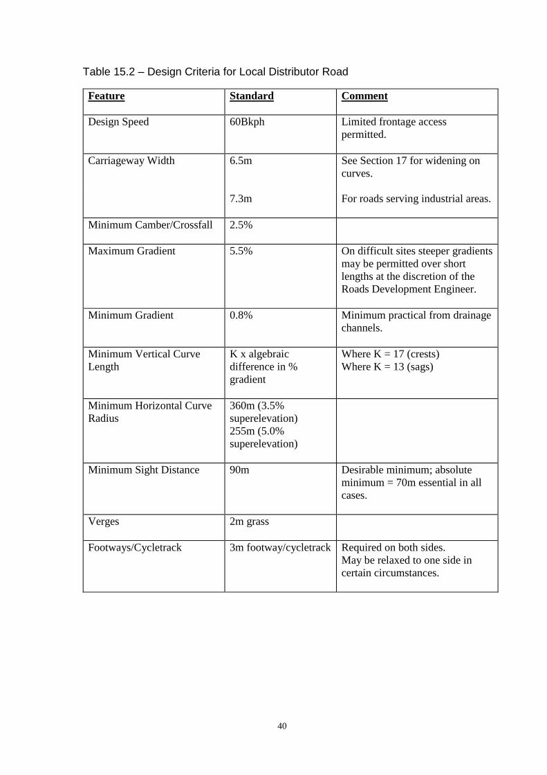
40
Table 15.2 – Design Criteria for Local Distributor Road
Feature Standard Comment
Design Speed 60Bkph Limited frontage access
permitted.
Carriageway Width 6.5m See Section 17 for widening on
curves.
7.3m For roads serving industrial areas.
Minimum Camber/Crossfall
2.5%
Maximum Gradient 5.5% On difficult sites steeper gradients
may be permitted over short
lengths at the discretion of the
Roads Development Engineer.
Minimum Gradient 0.8% Minimum practical from drainage
channels.
Minimum Vertical Curve
Length
K x algebraic
difference in %
gradient
Where K = 17 (crests)
Where K = 13 (sags)
Minimum Horizontal Curve
Radius
360m (3.5%
superelevation)
255m (5.0%
superelevation)
Minimum Sight Distance 90m Desirable minimum; absolute
minimum = 70m essential in all
cases.
Verges 2m grass
Footways/Cycletrack 3m footway/cycletrack Required on both sides.
May be relaxed to one side in
certain circumstances.

41
Table 15.3 – Design Criteria for Industrial Access Road
Feature Standard Comment
Design Speed 50kph Designer to demonstrate
that design is appropriate
for design speed
Carriageway Width 7.3m See Section 17 for widening on
curves.
Minimum Camber/Crossfall 2.5% Adverse camber to be removed.
Maximum Gradient 5.5% May be increased over short
lengths at the discretion of the
Roads Development Engineer.
Minimum Gradient 0.8%
1.25%
Minimum practical from drainage
channels.
Where precast concrete block
paving is to be used.
Minimum Vertical Curve
Length
K x algebraic
difference in %
gradient
Where K = 6 (Crest)
K= 9 (sag);
absolute minimum length = 20m.
Minimum Horizontal Curve
Radius
255m (3.5%
superelevation)
180m (5%
superelevation)
Minimum Sight Distance See 16.6
Verges 2m grass Essential where there are no
footways.
Footways/Cycletracks 3m footway/cycle
track
Required on both sides. May be
relaxed to one side in certain
circumstances.

42
Table 15.4 – Design Criteria for Core Road
Feature Standard Comment
Design Speed 30kph Design must include features to
ensure that 20mph speed limit
would be self-enforcing.
Carriageway Width 5.5m
6.0m
Bus routes.
Minimum Camber/Crossfall 2.5%
Maximum Gradient 5.5% May be increased over short
lengths at the discretion of the
Roads Development Engineer.
Minimum Gradient 0.8% Minimum practical from drainage
channels.
Minimum Vertical Curve
Length
K x algebraic
difference in %
gradient
Where K = 6; absolute minimum
length = 20m.
Minimum Horizontal Curve
Radius
20m Except for speed control bends.
Superelevation not essential.
Minimum Sight Distance See 16.6
Max spacing of traffic
calming events
100m To comply with 20mph Zones
regulations.
Verges 2m grass Essential where there are no
footways.
Footways 2m footway Required on both sides of the
road.
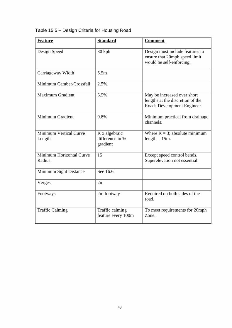
43
Table 15.5 – Design Criteria for Housing Road
Feature Standard Comment
Design Speed 30 kph Design must include features to
ensure that 20mph speed limit
would be self-enforcing.
Carriageway Width 5.5m
Minimum Camber/Crossfall 2.5%
Maximum Gradient 5.5% May be increased over short
lengths at the discretion of the
Roads Development Engineer.
Minimum Gradient 0.8% Minimum practical from drainage
channels.
Minimum Vertical Curve
Length
K x algebraic
difference in %
gradient
Where K = 3; absolute minimum
length = 15m.
Minimum Horizontal Curve
Radius
15 Except speed control bends.
Superelevation not essential.
Minimum Sight Distance See 16.6
Verges 2m
Footways 2m footway Required on both sides of the
road.
Traffic Calming Traffic calming
feature every 100m
To meet requirements for 20mph
Zone.
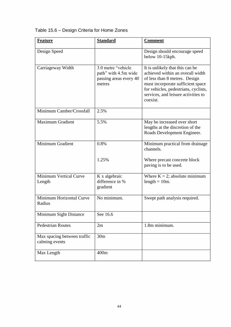
44
Table 15.6 – Design Criteria for Home Zones
Feature Standard Comment
Design Speed Design should encourage speed
below 10-15kph.
Carriageway Width 3.0 metre “vehicle
path” with 4.5m wide
passing areas every 40
metres
It is unlikely that this can be
achieved within an overall width
of less than 8 metres. Design
must incorporate sufficient space
for vehicles, pedestrians, cyclists,
services, and leisure activities to
coexist.
Minimum Camber/Crossfall 2.5%
Maximum Gradient 5.5% May be increased over short
lengths at the discretion of the
Roads Development Engineer.
Minimum Gradient 0.8%
1.25%
Minimum practical from drainage
channels.
Where precast concrete block
paving is to be used.
Minimum Vertical Curve
Length
K x algebraic
difference in %
gradient
Where K = 2; absolute minimum
length = 10m.
Minimum Horizontal Curve
Radius
No minimum. Swept path analysis required.
Minimum Sight Distance See 16.6
Pedestrian Routes 2m 1.8m minimum.
Max spacing between traffic
calming events
30m
Max Length 400m

45
16. Forward Visibility
16.1. Standards
The requirements for forward visibility for each type of road classification are set
out in Sections 14 and 15.
16.2. Measurement
To enable drivers to see a potential hazard in time to slow down or stop
comfortably it is necessary to consider the driver’s line of vision, in both the
horizontal and vertical planes, and the stopping distance of the vehicle.
16.3. Driver’s Eye Level
The eye level of a driver can vary from 1.05m above the carriageway in a standard
car to approximately 2.0m in commercial vehicles. To enable drivers to see each
other across summits, across bends and at junctions, unobstructed visibility will be
required at least between these heights above the carriageway.
16.4. Target Height
For drivers to see and be seen by pedestrians, particularly children and wheelchair
users, unobstructed visibility will be required to a point closer to the ground. As
there is a high likelihood of children in residential areas this lower limit should be
set at 260mm.
16.5. Obstructions to Visibility
The most obvious obstructions to visibility are summits, adjacent buildings, walls,
street furniture, dense trees, and parked cars. It is important that any planting
regime is determined taking account of the impact of future growth on visibility.
Generally the aim should be to ensure good visibility without the need for future
maintenance.
16.6. Stopping Sight Distance
The horizontal distance over which unobstructed visibility should be maintained
will depend on the stopping distance of a vehicle. The stopping site distance of
buses and HGV’s should also be assessed separately where these vehicles
comprise more than 5% of the total traffic flow. The basic formula for calculating
SSD in metres is:
SSD = vt + v2/2(d+0.1a) + b
Where:
v = speed (m/s)
t = driver perception-reaction time (seconds)
d = deceleration (m/s2)
a = longitudinal gradient (%) (+ for upgrades and – for downgrades)
b = adjustment for bonnet length (metres)

46
For design speeds of up to 60kph, the following values shall be used:
t = 1.5 seconds
d(light vehicles) = 4.41 m/s2
d(HGV/bus) = 3.68 m/s2
b = 2.4 metres
Table 16.1 below gives stopping distances for various speeds:
Table 16.1 – Stopping Sight Distances
Design Speed (Kph)
20 25 30 35 40 45 50 55 60 Longitudinal
gradient
SSD(light vehicles) (metres)
15 19 23 28 33 39 46 52 59
0.0%
15 20 24 30 35 42 49 56 64 -5.5%
SSD(HGV/bus) (metres)
15 20 25 30 36 43 50 57 66 0.0%
16 21 26 33 39 47 55 63 72 -5.5%
For design speeds over 60kph, TD 9/93 shall be used
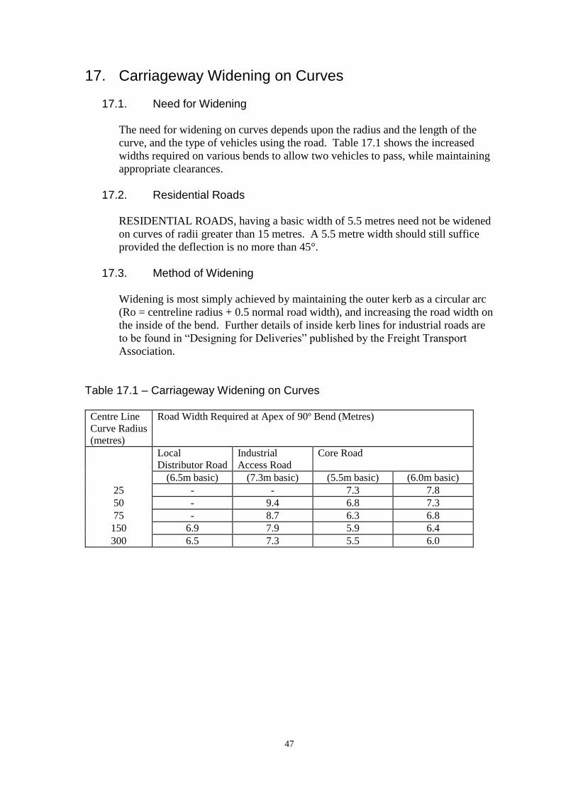
47
17. Carriageway Widening on Curves
17.1. Need for Widening
The need for widening on curves depends upon the radius and the length of the
curve, and the type of vehicles using the road. Table 17.1 shows the increased
widths required on various bends to allow two vehicles to pass, while maintaining
appropriate clearances.
17.2. Residential Roads
RESIDENTIAL ROADS, having a basic width of 5.5 metres need not be widened
on curves of radii greater than 15 metres. A 5.5 metre width should still suffice
provided the deflection is no more than 45°.
17.3. Method of Widening
Widening is most simply achieved by maintaining the outer kerb as a circular arc
(Ro = centreline radius + 0.5 normal road width), and increasing the road width on
the inside of the bend. Further details of inside kerb lines for industrial roads are
to be found in “Designing for Deliveries” published by the Freight Transport
Association.
Table 17.1 – Carriageway Widening on Curves
Centre Line
Curve Radius
(metres)
Road Width Required at Apex of 90o Bend (Metres)
Local
Distributor Road
Industrial
Access Road
Core Road
(6.5m basic) (7.3m basic) (5.5m basic) (6.0m basic)
25 - - 7.3 7.8
50 - 9.4 6.8 7.3
75 - 8.7 6.3 6.8
150 6.9 7.9 5.9 6.4
300 6.5 7.3 5.5 6.0

48
18. Road Junctions
18.1. Form of Junction
In residential areas, junctions should be designed to suit context and urban form –
standardised forms should not dictate the street pattern. In rural areas, where two
roads intersect a right angled T-junction shall be formed with the major road,
defined as that carrying the greater volume of traffic, continuous through the
junction (Fig. 18.1).
18.2. Priority
In general the geometric layout shall clearly establish the priority of the major
road to approaching drivers. The Roads Development Engineer may additionally
require road signs and/or road markings to be provided, at the Developer’s
expense, to emphasise this priority.
18.3. Sitting
It is preferable to site junctions on level ground or in sags rather than at, or near
crests of hills. Where possible T-junctions on curves should be sited so that the
minor road is on the outside of the curve. Junctions on the inside of sharp curves
are most undesirable.
18.4. Staggered Junctions
Where two minor roads approach a major road from opposite sides, a staggered
junction comprising two T’s shall be used instead of a crossroads in rural areas.
Right/Left staggers (where the minor road traffic crossing the major road first
turns right out of the minor road, proceeds along the major road and then turns
left) are preferred to left/right staggers.
18.5. Geometry
Road junctions should be designed to meet the criteria listed in Table 18.1 and, in
residential areas, the principles given in Designing Streets.
18.6. Spacing
Junction spacing (Table 18.1) is related to the likely volumes and speeds of traffic
and to the distance required by moving vehicles to take up position between
junctions for particular movements. The need to maintain road safety and
minimise the likelihood of congestion will dictate the spacing and location of
major access points.
18.7. Major Road Visibility
Drivers approaching a major/minor priority junction along the major road shall be
able to see the minor road entry from a distance corresponding to the Desirable
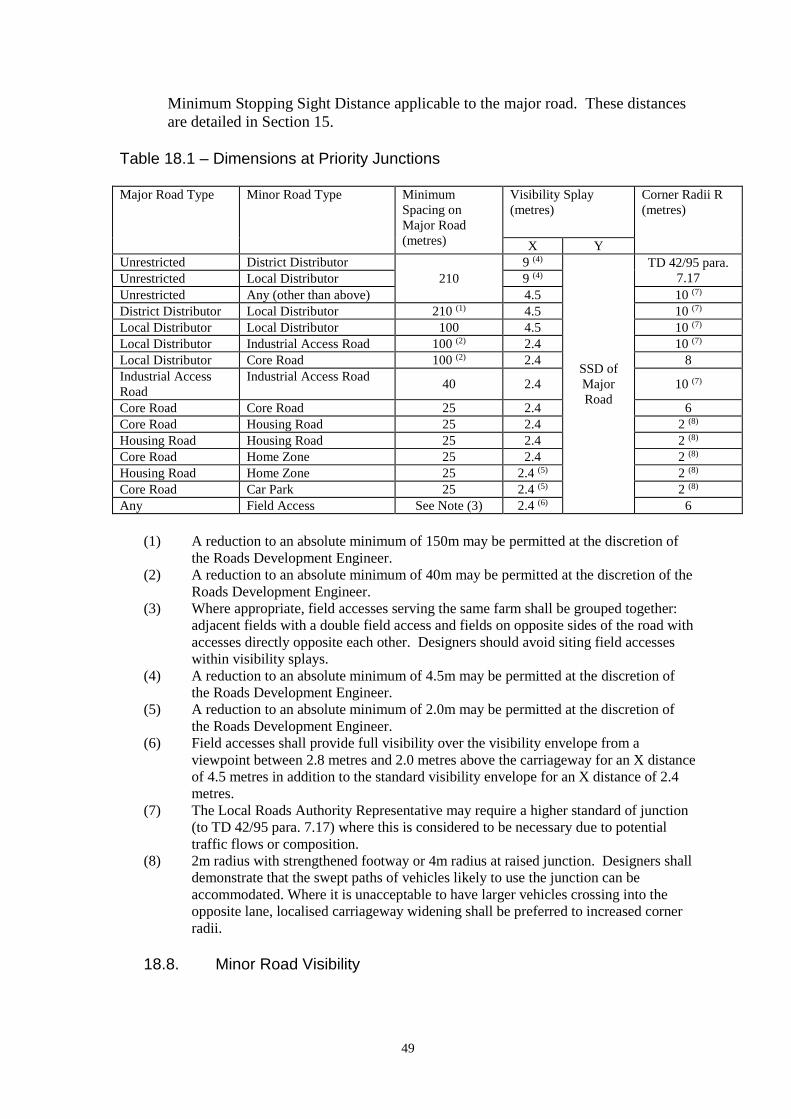
49
Minimum Stopping Sight Distance applicable to the major road. These distances
are detailed in Section 15.
Table 18.1 – Dimensions at Priority Junctions Major Road Type Minor Road Type Minimum
Spacing on
Major Road
(metres)
Visibility Splay
(metres)
Corner Radii R
(metres)
X Y
Unrestricted District Distributor
210
9 (4)
SSD of
Major
Road
TD 42/95 para.
7.17 Unrestricted Local Distributor 9 (4)
Unrestricted Any (other than above) 4.5 10 (7)
District Distributor Local Distributor 210 (1) 4.5 10 (7)
Local Distributor Local Distributor 100 4.5 10 (7)
Local Distributor Industrial Access Road 100 (2) 2.4 10 (7)
Local Distributor Core Road 100 (2) 2.4 8
Industrial Access
Road
Industrial Access Road 40 2.4 10 (7)
Core Road Core Road 25 2.4 6
Core Road Housing Road 25 2.4 2 (8)
Housing Road Housing Road 25 2.4 2 (8)
Core Road Home Zone 25 2.4 2 (8)
Housing Road Home Zone 25 2.4 (5) 2 (8)
Core Road Car Park 25 2.4 (5) 2 (8)
Any Field Access See Note (3) 2.4 (6) 6
(1) A reduction to an absolute minimum of 150m may be permitted at the discretion of
the Roads Development Engineer.
(2) A reduction to an absolute minimum of 40m may be permitted at the discretion of the
Roads Development Engineer.
(3) Where appropriate, field accesses serving the same farm shall be grouped together:
adjacent fields with a double field access and fields on opposite sides of the road with
accesses directly opposite each other. Designers should avoid siting field accesses
within visibility splays.
(4) A reduction to an absolute minimum of 4.5m may be permitted at the discretion of
the Roads Development Engineer.
(5) A reduction to an absolute minimum of 2.0m may be permitted at the discretion of
the Roads Development Engineer.
(6) Field accesses shall provide full visibility over the visibility envelope from a
viewpoint between 2.8 metres and 2.0 metres above the carriageway for an X distance
of 4.5 metres in addition to the standard visibility envelope for an X distance of 2.4
metres.
(7) The Local Roads Authority Representative may require a higher standard of junction
(to TD 42/95 para. 7.17) where this is considered to be necessary due to potential
traffic flows or composition.
(8) 2m radius with strengthened footway or 4m radius at raised junction. Designers shall
demonstrate that the swept paths of vehicles likely to use the junction can be
accommodated. Where it is unacceptable to have larger vehicles crossing into the
opposite lane, localised carriageway widening shall be preferred to increased corner
radii.
18.8. Minor Road Visibility
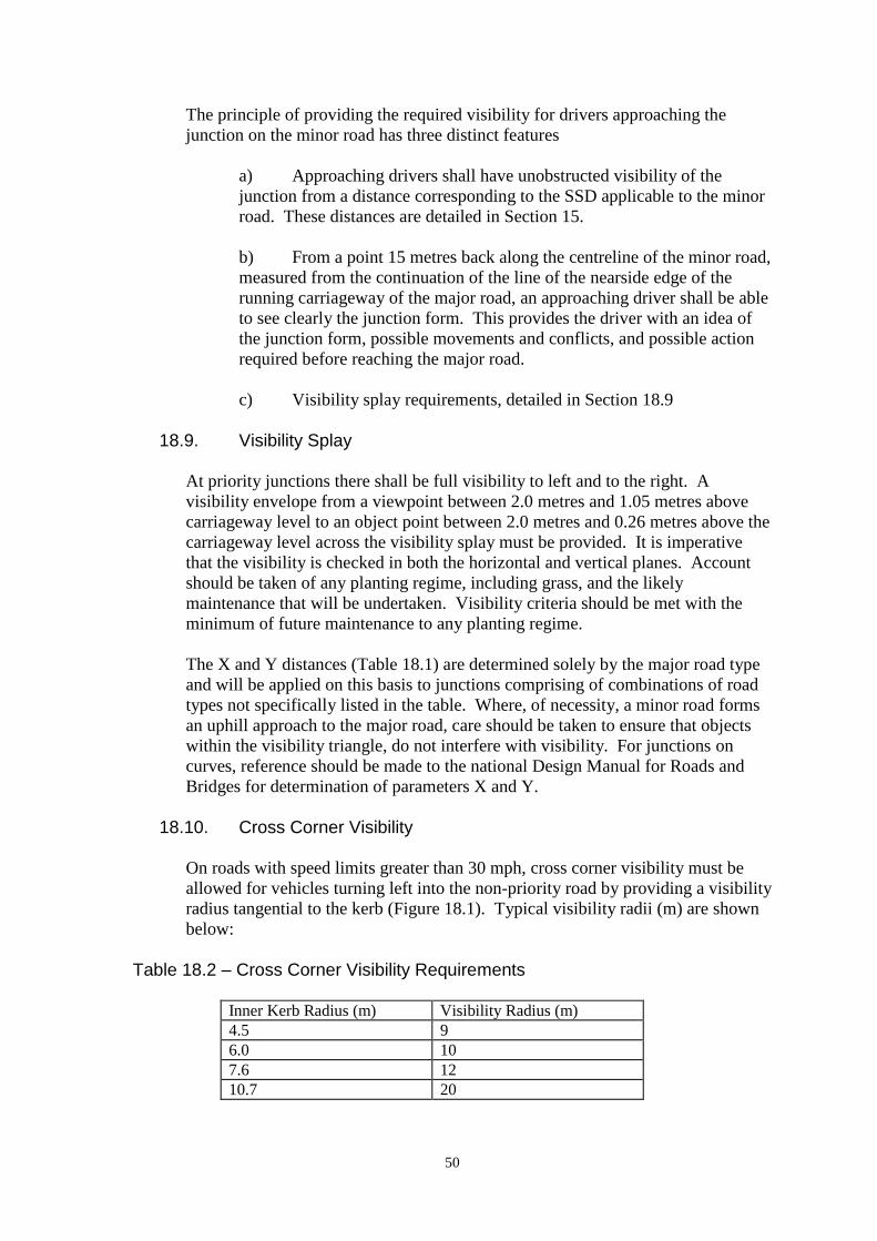
50
The principle of providing the required visibility for drivers approaching the
junction on the minor road has three distinct features
a) Approaching drivers shall have unobstructed visibility of the
junction from a distance corresponding to the SSD applicable to the minor
road. These distances are detailed in Section 15.
b) From a point 15 metres back along the centreline of the minor road,
measured from the continuation of the line of the nearside edge of the
running carriageway of the major road, an approaching driver shall be able
to see clearly the junction form. This provides the driver with an idea of
the junction form, possible movements and conflicts, and possible action
required before reaching the major road.
c) Visibility splay requirements, detailed in Section 18.9
18.9. Visibility Splay
At priority junctions there shall be full visibility to left and to the right. A
visibility envelope from a viewpoint between 2.0 metres and 1.05 metres above
carriageway level to an object point between 2.0 metres and 0.26 metres above the
carriageway level across the visibility splay must be provided. It is imperative
that the visibility is checked in both the horizontal and vertical planes. Account
should be taken of any planting regime, including grass, and the likely
maintenance that will be undertaken. Visibility criteria should be met with the
minimum of future maintenance to any planting regime.
The X and Y distances (Table 18.1) are determined solely by the major road type
and will be applied on this basis to junctions comprising of combinations of road
types not specifically listed in the table. Where, of necessity, a minor road forms
an uphill approach to the major road, care should be taken to ensure that objects
within the visibility triangle, do not interfere with visibility. For junctions on
curves, reference should be made to the national Design Manual for Roads and
Bridges for determination of parameters X and Y.
18.10. Cross Corner Visibility
On roads with speed limits greater than 30 mph, cross corner visibility must be
allowed for vehicles turning left into the non-priority road by providing a visibility
radius tangential to the kerb (Figure 18.1). Typical visibility radii (m) are shown
below:
Table 18.2 – Cross Corner Visibility Requirements
Inner Kerb Radius (m) Visibility Radius (m)
4.5 9
6.0 10
7.6 12
10.7 20
51
18.11. Special Cases
In special cases (e.g. one-way roads) some reduction in the design speed may be
permitted by express permission of the Roads Development Engineer. This may
require the Developer to provide evidence of lower than assumed 85% speeds.
Reductions in design speed will reduce the requirements for the junction.
18.12. Gradients
The maximum gradient of the final approach of the minor road at junctions should
be limited over the X distance to 2 percent where the major road is a DISTRICT
or LOCAL DISTRIBUTOR. In other circumstances the gradient should be
limited to 4 percent over a minimum distance of 8 metres.
18.13. Frontage Access/Parking
No frontage access or lay-by parking will normally be permitted in the immediate
vicinity of a road junction, or where parked vehicles would interfere with junction
sightlines.
18.14. Dropped Kerbs
Provision should be made at all road junctions for pedestrians to continue along
the major road with a minimum of inconvenience. Kerbs must therefore be
dropped as indicated in Figure 18.2, at all junctions. It should be noted that if the
main road is classified as a Distributor Road, or higher, tactile paving MUST be
installed at these dropped kerbs in accordance with the Department for
Transport’s Guidance on the Use of Tactile Paving Surfaces.
18.15. Unrestricted Major Road
Where any minor road connects to a road, proposed or existing, that has an
unrestricted speed limit the design of the junction will comply in every respect
with the standards set out in the current version of the Design Manual for Roads
and Bridges.
18.16. Additional Requirements for Home Zones
HOME ZONES must be clearly marked at their entrances and exits to ensure that
all street users recognise the different nature of the area. The HOME ZONE sign
should be used to provide a clear statement to drivers of the change in operation of
the streets. The use of this sign must be supported by the legal designation of the
area as a HOME ZONE under the appropriate legislation; and the completion of
the necessary physical measures.
In addition to signage a visual statement should be created at the entrance to a
HOME ZONE. At the simplest this “gateway” may just be a change of surface
material or colour, but in most cases more substantial features will be required.
One option would be to create the junction in the form of a footway crossing,

52
thereby giving priority to pedestrians, another option would be to create a raised
junction, see Figure 18.3.
Care should be taken to ensure that the visually impaired are aware of the change
in nature of the road. This can be achieved by the use of tactile paving, possibly
the corduroy pattern. Further details on the use of this material can be found in
Department for Transport’s Guidance on the Use of Tactile Paving Surfaces.
Further guidance on all these aspects can be sought from the Institute of Highway
Incorporated Engineer’s Home Zones – Design Guidelines, The Scottish
Executive’s Home Zones – Guidance Consultation, and the Roads Development
Engineer.
18.17. Junction Markings
Where any road joins a Distributor, or higher, classified road junction marking
and signage shown on Figure 18.4 will be required.
If the junction is with a CORE ROAD, the junction markings shown in Figure
18.5 will be required. In certain circumstances this requirement may be relaxed at
the discretion of the Roads Development Engineer.
In general no junction markings will be required when both roads are Housing
Roads classification or less.
Further guidance on road markings can be found in Section 28 of this guide.
18.18. Roundabouts
Normal or Compact Roundabouts complying with the requirements of TD 16/07,
contained in the Design Manual for Roads and Bridges, as amended in this
document, shall be provided for any junction determined as requiring the
provision of a roundabout.
Mini-Roundabouts to TD 54/07 shall not be permitted for new construction.
Overrun areas shall not be permitted. (See amendments to TD 16/07 below)
Roundabouts shall comply with the version of TD 16/07 (Geometric Design of
Roundabouts) current at the date of application and amended as follows:-
(a) Paragraphs 7.17 and 7.18 are deleted.
(b) Paragraph 7.63 is amended and shall become mandatory as
Paragraph 1.9 of TD 16/07. Replace the second sentence “Normally the
width would reduce at a taper of 1:15 to 1:20.” with “The width shall
reduce at a taper of 1:15 to 1:20.”
(c) The following additional paragraphs shall be added to TD 16/07
and shall be mandatory as Paragraph 1.9 of TD 16/07.

53
Vehicle Swept Paths
7.74 All Vehicle paths referred to in TD 16/07 shall be assessed for the
range of vehicles and vehicle speed applicable to the class of road
entering the roundabout as detailed in Figure 7/20 below.
7.75 Assessment shall be carried out using Autodesk’s Vehicle Tracking,
AutoTrack by Savoy Computing Services or an approved equivalent, and
drawings provided showing the swept paths for the range of vehicles and
speeds in Figure 7/20.
7.76 Where there is a requirement for the roundabout to accommodate
particular types or sizes of vehicles, other than the specified design
vehicles, the dimensions, required speeds and clearances will be specified
for the vehicle. This requirement will apply to designated abnormal load
routes or other roads as may be identified by the Roads Authority.
7.77 Swept paths shall demonstrate that vehicles can negotiate the
roundabout while maintaining the minimum clearances from kerb lines
and street furniture specified in Figure 7/20.
7.78 In areas of potential conflict between vehicles the swept
paths shall demonstrate that the minimum clearances required can be
achieved between both moving and stationary traffic.
7.79 The extent of stationary traffic queues for this assessment shall be
the agreed peak flows from the traffic assessment for the junction.
Positioning of Utility Plant
7.80 Utility or drainage chambers, other than gullies, shall be located
outwith the carriageway in entries, exits and the circulatory carriageway.
Gullies shall, as far as possible, be located outwith the predicted path of
cyclists and motorcyclists using the roundabout.
7.81 Utility plant, chambers, signs, lighting and electrical equipment
shall be located so as to enable access for all routine maintenance
operations, in compliance with the requirements of Chapter 8 of the
Traffic Signs Manual, to be achieved while maintaining the operation of
the roundabout without additional traffic control. This shall include
maintaining pedestrian and cycle routes through the roundabout.
Landscaping
7.82 Landscaping shall be designed such that all maintenance can be
carried out, in compliance with Chapter 8 of the Traffic Signs Manual,
without requirement for traffic management or restriction of carriageway
width. (See Paragraph 8.37 of TD 16/07)
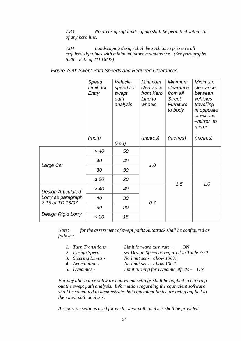
54
7.83 No areas of soft landscaping shall be permitted within 1m
of any kerb line.
7.84 Landscaping design shall be such as to preserve all
required sightlines with minimum future maintenance. (See paragraphs
8.38 – 8.42 of TD 16/07)
Figure 7/20: Swept Path Speeds and Required Clearances
Speed Limit for Entry (mph)
Vehicle speed for swept path analysis (kph)
Minimum clearance from Kerb Line to wheels (metres)
Minimum clearance from all Street Furniture to body (metres)
Minimum clearance between vehicles travelling in opposite directions –mirror to mirror (metres)
Large Car
> 40 50
1.0
1.5 1.0
40 40
30 30
≤ 20 20
Design Articulated Lorry as paragraph 7.15 of TD 16/07 Design Rigid Lorry
> 40 40
0.7 40 30
30 20
≤ 20 15
Note: for the assessment of swept paths Autotrack shall be configured as
follows:
1. Turn Transitions – Limit forward turn rate – ON
2. Design Speed - set Design Speed as required in Table 7/20
3. Steering Limits - No limit set - allow 100%
4. Articulation - No limit set - allow 100%
5. Dynamics - Limit turning for Dynamic effects - ON
For any alternative software equivalent settings shall be applied in carrying
out the swept path analysis. Information regarding the equivalent software
shall be submitted to demonstrate that equivalent limits are being applied to
the swept path analysis.
A report on settings used for each swept path analysis shall be provided.
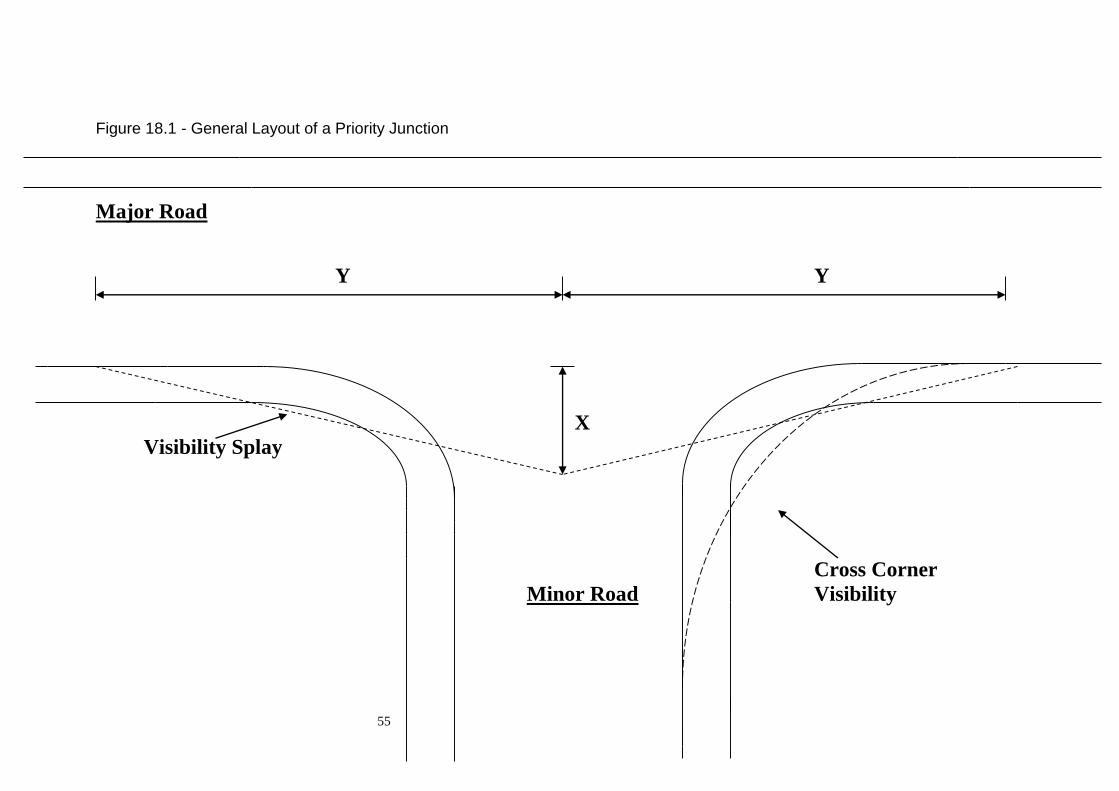
55
Figure 18.1 - General Layout of a Priority Junction
Major Road
Y Y
X
Visibility Splay
Cross Corner
Minor Road Visibility

56
Figure 18.2: Dropped Kerb at Road Junctions Typical Layout
drop kerb
drop kerb
dropped kerb
Housing Road
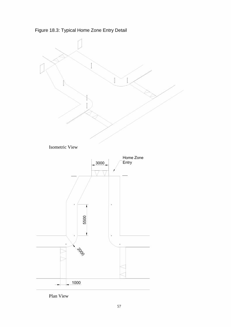
57
Figure 18.3: Typical Home Zone Entry Detail
Isometric View
Plan View

58
Figure 18.4: Markings for use with Give Way Sign
Figure 18.5: Markings for no Give Way Sign
200
600 300
4000
2000
2100 -
2750
300
3750
600
600 300
100
150
(Max
. 15000)

59
19. Turning Areas
19.1. Turning Provision
It is desirable for road layouts to be designed so that service vehicles do not need
to reverse on the public road. Wherever practicable this should be achieved by the
provision of access roads in the form of loops off the LOCAL DISTRIBUTOR
ROADS, thus avoiding the need for turning areas and minimising dead mileage
for delivery and service vehicles.
19.2. Turning Area
In general, roads not of loop form (i.e. culs-de-sac) should preferably terminate in
turning circles, which can be negotiated by all vehicles in forward gear. Where
lack of space precludes the creation of a turning circle, or as a temporary solution
as part of phased development, turning heads may be substituted, but the attendant
dangers of reversing service vehicles should not be over looked. Any cul-de-sac
over 110 metres long should have a turning circle.
19.3. Geometry
The dimensions of turning areas should suit the characteristics of the largest
vehicle making regular use of the facility. In Residential Roads these will
normally be refuse collection vehicles, while in industrial/commercial
development it may be necessary to cater for 15.5 metres long articulated vehicles
or 18 metres long draw-bar trailers. The turning areas detailed in Figures 19.1,
19.2 and 19.3 are based on the turning circles between kerbs of these vehicles.
19.4. Body Overhang
Where there is no adjacent footway, turning areas shall be provided with 2 metres
wide verge or margin to allow for any overhang of vehicle bodies when
manoeuvring.
19.5. Parking
The layout of a development should be designed to discourage casual parking in
turning areas. This may be achieved either by locating turning circles well clear
of frontage development, or by arranging that premises and designated parking
bays take access via the turning area.
19.6. Informal Courtyards
In residential areas the use of less formal shapes for turning heads may be
acceptable. Note that the shape should still incorporate the basic tuning head
dimensions and be formed using standard radius kerbs.
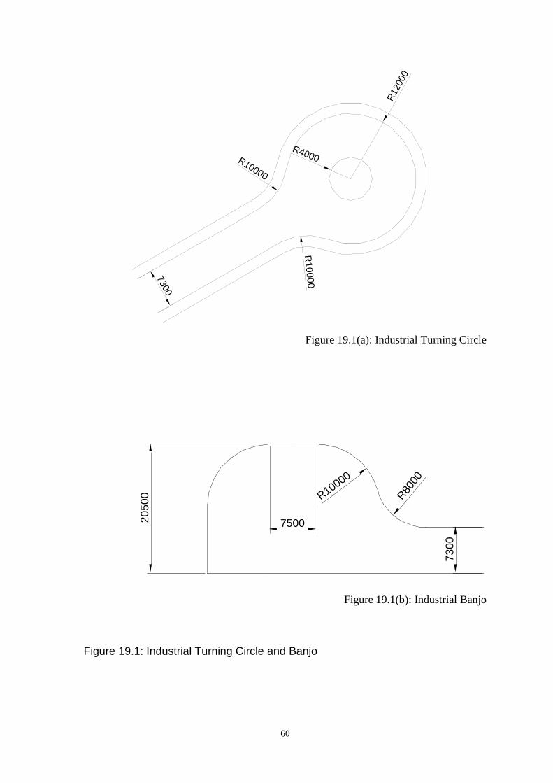
60
Figure 19.1(a): Industrial Turning Circle
Figure 19.1(b): Industrial Banjo
Figure 19.1: Industrial Turning Circle and Banjo
7300
R12000
R10000
R4000
R10000
20
50
0
7500
R10000
R80
00
73
00

61
Figure 19.2(a): Industrial Hammerhead
Figure 19.2(b): Residential Hammerhead
Figure 19.2(a): Residential “Y” Hammerhead
Figure 19.2: Industrial and Residential Hammerhead
53000
73
00
7300
R10
000 R
10000
35000
55
00
5500
R9000 R9000
5500
5500
5500
R80
00
R8000
R8000
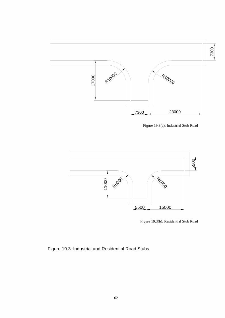
62
Figure 19.3(a): Industrial Stub Road
Figure 19.3(b): Residential Stub Road
Figure 19.3: Industrial and Residential Road Stubs
R10000 R10000
73
00
230007300
17
00
0
R60
00
R6000
5500
5500 15000
11000

63
20. Traffic Calming
20.1. General
All new residential roads within Aberdeenshire Council require to be constructed
in such a manner as to be suitable for a 20mph mandatory speed limit zone. This
speed limit must be self-enforcing and the design of the overall residential road
network must incorporate the necessary features to ensure speeds are kept within
this limit. To comply with the statutory requirements for a 20mph speed limit
zone traffic calming features must be provided at least every 100 metres.
In addition the layout of the residential road network should not encourage
through traffic or inappropriate driver behaviour. Specific traffic calming
measures also have a role to play in this aspect.
20.2. Design Considerations
In assessing the design requirements for any scheme, various factors such as:
(i) Design speed,
(ii) Access for emergency vehicles,
(iii) Pedestrian movements,
(iv) Accessibility,
(iv) Cyclists routes,
(v) Public transport requirements,
(vi) Parking provision,
(vii) Street lighting,
(viii) Environmental features/landscaping,
(ix) Drainage requirements,
will require to be given proper regard and accommodated or provision made for
within the design.
All traffic calming proposals must comply with the relevant legislation and the
Developer is responsible for ensuring compliance.
20.3. Environmental Considerations
Lower vehicle speed will result in a reduction in the number and severity of
accidents. The associated reduction in traffic noise due to the lower speeds will
also be of benefit to residential areas. The relaxation of geometric standards and
the reduction in road widths should allow the developer to incorporate areas for
landscaping and amenity areas. A traffic calmed layout accompanied by
environmental enhancements will help to create residential areas that protect
vulnerable road users such as pedestrians and cyclists.
64
20.4. Application/Hierarchy
Traffic calming measures are applicable to the road hierarchy as described below:
Road Hierarchy Suitability for traffic calming
Primary and District
Distributor Roads
In exceptional circumstances
Local Distributor Roads
Not normally required
Industrial Roads Not normally used in industrial
areas
Residential Roads
Normally required
20.5. Application on Distributor Roads
Where traffic calming is required on Distributor roads it should be used over an
appropriate length and preceded at both ends by a gateway feature. The Roads
Development Engineer will be able to give further guidance of the measures
suitable for particular locations.
20.6. Application to Residential Roads
As indicated previously all RESIDENTIAL ROADS should be designed so as to
restrict vehicles speeds by means of layout or traffic calming measures to allow
for the introduction of a 20mph zone or speed limit. Where a speed limit is
required, it will be a condition of the Construction Consent that a traffic order is
progressed by the Local Roads Authority. A charge of £1414* will be levied
against the Developer for this service. (* Details of the current charge for this
service can be sought from the Roads Development Engineer).
A gateway feature should be used to indicate the entrance to a 20mph zone.
Preferably this will be used at the junction giving access to the area, but can be
used at other locations, at the discretion of the Roads Development Engineer.
20.7. Types of Traffic Calming
Traffic calming features can be divided into 6 main types, namely:
Vertical Measures
Lateral Measures
Measures which affect the carriageway width
Geometric alignment
Measures at junctions
Gateways
Features from these main types are outlined below. It is important to consider the
overall effect of the features proposed on the entire development. Combinations
should be chosen which reduce and restrict the vehicle speeds while protecting
vulnerable road users, such as cyclists and pedestrians. Designs should not rely
solely on conventional traffic calming techniques such as speed cushions and

65
humps; these do little to develop a positive sense of place. Instead, speed
controlling features should be built into the layout of the street, taking advantage
of building alignment, parking, road narrowings, landscaping and other design
features.
Vertical Measures
20.8. Speed Cushion
Speed cushions are suitable for use on any width of road and are particularly
suitable for routes that have high HGV figures or are bus routes.
The maximum vertical displacement of the speed cushion should be 75mm. Each
speed cushion is formed from two taper sections and a raised plateau, as shown in
Figure 20.4. The speed cushions should be placed across the carriageway width in
such a manner as to impede the running line for cars while permitting buses and
emergency vehicles to pass over them. Figure 20.4 shows a typical spacing that
will allow this to occur.
The speed cushions must be designed, signed, and illuminated in accordance with
the Road Hump (Scotland) Regulations 1998, The Road Humps and Traffic
Calming (Scotland) Amendment Regulations 1999 and The Road Humps and
Traffic Calming (Scotland) Amendment Regulations 2002. Reference should also
be made to Transport Scotland’s Good Practice Guide on 20 mph Speed
Restrictions.
20.9. Road Hump
Road humps are suitable for any width of carriageway. They should ideally be
constructed over the entire width of the carriageway, to aid pedestrian movements.
The maximum vertical displacement of the road hump should be 75mm. The road
hump is formed from a circular arc, as shown in Figure 20.1. The erection of
vertical features such as bollards can help to enhance the effectiveness of the road
hump.
The road humps must be designed, signed, and illuminated in accordance with the
Road Hump (Scotland) Regulations 1998, The Road Humps and Traffic Calming
(Scotland) Amendment Regulations 1999 and The Road Humps and Traffic
Calming (Scotland) Amendment Regulations 2002. Reference should also be
made to Transport Scotland’s Good Practice Guide on 20 mph Speed Restrictions.
The use of road humps should be restricted on bus routes.
20.10. Speed Table
Speed tables are suitable for any width of carriageway. They should ideally be
constructed over the entire width of the carriageway, to aid pedestrian movements.
66
The maximum vertical displacement of the speed table should be 75mm. The
speed table is formed from two taper sections and a raised plateau, as shown in
Figure 20.2. An alternative edge detail is shown in Figure 20.3. This allows the
channel line to remain uninterrupted and may aid drainage in certain
circumstances. This layout would be acceptable if predicted pedestrian
movements are low.
The speed tables must be designed, signed, and illuminated in accordance with the
Road Hump (Scotland) Regulations 1998, The Road Humps and Traffic Calming
(Scotland) Amendment Regulations 1999 and The Road Humps and Traffic
Calming (Scotland) Amendment Regulations 2002. Reference should also be
made to Transport Scotland’s Good Practice Guide on 20 mph Speed Restrictions.
The use of speed tables should be restricted on bus routes. Typical Construction
is shown in Figure 20.5.
20.11. Raised Junction
Raised junctions are suitable for any road width. They must be constructed over
the entire junction area; ideally the raised plateau should be extended to at least
the tangent points of the junction radii.
The maximum vertical deflection should be 75mm. The raised junction is formed
by taper sections on each approach to the junction and a raised plateau covering
the entire area, as shown in Figure 20.6. Bollards may be required around the
junction radii to prevent vehicle overrun due to the effective removal of the kerb
upstand.
The raised junction must be designed, signed, and illuminated in accordance with
the Road Hump (Scotland) Regulations 1998, The Road Humps and Traffic
Calming (Scotland) Amendment Regulations 1999 and The Road Humps and
Traffic Calming (Scotland) Amendment Regulations 2002. Reference should also
be made to Transport Scotland’s Good Practice Guide on 20 mph Speed
Restrictions.
Lateral Measures
20.12. Chicanes
Chicanes are not suitable for use on all widths of road. If the road is expected to
carry a high volume of commercial vehicles or if it is a bus route, consideration
should be given to the use of overrun areas.
Chicanes can take many various forms and several types have been outlined
below.
Irrespective of the type of chicane, adequate provision should be made in the
design for cyclists and a separate cycletrack or facility for cyclists to bypass the
feature should be included.
67
The location and spacing of chicanes will be dependent on the road layout and
features but, in general, spacing between chicanes should lie within the range of
40-60 metres.
Some typical layouts for chicanes are shown in Figures 20.7, 20.8 and 20.9. It
should be noted that facilities for cyclists have not be included in these layouts.
The chicanes must be designed, signed, and illuminated in accordance with the
Road Hump (Scotland) Regulations 1998, The Road Humps and Traffic Calming
(Scotland) Amendment Regulations 1999 and The Road Humps and Traffic
Calming (Scotland) Amendment Regulations 2002. Reference should also be
made to Transport Scotland’s Good Practice Guide on 20 mph Speed Restrictions.
Measures which affect carriageway width
20.13. Pinch Points
These are suitable for all widths of road. It is most suited to low volume roads
where the opposing flows are balanced. A typical detail for a pinch point is
shown in Figure 20.10.
If this feature is to be used on a bus route or a route where a large number of
heavy vehicles are expected then consideration should be given to the
incorporation of overrun areas.
Careful consideration must be given to the safe passage of pedestrians and of
cyclists. Separate cycletracks or by pass channels for cyclists should be
incorporated into this form of traffic calming feature to ensure that they are
afforded adequate protection from vehicles.
The pinch must be designed, signed, and illuminated in accordance with the Road
Hump (Scotland) Regulations 1998, The Road Humps and Traffic Calming
(Scotland) Amendment Regulations 1999 and The Road Humps and Traffic
Calming (Scotland) Amendment Regulations 2002. Reference should also be
made to Transport Scotland’s Good Practice Guide on 20 mph Speed Restrictions.
20.14. Pedestrian Refuges/ Traffic Islands
Traffic islands are suitable for use on all categories of roads and should be
provided as an aid to pedestrian movements at locations where a significant
pedestrian movement is anticipated or where difficulty in crossing may be
experienced due to the volume of traffic.
A minimum central island width of 1.5m should be provided with carriageway
widths of 3.0m, with overrun areas extending the carriageway width to 3.5m. A
typical layout is shown on Figure 20.11. It should be noted that facilities for
cyclists have not been included in this layout. Consideration should be given to
the provision of separate cycletracks or a facility for cyclists to bypass the feature.
68
20.15. Carriageway Narrowings
Carriageway narrowings are suitable for all widths of road.
This type of feature is best suited to roads that have relatively balanced vehicular
flows. The correct sitting of these features can also provide significant benefits to
pedestrians by reducing the width of carriageway that they must negotiate.
Careful consideration must be given to the safe passage of cyclists. Separate
cycletracks or by pass channels for cyclists should be incorporated into this form
of traffic calming feature to ensure that they are afforded adequate protection from
vehicles. A typical carriageway narrowing is shown in Figure 20.12
The carriageway narrowing must be designed, signed, and illuminated in
accordance with the Road Hump (Scotland) Regulations 1998, The Road Humps
and Traffic Calming (Scotland) Amendment Regulations 1999 and The Road
Humps and Traffic Calming (Scotland) Amendment Regulations 2002. Reference
should also be made to Transport Scotland’s Good Practice Guide on 20 mph
Speed Restrictions.
Geometric Alignment
20.16. Speed Bend
Speed bends are suitable for bends between 80 and 100 degrees.
Speed bends must be accompanied by good visibility across the bend. In addition,
a 15 metre straight is required between a speed bend and adjacent reverse curve.
A typical layout for a speed bend is shown in Figure 20.13
The speed bend must be designed, signed, and illuminated in accordance with the
Road Hump (Scotland) Regulations 1998, The Road Humps and Traffic Calming
(Scotland) Amendment Regulations 1999 and The Road Humps and Traffic
Calming (Scotland) Amendment Regulations 2002. Reference should also be
made to Transport Scotland’s Good Practice Guide on 20 mph Speed Restrictions.
20.17. Lateral Shift in Alignment
A Lateral Shift in Alignment is suitable for any road width.
The design of the alignment should take full consideration of the type of vehicles
that are likely to use the road. Overrun areas can be incorporated into the lateral
shift to ensure that buses and commercial vehicles can negotiate the feature.
A typical layout for a lateral shift in alignment is shown in Figure 20.14.
The Lateral Shift in Alignment must be designed, signed, and illuminated in
accordance with the Road Hump (Scotland) Regulations 1998, The Road Humps
and Traffic Calming (Scotland) Amendment Regulations 1999 and The Road
Humps and Traffic Calming (Scotland) Amendment Regulations 2002. Reference
69
should also be made to Transport Scotland’s Good Practice Guide on 20 mph
Speed Restrictions.
Measures at Junctions
20.18. Overrun Corners
Overrun Corners can be used at any junction
The design of the overrun feature should comply with Section 20.16. This type of
feature will reduce vehicle speed entering the junction and may be suitable for the
start of a 20mph zone. The overrun area allows larger vehicles and buses to safely
negotiate the junction.
A typical layout for an overrun corner is shown in Figure 20.15.
The Overrun Corners must be designed, signed, and illuminated in accordance
with the Road Hump (Scotland) Regulations 1998, The Road Humps and Traffic
Calming (Scotland) Amendment Regulations 1999 and The Road Humps and
Traffic Calming (Scotland) Amendment Regulations 2002. Reference should also
be made to Transport Scotland’s Good Practice Guide on 20 mph Speed
Restrictions.
Gateways
20.19. Gateway on a Straight
A gateway feature must indicate the start of a 20mph zone.
When used on a straight the gateway should also incorporate a physical speed
reducing feature, as outlined above.
The use of vertical elements such as planting and signing may be useful to
increase the prominence of the gateway.
20.20. Side Road Gateway
The use of a gateway at the junction of a side road will be the most common
usage. Most 20mph zones will start at a junction and vehicle speeds will be low
due to negotiating the junction. Tight radii on the junction and overrun areas may
be used to ensure that vehicle speeds are reduced to an appropriate level.
The gateway should incorporate vertical features that allow signs etc. to be
prominently displayed. The use of vertical features will also increase the
awareness of the driver.
A traffic calming feature will be required soon after the gateway to ensure that
traffic speeds do not increase.

70
Figure 20.1: Round Topped Road Hump
3700
3700
75
2000
5500
2000

71
Figure 20.2: Speed Table
3000 1000
5000
5500
1000
3000 1000
75
1000
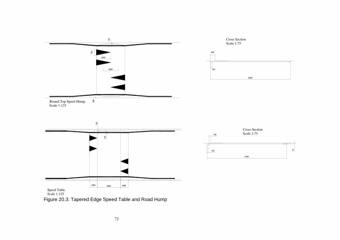
72
Figure 20.3: Tapered Edge Speed Table and Road Hump
300
150
2000
750
1850
150
300
5500
1000 3000 1000
150
150
150
150
75
5500
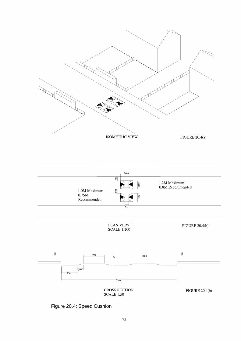
73
Figure 20.4: Speed Cushion
1600
800
750
300
750
1000
5500
1000100
100
75
2400
800
1600
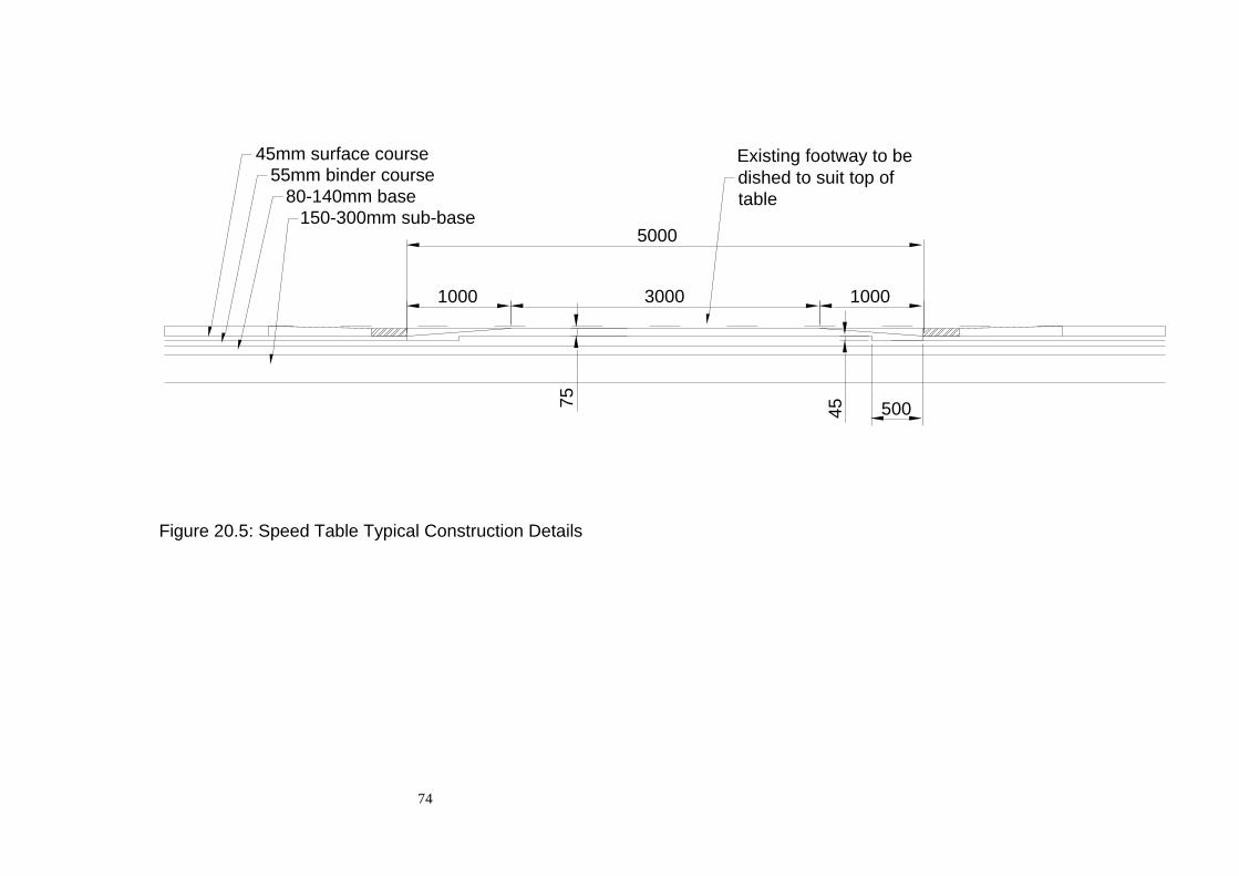
74
Figure 20.5: Speed Table Typical Construction Details
45mm surface course
55mm binder course
80-140mm base
150-300mm sub-base5000
1000 3000 1000
500457
5
Existing footway to be
dished to suit top of
table
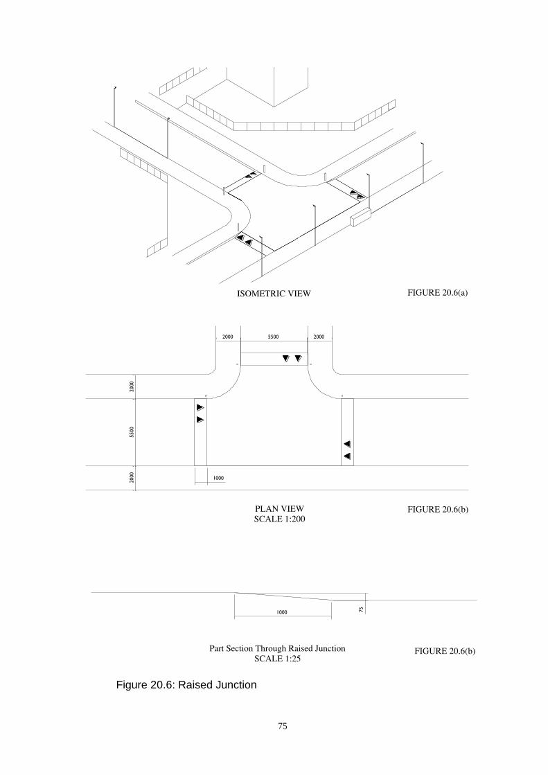
75
Figure 20.6: Raised Junction
5500 20002000
2000
5500
2000
1000
1000 75

76
Figure 20.7: Chicane Type 1
55
00
3000
30
00
30°
35
00
30
00

77
Figure 20.8(a): Isometric View
Taper Angle Corners to be formed
45-90 Deg. by quadrant kerbs
Figure 20.8(b): Plan View
Figure 20.8: Chicane Type 2

78
Figure 20.9: Chicane Type 3
27
50
15
00
8500
125002750
55
00
2750
35
00
30
00

79
Figure 20.10: Pinch Point
5000
5500
2500
3500

80
Figure 20.11: Central Island
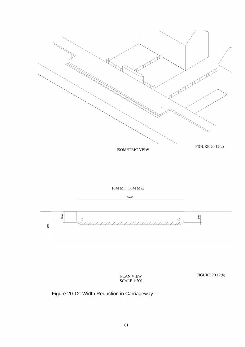
81
Figure 20.12: Width Reduction in Carriageway
20000
2000
500
5500
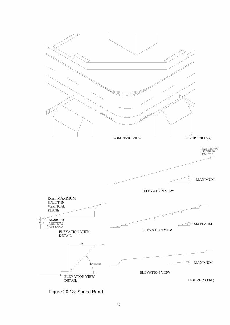
82
Figure 20.13: Speed Bend
15°
15°
45°
6
60
5°
6
15

83
Figure 20.14: Lateral Shift in Alignment
5500
6000
5500
45°
30°
2000
R4500
R6000
(1.42m x W)
(0.42m x W)
R900
Varies
5500
R20000
5500
4500
4500
3000
5500
5500
5500
4500 45002500
R10000
R20000
3000

84
Figure 20.15: Overrun Corners
4100
5500
5500
2000
R4500R10070

85
21. Provision for Pedestrians
21.1. General
(a) Pedestrian movements should be made as convenient, safe and pleasant as
possible by careful attention to the design and layout of pedestrian routes. The
usage dictates the width and the degree of segregation.
(b) Features which will generate or attract pedestrian traffic such as shopping
areas, schools, bus routes, car parks, clinics and parks should be identified at an
early stage in the planning process. These will dictate the main spinal pedestrian
routes which should be segregated as far as possible from major traffic routes and
involve a minimum number of carriageway crossings.
(c) The design of facilities for pedestrians should take account of the requirements
for accessibility set out in the Equality Act 2010 and the recommendations in the
Department for Transport publication “Inclusive Mobility”. This consideration
should include access to public transport and to car parks to provide for integrated
travel facilities.
The Developer will be required to demonstrate compliance with the
requirements of the Disability Discrimination Act by the provision of a
Disability Access Statement. The required procedure for preparation of the
Access Statement is set out in Section 38.
The benefits of providing an accessible environment go beyond those people
meeting the definitions of disability in the Disability Discrimination Act to
include others who are temporarily denied full mobility, such as a parent or carer
pushing a pram, or a person recuperating from an illness. In these circumstances
the simplest of journeys may involve a significant degree of extra effort or even
pain, and the provision of suitable accessibility measures can significantly
improve quality of life.
21.2. Crossing Considerations
Particular attention should be paid to the location at which pedestrian routes cross
carriageways. The choice of location should ensure that pedestrians are not
exposed to unappreciated dangers. The appropriate use of hard and soft
landscaping techniques can guide pedestrians to suitable crossing locations and
help to prevent children running directly onto the carriageway. Careful
consideration should be given to the location of pedestrian traffic generators, such
as shops and leisure facilities, and the pedestrian routes should be designed to
ensure there is an element of control over the locations where pedestrians will
cross the carriageway.
21.3. At Grade Pedestrian Crossings
At designated pedestrian crossing points, kerbs must be dropped as shown in
Figure 25.4 to permit easy access to and from the carriageway for pedestrians with
prams and wheelchairs.

86
21.4. Grade Separated Pedestrian Crossings
Where both pedestrian and vehicular traffic flows are very high it may be
appropriate to consider underpasses or footbridges as carriageway crossings.
These facilities should be designed in such a manner as to be more appealing to
use than any other alternative route. The successful location of such facilities will
require careful consideration to meet the aspirations for a fully accessible built
environment.
21.5. Controlled Pedestrian Crossings
Where grade separation cannot be justified or provided it may be necessary to
consider the use of controlled pedestrian crossing facilities. E.g. a Ped-X or zebra
crossing. In considering the appropriate form of crossing reference should be
made to the Aberdeenshire Council assessment criteria, based on predicted
pedestrian and traffic flows. A tactile surface should be provided on the approach
to all controlled crossings and further guidance on the layout of tactile slabs is
available in the Department for Transport’s “Guidance on the Use of Tactile
Paving Surfaces.”
In addition to this a high skid resistant surfacing material should be used on the
approaches to any controlled crossing. Further guidance on this matter should be
sought from the Roads Development Engineer.
21.6. Possible Enhancements to at Grade Pedestrian Crossings
Uncontrolled at grade crossings may be required where flows do not justify the
provision of grade separated or controlled crossings. This type of crossing may be
improved by the inclusion of a traffic calming feature which makes it easier for
pedestrians to cross the road. On all routes of Distributor Road classification or
higher, tactile paving must be incorporated into the design of the crossing point, in
accordance with the Department for Transport’s “Guidance on the Use of Tactile
Paving Surfaces”. Tactile paving should be used, on all road classifications, at
crossing points where the crossing is perpendicular to the main pedestrian flow,
i.e. a pedestrian refuge.
21.7. Routes on Distributor Roads
Where pedestrian routes of necessity run beside Distributor Roads, they shall be
separated from the carriageway by a verge at least 2 metres wide in the interests of
road safety and of improving the environment of the road.
21.8. Footway Widths
The general width of footways is set out in Section 15. These widths may require
to be increased to cater for high pedestrian volumes. Conversely, at the discretion
of the Roads Development Engineer, footways may be reduced in width over
short lengths not exceeding 3 metres to negotiate mature trees and other
obstructions, but they shall at no point be less than 1.4 metres wide. Where
87
Statutory Undertakers' services are contained in the footway, special arrangements
may be necessary at sections of reduced width.
21.9. Vehicular Footway Crossings
Where vehicular access is taken across a footway, the ramp will be confined to the
front portion of the footway, thus emphasising pedestrian priority. (See Figure
25.3). The reduced length of ramp also helps to encourage a reduction in the
speed of vehicles crossing the footway.
21.10. Gradients
Gradients on both footways and footpaths should not normally exceed 5 per cent.
Steeper gradients require the specific approval of the Roads Development
Engineer, but these sections will be considered as ramps and the criteria set out in
Section 21.12 will be applied.
21.11. Baffle Barriers
Situations where long lengths of public footpath meet a road at right angles should
be avoided because of the inherent dangers of children moving at speed towards
the road ahead. Where the situation is unavoidable, pedestrian guardrails or baffle
barriers should be considered and incorporated into the layout at the design stage.
The barriers need not be in railing form but should be constructed in a way that is
compatible with their surroundings and agreed with the Roads Development
Engineer. Where a railing is proposed it should normally be constructed of tubular
galvanised steel. An alternative may be acceptable at the discretion of the Roads
Development Engineer.
Dimensions will vary according to the site but a typical layout would be as shown
in Figure 21.1. The design should take account of the requirement of accessible
design in para 21.1 above. If baffle barriers are to be used access for maintenance
vehicles must be provided.
21.12. Ramps and Steps
Pedestrian ramps and steps shall comply with the geometric standards and
recommendations set out in the Department for Transport publication “Inclusive
Mobility”.
21.13. Disabled Access to Buildings
For disabled access to buildings ramps should be incorporated off road. Where
this is not practicable the Roads Development Engineer should be consulted to
discuss options for formation of access ramps on the footway.
Reference should be made to the Building (Scotland) Regulations Technical
Handbooks and the Institution of Highways and Transportation publication
“Guidelines for Reducing Mobility Handicaps” for further details of required
provision.

88
21.14. Obstacles to Pedestrian Routes
Any street furniture, which is to be provided, such as planters and waste paper
bins, should be located in such a way as to maintain a 2 metre wide obstacle free
footway.
Not only is this required to facilitate pedestrian movement but is also required to
allow mechanised maintenance.

89
Figure 21.1: Typical Baffle Barrier Layout
1000
Varies
1000
1000
1500
Var
ies
Var
ies
Var
ies
Varies
1000
2000
Varies
Varies
1000
90
22. Provision for Cyclists
22.1. General
A cycle network should be established to cater for the needs of cyclists. The
network should link residential areas to shopping areas, schools, bus routes,
clinics, parks etc.
In residential areas, with a design speed of 20 mph or less, separate cycle facilities
will not normally be required. At this reduced speed cycles and vehicular traffic
can safely share the same carriageway space.
The Developer will be required to provide a Cycle Audit to demonstrate that the
full needs of cyclists have been considered in the overall design of the
Construction Consent.
It should be noted that combined footways/cycletracks will require to be the
subject of a formal Traffic Order and signed in accordance the current version of
The Traffic Signs Regulations and General Directions. The Developer will be
liable for the costs associated with the required Traffic Order and route signage.
22.2. Objectives
The cycle network should meet the following main objectives:
i) Cyclists should be segregated from large volumes of vehicular
traffic, especially where vehicle speeds are in excess of 40mph.
ii) Vehicle speeds should be reduced where there are large volumes of
cyclists.
iii) Safe crossing points should be provided for cyclists at roads with
high traffic flows.
Further advice can be obtained from the Institution of Highways and
Transportation Guidelines “Cycle-friendly Infrastructure – Guidelines for
Planning and Design” and Transport Scotland’s “Cycling by Design – 2010”
22.3. Infrastructure Requirements
In order for cycling routes to be safe, convenient and attractive the following five
criteria should be considered and met:
Coherence: The cycling infrastructure should form a coherent entity, linking all
significant trip origins and destinations, routes should be continuous and
consistent in standard.
Directness: Routes should be as direct as possible, based on desire lines-
detours and delays will deter use.

91
Attractiveness: Routes must be attractive to cyclists on subjective as well as
objective criteria: lighting, personal safety, aesthetics, noise and integration with
the surroundings are important.
Safety: Designs should minimise casualties and perceived danger for
cyclists and other road users.
Comfort: Cyclists need routes that are smooth, with well-maintained
surfaces, flush kerbs, regularly swept, and with gentle gradients; routes must be
convenient to use and avoid complicated manoeuvres and interruptions.
22.4. Cycle Audit Procedure
As stated earlier a Cycle Audit will be required with each Construction Consent
application.
Cycle Audits should be carried out in accordance with “Guidelines for Cycle
Audit and Cycle Review”, published by the Institution of Highways and
Transportation, 1998.
All new developments should be considered to carry a Cycle Friendly
classification in accordance with the above guidelines. In most cases it will be
appropriate for CAP3 and CAP4 audits to be carried out.
For larger developments the Roads Development Engineer may require a CAP 1
audit to be provided as part of any Traffic Impact Assessment.
Early consultation with the Roads Development Engineer is essential in this
matter
22.5. Definitions
The following definitions apply to cycling facilities:
i) A cycle track has the same meaning as described in the Roads
(Scotland) Act 1984. It is therefore a “road” for cyclists or cyclists and
pedestrians segregated from the carriageway.
ii) A cycle lane is a lane provided for cyclists within a carriageway.
A cycle route is a combination of these facilities.
22.6. Format
In most circumstance the appropriate format of cycle track will be of the shared
use type. It is also anticipated that most cycle tracks will comply with the
requirements of un-segregated cycle tracks. To allow the free movement of
cyclists and pedestrians the shared facility will be 3.0 metres wide with at least a
0.5m buffer zone between it and the carriageway.

92
If a segregated facility is required it should meet the standards set out in Table
22.1
Table 22.1 – Cycle Track Widths
Segregated
Boundary
conditions
Footway/
Footpath
Cycletrack Verge Shared
Open site 1.2m 1.3m - 2.5m
Walls,
bushes
1.2m 1.5m - 2.7m
Carriageway 1.2m 1.5m 0.5m 3.2m
22.7. Signing
Signing will require to be erected on any cycle network. Early contact should be
made with the Roads Development Engineer to determine the exact provision
required. All signing must comply with the current version of the Traffic Signs
Regulations and General Directions.
22.8. Surface
Surfacing for a shared use facility may be of a standard footway construction
according to the developer's intended footway material.
NB conventional or small element slab construction is not suitable for shared use.
22.9. Junctions
Kerbs must be dropped at crossing points. Where a signalled controlled crossing
facility is required on a shared use facility a TOUCAN crossing should be
considered. Consideration should be given to the priority at intersections between
cycle tracks and roads. It may be appropriate for the cycle track to have right of
way in certain circumstances. Reference should be made to current good practise
guides for further information on this particular aspect.
22.10. Parking
Parking facilities for cyclists should be secure and convenient otherwise they will
be underused and cycles will be parked in a haphazard fashion. Devices to
support cycles should be appropriately located to minimise damage and maximise
security against theft and vandalism. Currently the favoured style of cycle stand is
the Sheffield, Figure 22.1, although other forms will be considered. Parking
standards for bicycles should be as detailed in the current version of “Car Parking
Standards for Development Control in Aberdeenshire”.

93
22.11. Lighting
Lighting shall be installed on combined footpaths/cycletracks to comply with the
requirements of BS 5489.
22.12. Traffic Orders
It should be noted that combined footways/cycletracks will require to be the
subject of a formal Traffic Order and signed in accordance the current version of
The Traffic Signs Regulations and General Directions. The Developer will be
liable for the costs associated with the required Traffic Order and route signage.
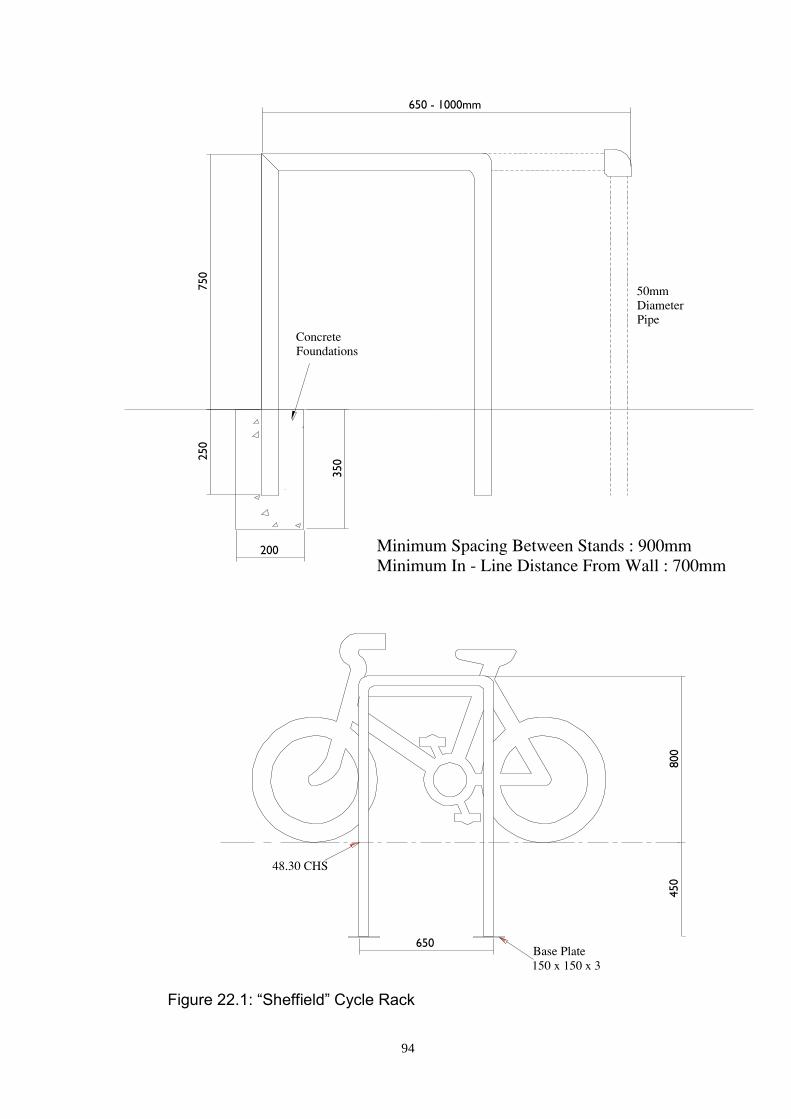
94
Figure 22.1: “Sheffield” Cycle Rack
200
3502
50
750
650 - 1000mm
450
650
800

95
23. Rural Areas
23.1. Introduction
This guide is predominately targeted at the urban development situation and its
immediate environs. Areas of a rural nature require to be considered somewhat
differently.
23.2. Hierarchy
Circumstances when rural standards may be applied should be discussed at an
early stage, and may include:
i) Developments from an unrestricted road;
ii) Developments which are likely to remain remote from the existing
settlement for the foreseeable future.
Rural areas can be treated as having a similar hierarchy as to the urban areas.
However the increased traffic speeds on unrestricted roads should be regarded as a
significant factor and care must be taken to ensure that adequate visibility is
provided to take account of this.
23.3. Road Width
Within this document road widths have been specified to take account of the
likely traffic generated by the development. This basic premise will hold for rural
development except the restrictions on overall length of road will be relaxed.
Using this method Table 23.1 below indicates alternative road widths based on
number of dwellings:
Table 23.1 - Road Widths
< 15 dwellings 3.5m single track access road with passing places
> 15 dwellings 5.5 metre wide carriageway
23.4. Development on Existing Roads
Where a development is proposed on a road which does not meet these criteria
then the developer will be required to widen the road along the frontage of the
development or the access road to the development to the appropriate width.
23.5. Passing Places
All passing places in rural areas should be constructed to the dimensions given in
Figure 23.1. All passing places must be intervisible and spacing shall not exceed
150 metres . The Developer will be responsible for signage in accordance with
the current version of the Traffic Signs Regulations and General Directions.
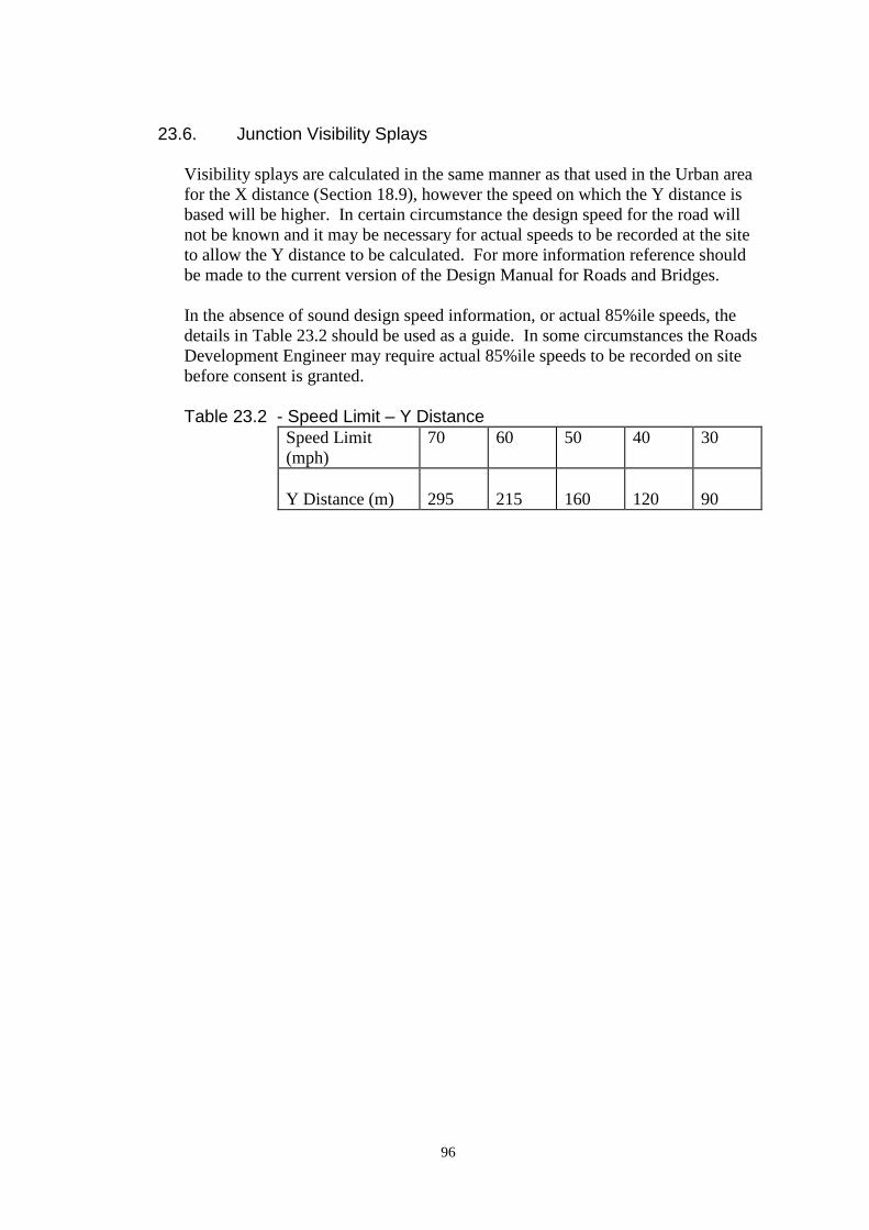
96
23.6. Junction Visibility Splays
Visibility splays are calculated in the same manner as that used in the Urban area
for the X distance (Section 18.9), however the speed on which the Y distance is
based will be higher. In certain circumstance the design speed for the road will
not be known and it may be necessary for actual speeds to be recorded at the site
to allow the Y distance to be calculated. For more information reference should
be made to the current version of the Design Manual for Roads and Bridges.
In the absence of sound design speed information, or actual 85%ile speeds, the
details in Table 23.2 should be used as a guide. In some circumstances the Roads
Development Engineer may require actual 85%ile speeds to be recorded on site
before consent is granted.
Table 23.2 - Speed Limit – Y Distance
Speed Limit
(mph)
70 60 50 40 30
Y Distance (m)
295
215
160
120
90

97
Figure 23.1: Typical Passing Place Detail
98
24. Making Up and Adoption of Private Roads
24.1. Introduction
In accordance with the terms of the Roads (Scotland) Act 1984 the Local Roads
Authority is required to maintain a list of roads for which they have the
responsibility of management and maintenance, the Statutory List of Public
Roads. Section 151 of the Act refers to these roads as “Public Roads”.
“Private Roads” are any way over which there is a public right of passage, other
than a Public Road.
24.2. Additions to the Statutory List of Public Roads
Provision is contained within The Roads (Scotland) Act 1984 for Private Roads to
be added to the Statutory List of Public Roads. The provisions are outlined in
Sections 1(4), 16 and 17(3)(c)(iii).
Any road to be considered for addition to the Statutory List must be completed to
the standard required by the Local Roads Authority for that particular
classification of road. This assessment will also take into account the urban or
rural nature of the surrounding locus.
24.3. Request for Addition to the Statutory List
An application can be made to the Local Roads Authority for a Private Road to be
adopted, i.e. added to the Statutory List of Public Roads. Once the statutory
procedures have been successfully completed the road will become a Public Road
and become the responsibility of the Local Roads Authority for management and
maintenance.
Such an application must be supported by “the requisite number” of frontagers.
The “requisite number” of frontagers is defined “as a majority or such number as
together owns land which includes not less than half the boundary between the
land fronting or abutting the relevant road and that road” Further guidance on this
can be found in The Roads (Scotland) Act 1984, Section 1(7), as amended by the
Abolition of Domestic Rates Etc (Scotland) Act 1987, Schedule 6.
The Local Roads Authority must be satisfied that the application has the support
of the requisite number of frontagers and may take steps to ascertain this.
24.4. Section 13 Notice
Following a competent request for adoption the Local Roads Authority will carry
out an inspection of the road to ascertain if it is constructed to the required
standard.
If this inspection shows that it is to the required standard the road will be added to
Statutory List of Public Roads within 12 months of a competent application.

99
However, if this inspection shows that works are required to bring the road up to
the required standard the Local Roads Authority will issue a notice under The
Roads (Scotland) Act 1984, Section 13 (a Section 13 Notice) to the frontagers.
A Section 13 Notice requires the frontagers to make up the road to the required
standard. The notice will specify the following:
1) The Local Roads Authority’s estimate of the cost of the required
works
2) A scheme apportioning the cost among the frontagers. The scheme
must be equitable in the opinion of the Local Roads Authority and it must
describe for each frontager the proportion of the costs to be paid by him
3) The dates by which the works shall be commenced and completed.
If the terms of the notice are not met the Local Roads Authority has the power to
carry out the works or complete any unfinished works. The expenses incurred by
the Local Roads Authority are recoverable in accordance with the terms of the
Section 13 Notice.
24.5. Appeals Against a Section 13 Notice
Any person receiving a Section 13 Notice may appeal by summary application to
the sheriff within twenty-eight days of the date of service of the notice. The
sheriff’s decision is final.
24.6. Maintenance Period
Once the road is in a condition acceptable to the Local Roads Authority it must be
added to the Statutory List of Public Roads within twelve months.
24.7. Required Standards
The required standards for the road to be adopted will be set out in the Section 13
Notice. In general terms the road shall comply with the standards set out in the
Tables below. It should be noted however that the Roads Development Engineer
has discretion to relax these conditions to take account of local factors relating to
the road in question.
24.8. Required Surface Condition
The surface must be in good condition and free from potholes or any major
surface deterioration. If this is not the case the surface will require to be renewed
and the Section 13 Notice will include for the cost of any such repairs.

100
Table 24.1 Adoption Criteria - Urban Private Roads
Feature Standard Comment
Carriageway Width 5.5m
May be reduced at the discretion
of the Roads Development
Engineer, if traffic flows are very
low.
Minimum Camber/Crossfall 2.5%
Maximum Gradient 5.5% May be increased over short
lengths at the discretion of the
Roads Development Engineer.
Minimum Gradient 0.8% Minimum practical for drainage
channels.
Minimum Vertical Curve
Length
K x algebraic
difference in %
gradient
Where K = 3; absolute minimum
length = 15m.
Minimum Horizontal Curve
Radius
15m Except speed control bends
Superelevation not essential.
Minimum Sight Distance See 16.6 Design Speed to be based on
85%ile speed
Junction Visibility See Table 18.1 See Section 18 for relaxations.
Turning Area Provision as outlined
in Section 19 will be
required.
Footways 2m On both sides. Possible
relaxation to 1.8m on one side, or
in exceptional circumstances no
footway, allowing a shared
surface approach, only at the
Roads Development Engineer’s
discretion.
Drainage Comply with Section
31 of this guide.
Minimum requirement is a system
to remove standing water from
the carriageway surface.
Lighting Comply with Section
32 of this guide.
At the discretion of the Roads
Development Engineer.
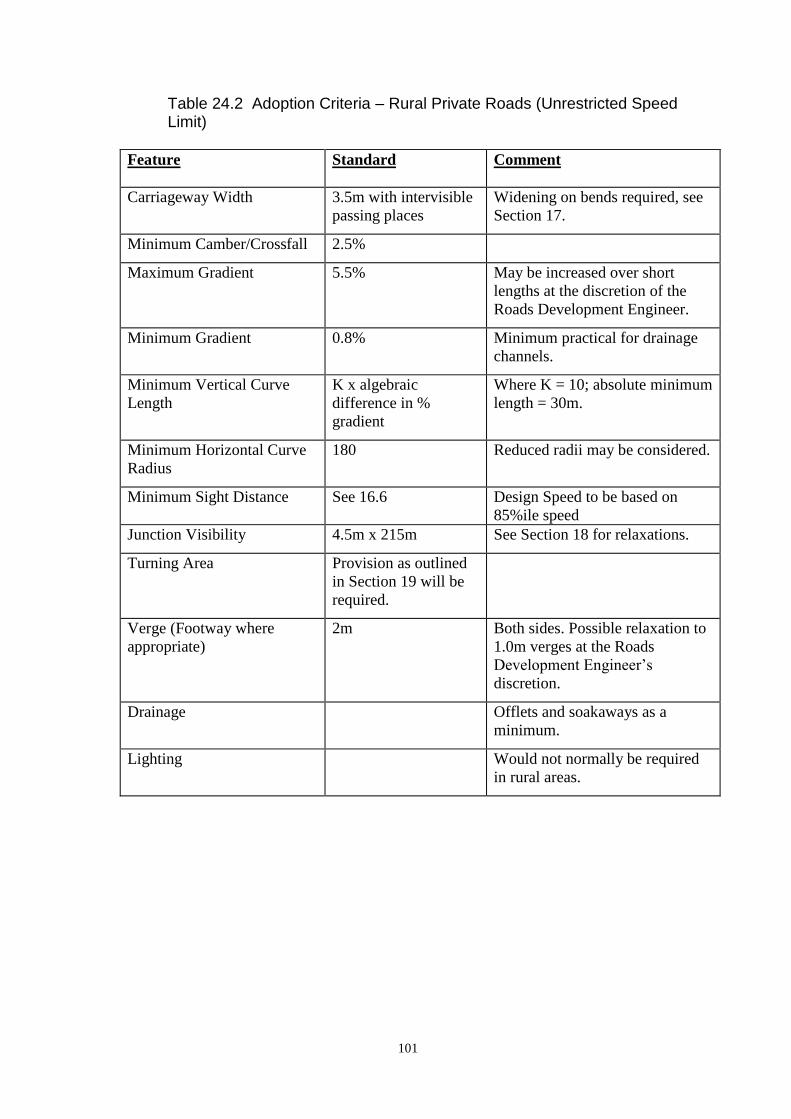
101
Table 24.2 Adoption Criteria – Rural Private Roads (Unrestricted Speed Limit)
Feature Standard Comment
Carriageway Width 3.5m with intervisible
passing places
Widening on bends required, see
Section 17.
Minimum Camber/Crossfall 2.5%
Maximum Gradient 5.5% May be increased over short
lengths at the discretion of the
Roads Development Engineer.
Minimum Gradient 0.8% Minimum practical for drainage
channels.
Minimum Vertical Curve
Length
K x algebraic
difference in %
gradient
Where K = 10; absolute minimum
length = 30m.
Minimum Horizontal Curve
Radius
180 Reduced radii may be considered.
Minimum Sight Distance See 16.6 Design Speed to be based on
85%ile speed
Junction Visibility 4.5m x 215m See Section 18 for relaxations.
Turning Area Provision as outlined
in Section 19 will be
required.
Verge (Footway where
appropriate)
2m Both sides. Possible relaxation to
1.0m verges at the Roads
Development Engineer’s
discretion.
Drainage Offlets and soakaways as a
minimum.
Lighting Would not normally be required
in rural areas.
102
25. Vehicular Access to Premises and Servicing Arrangements
25.1. Access to Premises
Vehicular access to residential and minor commercial premises will normally be
taken from the public road via a footway crossing designed to cater for the traffic
volume and maximum weight of vehicle anticipated (Sections 30.19 to 30.22).
For major commercial and industrial development, however, access should be by
means of "service roads" connecting to the main road network at a T-junction
designed as detailed in Section 18. In the case of larger retail warehouses,
supermarkets and superstores, it is essential for service access to be segregated
from access to customers' parking areas in the interest of operational convenience
and of safety.
25.2. Service Roads
Service roads shall be designed to at least INDUSTRIAL ACCESS ROAD
standards (Section 11), with particular attention to widening on small radius bends
(Section 17) and turning areas (Section 19).
25.3. Driveways
Private driveways should normally meet the road at right angles and be at least 15
metres from the nearest junction along the secondary road. Driveways should be
positioned to enable the required visibility standards to be achieved. A crossing of
the footway will be required and this should be constructed in accordance with
Figure 25.3.
A 3 metre length beyond the paved road areas should be paved to prevent
deleterious material (e.g. loose chippings) being carried on to the road. In rural
areas this may be required to be extended to 5-10 metres (at the discretion of the
Roads Development Engineer). Severe gradients, which render driveways
unsuitable for car parking, should be avoided wherever possible (1 in 20
desirable). Driveways must be internally drained.
House driveways should be providing a hardstanding of sufficient size to provide
the parking provision detailed in the current version of “Car Parking Standards for
Development Control in Aberdeenshire”. Should garage facilities be provided
within the site, this length may be reduced accordingly. For new properties a
minimum length of 6.0 metres should normally be used to allow for an adequate
parking space for one vehicle in front of a garage, this may be reduced to 5.5
metres in certain circumstances. For existing properties a minimum length of 5.0
metres should be used.
25.4. Service Areas
Service areas range from single parking bays for delivery vehicles to sophisticated
structures incorporating loading bays and mechanical goods handling equipment.
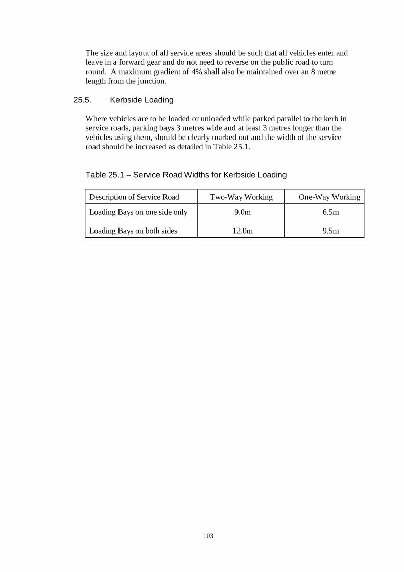
103
The size and layout of all service areas should be such that all vehicles enter and
leave in a forward gear and do not need to reverse on the public road to turn
round. A maximum gradient of 4% shall also be maintained over an 8 metre
length from the junction.
25.5. Kerbside Loading
Where vehicles are to be loaded or unloaded while parked parallel to the kerb in
service roads, parking bays 3 metres wide and at least 3 metres longer than the
vehicles using them, should be clearly marked out and the width of the service
road should be increased as detailed in Table 25.1.
Table 25.1 – Service Road Widths for Kerbside Loading
Description of Service Road Two-Way Working One-Way Working
Loading Bays on one side only
Loading Bays on both sides
9.0m
12.0m
6.5m
9.5m
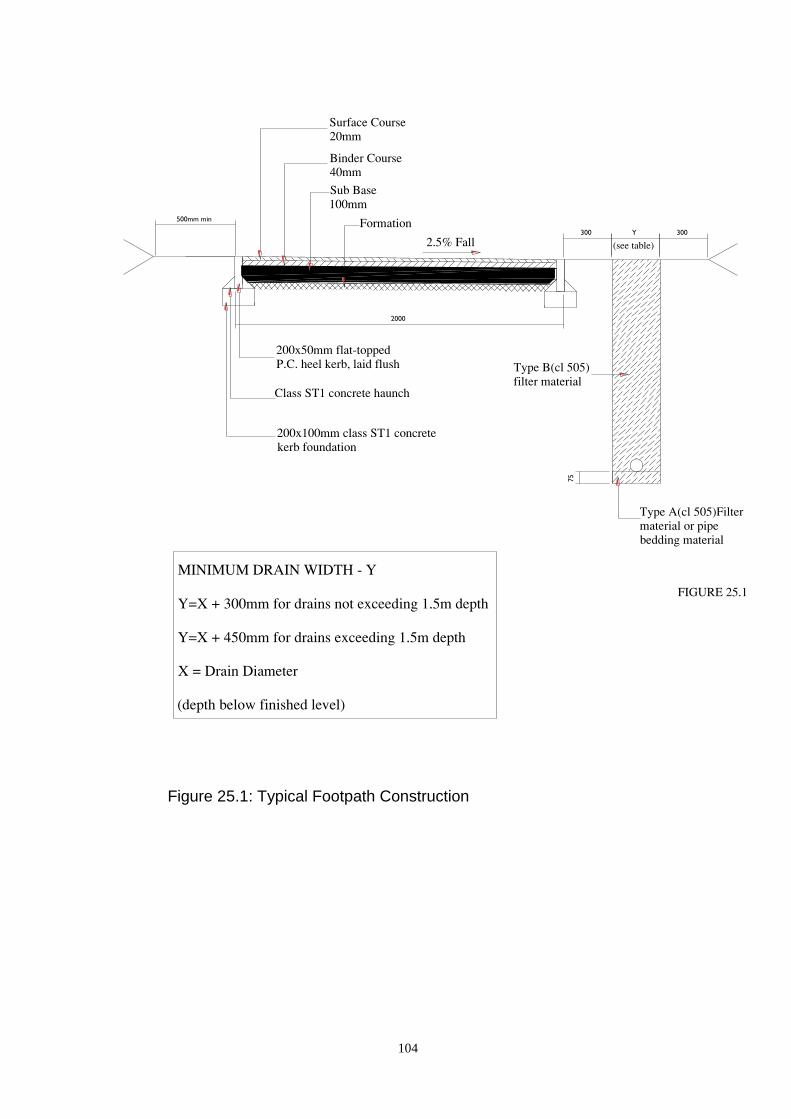
104
Figure 25.1: Typical Footpath Construction
2000
500mm min
300 300
75
Y

105
Figure 25.2: Kerb Details
125
25
300
600
150
95
25
80
100
25 300
150
500
95
25
100
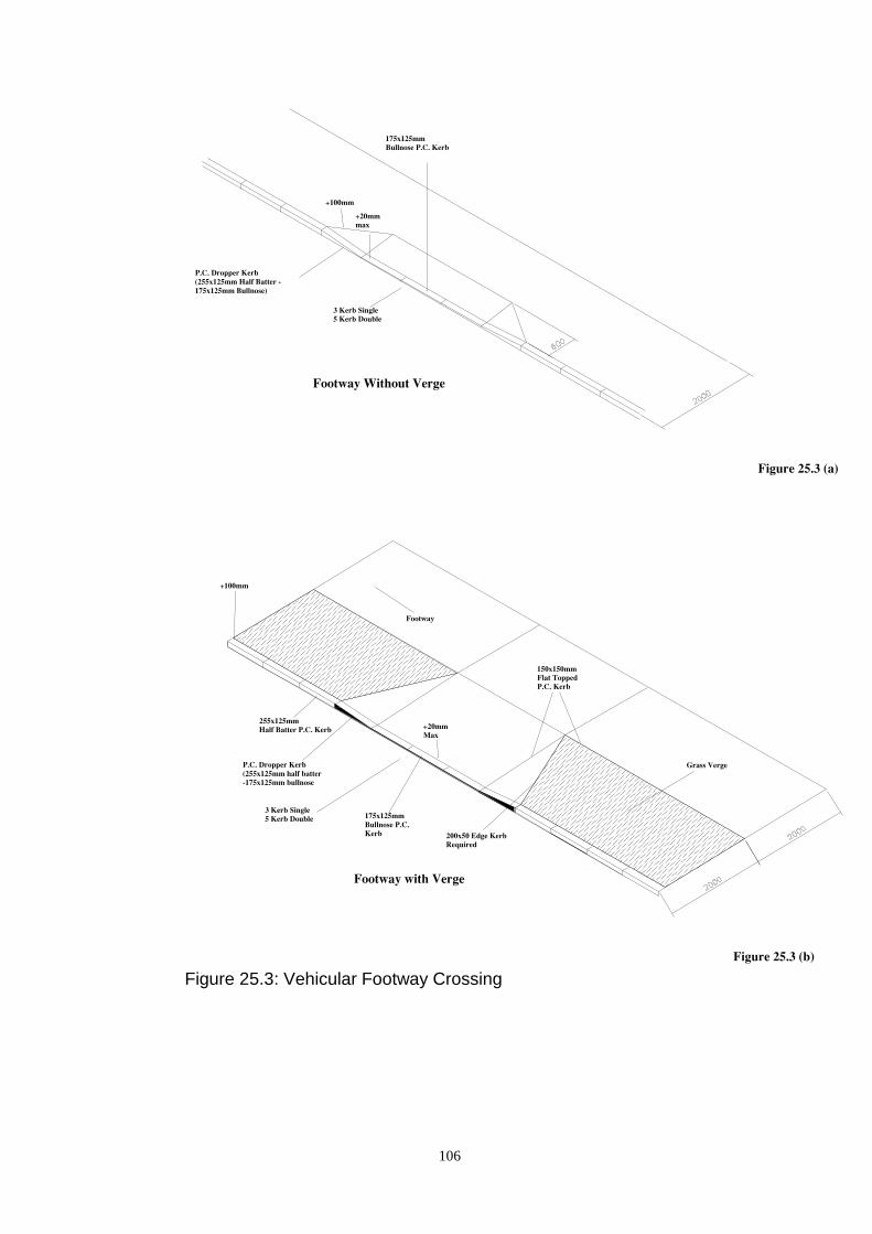
106
Figure 25.3: Vehicular Footway Crossing

107
Figure 25.4: Dropped Kerb Detail at Designated Pedestrian Crossing Point
108
26. Car Park Provision
26.1. Level of Provision and Adoption Criteria
In general, adequate off-road parking should be provided adjacent to all new
developments to ensure that vehicles are not parked on the road where they may
impede traffic flow and constitute a safety hazard. The levels of provision
detailed in the current version of Car Parking Standards for Development Control
in Aberdeenshire shall be used.
The suitability of parking areas for adoption will be determined in accordance
with the guidance given in Section 3.4 of this guide.
26.2. Rehabilitation
Whenever existing buildings are rehabilitated or modernised, the opportunity
should be taken to provide parking at the level required for comparable new
development. This may involve the selective demolition of certain derelict
buildings, utilisation of former garden ground or some adjustment of road
boundaries to create off-road parking areas.
26.3. Location
The location of car parking areas in a development should be considered at an
early stage in the design process to achieve a balanced distribution of spaces
throughout the site, conveniently related to user destinations. Pedestrian access to
premises should be so arranged that it is easier and more convenient to use the
designated parking areas than to park casually on the road with special
consideration given to the needs of disabled people.
26.4. Residents' Parking
Parking spaces reserved for the exclusive use of certain proprietors and/or
their guests should be located within the property curtilage wherever
possible. This is most readily achieved by the provision of private driveways
(Section 25.3) and/or individual garages/carports. Failing this, the location and
surface treatment of off-road parking areas provided in lieu of the above should
emphasise their private nature.
26.5. Visitors' Parking
Parking areas provided for communal use by casual visitors should be located so
as to be obvious to strangers to the development. It will often be appropriate for
such public parking to be located in lay-bys, particularly since their presence can
positively discourage indiscriminate kerbside parking elsewhere on the road. In
general terms provision of 1 space per four dwellings should be sufficient,
however further guidance on this can be sought from the Roads Development
Engineer.
109
26.6. Walking Distances
Residents' parking spaces should be situated no more than 30 metres walking
distance from the main entrance to the dwelling they serve, and the maximum
distance for visitors' spaces should be similarly limited to 100 metres.
Consequently, where lock-up garages are provided at some distance from the
dwellings they serve, other off-road areas may be required for the convenient
parking of residents' cars.
26.7. Bay Sizes
The size of the standard car in the UK is approximately 4.75 metres x 1.8 metres.
Allowing suitable clearances all round and for the opening of doors, the minimum
design module for car parking bays shall be 5 metres x 2.5 metres with a 6m aisle.
Longer bays will be required in certain situations (e.g. lay-bys).
26.8. Disabled Persons
About 5% of parking should be reserved for disabled persons. The location and
layout of parking spaces for disabled people should be designed in accordance
with the recommendations in the Department for Transport publication “Inclusive
Mobility”.
26.9. Car Park Layouts
Typical layouts for off-road parking areas are shown in Figure 26.1. It should be
noted that angled parking layouts tend to be appreciably less efficient in land-use
than 90º parking layouts even with the narrower aisle widths possible with single-
way working. The use of angled parking may, however, be appropriate on narrow
sites.
26.10. Large Car Parks
In industrial, commercial and shopping developments, parking provision will
normally be in the form of either large surface or multi-storey car parks. The
layout will depend upon operational requirements, particularly where it is
proposed to control entry and exit by means of barriers, with adequate space
provided to ensure that any queues which develop do not extend on to the public
road.
26.11. Access
Vehicular access to off-road parking areas will normally be taken from the public
road via a footway crossing (Figure. 25.3). However, for large car parks, liable to
generate substantial traffic flows, access shall be taken via a road junction formed
in accordance with Section 15. In such cases the car park access shall be
constructed to CORE ROAD standards although a reduced width may be
appropriate where one-way operation is to be enforced.

110
26.12. Lay-by Parking
The layout of lay-by parking areas is dependent on the road type and the traffic
flow: on CORE ROADS lay-by parking shall normally comprise bays, 6 metres
long x 2.5 metres wide, located parallel to the carriageway and having 6m long
splays at both ends.

111
Figure 26.1: Off Road Parking Areas

112
Other Design Requirements
27. Statutory Undertakers’ Services
27.1. Provision
The provision of statutory or other services laid underground constitutes a basic
element of development design. The Statutory Undertakers, who provide such
services, must therefore be consulted during preparation of design briefs, so that
their requirements can be co-ordinated in the design and a balance struck between
their needs and other objectives.
27.2. Routeing
In the interests of both the Statutory Undertakers and their consumers all mains
and services serving more than one proprietor should be located in land which is
readily accessible. It has been recognised that these criteria are best met by public
roads and, as well as making provision for pedestrian and vehicular movement; it
is therefore a function of most roads to provide routes for underground services.
27.3. Routeing in Home Zones
Areas to allow routeing of Undertakers’ services must form an integral part of any
HOME ZONE design. Early consultation with all the Statutory Undertakers will
be crucial in the delivery of a successful Home Zone development.
27.4. Location
Sewers will normally be placed under the carriageway and early consultation
should be made with Scottish Water regarding that Authority's provision, in
accordance with the Sewerage (Scotland) Act 1968, of surface water sewers, for
the drainage of roofs and paved areas within the curtilage of premises, and the
foul water drainage system. All services other than sewers, and occasionally
water mains shall be grouped in "service corridors" located within the limits of
footways, verges, adoptable footpaths (Section 3.3) with a minimum of service
connections across the carriageway. Refer to Section 18 for specific requirements
for plant location in roundabouts.
27.5. Service Corridors
The width of a service corridor will depend on the number and type of premises
served. Normally, all domestic services (gas, electricity, lighting, water and
telephones) will be accommodated in a 2 metres wide reservation and Figure 27.1
shown typical positions, the minimum clearance between each service being to the
satisfaction of the Statutory Undertakers. This diagram is, however, only a guide
and does not absolve the designer from negotiating with each of the Statutory
Undertakers in turn at the earliest possible stage since, in any development, the
depth, clearance and relative position of each service will require to be decided by
the Statutory Undertakers, and the method of laying cables and pipes left to their

113
discretion. Special arrangements will require to be made where a footway is less
than 2.0 metres wide, and local widening in excess of 2.0 metres may be
necessary to accommodate access chambers or where roads have tight bends.
27.6. Road Furniture and Lighting
All road furniture should normally be located at the rear of footpaths/footways or
recessed behind them and no furniture or structures should obstruct any road
junction sight line. Conversely, no services other than road lighting cables should
be located within 0.5 metre of the rear of the footway to allow for lighting
columns and joint pillars or other road furniture. Detailed guidance regarding the
provision of road lighting is contained in Section 32.
27.7. Maintenance Access
Ready access must be available at all times to all parts of service routes for
maintenance and in cases of emergency. Lorry access will be needed to some
places such as manholes, electricity sub-stations, Telecommunication junction
boxes and gas governor house installations; and the Statutory Undertakers'
requirements for such facilities should be ascertained at an early stage. They
should be positioned so as to minimise disruptions to vehicle and pedestrian
access when service maintenance is being carried out, whilst ensuring that access
to services will not itself be obstructed by parked vehicles. Special consideration
in this respect will be necessary where services run beneath or adjacent to single
lane carriageways and parking bays.
27.8. Fire Hydrants
The position of all hydrants should be agreed with the Fire master and Scottish
Water and be clear of the possibility of vehicles being parked on top of them.
27.9. Carriageway Crossings
Where service corridors or branch connections cross the carriageway, cabled
services should be individually ducted at increased depths in accordance with the
requirements of the Statutory Undertakers as directed by the Roads Development
Engineer.
27.10. Manholes
Manholes in the road should be positioned outwith the vehicle wheel tracks as far
as possible. In culs-de-sac care should be taken in positioning the manhole, to
ensure that access is not blocked when the manhole is open.
27.11. Landscaping
Any landscaping of service corridors must conform with Section 34 and be such
that each service runs at a constant depth. It is essential that any adjacent trees are
located so that their roots will not damage services underground or be damaged
themselves during the maintenance of such services.
114
27.12. Location Plans
The proposed location of all services within road boundaries, including those
required under The New Roads and Street Works Act 1991, should be indicated
on plans submitted to the Roads Development Engineer for Construction Consent
as detailed in paragraph 4.3(b).
27.13. Existing Services
The developer is responsible for contacting the Statutory Undertakers regarding
the position of, and connection to, any existing underground plant. In all cases the
Roads Development Engineer must be contacted to determine the road opening
permit requirements before any excavation is undertaken in a public road.
27.14. Installation of Services
Any person wishing to install apparatus in the public road shall apply for
permission under Section 109 of the New Roads and Streetworks Act or be acting
as a Statutory Undertaker in full accordance with the terms of the New Roads and
Streetworks Act.
27.15. Ducting
Where services pass under rigid or reinforced pavements, stone setted or paved
surfaces, block paving, porous paving or any construction requiring enhanced
reinstatement, these shall be ducted individually. Access chambers shall be
provided at every junction and change in direction. The Roads Development
Engineer may require that spare ducts and/or chambers are provided and installed
at locations where he deems this to be necessary.
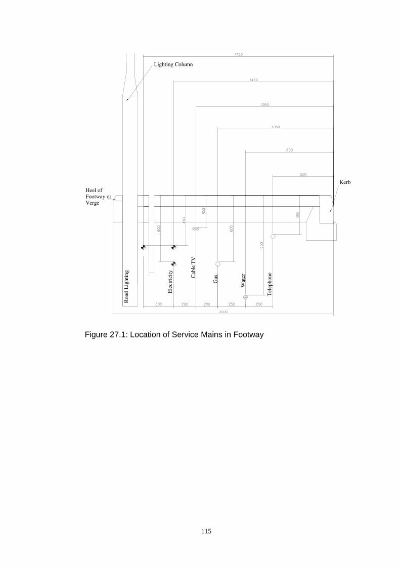
115
Figure 27.1: Location of Service Mains in Footway
116
28. Additional Design Considerations
28.1. Headroom
The minimum headroom for any structure other than a footbridge must be in
accordance with TD 27/05 when spanning a PRIMARY or DISTRICT
DISTRIBUTOR ROAD and 5.1 metres for all other roads, including those
through pends. The minimum headroom for footbridges must be in accordance
with TD 27/05 in all cases. Appendages to buildings (i.e. sunblinds, projecting
signs, etc) should be fixed at least 2.4 metres above adjacent footways, footpaths
or verges.
28.2. Disabled Persons
It is a statutory requirement to have regard to the needs of disabled people in
designing any building to which the public have access. This will include the
provision of suitable access routes for wheelchairs and the marking out of parking
bays for use by disabled drivers (Section 26.8) close to pedestrian entrances.
28.3. Bus Services
In planning major new developments, the need to provide or augment local bus
services will have an effect on road layout, widths, corner radii and pedestrian
access arrangements. For phased development, consideration should be given to
encouraging access by bus services at an early stage, for the convenience of the
first residents (see also Section 3.2).
28.4. Bus Stops
Bus routes, in order to be practical, must be reasonably fast and direct and connect
the centroids of the residential, business and shopping areas which they serve.
Services will generally be based on DISTRICT and LOCAL DISTRIBUTOR
ROADS although to achieve the desired penetration it may be necessary to use
access roads (suitably widened if required). Ideally bus penetration should be
such that no house or workplace is more than 400 metres from the nearest bus stop
where these are spaced at two or three per kilometre.
Bus stops will require to be provided with raised height kerbs, to improve the
accessibility to the buses. The standard layout for raised height kerbs is shown on
Figure 28.2.
Where bus shelters are to be provided, these should be sited so as not to obstruct
vehicle sight lines or footways. Bus shelters must be of a style approved by the
Roads Development Engineer.
28.5. Road Widths for Bus Routes
The minimum carriageway width for two-way operation of buses in new
developments should be 6.0 metres and bus bays may be required.
117
28.6. Traffic Management
The layout of a development may be influenced by existing or proposed traffic
management measures and the Roads Development Engineer should be consulted
about these at an early stage. Where traffic management measures are to be
introduced to facilitate a particular development, the developer will be required to
fund these measures, including any costs associated with the promotion of the
required traffic orders.
28.7. Fire Fighting
The width of roads and reinforced emergency vehicle paths and their proximity to
buildings is detailed in Section 2.12 of the Building (Scotland) Regulations
Technical Handbooks.
28.8. Refuse Collection
Developers should consult with Waste Management on the proposed refuse
collection arrangements for the development and take account of requirements for
positioning of refuse and recycling containers for collection in designing
pedestrian and vehicular routes within the site.
28.9. Traffic Noise
Traffic noise from the following sources should be taken into account:
(a) Existing roads
(b) New roads being constructed as part of the proposed development;
(c) Alterations to the road network to accommodate the proposed
development;
Where existing roads are incorporated into a new housing development care
should be taken to ensure that traffic noise levels do not exceed the specified level
contained in the Noise Insulation (Scotland) Regulations 1975.
The developer should also take account of noise generated during the construction
phase of the works and ensure that noise levels are maintained within acceptable
limits. The Local Planning Authority should be consulted at any early stage to
ensure that their requirements are met.
28.10. Clearances
A minimum 2.0 metres clearance is required at the ends of hammerheads etc.
where no footway is provided or adjacent to any walls or obstructions.
A minimum 0.6 metres clearance should be provided to all street furniture
Particular requirements for clearance apply to roundabout design (Section 18)

118
28.11. Safety Fences/Barriers
Developers are reminded of their responsibility to ensure that the design of road
layout promotes safety. To that end the requirements of TD19/06 of DMRB
should be taken into account in the design of any new development.
Safety barriers should be provided where required on single and dual carriageway
roads with a speed limit in excess of 50mph in accordance with the requirements
of TD 19/06. Safety Barriers will be required:-
a) On embankments 6 metres or more in height
b) On other embankments where there is a road, railway, water hazard
or other feature (e.g. a subway entrance) at or near the foot of the slope
c) On the outside only of curves less than 850 metres radius on
embankments between 3 and 6 metres in height
d) At obstructions including bridge piers or abutments, posts of large
signs and sign gantry legs and trees
e) At substantial obstructions such as retaining walls or steep sided (1
in 2 or steeper) rock face cuttings or earth bunds (1 in 1 or steeper) closer
than 4.5 metres to the edge of the running carriageway
f) At noise barriers or screens closer than 4.5 metres to the edge of
the running carriageway
Safety barriers will also be required on dual carriageways that meet the following
criteria:
a) Motorways with central reserve up to 10 metres wide
b) Dual two and three lane all purpose roads where the 24 hour
AADT flow is expected to be greater than 30,000 vehicles in the year of
opening
c) At obstructions including bridge piers, sign gantry legs and trees
d) Where there are lighting columns
e) Where the difference in carriageway inner channel levels exceeds
1.0 metres and the slope across the central reserve exceeds 25%; the safety
fence shall be sited at the top of the slope, but where the difference in
carriageway inner channel levels exceeds 0.5 metres and the slope across
the central reserve exceeds 15%, a case, including a forecast of costs and
benefits, shall be submitted to the Local Roads Authority for approval
f) Roads in urban areas with a 40 or 50mph speed limit without
central lighting columns where the central reserve is less than 1.75m wide
and adequate clearance between the face of the safety fence and the edge
of the carriageway can be obtained.
For roads with a speed limit less than 50mph, guidance on this matter can be
sought from the Roads Development Engineer.

119
28.12. Traffic Signs and Road Markings
The Developer shall be required to install, at his own expense, the necessary
traffic signs and associated road marking as required under the terms of the
current version of the Traffic Signs Regulations and General Directions.
Further reference should be made to Section 33 of this guide.
28.13. Street Name Plates
Street name plates will be required at all road junctions. These items are essential
to allow emergency services to navigate around new housing developments and
are potentially lifesaving features.
As such the following criteria for the number of signs required at each style of
junction is outlined below:
T – Junction
At both radii of the minor road for vehicles turning into the minor road.
Opposite the minor road junction for vehicles exiting the minor road. This is only
to be provided if the main road is a LOCAL DISTRIBUTOR or above.
T – Junction off a Cul-de-sac
As traffic will be predominately approaching the minor road from one direction
then only one street name plate is required on the minor road. This should be
placed on the radii of the minor road facing the oncoming traffic.
Figure 28.1 shows a typical street name plate layout.
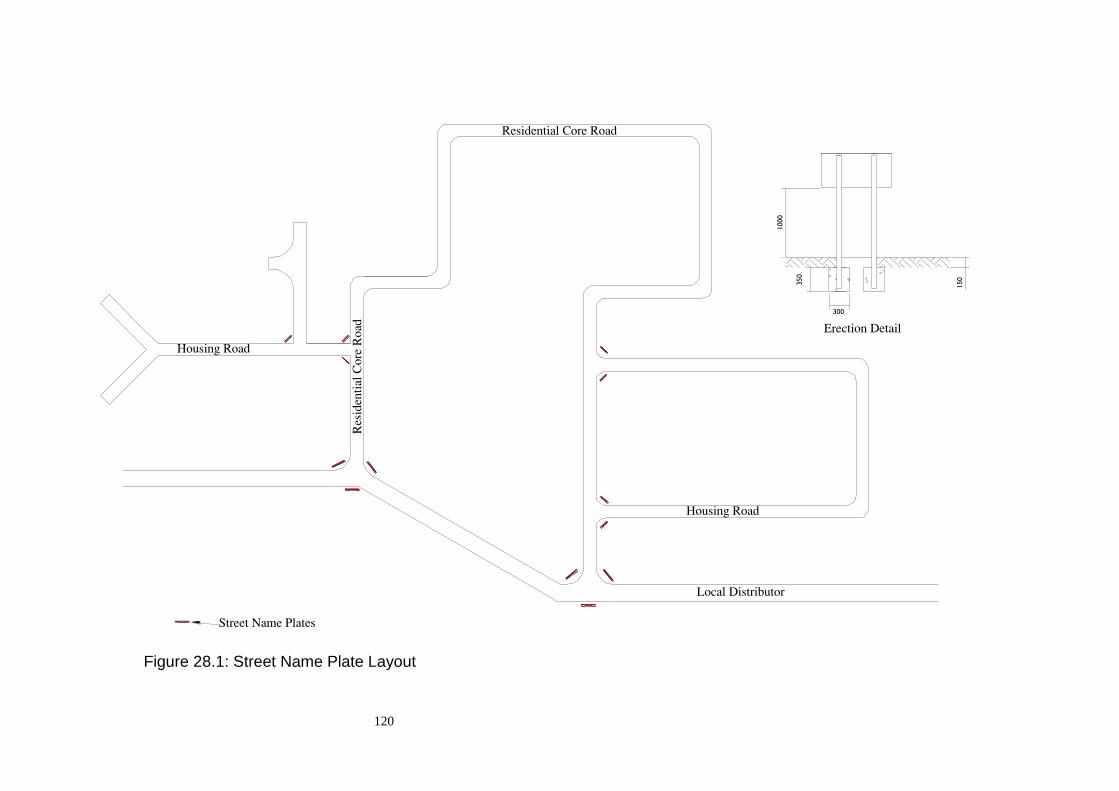
120
Figure 28.1: Street Name Plate Layout
350
300
1000
150

121
Figure 28.2: Bus Stop Kerb Detail
435
150
314
314
435
150
200
225
690
160
10001000
435
314
435
314
300
314
300
300
1000
300
314

122
Part 3 CONSTRUCTION DETAILS

123
29. Geotechnical Considerations
29.1. Introduction
The extent of the ground investigation requirements and the associated
documentation will be dictated by the nature of the proposed development and the
historical usage of the site.
29.2. Supporting Technical Documentation
All ground investigation reports shall comply with BS 5930:1999+A2:2010 Code
of Practice for Site Investigation. The Factual Ground Investigation Report
should include the following minimum information:
a) Exploratory borehole/trial pit logs
b) Laboratory test data relevant to the proposed form of road
construction
c) Location plan of the site at 1/2500 showing the proposed road
network and borehole/trial pit locations
The spacing of the boreholes/trial pits will depend upon the nature of the ground
conditions and the proposed development. Sufficient locations should be chosen
to ensure that the condition of the site can be fully identified.
Where there are existing slopes adjacent to the proposed development that have
the potential for failure which could impact on the proposed development, either
in respect of the built infrastructure or of the users, the ground investigation shall
include such slopes.
Full consideration should be given to the historic usage of the site and possible
contamination. For further information reference should be made to BS
10175:2011+A1:2013 Investigation of Potentially Contaminated Sites – Code of
Practice.
29.3. California Bearing Ratio (CBR)
The CBR value of the soil shall be determined by the laboratory CBR test in
accordance with BS 1377: Part 4: 1990 and test data shall be incorporated in the
Factual Ground Investigation Report.

124
30. Pavement Construction
30.1. Specification
The specification for the construction of road pavements and associated structures
is detailed in the specification section of this document. Clause numbers in the
following text refer to that specification.
30.2. Carriageway Construction
Carriageways for development roads up to Local Distributor or Industrial Access
standard shall be constructed in accordance with Table 30.1 subject to the
following qualifications:
(a) No frost-susceptible material shall be permitted within 450mm of
the final running surface. If the overall construction is less than 450mm, a
certificate of non-frost-susceptibility, for the sub-grade, is required;
(b) The formation CBR must not be less than 2%. Submission of a site
investigation report confirming the CBR value of the sub-grade is
required. For CBR values less than 2% see the current version of the
Design Manual for Roads and Bridges.
All new roads other than those above shall have the carriageway designed as a
flexible pavement in accordance with the following documents:
TRRL Report LR 1132, HD 26/06, and Volume 1 of the Manual of Contract
Documents for Highway Works.
30.3. Formation/Sub-Grade
Figure 30.1 gives depth of sub-base suitable for use when the sub-grade CBR is
greater than 2%. Where the CBR is less than 15% a capping layer of selected fill
or an increased depth of sub-base must be adopted. The diagram on Figure 30.1
should be used to determine allowable combinations of capping layer thickness
and sub base thickness. It should be noted that the overall depth of carriageway
construction must be at least 450mm. It may be the case that the minimum sub-
base depth indicated in Figure 30.1 will have to be increased to achieve the
450mm depth.
30.4. Sub-Grade Drainage
It is important to provide efficient permanent drainage of the sub-grade and any
other permeable layer of road. The water table should be prevented from rising to
within 0.6 metre of the formation level. This requirement is additional to those for
surface water drainage detailed in Section 31.
30.5. Camber, Crossfall and Gradients
Carriageways should be cambered with a fall of 2.5 per cent from the centreline to
the channel except on curves where, to eliminate adverse camber, a crossfall of
2.5 per cent between channels should be provided. For roads surfaced with block

125
paving a 2.5 per cent crossfall shall be provided throughout. At a junction, the
carriageway of the minor road should be graded into the channel of the minor
road.
Footways and footpaths shall be constructed with a crossfall of 2.5 per cent, and
lay-bys shall be provided with a 2.5 per cent crossfall towards the road channel.
Channel gradients shall not be flatter than 0.8 per cent (1 in 125). See typical
layout in Figure 30.5.
30.6. Recycled Materials
The use of recycled materials in carriageway and footway construction will be
favourably considered in the following situations, at the discretion of the Roads
Development Engineer.
(1) Recycled bituminous materials on the Base Layer of roads
designed to carry up to 1.5 MSA.
(2) Recycled granular material in sub-base layers and capping layers if
in accordance with the appropriate specifications for grading and frost
susceptibility.
(3) Both recycled bituminous and granular materials will be allowed in
footway, footpath and cycletrack construction.
30.7. Two Stage Construction
Where, owing to the continued use of the road by construction traffic, it is
necessary (in order to avoid damage to the Surface Course) to adopt a two - stage
construction, a minimum Binder Course thickness of 55mm shall be provided.
Consideration should be given to the condition of the temporary surface before the
final course is laid. This applies particularly in large projects where the
construction period may be long and the Surface Course not laid before the winter
work period. Any settlement, which may occur in the Binder Course, should be
taken up with Regulating Course before the laying of the Surface Course, and
early reinstatement of openings or failed areas is essential. Before the Regulating
Course or Surface Course is laid, the top surface of the Binder Course must be
well cleaned and tack coat applied at the rate of 0.6 litres per square metre. If the
developer wishes to omit the kerbs during the 1st stage construction an ‘L’ shaped
kerb foundation (Figure 25.2) shall be used.
30.8. Tie in to Existing Carriageway
It is important that special attention is paid to the area where new construction
ties-in to the existing road network. This zone is prone to failure due to poor
compaction and the ingress of water. In light of this, all tie-ins should be
constructed in accordance with the details shown in Figures 30.2 and 30.3.

126
Table 30.1 - Carriageway Construction
Type Sub Base Base Binder Course Surface Course
Local Distributor Road
(4 MSA)
See Figure 30.1(210mm
Min) Cl 803
140mm AC 32 dense
base 100/150
(i) BS EN 13108-1
55mm AC 20 HDM bin
des 40/60
(i) BS EN 13108-1
45mm HRA 30/14F surf 40/60 des
(i) Reference: EN13108-4
(ii) Coated Chippings: Nominal size -
20mm in accordance with Clause 915 and
shall
conform to BS EN13108-4, taking into
account CL915 and the detailed
requirements in
BSI PD 6691 Annex C Clause C.2.8.2.
(a) PSV Category: Strategic and
Distributor Roads: PSV62 ( _ 62 )
(b) Residential Roads: PSV50 ( _ 50 )
(c) AAV Category: AAV10 ( _ 10 )
(iii) Minimum Air temperature for laying
surface course 0º C
(iv) Minimum delivery temperature 155º C
(v) Wind speed ( maximum at any air
temperature) 40km/h (at 2m height)
Industrial Access Road
(4 MSA)
See Figure 30.1 (210mm
Min) Cl 803
Core Road (2 MSA) See Figure 30.1 (230mm
Min) Cl 803
120mm AC 32 dense
base 100/150
(i) BS EN 13108-1
Housing Road
(0.7 MSA) See Figure 30.1 (270mm
Min) Cl 803
80mm AC 32 dense
base 100/150
(i) BS EN 13108-1
Home Zone
(0.5 MSA)
Consult Roads
Development Engineer
Consult Roads
Development
Engineer
Consult Roads
Development Engineer
Consult Roads Development Engineer
127
30.9. Concrete Block Carriageway Paving
Block pavements may be acceptable for use in HOME ZONES.
Paving blocks shall be 100mm x 200mm x 80mm in either red, buff, or charcoal.
Other colours are to be specifically agreed with the Roads Development Engineer.
They will be laid to a Herringbone pattern with a stretcher course adjacent to
kerbs, manholes and gullies. Cuttings, smaller than ¼ block will not be permitted.
Gradients flatter than 1.25% are not recommended.
It is particularly important that the design of block pavements incorporates
adequate provision for the drainage of unbound sub-base and sub-grade materials
(Section 30.4) particularly where there are low longitudinal gradient. Where a
55mm road base is incorporated to provide a temporary running surface adequate
drainage of the bedding layer must be provided.
The method of construction and materials should be in accordance with BS
EN1338:2003 Concrete Paving Blocks. Requirements and test methods and BS
7533-3:2005+A1:2009 Code of Practice for laying precast concrete paving blocks
and clay pavers for flexible pavements. Reference should also be made to
“Concrete block paving: guide to the properties, design, construction,
reinstatement and maintenance of concrete block pavements Edition 2” published
by Interpave.
30.10. Footway, Footpath and Cycletrack Construction
Footways, footpaths and cycletracks shall be constructed in accordance with Table
30.2 and as detailed in Figures 30.5 & 25.1 respectively unless an alternative
design is agreed with the Roads Development Engineer.
It should be noted that under normal circumstances cycle tracks or shared
pedestrian/cyclist facilities will only be permitted in flexible construction.
No frost-susceptible material shall be permitted within 450mm of the finished
surface. If the overall construction is less than 450mm, a certificate of non-frost-
susceptibility for the sub-grade is required
30.11. Flexible Construction
Flexible footways, footpaths or cycletracks shall be constructed in accordance
with Appendix 11/1-B of the Specification. It should be noted that Design Group
A is not suitable for areas where services still have to be installed.
30.12. Concrete Slab Paving
Concrete Slab paved footways or footpaths shall be constructed in accordance
with Appendix 11/1-A of the Specification. It should be noted that Concrete Slab
paving is not suitable for the construction of cycletracks or shared pedestrian
/cyclist facilities.

128
30.13. Small Element Slab Paving
Concrete Small Element Slab paved footways and footpaths shall be constructed
in accordance with Appendix 11/1 – A of the Specification. It should be noted
that Concrete Small Element Slab paving is not suitable for the construction of
cycletracks or shared pedestrian/cyclist facilities.
30.14. Block Paving
Concrete Block paved footways or footpaths shall be constructed in accordance
with Appendix 11/1 – D of the Specification. It should be noted that Concrete
Block paving is not suitable for the construction of cycletracks or shared
pedestrian/cyclist facilities.
30.15. Insitu Concrete Paving
Insitu Concrete paving shall be constructed in accordance with Appendix 11/1 – C
of the Specification. It should be noted that Insitu Concrete paving will only be
acceptable in areas where there is a specific Planning requirement for the use of
this material.
30.16. Granolithic Concrete Paving
Granolithic Concrete paving shall be constructed in accordance with Appendix
11/1-E of the Specification. It should be noted that Granolithic Concrete paving
will only be acceptable in areas where there is a specific Planning requirement for
the use of this material.
30.17. Granite Slab Paving
Granite Slab paving shall be constructed in accordance with Appendix 11/1-G of
the Specification. It should be noted that Granite Slab paving will only be
acceptable in areas where there is a specific Planning requirement for the use of
this material.
30.18. Kerbs and Edging
All carriageways, footways, footpaths and cycletracks shall be provided with a
precast concrete kerb or edging as detailed in Figures 25.1, 25.2 and 30.5.
On conventional roads, with traditional drainage systems, kerbs shall be set
100mm above finished carriageway channel level, except at pedestrian and
vehicular crossing’s where this dimension is reduced to 6mm and 20mm max
respectively.
Edging at the back of footways should have an upstand of 50mm, whereas on
footpaths and cycletracks it should be set flush with the walking/running surface.

129
Table 30.2 - Footway and Footpath Construction
Type Sub-Base Binder Course Surface Course
Flexible
Construction
100mm Type 1
Unbound mixture 40mm AC 14 open
surf 160/220 (BS
EN 13108-1) or
AC close surf
160/220 (BS EN
13108-1)
20mm AC 6 dense surf
100/150 (BS EN 13108-
1)
or 30mm HRA 15/10F
surf 40/60 des (BS EN
13108-4). After laying 6-
10mm coloured stone
chippings or other
approved shall be rolled
into the surface at the
rate 0.8 kg/sq.m.
Slabbed
Construction
Small Element
Slabs
100mm Type 1
Unbound mixture
150mm Type 1
Unbound mixture
25mm bed 6:1
sand/cement
mixture
25mm bed medium
course sand
Hydraulically pressed
concrete
slabs
900 x 600 x 65mm and
600 x 600 x 65mm
(cl 1104S)
Hydraulically pressed
slabs
400 x 400 x 60mm
Block Paving
(Pedestrian
Traffic only)
100mm Type 1
Unbound mixture 50mm sharp sand
bedding layer
100mm x 200mm x
60mm
rectangular paving
blocks (cl 1107)
Insitu Concrete
Construction*
75mm Type 1
Unbound mixture
100mm insitu concrete
slab
Granolithic
Concrete
Construction*
75mm Type 1
Unbound mixture
80mm insitu
concrete slab
20mm insitu granolithic
concrete
Granite Sett
Construction*
See BS 7533 Parts 7 & 10
Granite Slab
Construction*
See BS 7533 Parts 4, 8 & 12
* These footway construction types are only suitable where required by specific
planning requirements.
130
30.19. Minor Accesses
Where a vehicular access other than to individual dwellings is taken over a
footway, a crossing, as detailed in Figure 25.3 should be provided with
construction depths to the specification for a Housing Road carriageway.
30.20. Residential Accesses
Vehicular access crossings of the footway to individual dwellings should comply
with Figure 25.3 and be constructed to the footway specification for a Housing
Road carriageway.
30.21. Pedestrian Crossings
Figure 25.4 details the requirement for dropped kerbs where pedestrian routes
cross the carriageway from adjacent footways (e.g. at T-junction and controlled
crossings).
On all routes of Distributor Road classification, or higher, tactile paving must be
incorporated into the design of the crossing points where the crossings is
perpendicular to the main pedestrian flow, i.e. a pedestrian refuge.
Tactile Paving slabs should be installed in accordance with the recommendations
in the Department for Transport’s “Guidance on the use of tactile paving
surfaces”.
Pedestrian crossings in a road with an adjacent grass verge shall comply with
Figure 25.3(b) except that the number of dropped kerbs should be two and they
should be set a maximum of 6mm above the surface course.
30.22. Emergency Accesses
Emergency accesses must be designed with sufficient bearing capacity to carry
commercial vehicle loadings. Further advice can be obtained from the Roads
Development Engineer.
Construction to Housing Road standard will be acceptable for this purpose.
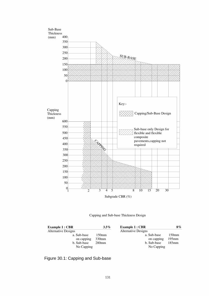
131
Figure 30.1: Capping and Sub-base
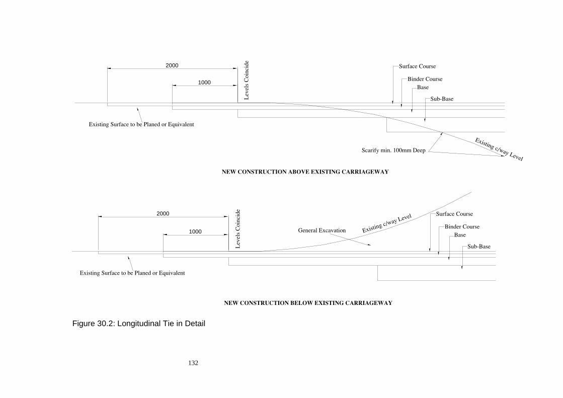
132
Figure 30.2: Longitudinal Tie in Detail
2000
1000
2000
1000

133
Figure 30.3: Carriageway Widening Tie in Detail

134
Figure 30.4: Buff Tactile Paving
600
600
600
Crossing Type 1
Crossing Type 2
Crossing Type 3
600
600
900
900
900
900
900
900
225 225
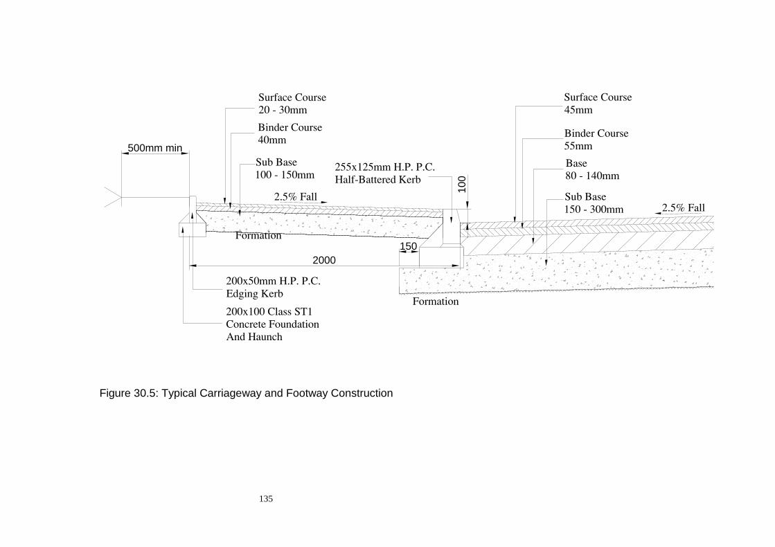
135
Figure 30.5: Typical Carriageway and Footway Construction
500mm min
100
2000
150

136
31. Road Drainage
31.1. Best Management Practices
Any built up area will require to be drained to remove excess surface water.
Traditionally this has been done using underground pipe systems designed for the
quantity of runoff, to prevent flooding locally. As the pipe system removed runoff
from the area more quickly than natural flow it has the potential to cause problems
in other areas of the catchment.
In recent years issues relating to water quality have become more important, due
to pollutants being washed into watercourses and groundwater. Traditional
drainage systems cannot easily deal with this particular issue and may actually add
to the problems.
Continuing to drain built up areas in this manner is no longer a sustainable long-
term option. Developers are therefore required to address surface water runoff by
the incorporation of Sustainable Urban Drainage Systems (SUDS) into their
overall design.
31.2. Sustainable Urban Drainage Systems
Sustainable Urban Drainage Systems (SUDS) are made up of one or more
structures built to manage surface water runoff. They are used in conjunction with
good management of the site, to prevent pollution. There are four general
methods of control:
1. Filter strips and swales
2. Filter drains and permeable surfaces
3. Infiltration devices
4. Basins and ponds.
These devices should be placed as close as possible to where the rainwater falls to
provide attenuation for the runoff. The above measures also provide treatment for
the surface water, in varying degrees, using the natural processes of
sedimentation, filtration, adsorption, and biological degradation.
Further guidance on the design of SUDS can be obtained from The SuDS Manual,
published by CIRIA (C697) and SUDS for Roads published by SCOTS.
31.3. Drainage Impact Assessment
For the majority of developments a Drainage Impact Assessment will be required.
This document is usually included with the initial Planning Application, either
Outline or Detailed. The DIA should be site specific and deal with all drainage
aspects relating to the site and must demonstrate that the appropriate SUDS
measures have been employed.

137
Further guidance on this matter can be found in “Drainage Impact Assessments –
Guidance for Developers” published by the North East Scotland Flooding
Advisory Group.
31.4. Appropriate Level of Treatment
Each site will have to be considered on an individual basis to determine the most
effective combination of SUDS measures. However in general terms the runoff
from every Residential Development should be subjected to one level of treatment
before it is discharged.
In general terms Non Residential sites will require 2 levels of treatment and
Industrial sites will require 3 levels of treatment.
Early contact with SEPA, Scottish Water and the Local Roads Authority is
essential to ensure that these requirements are addressed early in the design stage.
31.5. Road Drainage
To accommodate the requirements of SUDS road drainage will need to
undergo at least one level of filtration before it is discharged into the public
sewer or watercourse.
In addition, the drainage system will be required to have a degree of storage
to enable it to provide an acceptable level of attenuation in flood conditions
Further guidance on the design of SUDS can be obtained from The SUDS
Manual, published by CIRIA (C697) and SUDS for Roads published by SCOTS).
31.6. Footpath /Cycletrack Drainage
To remove gully-clearing difficulties, remote footpaths should be constructed with
flush edging and adjacent land drainage provided as detailed in Figure 25.1. Only
in exceptional circumstances, as agreed with the Roads Development Engineer,
should direct drainage into gullies be considered as an alternative.
31.7. Design of Piped Road Drainage
Piped Road drainage design should be in accordance with the current edition of
the Design Manual for Roads and Bridges subject to the qualification that the
minimum pipe diameter permitted will be 150mm. Land drainage or other
appropriate measures must be taken to prevent water flowing on to the road
from adjacent properties.
31.8. Gully Spacing
Table 31.1 details the acceptable channel distance between gullies for a road
comprising of carriageway and two 2 metre wide footways, or a road and two 3
metre wide footway/cycletracks for the 7.3m wide road. The gully spacing will be

138
based on the criteria laid out in the Design Manual for Roads and Bridges,
Volume 4, Section 2, Part 3, HA 102/00.
The following assumptions will be made in any gully spacing design:
Mannings ‘n’ 0.017
Storm Intensity 50mm/h
Flow Width 0.75m
Maintenance Factor 0.8 (0.7 for sag curves)
Min Grating Grade T
The following special requirements will also apply:
a) Terminal gullies must have an efficiency rating of at least 95%, to
prevent excessive flow past the final grating.
b) At sag points twin gullies are to be used. The efficiency of both
these gullies must be at least 95%, to prevent excessive flow past the
grating.
The spacing may require to be altered according to the road layout (e.g. at
junctions) and special measures will be required where the grade is necessarily
flatter than 0.8 per cent (sags, crests, etc). Advice on these matters should be
sought from the Roads Development Engineer who should be consulted at an
early stage by any developer wishing to carry out a full drainage design.
Irrespective of design spacing, a gully shall be positioned:
a) Just upstream of the tangent point at road junctions;
b) Short of the point where adverse camber is removed when applying
super-elevation;
c) At any local low point;
d) At a maximum spacing of 50 metres;
e) To ensure that the maximum area draining to any one gully does
not exceed 180 sq.m.
31.9. Lay-by Drainage
Lay-bys shall be drained by means of gullies located along the road channel; it
should not, therefore, be necessary to provide gullies at the rear of lay-bys/bus
bays.

139
Table 31.1 - Gully Spacing for Carriageways
Gradient Flatter than
0.8% (1/125)*
0.8%
1/125
1.0%
1/100
1.25
1/80
1.66
1/60
2.5
1/40
5.0
1/20
5.55
1/18
Cross
Section
C/W
Width
Gully Spacing (metres)
2.5%
(1/40)
Camber
5.5m
6.0m
7.3m
15
14
11
18
17
13
19.5
18.5
14
21.5
20.5
15.5
24.5
23
17.5
29
27.5
20.5
37.5
35.5
27
39
37
28
2.5%
(1/40)
Crossfall
5.5m
6.0m
7.3m
7.5
7
5.5
9
8.5
6.5
10
9
7
11
10
7.5
12
12
8.5
14
14
10
19
18
13
20
19
14
* Gradient flatter than 0.8% applicable to crests and sags only
31.10. Gullies
Road gullies must be constructed in accordance with Clause 508 of the
specification and fitted with external traps as shown on Figure 31.1. Gully pots
should be either 450mm inside diameter (I.D.) precast concrete or 450/510mm
I.D. insitu concrete with plastic former. Gully gratings and frames must be Class
D400 complying with BS EN 124 and be of a size compatible with the gully pot.
Gully frame is to be 100mm deep. Gully grating is to be set 6mm below the road
surface.
Note: Bars of gratings to be at right angles to kerb line, and where applicable
hinge side to be facing oncoming traffic.
31.11. Connections
Where gullies are to be connected to a surface water drain it shall be by 150mm
diameter jointed fire-clay or plastic pipes, which will be surrounded with 150mm
of Class ST1 concrete where the cover to the earthworks outline is less than 0.9
metres.
Connections should be constructed in accordance with Clause 508 of the
Specification.
Where Land drains are to be connected to the surface water drain it must be via a
silt trap.

140
31.12. Down Pipes
In redevelopment areas existing down pipes, which may have previously
discharged over the footway or through a channel, must be connected either
directly into a gully pot or its connection with 100mm jointed PVC or fire-clay
pipes. Permission will be required from Scottish Water and SEPA for this form of
surface water treatment.
31.13. Chambers
Chambers should be constructed as detailed in Volume 3 of the Manual of
Contract Documents for Highway Works and must be to the satisfaction of the
adopting authority. All covers shall incorporate a permanent non-rock feature
either triangular point suspension of machined faces.
All covers should be hinged and have a minimum clear square opening of 600mm.
All manhole covers shall open such that an operative will have an unobscured
view of the oncoming traffic when entering and leaving the manhole.
Where circumstances do not allow normal compaction to be carried out between
manholes etc. Class ST1 concrete will be required to be placed as directed by the
Roads Development Engineer.
31.14. Pipework
All pipework for road drainage must be designed in accordance with Volume 4,
Section 2, Part 5, HA 40/01 of the Design Manual for Roads and Bridges and
constructed in accordance with the Manual of Contract Documents for Highway
Works.
31.15. Outfall Connection
The connection of road drainage systems to the public sewer network must be
undertaken only with the authority of Scottish Water (Section 27). When
connecting to an existing watercourse, approval must be sought from the Scottish
Environmental Protection Agency. Permission under Section 109 of the New
Roads and Street Works Act will be required where apparatus is to be installed in
the public road.

141
Figure 31.1: Typical Road Gully
Grating and frame to comply with
BE EN 124 Class D400 (Double Triangular)
set 6mm below road surface and to fall.
450/510 dia.
750
min
.
150
2 courses of brick to Clause 2406
150mm ST4 concrete surround.
(ST1 concrete where concrete
pots are used.)
Gully pot of precast concrete
or plastic to Clause 508.
(Plastic former indicated.)
ST1 concrete haunch
Frame to be bedded on 10-20mm
of Class 1 Cement mortar.

142
32. Road Lighting
32.1. Application for Consent
It is important that Developers consult the Roads Development Engineer at an
early stage, as adjustments to the lighting design may be necessary to meet
Construction Consent requirements. In addition the Roads Development Engineer
will give guidance on the type of lantern and lamp that may be appropriate for the
development.
32.2. Information to be Supplied
Applications for Construction Consent should be accompanied by three paper
copies of detailed drawings showing the following:
Location and type of lighting columns and lanterns, wall mounted units (if
applicable), feeder pillars, underground cables (including size and type and
sections to be ducted) and road crossing ducts.
Further guidance on this matter can be found in Section 4 of this guide.
32.3. Inspections
The Developer is reminded of his obligation to give the Roads Development
Engineer a minimum of 48 hours notice of the following operations:
Setting out of road lighting plant and positions, backfilling of trenches and
painting of lighting columns.
32.4. Specification
The specification for the provision and installation of road lighting shall be the
current version of the Specification for Highway Works, with amendments and
additions as detailed in Appendix 13 of the Specification.
32.5. Design
Lighting shall be designed to comply with the requirements of BS 5489.
Where a speed limit of 60kph (40mph) or higher is to apply to a road the
Developer should seek guidance from The Roads Development Engineer on the
standard of lighting required. The road lighting design should be agreed with the
Roads Development Engineer prior to application being made.
LED units shall be used for all street lighting and sign lights. All
specifications shall be agreed with the Roads Development Engineer prior to
approval being granted.
All street lighting installations should be capable of various levels of dimming.
The exact requirements in relation to lighting levels and controllable hours will be

143
assessed on each individual application and will be dependent on site location. All
specifications shall be agreed with the Street Lighting Engineer prior to approvals
being granted.
All street lighting cable installations should be ducted.
Lighting design calculations showing the levels achieved from the proposed
layout and equipment must accompany the application.
32.6. Location of Apparatus
While the approximate location of all lighting apparatus should be indicated on
the drawings, the exact position must be determined on site and approved by the
Roads Development Engineer. Lighting columns should normally be located at
the rear of the footway or where there is a grass verge adjacent to the carriageway,
at the heel of this verge. Underground lighting cables should be correspondingly
located within 0.3 metre of the rear of the footway or verge (Figure 27.1) and the
Developer must ensure that no other service is allowed to encroach within this
area. The routes of any surface cables must be agreed with the Roads
Development Engineer prior to their installation.
32.7. Decorative Equipment
Decorative lighting equipment usually has significant maintenance cost
implications and for this reason it is limited to high amenity and conservation
areas. Consultation with the Planning Authority may be necessary and the
approval of the Roads Development Engineer must be obtained.
32.8. Column Location
The minimum clearances from the edge of the carriageway to the lighting column
shall be as detailed in BS 5489.
32.9. Road Opening Permit
The Developer must obtain the necessary permission under Section 109 of the
New Roads and Streetworks Act where apparatus is to be installed in the public
road.
32.10. Existing Services
The Developer is responsible for contacting the Statutory Undertakers regarding
the position of any existing underground plant.
32.11. Maintenance
Only roads which have been constructed in accordance with a Construction
Consent approval will be considered for public lighting which would be adopted
for maintenance by the Local Roads Authority.

144
The maintenance of all lighting shall be the responsibility of the developer until
such time as the road and lighting are formally adopted by the Local Roads
Authority. The Roads Development Engineer will require written confirmation
that an agreement has been reached with a suitable lighting contractor to ensure
that the lighting is maintained to the required standard. This may be a service
which the Local Roads Authority can supply, on a fully rechargeable basis.
32.12. Electricity Supply
The Developer will require to make application to the relevant electricity supplier
for a connection from an unmetered supply to the street lighting feeder pillar
where required.
Where the supply is to be taken from existing lighting installations belonging to
the Local Roads Authority, the final connection must be made by the Local Roads
Authority’s contractor on a rechargeable basis. Application must be made using
Form CC8 giving at least 6 weeks notice.
32.13. Electricity Consumption
The Developer will require to make arrangements with the relevant power
supplier in relation to payment for electricity consumed by the street lighting until
such time as the road and lighting are formally adopted by the Local Roads
Authority.
The Roads Development Engineer will require written confirmation that such an
agreement is in place.
32.14. Bond
In the event of a developer failing to provide operational street lighting adjacent to
occupied housing, he will be given 28 days notice to make such provision. Failure
to comply with this requirement within the period of notice will result in the Local
Roads Authority arranging for procedures to be initiated to call in the Bond to
fund the installation of the required street lighting apparatus.
Similarly, failure to rectify a fault resulting in malfunction of the street lights,
within a period of 5 days will cause the Local Roads Authority to effect a repair
with the costs being invoiced to the Developer.

145
33. Traffic Signs and Road Markings
33.1. Responsibility of the Developer
The Developer will be required to provide appropriate traffic signs and road
markings as directed by the Roads Development Engineer. The full cost of this
provision will be borne by the Developer.
33.2. Design and Siting of Traffic Signs
All traffic signs will be designed in accordance with the current version of the
Traffic Signs Regulations and General Directions, the Traffic Signs Manual, and
BS EN12899-1:2007 – Fixed Vertical Road Traffic Signs.
Traffic sign poles should be designed to accommodate a wind pressure of 15
millibars (156 kg/sq.m.)
The materials used for the construction of the sign faces and the poles will meet
the relevant standards as set out in Appendix 12 of the Specification.
33.3. Road Markings
Where any road joins a Distributor, or higher, classified road junction marking
and signage shown on Figure 18.4 will be required.
If the junction is with a CORE ROAD the junction markings shown in Figure 18.5
will be required. In certain circumstances this requirement may be relaxed at the
discretion of the Roads Development Engineer.
In general no junction markings will be required when both roads are HOUSING
ROADS classification or less.
These marking will be in accordance the current version of the Traffic Signs
Regulations and General Directions.
The road markings material will comply with BS EN 1436 and the requirements
of Appendix 12 of the Specification.
33.4. Street Name Plates
Street name plates will be required at all road junctions. These items are essential
to allow emergency services to navigate around new housing developments and
are potentially lifesaving features.
As such the following criteria for the number of signs required at each style of
junction is outlined below:

146
T – Junction
At both radii of the minor road for vehicles turning into the minor road
Opposite the minor road junction for vehicles exiting the minor road. This is only
to be provided if the main road is a Local Distributor or above.
T – Junction off a Cul-de-sac
As traffic will be predominately approaching the minor road from one direction
then only one street name plate is required on the minor road. This should be
placed on the radii of the minor road facing the oncoming traffic.
Figure 28.1 shows a typical street name plate layout and erection details.
33.5. Alterations to Existing Signage
In some cases as a result of the development alterations will be required to
existing road markings and signs on the public road. Any such requirements will
be notified to the Developer by the Roads Development Engineer at the Consent
approval stage.
The Developer will be responsible for carrying out the required alterations and
will be responsible for meeting the full cost of any such alterations.
147
34. Road Landscaping
34.1. Specification
The specification for road landscaping is detailed in Appendices 6/8 and 6/9 of the
Specification.
34.2. Design
Any landscaping proposed for areas within the road boundaries should be
designed to minimise future maintenance requirements as determined by the
Roads Development Engineer.
34.3. Soft Verge
Soft verges shall be grassed in accordance with Appendix 6/8 of the specification
unless an alternative form of surfacing is authorised by the Roads Development
Engineer, in consultation with the Statutory Undertakers where appropriate.
There must be a permanent and continuous demarcation of the boundary between
the verge and adjoining private property (e.g. by a fence, wall or concrete edge
kerbing).
34.4. Topsoil
Topsoil shall be spread to a uniform thickness on all areas to be seeded as
specified in Appendix 6/8 of the specification. Prior to soiling, the top 200mm of
existing ground should be broken up to facilitate drainage.
34.5. Grass Seed
Unless otherwise agreed by the Roads Development Engineer, grass seed should
comprise the mixture listed in Appendix 6/8 to the Specification. The Developer
will be responsible for resowing, in the following season, any area where the
seeding is not successful.
34.6. Hard Verges
The form of any hard landscaping should be agreed with the Roads Development
Engineer at an early stage in the design process.
Scottish Water may require "grasscrete" or similar to be provided in specific
locations.

148
35. Contact Names and Addresses
Banff / Buchan and Buchan
Principal Engineer (Roads Development) – David Naismith
Location – Cape House
21 Seafield Street
Banff
AB45 1ED
Telephone Number – 01261 813415 (Direct Dial)
01261 813200 (Switchboard)
Formartine and Garioch
Principal Engineer (Roads Development) – Graeme Steel
Location – Gordon House
Blackhall Road
Inverurie
AB51 3WA
Telephone Number – 01467 628087 (Direct Dial)
01467 620981 (Switchboard)
Kincardine / Mearns and Marr
Principal Engineer (Roads Development) – Alasdair Macdonald
Location - Carlton House
Arduthie Road
Stonehaven
AB39 2DQ
Telephone Number – 01569 768480 (Direct Dial)
01569 768455 (Switchboard)
Street Lighting
Street Lighting Officer – Keith Melvin
Location – Gordon House
Blackhall Road
Inverurie
AB51 3WA
Telephone Number – 01467 628014 (Direct Dial)
01467 620981 (Switchboard)

149
36. Bibliography
Title Publisher
Construction (Design and Management)
Regulations 2007
The Stationery Office
Designing For Deliveries Freight Transport
Association
DMRB – Design Manual For Roads and
Bridges
The Stationery Office
Good Practice Guide on 20mph Speed
Restrictions
Transport Scotland
Inclusive Mobility Department for Transport
Noise Insulation (Scotland) Regulations HMSO
Road Hump (Scotland) Regulations 1998 The Stationery Office
Road Humps and Traffic Calming
(Scotland) Amendment Regulations
The Stationery Office
Roads (Scotland) Act 1984 HMSO
Security for Private Roads Works (Scotland)
Regulations 1985
HMSO
The Security for Private Road Works
(Scotland) Amendment Regulations 1998
The Stationery Office
Technical Handbooks (Building Standards) The Scottish Government
The Home Zones (Scotland) (No.2)
Regulations
The Stationery Office
Traffic Signs Regulations and General
Standards
The Stationery Office
Transport (Scotland) Act 2001 The Stationery Office

150
37. Safety Audit Stages
Stage 1 (Preliminary Design – Order Publication Report Stage)
Contents Items
A1: General Departures From Standards
Cross Sections
Cross-sectional Variation
Drainage
Climatic Conditions
Landscaping
Public Utilities/Services Apparatus
Laybys
Access
Emergency Vehicles
Future Widening
Staging of Contracts
Adjacent Development
A2: Local Alignment Visibility
New/Existing Road Interface
Vertical Alignment
A3: Junctions Layout
Visibility
A4: Non motor vehicle provision Adjacent Land
Pedestrians/Cyclists
Equestrians
A5: Signs and Lighting Signs
Lighting
Poles/Columns
A6: Construction and Operation Buildability
Operation
Network Management

151
Stage 2 (Completion of Detailed Design – Works Commitment Stage)
1. The Audit Team should satisfy itself that all issues raised at Stage 1 have
been resolved. Items may require further consideration where significant design
changes have occurred.
2. If a Scheme has not been subject to a Stage 1 Audit, the items listed in lists
A1 to A6 should be considered together with the items listed below
Contents Items
B1: General
Departures of Standards
Drainage
Climatic Conditions
Landscaping
Public Utilities/Services Apparatus
Laybys
Access
Skid Resistance
Agriculture
Safety Fences
Adjacent Developments and Roads
B2: Local Alignment Visibility
New/Existing Road Interface
B3: Junctions Layout
Visibility
Signing
Lighting
Road Markings
T, X, Y-Junctions
All Roundabouts
Mini Roundabouts
Traffic Signals
B4: Non Motor Vehicle Provision Adjacent Land
Pedestrians
Cyclists
Equestrians
B5: Signs and Lighting ADS and Local Traffic Signs
Variable Message Signs
Other Traffic Signs
Lighting
Road Markings

152
Poles and Columns
B6: Construction and Operation Buildability
Operation
Network Management

153
Stage 3 (Substantial Completion)
1. The Audit Team should Consider whether the design has been properly
translated into the scheme as constructed and that no inherent safety defect has
been incorporated into the works.
2. Particular attention should be paid to design changes which have occurred
during construction
Contents Items
C1: General Departures from Standards
Drainage
Climatic Conditions
Landscaping
Public Utilities/Services
Apparatus
Access
Skid Resistance
Safety Fences
Adjacent Development
Bridge Parapets
C2: Local Alignment Visibility
New/Existing Road Interface
C3: Junctions Visibility
Road Markings
Roundabouts
Traffic Signals
T and Y Junctions
C4: No motor vehicle provision Adjacent Land
Pedestrians
Cyclists
Equestrians
C5: Roads Signs, Carriageway Markings and
Lighting
Signs
Variable Message Signs
Lighting
Carriageway Markings
C6: Operation Maintenance
Network Management

154
38. Accessible Design and Access Audits
38.1. Policy Statement
The Policy of Aberdeenshire Council, Infrastructure Services, Roads Service is to
comply with the requirements of the Equality Act and in particular to remove or
alter physical barriers that prevent disabled people gaining access to service, or to
provide the service in an alternative way, where reasonable.
38.2. Design Standards
“Inclusive Mobility – A Guide to Best Practice on Access to Pedestrian and
Transport Infrastructure” (Published by the Department for Transport in 2002) has
been adopted by Aberdeenshire Council, Infrastructure Services as the guidance
document for design to meet these requirements.
The design standards and principles included in the document shall be the
Desirable Standards for all designs and shall be those against which Access Audits
shall be carried out.
38.3. Departures from Desirable Standards
All reductions in the Desirable Standards shall be considered as a Departure from
Standard and each Departure shall be assessed to determine if it is “reasonable”.
The process of assessment shall be documented to demonstrate that it has taken
place between the Designer, Checker and Access Auditor.
The documentation in respect of Departures shall be submitted as part of the
Roads Construction Consent application.
38.4. Access Audits
The approach adopted for the assessment of designs to determine their compliance
with desirable design standards is similar to the established procedure for Safety
Auditing.
The approximately equivalent stages are as detailed below :-
Stage 1 Safety Audit - Preliminary Access Audit
Stage 2 Safety Audit - Design Access Audit
Designer’s Risk Assessment - Access Statement
Stage 3 Safety Audit - Post-Construction Access Audit

155
38.5. Access Auditor
Access Audits shall be carried out by a trained Access Auditor independent of the
design team for the project.
Access Auditors shall be registered with:-
The National Register of Access Consultants , 70 South Lambeth Road,
London, SW8 1RL, (www.nrac.org.uk)
Tel: 020 7735 7845, Fax: 020 7840 5811
either as Access Auditors or Access Consultants.
Where more than one stage of Access Auditing is required, the same Auditor
shall, where possible, carry out all of the stages.
38.6. Access Audit Procedure
A Design Access Audit shall be carried out for all projects and an Access
Statement submitted as detailed below.
For complex schemes it may be advantageous to carry out a Preliminary Access
Audit in order to identify any features requiring particular attention at an early
stage in the design process.
Post-construction Access Audits shall not generally be required unless
recommended by the Access Auditor in the Design Access Audit Report.
The Designer shall produce an Audit Brief, as detailed below, for each required
Access Audit stage.
For each audit the Access Auditor shall consider whether any additional items
require to be considered and add these to the checklist to form a scheme-specific
list.
38.7. Access Audit Brief
The Audit Brief shall include the following where applicable:-
Previous Access Audit Report(s) and Summary Sheet(s).
Previous Safety Audit Report(s).
Details of revisions to the project subsequent to the last Audit Report.
A description of the project including background information.
A list of all Departures from Desirable Standards including reasons for the
Departure and any mitigating features included in the design. The list should be
referenced to a plan showing the locations of the Departures.
156
Existing and proposed Traffic and Pedestrian Counts where applicable. Where
pedestrian or cycle routes, with a higher than average usage by disabled people,
form part of a project, or pass through a project, details of usage should be
supplied.
Plans at suitable scales showing (where applicable):-
(i) Location Plan including details of adjacent property use;
(ii) General Arrangement Drawing ;
(iii) Gradients (longitudinal and cross-falls);
(iv) Steps and Ramps ( Including long-sections, cross-sections, details
of steps, platforms, materials and finishes);
(v) Surfacing and paving materials (including finishes and colours);
(vi) Kerbing and edging (including tap rails and cycle lane dividers);
(vii) Street Furniture ( including materials and colours);
(viii) Signage (including pole sizes, mounting heights and pole colours
and details of lettering for pedestrian signs);
(ix) Road Markings;
(x) Hand Rails (including heights, details of construction, materials
and finishes);
(xi) Pedestrian and Vehicular Barriers;
(xii) Pedestrian Crossing Points (including for controlled crossings
details of push-buttons and signage);
(xiii) Bus Stops and Shelters (including details of real-time displays,
timetables and seating);
(xiv) Lighting (including type of lighting and light levels);
(xv) Any other scheme-specific features the Project Manager considers
relevant.
A sample Audit Brief and Schedule are shown in Appendix C for information
purposes only.
38.8. Audit Report
The Auditor shall produce an Audit Report identifying any aspects of the design
requiring to be addressed by the design team and including recommendations. The
report shall also include recommendations for further stages of Access Auditing
where the Auditor considers this desirable.
An Audit Report Summary Sheet (See Section 38.14) shall be included identifying
the principal elements of the project.
38.9. Designer’s Response
Where features of the design have been identified in the Audit Report as
unacceptable the Designer shall respond to the Auditor’s report either by
amending the design to eliminate the problem identified, introducing additional
mitigating features, or by producing a case for retaining the feature which
concerned the Auditor. This response shall be submitted in writing to the Auditor
who will either sign off the Audit with no further action required or return further
comment.

157
38.10. Dispute Resolution
In the event that agreement cannot be reached between the Designer and the
Auditor, to allow the Auditor to sign off the Audit, the disputed element of the
Audit shall be identified in the Roads Construction Consent submission.
38.11. Project Access Statement
The following records :-
(i) Audit Brief(s) ;
(ii) Audit Report(s) ;
(iii) Audit Report Summary Sheet(s) in the form as in Appendix C ;
(iv) Designer’s responses ;
(v) Dispute Resolutions.
shall form the Access Statement for the project.
38.12. Maintenance and Repair
Where there are elements of the design that have specific operational or
maintenance requirements in order to comply with the requirements of the
Equality Act these shall be identified in the Roads Construction Consent
submission.

158
APPENDIX A
List of Consultees
Sustainable Urban Drainage Systems
Scottish Water
Kingshill House
Arnhall Business Park
Westhill
Aberdeenshire
AB32 6UF
Scottish Environmental Protection Agency
Inverdee House
Baxter Street
Torry
ABERDEEN
AB11 9QA
Aberdeenshire Council, Planning and Building Standards
Appropriate Area Office.
Traffic Calming Measures
The Firemaster
Scottish Fire and Rescue Service
19 North Anderson Drive
Aberdeen
AB15 6DW
Chief Ambulance Officer
Scottish Ambulance Service
Ashgrove Road West
Aberdeen
AB16 5EG
The Chief Constable
Police Scotland
Operational Support Division
Nelson Street
Aberdeen
AB24 5EQ

159
APPENDIX B
Design and Check Certificates

160
DESIGN CERTIFICATE
DEVELOPER: …………………………………………………………………….
PROJECT: …………………………………………………………………….
SCHEDULE OF THE DESIGN ELEMENTS
Design
Element
Reference
Number
Description of Design Element Location of
Design Element
Designer Checker
1 Conceptual Layout
2 Horizontal Alignment
3 Vertical Alignment
4 Traffic Calming
5 Visibility Requirements
6 Carriageway Construction
7 Carriageway Drainage
8 SUD System
9 Street Lighting Layout
10 Street Lighting Apparatus
11 Bridges/Culverts
12 Retaining walls and other Structures
Note: This list is not exhaustive and may require additional elements to be added
Dated this ............................................................... day of .........................................................
Signature ................................................................ in the capacity of ........................................
Name (print) …………………………………………………………………
Duly authorised to sign and acknowledge the contents of Design Certificate for and on behalf
of:-
Postal Address . ............. ............. ............................................................................................
............. ............. ................................
............. ............. ............................................................................................
Telephone No: ....................................... Fax No: .........................................

161
CONFIRMATION OF APPOINTMENT OF DESIGNER
PROJECT: …………………………………………………………………
SECTION 1 - To be completed by the Developer
We hereby certify that we have appointed the firm named in Section 2 below as Designer for this Construction
Consent Application.
Name of Developer .........................................................................................................................................
Address .........................................................................................................................................................
.........................................................................................................................................................
.........................................................................................................................................................
Signed .......................................................................................................................................................
Name (print) …………………………………………………………………
Date .........................................................................................................................................................
(for and on behalf of Developer)
SECTION 2 - To be completed by the Designer
We hereby confirm that we have been employed by the Developer named at Section 1
above as Designer and that we have carried out sufficient work on the Developer’s
Design as contained in his Construction Consent Application to satisfy ourselves that the
said Design represents a reasonable design to meet the requirements of the Guidelines and
all applicable National Standards and Codes of Practice.
Name of Firm .................................................................................................................................................
Address .........................................................................................................................................................
.........................................................................................................................................................
.........................................................................................................................................................
Signed .........................................................................................................................................................
Name (print) ……………………………………………………………………………………………..…..
Qualifications ………………………………………………………………………………………………...
Date .........................................................................................................................................................
(for and on behalf of Design firm)

162
CHECK CERTIFICATE
PROJECT: ……………………………………………………………………………….
SECTION 1 - To be completed by the Developer
We hereby certify that we have employed the firm named in Section 2 below as Checker for the Design
contained in our Construction Consent Application.
Name of Developer .........................................................................................................................................
Address .........................................................................................................................................................
.........................................................................................................................................................
Signed .......................................................................................................................................................
Name (print) …………………………………………………………………
Date .........................................................................................................................................................
(for and on behalf of Developer)
SECTION 2 - To be completed by the Checker
We hereby confirm that we have been employed by the Developer named at Section 1 above as Checker and
that we have carried out sufficient work on checking of the Developer's Design as contained in his
Construction Consent Application to satisfy ourselves that the said Design represents a reasonable design to
meet the requirements of the Guidelines and any applicable National Standards and Codes of Practice.
Name of Firm .................................................................................................................................................
Address .........................................................................................................................................................
.........................................................................................................................................................
Signed .........................................................................................................................................................
Name (print) ……………………………………………………………………………………………..…..
Qualifications ………………………………………………………………………………………………...
Date .........................................................................................................................................................
(for and on behalf of Checker)

163
SAFETY AUDIT
PROJECT: ………………………………………………………………………………………..
STAGE 1/2/3* ROAD SAFETY AUDIT CERTIFICATE
We hereby certify that a Stage 1/2/3* Road Safety Audit has been undertaken on the Design as shown and
detailed in the following drawings and reports (list relevant drawings and Audit/Exception Reports, any
decisions by the Roads Development Engineer and associated relevant correspondence)
...........................................................................................................................................................................
...........................................................................................................................................................................
...........................................................................................................................................................................
...........................................................................................................................................................................
and that all the safety issues raised in the audit report have been addressed by:
(i)* incorporating all / some* of the recommendations of the audit report in the Design
(Reference: ....................................................**)
and*
(ii)* adopting alternative solutions that have been agreed by the audit team and have
been incorporated in the Design
(Reference: ……………………….……….......**) and*
(iii)* incorporating in the Design the decision of the Roads Development Engineer with respect to
the issues detailed in the exception report
(Reference: ..............…………......................**)
Signed ............................................................ Name ............................................................................
(Developer)
Date ...............................................................
Signed ............................................................ Name ............................................................................
(Designer)
Date ...............................................................
* Delete as appropriate.
** Insert report and / or associated correspondence references and report item numbers

164
APPENDIX C
Access Audit Sample Brief, Schedule and Report Summary Sheet

165
Sample Access Audit Brief and Schedule - FOR INFORMATION ONLY
ACCESS AUDIT BRIEF FOR Project Title
AUDIT
Audit Stage:
Preliminary: Design: Post-Construction:
Submission Date for Report :
Audit to be charged to Job No:
Issued By:.................................................
Date:.........................................................
Accepted By:............................................
Date:.........................................................
PROJECT
Project Title:
Location:
Client:
Client's Address:
Job Code: File Reference:
CONTACTS
Client's Representative:
Telephone:
Project Manager: Telephone:
Principal Designers:
Telephone:
DESCRIPTION OF PROJECT
(Description shall include purpose of project as detailed in Design Brief/Commission Basis Statement and any relevant background information)
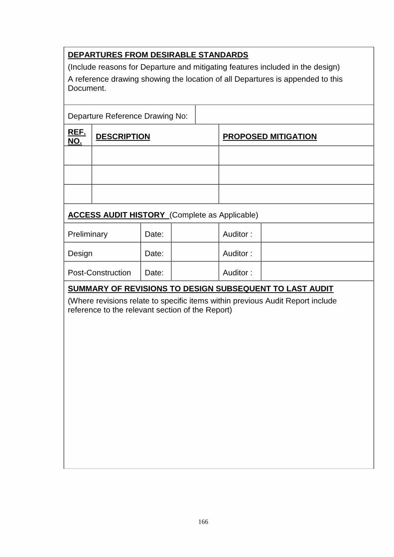
166
DEPARTURES FROM DESIRABLE STANDARDS
(Include reasons for Departure and mitigating features included in the design)
A reference drawing showing the location of all Departures is appended to this Document.
Departure Reference Drawing No:
REF. NO.
DESCRIPTION PROPOSED MITIGATION
ACCESS AUDIT HISTORY (Complete as Applicable)
Preliminary Date: Auditor :
Design Date: Auditor :
Post-Construction Date: Auditor :
SUMMARY OF REVISIONS TO DESIGN SUBSEQUENT TO LAST AUDIT
(Where revisions relate to specific items within previous Audit Report include reference to the relevant section of the Report)

167
INFORMATION SUPPLIED
The following information is supplied as part of this brief :- (X)
Previous Access Audit Reports
Safety Audit Reports
Location Plan and details of adjacent property use
General Arrangement Drawing including relevant plan dimensions and showing the location of all of the details identified below
Details
Surface Gradients - longitudinal and cross-falls
Steps, Ramps and Platforms – Long-sections, cross-sections, dimensions, tolerances, materials, finishes, colours
Hand Rails – Dimensions, materials, finishes, colours
Pedestrian and Vehicular Barriers – Dimensions, materials, finishes, colours
Surfacing and Paving – Dimensions, Tolerances, materials, finishes, colours
Kerbing, Edging, Tap Rails and Cycle Lane Dividers - Dimensions, tolerances, materials, finishes, colours
Street Furniture - Dimensions, materials, finishes, colours
Signage – pole sizes, mounting heights, materials, colours, letter fonts and sizes
Road Markings Vehicular and Pedestrian
Pedestrian Crossing Points – Detail of construction and associated features and signage
Bus Stops and Shelters – Detail of construction and associated features and signage
Lighting – type and location and light levels
Other Scheme - Specific Features (List Below)

168
Audit Report Summary Sheet
AUDIT REPORT SUMMARY SHEET FOR :- (Project Title)
Audit : (Delete as Applicable)
Preliminary Design Post-Construction
Designer : (Name, Position, Company)
Access Auditor : (Name, Position, Company)
Element of Project Designer Access Auditor
Signed
Date
Signed
Date
Signed
Date
Signed
Date