Standards for - Missouri Department of Natural Resources
41
. . Standards for ' ... ... '.. .. , .. Non-Commun it y Public Water-Supplies 1982. . . ' . . -. .. Q , PUB979
Transcript of Standards for - Missouri Department of Natural Resources

. .
Standards for '... ... '.. .. , ..
Non-Community Public Water-Supplies1982. .
. ' ..-. ..
'.:~
Q,PUB979


STANDARDS FOR NON-COMMUNITY
PUBLIC WATER SUPPLIES, 1982
PUB000979
Missouri Department of Natural Resources Division of Environmental Quality


Acknowledgement
The information appearing in this manual was compiled from Guidelines forDesign of Small Public Water Systems, Office of Public Water Supply OhioEnvironmental Protection Agency and Recommended Standards for Water Works 1982 Edition, A Report of the Committee of the Great Lakes - Upper MississippiRiver Board of Sanitary Engineers.


FORWARD
This publication has been prepared as a guide for professional engineers, andwater supply specialists engaged in the design or development of non-communitypublic water supply systems using groundwater as a source. The objective hereis to assure that new or substantially modified public water system facilitiessuch as those for factories, motels, office buildings, restaurants,campgroundsand the like will be capable of supplying water in compliance withapplicable regulations.
Its purpose is to present the requirements and procedures necessary to developan approved water supply system where connection to an existing public watersystem cannot be made at reasonable cost. Standards and guidelines for designare included.
THE DESIGN OF WATER SYSTEMS USING SURFACE WATER AS A SOURCE IS BEYOND THE SCOPEOF THIS MANUAL. Water supplies utilizing surface water must submit to thedepartment plans and specifications prepared by an engineer for review andissuance of a written approval prior to initiating construction.
The requirements, criteria and procedures described in this publicationrepresent current practices of the Missouri Department of Natural Resources.They are subject to change whenever, in the judgement of the Department, suchachange will be more effective in fulfilling its responsibility under the law.
NOTE: For sewerage, a similar publication entitled, "A Guide For the Design ofSmall Sewerage Works" may be obtained from the Water Pollution Control Program,Department of Natural Resources.


TABLE OF CONTENTSPAGE
PART 11. 0 LEGAL REQUIREMENTS 11~1 DEFINITIONS 11•2 STATUTORY REQUIREMENTS 11.3 REGULATORY ~QUlREMENTS 1
PART 22 • 0 GENERAL 32.1 PROCEDURES FOR ESTABLISHING A NON-COMMUNITY PUBLIC WATER SYSTEM 32.2 INFORMATION REQUIRED ON PLANS 52 .3 PLAN SUBMITTAL 6
PART3.03.13 . 23.33.43.53.63.73.8
3SOURCEAVAILABILITY OF WELL WATERQUALITY OF WATERWELL SITE ACCEPTANCEBASIS OF DESIGNGENERAL WELL CONSTRUCTIONAQUIFER TYPES AND CONSTRUCTION METHODS- SPECIAL CONDITIONSWELL PUMPS, DISCHARGE PIPING AND APPURTENANCESTESTING AND RECORDS
101010111114171719
PART 44.0 TREATMENT4.1 GENERAL4.2 CHLORINATION
PART 55.0 STORAGE5.1 GENERAL5.2 ELEVATED STORAGE5.3 HYDROPNEUMATIC STORAGE5 .4 GROUND LEVEL STORAGE
222222
2525252626
PART6.06.16.26.36.46.56.66.76.86.9
6DISTRIBUTION SYSTEMMATERIALSWATER MAIN DESIGNVALVESHYDRANTSINSTALLATION OF MAINSSEPARATION OF WATER MAINS, SANITARY SEWERS AND STORM SEWERSSURFACE WATER CROSSINGSCROSS-CONNECTION AND INTERCONNECTIONSWATER SERVICES AND PLUMBING
28282829292930313131
Figure 1 - Addresses of Regional OfficesFigure 2A - Well DevelopmentFigure 2B - Survey of Pressure Grout Sealing of Well CasingFigure 3 - Water Supply Data FormFigure 4 - Water Usage Suggested Guide .Figure 5 - Flow Diagram for Chlorination
4789
1'324


PART 1
1.0 Legal Requirements
1.1 Definitions
1.1.1 "Public Water System": A system for the provision to the publicofpiped water for human consumption, if such system has at leastfifteen (15) service connections or regularly serves an average ofat least twenty-five (25) individuals daily at least sixty (60)days out of the year. Such system includes: any collection,treatment, storage or distribution facilities used in connectionwith such system. A public water system is either a "communitywater system" or a "non-community water system".
1.1.2 "Community Water System": A public water system which serves atleast fifteen (15) service connections and is operated on ayear-round basis or regularly serves at least twenty-five (2S)residents on a year-round basis.
1.1.3 "Non-CotmDunity Water System": A public water system that is not acommunity water system, which has at least fifteen (15) serviceconnections or regularly serves an average of at least twenty-five(25) individuals daily at least sixty (60) days out of the year.
1.2 Statutory Requirements
1.2.1 Portions of Chapter 640 Revised Statutes of Missouri read asfollows:
*640.115. Information to be furnished-approval of supplies-systemchanges to conform to rules.-l Every municipal corporation,private corporation, company, partnership, federal establishment,state· establishment or individual supplying or authorized to supplydrinking water to the public within the state shall file with theDepartment of Natural Resources a certified copy of the plans andsurveys of the waterworks with a description of the methods ofpurification and of the source from which the supply of water isderived, and no source of supply shall be used without a writtenpermit of approval from the Department of Natural Resources, orwater dispensed to the public without first obtaining such writtenpermit of approval.
2. Construction, extension or alteration of a public water systemshall be in accordance with the rules and regulations of theDepartment of Natural Resources.
1.3 Regulatory Requirements
1.3.1 Portions of Section 10 CSR 60-3.010 of the Missouri Public DrinkingWater Regulations reads as follows:
(2) Non-community water system requirements
-1-

(A) A supplier of water which operates a non-community publicwater supply must apply in writing to the department for a permitto dispense water to the public. Non-community public water supplysystems must--
1. Present evidence to the department of the ability toproduce water meeeting applicable maximum contminant levels; and
2. Present evidence of reliable water system operation,consistent with the type of'treatment and the degree of automaticcontrol provided.
(B) Each supplier of water must notify the department, inadvance, of the intent to construct a new or expand an existingwater system.
1. Water supplies utilizing surface water must submit tothe department plans and specifications prepared by an engineer forreview and issuance of a written approval prior to initiatingconstruction.
2. Water supplies utilizing ground water
A. may, at the discretion of the department, berequired to submit plans and specifications for approval;
B. shall be constructed in accordance with thedepartment's "Standards for Non-Community Public Water Supplies,1982"; and
c. must file with the department within sixty (60)days of completion, a record of construction for all new ormodified wells on forms provided by the department.
(3) Permits to dispense water are effective until revoked. Thedepartment may modify or revoke a permit to dispense water subjectto the appeal provisions of section 640.130.4, RSMo (1978), upon afinding that any of the following events have occurred:
(A) The holder of a permit ceases to function as a publicwater supply;
(B) The holder of a permit fails to correct an operatingdeficiency or comply with these regulations within: a reasonabletime after receipt of notice from the department; or
(e) The department determines that an emergency condition ·exists in a water supply which endangers, or could be expected toendanger, the health of a person or persons consuming affectedwater.
-2-

PART 2
2.0 GENERAL
Connection to an existing approved system shall be given primaryconsideration. A ground water system may be developed if connection to anexisting system is impractical. .A system using hauled water from a publicwater system may be considered only if a supply from an existing system ora ground water system cannot be developed.
2.1 PROCEDURES FOR ESTABLISHING A NON-COMMUNITY PUBLIC WATER SYSTEM
2.1.1 Connect to an existing approved system.
a. Contact existing public water system(s) within economicalpiping distance for connection thereto.
b. If arrangements can be made to connect to an existing systemhave an engineer prepare plans for the connection anddistribution system.
2.1.2 Develop an approved ground water system.
Where there is no existing public water system within economicalpiping distance, give consideration to the development of a groundwater system:
a. Obtain from the Department of Natural Resources, requirements,design criteria and responsibilities involved.
b. Have a professional engineer prepare plans for the systemcovering well construction, treatment, storage anddistr.ibution.
c. Submit plans to the Department of Natural Resources.Construction must not commense until the formal approval letteris received from the department.
d. Obtain well site acceptance from an environmental engineer fromappropriate regional office. See map of the Department ofNatural Resources regions for address and telephone number ofthe appropriate regional office. (Figure 1)
e. Drill and develop well.
f. Arrange for collection and analysis of required·well watersamples after well has been drilled and developed.
g. Test pump the well. Pump until drawdown has stabilized.
h. Determine the treatment processes required for your proposedsystem based on the sample analyses.
i. Where a well is terminated into geological formations commonlyutilized for private domestic wells, chlorination withretention is required to assure safe bacteriological quality.

2.1.3 Develop an approved storage system using hauled water.
Where the above systems cannot be developed, use of a storage tankwith hauled water may be considered. Consult the Department ofNatural Resources.
2.2 INFORMATION REQUIRED ON PLANS
2.2.1 General location of project.
2.2.2 Site plan including
a. Location of existing wells, .isolation radius, and possiblesources of contamination.
b. Ownership of land and land use of surrounding property.
c. Location of water mains and sewer lines.
2.2.3 Construction Details
a. Well development
1. upper terminal development2. depth of well3. well screen data4. casing diameter and material5. grouting of annular space6. pit less adaptor data7. housing (if any) over upper terminal8. sampling taps9. meters
b. Treatment devices, if applicable
1. piping diagram in sufficient detail to show flow throughplant
2. details of-treatment equipment including dimensions, etc.3. water treatment plant waste disposal facilities, if
applicable4. disinfection procedures, including equipment, method,
points of application, detention, safety equipment, etc.5. other pertinent information
c. Storage
1. plant site clearwells2. system storage
a. location
d. Distribution System
1. waterline size, material and location2. disinfection procedures
NOTE ON SPECIFICATION: Separate specifications are not needed if all necessaryinformaton is shown on the plans.

2.3 . PLAN SUBMITTAL
2.3.1 Provide
a. two sets of the detailed plans and specifications submittedat least 30 working days prior to the date on which actionby the Department is desired.
b. a completed Water Supply Data Form, this form is (Figure 3) andcan be obtained from the regional office.
c. Within sixty (60) days of completion, a record of constructionfor all new or modified wells on the Well Development Form(Figure 2A) and Survey of Pressure Grout Sealing of Well Casing(Figure 2B) provided by the Department. .
2.3.2 Where an existing well is used, the following shall be provided:
a. A signed and notarized report attesting to proper wellconstruction, protection and satisfactory condition of thegrouting, casing capabilities and pitless installation device(Figure 3). .
b. Completed Water Supply Data Form (Figure 3) and WellDevelopment Form (Figure 2A) provided by the Department.
c. Copies of the chemical and radiological analyses.
d. Treatment process, if required.
-6-

ELECTRIC CONDUIT
DROP PIPE
ELECTRICLINE
DISCHARGELINE
FOOT VALVE
PUMP
SCREEN
-------------
WELL DEVELOPMENT
WELL
Aquifer ----------Depth ----
CASING
Size Depth---- -----PITLESS INSTALLATION DEVICE
Make -----------Model
Approval Type: NSF WSC --DISCHARGE LINE
Material ----------Size ----Foot Valve: Yes No ---
ELECTRICAL
Volts Hertz----- ----Phases ----Lightninq Protection: "Yes No __
PUMP
Make ------------Model -----------Capacity gpm at TDH---- --Horsepower Depth ----
SCREEN
Type ------------Materi a1 ----------Length Size---- -----

SURVEY OF PRESSURE GROUT SEALING OF WELL CASING
-
-8- FIGURE 3
Name of cementing contractor ________________________________________________________________________ Name of drilling contractor __________________________________________________________________________ Date of cement casing ______________________________________________________________________________ Static water level before sealing ____________________________ Static water level after sealing _____________________ Was water circulated before cement grout was introduced? _________________________________________________ Were crevices encountered which prevented or interfered with grouting? ______________ Depth __________________ Was any prepared compound pumped into well in an attempt to obtain circulation? _____________________________ Material used ____________________________________________ Amount ________________________________ Was cement grout forced upward from bottom of casing to grout surface? ____________________________________ If not, to what elevation? ____________________ Who determined elevation? _______________________________ What was the maximum pressure exerted on cement grout? _______________________________________________ Total amount of cement used ___________ Amount forced upward from bottom of casing ______________________ Amount introduced from top of ground _______________________________________________________________ How many hours was cement grout permitted to set before plug was drilled out? __________________________________ Give a brief narrative of cementing operation, including difficulties encountered: __________________________________ ___________________________________________________________________________________________________________ ___________________________________________________________________________________________________________ ___________________________________________________________________________________________________________ _+_________________________________________________________________________________________________________ Date _____________________________________________ Reported by ___________________________________________
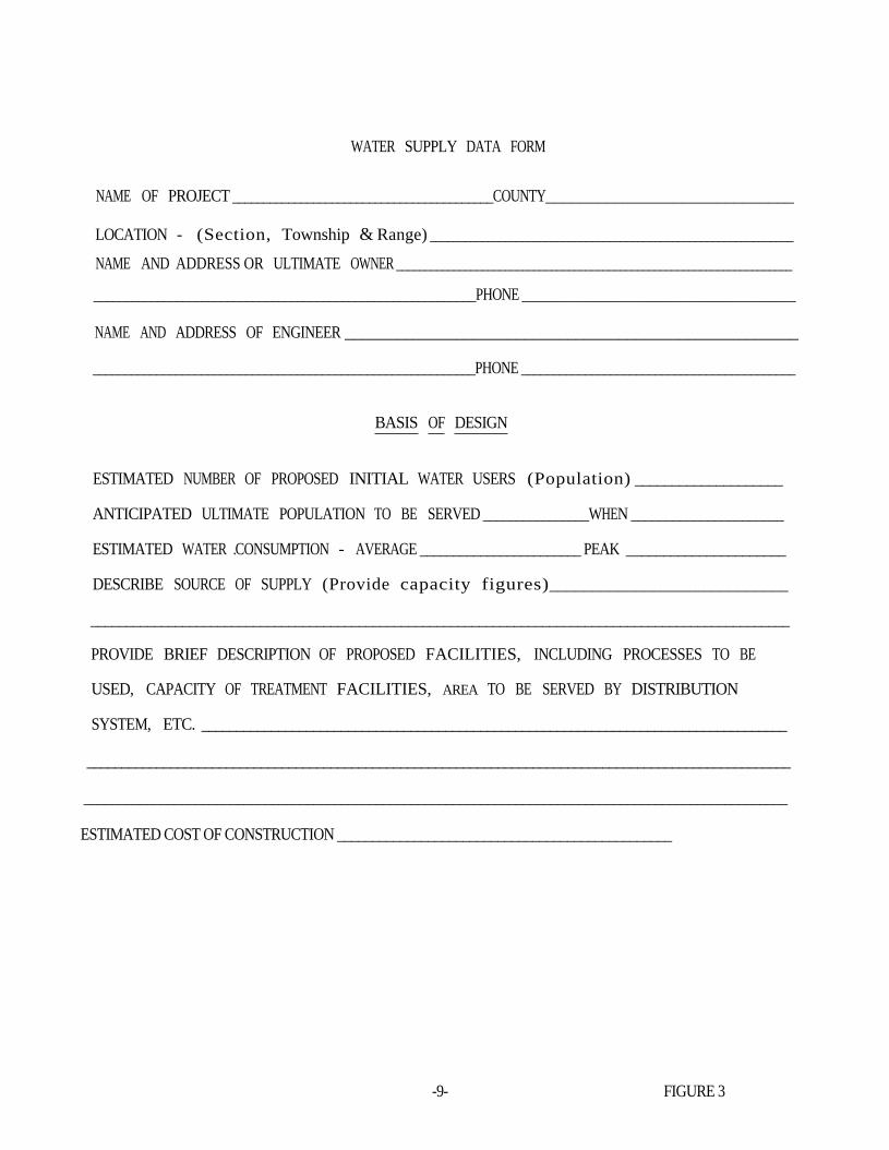
WATER SUPPLY DATA FORM
NAME OF PROJECT __________________________________________COUNTY_____________________________
LOCATION - (Section, Township & Range) _______________________________________________________________
NAME AND ADDRESS OR ULTIMATE OWNER _____________________________________________________________________
____________________________________________________________PHONE ________________________________
NAME AND ADDRESS OF ENGINEER _____________________________________________________
____________________________________________________________PHONE ___________________________________________
BASIS OF DESIGN
ESTIMATED NUMBER OF PROPOSED INITIAL WATER USERS (Population) ____________________
ANTICIPATED ULTIMATE POPULATION TO BE SERVED ________________WHEN ______________________
ESTIMATED WATER .CONSUMPTION - AVERAGE ________________________ PEAK ______________________
DESCRIBE SOURCE OF SUPPLY (Provide capacity figures)____________________________
___________________________________________________________________________________________________
PROVIDE BRIEF DESCRIPTION OF PROPOSED FACILITIES, INCLUDING PROCESSES TO BE
USED, CAPACITY OF TREATMENT FACILITIES, AREA TO BE SERVED BY DISTRIBUTION
SYSTEM, ETC. ____________________________________________________________________________________
_____________________________________________________________________________________________________
_____________________________________________________________________________________________________
ESTIMATED COST OF CONSTRUCTION ________________________________________________
-9- FIGURE 3

PART 3
3.0 SOURCE
3.1 AVAILABILITY OF WELL WATER
3.1.1 The availability of an adequate well water supply is a majorconsideration in the selection of a well site.
3.1.2 In areas known to have groundwater problems such as inadequatequantity or unacceptable quality, acceptance of the well site maybe withheld pending drilling of a test well and submission ofinformation relative to yield and quality.
3.1.3 Information on the availability of groundwater can be obtained fromthe Department of Natural Resources, Division of Geology and LandSurvey, Rolla, Missouri.
3 •2 QUALITY OF WATER
3.2.1 Microbiological Quality
a. Disinfection of every new, modified or reconditioned groundwater source
1. shall be provided after completion of work, if asubstantial period elapses prior to test pumping orplacement of permanent pumping equipment, and;
2. shall be provided after placement of permanent pumpingequipment.
b. After disinfe"ction, one or more consecutive, safemicrobiological samples shall be taken from the well, analysisshall be made in a Department of Natural Resources approvedlaboratory.
"3.2.2 Physical and Chemical Quality
a. Every new groundwater source shall be examined for applicablephysical, chemical characteristics by tests of a representativesample in a laboratory certified by the Department of NaturalResources.
b. Samples shall be collected at the conclusion of the testpumping procedures.
c. The Department of Natural Resources will advise on methods andtypes of treatment required on the basis of the results ofthose analyses.
3.2.3 Every new, modified or reconditioned groundwater source shall beexamined for radiological activity as required by the Department ofNatural Resources.
-10-

3.3 . WELL SITE ACCEPTANCE
3.3.1 Requirements
The well site(s) for a non-community public water supply are to beaccepted by the regional office of the Department of Natural
Resources. Sites for new wells are to be accepted before the wells are drilled.
3.3.2 Procedures
Provide a plot plan of the area within 1000 feet of the well site,drawn to scale and showing:
a. proposed well location to the nearest quarter-quarter section;
b. property lines, use of adjacent properties, other wells;
c. existing roads or highways;
d. buildings (proposed and existing), parking lots, streams,ponds, lakes;
e. sanitary sewers, septic tanks, buried fuel tanks chemicalstorage, and any other sources or potential sources ofcontamination.
3.3.3 Isolation standards
a. Unless the geology and aquifer hydraulics dictate greater orlesser distances, acceptance of the well site will be based oncompliance with the following Radii:
Source of Possible Contamination
Sanitary sewer linesSewage treatment plantsseptic tanks, disposal fields
Chemical storage, buried fueltanks
Lakes or streams
Isolation Radius
50 ft.
300 ft.
300 ft.50 ft.
b. The owner of the well should own all the land within a 50 feetisolation radius. Any use of the land within the isolationradius must have the approval of the Department of NaturalResources.
3.4 BASIS OF DESIGN
3.4.1 Requirements
a. The estimated average daily water demand shall be determined byusing either the chart (Figure 4) or historical water usedata. Calculate the peak daily and hourly demands usingfactors not less than those shown below:

1. Peak daily demand equals average daily demand x 2.0
2. Peak hourly demand equals average daily hourly demand x 10
b. The primary well system must be capable of providing anadequate supply of water during normal and peak usage periods.In addition, standby or alternate spurces may be required incase of emergency, pump failure, etc.
3.4.1.1 Well capacity
The capacity of the wells and pumps in a hydropneumaticpressure system are to be at least ten times the averagedaily water consumption rate. Where the aquifer cannotsupport this withdrawal rate, a storage tank with highservice pumping may be used to meet this peak requirementprovided the wells can meet the peak .daily demand.
3.4.2 Geological data
a. shall be determined from samples collected at 5-foot intervalsand at each pronounced change i n formation.
b. shall be recorded and samples submitted to the Division ofGeology and Land Survey.
c. shall be supplemented with information on accurate record ofdrill hole diameter and depths, assembled order of size andlength of casing and liners, grouting depths, formationspenetrated, water levels, and location of any blast charges.
-12-

WATER USAGE
SUGGESTED GUIDE
Place Gallons Per Day
0.2 per sq. ft. of floor space3-5 per swimmer5-7 per SW1mmer125 per trailer or tent space
50 per person50 per person
Assembly HallsBowling Alleys (no food service)Churches (small)Churches (large with kitchen)Country ClubsDance HallsDrive-In TheatersFactories (no showers)Factories ·(with showers)Food Service OperationsOrdinary Restaurant (no 24-hour)24-hour RestaurantBanquet RoomsRestaurant along FreewayTavern (very little food service)Curb Service (drive-in)Vending Machine Restaurants
Hospitals (no resident personnel)Institutions (residents)Laundries (coin operated)MotelsNursing and Rest Homes
tI
II
Office BuildingsRecreational Vehicle Parks and CampsRetail StoreSchools - Elementary
- High and Junior HighService Stations
"
Shopping Centers (no food ,service orlaundries)
Swimming Pools (average)With hot water shower,
Travel Trailer Parks and CampsVacation CottagesYouth and Recreation Camps
275
3-55-7
5025
2535
35505
1003550
1003001004001001501005020
125201520
1000500
per seatper laneper sanctuary seatper sanctuary seatper memberper personper car spaceper employeeper employee
per. seatper seatper seatper seatper seatper car spaceper seatper ' bedper personper standard S1ze machineper unitper patientper resident employeeper non-resident employeeper employeeper trailer or tent spaceper employeeper pupilper pupilfirst bay or pump islandadditional bay or pump island
-13-
FIGURE 4

•
3.5 GENERAL WELL CONSTRUCTION
3.5.1 Minimum protected depths
Minimum protected depths of drilled wells shall provide watertightconstruction to such depth as may be required by the department, to
a. exclude contamination, and
b. seal off formations that are, or may be, contaminated or yieldundesirable water.
3.5.2 Temporary steel casing
Temporary steel casing used for construction shall be capable ofwithstanding the structural load imposed during its installationand removal.
3.5.3 Permanent steel casing pipe shall
a. be new pipe meeting AWWA Standard A-100, ASTM or APIspecifications for water well construction,
b. have minimum weights and thickness indicated in Table 1,
c. have additional thickness and weight if minimum thickness isnot considered sufficient to assure reasonable life expectancyof a well,
d. be capable of withstanding forces to which it is subjected,
e. be equipped with a drive-shoe when driven, and
f. have full circumferential welds or threaded coupling joints.
3.5.4 Nonferrous casing materials
a. Approval of the use of any nonferrous material as well casingshall be subject to special determination by the Departmentprior to submission of plans and specifications.
b. Nonferrous material proposed as a well casing must be" resistantto the corrosiveness of the water and to the stresses to whichit will be .subjected during installation, grouting andoperation.
3.5.5 Packers
Packers shall be of material that will not impart taste, odor,toxic substance or bacterial contamination to the well water.
3.5.6 Screens shall
a. be constructed of materials resistant to damage by chemicalaction of groundwater or cleaning operations,
-14-

b. have size of openings based on sieve analysis of formationand/or gravel pack materials,
c. have sufficient diameter to provide adequate specific capacityand low aperture entrance velocity. Usually the entrancevelocity should not exceed 0.1 feet per second,
d. be installed so that the pumping water level remains above thescreen under all operating conditions,
e. where applicable, be designed and installed to permit removalor replacement without adversely affecting water-tightconstruction of the well, and
f. be provided with a bottom plate or washdown bottom fitting ofthe same material as the screen.
3.5.7 Grouting requirements
All permanent well casing shall be surrounded by a minimum of1 1/2 inches of grout to the depth required by the Department. Alltemporary construction casings shall be removed. Where removal isnot possible or practical, the casing shall be withdrawn at leastfive feet to insure grout" contact with the native formation.
a. Neat cement grout
1. Cement conforming to ASTM standard C150 and water, with notmore than six gallons of water per sack of cement, must beused for 1-1/2 inch openings.
2. Additives may be used to increase fluidity subject toapproval by the Department.
b. Application
1. Sufficient annular opening shall be provided to permit aminimum of 1 1/2 inches of grout around permanent casings,including couplings.
2. Prior to grouting through creviced or fractured formations,bentonite or similar materials may be added to the annularopening, in the manner indicated for grouting.
3. When the annular opening is less than four inches, groutshall be installed under pressure by means of a grout pumpfrom the bottom of the annular opening upward in one.continuous operation until the annular opening is filled.
4. When the annular opening is four or more inches and lessthan 100 feet in depth, it may be placed by gravity througha grout pipe installed to the bottom of the annular openingin one continuous operation until the annular opening isfilled.
-15-

5. After cement grouting is applied, work on the well shall bediscontinued until the cement has properly set.
c. Guides
The casing must be provided with sufficient guides welded tothe casing to permit unobstructed flow and uniform thickness ofgrout.
3.5.8 Upper terminal well construction
a. Permanent casing for all groundwater sources shall. project atleast 12 inches above the pumphollse floor or concrete apronsurface and at least 18 inches above final ground surface.
b. The top of the well casing at sites subject to flooding shallterminate at least four feet above the 100 year flood level orthe highest known flood elevation, whichever is higher, or asthe department directs.
3.5.9 Capping requirements
a. A welded metal plate or a threaded cap is the preferred methodfor capping a well.
b. A properly fitted, firmly driven, solid wooden plug is theminimum acceptable method of capping a well until pumpingequipment is installed.
c. At all times during the progress of work, the contractor shallprovide protection to prevent tampering with the well orentrance of foreign materials.
3.5.10 Well abandonment
a. Test wells and groundwater sources which are not in use shallbe sealed by such methods as necessary to restore the.controlling geological conditions which existed prior toconstruction or as directed by the Division of Geology and LandSurvey.
b. Wells to be abandoned shall
1. be sealed to prevent undesirable exchange of water from oneaquifer to another,
2. preferably be filled with neat cement grout,
3. have fill materials other than cement grout or concrete,disinfected and free of foreign materials, and,
4. when filled with cement grout or concrete, these materialsshall be applied to the well hole through a pipe, tremie,or bailer.
c. The Division of Geology and Land Survey should be informedwithin 60 days of well sealing completion.
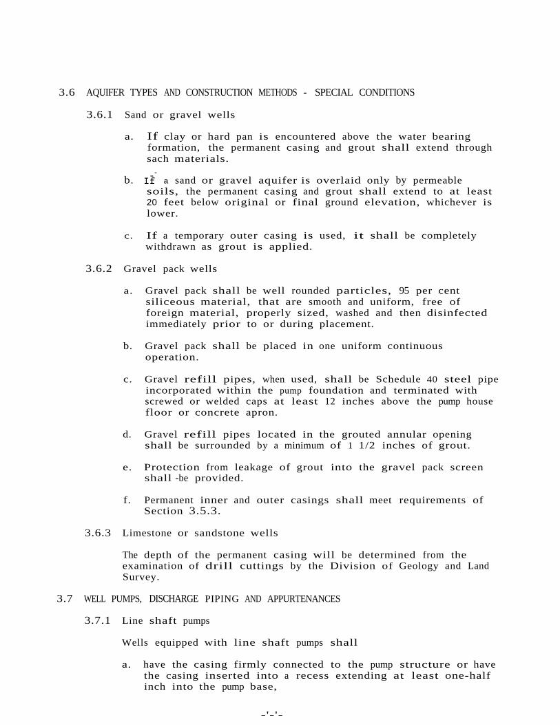
3.6 AQUIFER TYPES AND CONSTRUCTION METHODS - SPECIAL CONDITIONS
3.6.1 Sand or gravel wells
a. If clay or hard pan is encountered above the water bearingformation, the permanent casing and grout shall extend throughsach materials.
-b. If a sand or gravel aquifer is overlaid only by permeable
soils, the permanent casing and grout shall extend to at least20 feet below original or final ground elevation, whichever islower.
c. If a temporary outer casing is used, it shall be completelywithdrawn as grout is applied.
3.6.2 Gravel pack wells
a. Gravel pack shall be well rounded particles, 95 per centsiliceous material, that are smooth and uniform, free offoreign material, properly sized, washed and then disinfectedimmediately prior to or during placement.
b. Gravel pack shall be placed in one uniform continuousoperation.
c. Gravel refill pipes, when used, shall be Schedule 40 steel pipeincorporated within the pump foundation and terminated withscrewed or welded caps at least 12 inches above the pump housefloor or concrete apron.
d. Gravel refill pipes located in the grouted annular openingshall be surrounded by a minimum of 1 1/2 inches of grout.
e. Protection from leakage of grout into the gravel pack screenshall -be provided.
f. Permanent inner and outer casings shall meet requirements ofSection 3.5.3.
3.6.3 Limestone or sandstone wells
The depth of the permanent casing will be determined from theexamination of drill cuttings by the Division of Geology and LandSurvey.
3.7 WELL PUMPS, DISCHARGE PIPING AND APPURTENANCES
3.7.1 Line shaft pumps
Wells equipped with line shaft pumps shall
a. have the casing firmly connected to the pump structure or havethe casing inserted into a recess extending at least one-halfinch into the pump base,
-'-'-

b. have the pump foundation and base designed to prevent waterfrom coming into contact with the joint.
3.7.2 Submersible pumps
Where a submersible pump is used
a. the top of the casing shall be effectively sealed against theentrance of water under all conditions of vibration or movementof conductors or cables, and
b. the electrical cable shall be firmly attached to the riser pipeat 20 foot intervals or less.
3.7.3 Discharge piping
a. The discharge piping shall
1. be protected "against the entrance of contamination,
2. be equipped with a smooth nosed sampling tap located at apoint where positive pressure is maintained,
3. where applicable, be equipped with an air release-vacuumrelief valve located upstream from the check valve, withexhaust/relief piping terminating in a downturned positionat least 18 inches above the floor and covered with a 24mesh corrosion resistant screen,
4. be valved to permit test pumping and control of each well,
5. have all exposed piping, valves and appurtenances protectedagainst physical damage and freezing.
6. be properly anchored to prevent movement, and
7. be protected against surge or water hammer.
b. The discharge piping should be provided with a means of pumpingto waste, but shall not be directly connected to a sewer.
3.7.4 Pitless well units
a. Pitless units shall
1. be shop-fabricated from the point of connection with thewell casing to the unit cap or cover,
2. be threaded or welded to the well casing,
3. be of watertight construction throughout,
4. be of materials and weight at least equivalent andcompatible to the casing,
-18-
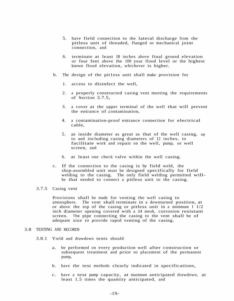
5. have field connection to the lateral discharge from thepitless unit of threaded, flanged or mechanical jointconnection, and
6. terminate at least 18 inches above final ground elevationor four feet above the 100 year flood level or the highestknown flood elevation,. whichever is higher.
I
b. The design of the pit1ess unit shall make provision for
1. access to disinfect the well,
2. a properly constructed casing vent meeting the requirementsof Section 3.7.5,
3. a cover at the upper terminal of the well that will preventthe entrance of ,contamination,
4. a contamination-proof entrance connection for electricalcable,
5. an inside diameter as great as that of the well casing, upto and including casing diameters of 12 inches, tofacilitate work and repair on the well, pump, or wellscreen, and
6. at least one check valve within the well casing.
c. If the connection to the casing is by field weld, theshop-assembled unit must be designed specifically for fieldwelding to the casing. The only field welding permitted willbe that needed to connect a pitless unit to the casing.
3.7.5 Casing vent
Provisions shall be made for venting the well casing toatmosphere. The vent shall terminate in a downturned position, ator above the top of the casing or pitless unit in a minimum 1 1/2inch diameter opening covered with a 24 mesh, corrosion resistantscreen. The pipe connecting the casing to the vent shall be ofadequate size to provide rapid venting of the casing.
3.8 TESTING AND RECORDS
3.8.1 Yield and drawdown tests should·
a. be performed on every production well after construction orsubsequent treatment and prior to placement of the permanentpump,
b. have the test methods clearly indicated in specifications,
c. have a test pump capacity, at maximum anticipated drawdown, atleast 1.5 times the quantity anticipated, and
-19-

d. provide for continuous pumping for at least 24 hours or untilstabilized drawdown has continued for at least six hours whentest pumped at 1.5 times the design pumping rate,
e. provide the following data:
1. test pump capacity-head characteristics,2. static water level,3. depth of test pump setting, and
·4. time of starting and ending each test cycle; and
f. provide recordings and graphic evaluation of the following atone hour intervals or less as may be required by theDepartment:
1. pumping rate,2. pumping water level,3. drawdown, and4. water recovery rate and levels.
-20-

Table 1
STEEL PIPE*
·SIZEDIAMETER(inches)
THICKNESS( i n c h e s )
WEIGHT PER FOOT(pounds)
EXTERNAL INTERNAL PLAIN ENDS(calculated)
WITHTHREADS
ANDCOUPLINGS(nominal)
6 id. 6.625 6.065 0.280 18.97 19.188 8.625 7.981 0.322 28.55 . 29.35
10 10.750 10.020 0.365 40.48 41.8512 10.750 12.000 0.375 49.56 51.1514 od. 14.000 13.250 0.375 54.57 57.0016 16.000 15.250 0.375 62.5818 18.000 17.250 0.375 70.5920 20.000 19.250 0.375 78.6022 22.000 21.000 0.500 114.8124 24.000 23.000 ' 0.500 125.4926 26.000 25.000 '0.500 136.1728 28.000 27.000 0.500 146.8530 30.000 29.000 0.500 157.5332 32.000 31.000 0.500 168.2134 34.000 33.000 0.500 178.8936 36.000 35.000 0.500 189.57
* Abstracted from American Water Works Association Standards for deep wells,AWWA AIOO
-21-
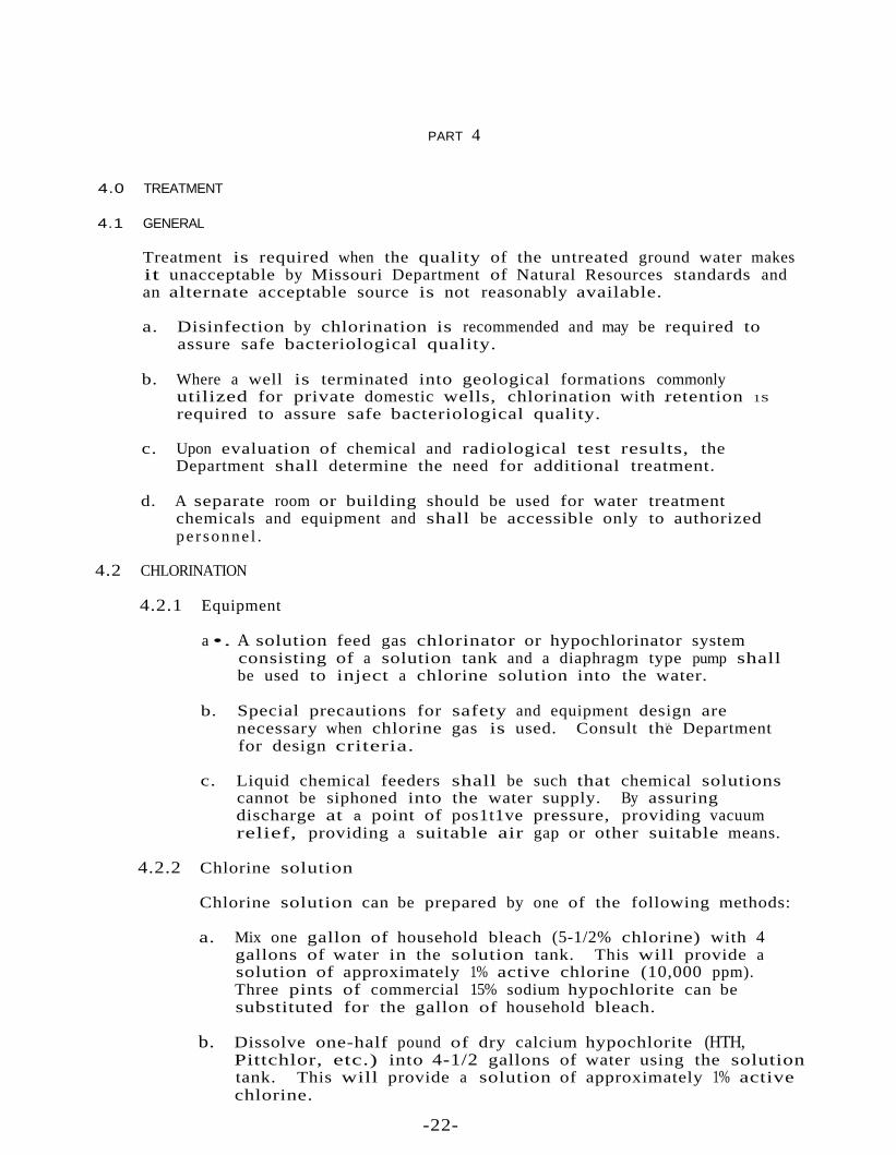
PART 4
4.0 TREATMENT
4.1 GENERAL
Treatment is required when the quality of the untreated ground water makesit unacceptable by Missouri Department of Natural Resources standards andan alternate acceptable source is not reasonably available.
a. Disinfection by chlorination is recommended and may be required toassure safe bacteriological quality.
b. Where a well is terminated into geological formations commonlyutilized for private domestic wells, chlorination with .retention 1S
required to assure safe bacteriological quality.
c. Upon evaluation of chemical and radiological test results, theDepartment shall determine the need for additional treatment.
d. A separate room or building should be used for water treatmentchemicals and equipment and shall be accessible only to authorizedper sonne l .
4.2 CHLORINATION
4.2.1 Equipment
a •. A solution feed gas chlorinator or hypochlorinator systemconsisting of a solution tank and a diaphragm type pump shallbe used to inject a chlorine solution into the water.
b. Special precautions for safety and equipment design arenecessary when chlorine gas is used. Consult th"e Departmentfor design criteria.
c. Liquid chemical feeders shall be such that chemical solutionscannot be siphoned into the water supply. By assuringdischarge at a point of pos1t1ve pressure, providing vacuumrelief, providing a suitable air gap or other suitable means.
4.2.2 Chlorine solution
Chlorine solution can be prepared by one of the following methods:
a. Mix one gallon of household bleach (5-1/2% chlorine) with 4gallons of water in the solution tank. This will provide asolution of approximately 1% active chlorine (10,000 ppm).Three pints of commercial 15% sodium hypochlorite can besubstituted for the gallon of household bleach.
b. Dissolve one-half pound of dry calcium hypochlorite (HTH,Pittchlor, etc.) into 4-1/2 gallons of water using the solutiontank. This will provide a solution of approximately 1% activechlorine.
-22-

4.2.3 Installation
Install hypochlorinator pump to operate when the well pumpoperates. The injection point shall be before the pressure andretention tanks. If a softener is used, the injection point shouldbe after the softener and before the pressure and retentiontanks. (Figure 5)
t
The pressure tank must be sized and designed to permit a fu11 30minutes contact time or a separate retention tank must beprovided. A pressure tank that is connected to the main line by asingle pipe is considered as floating on the system. This cannot .be considered as providing chlorine contact time.
The feed rate (pump setting) necessary to obtain the desiredresidual can be determined by experimentation using DPD (N, ND i e t h y l - p ~ P h e n y l e n e Diamine) chlorine test kit.
The diagrams on the next page illustrates typical chlorinationinstallations.
4~2.4 Retention time
For bacteriological control, 30 minutes chlorine contac't time shallbe maintained prior to distribution.
4.2.5 Chlorine content
During the retention period, a m1n1mum free chlorine residual of1.0 mg/l shall be maintained.
In the distribution system, a m1n1mum free chlorine residual of 0.2mg/l shall be maintained.
Chlorine content shall be measured by the DPD method.
CAUTION:
HYPOCHLORITES ARE STRONG OXIDANTS! AVOID STORING OIL OR OTHER COMBUSTIBLEMATERIALS IN THE CHLORINATION AREA.
-23-

.ELECTRICAL CONTROL LINES----------------------------I I I
I I II . I II I II II II CHLORINATOR
I RETENTION PRESSUREI. TANK TANKII
TO DISTRIBUTION
_----~w~~~~~~~~-----------I I II I II I II I II ION ~CHLORINATOR II EXCHANGE II SOFTENER RETENTION PRESSUREI TANK TANK
II
. TO DISTRIBUTION
CHLORINATION WITH ION EXCHANGE SOFTENING- "),.- 'FTCIJRE

PART 5
5 .0 STORAGE
5.1 GENERALStorage and pumping facilities) shall be adequate to maintain a mln1mumof 20 psi throughout the distributiqn system under peak operatingconditions.
Storage may take the form of elevated, standpipe, hydropneumatic, groundlevel or clear well tankage.
Where well capacity is less than peak demand (ten times average daily. demand), storage may be utilized to reduce the demand on the well.
Storage structures shall follow current AWWA and ASTM Standards wheneverapplicable.
Storage structures shall be disinfected and proven bacterially safe priorto being placed into operation. A 24-hour contact period using a 50 ppmfree chlorine solution is one acceptable method.
Fire flow requirements established by the State Insurance Services Officeshould be met where fire protection is provided.
5.2 ELEVATED AND STANDPIPE STORAGE
Elevated or standpipe storage should be provided for systems where usageexceeds 30,000 gpd. Storage at least equal to average daily demand isrecommended.
5.2.1 Standards
Storage tanks shall conform to the following:
a. The tank shall be constructed in accordance with AWWA Standards
including D-lOO.
b. The tank shall be painted in accordance with AWWA StandardD-I02.
c. The tank shall be disinfected in accordance with AWWA StandardD-105.
5.2.2 Design Criteria
a. Head range of the elevated tank is not to exceed 30 feet.
b. Tank must be provided with an overflow which is brought down toan elevation of 12" to 24" above ground surface, anddischarged over a drainage inlet or splash plate.
c. The tank should include entrance manholes with locked hatches,a screened vent and an OSHA approved access ladder.
-5-

d. A valving arrangement must be provided to allow the tank to beremoved from service.
e. A drain must be provided.
f. Security measures must be provided including chain link fence,air craft warning light, etc. as appropriate.
g. A low l e v e l warning light and/or alarm must be provided.
h. A suitable control system must be provided (i.e. telemetering).
5.3 HYDROPNEUMATIC STORAGE
Hydropneumatic storage is considered primarily as an electrical pumpcontrol mechanism and not as true storage.
5.3.1 Standards
Hydropneumatic tanks and their installations shall conform to thefollowing:
a. Gross volume in gallons of the hydropneumatic tank shall be atleast ten times the capacity in gpm of the largest supplyingpump.
b. Delivery volume in gallons of water from a bladder typehydropneumatic tank(s) shall be at least 3.0 times the capacityin gpm of the largest supplying pump.
c. The tanks shall be installed above normal ground level. Earthmounding over the tank is not acceptable.
d. Tanks less than 1000 gallons should be completely housed andheated for protection from both physical damage and freezing.
e. Tanks shall be provided with a bypass to permit operation ofthe system when they are out of service.
f. Tanks shall be provided with a drain, a pressure gauge, an airblow-off, a means of adding air, a pressure-activated off/onswitch to control the supply pump, and a sight glass.
g. Tanks of 1,000 gallons' capacity and larger shall be providedwith a manhole.
h. The tanks shall meet ASME code requirements and/or state andlocal laws and regulations for unfired pressure vessels.
5 .4 GROUND LEVEL STORAGE
Buried tanks shall be of reinforced concrete construction.
-26-
5.4.1 Standards - General
Ground level storage tanks shall conform to the following:
a. The top of the tank shall not be less than two feet abovenormal ground surface.
b. The bottom of the tank shal l be above the normal ground watertable and the maximum flood level.
c. The tank shall be constructed no closer than 50 feet to sewers,drains, standing water and other sources of pollution.
d. The tank shall be watertight and constructed to prevent entryof birds, animals, insects, and excessive dust.
·e. Security shall be provided by fencing, locks and other measuresas required to prevent trespassing and vandalism.
f. The tank shall not have a direct connection to a sewer or stormdrain.
g. A screened vent should terminate i n an inverted U at least 24inches above -ground level.
h. An access manhole should be located above the waterline of thetank. The access manhole shall be framed at least four inchesabove the surface of the roof and fitted with a solid,watertight, locked cover which overlaps the framed opening atleast two inches.
i. A screened overflow must be installed so as to have a minimumair gap of 12 inches above a splash block located at groundsurface. The overflow shall not connect directly to a sewer orstorm drain.
j. Grading shall be carried out so that surface water drains awayfrom the tank.
5.4.2 Standards - Fiber Glass Tanks
Fiber glass storage tank installations shall have the followingexceptions and additions to the above:
a. Tanks should be pressure tested according to manufacturer'sinstruction and fittings soap bubble tested beforeinstallation.
b. Tanks shall be anchored to a concrete pad and back filled withpea gravel, with clean and free flowing 1/8"-1/2" diameterstone crushings meeting ASTM C-33, or other backfill materialmeeting manufacturer1s recommendations.
c. Combined weight of the empty tank, the concrete pad and thebackfill supported on the concrete pad shall be sufficient toprevent flotation of the empty tank.
PART 6 - DRAFT
6.0 DISTRIBUTION SYSTEMS
6 • 1 MATERIALS
6.1.1 Standards, materials selection
Pipe fittings, valves and fire hydrants shall conform to the lateststandards issued by the AWWA, if such standards exist, and beacceptable to the department. In the absence of such standards,materials meeting applicable Product Standards and acceptable tothe department may be selected.
6.1.2 Used materials
Water mains which have been used previously for conveying potablewater may be reused provided they meet the above standards and havebeen restored practically to their original condition.
6.1.3 Joints
Packing and jointing materials used in the joints of pipe shallmeet the standards of the AWWA and the department. Pipe havingmechanical joints or slip-on joints with rubber gaskets ispreferred.
6.2 WATER MAIN DESIGN
6.2.1 Pressure
All water including those not designed to provide fire protection,shall be sized after a hydraulic analysis based on flow demands andpressure requirements. The system shall be designed to maintain aminimum pressure of 20 psi at ground level at all points in thedistribution system under all conditions of flow. The normalworking pressure in the distribution system should be approximately60 psi and not less than 35 psi.
6.2.2 Diameter
The minimum size of waterjmain for providing fire protection andserving fire hydrants shall be six-inch diameter.
6.2.3 Fire protection
When fire protection 1S to be provided, system design should besuch that fire flows and facilities are in accordance with therequirements of the state Insurance Services Office.
6.2.4 Hydrants
Water mains not designed to carry fire-flows shall not have firehydrants connected to them.
-28-

6.2.5 Dead ends
Dead ends shall be minimized by looping of all mains wheneverpractical.
6.2.6 Flushing
Where :_dead-end mains occur they shall be provided with a firehydrant if flow and pressure are sufficient, or with an approvedflushing hydrant or blow-off for flushing purposes. Flushingdevices should be sized to pravide flows which will give a velocityof at least 2.5 feet per second in the water main being flushed.No flushing device shall be directly connected to any sewer.
6.3 VALVES
6.3.1 Sufficient valves shall be provided on water mains so thatinconvenience and sanitary hazards will be minimized duringrepairs. Valves should be located at all branch lines.
6 .4 HYDRANTS
6.4.1 Location and spacing
Hydrants should be provided as recommended by the state InsuranceServices Office. Generally, hydrant spacing may range from 350 to600 feet depending on the area being served.
6.5 INSTALLATION OF MAINS
6.5.1 Standards
Specifications shall incorporate the provisions of the AWWAstandards and/or manufacturer's recommended installationprocedures.
6.5.2 Bedding
A continuous and uniform bedding shall be provided in the trenchfor all buried pipe. Backfill material shall be tamped in layersaround the pipe and to a sufficient height above the pipe toadequately support and protect the . pipe. Stones found in thetrench shall be removed for a depth of at least six inches belowthe bottom of the pipe.
6.5.3 Cover
All water mains shall be covered with sufficient earth or otherinsulation to prevent freezing.
6 . 5 . 4 Blocking
All tees, bends, plugs and hydrants shall be provided with reactionblocking, tie rods or joints designed to prevent movement.
-29-
6.5.5 Pressure and leakage testing
All types of installed pipe shall be pressure tested and leakagetested in accordance with the latest edition of AWWA Standard eGOD.
6.5.6 Disinfection
All new, cleaned or repaired water mains shall be disinfected inaccordance with AWWA Standard C601. The specifications shallinclude detailed procedures for the adequate flushing,disinfection, and microbiological testing of all water mains.
6.6 SEPARATION OF WATERMAINS, SANITARY SEWERS AND STORM SEWERS
6.6.1 Parallel installation
Water mains shall be laid at least 10 feet horizontally from anyexisting or proposed sewer. The distance shall be measured edge toedge. In cases where it is not practical to maintain a ten footseparation, the reviewing authority may allow deviation on acase-by-case basis, if supported by data from the design engineer.Such deviation may allow installation of the water main closer to asewer, provided that the water main is laid in a separate trench oron an undisturbed earth shelf located on one side of the sewer atsuch an elevation that the bottom of the water main is at least 18inches above the top of the sewer.
6.6.2 Crossings
Water mains crossing sewers shall be laid to provide a minimumvertical distance of 18 inches between the outside of the watermain and the outside of the sewer. This shall be the case wherethe water main is either above or below the sewer. At crossings,one full length of water pipe shall be located so both joints willbe as far from the sewer as possible. Special structural supportfor the water and sewer pipes may be required.
6.6.3 Exception
The department must specificailly approve any variance from therequirements of Sections 6.6.1 and 6.6.2 when it is impossibletoobtain the specified" separation distances.
6.6.4 Force ma1ns
There shall be at least a 10 foot horizontal separation betweenwater mains and sanitary sewer force mains. There shall be an 18inch vertical separation at crossings as required in Section 6.6.2.
6.6.5 Sewer manholes
No water pipe shall pass,through or come in contact with any partof a sewer manhole.
-30-

6.7 SURFACE WATER CROSSINGS
6.7.1 Surface water crossings, whether over or under water, presentspecial problems. The department should be consulted before finalplans are prepared.
6.8 CROSS-CONNECTIONS AND INTERCONNECTIONS
6.8.1 Cross~connections
There shall be no connection between the distribution system andany pipes, pumps, hydrants, or tanks whereby unsafe water or othercontaminating materials may be discharged or drawn into the system.
6.8.2 Cooling water
Neither steam condensate nor cooling water from.engine jackets orother heat exchange devices shall be returned to the potable watersupply.
6.8.3 Interconnections
The approval of the Department shall be obtained forinterconnections between potable water supplies.
6.9 WATER SERVICES AND PLUMBING
6.9.1 Plumbing
Water services and plumbing should conform to relevant local and/orstate plumbing codes, or to the National Plumbing Code.
-31-

PUB979
Printed on recycled paper