Standardized single stage gear units with parallel shafts ...h2ocooling.com/content/uploads/Hansen...
76
D JA L J 4xT DN RF LR LP LN J DNA* RFA LRA* JA Standardized single stage gear units with parallel shafts Réducteurs standard à un étage à arbres parallèles horizontaux Einstufige Normgetriebe mit parallelen horizontalen Wellen Reductores normalizados de ejes paralelos de una etapa 233 EFDSb
Transcript of Standardized single stage gear units with parallel shafts ...h2ocooling.com/content/uploads/Hansen...
D
JA
LJ
4xT
DNRF
LRLP
LN
J
DNA*RFA
LRA*
JA
HF
Standardized single stage gear units with parallel shafts
Réducteurs standard à un étage à arbres parallèles horizontaux
Einstufi ge Normgetriebe mit parallelen horizontalen Wellen
Reductores normalizados de ejes paralelos de una etapa
233 EFDSb
ansen
Les réducteurs Hansen P4
L' expérience acquise grâce à une étroite collaboration avec leclient durant des années, a permis à Hansen IndustrialTransmissions nv de concevoir une gamme de réducteurs indus-trielles à plusieurs trains d'engrenages Hansen P4.
Cette quatrième génération de réducteurs standard à plusieursétages, mise sur le marché depuis 1993, est le leader sur le mar-ché quant à qualité et technologie. En plus elle se caractérise parune fiabilité et une solidité excellentes.
Pour compléter son programme de réducteurs à plusieurs étagesHansen P4, Hansen Industrial Transmissions nv lance sur le mar-ché une nouvelle gamme de réducteurs à un étage, innovationparfaitement adaptée aux applications qui demandent de petitsrapports de réduction comme: les machines à papier, les pompes,les compresseurs, etc.
Fiabilité, solidité, utilité sont les exigences principales de laclientèle. Elles ont été combinées avec un plus haut rendement,un bruit réduit et flexibilité pour une adaptation aux applicationsspécifiques.
Nos ingénieurs sont parvenus à trouver un équilibre parfait entrepuissance mécanique, puissance thermique et capacité des roule-ments, tout en respectant la tradition de Hansen industrialgearboxes de procurer une solution économique et de haute qua-lité.
The range of Hansen P4 single stagegear units caters for:
� five sizes with parallel, horizontal shafts
� two mounting positions
� R 20 range of ratios from 1.20 to 5.60
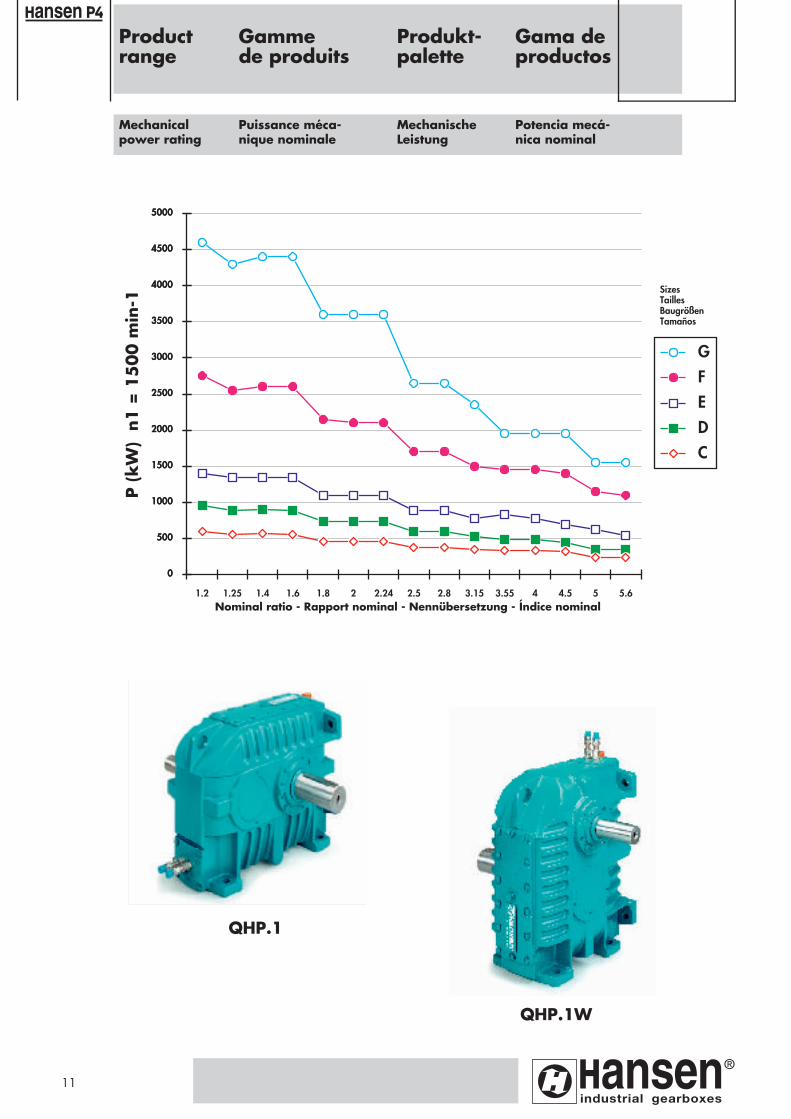
� mechanical power ratings of 100 kW up to 4 MW.
The Hansen P4 gear units
The experience gained through years of close co-operation withthe customer, enabled Hansen Industrial Transmissions nv tocreate the innovative Hansen P4 range of industrial gear units.This fourth generation of standardised, multistage gear units,launched in 1993, is market leading in quality and technology,and excels in reliability and durability.
To complement the current Hansen P4 programme of multistagegear units, Hansen Industrial Transmissions nv has introduced abrand-new and innovative range of single stage gear units,suitable for various applications requiring small reduction ratios,such as paper machines, pumps, compressors, etc.
Reliability, durability and serviceability - our customers' main re-quirements - have been combined with improved efficiency, lownoise and fitness for use.
Our design team achieved an unprecedented balance betweenmechanical, thermal and bearing ratings, respecting Hansen'sindustrial gearboxes tradition of providing top quality solutionsin a cost-efficient way.
Single stage gear units Réducteurs à un étage
La gamme des réducteurs à un étageHansen P4 comprend:
� cinq tailles de réducteurs à arbres parallèles horizontaux
� deux positions de montage
� une progression R20 des rapports de réduction de 1,20 à 5,60
� une puissance mécanique nominale de 100 kW jusqu' à 4 MW.
1
Page 1
ansen Reductores de una etapa
Los reductores Hansen P4
La experiencia adquirida tras años de extrecha cooperación conlos clientes ha permitito a Hansen Industrial Transmissions nvdesarollar la generación innovadora de reductores industrialesHansen P4. Esta cuarta generación de reductores normalizadosde varias etapas lanzada en 1993 es líder en el mercado en cuantoa calidad y tecnología y destaca por su fiabilidad y su resistencia.
Para completar el actual programa Hansen P4 de reductores devarias etapas, Hansen Industrial Transmissions nv ha introducidoen el mercado una nueva gama de reductores de una etapaidóneos para multiples aplicaciones que requieren pequeñosindices de reducción como máquinas para la fabricación de papel,bombas, compresores, etc. La gama incorpora las características más apreciadas por losclientes como fiabilidad, gran resistencia y facil mantenimiento yofrece un mayor rendimiento, bajo nivel sonoro y facilidad deuso.
Los técnicos de Hansen industrial gearboxes han logradoalcanzar un equilibrio perfecto entre las potencias mecánicas ytérmicas de los reductores y la capacidad de carga de losrodamientos respetando al mismo tiempo la alta calidadtradicional y el precio favorable de sus soluciones .
Die Hansen P4 Getriebe
Die enge Partnerschaft mit den Kunden und die in vielen Jahrengewonnenen Erfahrungen ermöglichten Hansen Industrial Trans-missions nv die Entwicklung der innovativen Baureihe derHansen P4 Industriegetriebe. Diese vierte Generationstandardisierter, mehrstufiger Getriebe wurde 1993 in den Markteingeführt. Qualität und Technologie sowie die Zuverlässigkeitund Lebensdauer haben diese Getriebe zu einem führendenProdukt in der Antriebstechnik gemacht.
Als Ergänzung der aktuellen mehrstufigen Hansen P4-Getriebeist jetzt eine völlig neue, zukunftsorientierte Baureihe einstufigerGetriebe erhältlich. Diese Getriebe sind für verschiedeneAnwendungen mit kleinen Übersetzungsverhältnissen geeignet,zum Beispiel für Papiermaschinen, Pumpen, Kompressoren, usw.
Zuverlässigkeit, lange Lebensdauer und leichte Wartung wurdenmit einem verbesserten Wirkungsgrad, niedrigen Geräuschpegelund einer Vielzahl von Einsatzmöglichkeiten kombiniert.
Die ausgewogen gestaltete Konstruktion nimmt sichermechanische und thermische sowie die Belastungen der Lagerauf. Damit bietet Hansen industrial gearboxes entsprechendseiner Unternehmensphilosophie erneut ein wirtschaftlichesAntriebsystem hoher Qualität.
Einstufige Getriebe
Die Baureihe einstufiger P4-Getriebe
� 5 Größen mit parallelen horizontalen Wellen
� zwei Montagepositionen� R 20 Baureihe mit Übersetzungsverhältnissen von 1,20 bis
5,60
� Nennleistungen von 100 kW bis 4 MW
La gama de reductores P4 de una etapacomprende:
� cinco tamaños de ejes paralelos, horizontales� dos posiciones de montaje� serie R20 de indices de 1,20 a 5,60
� potenciás mecánicas de 100 kW hasta 4 MW
2
Page 1
Un nouvel équilibre ...
Un équilibre parfait entre puissance mécanique, puissancethermique et capacité des roulements
La nouvelle gamme des réducteurs à un étage a été conçue par-tant de zéro.Chaque dogme a été remis en question. Toute alternative à étédéveloppée et évaluée.
Dans la conception "traditionnelle", qui suppose un entr'axe et uncouple nominal fixes, le rapport de réduction d'un réducteur à unétage influence considérablement la puissance mécanique nomi-nale. Cela signifie que pour un petit rapport de réduction unegrande puissance est transmissible. Par conséquent la limitationthermique est rapidement atteinte. D'autre part un rapport de ré-duction important implique un carter surdimensionné par rapportà la puissance transmissible.
Dans la conception "traditionnelle", l'étendue de la gamme depuissances pour la même taille de réducteur (fig. 1 "A") impliqueun compromis inefficace entre la sélection des roulements, lapuissance mécanique nominale et la puissance thermique.
La nouvelle conception Hansen industrial gearboxes qui com-porte un équilibre entre la puissance mécanique nominale, lapuissance thermique et la capacité des roulements pour tous lesrapports de réduction, implique une nouvelle façon plus logiquede sélectionner la taille du réducteur (fig. 1 "B"). Celle-ci n' estplus en rapport avec le couple à transmettre mais bien avec lapuissance nominale. Il en résulte une performance et un rende-ment optimal pour tous les rapports de réduction.
Increased shaft height
The gear units have been designed with an enlarged housing andan increased shaft height. The vast cooling surface raises thethermal rating and the larger oil sump assures a longer oil life. Incombination with the service cover, a cooling coil can be fitted,without having to disassemble the complete gear unit (fig.2).
The increased shaft height also results in the input shaft beingbetter positioned versus the shaft height of the electric motor. As such, motor and gear unit wil be equally affected by thermalexpansion and the static alignment is not disturbed duringoperation.
A new balance ...
Optimal balance between mechanical, thermal and bearingratings
The new range of single stage gear units has been designed fromscratch. Every dogma has been questioned, alternatives havebeen developed and evaluated.
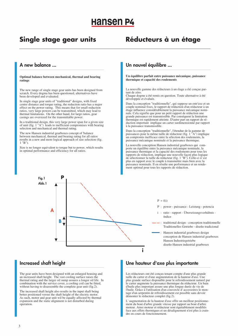
In single stage gear units of "traditional" designs, with fixedcentre distance and torque rating, the reduction ratio has a majoreffect on the power rating. This means that for small reductionratios, very large powers can be transmitted, which may lead tothermal limitations. On the other hand, for large ratios, gearcasings are oversized for the transmittable power.
In a traditional design, this very large power span for a given sizeof unit (fig. 1 "A") leads to inefficient compromises with bearingselection and mechanical and thermal rating.
The new Hansen industrial gearboxes concept of 'balancebetween mechanical, thermal and bearing rating for all ratiosresults in a new and more logical approach of size selection (fig.1 "B").
Size is no longer equivalent to torque but to power, which resultsin optimal performance and efficiency for all ratios.
Single stage gear units Réducteurs à un étage
Une hauteur d'axe plus importante
Les réducteurs ont été conçus tenant compte d'une plus grandetaille du carter et d'une augmentation de la hauteur d'axe. Uneplus grande surface disponible pour le refroidissement naturel parle carter augmente la puissance thermique du réducteur. Un baind'huile plus important assure une plus longue durée de vie del'huile. Grâce à l'utilisation d'un couvercle d' accessoires le mon-tage d'un serpentin de refroidissement est possible sans devoirdémonter le réducteur complet (fig.2).
L' augmentation de la hauteur d'axe offre un meilleur positionne-ment du bout d'arbre grande vitesse par rapport au bout d'arbremoteur. Ainsi moteur et réducteur sont équitablement modifiésface aux effets thermiques et un désalignement n'est plus à crain-dre en cours de fonctionnement.
ansen
B
A
i
P = f(i)
P : power - puissance - Leistung - potencia
i : ratio - rapport - Übersetzungsverhältnis - índice
: traditional design - conception traditionnelle Traditionelles Getriebe - diseño tradicional
: Hansen industrial gearboxes designconception de Hansen industrial gearboxesHansen Industriegetriebediseño Hansen industrial gearboxes
Fig.1
Abb.1
3
P
Page 1

ansen Reductores de una etapa
Un nuevo equilibrio ...
Equilibrio perfecto entre las potencias mécanicas y térmicasde los reductores y la capacidad de carga de los rodamientos
La nueva gama de reductores de una etapa ha sido diseñada apartir de cero. Cada dogma ha sido cuestionado de nuevo,soluciones alternativas han sido desarolladas y evaluadas.
En los diseños convencionales donde la distancia entre centros yel par son fijos, el índice de reducción del reductor de una etapaafecta considerablemente la potencia mecánica. Lo que significaque los reductores con indices pequeños permiten la transmisiónde potencias muy importantes alcanzando su límite de potenciatérmica muy rapidamente. Por otro lado para los indices mayores, las carcasas estánsobredimensionadas para la potencia transmisible.
Asimismo, en los diseños convencionales, el amplio rango depotencias para un tamaño determinado (ver fig. 1 “A”) implicaun compromiso ineficaz en cuanto a selección de rodamientos ypotencia mecánica y térmica.
El nuevo concepto Hansen industrial gearboxes basado en elequilibrio entre la potencia mecánica y térmica de los reductoresy la capacidad de carga de los rodamientos implica una nuevaaproximación más lógica acerca de la seleción del tamaño de losreductores (fig. 1 "B")
El tamaño ya no está relacionado con el par sino con la potenciaresultando en una capacidad y un rendimiento optimo para todoslos índices.
Einstufige Getriebe
Mayor entreeje
Los reductores están diseñados con carcasas alargadas y los ejesestán colocados en una posición más elevada. El mayorsuperficie aumenta la potencia térmica y el baño de aceite másamplio asegura una vida útil más larga del aceite.
En los reductores dotados de una tapa auxiliar, se puede montarun serpentín de refrigeración sin necesidad de desmontar el re-ductor (fig.2).
La posición más alta del eje permite un mejor posicionamientodel reductor con respecto al eje del motor eléctrico. Así laexpansión térmica afecta de igual manera el motor y el reductor yla alineación estática no varía en funcionamiento.
Neue Ausgewogenheit …
Optimale Balance zwischen mechanischen, thermischen undLager-Belastungen
Die neue Baureihe einstufiger Getriebe basiert auf einergrundlegend neuen Konstruktion. Produktanforderungen wurdeninnovativ umgesetzt und die neusten Erkenntnisse der Forschungund Entwicklung integriert.
Die Nennleistung eines einstufigen Getriebes wird bei"traditionellen" Konstruktionen mit festem Achsabstand undNenndrehmoment sehr stark durch das Übersetzungsverhältnisbeeinflußt. Bei kleinen Übersetzungen können hohe Leistungenübertragen werden, die aber durch die Wärmeentwicklungbegrenzt werden. Im Verhältnis zur übertragenen Leistung fallenbei großen Übersetzungen die Getriebegehäuse dagegen relativgroß aus.
Bei der herkömmlichen Konstruktion eines Getriebes (Abb. 1"A") führt diese sehr große Leistungsspanne zu ineffizientenKompromißlösungen bei der Lagerauswahl sowie bei dermechanischen und thermischen Belastbarkeit.
Das neue Hansen Industriegetriebe-Konzept der "Balancezwischen mechanischen, thermischen und Lager-Belastungen"umfaßt alle Übersetzungen und führt bei der Größenauswahl(Abb. 1 "B") zu einem grundlegend neuen Lösungsansatz.
Die Getriebegröße ist nicht mehr gleichbedeutend mit demDrehmoment, sondern mit der Leistung. Daraus resultieren einLeistungs- und Wirkungsgradoptimum für sämtlicheÜbersetzungsverhältnisse.
Erhöhte Position der Welle
Die Getriebe haben ein größeres Gehäuse und eine größereAchshöhe. Durch die zur Verfügung stehende Oberfläche ist einehohe Wärmeabfuhr und damit eine hohe thermische Belastungmöglich. Das größere Ölbad garantiert eine lange Standzeit desÖls. In Verbindung mit der Serviceöffnung kann eineKühlschlange montiert werden, ohne das komplette Getriebedabei zerlegen zu müssen (Abb.2).
Aufgrund der größeren Achshöhe ist eine günstige Positionierungder Antriebswelle zum Motor gegeben. In dieser Anordnungwerden Motor und Getriebe gleichermaßen von derWärmeausdehnung beeinflußt sowie die statische Ausrichtungwährend des Betriebs nicht beeinträchtigt.
4
Fig.2
Abb.2
Page 1
Solutions flexibles
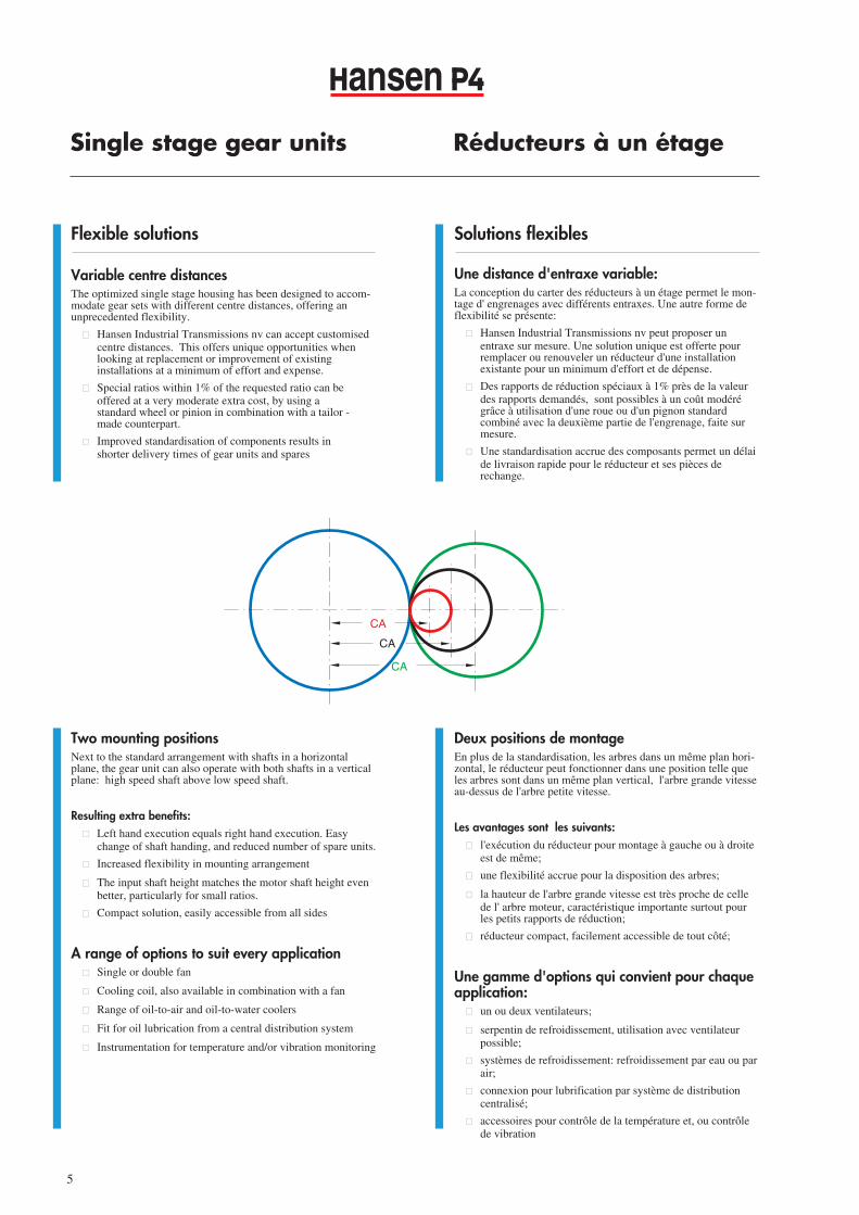
Une distance d'entraxe variable:La conception du carter des réducteurs à un étage permet le mon-tage d' engrenages avec différents entraxes. Une autre forme deflexibilité se présente:
� Hansen Industrial Transmissions nv peut proposer un entraxe sur mesure. Une solution unique est offerte pour remplacer ou renouveler un réducteur d'une installation existante pour un minimum d'effort et de dépense.
� Des rapports de réduction spéciaux à 1% près de la valeur des rapports demandés, sont possibles à un coût modéré grâce à utilisation d'une roue ou d'un pignon standard combiné avec la deuxième partie de l'engrenage, faite sur mesure.
� Une standardisation accrue des composants permet un délaide livraison rapide pour le réducteur et ses pièces de rechange.
Flexible solutions
Variable centre distancesThe optimized single stage housing has been designed to accom-modate gear sets with different centre distances, offering anunprecedented flexibility.
� Hansen Industrial Transmissions nv can accept customised centre distances. This offers unique opportunities when looking at replacement or improvement of existing installations at a minimum of effort and expense.
� Special ratios within 1% of the requested ratio can be offered at a very moderate extra cost, by using a standard wheel or pinion in combination with a tailor -made counterpart.
� Improved standardisation of components results in shorter delivery times of gear units and spares
Single stage gear units Réducteurs à un étage
ansen
5
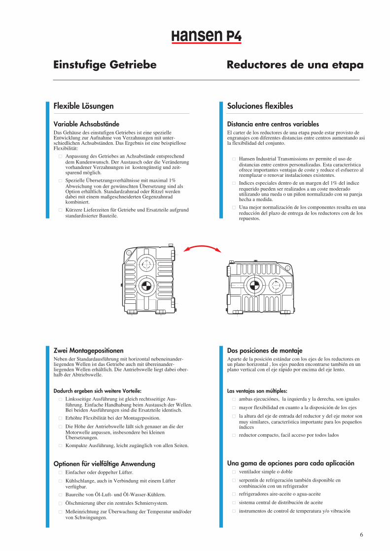
Two mounting positionsNext to the standard arrangement with shafts in a horizontal plane, the gear unit can also operate with both shafts in a verticalplane: high speed shaft above low speed shaft.
Resulting extra benefits: � Left hand execution equals right hand execution. Easy
change of shaft handing, and reduced number of spare units.
� Increased flexibility in mounting arrangement
� The input shaft height matches the motor shaft height even better, particularly for small ratios.
� Compact solution, easily accessible from all sides
A range of options to suit every application� Single or double fan
� Cooling coil, also available in combination with a fan
� Range of oil-to-air and oil-to-water coolers
� Fit for oil lubrication from a central distribution system
� Instrumentation for temperature and/or vibration monitoring
Deux positions de montageEn plus de la standardisation, les arbres dans un même plan hori-zontal, le réducteur peut fonctionner dans une position telle queles arbres sont dans un même plan vertical, l'arbre grande vitesseau-dessus de l'arbre petite vitesse.
Les avantages sont les suivants:� l'exécution du réducteur pour montage à gauche ou à droite
est de même;
� une flexibilité accrue pour la disposition des arbres;
� la hauteur de l'arbre grande vitesse est très proche de celle de l' arbre moteur, caractéristique importante surtout pour les petits rapports de réduction;
� réducteur compact, facilement accessible de tout côté;
Une gamme d'options qui convient pour chaqueapplication:
� un ou deux ventilateurs;
� serpentin de refroidissement, utilisation avec ventilateurpossible;
� systèmes de refroidissement: refroidissement par eau ou parair;
� connexion pour lubrification par système de distribution centralisé;
� accessoires pour contrôle de la température et, ou contrôle de vibration
CA
CA
CA
Page 1
ansen Reductores de una etapa
Soluciones flexibles
Distancia entre centros variablesEl carter de los reductores de una etapa puede estar provisto deengranajes con diferentes distancias entre centros aumentando asila flexibilidad del conjunto.
� Hansen Industrial Transmissions nv permite el uso de distancias entre centros personalizadas. Esta característica ofrece importantes ventajas de coste y reduce el esfuerzo al reemplazar o renovar instalaciones existentes.
� Indices especiales dentro de un margen del 1% del indice requerido pueden ser realizados a un coste moderado utilizando una rueda o un piñon normalizado con su pareja hecha a medida.
� Una mejor normalización de los componentes resulta en una reducción del plazo de entrega de los reductores con de los repuestos.
Einstufige Getriebe
Flexible Lösungen
Variable AchsabständeDas Gehäuse des einstufigen Getriebes ist eine spezielleEntwicklung zur Aufnahme von Verzahnungen mit unter-schiedlichen Achsabständen. Das Ergebnis ist eine beispielloseFlexibilität:
� Anpassung des Getriebes an Achsabstände entsprechenddem Kundenwunsch. Der Austausch oder die Veränderung vorhandener Verzahnungen ist kostengünstig und zeit-sparend möglich.
� Spezielle Übersetzungsverhältnisse mit maximal 1% Abweichung von der gewünschten Übersetzung sind als Option erhältlich. Standardzahnrad oder Ritzel werden dabei mit einem maßgeschneiderten Gegenzahnrad kombiniert.
� Kürzere Lieferzeiten für Getriebe und Ersatzteile aufgrund standardisierter Bauteile.
6
Zwei MontagepositionenNeben der Standardausführung mit horizontal nebeneinander-liegenden Wellen ist das Getriebe auch mit übereinander-liegenden Wellen erhältlich. Die Antriebswelle liegt dabei ober-halb der Abtriebswelle.
Dadurch ergeben sich weitere Vorteile: � Linksseitige Ausführung ist gleich rechtsseitige Aus-
führung. Einfache Handhabung beim Austausch der Wellen.Bei beiden Ausführungen sind die Ersatzteile identisch.
� Erhöhte Flexibilität bei der Montageposition.
� Die Höhe der Antriebswelle läßt sich genauer an die der Motorwelle anpassen, insbesondere bei kleinen Übersetzungen.
� Kompakte Ausführung, leicht zugänglich von allen Seiten.
Optionen für vielfältige Anwendung� Einfacher oder doppelter Lüfter.
� Kühlschlange, auch in Verbindung mit einem Lüfter verfügbar.
� Baureihe von Öl-Luft- und Öl-Wasser-Kühlern.
� Ölschmierung über ein zentrales Schmiersystem.
� Meßeinrichtung zur Überwachung der Temperatur und/oder von Schwingungen.
Dos posiciones de montajeAparte de la posición estándar con los ejes de los reductores enun plano horizontal , los ejes pueden encontrarse también en unplano vertical con el eje rápido por encima del eje lento.
Las ventajas son múltiples:� ambas ejecuciónes, la izquierda y la derecha, son iguales
� mayor flexibilidad en cuanto a la disposición de los ejes
� la altura del eje de entrada del reductor y del eje motor son muy similares, característica importante para los pequeños índices
� reductor compacto, facil acceso por todos lados
Una gama de opciones para cada aplicación� ventilador simple o doble
� serpentín de refrigeración también disponible en combinación con un refrigerador
� refrigeradores aire-aceite o agua-aceite
� sistema central de distribución de aceite
� instrumentos de control de temperatura y/o vibración
Page 1
Solutions efficaces
Haute performance grâce à la géométrie d'engrenages
La transmission d'une haute puissance mécanique par un réduc-teur à un étage exige un service uniforme du réducteur. Une macro-géométrie spécifique des engrenages est introduitepour obtenir une réduction des pertes de puissance, un bruit ré-duit et de faibles vibrations. Cela contribue à un service sûr etécologique.
La réduction du coût opérationnel grâce à une augmentation durendement, influence favorablement et dépasse même le coût del'investissement d' un réducteur.
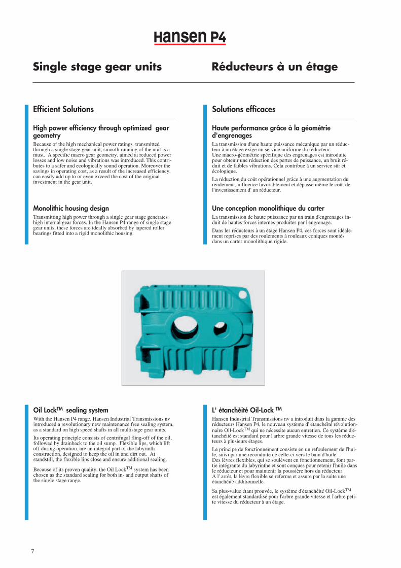
Une conception monolithique du carterLa transmission de haute puissance par un train d'engrenages in-duit de hautes forces internes produites par l'engrenage.
Dans les réducteurs à un étage Hansen P4, ces forces sont idéale-ment reprises par des roulements à rouleaux coniques montésdans un carter monolithique rigide.
Efficient Solutions
High power efficiency through optimized geargeometryBecause of the high mechanical power ratings transmittedthrough a single stage gear unit, smooth running of the unit is amust. A specific macro gear geometry, aimed at reduced powerlosses and low noise and vibrations was introduced. This contri-butes to a safer and ecologically sound operation. Moreover thesavings in operating cost, as a result of the increased efficiency,can easily add up to or even exceed the cost of the originalinvestment in the gear unit.
Monolithic housing designTransmitting high power through a single gear stage generateshigh internal gear forces. In the Hansen P4 range of single stagegear units, these forces are ideally absorbed by tapered rollerbearings fitted into a rigid monolithic housing.
Single stage gear units Réducteurs à un étage
ansen
7
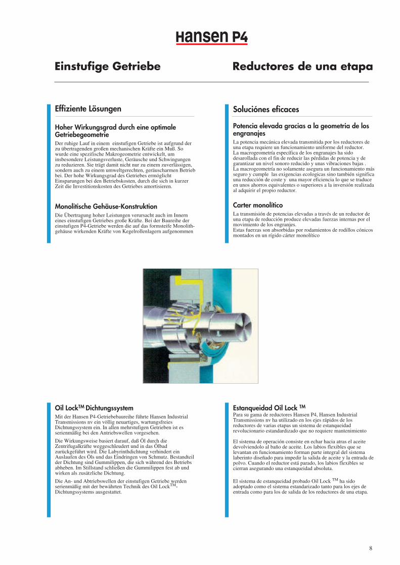
Oil LockTM sealing systemWith the Hansen P4 range, Hansen Industrial Transmissions nvintroduced a revolutionary new maintenance free sealing system,as a standard on high speed shafts in all multistage gear units.
Its operating principle consists of centrifugal fling-off of the oil,followed by drainback to the oil sump. Flexible lips, which liftoff during operation, are an integral part of the labyrinthconstruction, designed to keep the oil in and dirt out. Atstandstill, the flexible lips close and ensure additional sealing.
Because of its proven quality, the Oil LockTM system has beenchosen as the standard sealing for both in- and output shafts ofthe single stage range.
L' étanchéité Oil-Lock TM
Hansen Industrial Transmissions nv a introduit dans la gamme desréducteurs Hansen P4, le nouveau système d' étanchéité révolution-naire Oil-LockTM qui ne nécessite aucun entretien. Ce système d'é-tanchéité est standard pour l'arbre grande vitesse de tous les réduc-teurs à plusieurs étages.
Le principe de fonctionnement consiste en un refoulement de l'hui-le, suivi par une reconduite de celle-ci vers le bain d'huile. Des lèvres flexibles, qui se soulèvent en fonctionnement, font par-tie intégrante du labyrinthe et sont conçues pour retenir l'huile dansle réducteur et pour maintenir la poussière hors du réducteur. A l' arrêt, la lèvre flexible se referme et assure par la suite uneétanchéité additionnelle.
Sa plus-value étant prouvée, le système d'étanchéité Oil-LockTM
est également standardisé pour l'arbre grande vitesse et l'arbre peti-te vitesse du réducteur à un étage.
Page 1
ansen Reductores de una etapa
Soluciónes eficaces
Potencia elevada gracias a la geometria de losengranajesLa potencia mecánica elevada transmitida por los reductores deuna etapa requiere un funcionamiento uniforme del reductor.La macrogeometría específica de los engranajes ha sidodesarollada con el fin de reducir las pérdidas de potencia y degarantizar un nivel sonoro reducido y unas vibraciones bajas .La macrogeometría no solamente asegura un funcionamiento másseguro y cumple las exigencias ecologicas sino también significauna reducción de coste y una mayor eficiencia lo que se traduceen unos ahorros equivalentes o superiores a la inversión realizadaal adquirir el propio reductor.
Carter monolíticoLa transmisión de potencias elevadas a través de un reductor deuna etapa de reducción produce elevadas fuerzas internas por elmovimiento de los engranjes. Estas fuerzas son absorbidas por rodamientos de rodillos cónicosmontados en un rígido cárter monolítico
Einstufige Getriebe
Effiziente Lösungen
Hoher Wirkungsgrad durch eine optimaleGetriebegeometrieDer ruhige Lauf in einem einstufigen Getriebe ist aufgrund derzu übertragenden großen mechanischen Kräfte ein Muß. Sowurde eine spezifische Makrogeometrie entwickelt, uminsbesondere Leistungsverluste, Geräusche und Schwingungenzu reduzieren. Sie trägt damit nicht nur zu einem zuverlässigen,sondern auch zu einem umweltgerechten, geräuscharmen Betriebbei. Der hohe Wirkungsgrad des Getriebes ermöglichtEinsparungen bei den Betriebskosten, durch die sich in kurzerZeit die Investitionskosten des Getriebes amortisieren.
Monolitische Gehäuse-KonstruktionDie Übertragung hoher Leistungen verursacht auch im Innerneines einstufigen Getriebes große Kräfte. Bei der Baureihe dereinstufigen P4-Getriebe werden die auf das formsteife Monolith-gehäuse wirkenden Kräfte von Kegelrollenlagern aufgenommen
8
Estanqueidad Oil Lock TM
Para su gama de reductores Hansen P4, Hansen IndustrialTransmissions nv ha utilizado en los ejes rápidos de losreductores de varias etapas un sistema de estanqueidadrevolucionario estandardizado que no requiere mantenimiento
El sistema de operación consiste en echar hacia atras el aceitedevolviendolo al baño de aceite. Los labios flexibles que selevantan en funcionamiento forman parte integral del sistemalaberinto diseñado para impedir la salida de aceite y la entrada depolvo. Cuando el reductor está parado, los labios flexibles secierran asegurando una estanqueidad absoluta.
El sistema de estanqueidad probado Oil Lock TM ha sidoadoptado como el sistema estandarizado tanto para los ejes deentrada como para los de salida de los reductores de una etapa.
Oil LockTM DichtungssystemMit der Hansen P4-Getriebebaureihe führte Hansen IndustrialTransmissions nv ein völlig neuartiges, wartungsfreiesDichtungssystem ein. In allen mehrstufigen Getrieben ist esserienmäßig bei den Antriebswellen vorgesehen.
Die Wirkungsweise basiert darauf, daß Öl durch dieZentrifugalkräfte weggeschleudert und in das Ölbadzurückgeführt wird. Die Labyrinthdichtung verhindert einAuslaufen des Öls und das Eindringen von Schmutz. Bestandteilder Dichtung sind Gummilippen, die sich während des Betriebsabheben. Im Stillstand schließen die Gummilippen fest ab undwirken als zusätzliche Dichtung.
Die An- und Abtriebswellen der einstufigen Getriebe werdenserienmäßig mit der bewährten Technik des Oil LockTM-Dichtungssystems ausgestattet.
Page 1
Qualité accrue
Facilité pour l'entretien
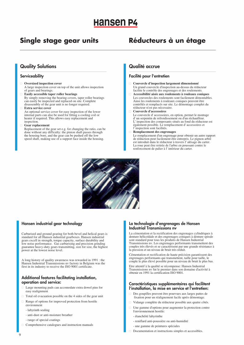
� Couvercle d'inspection largement dimensionnéUn grand couvercle d'inspection au-dessus du réducteur facilite le contrôle des engrenages et des roulements.
� Accessibilité aisée aux roulements à rouleaux coniquesLes couvercles des roulements sont facilement démontables. Ainsi les roulements à rouleaux coniques peuvent être contrôlés et remplacés sur site. Le démontage complet du réducteur n'est pas nécessaire.
� Couvercle d'accessoiresLe couvercle d' accessoires, en option, permet le montage d' un serpentin de refroidissement ou d'un réchauffeur. L' inspection des composants situés au fond du réducteur est également possible. Le remplacement d' accessoires et l' inspection sont facilités.
� Remplacement des engrenagesLe remplacement d'un engrenage pour obtenir un autre rapportde réduction peut facilement être entrepris. Le pignon arbré est introduit dans le réducteur à travers l' alésage du carter.La roue peut être retirée de l'arbre en poussant contre le renforcement de palier à l' intérieur du carter.
Quality Solutions
Serviceability
� Oversized inspection coverA large inspection cover on top of the unit allows inspection of gears and bearings.
� Easily accessible taper roller bearingsBy simply removing the bearing covers, taper roller bearings can easily be inspected and replaced on site. Complete disassembly of the gear unit is no longer required.
� Extra service coverAn optional service cover for easy inspection of the lower internal parts can also be used for fitting a cooling coil or heater if required. This allows easy replacement andinspection.
� Gear replacementReplacement of the gear set e.g. for changing the ratio, can be done without any difficulty: the pinion shaft passes through the housing bore, and the gear can be pushed off the low speed shaft, making use of a support face inside the housing.
Single stage gear units Réducteurs à un étage
ansen
La technologie d'engrenages de HansenIndustrial Transmissions nvLa cémentation et la rectification des engrenages cylindriques àdenture hélicoïdale et des engrenages coniques à denture spiralesont standard pour tous les produits de Hansen IndustrialTransmissions nv. Les engrenages performants transmettent descouples très élevés et se caractérisent par une grande résistance àla pression et un niveau de bruit très réduit.
Cémentation et rectification de haute précision garantissent desengrenages performants qui transmettent, taille pour taille, lecouple le plus élevé possible pour un niveau de bruit le plus bas.
Etre attentif à la qualité se récompense: Hansen IndustrialTransmissions nv fut le premier dans son domaine d'activité àobtenir en 1991 la certification ISO 9001.
Caractéristiques supplémentaires qui facilitentl'installation, la mise en service et l'entretien:� Des goupilles peuvent être pourvues aux larges pattes de
fixation pour un réalignement facile après démontage.
� Vidange complète du réducteur possible aux quatre côtés.
� Une gamme d'options pour augmenter la protection contre l'environnement hostile:
- étanchéité labyrinthe
- reniflard anti-poussière ou anti-humidité
- une gamme de peintures spéciales
� Documentation et instructions simples et accessibles.
Hansen industrial gear technology
Carburised and ground gearing for both bevel and helical gears isstandard for all Hansen industrial gearboxes. Hansen industrialgears excell in strength, torque capacity, surface durability andlow noise performance. Gas carburising and precision grindingguarantee heavy-duty gears transmitting, size for size, the highestpower at the lowest noise level.
A long history of quality awareness was rewarded in 1991 : theHansen Industrial Transmissions nv factory in Belgium was thefirst in its industry to receive the ISO 9001 certificate.
Additional features facilitating installation,operation and service:� Large mounting pads can accomodate extra dowel pins for
easy realignment
� Total oil evacuation possible on the 4 sides of the gear unit
� Range of options for improved protection from hostile environment
- labyrinth sealing
- anti-dust or anti-moisture breather
- range of special coatings
� Comprehensive catalogues and instruction manuals
9
Page 1
ansen Reductores de una etapa
Facilidad de mantenimiento
Tapa de inspección de gran tamaño
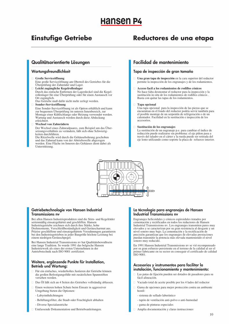
� Una gran tapa de inspección en la cara superior del reductor permite la inspección de los engranajes y de los rodamientos.
� Acceso facil a los rodamientos de rodillos cónicosNo hace falta desmontar el reductor para la inspección y la sustitución in-situ de los rodamientos de rodillos cónicos . Basta con quitar las tapas de los rodamientos.
� Tapa opcionalUna tapa opcional para la inspección de las piezas que se encuentran en el fondo del reductor podría servir también para el posible montaje de un serpentín de refrigeración o de un calentador. Facilidad en la sustitución e inspección de los accesorios.
� Sustitución de los engranajesLa sustitución de un engranaje p.e. para cambiar el índice de reducción puede realizarse sin problema: el eje piñon pasa a través del taladro en el cárter y la rueda puede ser retirada del eje lento utilizando como soporte la placa de refuerzo interior.
Einstufige Getriebe
Qualitätsorientierte Lösungen
Wartungsfreundlichkeit
� Große ServiceöffnungEine große Serviceöffnung am Oberteil des Getriebes für die
Überprüfung der Zahnräder und Lager.� Leicht zugängliche Kegelrollenlager
Durch das einfache Entfernen der Lagerdeckel sind die Kegel-rollenlager für eine Überprüfung oder für einen Austausch vor Ort zugänglich. Das Getriebe muß dafür nicht mehr zerlegt werden.
� Sonder-ServiceöffnungEine Sonder-Serviceöffnung ist als Option erhältlich und kann zur bequemen Überprüfung im unteren Innenbereich, zur Montage einer Kühlschlange oder Heizung verwendet werden. Wartung und Austausch werden durch diese Abdeckung erleichtert.
� Wechsel von ZahnrädernDer Wechsel eines Zahnradpaares, zum Beispiel um das Über-setzungsverhältnis zu verändern, läßt sich ohne Schwierig-keiten durchführen.
Die Ritzelwelle wird durch die Gehäusebohrung geschoben und das Zahnrad kann von der Abtriebswelle abgezogen werden. Eine Fläche im Inneren des Gehäuses dient dabei als Unterstützung.
La técnología para engranajes de HansenIndustrial Transmissions nvEngranajes helicoidales y cónicos espiroidales tratados porcementación y rectificados en todos los reductores de HansenIndustrial Transmissions nv. Los engranajes transmiten pares muyelevados y se caracterizan por su gran resistencia al desgaste y unnivel sonoro muy bajo. La cementación y la rectificación deprecisión garantizan que los engranajes de elevadas prestacionespuedan transmitir la potencia más elevada manteniendo el nivelsonoro muy reducido.
En 1991 Hansen Industrial Transmissions nv se vió recompensadopor su gran esfuerzo persistente en el terreno de la calidad al ser elprimer fabricante en su sector en conseguir el certificado de calidadISO 9001.
Accesorios y instrumentos para facilitar lainstalación, funcionamiento y mantenimiento:� Las patas de fijación pueden ser dotados de pasadores para su
fácil alineación.
� Vaciado total de aceite posible por los 4 lados del reductor
� Gama de opciones para mejor protección contra un ambiente hostil:
- sistema de sellado laberíntico
- tapón de ventilación anti-polvo o anti-humedad
- gama de pinturas especiales
� Amplia documentación y claras instrucciones
Getriebetechnologie von Hansen IndustrialTransmissions nvBei allen Hansen Industrieprodukten sind die Stirn- und Kegelräderserienmäßig einsatzgehärtet und geschliffen. HansenIndustriegetriebe zeichnen sich durch ihre Stärke, hoheDrehmomente, Verschleißbeständigkeit und Geräuscharmut aus.Präzise geschliffene und einsatzgehärtete Verzahnungen garantierenbei den Industriegetrieben in jeder Baugröße höchste Leistung beieinem niedrigen Geräuschpegel.
Bei Hansen Industrial Transmissions nv hat Qualtitätsbewußtseineine lange Tradition. So wurde 1991 das belgische HansenIndustriewerk als eines der ersten Unternehmen in derAntriebstechnik nach ISO 9001 zertifiziert.
Weitere, ergänzende Punkte für Installation,Betrieb und Wartung:� Für ein einfaches, wiederholtes Justieren der Getriebe können
die großen Befestigungsfüße mit zusätzlichen Spannstiften versehen werden.
� Das Öl läßt sich an 4 Seiten des Getriebes vollständig ablassen.
� Einen weiteren hohen Schutz beim Einsatz in aggressiver Umgebung bieten die Optionen:
- Labyrinthdichtungen
- Belüftungsfilter, die Staub oder Feuchtigkeit abhalten
- Diverse Spezialanstriche
� Umfassende Dokumentation und Betriebsanleitungen.
10
Page 1
Product Gamme Produkt- Gama derange de produits palette productos
11
ansen
1.2 1.25 1.4 1.6 1.8 2 2.24 2.5 2.8 3.15 3.55 4 4.5 5 5.6
00
500500
10001000
15001500
20002000
25002500
30003000
35003500
40004000
45004500
50005000
P (
kW
) n
1 =
15
00 m
in-1
G
F
E
D
C
SizesTailles BaugrößenTamaños
Mechanical Puissance méca- Mechanische Potencia mecá-power rating nique nominale Leistung nica nominal
Nominal ratio - Rapport nominal - Nennübersetzung - Índice nominal
QHP.1
QHP.1W
Page 1
English E
Français F
Deutsch D
Español S
A
ansen
E
Pagina: 1
GEAR UNIT STANDARD ACCESSORIES AND OPTIONS
OIL-LOCKTM
t°
1
2
4Option
3Option
5
6Option
t°
7Option
8Option
10Option
8 Option7Option 6
Option
5
2
1
11
13 Option
15
16
18191112Option13Option
20Option 20Option
10Option
t°���
����
���
��
��
��
���
�
��
�
��
�����
�
�
�
�
�
����
��
�
�
14
12 Option
4Option
3Option
Option
Option Option
Option
9Option
Option
17
ansen
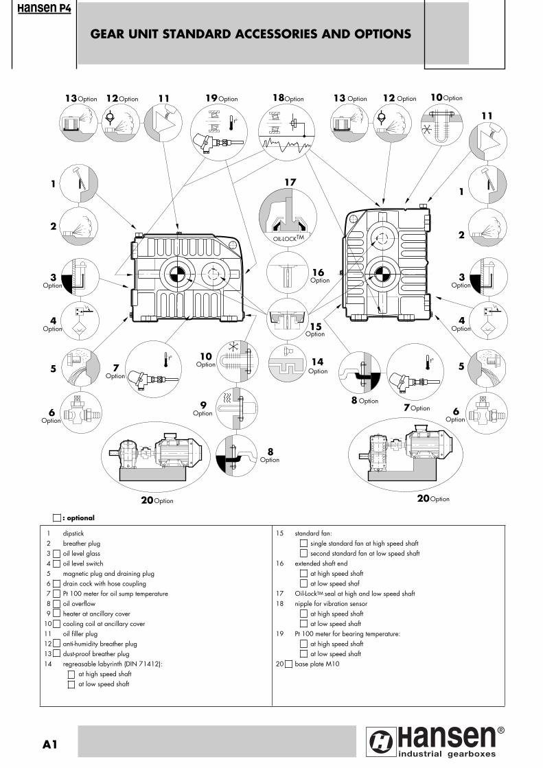
1 dipstick2 breather plug 3 oil level glass 4 oil level switch5 magnetic plug and draining plug6 drain cock with hose coupling7 Pt 100 meter for oil sump temperature8 oil overflow9 heater at ancillary cover
10 cooling coil at ancillary cover11 oil filler plug12 anti-humidity breather plug13 dust-proof breather plug14 regreasable labyrinth (DIN 71412):
at high speed shaft at low speed shaft
15 standard fan:single standard fan at high speed shaft second standard fan at low speed shaft
16 extended shaft endat high speed shaftat low speed shaf
17 Oil-LockTM seal at high and low speed shaft 18 nipple for vibration sensor
at high speed shaft at low speed shaft
19 Pt 100 meter for bearing temperature:at high speed shaft at low speed shaft
20 base plate M10
: optional
A1
Pagina: 1
Page
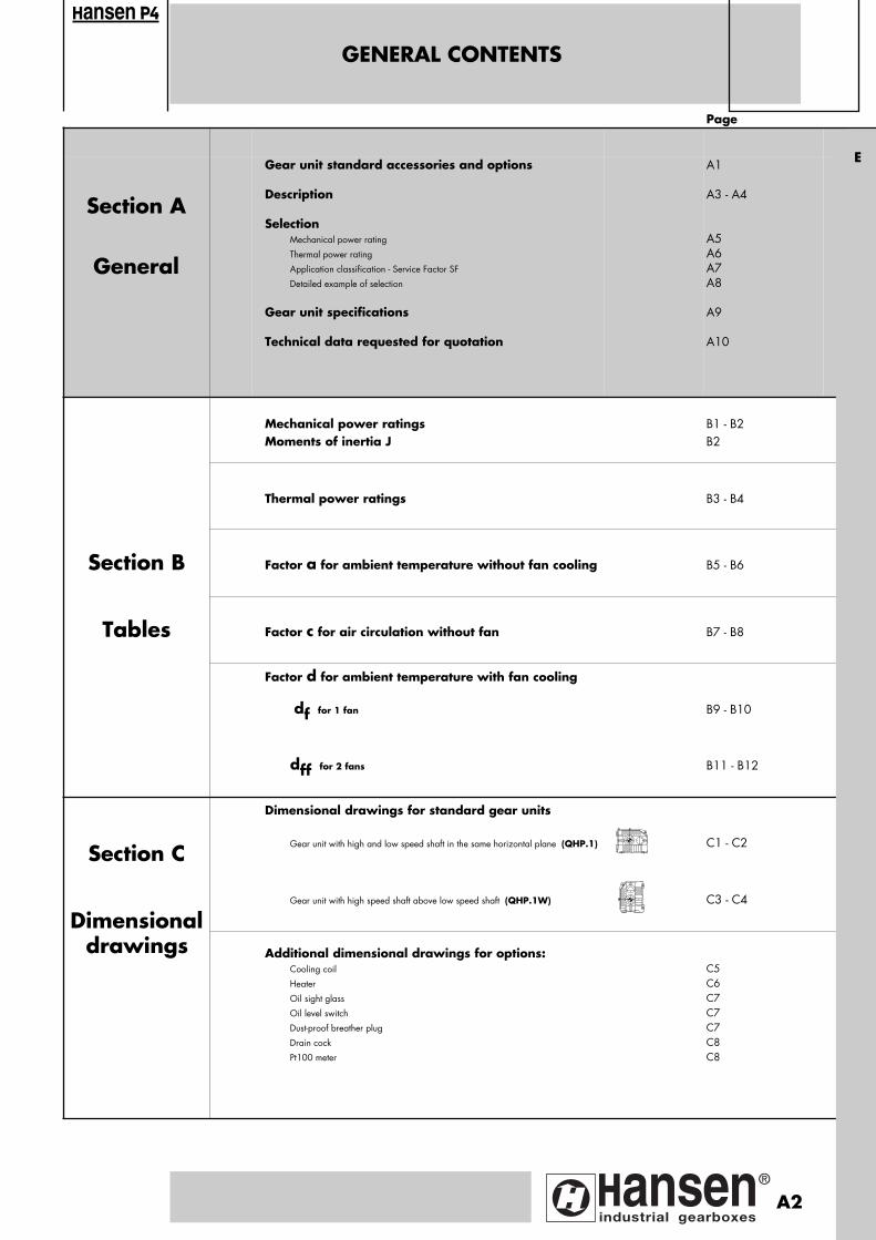
Section A
General
Gear unit standard accessories and options
Description
SelectionMechanical power rating
Thermal power rating
Application classification - Service Factor SF
Detailed example of selection
Gear unit specifications
Technical data requested for quotation
A1
A3 - A4
A5 A6A7A8
A9
A10
Mechanical power ratingsMoments of inertia J
B1 - B2B2
Thermal power ratings B3 - B4
Section B Factor a for ambient temperature without fan cooling B5 - B6
Tables Factor c for air circulation without fan B7 - B8
Factor d for ambient temperature with fan cooling
df for 1 fan B9 - B10
dff for 2 fans B11 - B12
Section C
Dimensional drawings for standard gear units
Gear unit with high and low speed shaft in the same horizontal plane (QHP.1) C1 - C2
DimensionalGear unit with high speed shaft above low speed shaft (QHP.1W) C3 - C4
drawings
Additional dimensional drawings for options: Cooling coil
Heater
Oil sight glass
Oil level switch
Dust-proof breather plug
Drain cock
Pt100 meter
C5C6C7C7C7C8C8
GENERAL CONTENTS
ansen
E
A2
Pagina: 1
DESCRIPTION
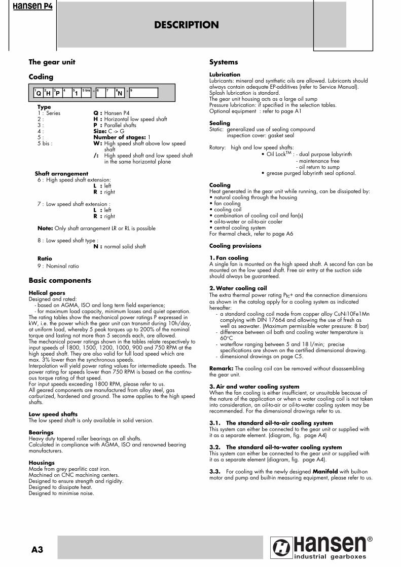
The gear unit
Coding
Type1 : Series Q : Hansen P42 : H : Horizontal low speed shaft3 : P : Parallel shafts4 : Size: C -> G5 : Number of stages: 15 bis : W: High speed shaft above low speed
shaft/: High speed shaft and low speed shaft
in the same horizontal plane
Shaft arrangement 6 : High speed shaft extension:
L : leftR : right
7 : Low speed shaft extension :L : leftR : right
Note: Only shaft arrangement LR or RL is possible
8 : Low speed shaft type :N : normal solid shaft
Ratio9 : Nominal ratio
Basic components
Helical gearsDesigned and rated:
- based on AGMA, ISO and long term field experience; - for maximum load capacity, minimum losses and quiet operation.
The rating tables show the mechanical power ratings P expressed inkW, i.e. the power which the gear unit can transmit during 10h/day,at uniform load, whereby 5 peak torques up to 200% of the nominaltorque and lasting not more than 5 seconds each, are allowed.The mechanical power ratings shown in the tables relate respectively toinput speeds of 1800, 1500, 1200, 1000, 900 and 750 RPM at thehigh speed shaft. They are also valid for full load speed which aremax. 3% lower than the synchronous speeds.Interpolation will yield power rating values for intermediate speeds. Thepower rating for speeds lower than 750 RPM is based on the continu-ous torque rating of that speed.For input speeds exceeding 1800 RPM, please refer to us.All geared components are manufactured from alloy steel, gas carburized, hardened and ground. The same applies to the high speedshafts.
Low speed shaftsThe low speed shaft is only available in solid version.
BearingsHeavy duty tapered roller bearings on all shafts.Calculated in compliance with AGMA, ISO and renowned bearingmanufacturers.
HousingsMade from grey pearlitic cast iron.Machined on CNC machining centers.Designed to ensure strength and rigidity.Designed to dissipate heat.Designed to minimise noise.
Systems
LubricationLubricants: mineral and synthetic oils are allowed. Lubricants shouldalways contain adequate EP-additives (refer to Service Manual).Splash lubrication is standard. The gear unit housing acts as a large oil sumpPressure lubrication: if specified in the selection tables.Optional equipment : refer to page A1
SealingStatic: generalized use of sealing compound
inspection cover: gasket seal
Rotary: high and low speed shafts:• Oil LockTM : - dual purpose labyrinth
- maintenance free- oil return to sump
• grease purged labyrinth seal optional.
Cooling Heat generated in the gear unit while running, can be dissipated by:• natural cooling through the housing• fan cooling• cooling coil• combination of cooling coil and fan(s)• oil-to-water or oil-to-air cooler• central cooling systemFor thermal check, refer to page A6
Cooling provisions
1. Fan coolingA single fan is mounted on the high speed shaft. A second fan can bemounted on the low speed shaft. Free air entry at the suction sideshould always be guaranteed.
2. Water cooling coilThe extra thermal power rating Ptc+ and the connection dimensionsas shown in the catalog apply for a cooling system as indicatedhereafter:
- a standard cooling coil made from copper alloy CuNi10Fe1Mn complying with DIN 17664 and allowing the use of fresh as well as seawater. (Maximum permissible water pressure: 8 bar)
- difference between oil bath and cooling water temperature is 60°C
- waterflow ranging between 5 and 18 l/min; precise specifications are shown on the certified dimensional drawing.
- dimensional drawings on page C5.
Remark: The cooling coil can be removed without disassemblingthe gear unit.
3. Air and water cooling systemWhen the fan cooling is either insufficient, or unsuitable because ofthe nature of the application or when a water cooling coil is not takeninto consideration, an oil-to-air or oil-to-water cooling system may berecommended. For the dimensional drawings refer to us.
3.1. The standard oil-to-air cooling systemThis system can either be connected to the gear unit or supplied withit as a separate element. (diagram, fig. page A4)
3.2. The standard oil-to-water cooling systemThis system can either be connected to the gear unit or supplied withit as a separate element (diagram, fig. page A4).
3.3. For cooling with the newly designed Manifold with built-onmotor and pump and built-in measuring equipment, please refer to us.
1Q
2H
3P
4 51
5 bis - 6 7 8N - 9
ansen
A3
Pagina: 1
DESCRIPTION
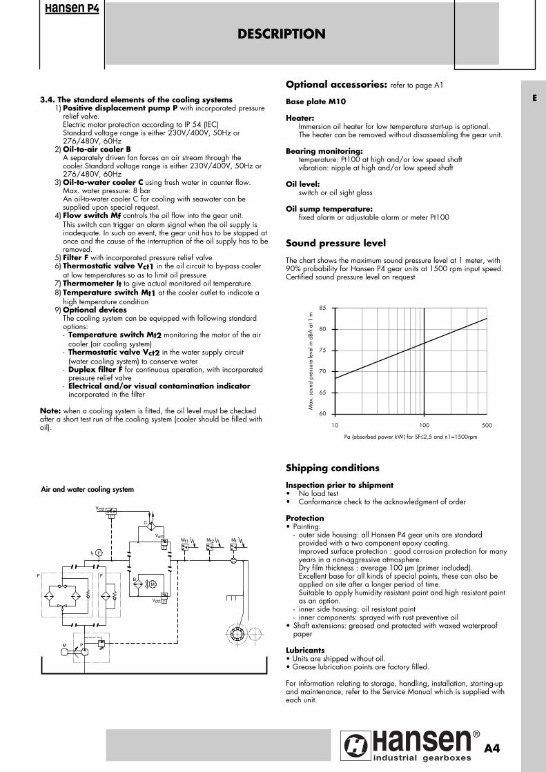
3.4. The standard elements of the cooling systems1) Positive displacement pump P with incorporated pressure
relief valve. Electric motor protection according to IP 54 (IEC) Standard voltage range is either 230V/400V, 50Hz or
276/480V, 60Hz 2) Oil-to-air cooler B
A separately driven fan forces an air stream through the cooler.Standard voltage range is either 230V/400V, 50Hz or 276/480V, 60Hz
3) Oil-to-water cooler C using fresh water in counter flow. Max. water pressure: 8 bar An oil-to-water cooler C for cooling with seawater can be
supplied upon special request.4) Flow switch Mf controls the oil flow into the gear unit.
This switch can trigger an alarm signal when the oil supply is inadequate. In such an event, the gear unit has to be stopped atonce and the cause of the interruption of the oil supply has to beremoved.
5) Filter F with incorporated pressure relief valve6) Thermostatic valve Vct1 in the oil circuit to by-pass cooler
at low temperatures so as to limit oil pressure7) Thermometer It to give actual monitored oil temperature 8) Temperature switch Mt1 at the cooler outlet to indicate a
high temperature condition9) Optional devices
The cooling system can be equipped with following standard options:- Temperature switch Mt2 monitoring the motor of the air
cooler (air cooling system)- Thermostatic valve Vct2 in the water supply circuit
(water cooling system) to conserve water- Duplex filter F for continuous operation, with incorporated
pressure relief valve- Electrical and/or visual contamination indicator
incorporated in the filter
Note: when a cooling system is fitted, the oil level must be checkedafter a short test run of the cooling system (cooler should be filled withoil).
Optional accessories: refer to page A1
Base plate M10
Heater:Immersion oil heater for low temperature start-up is optional.The heater can be removed without disassembling the gear unit.
Bearing monitoring:temperature: Pt100 at high and/or low speed shaftvibration: nipple at high and/or low speed shaft
Oil level: switch or oil sight glass
Oil sump temperature:fixed alarm or adjustable alarm or meter Pt100
Sound pressure level
The chart shows the maximum sound pressure level at 1 meter, with90% probability for Hansen P4 gear units at 1500 rpm input speed.Certified sound pressure level on request
Shipping conditions
Inspection prior to shipment• No load test• Conformance check to the acknowledgment of order
Protection• Painting: - outer side housing: all Hansen P4 gear units are standard
provided with a two component epoxy coating.Improved surface protection : good corrosion protection for manyyears in a non-aggressive atmosphere.Dry film thickness : average 100 µm (primer included).Excellent base for all kinds of special paints, these can also be applied on site after a longer period of time.Suitable to apply humidity resistant paint and high resistant paint as an option.
- inner side housing: oil resistant paint- inner components: sprayed with rust preventive oil
• Shaft extensions: greased and protected with waxed waterproof paper
Lubricants• Units are shipped without oil.• Grease lubrication points are factory filled.
For information relating to storage, handling, installation, starting-upand maintenance, refer to the Service Manual which is supplied witheach unit.
10 100
60
65
70
75
80
85
Pa (absorbed power kW) for SF≤2,5 and n1=1500rpm
Max
. sou
nd p
ress
ure
leve
l in
dBA
at 1
m
500
ansen
F
M P
F
It t°
B
t°
Vct1
C
Vct2
Mt1 Mf
M
Vct1 t°
Mt2
t°
Air and water cooling system
E
A4
Pagina: 1
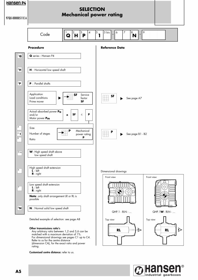
SELECTIONMechanical power rating
97QX-00000511E A
Servicefactor SF
H : Horizontal low speed shaft
Reference Data
ApplicationLoad conditionsPrime mover
SF
Size
Number of stages
Ratio
Mechanicalpower rating P
P
Actual absorbed power Paand/orMotor power Pm
SF P x ≤
High speed shaft extension L : left R : right
Low speed shaft extension L : left
R : right
See page A7
Dimensional drawings
Code Q H P4
15 bis - 6 7
N - 9
2H
3P
5 19
4
7
8N
6
SF
Procedure
Q series : Hansen P41Q
1
5 bis
A5
2 3 5 8
P : Parallel shafts
W : High speed shaft above low speed shaft
Note: only shaft arrangement LR or RL ispossible
N : Normal solid low speed shaft
Detailed example of selection: see page A8
Front view Front view
QHP.1 - RLN - ... QHP.1W - RLN - ...
RL RL
Top view Top view
ansen
Other transmissions ratio'sAny arbitrary ratio between 1,2 and 5,6 can be matched with a maximum deviation of 1%.For dimensional drawings see pages C1 up to C4.Refer to us for the centre distance (dimension CA), for the exact ratio and power rating.
Customised centre distance: refer to us.
See page B1 - B2P
Pagina: 1
Cooling group W1 W1 W2 W2 W3 W3
gear unit
type
iN
QHPE1
QHPF1W
QHPF1
QHPG1
QHPG1W
QHPF1
QHPG1W
QHPG1 QHPG1W QHPG1
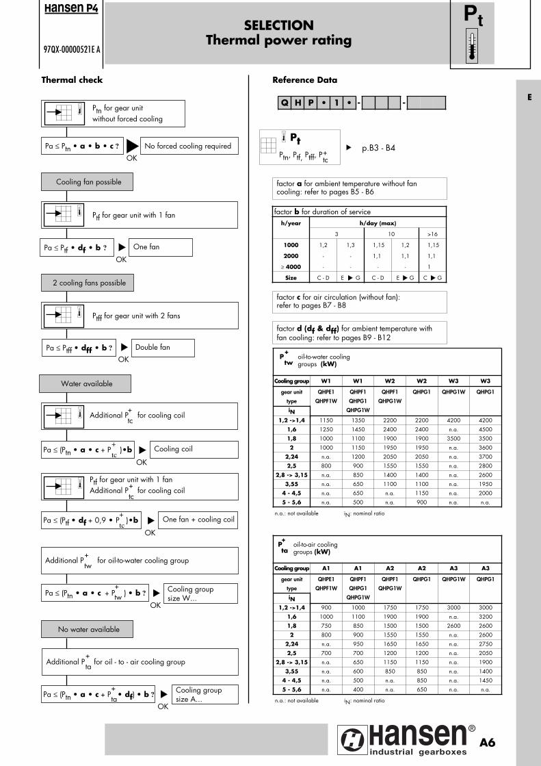
1,2 ->1,4 1150 1350 2200 2200 4200 4200
1,6 1250 1450 2400 2400 n.a. 4500
1,8 1000 1100 1900 1900 3500 3500
2 1000 1150 1950 1950 n.a. 3600
2,24 n.a. 1200 2050 2050 n.a. 3700
2,5 800 900 1550 1550 n.a. 2800
2,8 -> 3,15 n.a. 850 1400 1400 n.a. 2600
3,55 n.a. 650 1100 1100 n.a. 1950
4 - 4,5 n.a. 650 n.a. 1150 n.a. 2000
5 - 5,6 n.a. 500 n.a. 900 n.a. n.a.
n.a.: not available iN: nominal ratio
P oil-to-water cooling groups (kW)
+
tw
SELECTIONThermal power rating
97QX-00000521E A
Ptn for gear unit without forced cooling
OK
Thermal check
Pa ≤ Ptn • a • b • c ?
Cooling fan possible
No forced cooling required
Ptf for gear unit with 1 fan
Pa ≤ Ptf • df • b ?
2 cooling fans possible
One fan
Ptff for gear unit with 2 fans
Pa ≤ Ptff • dff • b ?
Water available
Double fan
Additional P for cooling coil
Pa ≤ (Ptn • a • c + P )•b Cooling coil
Pa ≤ (Ptn • a • c + P ) • b ? Cooling groupsize W...
Reference Data
Pa ≤ (Ptn • a • c + P • df) • b ?Cooling groupsize A...
No water available
Additional P for oil - to - air cooling group
Additional P for oil-to-water cooling group+tw
+tw
+ta
+ta
OK
OK
OK
OK
OK
+tc
+
tc
Q H P • 1 • - -
Pt
factor a for ambient temperature without fancooling: refer to pages B5 - B6
factor c for air circulation (without fan): refer to pages B7 - B8
factor d (df & dff) for ambient temperature withfan cooling: refer to pages B9 - B12
Ptf for gear unit with 1 fanAdditional P for cooling coil
+tc
Pa ≤ (Ptf • df + 0,9 • P )•b One fan + cooling coil
OK
+
tc
ansen
Pt
Ptn, Ptf, Ptff, P+tc
E
p.B3 - B4
factor b for duration of serviceh/year h/day (max)
3 10 >16
1000 1,2 1,3 1,15 1,2 1,15
2000 - - 1,1 1,1 1,1
≥ 4000 - - - - 1
Size C - D E G C - D E G C G
Cooling group A1 A1 A2 A2 A3 A3
gear unit
type
iN
QHPE1
QHPF1W
QHPF1
QHPG1
QHPG1W
QHPF1
QHPG1W
QHPG1 QHPG1W QHPG1
1,2 ->1,4 900 1000 1750 1750 3000 3000
1,6 1000 1100 1900 1900 n.a. 3200
1,8 750 850 1500 1500 2600 2600
2 800 900 1550 1550 n.a. 2600
2,24 n.a. 950 1650 1650 n.a. 2750
2,5 700 700 1200 1200 n.a. 2050
2,8 -> 3,15 n.a. 650 1150 1150 n.a. 1900
3,55 n.a. 600 850 850 n.a. 1400
4 - 4,5 n.a. 500 n.a. 850 n.a. 1450
5 - 5,6 n.a. 400 n.a. 650 n.a. n.a.
n.a.: not available iN: nominal ratio
P oil-to-air cooling groups (kW)
+
ta
A6
Pagina: 1
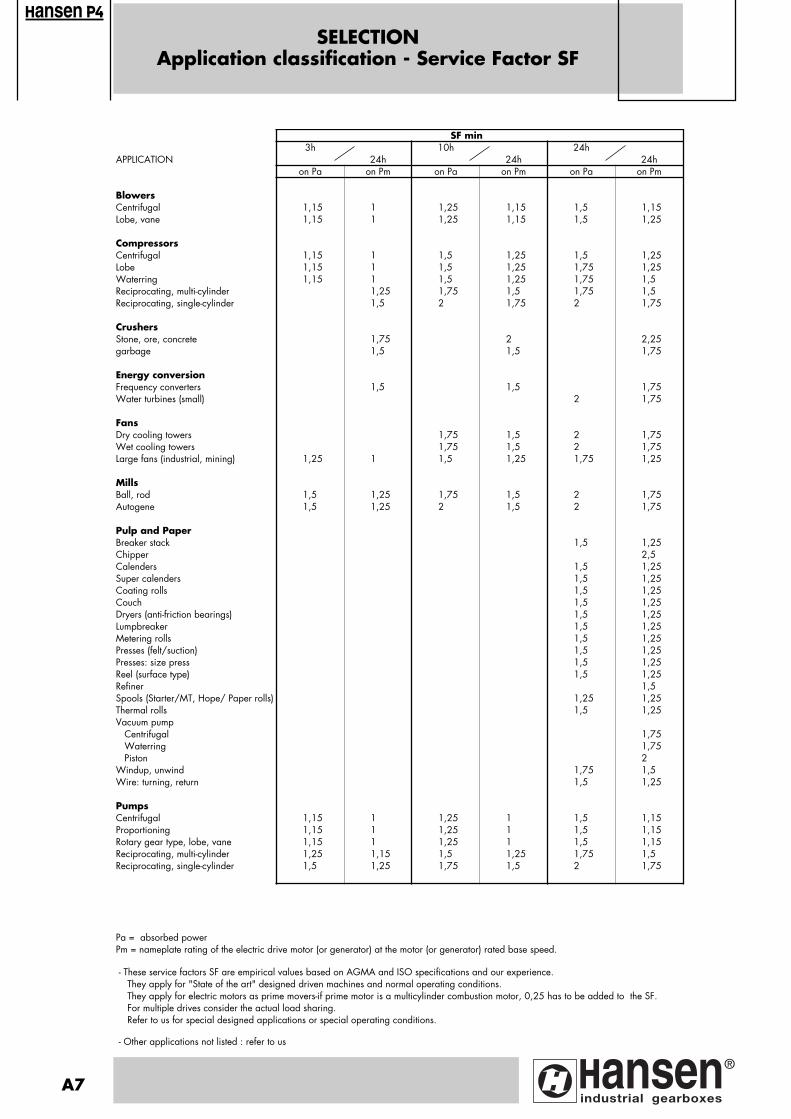
SELECTIONApplication classification - Service Factor SF
SF min3h 10h 24h
APPLICATION 24h 24h 24hon Pa on Pm on Pa on Pm on Pa on Pm
BlowersCentrifugal 1,15 1 1,25 1,15 1,5 1,15Lobe, vane 1,15 1 1,25 1,15 1,5 1,25
CompressorsCentrifugal 1,15 1 1,5 1,25 1,5 1,25Lobe 1,15 1 1,5 1,25 1,75 1,25Waterring 1,15 1 1,5 1,25 1,75 1,5Reciprocating, multi-cylinder 1,25 1,75 1,5 1,75 1,5Reciprocating, single-cylinder 1,5 2 1,75 2 1,75
CrushersStone, ore, concrete 1,75 2 2,25garbage 1,5 1,5 1,75
Energy conversionFrequency converters 1,5 1,5 1,75Water turbines (small) 2 1,75
FansDry cooling towers 1,75 1,5 2 1,75Wet cooling towers 1,75 1,5 2 1,75Large fans (industrial, mining) 1,25 1 1,5 1,25 1,75 1,25
MillsBall, rod 1,5 1,25 1,75 1,5 2 1,75Autogene 1,5 1,25 2 1,5 2 1,75
Pulp and PaperBreaker stack 1,5 1,25Chipper 2,5Calenders 1,5 1,25Super calenders 1,5 1,25Coating rolls 1,5 1,25Couch 1,5 1,25Dryers (anti-friction bearings) 1,5 1,25Lumpbreaker 1,5 1,25Metering rolls 1,5 1,25Presses (felt/suction) 1,5 1,25Presses: size press 1,5 1,25Reel (surface type) 1,5 1,25Refiner 1,5Spools (Starter/MT, Hope/ Paper rolls) 1,25 1,25Thermal rolls 1,5 1,25Vacuum pump Centrifugal 1,75 Waterring 1,75 Piston 2Windup, unwind 1,75 1,5Wire: turning, return 1,5 1,25
PumpsCentrifugal 1,15 1 1,25 1 1,5 1,15Proportioning 1,15 1 1,25 1 1,5 1,15Rotary gear type, lobe, vane 1,15 1 1,25 1 1,5 1,15Reciprocating, multi-cylinder 1,25 1,15 1,5 1,25 1,75 1,5Reciprocating, single-cylinder 1,5 1,25 1,75 1,5 2 1,75
Pa = absorbed powerPm = nameplate rating of the electric drive motor (or generator) at the motor (or generator) rated base speed.
- These service factors SF are empirical values based on AGMA and ISO specifications and our experience. They apply for "State of the art" designed driven machines and normal operating conditions. They apply for electric motors as prime movers-if prime motor is a multicylinder combustion motor, 0,25 has to be added to the SF. For multiple drives consider the actual load sharing. Refer to us for special designed applications or special operating conditions.
- Other applications not listed : refer to us
A7
ansen
Pagina: 1
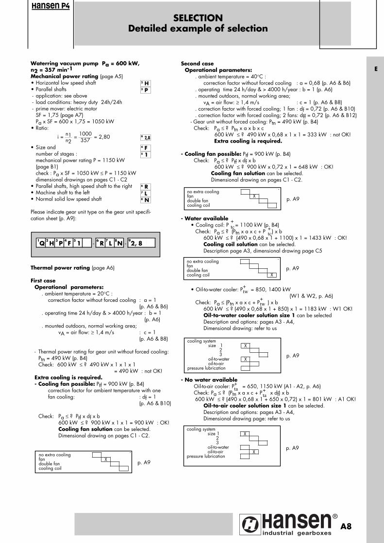
SELECTIONDetailed example of selection
ansen
Waterring vacuum pump Pa = 600 kW, n2 = 357 min-1Mechanical power rating (page A5)• Horizontal low speed shaft• Parallel shafts - application: see above - load conditions: heavy duty 24h/24h - prime mover: electric motor
SF = 1,75 (page A7)Pa x SF = 600 x 1,75 = 1050 kW
• Ratio:
• Size and number of stages : mechanical power rating P = 1150 kW
(page B1) check : Pa x SF = 1050 kW ≤ P = 1150 kW dimensional drawings on pages C1 - C2• Parallel shafts, high speed shaft to the right• Machine shaft to the left• Normal solid low speed shaft
Please indicate gear unit type on the gear unit specifi-cation sheet (p. A9):
n1 1000n2 357
i = = = 2,80
Second caseOperational parameters:
. ambient temperature = 40°C :correction factor without forced cooling : a = 0,68 (p. A6 & B6)
. operating time 24 h/day & > 4000 h/year : b = 1 (p. A6)
. mounted outdoors, normal working area;vA = air flow: ≥ 1,4 m/s : c = 1 (p. A6 & B8)
. correction factor with forced cooling; 1 fan : df = 0,72 (p. A6 & B10)
. correction factor with forced cooling; 2 fans: dff = 0,72 (p. A6 & B12)- Gear unit without forced cooling: Ptn = 490 kW (p. B4) Check: Pa ≤ ? Ptn x a x b x c 600 kW ≤ ? 490 kW x 0,68 x 1 x 1 = 333 kW : not OK!
Extra cooling is required.
- Cooling fan possible: Ptf = 900 kW (p. B4) Check: Pa ≤ ? Ptf x df x b 600 kW ≤ ? 900 kW x 0,72 x 1 = 648 kW : OK!
Cooling fan solution can be selected. Dimensional drawing on pages C1 - C2.
- Water available• Cooling coil: P = 1100 kW (p. B4) Check: Pa ≤ ? (Ptn x a x c + P ) x b
600 kW ≤ ? (490 x 0,68 x 1 + 1100) x 1 = 1433 kW : OK! Cooling coil solution can be selected.
Description page A3, dimensional drawing page C5
• Oil-to-water cooler: P = 850, 1400 kW
(W1 & W2, p. A6) Check: Pa ≤ (Ptn x a x c + P ) x b
600 kW ≤ ? (490 x 0,68 x 1 + 850) x 1 = 1183 kW : W1 OK! Oil-to-water cooler solution size 1 can be selected Description and options: pages A3 - A4,
Dimensional drawing: refer to us
- No water available Oil-to-air cooler: P = 650, 1150 kW (A1 - A2, p. A6) Check: Pa ≤ ? (Ptn x a x c + P x df) x b
600 kW ≤ ? (490 x 0,68 x 1 + 650 x 0,72) x 1 = 801 kW : A1 OK! Oil-to-air cooler solution size 1 can be selected.
Description and options: pages A3 - A4, Dimensional drawing page: refer to us
7 L8 N
6 R
5 1
4 F
9 2,8
3 P
2 H
1Q
2 H
3 P
4 F
5 1 - 6
R7 L
8N - 9
2, 8
p. A9
p. A9no extra coolingfan Xdouble fancooling coil
no extra coolingfandouble fancooling coil X
cooling system size 1 X 2 3 oil-to-water X oil-to-airpressure lubrication
+tc +
tc
+tw
+tw
p. A9
Thermal power rating (page A6)
First caseOperational parameters:
. ambient temperature = 20°C : correction factor without forced cooling : a = 1
(p. A6 & B6). operating time 24 h/day & > 4000 h/year : b = 1
(p. A6). mounted outdoors, normal working area;
vA = air flow: ≥ 1,4 m/s : c = 1(p. A6 & B8)
- Thermal power rating for gear unit without forced cooling: Ptn = 490 kW (p. B4)Check: 600 kW ≤ ? 490 kW x 1 x 1 x 1
= 490 kW : not OK!Extra cooling is required.- Cooling fan possible: Ptf = 900 kW (p. B4)
correction factor for ambient temperature with one fan cooling: : df = 1
(p. A6 & B10)
Check: Pa ≤ ? Ptf x df x b 600 kW ≤ ? 900 kW x 1 x 1 = 900 kW : OK!
Cooling fan solution can be selected. Dimensional drawing on pages C1 - C2.
p. A9no extra coolingfan Xdouble fancooling coil
p. A9
cooling system size 1 X 2 3 oil-to-water oil-to-air Xpressure lubrication
+ta +
ta
E
A8
Pagina: 1
GEAR UNIT SPECIFICATIONS97QX-00000532E A
Ref : Date : Name : Signature :
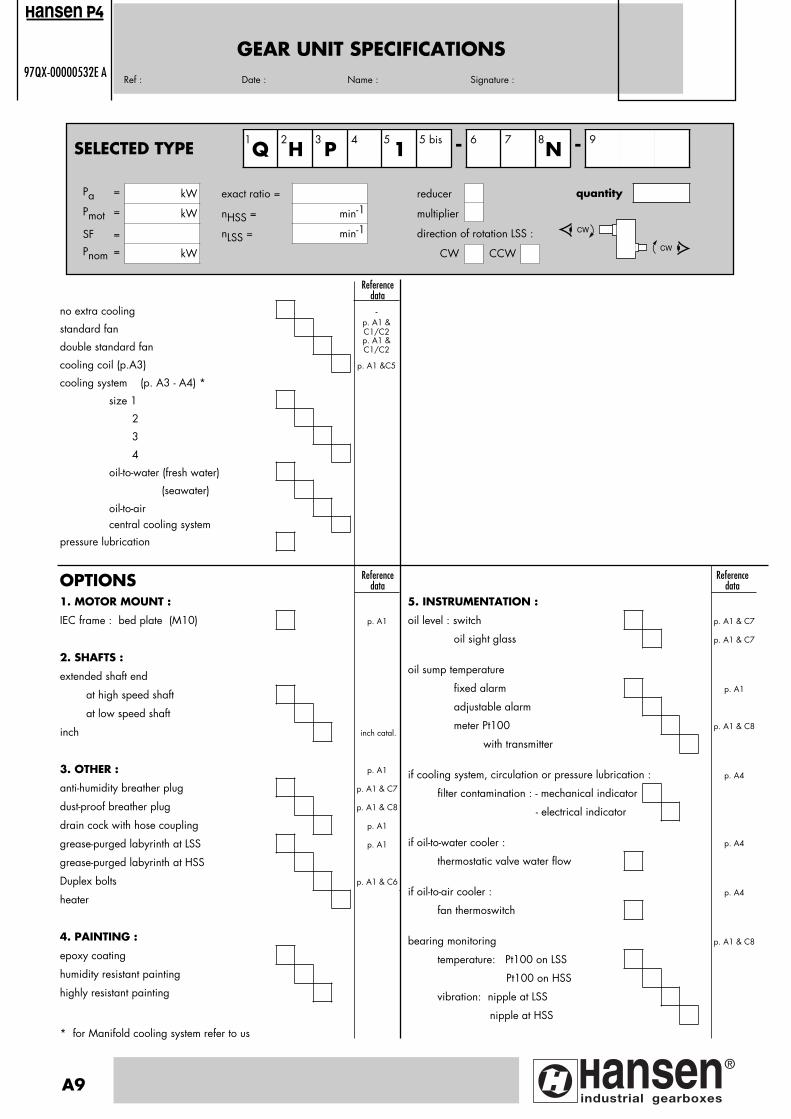
1. MOTOR MOUNT :
IEC frame : bed plate (M10) p. A1
2. SHAFTS :
extended shaft end
at high speed shaft
at low speed shaft
inch inch catal.
3. OTHER : p. A1
anti-humidity breather plug p. A1 & C7
dust-proof breather plug p. A1 & C8
drain cock with hose coupling p. A1
grease-purged labyrinth at LSS p. A1
grease-purged labyrinth at HSS
Duplex bolts p. A1 & C6
heater
4. PAINTING :
epoxy coating
humidity resistant painting
highly resistant painting
* for Manifold cooling system refer to us
OPTIONS Referencedata
Referencedata
no extra cooling -
standard fanp. A1 &C1/C2
double standard fanp. A1 &C1/C2
cooling coil (p.A3) p. A1 &C5
cooling system (p. A3 - A4) *
size 1
2
3
4
oil-to-water (fresh water)
(seawater)
oil-to-air central cooling system
pressure lubrication
Referencedata
5. INSTRUMENTATION :
oil level : switch p. A1 & C7
oil sight glass p. A1 & C7
oil sump temperature
fixed alarm p. A1
adjustable alarm
meter Pt100 p. A1 & C8
with transmitter
if cooling system, circulation or pressure lubrication : p. A4
filter contamination : - mechanical indicator
- electrical indicator
if oil-to-water cooler : p. A4
thermostatic valve water flow
if oil-to-air cooler : p. A4
fan thermoswitch
bearing monitoring p. A1 & C8
temperature: Pt100 on LSS
Pt100 on HSS
vibration: nipple at LSS
nipple at HSS
A9
ansen
SELECTED TYPE Q H P4
15 bis - 6 7
N - 9
CW
CW
1 2 3 5 8
Pa = kW exact ratio = reducer
Pmot = kW nHSS = min-1 multiplier
SF = nLSS = min-1 direction of rotation LSS :
Pnom = kW CW CCW
quantity
Pagina: 1
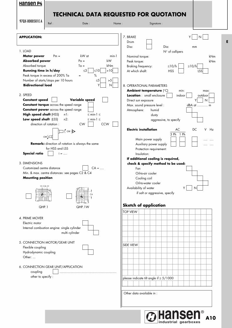
TECHNICAL DATA REQUESTED FOR QUOTATION97QX-0000501E A
Ref : Date : Name : Signature :
APPLICATION:
1. LOAD Motor power Pm = kW at min-1 Absorbed power Pa = kW Absorbed torque Ta = kNm Running time in h/day ≤3 ≤10 >10 Peak torque in excess of 200% Ta = % Number of starts/stops per 10 hours ≤5 >5 Bidirectional load Y N
2. SPEED Constant speed Variable speed Constant torque across the speed range Constant power across the speed range High speed shaft (HSS) n1: ≤ min-1 ≤ Low speed shaft (LSS) n2: ≤ min-1 ≤ direction of rotation : CW CCW
Remark: direction of rotation is always the same for HSS and LSS Special ratio i = ....
3. DIMENSIONS Customized centre distance CA = .... Min. & max. centre distances: see pages C2 & C4 Mounting position
4. PRIME MOVER Electric motor Internal combustion engine: single cylinder multi cylinder
5. CONNECTION MOTOR/GEAR UNIT Flexible coupling Hydrodynamic coupling Other: ...
6. CONNECTION GEAR UNIT/APPLICATION coupling ........................................................... other to specify :
Sketch of applicationTOP VIEW
SIDE VIEW
please indicate tilt angle if ≥ 5/1000
7. BRAKE Y N Drum Disc Dia: mm N° of callipers Nominal torque: kNm Peak torque: kNm Braking frequency: ≤10/h ≥10/h At which shaft: HSS LSS
8. OPERATIONAL PARAMETERS Ambient temperature (°C) min: max: Location : small enclosure indoor outdoor Direct sun exposure Y N Max. sound pressure level : dBA at ........... m Atmosphere: humid dusty aggressive, to specify
Electric installation AC DC V Hz 3 Ph 1 Ph Main power supply .... .... Auxiliary power supply .... .... Protection requirement: Insulation: If additional cooling is required, check & specify method to be used: Fan Oil-to-air cooler Cooling coil Oil-to-water cooler Availability of water Y N if salt or aggressive, specify
Other data available in :
CW
CW
ansen
CA
CA
QHP.1 QHP.1W
E
A10
Pagina: 1
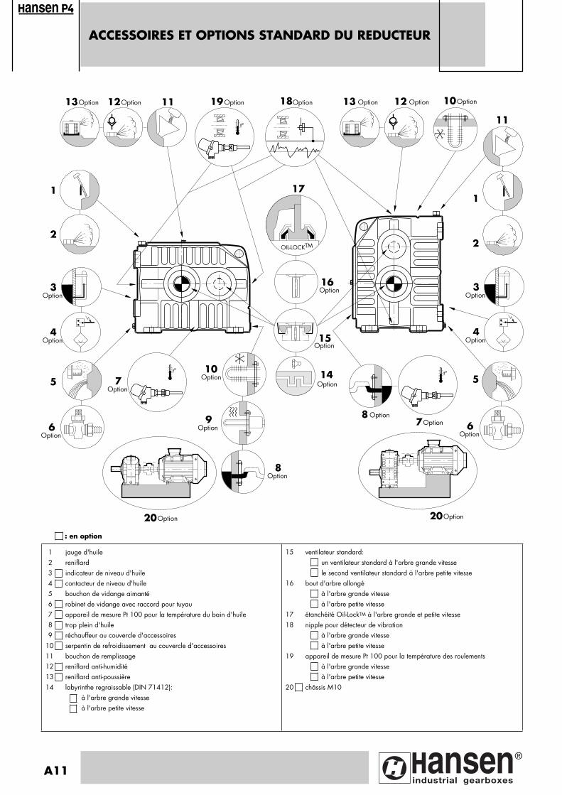
ACCESSOIRES ET OPTIONS STANDARD DU REDUCTEUR
ansen
1 jauge d'huile2 reniflard3 indicateur de niveau d'huile4 contacteur de niveau d'huile5 bouchon de vidange aimanté6 robinet de vidange avec raccord pour tuyau7 appareil de mesure Pt 100 pour la température du bain d'huile8 trop plein d'huile9 réchauffeur au couvercle d'accessoires
10 serpentin de refroidissement au couvercle d'accessoires11 bouchon de remplissage12 reniflard anti-humidité13 reniflard anti-poussière14 labyrinthe regraissable (DIN 71412):
à l'arbre grande vitesseà l'arbre petite vitesse
15 ventilateur standard:un ventilateur standard à l'arbre grande vitessele second ventilateur standard à l'arbre petite vitesse
16 bout d'arbre allongéà l'arbre grande vitesseà l'arbre petite vitesse
17 étanchéité Oil-LockTM à l'arbre grande et petite vitesse18 nipple pour détecteur de vibration
à l'arbre grande vitesseà l'arbre petite vitesse
19 appareil de mesure Pt 100 pour la température des roulementsà l'arbre grande vitesseà l'arbre petite vitesse
20 châssis M10
: en option
A11
OIL-LOCKTM
t°
1
2
4Option
3Option
5
6Option
t°
7Option
8Option
10Option
8 Option7Option 6
Option
5
2
1
11
13 Option
15
16
18191112Option13Option
20Option 20Option
10Option
t°���
����
���
��
��
��
���
�
��
�
��
�����
�
�
�
�
�
����
��
�
�
14
12 Option
4Option
3Option
Option
Option Option
Option
9Option
Option
17
Pagina: 1

Page
Section A
Généralités
Accessoires et options standard du réducteur
Description
SélectionPuissance mécanique nominale
Puissance thermique
Classification des applications - Facteurs de Service SF
Exemple de sélection détaillé
Spécifications du réducteur
Données techniques pour la demande d'offre
A11
A13 - A14
A15 A16A17A18
A19
A20
Puissances mécaniques nominalesMoments d'inertie J
B1 - B2B2
Puissances thermiques nominales B3 - B4
Section B Facteur a pour température ambiante sans refroidissement par ventilateur
B5 - B6
Tables Facteur c pour circulation d'air sans ventilateur B7 - B8
Facteur d pour température ambiante avec refroidissement par ventilateur
df pour 1 ventilateurB9 - B10
dff pour 2 ventilateurs B11 - B12
Section C
Plans d'encombrement pour réducteurs standardRéducteur à engrenages avec arbre G.V. et P.V. dans le même plan
horizontal (QHP.1)C1 - C2
Plans d'en-Réducteur à engrenages avec arbre G.V. au-dessus de l'arbre P.V. (QHP.1W) C3 - C4
combrement
Plans d'encombrement supplémentaires pour options
Serpentin de refroidissement
Réchauffeur
Voyant d'huile
Contacteur de niveau d'huile
Bouchon d'aération anti-poussière
Robinet de vidange
Appareil de mesure Pt100
C5C6C7C7C7C8C8
INDEX GENERAL
ansen
F
A12
Pagina: 1
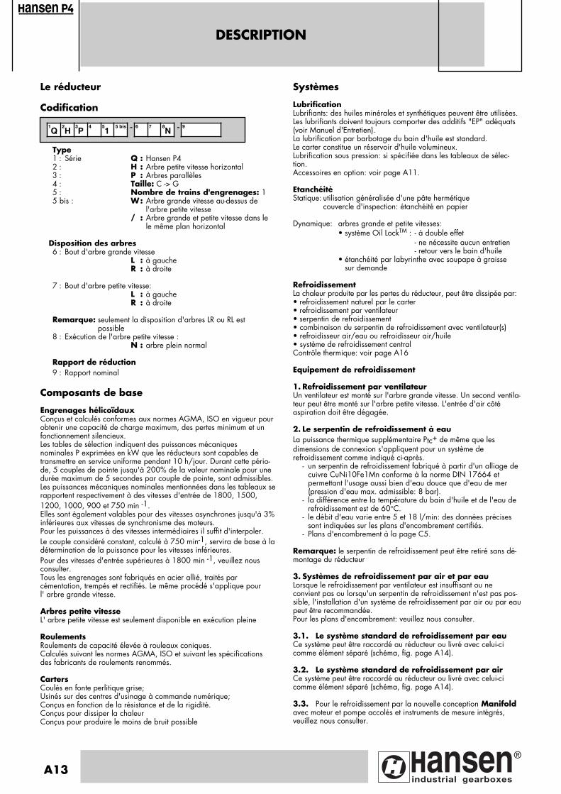
DESCRIPTION
Le réducteur
Codification
Type1 : Série Q : Hansen P42 : H : Arbre petite vitesse horizontal3 : P : Arbres parallèles4 : Taille: C -> G5 : Nombre de trains d'engrenages: 15 bis : W: Arbre grande vitesse au-dessus de
l'arbre petite vitesse/ : Arbre grande et petite vitesse dans le
le même plan horizontal
Disposition des arbres6 : Bout d'arbre grande vitesse
L : à gaucheR : à droite
7 : Bout d'arbre petite vitesse:L : à gaucheR : à droite
Remarque: seulement la disposition d'arbres LR ou RL est possible
8 : Exécution de l'arbre petite vitesse :N : arbre plein normal
Rapport de réduction9 : Rapport nominal
Composants de base
Engrenages hélicoïdauxConçus et calculés conformes aux normes AGMA, ISO en vigueur pourobtenir une capacité de charge maximum, des pertes minimum et unfonctionnement silencieux.Les tables de sélection indiquent des puissances mécaniques nominales P exprimées en kW que les réducteurs sont capables detransmettre en service uniforme pendant 10 h/jour. Durant cette pério-de, 5 couples de pointe jusqu'à 200% de la valeur nominale pour unedurée maximum de 5 secondes par couple de pointe, sont admissibles.Les puissances mécaniques nominales mentionnées dans les tableaux serapportent respectivement à des vitesses d'entrée de 1800, 1500,1200, 1000, 900 et 750 min -1.Elles sont également valables pour des vitesses asynchrones jusqu'à 3%inférieures aux vitesses de synchronisme des moteurs. Pour les puissances à des vitesses intermédiaires il suffit d'interpoler. Le couple considéré constant, calculé à 750 min-1, servira de base à ladétermination de la puissance pour les vitesses inférieures. Pour des vitesses d'entrée supérieures à 1800 min -1, veuillez nousconsulter.Tous les engrenages sont fabriqués en acier allié, traités parcémentation, trempés et rectifiés. Le même procédé s'applique pour l' arbre grande vitesse.
Arbres petite vitesseL' arbre petite vitesse est seulement disponible en exécution pleine
RoulementsRoulements de capacité élevée à rouleaux coniques. Calculés suivant les normes AGMA, ISO et suivant les spécificationsdes fabricants de roulements renommés.
CartersCoulés en fonte perlitique grise;Usinés sur des centres d'usinage à commande numérique;Conçus en fonction de la résistance et de la rigidité.Conçus pour dissiper la chaleurConçus pour produire le moins de bruit possible
Systèmes
LubrificationLubrifiants: des huiles minérales et synthétiques peuvent être utilisées.Les lubrifiants doivent toujours comporter des additifs "EP" adéquats(voir Manuel d'Entretien).La lubrification par barbotage du bain d'huile est standard. Le carter constitue un réservoir d'huile volumineux.Lubrification sous pression: si spécifiée dans les tableaux de sélec-tion.Accessoires en option: voir page A11.
EtanchéitéStatique: utilisation généralisée d'une pâte hermétique
couvercle d'inspection: étanchéité en papier
Dynamique: arbres grande et petite vitesses:• système Oil LockTM : - à double effet
- ne nécessite aucun entretien- retour vers le bain d'huile
• étanchéité par labyrinthe avec soupape à graisse sur demande
RefroidissementLa chaleur produite par les pertes du réducteur, peut être dissipée par:• refroidissement naturel par le carter• refroidissement par ventilateur• serpentin de refroidissement• combinaison du serpentin de refroidissement avec ventilateur(s)• refroidisseur air/eau ou refroidisseur air/huile• système de refroidissement centralContrôle thermique: voir page A16
Equipement de refroidissement
1. Refroidissement par ventilateurUn ventilateur est monté sur l'arbre grande vitesse. Un second ventila-teur peut être monté sur l'arbre petite vitesse. L'entrée d'air côtéaspiration doit être dégagée.
2. Le serpentin de refroidissement à eauLa puissance thermique supplémentaire Ptc+ de même que lesdimensions de connexion s'appliquent pour un système derefroidissement comme indiqué ci-après.
- un serpentin de refroidissement fabriqué à partir d'un alliage de cuivre CuNi10Fe1Mn conforme à la norme DIN 17664 et permettant l'usage aussi bien d'eau douce que d'eau de mer (pression d'eau max. admissible: 8 bar).
- la différence entre la température du bain d'huile et de l'eau de refroidissement est de 60°C.
- le débit d'eau varie entre 5 et 18 l/min: des données précises sont indiquées sur les plans d'encombrement certifiés.
- Plans d'encombrement à la page C5.
Remarque: le serpentin de refroidissement peut être retiré sans dé-montage du réducteur
3. Systèmes de refroidissement par air et par eauLorsque le refroidissement par ventilateur est insuffisant ou neconvient pas ou lorsqu'un serpentin de refroidissement n'est pas pos-sible, l'installation d'un système de refroidissement par air ou par eaupeut être recommandée.Pour les plans d'encombrement: veuillez nous consulter.
3.1. Le système standard de refroidissement par eauCe système peut être raccordé au réducteur ou livré avec celui-cicomme élément séparé (schéma, fig. page A14).
3.2. Le système standard de refroidissement par airCe système peut être raccordé au réducteur ou livré avec celui-cicomme élément séparé (schéma, fig. page A14).
3.3. Pour le refroidissement par la nouvelle conception Manifoldavec moteur et pompe accolés et instruments de mesure intégrés, veuillez nous consulter.
1Q
2H
3P
4 51
5 bis - 6 7 8N - 9
ansen
A13
Pagina: 1
DESCRIPTION
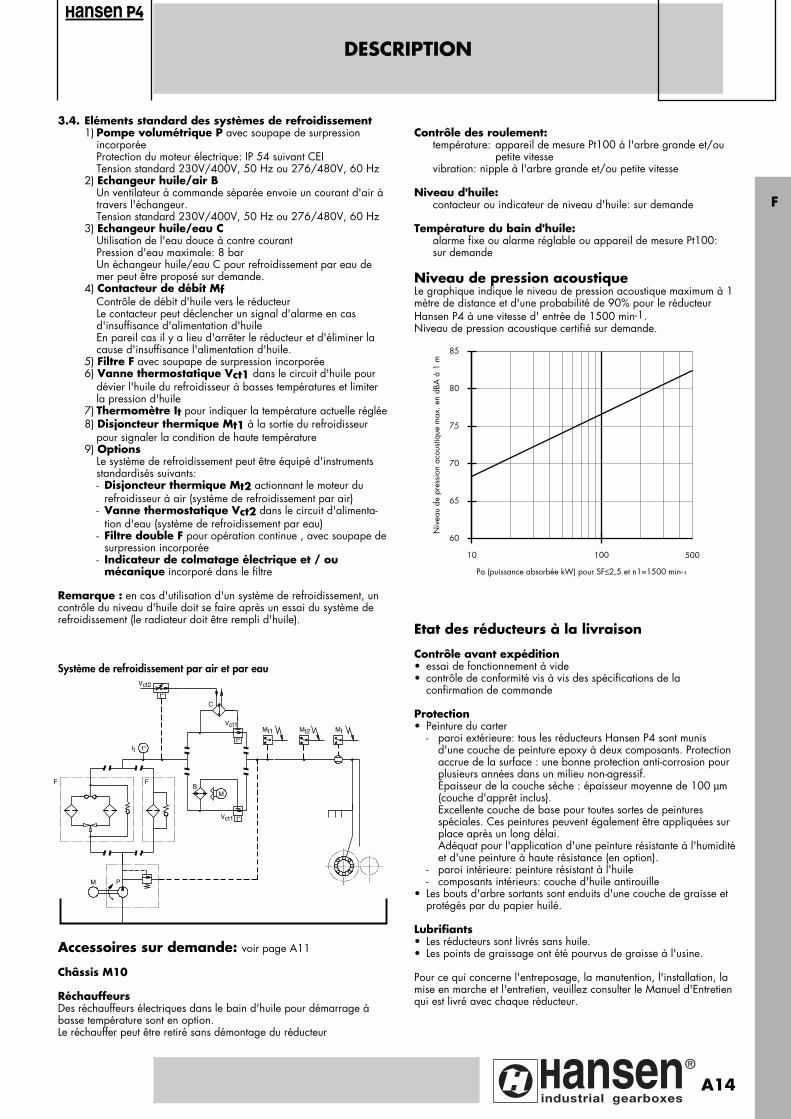
3.4. Eléments standard des systèmes de refroidissement1) Pompe volumétrique P avec soupape de surpression
incorporée Protection du moteur électrique: IP 54 suivant CEI Tension standard 230V/400V, 50 Hz ou 276/480V, 60 Hz
2) Echangeur huile/air B Un ventilateur à commande séparée envoie un courant d'air à
travers l'échangeur. Tension standard 230V/400V, 50 Hz ou 276/480V, 60 Hz
3) Echangeur huile/eau C Utilisation de l'eau douce à contre courant Pression d'eau maximale: 8 bar Un échangeur huile/eau C pour refroidissement par eau de
mer peut être proposé sur demande. 4) Contacteur de débit Mf
Contrôle de débit d'huile vers le réducteur Le contacteur peut déclencher un signal d'alarme en cas
d'insuffisance d'alimentation d'huile En pareil cas il y a lieu d'arrêter le réducteur et d'éliminer la
cause d'insuffisance l'alimentation d'huile.5) Filtre F avec soupape de surpression incorporée6) Vanne thermostatique Vct1 dans le circuit d'huile pour
dévier l'huile du refroidisseur à basses températures et limiterla pression d'huile
7) Thermomètre It pour indiquer la température actuelle réglée8) Disjoncteur thermique Mt1 à la sortie du refroidisseur
pour signaler la condition de haute température9) Options
Le système de refroidissement peut être équipé d'instruments standardisés suivants:
- Disjoncteur thermique Mt2 actionnant le moteur du refroidisseur à air (système de refroidissement par air)
- Vanne thermostatique Vct2 dans le circuit d'alimenta-tion d'eau (système de refroidissement par eau)
- Filtre double F pour opération continue , avec soupape desurpression incorporée
- Indicateur de colmatage électrique et / ou mécanique incorporé dans le filtre
Remarque : en cas d'utilisation d'un système de refroidissement, uncontrôle du niveau d'huile doit se faire après un essai du système de refroidissement (le radiateur doit être rempli d'huile).
Contrôle des roulement:température: appareil de mesure Pt100 à l'arbre grande et/ou
petite vitessevibration: nipple à l'arbre grande et/ou petite vitesse
Niveau d'huile: contacteur ou indicateur de niveau d'huile: sur demande
Température du bain d'huile:alarme fixe ou alarme réglable ou appareil de mesure Pt100: sur demande
Niveau de pression acoustiqueLe graphique indique le niveau de pression acoustique maximum à 1mètre de distance et d'une probabilité de 90% pour le réducteur Hansen P4 à une vitesse d' entrée de 1500 min-1.Niveau de pression acoustique certifié sur demande.
Etat des réducteurs à la livraison
Contrôle avant expédition• essai de fonctionnement à vide• contrôle de conformité vis à vis des spécifications de la
confirmation de commande
Protection• Peinture du carter
- paroi extérieure: tous les réducteurs Hansen P4 sont munis d'une couche de peinture epoxy à deux composants. Protection accrue de la surface : une bonne protection anti-corrosion pour plusieurs années dans un milieu non-agressif.Épaisseur de la couche sèche : épaisseur moyenne de 100 µm(couche d'apprêt inclus).Excellente couche de base pour toutes sortes de peintures spéciales. Ces peintures peuvent également être appliquées sur place après un long délai.Adéquat pour l'application d'une peinture résistante à l'humiditéet d'une peinture à haute résistance (en option).
- paroi intérieure: peinture résistant à l'huile - composants intérieurs: couche d'huile antirouille• Les bouts d'arbre sortants sont enduits d'une couche de graisse et
protégés par du papier huilé.
Lubrifiants• Les réducteurs sont livrés sans huile.• Les points de graissage ont été pourvus de graisse à l'usine.
Pour ce qui concerne l'entreposage, la manutention, l'installation, lamise en marche et l'entretien, veuillez consulter le Manuel d'Entretienqui est livré avec chaque réducteur.
ansen
F
M P
F
It t°
B
t°
Vct1
C
Vct2
Mt1 Mf
M
Vct1 t°
Mt2
t°
Système de refroidissement par air et par eau
10 100
60
65
70
75
80
85
Pa (puissance absorbée kW) pour SF≤2,5 et n1=1500 min-1
Niv
eau
de p
ress
ion
acou
stiqu
e m
ax. e
n dB
A à
1 m
500
Accessoires sur demande: voir page A11
Châssis M10
RéchauffeursDes réchauffeurs électriques dans le bain d'huile pour démarrage àbasse température sont en option. Le réchauffer peut être retiré sans démontage du réducteur
F
A14
Pagina: 1
Facteur deserviceSF
SELECTIONPuissance mécanique nominale
97QX-00000511F A
H : Arbre petite vitesse horizontal
Données de référence
ApplicationServiceMoteur
SF
Taille
Nombre d'étages
Rapport
Puissancemécaniquenominale P
P
Puissance absorbée Paet/ouPuissance motrice Pm
SF P x ≤
Bout d'arbre grande vitesse L : à gauche R : à droite
Bout d'arbre petite vitesse L : à gauche R : à droite
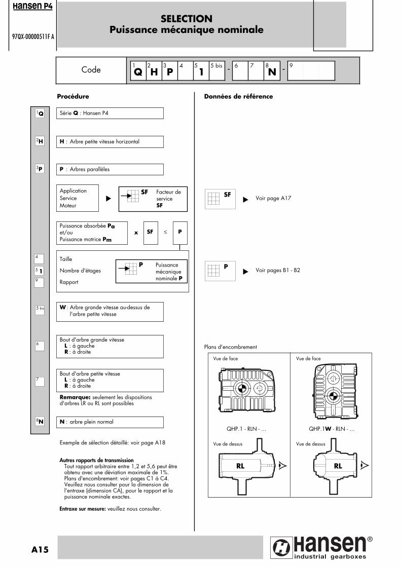
Voir page A17
Plans d'encombrement
Code Q H P4
15 bis - 6 7
N - 9
2H
3P
5 19
4
7
8N
6
SF
Procédure
Série Q : Hansen P41Q
1
5 bis
A15
2 3 5 8
P : Arbres parallèles
W : Arbre grande vitesse au-dessus de l'arbre petite vitesse
Remarque: seulement les dispositionsd'arbres LR ou RL sont possibles
N : arbre plein normal
Exemple de sélection détaillé: voir page A18
Vue de face Vue de face
QHP.1 - RLN - ... QHP.1W - RLN - ...
RL RL
Vue de dessus Vue de dessus
ansen
Autres rapports de transmissionTout rapport arbitraire entre 1,2 et 5,6 peut être obtenu avec une déviation maximale de 1%.Plans d'encombrement: voir pages C1 à C4.Veuillez nous consulter pour la dimension de l'entraxe (dimension CA), pour le rapport et la puissance nominale exactes.
Entraxe sur mesure: veuillez nous consulter.
Voir pages B1 - B2P
Pagina: 1
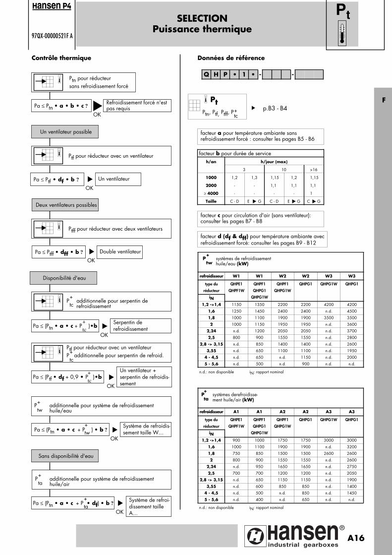
refroidisseur W1 W1 W2 W2 W3 W3
type du
réducteur
iN
QHPE1
QHPF1W
QHPF1
QHPG1
QHPG1W
QHPF1
QHPG1W
QHPG1 QHPG1W QHPG1
1,2 ->1,4 1150 1350 2200 2200 4200 4200
1,6 1250 1450 2400 2400 n.d. 4500
1,8 1000 1100 1900 1900 3500 3500
2 1000 1150 1950 1950 n.d. 3600
2,24 n.d. 1200 2050 2050 n.d. 3700
2,5 800 900 1550 1550 n.d. 2800
2,8 -> 3,15 n.d. 850 1400 1400 n.d. 2600
3,55 n.d. 650 1100 1100 n.d. 1950
4 - 4,5 n.d. 650 n.d. 1150 n.d. 2000
5 - 5,6 n.d. 500 n.d. 900 n.d. n.d.
n.d.: non disponible iN: rapport nominal
P systèmes de refroidissement huile/eau (kW)
+
tw
facteur b pour durée de serviceh/an h/jour (max)
3 10 >16
1000 1,2 1,3 1,15 1,2 1,15
2000 - - 1,1 1,1 1,1
≥ 4000 - - - - 1
Taille C - D E G C - D E G C G
SELECTIONPuissance thermique
97QX-00000521F A
Ptn pour réducteursans refroidissement forcé
OK
Contrôle thermique
Pa ≤ Ptn • a • b • c ?
Un ventilateur possible
Refroidissement forcé n'estpas requis
Ptf pour réducteur avec un ventilateur
Pa ≤ Ptf • df • b ?
Deux ventilateurs possibles
Un ventilateur
Ptff pour réducteur avec deux ventilateurs
Pa ≤ Ptff • dff • b ?
Disponibilité d'eau
Double ventilateur
P additionnelle pour serpentin de refroidissement
Pa ≤ (Ptn • a • c + P )•bSerpentin de refroidissement
Pa ≤ (Ptn • a • c + P ) • b ?Système de refroidis-sement taille W...
Données de référence
Pa ≤ (Ptn • a • c + P • df) • b ?Système de refroi-dissement tailleA...
Sans disponibilité d'eau
P additionnelle pour système de refroidissement huile/air
P additionnelle pour système de refroidissement huile/eau
+tw
+tw
+ta
+ta
OK
OK
OK
OK
OK
+tc
+
tc
Q H P • 1 • - -
Pt
facteur a pour température ambiante sansrefroidissement forcé : consulter les pages B5 - B6
facteur c pour circulation d'air (sans ventilateur):consulter les pages B7 - B8
facteur d (df & dff) pour température ambiante avecrefroidissement forcé: consulter les pages B9 - B12
Ptf pour réducteur avec un ventilateurP additionnelle pour serpentin de refroid.+tc
Pa ≤ (Ptf • df + 0,9 • P )•bUn ventilateur + serpentin de refroidis-sementOK
+
tc
ansen
Pt
Ptn, Ptf, Ptff, P+tc
Fp.B3 - B4
refroidisseur A1 A1 A2 A2 A3 A3
type du
réducteur
iN
QHPE1
QHPF1W
QHPF1
QHPG1
QHPG1W
QHPF1
QHPG1W
QHPG1 QHPG1W QHPG1
1,2 ->1,4 900 1000 1750 1750 3000 3000
1,6 1000 1100 1900 1900 n.d. 3200
1,8 750 850 1500 1500 2600 2600
2 800 900 1550 1550 n.d. 2600
2,24 n.d. 950 1650 1650 n.d. 2750
2,5 700 700 1200 1200 n.d. 2050
2,8 -> 3,15 n.d. 650 1150 1150 n.d. 1900
3,55 n.d. 600 850 850 n.d. 1400
4 - 4,5 n.d. 500 n.d. 850 n.d. 1450
5 - 5,6 n.d. 400 n.d. 650 n.d. n.d.
n.d.: non disponible iN: rapport nominal
P systèmes derefroidisse-ment huile/air (kW)
+
ta
A16
Pagina: 1
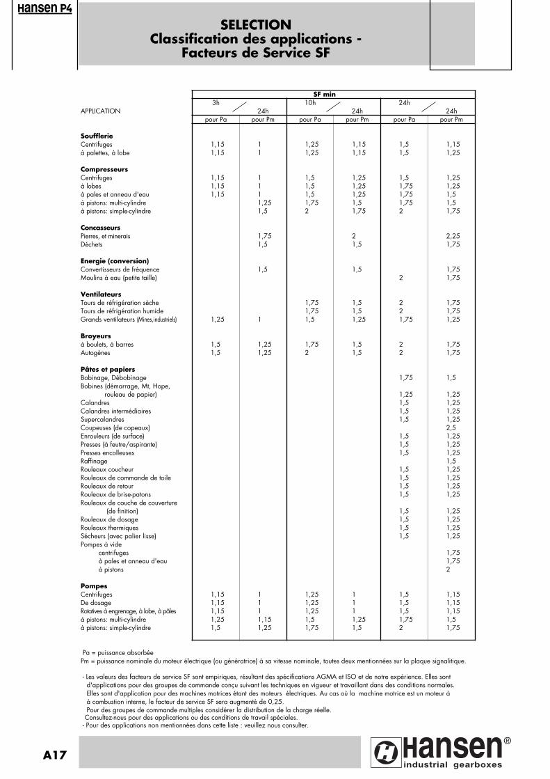
SELECTIONClassification des applications -
Facteurs de Service SF
SF min3h 10h 24h
APPLICATION 24h 24h 24hpour Pa pour Pm pour Pa pour Pm pour Pa pour Pm
SoufflerieCentrifuges 1,15 1 1,25 1,15 1,5 1,15à palettes, à lobe 1,15 1 1,25 1,15 1,5 1,25
CompresseursCentrifuges 1,15 1 1,5 1,25 1,5 1,25à lobes 1,15 1 1,5 1,25 1,75 1,25à pales et anneau d'eau 1,15 1 1,5 1,25 1,75 1,5à pistons: multi-cylindre 1,25 1,75 1,5 1,75 1,5à pistons: simple-cylindre 1,5 2 1,75 2 1,75
ConcasseursPierres, et minerais 1,75 2 2,25Déchets 1,5 1,5 1,75
Energie (conversion)Convertisseurs de fréquence 1,5 1,5 1,75Moulins à eau (petite taille) 2 1,75
VentilateursTours de réfrigération sèche 1,75 1,5 2 1,75Tours de réfrigération humide 1,75 1,5 2 1,75Grands ventilateurs (Mines,industriels) 1,25 1 1,5 1,25 1,75 1,25
Broyeursà boulets, à barres 1,5 1,25 1,75 1,5 2 1,75Autogènes 1,5 1,25 2 1,5 2 1,75
Pâtes et papiersBobinage, Débobinage 1,75 1,5Bobines (démarrage, Mt, Hope, rouleau de papier) 1,25 1,25Calandres 1,5 1,25Calandres intermédiaires 1,5 1,25Supercalandres 1,5 1,25Coupeuses (de copeaux) 2,5Enrouleurs (de surface) 1,5 1,25Presses (à feutre/aspirante) 1,5 1,25Presses encolleuses 1,5 1,25Raffinage 1,5Rouleaux coucheur 1,5 1,25Rouleaux de commande de toile 1,5 1,25Rouleaux de retour 1,5 1,25Rouleaux de brise-patons 1,5 1,25Rouleaux de couche de couverture (de finition) 1,5 1,25Rouleaux de dosage 1,5 1,25Rouleaux thermiques 1,5 1,25Sécheurs (avec palier lisse) 1,5 1,25Pompes à vide centrifuges 1,75 à pales et anneau d'eau 1,75 à pistons 2
PompesCentrifuges 1,15 1 1,25 1 1,5 1,15De dosage 1,15 1 1,25 1 1,5 1,15Rotatives à engrenage, à lobe, à pâles 1,15 1 1,25 1 1,5 1,15à pistons: multi-cylindre 1,25 1,15 1,5 1,25 1,75 1,5à pistons: simple-cylindre 1,5 1,25 1,75 1,5 2 1,75
Pa = puissance absorbéePm = puissance nominale du moteur électrique (ou génératrice) à sa vitesse nominale, toutes deux mentionnées sur la plaque signalitique.
- Les valeurs des facteurs de service SF sont empiriques, résultant des spécifications AGMA et ISO et de notre expérience. Elles sont d'applications pour des groupes de commande conçu suivant les techniques en vigueur et travaillant dans des conditions normales. Elles sont d'application pour des machines motrices étant des moteurs électriques. Au cas où la machine motrice est un moteur à à combustion interne, le facteur de service SF sera augmenté de 0,25. Pour des groupes de commande multiples considérer la distribution de la charge réelle. Consultez-nous pour des applications ou des conditions de travail spéciales. - Pour des applications non mentionnées dans cette liste : veuillez nous consulter.
A17
ansen
Pagina: 1
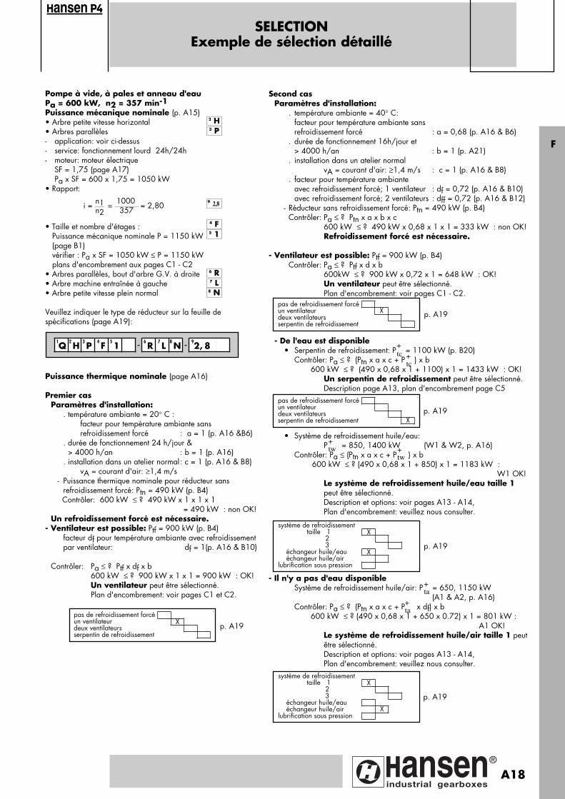
SELECTIONExemple de sélection détaillé
Second casParamètres d'installation:
. température ambiante = 40° C:facteur pour température ambiante sans refroidissement forcé : a = 0,68 (p. A16 & B6)
. durée de fonctionnement 16h/jour et > 4000 h/an : b = 1 (p. A21). installation dans un atelier normal
vA = courant d'air: ≥1,4 m/s : c = 1 (p. A16 & B8). facteur pour température ambiante
avec refroidissement forcé; 1 ventilateur : df = 0,72 (p. A16 & B10)avec refroidissement forcé; 2 ventilateurs : dff = 0,72 (p. A16 & B12)
- Réducteur sans refroidissement forcé: Ptn = 490 kW (p. B4) Contrôler: Pa ≤ ? Ptn x a x b x c 600 kW ≤ ? 490 kW x 0,68 x 1 x 1 = 333 kW : non OK!
Refroidissement forcé est nécessaire.
- Ventilateur est possible: Ptf = 900 kW (p. B4) Contrôler: Pa ≤ ? Ptf x d x b 600kW ≤ ? 900 kW x 0,72 x 1 = 648 kW : OK!
Un ventilateur peut être sélectionné. Plan d'encombrement: voir pages C1 - C2.
- De l'eau est disponible• Serpentin de refroidissement: P = 1100 kW (p. B20) Contrôler: Pa ≤ ? (Ptn x a x c + P ) x b
600 kW ≤ ? (490 x 0,68 x 1 + 1100) x 1 = 1433 kW : OK! Un serpentin de refroidissement peut être sélectionné. Description page A13, plan d'encombrement page C5
• Système de refroidissement huile/eau:
P = 850, 1400 kW (W1 & W2, p. A16) Contrôler: Pa ≤ (Ptn x a x c + P ) x b
600 kW ≤ ? (490 x 0,68 x 1 + 850) x 1 = 1183 kW : W1 OK!
Le système de refroidissement huile/eau taille 1 peut être sélectionné. Description et options: voir pages A13 - A14,
Plan d'encombrement: veuillez nous consulter.
- Il n'y a pas d'eau disponible Système de refroidissement huile/air: P = 650, 1150 kW
(A1 & A2, p. A16) Contrôler: Pa ≤ ? (Ptn x a x c + P x df) x b 600 kW ≤ ? (490 x 0,68 x 1 + 650 x 0.72) x 1 = 801 kW :
A1 OK!Le système de refroidissement huile/air taille 1 peutêtre sélectionné.Description et options: voir pages A13 - A14, Plan d'encombrement: veuillez nous consulter.
p. A19
p. A19
système de refroidissement taille 1 X 2 3 échangeur huile/eau X échangeur huile/airlubrification sous pression
+tc +
tc
+tw
p. A19
Puissance thermique nominale (page A16)
Premier casParamètres d'installation:
. température ambiante = 20° C : facteur pour température ambiante sans
refroidissement forcé : a = 1 (p. A16 &B6). durée de fonctionnement 24 h/jour & > 4000 h/an : b = 1 (p. A16). installation dans un atelier normal: c = 1 (p. A16 & B8)
vA = courant d'air: ≥1,4 m/s- Puissance thermique nominale pour réducteur sans
refroidissement forcé: Ptn = 490 kW (p. B4) Contrôler: 600 kW ≤ ? 490 kW x 1 x 1 x 1
= 490 kW : non OK!Un refroidissement forcé est nécessaire.
- Ventilateur est possible: Ptf = 900 kW (p. B4) facteur df pour température ambiante avec refroidissement
par ventilateur: df = 1(p. A16 & B10)
Contrôler: Pa ≤ ? Ptf x df x b 600 kW ≤ ? 900 kW x 1 x 1 = 900 kW : OK!
Un ventilateur peut être sélectionné. Plan d'encombrement: voir pages C1 et C2.
p. A19pas de refroidissement forcéun ventilateur Xdeux ventilateursserpentin de refroidissement
p. A19
+ta
+ta
Pompe à vide, à pales et anneau d'eauPa = 600 kW, n2 = 357 min-1Puissance mécanique nominale (p. A15)• Arbre petite vitesse horizontal• Arbres parallèles- application: voir ci-dessus- service: fonctionnement lourd 24h/24h- moteur: moteur électrique SF = 1,75 (page A17)
Pa x SF = 600 x 1,75 = 1050 kW• Rapport:
• Taille et nombre d'étages : Puissance mécanique nominale P = 1150 kW (page B1) vérifier : Pa x SF = 1050 kW ≤ P = 1150 kW plans d'encombrement aux pages C1 - C2• Arbres parallèles, bout d'arbre G.V. à droite• Arbre machine entraînée à gauche• Arbre petite vitesse plein normal
Veuillez indiquer le type de réducteur sur la feuille despécifications (page A19):
n1 1000n2 357i = = = 2,80
7 L8 N
6 R
4 F
9 2,8
3 P
2 H
5 1
1Q
2 H
3 P
4 F
5 1 - 6
R 7 L
8 N -
92, 8
pas de refroidissement forcéun ventilateur Xdeux ventilateursserpentin de refroidissement
pas de refroidissement forcéun ventilateurdeux ventilateursserpentin de refroidissement X
+tw
système de refroidissement taille 1 X 2 3 échangeur huile/eau échangeur huile/air Xlubrification sous pression
F
ansen
A18
Pagina: 1
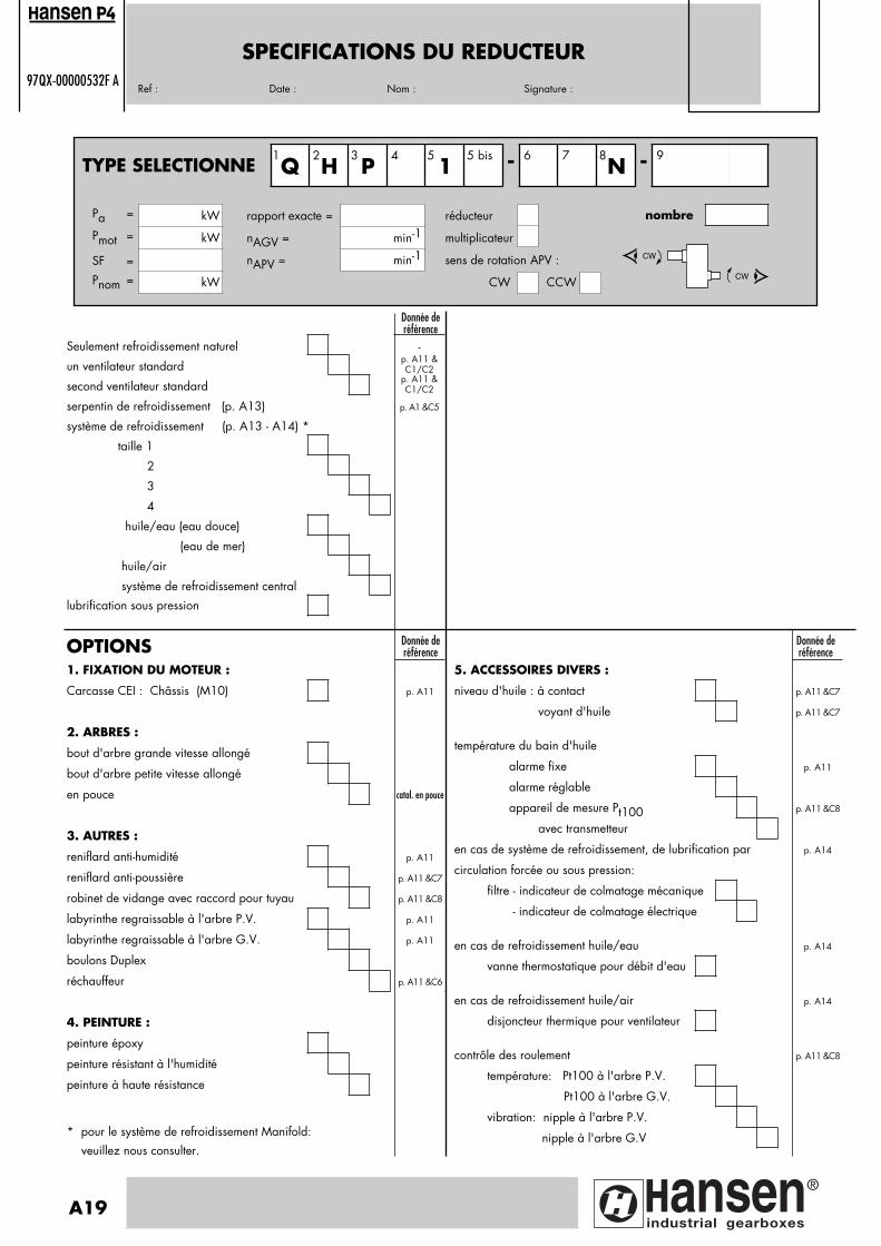
SPECIFICATIONS DU REDUCTEUR97QX-00000532F A
Ref : Date : Nom : Signature :
1. FIXATION DU MOTEUR :
Carcasse CEI : Châssis (M10) p. A11
2. ARBRES :
bout d'arbre grande vitesse allongé
bout d'arbre petite vitesse allongé
en pouce catal. en pouce
3. AUTRES :
reniflard anti-humidité p. A11
reniflard anti-poussière p. A11 &C7
robinet de vidange avec raccord pour tuyau p. A11 &C8
labyrinthe regraissable à l'arbre P.V. p. A11
labyrinthe regraissable à l'arbre G.V. p. A11
boulons Duplex
réchauffeur p. A11 &C6
4. PEINTURE :
peinture époxy
peinture résistant à l'humidité
peinture à haute résistance
* pour le système de refroidissement Manifold: veuillez nous consulter.
OPTIONS Donnée deréférence
Donnée deréférence
Seulement refroidissement naturel -
un ventilateur standardp. A11 &C1/C2
second ventilateur standardp. A11 &C1/C2
serpentin de refroidissement (p. A13) p. A1 &C5
système de refroidissement (p. A13 - A14) *
taille 1
2
3
4
huile/eau (eau douce)
(eau de mer)
huile/air
système de refroidissement central
lubrification sous pression
Donnée deréférence
5. ACCESSOIRES DIVERS :
niveau d'huile : à contact p. A11 &C7
voyant d'huile p. A11 &C7
température du bain d'huile
alarme fixe p. A11
alarme réglable
appareil de mesure Pt100 p. A11 &C8
avec transmetteur
en cas de système de refroidissement, de lubrification par p. A14
circulation forcée ou sous pression:
filtre - indicateur de colmatage mécanique
- indicateur de colmatage électrique
en cas de refroidissement huile/eau p. A14
vanne thermostatique pour débit d'eau
en cas de refroidissement huile/air p. A14
disjoncteur thermique pour ventilateur
contrôle des roulement p. A11 &C8
température: Pt100 à l'arbre P.V.
Pt100 à l'arbre G.V.
vibration: nipple à l'arbre P.V.
nipple à l'arbre G.V
A19
ansen
TYPE SELECTIONNE Q H P4
15 bis - 6 7
N - 9
CW
CW
1 2 3 5 8
Pa = kW rapport exacte = réducteur
Pmot = kW nAGV = min-1 multiplicateur
SF = nAPV = min-1 sens de rotation APV :
Pnom = kW CW CCW
nombre
Pagina: 1
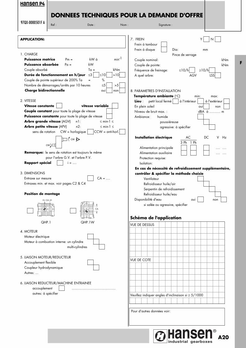
DONNEES TECHNIQUES POUR LA DEMANDE D'OFFRE97QX-0000501F A
Ref : Date : Nom : Signature :
APPLICATION:
1. CHARGE Puissance motrice Pm = kW à min-1
Puissance absorbée Pa = kW Couple absorbé Ta = kNm Durée de fonctionnement en h/jour ≤3 ≤10 >10 Couple de pointe supérieur de 200% Ta = % Nombre de démarrages/arrêts par 10 heures ≤5 >5 Charge bidirectionnelle oui non
2. VITESSE Vitesse constante vitesse variable Couple constant pour toute la plage de vitesse Puissance constante pour toute la plage de vitesse Arbre grande vitesse (AGV) n1: ≤ min-1 ≤ Arbre petite vitesse (APV) n2: ≤ min-1 ≤ sens de rotation CW = horlogique CCW = anti-horl.
Remarque: le sens de rotation est toujours le même pour l'arbre G.V. et l'arbre P.V. Rapport spécial i = ....
3. DIMENSIONS Entraxe sur mesure CA = .... Entraxes min. et max. voir pages C2 & C4
Position de montage
4. MOTEUR Moteur électrique Moteur à combustion interne: un cylindre multi-cylindres
5. LIAISON MOTEUR/REDUCTEUR Accouplement flexible Coupleur hydrodynamique Autres: ...
6. LIAISON REDUCTEUR/MACHINE ENTRAINEE accouplement ........................................... autres: à spécifier
Schéma de l'applicationVUE DE DESSUS
VUE DE COTE
Veuillez indiquer angles d'inclinaison si ≥ 5/1000
7. FREIN Y N Frein à tambour Frein à disque Dia: mm Pince de serrage Couple nominal: kNm Couple de pointe: kNm Fréquence de freinage: ≤10/h ≥10/h A quel arbre: AGV LSS
8. PARAMETRES D'INSTALLATION Température ambiante (°C) min: max: Lieu : petit local fermé à l'intérieur à l'extérieur En plein soleil oui non Niveau de bruit max. : dBA à ........... m Ambiance: humide poussiéreuse agressive: à spécifier
Installation électrique AC DC V Hz 3 Ph 1 Ph Alimentation principale .... .... Alimentation auxiliaire .... .... Protection requise: Isolation: En cas de nécessité de refroidissement supplémentaire, contrôler & spécifier la méthode choisie Ventilateur Refroidisseur huile/air Serpentin de refroidissement Refroidisseur huile/eau Disponibilité d'eau oui non si salée ou agressive, spécifier
Pour d'autres données voir:
CW
CW
ansen
F
CA
CA
QHP.1 QHP.1W
A20
Pagina: 1

STANDARD- MESS- UND ANZEIGEGERÄTE
UND OPTIONEN FÜR GETRIEBE
ansen
1 Ölmeßstab2 Entlüftungsschraube3 Ölstandglas4 Ölstandschalter5 Ablaß- und Magnetschraube6 Ölablaßhahn mit Rohranschluß7 Meßapparat Pt 100 für Ölbadtemperatur8 Ölüberflußrohr9 Heizstab (am Hilfsdeckel)
10 Kühlschlange (am Hilfsdeckel)11 Öleinfüllschraube12 Entlüftungsschraube für feuchte Umgebung13 Entlüftungsschraube mit Staubfilter14 Nachschmierbares Labyrinth (DIN 71412):
an der schnelldrehenden Wellean der langsamdrehenden Welle
15 Standardlüfter:ein Standardlüfter an der schnelldrehenden Wellezweiter Standardlüfter an der langsamdrehenden Welle
16 eine verlängerte Wellean der schnelldrehenden Wellean der langsamdrehenden Welle
17 Oil-LockTM Dichtung an der schnell- und langsamdrehenden Welle18 Nippel für Schwingungsfühler
an der schnelldrehenden Wellean der langsamdrehenden Welle
19 Meßapparat Pt 100 für Lagertemperaturan der schnelldrehenden Wellean der langsamdrehenden Welle
20 Fundamentrahmen M10
: Option
A21
OIL-LOCKTM
t°
1
2
4Option
3Option
5
6Option
t°
7Option
8Option
10Option
8 Option7Option 6
Option
5
2
1
11
13 Option
15
16
18191112Option13Option
20Option 20Option
10Option
t°���
����
���
��
��
��
���
�
��
�
��
�����
�
�
�
�
�
����
��
�
�
14
12 Option
4Option
3Option
Option
Option Option
Option
9Option
Option
17
Pagina: 1
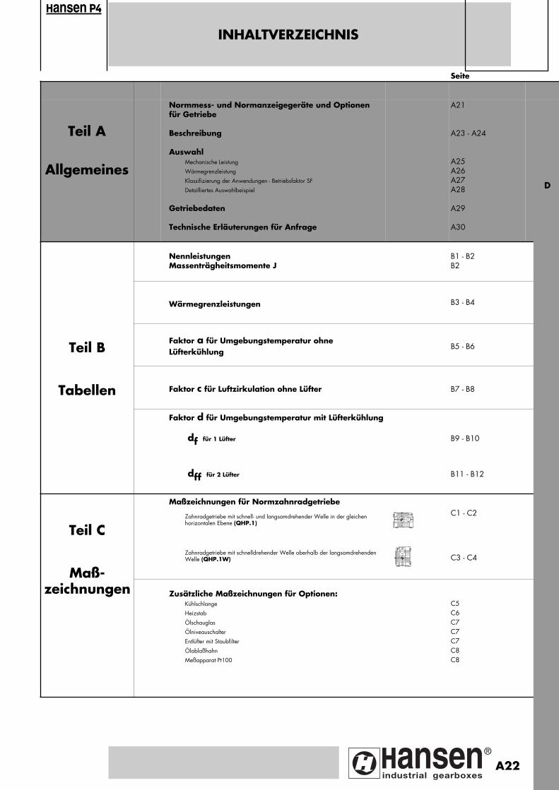
Seite
Teil A
Allgemeines
Normmess- und Normanzeigegeräte und Optionenfür Getriebe
Beschreibung
AuswahlMechanische Leistung
Wärmegrenzleistung
Klassifizierung der Anwendungen - Betriebsfaktor SF
Detailliertes Auswahlbeispiel
Getriebedaten
Technische Erläuterungen für Anfrage
A21
A23 - A24
A25 A26A27A28
A29
A30
NennleistungenMassenträgheitsmomente J
B1 - B2B2
Wärmegrenzleistungen B3 - B4
Teil BFaktor a für Umgebungstemperatur ohne Lüfterkühlung
B5 - B6
Tabellen Faktor c für Luftzirkulation ohne Lüfter B7 - B8
Faktor d für Umgebungstemperatur mit Lüfterkühlung
df für 1 Lüfter B9 - B10
dff für 2 Lüfter B11 - B12
Teil C
Maßzeichnungen für Normzahnradgetriebe
Zahnradgetriebe mit schnell- und langsamdrehender Welle in der gleichen horizontalen Ebene (QHP.1)
C1 - C2
Maß-
Zahnradgetriebe mit schnelldrehender Welle oberhalb der langsamdrehenden Welle (QHP.1W) C3 - C4
zeichnungen
Zusätzliche Maßzeichnungen für Optionen: Kühlschlange
Heizstab
Ölschauglas
Ölniveauschalter
Entlüfter mit Staubfilter
Ölablaßhahn
Meßapparat Pt100
C5C6C7C7C7C8C8
INHALTVERZEICHNIS
ansen
D
A22
Pagina: 1
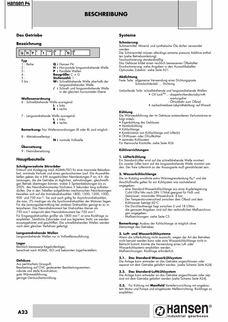
BESCHREIBUNG
Das Getriebe
Bezeichnung
Typ1 : Reihe Q : Hansen P42 : H : Horizontale langsamdrehende Welle3 : P : Parallele Wellen4 : Baugröße: C -> G5 : Stufenzahl: 15 bis : W: Schnelldrehende Welle oberhalb der
langsamdrehenden Welle/ : Schnell- und langsamdrehende Welle
in der gleichen horizontalen Ebene
Wellenanordnung6 : Schnelldrehende Welle ausragend:
L : linksR : rechts
7 : Langsamdrehende Welle ausragend:L : linksR : rechts
Bemerkung: Nur Wellenanordnungen LR oder RL sind möglich.
8 : Abtriebswellentyp :N : normale Vollwelle
Übersetzung9 : Nennübersetzung
Hauptbauteile
Schrägverzahnte StirnräderEntwurf und Auslegung nach AGMA/ISO für eine maximale Belastbar-keit, minimale Verluste und einen geräuscharmen Lauf. Die Auswahlta-bellen geben die in kW ausgedrückten Nennleistungen P an, d.h. dieLeistungen, die die Getriebe im täglichen, zehnstündigen, gleichmäßi-gen Betrieb übertragen können, wobei 5 Spitzenbelastungen bis zu200% des Nenndrehmomentes höchstens 5 Sekunden lang auftretendürfen. Die in den Tabellen aufgeführten mechanischen Nennleistungenbeziehen sich auf die Antriebsdrehzahlen 1800, 1500, 1200, 1000,900 und 750 min-1. Sie sind auch gültig für Asynchrondrehzahlen,die max. 3% niedriger als die Synchrondrehzahlen der Motoren liegen.Für die Leistungsübermittlung bei anderen Drehzahlen genügt es zu in-terpolieren. Das Nenndrehmoment bei Drehzahlen kleiner als 750 min-1 entspricht dem Nenndrehmoment bei 750 min-1.Für Eingangsdrehzahlen größer als 1800 min-1 ist eine Rückfrage zuempfehlen. Sämtliche Zahnräder sind aus legiertem Stahl; sie werdeneinsatzgehärtet und geschliffen. Die schnelldrehenden Wellen werdennach dem gleichen Verfahren gefertigt. Langsamdrehende WellenLangsamdrehende Wellen nur in Vollwellenausführung.
LagerReichlich bemessene Kegelrollenlager,berechnet nach AGMA, ISO und bekannten Lagerherstellern.
GehäuseAus perlitischem Grauguß;Bearbeitung auf CNC gesteuerten Bearbeitungszentren; robuste und steife Konstruktion;gute Wärmeabführung;geringe Geräuschentwicklung.
Systeme
SchmierungSchmiermittel: Mineral- und synthetische Öle dürfen verwendet werden. Die Schmiermittel müssen allerdings extreme pressure Additive enthal-ten (siehe Betriebsanleitung).Tauchschmierung standardmäßigDas Gehäuse bildet einen reichlich bemessenen ÖlbehälterDruckschmierung: siehe Angaben in den AuswahltabellenOptionales Zubehör: siehe Seite A21
AbdichtungFeste Teile: allgemeine Verwendung einer Dichtungspaste
Schaulochdeckel: ... Dichtung
Umlaufende Teile: schnelldrehende und langsamdrehende Wellen:• Oil LockTM : - doppelwirkendes-Labyrinth
- wartungsfrei- Ölrückkehr zum Ölbad
• nachschmierbare Labyrinthdichtung: auf Wunsch
Kühlung Die Wärmeabführung der im Gehäuse entstandenen Verlustwärme er-folgt mittels:• Eigenkühlung des Gehäuses• Ventilorkühlung• Kühlschlange• Kombination von Kühlschlange und Lüfter(n)• Öl-Wasser- oder Öl-Luftkühler• zentrales KühlsystemFür thermische Kontrolle: siehe Seite A26
Kühlvorrichtungen
1. LüfterkühlungEin Standard-Lüfter wird auf die schnelldrehende Welle montiert.Ein zweiter Lüfter kann auf die langsamdrehende Welle montiert wer-den. Der freie Lufteintritt an der Ansaugseite muß gewährleistet sein.
2. WasserkühlschlangeDie im Katalog erwähnte extra Wärmegrenzleistung Ptc+ und dieAnschlußmaße gelten für ein Kühlsystem wie nachstehendangegeben:
- eine Standard-Wasserkühlschlange aus einer Kupferlegierung CuNi10Fe1Mn nach DIN 17664 geeignet für Fluß- undSeewasser; maximaler Wasserdruck: 8 bar
- Der Temperaturunterschied zwischen dem Ölbad und dem Kühlwasser beträgt 60°C.
- Die Durchlaufmenge liegt zwischen 5 und 18 l/Min; die genauen Angaben sind auf den verbindlichen Maßzeichnun-gen angegeben.
- Maßzeichnungen: siehe Seite C5.
Bemerkung: Ausbau der Kühlschlange ist möglich ohne Demontage des Getriebes.
3. Luft- und WasserkühlsystemeWenn die Lüfterkühlung nicht ausreicht, wegen der Art des Betriebesnicht benutzt werden kann oder eine Wasserkühlschlange nicht inBetracht kommt, könnte die Verwendung eines Luft- oderWasserkühlsystems empfohlen werden.Maßzeichnungen: Rückfrage erforderlich
3.1. Das Standard-WasserkühlsystemDie Anlage kann entweder an das Getriebe angeschlossen oderseparat mit dem Getriebe geliefert werden. (siehe Schema Seite A24)
3.2. Das Standard-LuftkühlsystemDie Anlage kann entweder an das Getriebe angeschlossen oder sep-arat mit dem Getriebe geliefert werden (siehe Schema Seite A24).
3.3. Für Kühlung mit Manifold Verteilervorrichtung mit angebau-tem Motor und Pumpe und eingebauter Meßeinrichtung, Rückfrage zuempfehlen.
1Q
2H
3P
4 51
5 bis - 6 7 8N - 9
ansen
A23
Pagina: 1
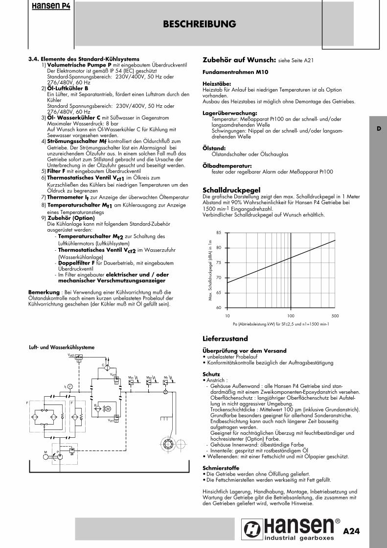
BESCHREIBUNG
3.4. Elemente des Standard-Kühlsystems1) Volumetrische Pumpe P mit eingebautem Überdruckventil
Der Elektromotor ist gemäß IP 54 (IEC) geschütztStandard-Spannungsbereich: 230V/400V, 50 Hz oder 276/480V, 60 Hz
2) Öl-Luftkühler BEin Lüfter, mit Separatantrieb, fördert einen Luftstrom durch denKühlerStandard Spannungsbereich: 230V/400V, 50 Hz oder 276/480V, 60 Hz
3) Öl- Wasserkühler C mit Süßwasser in GegenstromMaximaler Wasserdruck: 8 barAuf Wunsch kann ein Öl-Wasserkühler C für Kühlung mit Seewasser vorgesehen werden.
4) Strömungsschalter Mf kontrolliert den Öldurchfluß zum Getriebe. Der Strömungsschalter löst ein Alarmsignal beiunzureichendem Ölzufuhr aus. In einem solchen Fall muß das Getriebe sofort zum Stillstand gebracht und die Ursache der Unterbrechung in der Ölzufuhr gesucht und beseitigt werden.
5) Filter F mit eingebautem Überdruckventil6) Thermostatisches Ventil Vct1 im Ölkreis zum
Kurzschließen des Kühlers bei niedrigen Temperaturen um den Öldruck zu begrenzen
7) Thermometer It zur Anzeige der überwachten Öltemperatur8) Temperaturschalter Mt1 am Kühlerausgang zur Anzeige
eines Temperaturanstiegs9) Zubehör (Option)
Die Kühlanlage kann mit folgendem Standard-Zubehörausgerüstet werden:
- Temperaturschalter Mt2 zur Schaltung des Luftkühlermotors (Luftkühlsystem)
- Thermostatisches Ventil Vct2 im Wasserzufuhr (Wasserkühlanlage)
- Doppelfilter F für Dauerbetrieb, mit eingebautem Überdruckventil
- Im Filter eingebauter elektrischer und / oder mechanischer Verschmutzungsanzeiger
Bemerkung : Bei Verwendung einer Kühlvorrichtung muß dieÖlstandskontrolle nach einem kurzen unbelasteten Probelauf derKühlvorrichtung geschehen (der Kühler muß mit Öl gefüllt sein).
Zubehör auf Wunsch: siehe Seite A21
Fundamentrahmen M10
Heizstäbe:Heizstab für Anlauf bei niedrigen Temperaturen ist als Optionvorhanden.Ausbau des Heizstabes ist möglich ohne Demontage des Getriebes.
Lagerüberwachung:Temperatur: Meßapparat Pt100 an der schnell- und/oder langsamdrehenden WelleSchwingungen: Nippel an der schnell- und/oder langsam-drehenden Welle
Ölstand: Ölstandschalter oder Ölschauglas
Ölbadtemperatur:fester oder regelbarer Alarm oder Meßapparat Pt100
SchalldruckpegelDie grafische Darstellung zeigt den max. Schalldruckpegel in 1 MeterAbstand mit 90% Wahrscheinlichkeit für Hansen P4 Getriebe bei1500 min-1 Eingangsdrehzahl.Verbindlicher Schalldruckpegel auf Wunsch erhältlich.
Lieferzustand
Überprüfung vor dem Versand• unbelasteter Probelauf• Konformitätskontrolle bezüglich der Auftragsbestätigung
Schutz• Anstrich :
- Gehäuse Außenwand : alle Hansen P4 Getriebe sind stan-dardmäßig mit einem Zweikomponenten-Epoxydanstrich versehen.Oberflächenschutz : langjähriger Oberflächenschutz bei Aufstel-lung in nicht aggressiver Umgebung.Trockenschichtdicke : Mittelwert 100 µm (inklusive Grundanstrich).Grundfarbe besonders geeignet für allerhand Sonderanstriche. Endbeschichtung kann auch nach längerer Zeit bauseitig aufgetragen werden.Geeignet für nachträglichen Überzug mit feuchtbeständiger und hochresistenter (Option) Farbe.
- Gehäuse Innenwand: ölbeständige Farbe- Innenteile: gespritzt mit rostbeständigem Öl
• Wellenenden: mit einer Fettschicht und mit Ölpapier geschützt.
Schmierstoffe• Die Getriebe werden ohne Ölfüllung geliefert.• Die Fettschmierstellen werden werkseitig mit Fett gefüllt.
Hinsichtlich Lagerung, Handhabung, Montage, Inbetriebsetzung undWartung der Getriebe gibt die Betriebsanleitung, die zusammen mitden Getrieben geliefert wird, wertvolle Hinweise.
ansen
F
M P
F
It t°
B
t°
Vct1
C
Vct2
Mt1 Mf
M
Vct1 t°
Mt2
t°
Luft- und Wasserkühlsysteme
10 100
60
65
70
75
80
85
Pa (Abtriebsleistung kW) für SF≤2,5 und n1=1500 min-1
Max
. Sch
alld
ruck
pege
l (dB
A) i
n 1m
500
D
A24
Pagina: 1
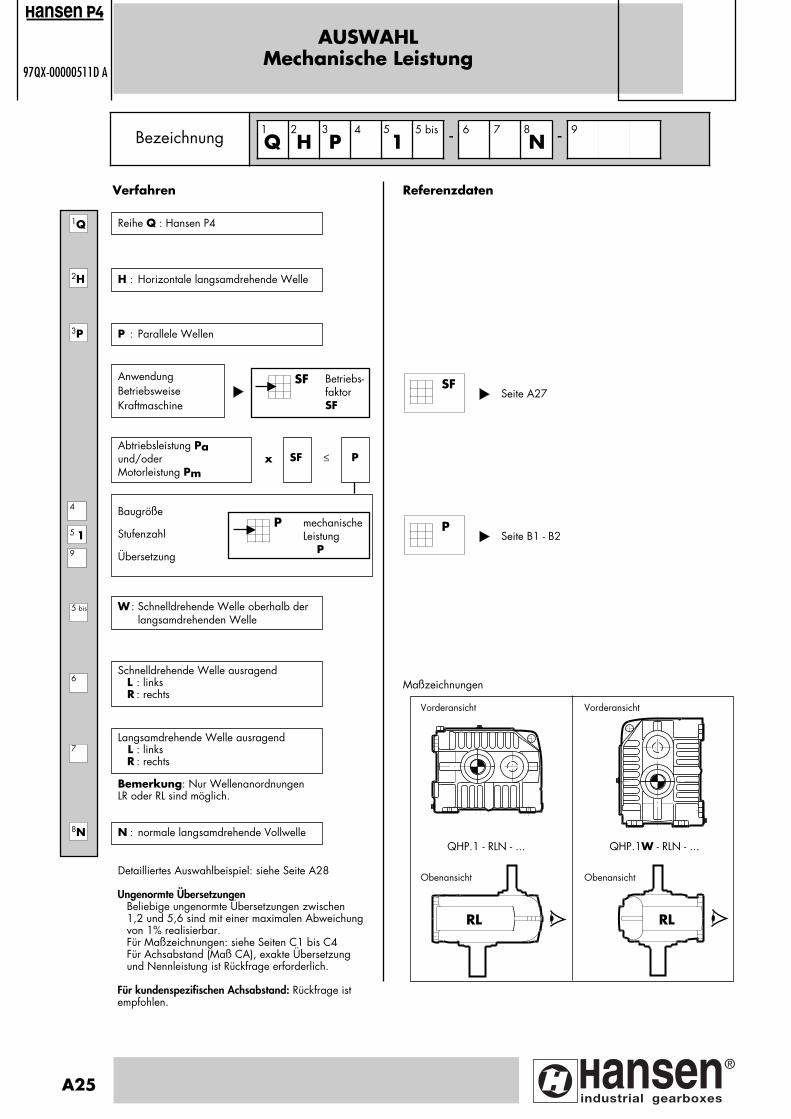
Betriebs-faktorSF
AUSWAHLMechanische Leistung
97QX-00000511D A
H : Horizontale langsamdrehende Welle
Referenzdaten
AnwendungBetriebsweiseKraftmaschine
SF
Baugröße
Stufenzahl
Übersetzung
mechanischeLeistung P
P
Abtriebsleistung Pa und/oderMotorleistung Pm
SF P x ≤
Schnelldrehende Welle ausragend L : links R : rechts
Langsamdrehende Welle ausragend L : links
R : rechts
Seite A27
Maßzeichnungen
Bezeichnung Q H P4
15 bis - 6 7
N - 9
2H
3P
5 19
4
7
8N
6
SF
Verfahren
Reihe Q : Hansen P41Q
1
5 bis
A25
2 3 5 8
P : Parallele Wellen
W : Schnelldrehende Welle oberhalb der langsamdrehenden Welle
Bemerkung: Nur WellenanordnungenLR oder RL sind möglich.
N : normale langsamdrehende Vollwelle
Detailliertes Auswahlbeispiel: siehe Seite A28
Vorderansicht Vorderansicht
QHP.1 - RLN - ... QHP.1W - RLN - ...
RL RL
Obenansicht Obenansicht
ansen
Ungenormte ÜbersetzungenBeliebige ungenormte Übersetzungen zwischen 1,2 und 5,6 sind mit einer maximalen Abweichungvon 1% realisierbar.Für Maßzeichnungen: siehe Seiten C1 bis C4Für Achsabstand (Maß CA), exakte Übersetzung und Nennleistung ist Rückfrage erforderlich.
Für kundenspezifischen Achsabstand: Rückfrage istempfohlen.
Seite B1 - B2P
Pagina: 1
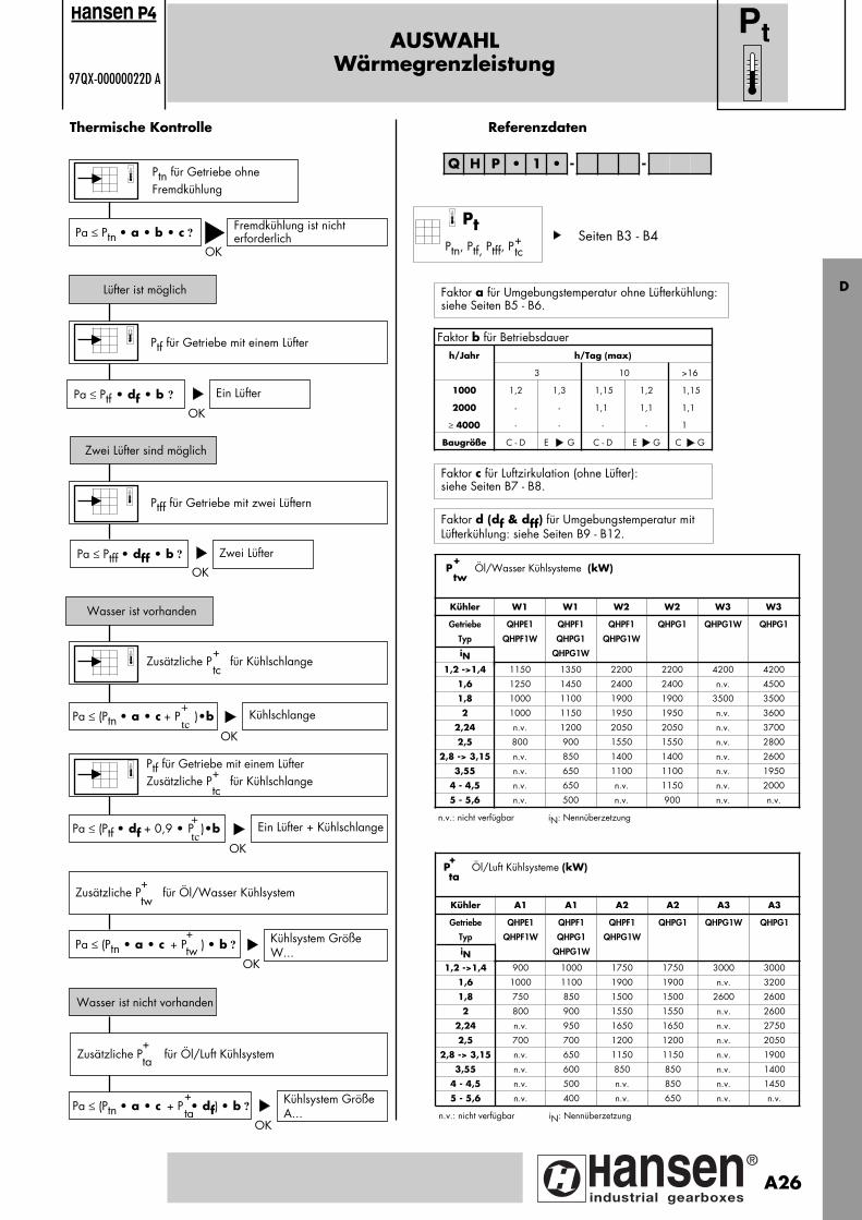
AUSWAHLWärmegrenzleistung
97QX-00000022D A
Ptn für Getriebe ohneFremdkühlung
OK
Thermische Kontrolle
Pa ≤ Ptn • a • b • c ?
Lüfter ist möglich
Fremdkühlung ist nicht erforderlich
Ptf für Getriebe mit einem Lüfter
Pa ≤ Ptf • df • b ?
Zwei Lüfter sind möglich
Ein Lüfter
Ptff für Getriebe mit zwei Lüftern
Pa ≤ Ptff • dff • b ?
Wasser ist vorhanden
Zwei Lüfter
Zusätzliche P für Kühlschlange
Pa ≤ (Ptn • a • c + P )•b Kühlschlange
Pa ≤ (Ptn • a • c + P ) • b ? Kühlsystem GrößeW...
Referenzdaten
Pa ≤ (Ptn • a • c + P • df) • b ?Kühlsystem GrößeA...
Wasser ist nicht vorhanden
Zusätzliche P für Öl/Luft Kühlsystem
Zusätzliche P für Öl/Wasser Kühlsystem+tw
+tw
+ta
+ta
OK
OK
OK
OK
OK
+tc
+
tc
Q H P • 1 • - -
Pt
Faktor a für Umgebungstemperatur ohne Lüfterkühlung:siehe Seiten B5 - B6.
Faktor c für Luftzirkulation (ohne Lüfter):siehe Seiten B7 - B8.
Faktor d (df & dff) für Umgebungstemperatur mit Lüfterkühlung: siehe Seiten B9 - B12.
Ptf für Getriebe mit einem LüfterZusätzliche P für Kühlschlange
+tc
Pa ≤ (Ptf • df + 0,9 • P )•b Ein Lüfter + Kühlschlange
OK
+
tc
ansen
Pt
Ptn, Ptf, Ptff, P+tc
D
Seiten B3 - B4
Faktor b für Betriebsdauerh/Jahr h/Tag (max)
3 10 >16
1000 1,2 1,3 1,15 1,2 1,15
2000 - - 1,1 1,1 1,1
≥ 4000 - - - - 1
Baugröße C - D E G C - D E G C G
Kühler W1 W1 W2 W2 W3 W3
Getriebe
Typ
iN
QHPE1
QHPF1W
QHPF1
QHPG1
QHPG1W
QHPF1
QHPG1W
QHPG1 QHPG1W QHPG1
1,2 ->1,4 1150 1350 2200 2200 4200 4200
1,6 1250 1450 2400 2400 n.v. 4500
1,8 1000 1100 1900 1900 3500 3500
2 1000 1150 1950 1950 n.v. 3600
2,24 n.v. 1200 2050 2050 n.v. 3700
2,5 800 900 1550 1550 n.v. 2800
2,8 -> 3,15 n.v. 850 1400 1400 n.v. 2600
3,55 n.v. 650 1100 1100 n.v. 1950
4 - 4,5 n.v. 650 n.v. 1150 n.v. 2000
5 - 5,6 n.v. 500 n.v. 900 n.v. n.v.
n.v.: nicht verfügbar iN: Nennüberzetzung
P Öl/Wasser Kühlsysteme (kW)+
tw
Kühler A1 A1 A2 A2 A3 A3
Getriebe
Typ
iN
QHPE1
QHPF1W
QHPF1
QHPG1
QHPG1W
QHPF1
QHPG1W
QHPG1 QHPG1W QHPG1
1,2 ->1,4 900 1000 1750 1750 3000 3000
1,6 1000 1100 1900 1900 n.v. 3200
1,8 750 850 1500 1500 2600 2600
2 800 900 1550 1550 n.v. 2600
2,24 n.v. 950 1650 1650 n.v. 2750
2,5 700 700 1200 1200 n.v. 2050
2,8 -> 3,15 n.v. 650 1150 1150 n.v. 1900
3,55 n.v. 600 850 850 n.v. 1400
4 - 4,5 n.v. 500 n.v. 850 n.v. 1450
5 - 5,6 n.v. 400 n.v. 650 n.v. n.v.
n.v.: nicht verfügbar iN: Nennüberzetzung
P Öl/Luft Kühlsysteme (kW)+
ta
A26
Pagina: 1
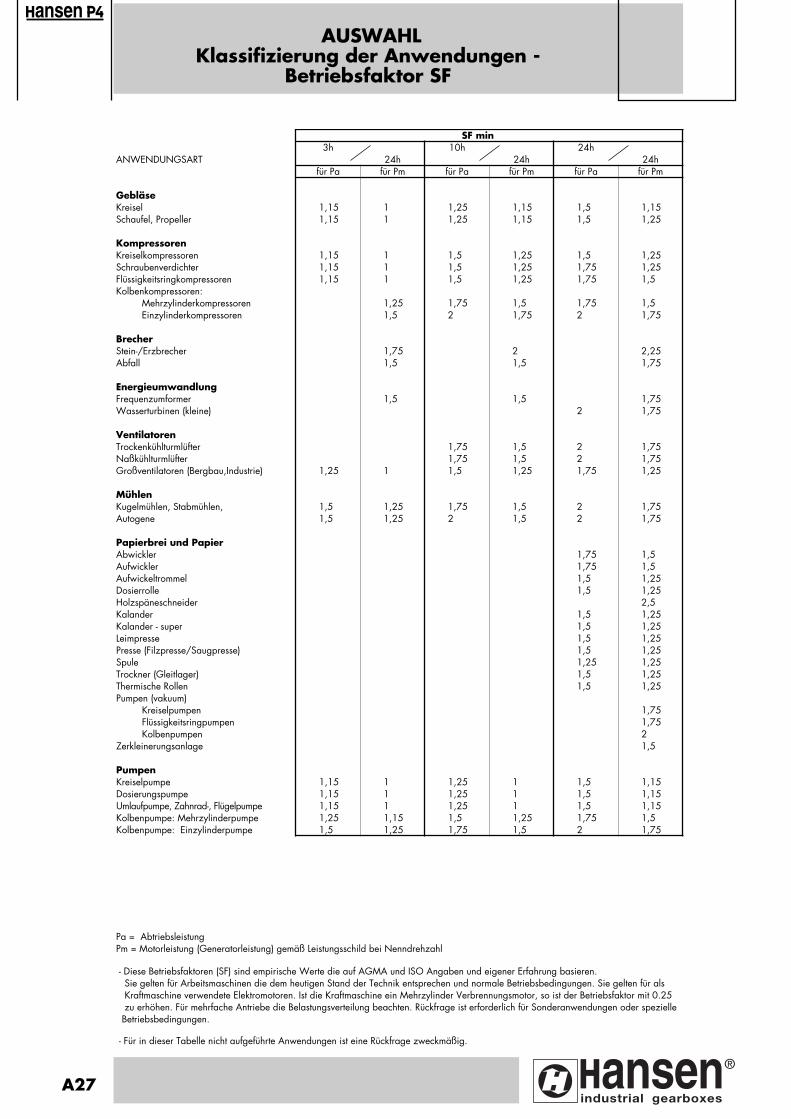
AUSWAHLKlassifizierung der Anwendungen -
Betriebsfaktor SF
SF min3h 10h 24h
ANWENDUNGSART 24h 24h 24hfür Pa für Pm für Pa für Pm für Pa für Pm
GebläseKreisel 1,15 1 1,25 1,15 1,5 1,15Schaufel, Propeller 1,15 1 1,25 1,15 1,5 1,25
KompressorenKreiselkompressoren 1,15 1 1,5 1,25 1,5 1,25Schraubenverdichter 1,15 1 1,5 1,25 1,75 1,25Flüssigkeitsringkompressoren 1,15 1 1,5 1,25 1,75 1,5Kolbenkompressoren: Mehrzylinderkompressoren 1,25 1,75 1,5 1,75 1,5 Einzylinderkompressoren 1,5 2 1,75 2 1,75
BrecherStein-/Erzbrecher 1,75 2 2,25Abfall 1,5 1,5 1,75
EnergieumwandlungFrequenzumformer 1,5 1,5 1,75Wasserturbinen (kleine) 2 1,75
VentilatorenTrockenkühlturmlüfter 1,75 1,5 2 1,75Naßkühlturmlüfter 1,75 1,5 2 1,75Großventilatoren (Bergbau,Industrie) 1,25 1 1,5 1,25 1,75 1,25
MühlenKugelmühlen, Stabmühlen, 1,5 1,25 1,75 1,5 2 1,75Autogene 1,5 1,25 2 1,5 2 1,75
Papierbrei und PapierAbwickler 1,75 1,5Aufwickler 1,75 1,5Aufwickeltrommel 1,5 1,25Dosierrolle 1,5 1,25Holzspäneschneider 2,5Kalander 1,5 1,25Kalander - super 1,5 1,25Leimpresse 1,5 1,25Presse (Filzpresse/Saugpresse) 1,5 1,25Spule 1,25 1,25Trockner (Gleitlager) 1,5 1,25Thermische Rollen 1,5 1,25Pumpen (vakuum) Kreiselpumpen 1,75 Flüssigkeitsringpumpen 1,75 Kolbenpumpen 2Zerkleinerungsanlage 1,5
PumpenKreiselpumpe 1,15 1 1,25 1 1,5 1,15Dosierungspumpe 1,15 1 1,25 1 1,5 1,15Umlaufpumpe, Zahnrad-, Flügelpumpe 1,15 1 1,25 1 1,5 1,15Kolbenpumpe: Mehrzylinderpumpe 1,25 1,15 1,5 1,25 1,75 1,5Kolbenpumpe: Einzylinderpumpe 1,5 1,25 1,75 1,5 2 1,75
Pa = AbtriebsleistungPm = Motorleistung (Generatorleistung) gemäß Leistungsschild bei Nenndrehzahl
- Diese Betriebsfaktoren (SF) sind empirische Werte die auf AGMA und ISO Angaben und eigener Erfahrung basieren. Sie gelten für Arbeitsmaschinen die dem heutigen Stand der Technik entsprechen und normale Betriebsbedingungen. Sie gelten für als Kraftmaschine verwendete Elektromotoren. Ist die Kraftmaschine ein Mehrzylinder Verbrennungsmotor, so ist der Betriebsfaktor mit 0.25 zu erhöhen. Für mehrfache Antriebe die Belastungsverteilung beachten. Rückfrage ist erforderlich für Sonderanwendungen oder spezielle Betriebsbedingungen.
- Für in dieser Tabelle nicht aufgeführte Anwendungen ist eine Rückfrage zweckmäßig.
A27
ansen
Pagina: 1
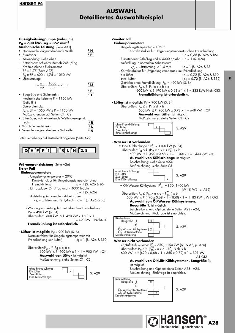
Flüssigkeitsringpumpe (vakuum)Pa = 600 kW, n2 = 357 min-1Mechanische Leistung (Seite A31)• Horizontale langsamdrehende Welle• Stirnräder- Anwendung: siehe oben- Betriebsart: schwerer Betrieb 24St./Tag- Kraftmaschine : Elektromotor SF = 1,75 (Seite A27)
Pa x SF = 600 x 1,75 = 1050 kW• Übersetzung:
• Baugröße und Stufenzahl :mechanische Leistung P = 1150 kW (Seite B1)überprüfen ob: Pa x SF = 1050 kW ≤ P = 1150 kWMaßzeichungen auf Seiten C1 - C2
• Stirnräder, schnelldrehende Welle ausragend:rechts
• Maschinenwelle links• Normale langsamdrehende Vollwelle
Bitte Getriebetyp auf Datenblatt angeben (Seite A29)
AUSWAHLDetailliertes Auswahlbeispiel
n1 1000n2 357
i = = = 2,80
Zweiter FallEinbauparameter:
. Umgebungstemperatur = 40°C :Korrekturfaktor für Umgebungstemperatur ohne Fremdkühlung
: a = 0,68 (S. A26 & B6). Einsatzdauer 24h/Tag und > 4000 h/Jahr : b = 1 (S. A26). Aufstellung in normalem Arbeitsraum
vA = Luftströmung: ≥ 1,4 m/s : c = 1 (S. A26 & B8). Korrekturfaktor für Umgebungstemperatur mit Fremdkühlung:
ein Lüfter : df = 0,72 (S. A26 & B10)zwei Lüfter : dff = 0,72 (S. A26 & B12)
- Getriebe ohne Fremdkühlung: Ptn = 490 kW (S. B4) Überprüfen: Pa ≤ ? Ptn x a x b x c 600 kW ≤ ? 490 kW x 0,68 x 1 x 1 = 333 kW: Nicht OK!
Fremdkühlung ist erforderlich.
- Lüfter ist möglich: Ptf = 900 kW (S. B4) Überprüfen: Pa ≤ ? Ptf x df x b 600 kW ≤ ? 900 kW x 0,72 x 1 = 648 kW : OK!
Auswahl von Lüfter ist möglich.Maßzeichnung: siehe Seiten C1 - C2.
- Wasser ist vorhanden• Eine Kühlschlange : P = 1100 kW (S. B4) Überprüfen: Pa ≤ ? (Ptn x a x c + P ) x b
600 kW ≤ ? (490 x 0,68 x 1 + 1100) x 1 = 1433 kW: OK!Auswahl von Kühlschlange ist möglich.Beschreibung: siehe Seite A23, Maßzeichnung: siehe Seite C5
• Öl/Wasser Kühlsysteme: P = 850, 1400 kW
(W1 & W2, p. A26) Überprüfen: Pa ≤ (Ptn x a x c + P ) x b
600 kW ≤ ? (490 x 0,68 x 1 + 850) x 1 = 1183 kW : W1 OK! Auswahl von Öl/Wasser Kühlsystemen,
Baugröße 1, ist möglich.Beschreibung und Option: siehe Seiten A23 - A24, Maßzeichnung: Rückfrage ist empfohlen.
- Wasser nicht vorhanden Öl/Lüft Kühlsysteme: P = 650, 1150 kW (A1 & A2, p. A26) Überprüfen: Pa ≤ ? (Ptn x a x c + P x df) x b
600 kW ≤ ? (490 x 0,68 x 1 + 650 x 0,72) x 1 = 801 kW : A1 OK!
Auswahl von Öl/Lüft Kühlsystemen, Baugröße 1, ist möglich.Beschreibung und Option: siehe Seiten A23 - A24, Maßzeichnung: Rückfrage ist empfohlen.
7 L8 N
6 R
5 1
4 F
9 2,8
3 P
2 H
1Q
2 H
3 P
4 F
5 1 - 6
R7 L
8 N - 9
2, 8
S. A29
S. A29ohne FremdkühlungEin Lüfter XZwei LüfterEine Kühlschlange
ohne FremdkühlungEin LüfterZwei LüfterEine Kühlschlange X
Kühlsysteme Baugröße 1 X 2 3 Öl/Wasser Kühlsysteme X Öl/Luft KühlsystemeDruckschmierung
+tc +
tc
+tw
+tw
S. A29
Wärmegrenzleistung (Seite A26)Erster Fall
Einbauparameter:. Umgebungstemperatur = 20°C : Korrekturfaktor für Umgebungstemperatur ohne Fremdkühlung : a = 1 (S. A26 & B6). Einsatzdauer 24h/Tag und > 4000 h/Jahr
: b = 1 (S. A26). Aufstellung in normalem Arbeitsraum vA = Luftströmung: ≥ 1,4 m/s : c = 1 (S. A26 & B8)
- Wärmegrenzleistung für Getriebe ohne Fremdkühlung: Ptn = 490 kW (p. B4)
Überprüfen: 600 kW ≤ ? 490 kW x 1 x 1 x 1 = 490 kW : NichtOK!
Fremdkühlung ist erforderlich.
- Lüfter ist möglich: Ptf = 900 kW (S. B4)Korrekturfaktor für Umgebungstemperatur mit Fremdkühlung (ein Lüfter) : df = 1 (S. A26 & B10)
Überprüfen:Pa ≤ ? Ptf x df x b 600 kW ≤ ? 900 kW x 1 x 1 = 900 kW : OK!
Auswahl von Lüfter ist möglich.Maßzeichnung: siehe Seiten C1 - C2.
S. A29ohne FremdkühlungEin Lüfter XZwei LüfterEine Kühlschlange
S. A29
Kühlsysteme Baugröße 1 X 2 3 Öl/Wasser Kühlsysteme Öl/Luft Kühlsysteme XDruckschmierung
+ta +
ta
D
ansen
A28
Pagina: 1
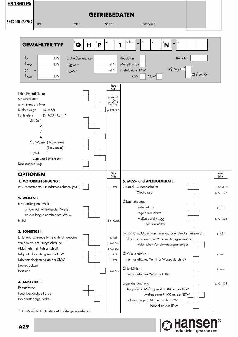
GETRIEBEDATEN97QX-00000532D A
Ref : Date : Name : Unterschrift :
1. MOTORBEFESTIGUNG :
IEC Motormantel : Fundamentrahmen (M10) p. A21
2. WELLEN :
eine verlängerte Welle
an der schnelldrehenden Welle
an der langsamdrehenden Welle
in Zoll Zoll Katal.
3. SONSTIGE :
Entlüftungsschraube für feuchte Umgebung p. A21
staubdichte Entlüftungsschraube p. A21 &C7
Ablaßhahn mit Rohranschluß p. A21 &C8
Labyrinthabdichtung an der LDW p. A21
Labyrinthabdichtung an der SDW p. A21
Duplex Bolzen
Heizstab p. A21 &C6
4. ANSTRICH :
Epoxidfarbe
Feuchtbeständige Farbe
Hochbeständige Farbe
* für Manifold Kühlsystem ist Rückfrage erforderlich
OPTIONEN SieheSeite
SieheSeite
keine Fremdkühlung -
Standardlüfterp. A21 &C1/C2
zwei Standardlüfterp. A21 &C1/C2
Kühlschlange (S. A23) p. A21 &C5
Kühlsystem (S. A23 - A24) *
Größe 1
2
3
4
Öl/Wasser (Flußwasser)
(Seewasser)
Öl/Luft
zentrales Kühlsystem
Druckschmierung
SieheSeite
5. MESS- und ANZEIGEGERÄTE :
Ölstand : Ölstandschalter p. A21 &C7
Ölschauglas p. A21 &C7
Ölbadtemperatur
fester Alarm p. A21
regelbarer Alarm
Meßapparat Pt100 p. A21 &C8
mit Transmittor
Für Kühlung, Ölumlaufschmierung oder Druckschmierung : p. A24
Filter : - mechanischer Verschmutzungsanzeiger
- elektrischer Verschmutzungsanzeiger
Öl-Wasserkühler : p. A24
thermostatisches Ventil für Wasserdurchfluß
Öl-Luftkühler : p. A24
thermostatisches Ventil für Lüfter
Lagerüberwachung p. A21 &C8
Temperatur: Meßapparat Pt100 an der LDW
Meßapparat Pt100 an der SDW
Schwingungen: Nippel an der LDW
Nippel an der LDW
A29
ansen
GEWÄHLTER TYP Q H P4
15 bis - 6 7
N - 9
CW
CW
1 2 3 5 8
Pa = kW Exakte Übersetzung = Reduktion
Pmot = kW nSDW = min-1 Multiplikation
SF = nLDW = min-1 Drehrichtung LDW :
Pnom = kW CW CCW
Anzahl
Pagina: 1
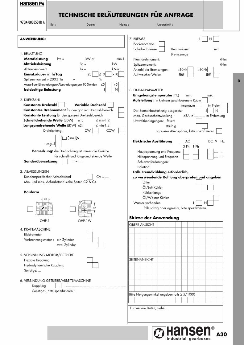
TECHNISCHE ERLÄUTERUNGEN FÜR ANFRAGE97QX-0000501D A
Ref : Datum : Name : Unterschrift :
ANWENDUNG:
1. BELASTUNG Motorleistung Pm = kW at min-1 Abtriebsleistung Pa = kW Abtriebsmoment Ta = kNm Einsatzdauer in h/Tag ≤3 ≤10 >10 Spitzenmoment > 200% Ta = % Anzahl der Einschaltungen/Abschaltungen pro 10 Stunden ≤5 >5 beidseitige Belastung J N
2. DREHZAHL Konstante Drehzahl Variable Drehzahl Konstantes Drehmoment für den ganzen Drehzahlbereich Konstante Leistung für den ganzen Drehzahlbereich Schnelldrehende Welle (SDW) n1: ≤ min-1 ≤ Langsamdrehende Welle (LDW) n2: ≤ min-1 ≤ Drehrichtung : CW CCW
Bemerkung: die Drehrichtung ist immer die Gleiche für schnell- und langsamdrehende Welle Sonderübersetzung i = ....
3. ABMESSUNGEN Kundenspezifischer Achsabstand CA = .... Min. und max. Achsabstand siehe Seiten C2 & C4
Bauform
4. KRAFTMASCHINE Elektromotor Verbrennungsmotor : ein Zylinder zwei Zylinder
5. VERBINDUNG MOTOR/GETRIEBE Flexible Kupplung Hydrodynamische Kupplung Sonstige: ...
6. VERBINDUNG GETRIEBE/ARBEITSMASCHINE Kupplung ............................................................ Sonstiges: bitte spezifizieren :
Skizze der AnwendungOBERE ANSICHT
SEITENANSICHT
Bitte Neigungswinkel angeben falls ≥ 5/1000
7. BREMSE J N Backenbremse Scheibenbremse Durchmesser: mm Bremszange Nenndrehmoment: kNm Spitzenmoment: kNm Anzahl der Bremsungen: ≤10/h ≥10/h Auf welcher Welle: SDW LDW
8. EINBAUPARAMETER Umgebungstemperatur (°C) min: max: Aufstellung : in kleinem geschlossenem Raum Innenraum im Freien Der Sonnenbestrahlung ausgesetzt J N Max. Geräuschentwicklung : dBA in ........... m Entfernung Umweltbedingungen: feucht staubig agressive Atmosphäre, bitte spezifizieren
Elektrische Ausführung AC DC V Hz 3 Ph 1 Ph Hauptspannung und Frequenz .... .... Hilfsspannung und Frequenz .... .... Schutzanforderungen: Isolation: Falls Fremdkühlung erforderlich, zu verwendende Kühlung überprüfen und angeben Lüfter Öl/Luft Kühler Kühlschlange Öl/Wasser Kühler Wasser vorhanden J N falls salzig oder agressiv, bitte spezifizieren
Für weitere Daten, siehe ...
CW
CW
ansen
CA
CA
QHP.1 QHP.1W
D
A30
Pagina: 1
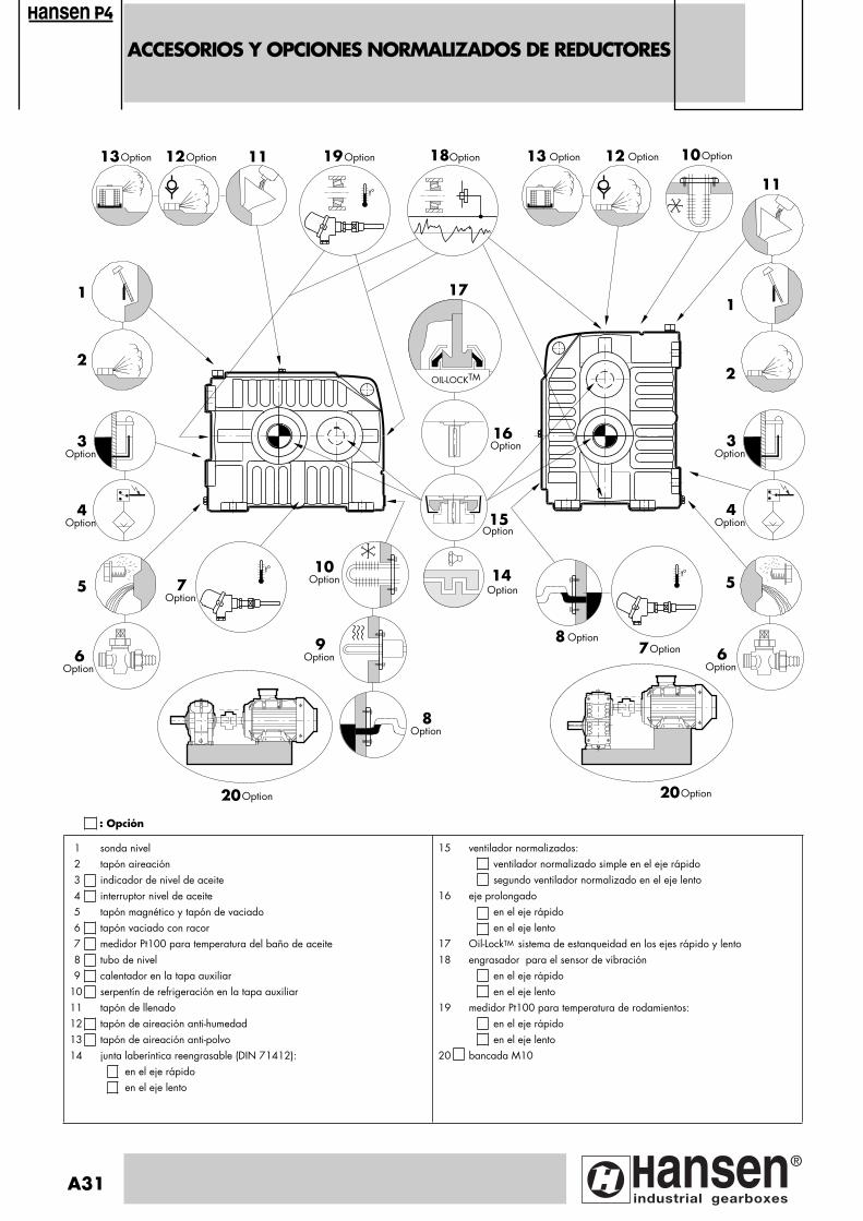
ACCESORIOS Y OPCIONES NORMALIZADOS DE REDUCTORES
ansen
1 sonda nivel2 tapón aireación3 indicador de nivel de aceite 4 interruptor nivel de aceite5 tapón magnético y tapón de vaciado6 tapón vaciado con racor7 medidor Pt100 para temperatura del baño de aceite8 tubo de nivel9 calentador en la tapa auxiliar
10 serpentín de refrigeración en la tapa auxiliar11 tapón de llenado12 tapón de aireación anti-humedad13 tapón de aireación anti-polvo14 junta laberíntica reengrasable (DIN 71412):
en el eje rápidoen el eje lento
15 ventilador normalizados:ventilador normalizado simple en el eje rápido segundo ventilador normalizado en el eje lento
16 eje prolongadoen el eje rápidoen el eje lento
17 Oil-LockTM sistema de estanqueidad en los ejes rápido y lento18 engrasador para el sensor de vibración
en el eje rápidoen el eje lento
19 medidor Pt100 para temperatura de rodamientos:en el eje rápidoen el eje lento
20 bancada M10
: Opción
A31
OIL-LOCKTM
t°
1
2
4Option
3Option
5
6Option
t°
7Option
8Option
10Option
8 Option7Option 6
Option
5
2
1
11
13 Option
15
16
18191112Option13Option
20Option 20Option
10Option
t°���
����
���
��
��
��
���
�
��
�
��
�����
�
�
�
�
�
����
��
�
�
14
12 Option
4Option
3Option
Option
Option Option
Option
9Option
Option
17
Pagina: 1
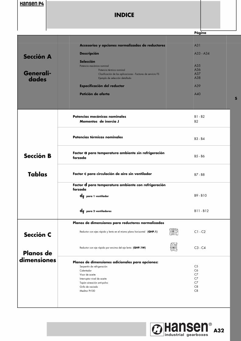
Página
Sección A
Generali-dades
Accesorios y opciones normalizados de reductores
Descripción
SelecciónPotencia mecánica nominal
Potencia térmica nominal
Clasificación de las aplicaciones - Factores de servicio FS
Ejemplo de selección detallado
Especificación del reductor
Petición de oferta
A31
A33 - A34
A35 A36A37A38
A39
A40
Potencias mecánicas nominalesMomentos de inercia J
B1 - B2B2
Potencias térmicas nominales B3 - B4
Sección BFactor a para temperatura ambiente sin refrigeración forzada B5 - B6
Tablas Factor c para circulación de aire sin ventilador B7 - B8
Factor d para temperatura ambiente con refrigeraciónforzada
df para 1 ventilador B9 - B10
df para 2 ventiladores B11 - B12
Sección C
Planos de dimensiones para reductores normalizados
Reductor con ejes rápido y lento en el mismo plano horizontal (QHP.1) C1 - C2
Planos deReductor con eje rápido por encima del eje lento (QHP.1W) C3 - C4
dimensiones
Planos de dimensiones adicionales para opciones: Serpentín de refrigeración
Calentador
Visor de aceite
Interruptor nivel de aceite
Tapón aireación anti-polvo
Grifo de vaciado
Meditor Pt100
C5C6C7C7C7C8C8
INDICE
ansen
S
A32
Pagina: 1

DESCRIPCION
Reductor
Código
Tipo1 : Serie Q : Hansen P42 : H : Eje lento horizontal3 : P : Ejes paralelos4 : Tamaño: C -> G5 : Número de etapas: 15 bis : W: Eje rápido por encima del eje lento
/ : Ejes rápido y lento en el mismo plano horizontal
Disposición de ejes 6 : Extensión eje rápido:
L : izquierdaR : derecha
7 : Extensión eje lento:L : izquierdaR : derecha
Nota: solamente la disposición de ejes LR o RL es posible
8 : Tipo de eje lento :N : eje macizo normal
Indice9 : Indice nominal
Elementos constitutivos
Engranajes helicoidalesDiseñados y calculados según las normas AGMA, ISO en vigor, y unalarga experiencia para alcanzar una capacidad de carga máxima, pérdidas mínimas y un funcionamiento silencioso.Las tablas de selección señalan las potencias mecánicas P expresadasen kW, que los reductores pueden transmitir con carga uniforme durante 10 horas/dia. Durante este período, 5 pares punta de hasta200% del valor nominal y duración máxima de 5 segundos por parpunta son admisibles.Las potencias mecánicas nominales señaladas en las tablas se refierenrespectivamente a velocidades de entrada de 1800, 1500, 1200,1000, 900 y 750 min -1.Son válidas asimismo para velocidades asíncronas hasta 3% inferioresa las velocidades de sincronismo de los motores. Para las potencias a velocidades intermedias es suficiente con inter-polar. El par considerado constante, calculado a 750 min -1 servirá debase para determinar la potencia en velocidades inferiores. Para velo-cidades de entrada superiores a 1800 min -1 rogamos consultar.Todos los engranajes se fabrican en aceros aleados, tratados por ce-mentación, templados y rectificados. El mismo proceso se aplica paratodos los ejes de entrada.
Ejes lentosLos ejes lentos están disponibles unicamente en ejecución maciza.
RodamientosRodamientos rodillos cónicos de capacidad elevada en todos los ejes.Calculados según normas AGMA, ISO y las especificaciones de losmás renombrados fabricantes.
CárteresFabricados en fundición perlítica gris en centros de mecanizado decontrol numérico (CNC).Diseñados para asegurar máxima resistencia y rigidez.
Diseñados para disipar el calor.Diseñados para reducir el nivel sonoro.
Sistemas
LubrificaciónLubrificantes: aceites minerales y sintéticos están permitidos.Los lubricantes deben siempre contener aditivos "EP" adecuados (vermanual de mantenimiento).El engrase por barboteo del baño de aceite es de serie.El carter constituye un baño de aceite voluminoso;Engrase a presión: se especifica en las tablas de selección.Accesorios en opción: ver página A31.
EstanqueidadEstática: utilización general de un producto de sellado
tapa de inspección: junta
Dinámica: eje rápido y eje lento: • sistema "Oil-Lock TM": - laberinto doble efecto
- sin mantenimiento- retorno al baño de aceite
• junta laberíntica reengrasable bajo demanda
RefrigeraciónEl calor generado por las pérdidas del reductor, puede disiparsepor:• refrigeración natural a través del carter• refrigeración mediante ventilador• serpentín de refrigeración• combinación de serpentín refrigeración y ventilador(es)• refrigerador agua-aceite o aire-aceite• sistema de refrigeración centralControl térmico: ver página A36.
Accesorios para la refrigeración
1. Ventilador estándarUn ventilador simple va montado sobre el eje rápido. Un segundoventilador se puede montar en el eje lento. El acceso libre de airepor el lado de aspiración debe estar garantizado.
2. Serpentín estándar de refrigeración por aguaLa potencia térmica suplementaria Ptc
+ y las dimensiones de las co-nexiones corresponden a un sistema de refrigeración como él indica-do a continuación:- Serpentín de refrigeración estándar fabricado a partir de una
aleación de cobre CuNi10Fe1Mn, según la norma DIN 17664 y que permite tanto la utilización de agua dulce como la de agua de mar (máxima presión de agua admisible = 8 bar).
- La diferencia entre la temperatura del baño de aceite y del agua de refrigeración es de 60°C.
- El caudal de agua varía entre 5 y 18 l/min: en los planos de dimensiones certificados se concretan estos datos.
- Planos de dimensiones en la página C5.
Nota: el serpentín de refrigeración puede quitarse sin desmontar elreductor.
3. Sistemas de refrigeración por aire y por aguaCuando la refrigeración mediante ventilador estándar no essuficiente o es poco adecuada para la aplicación, o bien, no secontempla un serpentín estándar mediante agua, puederecomendarse un sistema de refrigeración aire-aceite o agua-aceite.Para planos de dimensiones: sírvanse consultarnos.
3.1. Sistema estándar de refrigeración por aire-aceiteEste sistema se puede suministrar conectado al reductor o como unelemento separado (ver figura pag. A34).
3.2. Sistema estándar de refrigeración por agua-aceiteEste sistema se puede suministrar conectado al reductor o como unelemento separado (ver figura pag. A34).
3.3. Para la refrigeración mediante el nuevo diseño conjuntoManifold, con motor y bomba acoplados y aparatos de mediciónincorporados, sírvanse consultarnos.
1Q
2H
3P
4 51
5 bis - 6 7 8N - 9
ansen
A33
Pagina: 1
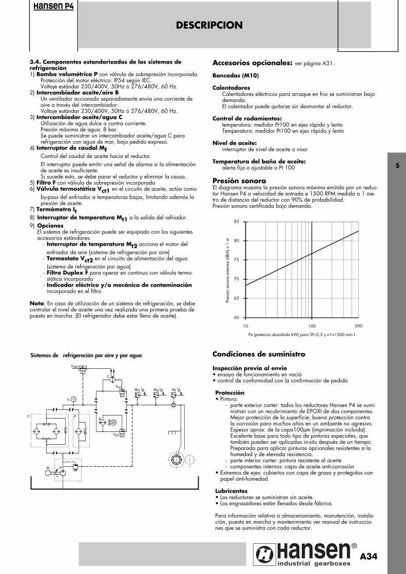
DESCRIPCION
3.4. Componentes estandarizados de los sistemas de refrigeración1) Bomba volumétrica P con válvula de sobrepresión incorporada.
Protección del motor eléctrico: IP54 según IEC.Voltaje estándar 230/400V, 50Hz ó 276/480V, 60 Hz.
2) Intercambiador aceite/aire BUn ventilador accionado separadamente envía una corriente de aire a través del intercambiador.Voltaje estándar 230/400V, 50Hz ó 276/480V, 60 Hz.
3) Intercambiador aceite/agua CUtilización de agua dulce a contra corriente.Presión máxima de agua: 8 bar.Se puede suministrar un intercambiador aceite/agua C para refrigeración con agua de mar, bajo pedido expreso.
4) Interruptor de caudal MfControl del caudal de aceite hacia el reductor.El interruptor puede emitir una señal de alarma si la alimentación de aceite es insuficiente.Si sucede esto, se debe parar el reductor y eliminar la causa.
5) Filtro F con válvula de sobrepresión incorporada6) Válvula termostática Vct1 en el circuito de aceite, actúa como
by-pass del enfriador a temperaturas bajas, limitando además la presión de aceite.
7) Termómetro It8) Interruptor de temperatura Mt1 a la salida del refriador.9) Opciones
El sistema de refrigeración puede ser equipado con los siguientesaccesorios estándares:
- Interruptor de temperatura Mt2 acciona el motor del enfriador de aire (sistema de refrigeración por aire)
- Termostato Vct2 en el circuito de alimentación del agua(sistema de refrigeración por agua)
- Filtro Duplex F para operar en continuo con válvula termo-stática incorporada
- Indicador eléctrico y/o mecánico de contaminación incorporado en el filtro
Nota: En caso de utilización de un sistema de refrigeración, se debecontrolar el nivel de aceite una vez realizada una primera prueba depuesta en marcha. (El refrigerador debe estar lleno de aceite).
ansen
F
M P
F
It t°
B
t°
Vct1
C
Vct2
Mt1 Mf
M
Vct1 t°
Mt2
t°
Sistemas de refrigeración por aire y por agua
Accesorios opcionales: ver página A31.
Bancadas (M10)
CalentadoresCalentadores eléctricos para arraque en frio se suministran bajo demanda.El calentador puede quitarse sin desmontar el reductor.
Control de rodamientos:temperatura: medidor Pt100 en ejes rápido y lentoTemperatura: medidor Pt100 en ejes rápido y lento
Nivel de aceite: interruptor de nivel de aceite o visor
Temperatura del baño de aceite:alerta fija o ajustable o Pt 100
Presión sonoraEl diagrama muestra la presión sonora máxima emitida por un reduc-tor Hansen P4 a velocidad de entrada e 1500 RPM medida a 1 me-tro de distancia del reductor con 90% de probabilidad.Presión sonora certificada bajo demanda.
Condiciones de suministro
Inspección previa al envio• ensayo de funcionamiento en vació• control de conformidad con la confirmación de pedido
Protección• Pintura:
- parte exterior carter: todos los reductores Hansen P4 se sumi-nistran con un recubrimiento de EPOXI de dos componentes.Mejor protección de la superficie; buena protección contra la corrosión para muchos años en un ambiente no agresivo. Espesor aprox. de la capa100µm (imprimación incluida). Excelente base para todo tipo de pinturas especiales, que
también pueden ser aplicadas in-situ después de un tiempo.Preparada para aplicar pinturas opcionales resistentes a lahumedad y de elevada resistencia.
- parte interior carter: pintura resistente al aceite- componentes internos: capa de aceite anti-corrosión
• Extremos de ejes: cubiertos con capa de grasa y protegidos con papel anti-humedad. Lubricantes• Los reductores se suministran sin aceite.• Los engrasadores están llenados desde fábrica.
Para información relativa a almacenamiento, manutención, instala-ción, puesta en marcha y mantenimiento ver manual de instruccio-nes que se suministra con cada reductor.
10 100
60
65
70
75
80
85
Pa (potencia absorbida kW) para SF≤2,5 y n1=1500 min-1
Pres
ión
sono
ra m
áxim
a (d
BA) a
1 m
500
S
A34
Pagina: 1
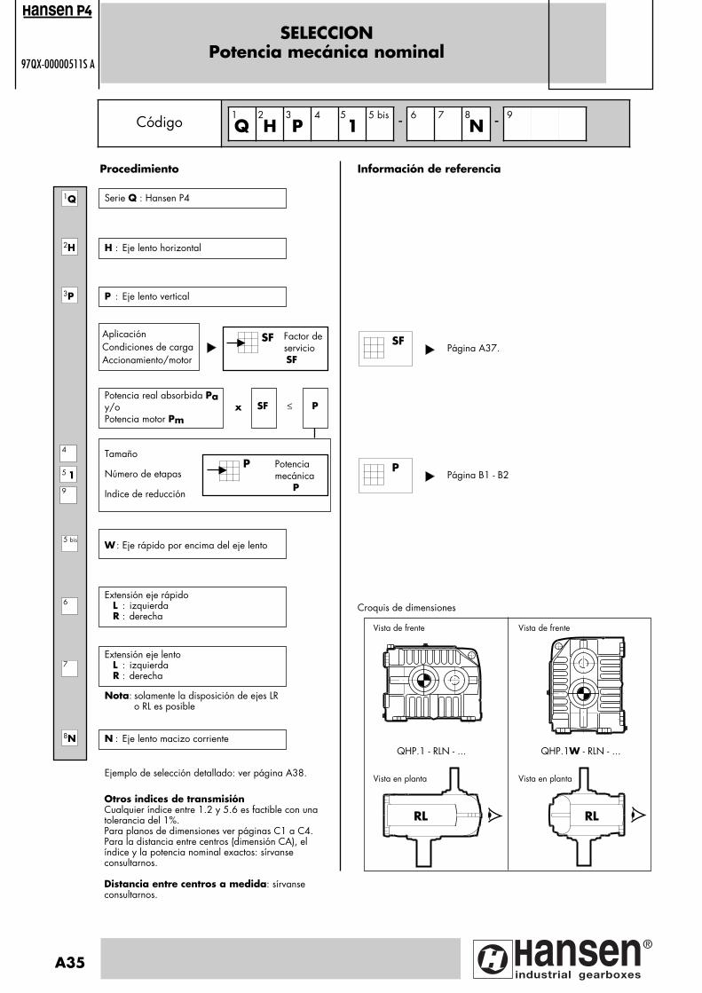
SELECCIONPotencia mecánica nominal
97QX-00000511S A
Factor deservicio SF
H : Eje lento horizontal
Información de referencia
AplicaciónCondiciones de cargaAccionamiento/motor
Tamaño
Número de etapas
Indice de reducción
Potencia mecánica P
P
Potencia real absorbida Pay/oPotencia motor Pm
SF P x ≤
Extensión eje rápido L : izquierda
R : derecha
Extensión eje lento L : izquierda
R : derecha
Página A37.
Croquis de dimensiones
Código Q H P4
15 bis - 6 7
N - 9
2H
3P
5 19
4
7
8N
6
SF
Procedimiento
Serie Q : Hansen P41Q
1
5 bis
A35
2 3 5 8
P : Eje lento vertical
W : Eje rápido por encima del eje lento
Nota: solamente la disposición de ejes LRo RL es posible
N : Eje lento macizo corriente
Ejemplo de selección detallado: ver página A38.
Vista de frente Vista de frente
QHP.1 - RLN - ... QHP.1W - RLN - ...
RL RL
Vista en planta Vista en planta
ansen
Otros indices de transmisiónCualquier índice entre 1.2 y 5.6 es factible con unatolerancia del 1%. Para planos de dimensiones ver páginas C1 a C4. Para la distancia entre centros (dimensión CA), elíndice y la potencia nominal exactos: sírvanseconsultarnos.
Distancia entre centros a medida: sírvanseconsultarnos.
SF
Página B1 - B2P
Pagina: 1
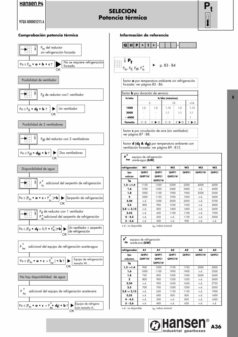
SELECIONPotencia térmica
97QX-00000521S A
Ptn del reductorsin refrigeración forzada
OK
Comprobación potencia térmica
Pa ≤ Ptn • a • b • c ?
Posibilidad de ventilador
No se requiere refrigeraciónforzada
Ptf de reductor con1 ventilador
Pa ≤ Ptf • df • b ?
Posibilidad de 2 ventiladores
Un ventilador
Ptff del reductor con 2 ventiladores
Pa ≤ Ptff • dff • b ?
Disponibilidad de agua
Dos ventiladores
P adicional del serpentín de refrigeración
Pa ≤ (Ptn • a • c + P )•b Serpentín de refrigeración
Pa ≤ (Ptn • a • c + P ) • b ? Equipo de refrigeracióntamaño W...
factor b por duración de servicioh/año h/dia (máximo)
3 10 >16
1000 1,2 1,3 1,15 1,2 1,15
2000 - - 1,1 1,1 1,1
≥ 4000 - - - - 1
Tamaño C - D E G C - D E G C G
refrigerador W1 W1 W2 W2 W3 W3
tipo
reductor
iN
QHPE1
QHPF1W
QHPF1
QHPG1
QHPG1W
QHPF1
QHPG1W
QHPG1 QHPG1W QHPG1
1,2 ->1,4 1150 1350 2200 2200 4200 4200
1,6 1250 1450 2400 2400 n.d. 4500
1,8 1000 1100 1900 1900 3500 3500
2 1000 1150 1950 1950 n.d. 3600
2,24 n.d. 1200 2050 2050 n.d. 3700
2,5 800 900 1550 1550 n.d. 2800
2,8 -> 3,15 n.d. 850 1400 1400 n.d. 2600
3,55 n.d. 650 1100 1100 n.d. 1950
4 - 4,5 n.d. 650 n.d. 1150 n.d. 2000
5 - 5,6 n.d. 500 n.d. 900 n.d. n.d.
n.d.: no disponible iN: índice nominal
Información de referencia
Pa ≤ (Ptn • a • c + P • df) • b ?Equipo de refrigera-ción tamaño A..
No hay disponibilidad de agua
P adicional del equipo de refrigeración aceite-aire
P adicional del equipo de refrigeración aceite-agua+tw
+tw
+ta
+ta
OK
OK
OK
OK
OK
+tc
+
tc
Q H P • 1 • - -
Pt
factor a por temperatura ambiente sin refrigeraciónforzada: ver página B5 - B6.
factor c por circulación de aire (sin ventilador):ver página B7 - B8.
factor d (df & dff) por temperatura ambiente conventilación forzada: ver página B9 - B12.
Ptf de reductor con 1 ventilador
P adicional del serpentín de refrigeración+tc
Pa ≤ (Ptf • df + 0,9 • P )•b Un ventilador + serpentínde refrigeración
OK
ansen
Pt
Ptn, Ptf, Ptff, P+tc
S
P equipos de refrigeración aceite-agua (kW)
+
tw
+tc
refrigerador A1 A1 A2 A2 A3 A3
tipo
reductore
iN
QHPE1
QHPF1W
QHPF1
QHPG1
QHPG1W
QHPF1
QHPG1W
QHPG1 QHPG1W QHPG1
1,2 ->1,4 900 1000 1750 1750 3000 3000
1,6 1000 1100 1900 1900 n.d. 3200
1,8 750 850 1500 1500 2600 2600
2 800 900 1550 1550 n.d. 2600
2,24 n.d. 950 1650 1650 n.d. 2750
2,5 700 700 1200 1200 n.d. 2050
2,8 -> 3,15 n.d. 650 1150 1150 n.d. 1900
3,55 n.d. 600 850 850 n.d. 1400
4 - 4,5 n.d. 500 n.d. 850 n.d. 1450
5 - 5,6 n.d. 400 n.d. 650 n.d. n.d.
n.d.: no disponible iN: índice nominal
P equipos de refrigeración aceite-aire (kW)
+
ta
p. B3 - B4
A36
Pagina: 1
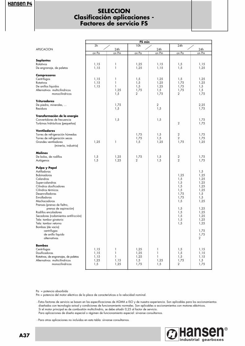
SELECCIONClasificación aplicaciones -
Factores de servicio FS
FS min3h 10h 24h
APLICACION 24h 24h 24hon Pa on Pm on Pa on Pm on Pa on Pm
SoplantesRotativos 1,15 1 1,25 1,15 1,5 1,15De engranaje, de paletas 1,15 1 1,25 1,15 1,5 1,25
CompresoresCentrífugos 1,15 1 1,5 1,25 1,5 1,25Rotativos 1,15 1 1,5 1,25 1,75 1,25De anillos líquidos 1,15 1 1,5 1,25 1,75 1,5Alternativos multicilíndricos 1,25 1,75 1,5 1,75 1,5 monocilíndricos 1,5 2 1,75 2 1,75 TrituradoresDe piedra, minerales, ... 1,75 2 2,25Residuos 1,5 1,5 1,75
Transformación de la energíaConvertidores de frecuencia 1,5 1,5 1,75Turbinas hidráulicas (pequeñas) 2 1,75
VentiladoresTorres de refrigeración húmedas 1,75 1,5 2 1,75Torres de refrigeración secas 1,75 1,5 2 1,75Grandes ventiladores 1,25 1 1,5 1,25 1,75 1,25 (minería, industria)
MolinosDe bolas, de rodillos 1,5 1,25 1,75 1,5 2 1,75Autógenos 1,5 1,25 2 1,5 2 1,75
Pulpa y PapelAstilladoras 1,5Bobinadoras 1,25 1,25Calandras 1,5 1,25Super-calandras 1,5 1,25Cilindros dosificadores 1,5 1,25Cilindros térmicos 1,5 1,25Desenrolladoras 1,75 1,5Enrolladoras 1,75 1,5Machacadoras 1,5 1,25Prensas (prensa de fieltro, prensa de aspiración) 1,5 1,25Rodillos encoladores 1,5 1,25Secadores (rodamientos antifricción) 1,5 1,25Tela: tambor giratorio 1,5 1,25Tela: tambor retorno 1,5 1,25Bombas (de vacío) centrífugas 1,75 de anillo líquido 1,75 alternativas 2
BombasCentrifugas 1,15 1 1,25 1 1,5 1,15Dosificadoras 1,15 1 1,25 1 1,5 1,15Rotativas, de engranajes, de paletas 1,15 1 1,25 1 1,5 1,15Alternativos multicilíndricos 1,25 1,15 1,5 1,25 1,75 1,5 monocilíndricos 1,5 1,25 1,75 1,5 2 1,75
A37
ansen
Pa = potencia absorbidaPm = potencia del motor eléctrico de la placa de características a la velocidad nominal.
- Estos factores de servicio se basan en las especificaciones de AGMA e ISO y de nuestra experiencia. Son aplicables para los accionamientos diseñados con tecnología actual y condiciones de funcionamiento normales. Son aplicables a accionamientos con motores eléctricos. Si el motor principal es de combustión multicilindrio, se debe añadir 0,25 al factor de servicio. Para aplicaciones de diseño especial o régimen de funcionamiento especial: sírvanse consultarnos.
- Para otras aplicaciones no incluidas en esta tabla: sírvanse consultarnos.
Pagina: 1

Bomba de anillo líquido (de vacío) Pa = 600 kW, n2 = 357 min-1Potencia mecánica (página A35)• Eje lento horizontal• Se requieren ejes paralelos- aplicación: ver arriba- condiciones de carga: servicio pesado 24h/24h- accionamiento: motor eléctrico SF = 1,75 (página A37)
Pa x SF = 600 x 1,75 = 1050 kW• Indice de reducción:
• Tamaño y número de etapas: Potencia mecánica P = 1150 kW (página B1) comprobar: Pa x SF = 1050 kW ≤ P = 1150 kW para dimensiones ver página B27• Extensión eje rápido: derecha• Eje de la máquina hacia la izquierda• Eje lento macizo corriente
Rogamos indiquen el tipo de unidad en la hoja de especi-ficación (página A39)
SELECCIÓN Ejemplo de selección detallado
n1 1000n2 357
i = = = 2,80
Segundo casoCondiciones de funcionamiento
. Temperatura ambiente = 40° C:Factor de correción sin refrigeración forzada
: a = 0,68 (p. A36 & B6). Horas de funcionamiento 24h/dia en > 4000 h/año
: b = 1 (p. A36). Instalación interior, area de trabajo normal vA = flujo de aire: ≥ 1,4m/s
: c = 1 (p. A36 & B8)Factor de correción con refrigeración forzada, , un ventilador
: df = 0,72 (p. A36 & B10)Factor de correción con refrigeración forzada, dos ventiladores
: dff = 0,72 (p. A36 & B12)- Unidad sin refrigeración forzada: Ptn = 490 kW (p. B4) Comprobación:Pa ≤ ? Ptn x a x b x c
600 kW ≤ ? 490 kW x 0,68 x 1 x 1= 333 kW : No OK! Se requiere refrigeración extra
- Ventilador posible: Ptf = 900 kW (p. B4) Comprobación:Pa ≤ ? Ptf x df x b
600 kW ≤ ? 900 kW x 0,72 x 1 = 648 kW : OK! Solución con ventilador es posible. Dimensiones ver página C1 - C2
- Disponibilidad de agua • Serpentín: P = 1100 kW (p. B4) Comprobación: Pa ≤ ? (Ptn x a x c + P ) x b
600 kW ≤ ? (490 x 0,68 x 1 + 1100) x 1 = 1433 kW : OK! Solución con serpentín es posible. Descripción ver página A33, dimensiones ver página C5
• Refrigerador aceite-agua: P = 850, 1400 kW (W1 & W4, p. A36)
Comprobación: Pa ≤ (Ptn x a x c + P ) x b 600 kW ≤ ? (490 x 0,68 x 1+ 850) x 1= 1183 kW : W1 OK! Solución con refrigerador aceite-agua
tamaño 1 es posible. Descripción y opciones: p. A33 - A34, Plano de dimensiones : sírvanse consultarnos.
- No hay disponibilidad de agua Refrigerador aceite - aire: P = 650, 1150 kW (A1 & A2, p. A36) Comprobación:
Pa ≤ ? (Ptn x a x c + P x df) x b600 kW ≤ ? (490 x 0,68 x 1 + 650 x 0,72) x 1 = 801 kW :
A1 OK!
Solución con refrigerador aceite-aire tamaño 1 es posible.Descripción y opciones: p. A33 - A34, Plano de dimensiones : sírvanse consultarnos.
7 L8 N
6 R
5 1
4 F
9 2,8
3 P
2 H
1Q
2 H
3 P
4 F
5 1 - 6
R7 L
8 N - 9
2, 8
p. A39
p. A39sin refrigeración extraventilador Xdos ventiladoresserpentín
sin refrigeración extraventiladordos ventiladoresserpentín X
Sistema de refrigeración tamaño 1 X 2 3aceite - agua Xaceite - airelubrificación a presión
+tc +
tc
+tw
+tw
p. A39
Potencia térmica (ver página A36)
Primer casoCondiciones de funcionamiento
. Temperatura ambiente = 20° C: Factor de correción sin refrigeración forzada
: a = 1 (p. A36 & B6). Horas de funcionamiento 24h/dia en > 4000 h/año
: b = 1 (p. A36). Instalación interior, area de trabajo normal vA = flujo de aire: ≥ 1,4m/s : c = 1 (p. A36 & B8)
- Unidad sin refrigeración forzada : Ptn = 490 kW (p. B4)Comprobación: 600 kW ≤ ? 490 kW x 1 x 1 x 1
= 490 kW : No OK! Se requiere refrigeración extra.
- Ventilador posible: Ptf = 900 kW (p. B4) Factor de correción con refrigeración forzada, un ventilador : df = 1 (p. A36 & B10)
Comprobación: Pa ≤ ? Ptf x df x b 600 kW ≤ ? 900 kW x 1 x 1 = 900 kW : OK!
Solución con ventilador es posible. Dimensiones ver página C1 - C2
p. A39sin refrigeración extra Xventiladordos ventiladoresserpentín
+ta
+ta
Sistema de refrigeración tamaño 1 X 2 3aceite - agua Xaceite - airelubrificación a presión
p. A39
S
ansen
A38
Pagina: 1

ESPECIFICACION DEL REDUCTOR97QX-00000532S A
Ref : Fecha : Nombre : Firma :
1. MONTAJE DEL MOTOR :
brida IEC : bancada M10 p. A31
2. EJES :
eje prolongado en el eje rápido
eje prolongado en el eje lento
pulgadas inch catal.
3. OTROS :
tapón de aireación anti-humedad p. A31
tapón anti-polvo p. A31 &C7
tapón vaciado con racor p. A31 &C8
junta laberintica reengrasable en el eje lento p. A31
junta laberintica reengrasable en el eje rápido p. A31
tornillos galvanizados
calentador p. A31 &C6
4. PINTURA :
pintura epoxy
pintura resistente a la humedad
pintura de elevada resistencia
* para conjunto de refrigeración Manifold rogamos: sírvanse consultarnos.
OPCIONES INFORMA-CION
INFORMA-CION
sin refrigeración extra -
ventilador normalizadop. A31 &C1/C2
segundo ventilador normalizadop. A31 &C1/C2
serpentin de refrigeración (p. A33) p. A31 &C5
equipo de refrigeración (p. A33 - 34) *
tamaño 1
2
3
4
aceite-agua (agua dulce)
(agua del mar)
aceite-aire
sistema de refrigeración central
lubricación a presión
INFORMA-CION
5. INSTRUMENTACIÓN :
nivel de aceite: interruptor p. A31 &C7
visor de aceite p. A31 &C7
Temperatura baño de aceite:
alarma fija p. A31
alarma ajustable
medidor Pt100 p. A31 &C8
con transmisor
Si hay sistema de refrigeración o de lubrificación por p. A34
circulación o a presión:
filtro de contaminación: indicador mecánico
indicador eléctrico
Si hay refrigerador aceite-agua p. A34
válvula termostática del caudal de agua
Si hay refrigerador aceite-aire p. A34
interruptor termico del ventilador
Control de rodamientos p. A31 &C8
temperatura: medidor Pt100 en el eje lento
medidor Pt100 en el eje rápido
vibración: leva en el eje rápido
leva en el eje rápido
A39
ansen
TIPO SELECCIONADO Q H P4
15 bis - 6 7
N - 9
CW
CW
1 2 3 5 8
Pa = kW Indice de reducciónexacto = reductor
Pmot = kW neje rapido = min-1 multiplicator
SF = neje lento = min-1 Sentido de rotación del eje lento:
Pnom = kW CW CCW
cantidad
horario anti-horario
Pagina: 1

PETICION DE OFERTA97QX-0000501S A
Ref : Fecha : Nombre : Firma :
APLICACIÓN:
1. CARGA Potencia motor Pm = kW à min-1
Potencia absorbida Pa = kW Par absorbido Ta = kNm Funcionamiento en h/dia ≤3 ≤10 >10 Par punta superior a 200% Ta = % Número de arranques/paradas por 10 horas ≤5 >5 Carga bidireccional Y N
2. VELOCIDAD Velocidad constante Velocidad variable Par constante para toda la gama de velocidad Potencia constante para toda la gama de velocidad Eje rápido (ER) n1: ≤ min-1 ≤ Eje lento (EL) n2: ≤ min-1 ≤ sentido de giro: CW = horario CCW = anti-hor.
Nota: el sentido de giro siempre queda igual para ejes rápido y lento Indice especial i = ....
3. DIMENSIONES Distancia entre centros a medida CA = .... Distancia entre centros min. & max.: ver pág. C2 & C4
Posición de montaje
4. MOTOR Motor eléctrico Motor de combustión interna: un cilindro multi-cilindros
5. CONEXION MOTOR/REDUCTOR Acoplamiento fléxible Acoplamiento hidrodinámico Otros: ...
6. CONEXION REDUCTOR/MÁQUINA ACCIONADA acoplamiento .................................................. otros: a especificar
ESQUEMA DE APLICACIÓNVISTA EN PLANTA
VISTA LATERAL
Rogamos indicar ángulo de inclinación si ≥ 5/1000
7. FRENO Y N Freno de tambor Freno de disco Dia: mm Pinzas de presión Par nominal: kNm Pico de par kNm Frecuencia de frenados: ≤10/h ≥10/h en que eje: ER EL
8. PARÁMETROS DE FUNCIONAMIENTO Temperatura ambiente (°C) min: max: Situación: espacio cerrado reducido al interior al exterior
A pleno sol Y N Nivel de ruido max.: dBA à ............. m Ambiente: húmedo polvoriento agresivo: a especificar
Instalación eléctrica AC DC V Hz 3 Ph 1 Ph Alimentación principal .... .... Alimentación auxiliar .... .... Protección requerida: Aislamiento: Caso de necesitar refrigeración suplementaria indicar lo que se requiere: Ventilador Refrigeración aceite/aire Serpentín de refrigeración Refrigeración aceite/agua Disponibilidad de agua Y N si agresiva, especificar
Para otros datos ver:
CW
CW
ansen
CA
CA
QHP.1 QHP.1W
S
A40
Pagina: 1
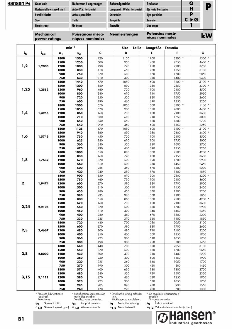
min-1 Size - Taille - Baugröße - TamañoiN iex n1 n2 C D E F G
1800 1500 720 1150 1700 3300 * 5500 *1500 1250 600 950 1400 2750 4600 *
1,2 1,2000 1200 1000 490 770 1150 2200 37001000 830 410 650 960 1850 3100
900 750 370 580 870 1700 2850750 630 310 490 730 1400 2400
1800 1440 670 1050 1600 3100 * 5100 *1500 1200 560 890 1350 2550 4300 *
1,25 1,2553 1200 960 460 720 1100 2100 35001000 800 380 610 910 1750 2950
900 720 350 550 820 1600 2650750 600 290 460 690 1350 2250
1800 1300 670 1050 1600 3100 * 5100 *1500 1050 570 900 1350 2600 4400 *
1,4 1,4255 1200 860 460 730 1100 2100 36001000 710 380 610 910 1750 3000
900 640 350 550 820 1600 2700750 540 290 460 690 1350 2250
1800 1125 670 1050 1600 3100 * 5100 *1500 940 560 890 1350 2600 4400 *
1,6 1,5745 1200 750 450 720 1100 2100 35001000 625 380 610 900 1750 3000
900 560 340 550 820 1600 2700750 470 290 460 690 1350 2250
1800 1000 550 880 1300 2500 4200 *1500 830 460 740 1100 2150 3600
1,8 1,7632 1200 670 370 590 890 1700 29001000 560 310 500 750 1450 2450
900 500 285 450 670 1300 2200750 420 240 380 570 1100 1850
1800 900 550 870 1300 2500 4200 *1500 750 460 730 1100 2100 3600
2 1,9474 1200 600 370 590 880 1700 29001000 500 310 500 740 1450 2450
900 450 280 450 670 1300 2200750 380 235 380 560 1100 1850
1800 800 550 860 1300 2500 4200 *1500 670 460 730 1100 2100 3600
2,24 2,2105 1200 540 370 590 880 1700 29001000 450 310 490 740 1450 2450
900 400 280 440 670 1300 2200750 330 235 370 560 1100 1850
1800 720 440 700 1050 2050 31001500 600 370 590 880 1700 2650
2,5 2,4667 1200 480 300 480 710 1400 22001000 400 250 400 600 1150 1900
900 360 225 360 540 1050 1700750 300 190 300 450 880 1450
1800 640 440 700 1050 2050 31001500 540 370 590 880 1700 2650
2,8 2,8000 1200 430 300 470 710 1400 22001000 360 250 400 600 1150 1900
900 320 225 360 540 1050 1700750 270 190 300 450 880 1450
1800 570 400 630 930 1800 27501500 480 340 530 780 1500 2350
3,15 3,1111 1200 380 270 420 630 1250 19501000 320 225 360 530 1050 1700
900 285 205 320 480 930 1550750 240 170 270 400 780 1300
Gear unitHorizontal low speed shaft
Parallel shafts
Size
Single stage
Réducteur à engrenagesArbre P.V. horizontal
Arbres parallèles
Taille
Un étage
ZahnradgetriebeLangsamdr. Welle: horizontal
Stirnräder
Baugröße
Einstufig
ReductorEje lento horizontal
Ejes paralelos
Tamaño
Una etapa
PH
C G1
Q
Mechanicalpower ratings
Puissances méca-niques nominales
Nennleistungen Potencias mecá-nicas nominales
P
kW
* Se requiere lubricación apresiónSirvanse consultar.
* Lubrification sous pressionest indispensable.Veuillez nous consulter.
* Druckschmierung erforder-lich.Rückfrage zu empfehlen.
* Pressure lubrication isrequired. Refer to us
ansen
iN Rapport nominaln1,2 Vitesse nominale
iN Nennübersetzungn1,2 Nenndrehzahl
iN Nominal ration1,2 Nominal speed (rpm)
B1
iN Índice nominaln1,2 Velocidades nominales (r.p.m.)
Pagina: 1

ansen Gear unitHorizontal low speed shaft
Parallel shafts
Size
Single stage
Réducteur à engrenagesArbre P.V. horizontal
Arbres parallèles
Taille
Un étage
ZahnradgetriebeLangsamdr. Welle: horizontal
Stirnräder
Baugröße
Einstufig
ReductorEje lento horizontal
Ejes paralelos
Tamaño
Una etapa
PH
C G1
Q
Mechanicalpower ratings
Puissances méca-niques nominales
Nennleistungen Potencias mecá-nicas nominales
P
kW
iN Rapport nominaln1,2 Vitesse nominale
iN Nennübersetzungn1,2 Nenndrehzahl
iN Nominal ration1,2 Nominal speed (rpm)
min-1 Size - Taille - Baugröße - TamañoiN iex n1 n2 C D E F G
1800 510 380 560 960 1650 22501500 420 330 480 830 1450 1950
3,55 3,5263 1200 340 275 400 690 1200 16001000 280 235 350 580 1050 1400
900 255 215 315 520 940 1250750 210 180 270 430 800 1100
1800 450 380 560 940 1650 22501500 375 330 480 780 1450 1950
4 3,8947 1200 300 275 400 620 1200 16001000 250 235 340 520 1050 1400
900 225 215 300 470 940 1250750 190 180 255 390 790 1100
1800 400 380 540 830 1650 22501500 330 320 450 690 1400 1950
4,5 4,4211 1200 265 255 360 550 1100 16001000 220 215 295 460 930 1400
900 200 190 270 410 840 1250750 165 160 225 340 700 1050
1800 360 275 400 740 1300 18001500 300 230 340 620 1150 1550
5 4,9333 1200 240 185 275 490 910 13001000 200 155 230 410 760 1100
900 180 140 205 370 690 1000750 150 120 175 310 580 860
1800 320 280 410 650 1300 18001500 270 235 340 540 1100 1550
5,6 5,6000 1200 215 190 275 430 880 13001000 180 155 230 360 730 1100
900 160 140 210 330 660 980750 135 120 175 270 550 820
Size - Taille - Baugröße - TamañoiN C D E F G
1,2 0,115 0,26 0,52 1,55 3,8
1,25 0,1 0,22 0,45 1,35 3,3
1,4 0,11 0,245 0,49 1,45 3,6
1,6 0,115 0,25 0,5 1,5 3,7
1,8 0,065 0,15 0,3 0,89 2,15
2 0,07 0,155 0,32 0,94 2,3
2,24 0,085 0,185 0,37 1,1 2,65
2,5 0,045 0,1 0,205 0,59 1,45
2,8 0,05 0,115 0,235 0,68 1,7
3,15 0,04 0,095 0,195 0,56 1,4
3,55 0,02 0,07 0,19 0,47 1,1
4 0,025 0,07 0,205 0,51 1,15
4,5 0,04 0,085 0,24 0,6 1,35
5 0,02 0,055 0,145 0,36 0,83
5,6 0,03 0,065 0,17 0,42 0,96
Moments of inertia J related to the HSS
Moments d'inertie J rapportés à l'arbre G.V.
MassenträgheitsmomenteJ beziehen sich auf die SDW
Momentos de inercia J relativos al eje rápido kgm2 J
QHP.1.P (kW)J (kgm2)
B2
iN Índice nominaln1,2 Velocidades nominales (r.p.m.)
Pagina: 1
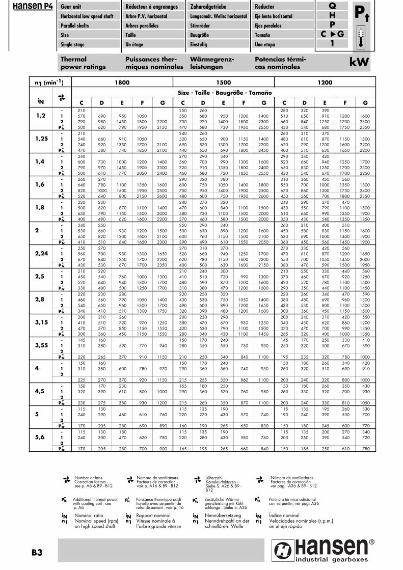
Gear unitHorizontal low speed shaft
Parallel shafts
Size
Single stage
Réducteur à engrenagesArbre P.V. horizontal
Arbres parallèles
Taille
Un étage
ZahnradgetriebeLangsamdr. Welle: horizontal
Stirnräder
Baugröße
Einstufig
ReductorEje lento horizontal
Ejes paralelos
Tamaño
Una etapa
PH
C G1
Q
Thermalpower ratings
Puissances ther-miques nominales
Wärmegrenz-leistungen
Potencias térmi-cas nominales
Pt
kW
n1 (min-1) 1800 1500 1200
Size - Taille - Baugröße - TamañoiN C D E F G C D E F G C D E F G
- 210 250 260 280 320 3901,2 1 570 690 950 1050 550 680 950 1200 1400 510 650 910 1200 1600
2 790 980 1450 1800 2200 730 920 1400 1800 2300 660 840 1250 1700 2300500 620 790 1950 2150 470 580 730 1950 2550 430 540 680 1750 2350
- 210 240 260 260 310 3701,25 1 540 660 910 1050 520 650 900 1150 1400 480 610 870 1150 1500
2 740 920 1350 1700 2100 690 870 1300 1700 2200 620 790 1200 1600 2200470 580 740 1850 2100 440 550 690 1800 2450 400 510 630 1650 2200
- 240 270 290 340 290 340 4201,4 1 600 730 1000 1200 1400 560 700 990 1300 1600 520 660 940 1250 1700
2 790 970 1450 1900 2300 720 910 1350 1800 2400 650 830 1250 1700 2300500 610 770 2050 2400 460 580 720 1850 2550 430 540 670 1700 2250
- 260 270 290 320 380 310 360 450 5601,6 1 640 780 1100 1350 1600 600 750 1050 1400 1800 550 700 1000 1350 1800
2 820 1000 1500 1950 2500 750 950 1400 1900 2500 670 860 1300 1750 2400520 640 800 2150 2600 480 600 750 1950 2600 450 560 700 1800 2350
- 220 230 240 270 320 240 290 370 4701,8 1 500 620 870 1100 1400 470 600 840 1100 1500 430 550 790 1100 1500
2 630 790 1150 1500 2000 580 730 1100 1500 2000 510 660 990 1350 1900400 490 620 1600 2200 370 460 580 1500 2000 350 430 540 1350 1850
- 240 250 250 290 340 260 310 400 5102 1 530 660 930 1200 1500 500 630 890 1200 1600 450 580 830 1150 1600
2 650 820 1200 1600 2100 600 760 1150 1500 2100 530 690 1000 1400 1900410 510 640 1650 2300 390 490 610 1550 2050 360 450 560 1450 1900
- 250 270 270 310 370 270 330 420 5602,24 1 560 700 980 1300 1650 520 660 940 1250 1700 470 610 870 1200 1650
2 670 840 1250 1700 2200 620 780 1150 1600 2200 550 700 1050 1450 2000430 530 670 1700 2350 400 500 630 1600 2150 380 470 590 1500 1950
- 210 220 210 240 300 210 250 330 440 5602,5 1 450 540 760 1000 1300 410 510 720 990 1300 370 460 670 920 1250
2 520 640 940 1300 1700 480 590 870 1200 1600 420 520 780 1100 1500330 400 500 1250 1700 310 380 470 1200 1600 290 350 440 1100 1450
- 220 230 280 220 250 320 220 260 340 470 5902,8 1 460 560 790 1050 1400 430 530 750 1050 1400 380 480 690 960 1300
2 540 650 960 1300 1700 490 600 890 1200 1650 430 530 800 1100 1500340 410 510 1300 1750 320 390 480 1200 1600 300 360 450 1150 1500
- 200 210 260 200 230 290 200 240 310 420 5503,15 1 410 510 720 970 1250 380 470 670 930 1250 340 430 620 860 1200
2 470 570 850 1150 1550 420 530 790 1100 1500 370 470 700 990 1350300 360 450 1150 1550 280 340 430 1100 1450 265 320 400 1000 1350
- 145 160 150 170 240 145 170 250 330 4103,55 1 310 380 590 770 940 280 350 550 730 930 250 320 500 670 890
2220 265 370 910 1150 210 250 340 840 1100 195 235 320 780 1000
- 150 160 150 170 240 150 180 260 340 4204 1 310 380 600 780 970 290 360 560 740 950 260 320 510 690 910
2225 270 370 920 1150 215 255 350 860 1100 200 240 320 800 1000
- 150 170 230 155 180 250 150 180 260 350 4304,5 1 320 390 610 800 1000 290 360 570 760 980 260 330 520 700 930
2230 275 380 930 1200 215 260 350 870 1100 200 240 330 810 1050
- 115 130 115 135 190 115 135 195 260 3305 1 240 290 460 610 760 220 270 430 570 740 190 240 390 530 700
2170 205 280 690 890 160 190 265 650 830 150 180 245 600 770
- 115 130 180 115 135 190 115 135 200 270 3405,6 1 240 300 470 620 780 220 280 430 580 760 200 250 390 540 720
2170 205 280 700 900 165 195 265 660 840 150 185 250 610 780
P+tc
iN Índice nominaln1 Velocidades nominales (r.p.m.)
en el eje rápido
iN Rapport nominaln1 Vitesse nominale à
l'arbre grande vitesse
iN Nennübersetzungn1 Nenndrehzahl an der
schnelldreh. Welle
iN Nominal ration1 Nominal speed (rpm)
on high speed shaft
Potencia térmica adicional con serpentín, ver pag. A36
Puissance thermique addi-tionelle avec serpentin de refroidissement - voir p. 16
Zusätzliche Wärme-grenzleistung mit Kühl-schlange - Siehe S. A26
Additional thermal power with cooling coil - see p. A6
P+tc P+
tc P+tc P+
tc
Número de ventiladores.Factores de corrección ver pag. A36 & B9 - B12
Nombre de ventilateurs.Facteurs de correction -
voir p. A16 & B9 - B12
Lüfterzahl.Korrekturfaktoren -
Siehe S. A26 & B9 -B12
Number of fans.Correction factors -
see p. A6 & B9 - B12
P+tc
P+tc
P+tc
P+tc
P+tc
P+tc
P+tc
P+tc
P+tc
P+tc
P+tc
P+tc
P+tc
ansen
B3
Pagina: 1
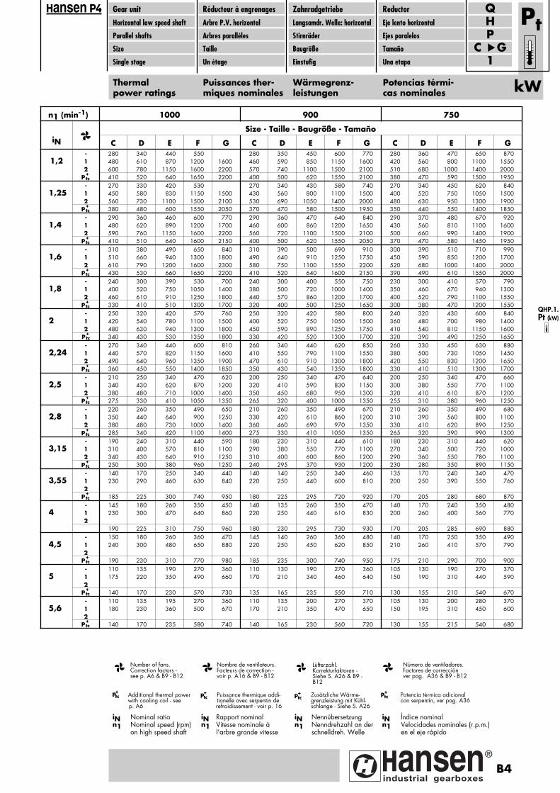
Gear unitHorizontal low speed shaft
Parallel shafts
Size
Single stage
Réducteur à engrenagesArbre P.V. horizontal
Arbres parallèles
Taille
Un étage
ZahnradgetriebeLangsamdr. Welle: horizontal
Stirnräder
Baugröße
Einstufig
ReductorEje lento horizontal
Ejes paralelos
Tamaño
Una etapa
PH
C G1
Q
Thermalpower ratings
Puissances ther-miques nominales
Wärmegrenz-leistungen
Potencias térmi-cas nominales
Pt
kW
n1 (min-1) 1000 900 750
Size - Taille - Baugröße - TamañoiN C D E F G C D E F G C D E F G
- 280 340 440 550 280 350 450 600 770 280 360 470 650 8701,2 1 480 610 870 1200 1600 460 590 850 1150 1600 420 560 800 1100 1550
2 600 780 1150 1600 2200 570 740 1100 1500 2100 510 680 1000 1400 2000410 520 640 1650 2200 400 500 620 1550 2100 380 470 590 1500 1950
- 270 330 420 530 270 340 430 580 740 270 340 450 620 8401,25 1 450 580 830 1150 1500 430 560 800 1100 1500 400 520 750 1050 1500
2 560 730 1100 1500 2100 530 690 1050 1400 2000 480 630 950 1300 1900380 480 600 1550 2050 370 470 580 1500 1950 350 440 550 1400 1850
- 290 360 460 600 770 290 360 470 640 840 290 370 480 670 9201,4 1 480 620 890 1200 1700 460 600 860 1200 1650 430 560 810 1100 1600
2 590 760 1150 1600 2200 560 720 1100 1500 2100 500 660 990 1400 1900410 510 640 1600 2150 400 500 620 1550 2050 370 470 580 1450 1950
- 310 380 490 650 840 310 390 500 690 910 300 390 510 710 9901,6 1 510 660 940 1300 1800 490 640 910 1250 1750 450 590 850 1200 1700
2 610 790 1200 1600 2300 580 750 1100 1550 2200 520 680 1000 1400 2000430 530 660 1650 2200 410 520 640 1600 2150 390 490 610 1550 2000
- 240 300 390 530 700 240 300 400 550 750 230 300 410 570 7901,8 1 400 520 750 1050 1400 380 500 720 1000 1400 350 460 670 940 1300
2 460 610 910 1250 1800 440 570 860 1200 1700 400 520 790 1100 1550330 410 510 1300 1700 320 400 500 1250 1650 300 380 470 1200 1550
- 250 320 420 570 760 250 320 420 580 800 240 320 430 600 8402 1 420 540 780 1100 1500 400 520 750 1050 1500 360 480 700 980 1400
2 480 630 940 1300 1800 450 590 890 1250 1750 410 540 810 1150 1600340 430 530 1350 1800 330 420 520 1300 1700 320 390 490 1250 1650
- 270 340 440 600 810 260 340 440 620 850 260 330 450 630 8802,24 1 440 570 820 1150 1600 410 550 790 1100 1550 380 500 730 1050 1450
2 490 640 960 1350 1900 470 610 910 1300 1800 420 550 830 1200 1650360 450 550 1400 1850 350 430 540 1350 1800 330 410 510 1300 1700
- 210 250 340 470 620 200 250 340 470 640 200 250 340 470 6602,5 1 340 430 620 870 1200 320 410 590 830 1150 300 380 550 770 1100
2 380 480 710 1000 1400 350 450 680 950 1300 320 410 610 870 1200275 330 410 1050 1350 265 320 400 1000 1350 255 310 380 960 1250
- 220 260 350 490 650 210 260 350 490 670 210 260 350 490 6802,8 1 350 440 640 900 1250 330 420 610 860 1200 310 390 560 800 1100
2 380 480 730 1000 1400 360 460 690 970 1350 330 410 620 890 1250285 340 420 1100 1400 275 330 410 1050 1350 265 320 390 990 1300
- 190 240 310 440 590 180 230 310 440 610 180 230 310 440 6203,15 1 310 400 570 810 1100 290 380 550 770 1100 270 340 500 720 1000
2 340 430 640 910 1250 310 400 600 860 1200 290 360 550 780 1100250 300 380 960 1250 240 295 370 930 1200 230 280 350 890 1150
- 140 170 250 340 440 140 140 250 340 460 135 170 240 340 4703,55 1 230 290 460 630 840 220 250 440 600 810 200 250 390 550 760
2185 225 300 740 950 180 225 295 720 920 170 205 280 680 870
- 145 180 260 350 450 140 135 260 350 470 140 170 240 350 4804 1 230 300 470 640 860 220 250 440 610 830 200 260 400 560 770
2190 225 310 750 960 180 230 295 730 930 170 205 285 690 880
- 150 180 260 360 470 145 140 260 360 480 140 170 250 350 4904,5 1 240 300 480 650 880 220 250 450 620 850 210 260 410 570 790
2190 230 310 770 980 185 235 300 740 950 175 210 290 700 900
- 110 135 190 270 360 110 130 190 270 360 105 130 190 270 3705 1 175 220 350 490 660 170 210 340 460 640 150 190 310 440 590
2140 170 230 570 730 135 165 235 550 710 130 155 210 540 670
- 110 135 195 270 360 110 135 200 270 370 105 130 200 280 3705,6 1 180 230 360 500 670 170 210 350 470 650 150 195 310 450 600
2140 170 235 580 740 140 165 230 560 720 130 155 215 540 680
P+tc
P+tc
P+tc
P+tc
P+tc
P+tc
P+tc
P+tc
P+tc
P+tc
P+tc
P+tc
P+tc
P+tc
ansen
QHP.1.Pt (kW)
iN Índice nominaln1 Velocidades nominales (r.p.m.)
en el eje rápido
iN Rapport nominaln1 Vitesse nominale à
l'arbre grande vitesse
iN Nennübersetzungn1 Nenndrehzahl an der
schnelldreh. Welle
iN Nominal ration1 Nominal speed (rpm)
on high speed shaft
Potencia térmica adicional con serpentín, ver pag. A36
Puissance thermique addi-tionelle avec serpentin de refroidissement - voir p. 16
Zusätzliche Wärme-grenzleistung mit Kühl-schlange - Siehe S. A26
Additional thermal power with cooling coil - see p. A6
P+tc P+
tc P+tc P+
tc
Número de ventiladores.Factores de corrección ver pag. A36 & B9 - B12
Nombre de ventilateurs.Facteurs de correction -
voir p. A16 & B9 - B12
Lüfterzahl.Korrekturfaktoren -
Siehe S. A26 & B9 -B12
Number of fans.Correction factors -
see p. A6 & B9 - B12
B4
Pagina: 1
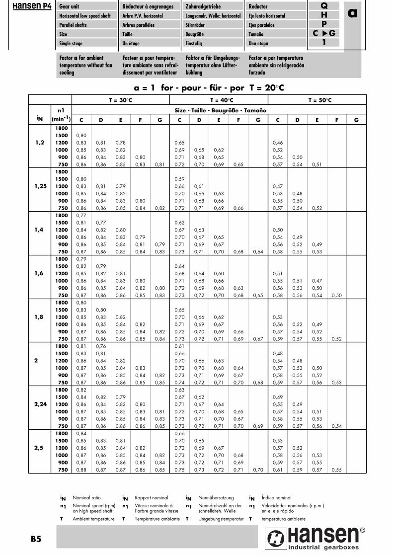
Gear unitHorizontal low speed shaft
Parallel shafts
Size
Single stage
Réducteur à engrenagesArbre P.V. horizontal
Arbres parallèles
Taille
Un étage
ZahnradgetriebeLangsamdr. Welle: horizontal
Stirnräder
Baugröße
Einstufig
ReductorEje lento horizontal
Ejes paralelos
Tamaño
Una etapa
PH
C G1
Q
Factor a for ambienttemperature without fancooling
Facteur a pour tempéra-ture ambiante sans refroi-dissement par ventilateur
Faktor a für Umgebungs-temperatur ohne Lüfter-kühlung
Factor a por temperaturaambiente sin refrigeraciónforzada
a
T = 30°C T = 40°C T = 50°C
n1 Size - Taille - Baugröße - TamañoiN (min-1) C D E F G C D E F G C D E F G
18001500 0,80
1,2 1200 0,83 0,81 0,78 0,65 0,461000 0,85 0,83 0,82 0,69 0,65 0,62 0,52
900 0,86 0,84 0,83 0,80 0,71 0,68 0,65 0,54 0,50750 0,86 0,86 0,85 0,83 0,81 0,72 0,70 0,69 0,65 0,57 0,54 0,51
18001500 0,80 0,59
1,25 1200 0,83 0,81 0,79 0,66 0,61 0,471000 0,85 0,84 0,82 0,70 0,66 0,63 0,53 0,48
900 0,86 0,84 0,83 0,80 0,71 0,68 0,66 0,55 0,50750 0,86 0,86 0,85 0,84 0,82 0,72 0,71 0,69 0,66 0,57 0,54 0,52
1800 0,771500 0,81 0,77 0,62
1,4 1200 0,84 0,82 0,80 0,67 0,63 0,501000 0,86 0,84 0,83 0,79 0,70 0,67 0,65 0,54 0,49900 0,86 0,85 0,84 0,81 0,79 0,71 0,69 0,67 0,56 0,52 0,49750 0,87 0,86 0,85 0,84 0,83 0,73 0,71 0,70 0,68 0,64 0,58 0,55 0,53
1800 0,791500 0,82 0,79 0,64
1,6 1200 0,85 0,82 0,81 0,68 0,64 0,60 0,511000 0,86 0,84 0,83 0,80 0,71 0,68 0,66 0,55 0,51 0,47900 0,86 0,85 0,84 0,82 0,80 0,72 0,69 0,68 0,63 0,56 0,53 0,50750 0,87 0,86 0,86 0,85 0,83 0,73 0,72 0,70 0,68 0,65 0,58 0,56 0,54 0,50
1800 0,801500 0,83 0,80 0,65
1,8 1200 0,85 0,83 0,82 0,70 0,66 0,62 0,531000 0,86 0,85 0,84 0,82 0,71 0,69 0,67 0,56 0,52 0,49900 0,87 0,86 0,85 0,84 0,82 0,72 0,70 0,69 0,66 0,57 0,54 0,52750 0,87 0,86 0,86 0,85 0,84 0,73 0,72 0,71 0,69 0,67 0,59 0,57 0,55 0,52
1800 0,81 0,76 0,611500 0,83 0,81 0,66 0,48
2 1200 0,86 0,84 0,82 0,70 0,66 0,63 0,54 0,481000 0,87 0,85 0,84 0,83 0,72 0,70 0,68 0,64 0,57 0,53 0,50900 0,87 0,86 0,85 0,84 0,82 0,73 0,71 0,69 0,67 0,58 0,55 0,52750 0,87 0,86 0,86 0,85 0,85 0,74 0,72 0,71 0,70 0,68 0,59 0,57 0,56 0,53
1800 0,82 0,631500 0,84 0,82 0,79 0,67 0,62 0,49
2,24 1200 0,86 0,84 0,83 0,80 0,71 0,67 0,64 0,55 0,491000 0,87 0,85 0,85 0,83 0,81 0,72 0,70 0,68 0,65 0,57 0,54 0,51900 0,87 0,86 0,85 0,84 0,83 0,73 0,71 0,70 0,67 0,58 0,55 0,53750 0,87 0,86 0,86 0,86 0,85 0,73 0,72 0,71 0,70 0,69 0,59 0,57 0,56 0,54
1800 0,84 0,661500 0,85 0,83 0,81 0,70 0,65 0,53
2,5 1200 0,86 0,85 0,84 0,82 0,72 0,69 0,67 0,57 0,521000 0,87 0,86 0,85 0,84 0,82 0,73 0,72 0,70 0,68 0,58 0,56 0,53900 0,87 0,86 0,86 0,85 0,84 0,73 0,72 0,71 0,69 0,59 0,57 0,55750 0,88 0,87 0,87 0,86 0,85 0,75 0,73 0,72 0,71 0,70 0,61 0,59 0,57 0,55
iN Índice nominal
n1 Velocidades nominales (r.p.m.) en el eje rápido
T temperatura ambiente
iN Rapport nominal
n1 Vitesse nominale à l'arbre grande vitesse
T Température ambiante
iN Nennübersetzung
n1 Nenndrehzahl an der schnelldreh. Welle
T Umgebungstemperatur
iN Nominal ratio
n1 Nominal speed (rpm) on high speed shaft
T Ambient temperature
a = 1 for - pour - für - por T = 20°C
ansen
B5
Pagina: 1
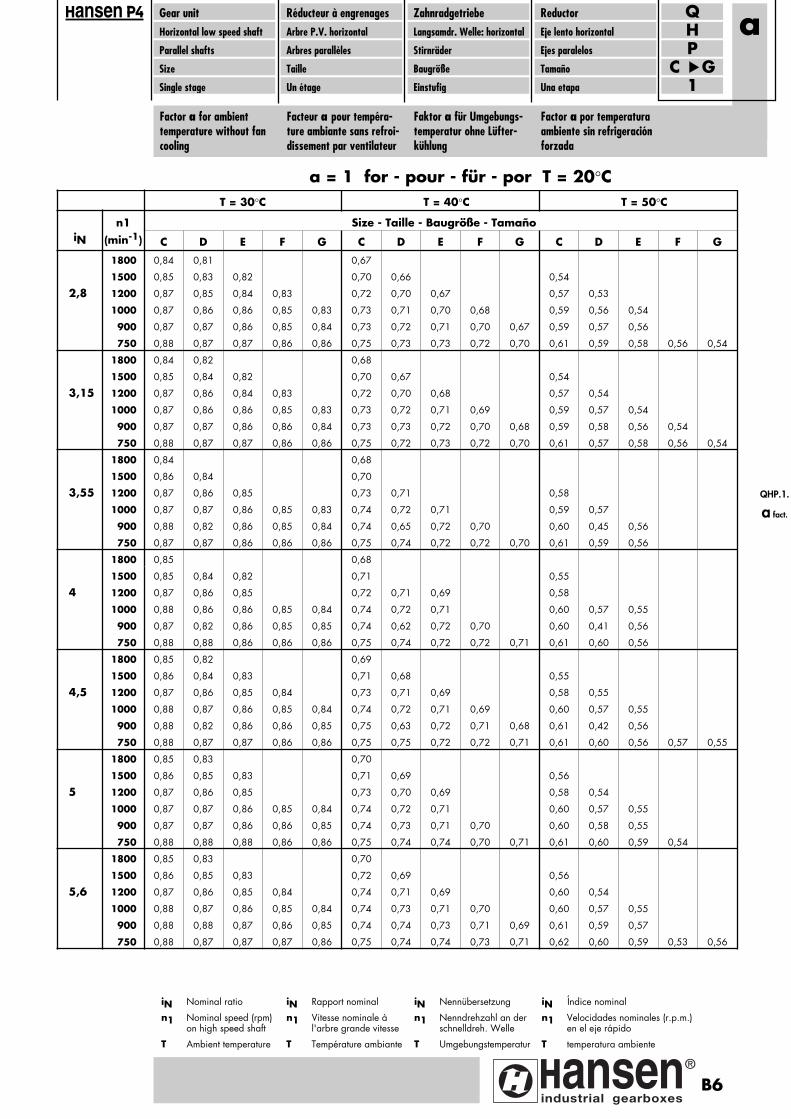
Gear unitHorizontal low speed shaft
Parallel shafts
Size
Single stage
Réducteur à engrenagesArbre P.V. horizontal
Arbres parallèles
Taille
Un étage
ZahnradgetriebeLangsamdr. Welle: horizontal
Stirnräder
Baugröße
Einstufig
ReductorEje lento horizontal
Ejes paralelos
Tamaño
Una etapa
PH
C G1
Q
Factor a for ambienttemperature without fancooling
Facteur a pour tempéra-ture ambiante sans refroi-dissement par ventilateur
Faktor a für Umgebungs-temperatur ohne Lüfter-kühlung
Factor a por temperaturaambiente sin refrigeraciónforzada
a
T = 30°C T = 40°C T = 50°C
n1 Size - Taille - Baugröße - TamañoiN (min-1) C D E F G C D E F G C D E F G
1800 0,84 0,81 0,67
1500 0,85 0,83 0,82 0,70 0,66 0,54
2,8 1200 0,87 0,85 0,84 0,83 0,72 0,70 0,67 0,57 0,53
1000 0,87 0,86 0,86 0,85 0,83 0,73 0,71 0,70 0,68 0,59 0,56 0,54
900 0,87 0,87 0,86 0,85 0,84 0,73 0,72 0,71 0,70 0,67 0,59 0,57 0,56
750 0,88 0,87 0,87 0,86 0,86 0,75 0,73 0,73 0,72 0,70 0,61 0,59 0,58 0,56 0,54
1800 0,84 0,82 0,68
1500 0,85 0,84 0,82 0,70 0,67 0,54
3,15 1200 0,87 0,86 0,84 0,83 0,72 0,70 0,68 0,57 0,54
1000 0,87 0,86 0,86 0,85 0,83 0,73 0,72 0,71 0,69 0,59 0,57 0,54
900 0,87 0,87 0,86 0,86 0,84 0,73 0,73 0,72 0,70 0,68 0,59 0,58 0,56 0,54
750 0,88 0,87 0,87 0,86 0,86 0,75 0,72 0,73 0,72 0,70 0,61 0,57 0,58 0,56 0,54
1800 0,84 0,68
1500 0,86 0,84 0,70
3,55 1200 0,87 0,86 0,85 0,73 0,71 0,58
1000 0,87 0,87 0,86 0,85 0,83 0,74 0,72 0,71 0,59 0,57
900 0,88 0,82 0,86 0,85 0,84 0,74 0,65 0,72 0,70 0,60 0,45 0,56
750 0,87 0,87 0,86 0,86 0,86 0,75 0,74 0,72 0,72 0,70 0,61 0,59 0,56
1800 0,85 0,68
1500 0,85 0,84 0,82 0,71 0,55
4 1200 0,87 0,86 0,85 0,72 0,71 0,69 0,58
1000 0,88 0,86 0,86 0,85 0,84 0,74 0,72 0,71 0,60 0,57 0,55
900 0,87 0,82 0,86 0,85 0,85 0,74 0,62 0,72 0,70 0,60 0,41 0,56
750 0,88 0,88 0,86 0,86 0,86 0,75 0,74 0,72 0,72 0,71 0,61 0,60 0,56
1800 0,85 0,82 0,69
1500 0,86 0,84 0,83 0,71 0,68 0,55
4,5 1200 0,87 0,86 0,85 0,84 0,73 0,71 0,69 0,58 0,55
1000 0,88 0,87 0,86 0,85 0,84 0,74 0,72 0,71 0,69 0,60 0,57 0,55
900 0,88 0,82 0,86 0,86 0,85 0,75 0,63 0,72 0,71 0,68 0,61 0,42 0,56
750 0,88 0,87 0,87 0,86 0,86 0,75 0,75 0,72 0,72 0,71 0,61 0,60 0,56 0,57 0,55
1800 0,85 0,83 0,70
1500 0,86 0,85 0,83 0,71 0,69 0,56
5 1200 0,87 0,86 0,85 0,73 0,70 0,69 0,58 0,54
1000 0,87 0,87 0,86 0,85 0,84 0,74 0,72 0,71 0,60 0,57 0,55
900 0,87 0,87 0,86 0,86 0,85 0,74 0,73 0,71 0,70 0,60 0,58 0,55
750 0,88 0,88 0,88 0,86 0,86 0,75 0,74 0,74 0,70 0,71 0,61 0,60 0,59 0,54
1800 0,85 0,83 0,70
1500 0,86 0,85 0,83 0,72 0,69 0,56
5,6 1200 0,87 0,86 0,85 0,84 0,74 0,71 0,69 0,60 0,54
1000 0,88 0,87 0,86 0,85 0,84 0,74 0,73 0,71 0,70 0,60 0,57 0,55
900 0,88 0,88 0,87 0,86 0,85 0,74 0,74 0,73 0,71 0,69 0,61 0,59 0,57
750 0,88 0,87 0,87 0,87 0,86 0,75 0,74 0,74 0,73 0,71 0,62 0,60 0,59 0,53 0,56
iN Índice nominal
n1 Velocidades nominales (r.p.m.) en el eje rápido
T temperatura ambiente
iN Rapport nominal
n1 Vitesse nominale à l'arbre grande vitesse
T Température ambiante
iN Nennübersetzung
n1 Nenndrehzahl an der schnelldreh. Welle
T Umgebungstemperatur
iN Nominal ratio
n1 Nominal speed (rpm) on high speed shaft
T Ambient temperature
a = 1 for - pour - für - por T = 20°C
ansen
QHP.1.
a fact.
B6
Pagina: 1

Gear unitHorizontal low speed shaft
Parallel shafts
Size
Single stage
Réducteur à engrenagesArbre P.V. horizontal
Arbres parallèles
Taille
Un étage
ZahnradgetriebeLangsamdr. Welle: horizontal
Stirnräder
Baugröße
Einstufig
ReductorEje lento horizontal
Ejes paralelos
Tamaño
Una etapa
PH
C G1
Q
Factor c for air circulation(without fan)
Facteur c pour circulationd'air (sans ventilateur)
Faktor c für Luftzirkula-tion (ohne Lüfter)
Factor c por circulación deaire (sin ventilador)
c
vA ≥ 0,5 m/s vA ≥ 3,0 m/s
n1 Size - Taille - Baugröße - TamañoiN (min-1) C D E F G C D E F G
1800 1,561500 1,44 1,54
1,2 1200 0,63 1,37 1,42 1,481000 0,69 0,65 0,59 1,34 1,37 1,40 1,47
900 0,71 0,68 0,64 1,32 1,35 1,37 1,41 1,47750 0,73 0,71 0,69 0,65 1,31 1,32 1,34 1,34 1,39
1800 1,541500 1,43 1,52
1,25 1200 0,65 1,36 1,40 1,461000 0,70 0,65 0,61 1,33 1,36 1,39 1,45
900 0,72 0,68 0,65 1,32 1,34 1,36 1,40 1,45750 0,73 0,72 0,70 0,66 1,31 1,32 1,33 1,34 1,38
1800 1,491500 0,58 1,41 1,48 1,58
1,4 1200 0,67 0,61 1,34 1,39 1,431000 0,71 0,67 0,64 1,32 1,35 1,37 1,42 1,47
900 0,72 0,70 0,67 1,31 1,33 1,35 1,37 1,42750 0,74 0,72 0,71 0,68 0,65 1,31 1,32 1,33 1,33 1,36
1800 1,46 1,591500 0,61 1,39 1,46 1,54
1,6 1200 0,68 0,63 1,34 1,38 1,42 1,501000 0,72 0,69 0,65 1,32 1,34 1,37 1,39 1,45
900 0,73 0,70 0,68 0,63 1,31 1,33 1,35 1,36 1,40750 0,74 0,72 0,71 0,69 0,66 1,30 1,31 1,32 1,32 1,35
1800 1,43 1,541500 0,64 1,36 1,42 1,50
1,8 1200 0,70 0,65 1,33 1,36 1,39 1,461000 0,72 0,69 0,67 1,31 1,33 1,35 1,37 1,42
900 0,73 0,71 0,69 0,66 1,31 1,32 1,34 1,34 1,38750 0,74 0,73 0,72 0,71 0,69 1,30 1,30 1,31 1,32 1,33
1800 1,42 1,521500 0,65 1,35 1,42 1,48
2 1200 0,71 0,67 0,61 1,33 1,35 1,38 1,431000 0,73 0,70 0,68 1,31 1,33 1,35 1,36 1,40
900 0,73 0,72 0,70 0,67 1,31 1,32 1,33 1,34 1,36750 0,74 0,73 0,73 0,72 0,69 1,30 1,30 1,31 1,32 1,32
1800 0,59 1,40 1,491500 0,66 1,35 1,41 1,46
2,24 1200 0,71 0,67 0,63 1,32 1,35 1,38 1,411000 0,73 0,71 0,69 0,64 1,31 1,32 1,34 1,35 1,39
900 0,74 0,72 0,71 0,68 0,65 1,30 1,32 1,33 1,33 1,35750 0,74 0,74 0,73 0,72 0,70 1,30 1,30 1,31 1,31 1,32
1800 0,64 1,36 1,451500 0,68 0,63 1,34 1,38 1,42
2,5 1200 0,72 0,69 0,66 1,32 1,34 1,36 1,38 1,451000 0,74 0,72 0,70 0,68 1,31 1,32 1,33 1,34 1,37
900 0,74 0,73 0,72 0,71 1,31 1,31 1,32 1,33 1,34750 0,75 0,74 0,74 0,73 0,72 1,30 1,30 1,30 1,31 1,32
c = 1 for - pour - für - por vA ≥ 1,4 m/s
ansen
vA = Flujo de aire:
≥ 0,5 m/s: instalación interior, local pequeño
≥ 1,4 m/s: instalación interior area de trabajo normal
≥ 3,0 m/s: instalación exterior, protegido cont. radi. solar
iN Índice nominal
n1 Velocidades nominales (r.p.m.) en el eje rápido
vA = courant d'air:
≥ 0,5 m/s: installation dans un petit local fermé
≥ 1,4 m/s: installation dans un atelier normal
≥ 3,0 m/s: installation en plein air, protégé du soleil
iN Rapport nominal
n1 Vitesse nominale à l'arbre grande vitesse
vA = Luftströmung:
≥ 0,5 m/s: Aufstellung in kleinem, geschlossenem Raum
≥ 1,4 m/s: Aufstellung in normalem Arbeitsraum
≥ 3,0 m/s: Aufstellung im Freien, Sonnenschutz
iN Nennübersetzung
n1 Nenndrehzahl an der schnelldreh. Welle
vA = air flow:
≥ 0,5 m/s: mounting indoors - small enclosure
≥ 1,4 m/s: mounting indoors - normal working area
≥ 3,0 m/s: mounting outdoors - protected against sun
iN Nominal ratio
n1 Nominal speed (rpm) on high speed shaft
B7
Pagina: 1
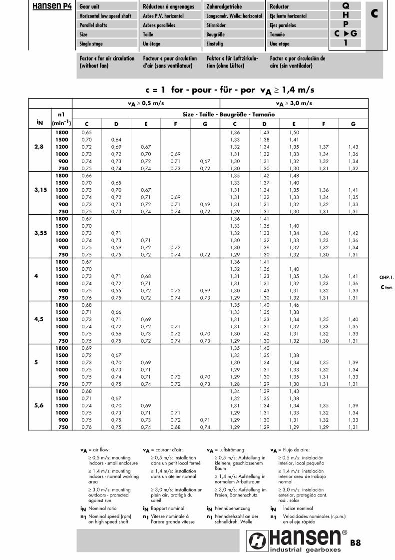
Gear unitHorizontal low speed shaft
Parallel shafts
Size
Single stage
Réducteur à engrenagesArbre P.V. horizontal
Arbres parallèles
Taille
Un étage
ZahnradgetriebeLangsamdr. Welle: horizontal
Stirnräder
Baugröße
Einstufig
ReductorEje lento horizontal
Ejes paralelos
Tamaño
Una etapa
PH
C G1
Q
Factor c for air circulation(without fan)
Facteur c pour circulationd'air (sans ventilateur)
Faktor c für Luftzirkula-tion (ohne Lüfter)
Factor c por circulación deaire (sin ventilador)
c
vA ≥ 0,5 m/s vA ≥ 3,0 m/s
n1 Size - Taille - Baugröße - TamañoiN (min-1) C D E F G C D E F G
1800 0,65 1,36 1,43 1,501500 0,70 0,64 1,33 1,38 1,41
2,8 1200 0,72 0,69 0,67 1,32 1,34 1,35 1,37 1,431000 0,73 0,72 0,70 0,69 1,31 1,32 1,33 1,34 1,36
900 0,74 0,73 0,72 0,71 0,67 1,30 1,31 1,32 1,32 1,34750 0,75 0,74 0,74 0,73 0,72 1,30 1,30 1,30 1,31 1,32
1800 0,66 1,35 1,42 1,481500 0,70 0,65 1,33 1,37 1,40
3,15 1200 0,73 0,70 0,67 1,31 1,34 1,35 1,36 1,411000 0,74 0,72 0,71 0,69 1,31 1,32 1,33 1,34 1,35
900 0,73 0,73 0,72 0,71 0,69 1,31 1,31 1,32 1,32 1,33750 0,75 0,73 0,74 0,74 0,72 1,29 1,31 1,30 1,31 1,31
1800 0,67 1,36 1,411500 0,70 1,33 1,36 1,40
3,55 1200 0,73 0,71 1,32 1,33 1,34 1,36 1,421000 0,74 0,73 0,71 1,30 1,32 1,33 1,33 1,36
900 0,75 0,59 0,72 0,72 1,30 1,39 1,32 1,32 1,34750 0,75 0,75 0,72 0,74 0,72 1,29 1,30 1,32 1,30 1,31
1800 0,67 1,36 1,411500 0,70 1,32 1,36 1,40
4 1200 0,73 0,71 0,68 1,31 1,33 1,35 1,36 1,411000 0,74 0,72 0,71 1,31 1,31 1,32 1,33 1,36
900 0,75 0,55 0,72 0,72 0,69 1,30 1,43 1,31 1,32 1,33750 0,76 0,75 0,72 0,74 0,73 1,29 1,30 1,32 1,31 1,31
1800 0,68 1,35 1,40 1,461500 0,71 0,66 1,33 1,35 1,38
4,5 1200 0,73 0,71 0,69 1,31 1,33 1,34 1,35 1,401000 0,74 0,72 0,72 0,71 1,31 1,31 1,32 1,33 1,35
900 0,75 0,56 0,73 0,72 0,70 1,30 1,42 1,31 1,32 1,33750 0,75 0,75 0,72 0,74 0,73 1,29 1,30 1,32 1,30 1,31
1800 0,69 1,35 1,401500 0,72 0,67 1,33 1,35 1,38
5 1200 0,73 0,70 0,69 1,30 1,34 1,34 1,35 1,391000 0,75 0,73 0,71 1,29 1,31 1,33 1,32 1,34
900 0,75 0,74 0,71 0,72 0,70 1,29 1,30 1,35 1,31 1,33750 0,77 0,75 0,74 0,72 0,73 1,28 1,29 1,30 1,31 1,31
1800 0,68 1,34 1,39 1,431500 0,71 0,67 1,32 1,35 1,38
5,6 1200 0,74 0,70 0,69 1,31 1,34 1,34 1,35 1,391000 0,75 0,73 0,71 0,71 1,29 1,31 1,33 1,32 1,34
900 0,75 0,75 0,73 0,72 0,71 1,29 1,30 1,31 1,32 1,33750 0,76 0,75 0,74 0,68 0,74 1,29 1,29 1,29 1,29 1,31
vA = Flujo de aire:
≥ 0,5 m/s: instalación interior, local pequeño
≥ 1,4 m/s: instalación interior area de trabajo normal
≥ 3,0 m/s: instalación exterior, protegido cont. radi. solar
iN Índice nominal
n1 Velocidades nominales (r.p.m.) en el eje rápido
vA = courant d'air:
≥ 0,5 m/s: installation dans un petit local fermé
≥ 1,4 m/s: installation dans un atelier normal
≥ 3,0 m/s: installation enplein air, protégé du soleil
iN Rapport nominal
n1 Vitesse nominale à l'arbre grande vitesse
vA = Luftströmung:
≥ 0,5 m/s: Aufstellung in kleinem, geschlossenem Raum
≥ 1,4 m/s: Aufstellung in normalem Arbeitsraum
≥ 3,0 m/s: Aufstellung imFreien, Sonnenschutz
iN Nennübersetzung
n1 Nenndrehzahl an der schnelldreh. Welle
vA = air flow:
≥ 0,5 m/s: mounting indoors - small enclosure
≥ 1,4 m/s: mounting indoors - normal working area
≥ 3,0 m/s: mounting outdoors - protected against sun
iN Nominal ratio
n1 Nominal speed (rpm) on high speed shaft
c = 1 for - pour - für - por vA ≥ 1,4 m/s
ansen
QHP.1.
c fact.
B8
Pagina: 1
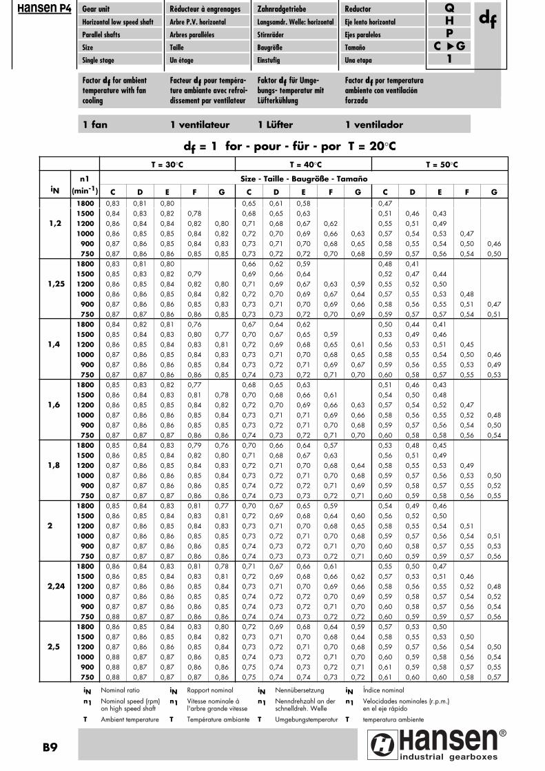
Gear unitHorizontal low speed shaft
Parallel shafts
Size
Single stage
Réducteur à engrenagesArbre P.V. horizontal
Arbres parallèles
Taille
Un étage
ZahnradgetriebeLangsamdr. Welle: horizontal
Stirnräder
Baugröße
Einstufig
ReductorEje lento horizontal
Ejes paralelos
Tamaño
Una etapa
PH
C G1
Qdf
ansen
Factor df for ambienttemperature with fancooling
Facteur df pour tempéra-ture ambiante avec refroi-dissement par ventilateur
Faktor df für Umge-bungs- temperatur mitLüfterkühlung
Factor df por temperaturaambiente con ventilaciónforzada
T = 30°C T = 40°C T = 50°C
n1 Size - Taille - Baugröße - TamañoiN (min-1) C D E F G C D E F G C D E F G
1800 0,83 0,81 0,80 0,65 0,61 0,58 0,471500 0,84 0,83 0,82 0,78 0,68 0,65 0,63 0,51 0,46 0,43
1,2 1200 0,86 0,84 0,84 0,82 0,80 0,71 0,68 0,67 0,62 0,55 0,51 0,491000 0,86 0,85 0,85 0,84 0,82 0,72 0,70 0,69 0,66 0,63 0,57 0,54 0,53 0,47
900 0,87 0,86 0,85 0,84 0,83 0,73 0,71 0,70 0,68 0,65 0,58 0,55 0,54 0,50 0,46750 0,87 0,86 0,86 0,85 0,85 0,73 0,72 0,72 0,70 0,68 0,59 0,57 0,56 0,54 0,50
1800 0,83 0,81 0,80 0,66 0,62 0,59 0,48 0,411500 0,85 0,83 0,82 0,79 0,69 0,66 0,64 0,52 0,47 0,44
1,25 1200 0,86 0,85 0,84 0,82 0,80 0,71 0,69 0,67 0,63 0,59 0,55 0,52 0,501000 0,86 0,86 0,85 0,84 0,82 0,72 0,70 0,69 0,67 0,64 0,57 0,55 0,53 0,48
900 0,87 0,86 0,86 0,85 0,83 0,73 0,71 0,70 0,69 0,66 0,58 0,56 0,55 0,51 0,47750 0,87 0,87 0,86 0,86 0,85 0,73 0,73 0,72 0,70 0,69 0,59 0,57 0,57 0,54 0,51
1800 0,84 0,82 0,81 0,76 0,67 0,64 0,62 0,50 0,44 0,411500 0,85 0,84 0,83 0,80 0,77 0,70 0,67 0,65 0,59 0,53 0,49 0,46
1,4 1200 0,86 0,85 0,84 0,83 0,81 0,72 0,69 0,68 0,65 0,61 0,56 0,53 0,51 0,451000 0,87 0,86 0,85 0,84 0,83 0,73 0,71 0,70 0,68 0,65 0,58 0,55 0,54 0,50 0,46
900 0,87 0,86 0,86 0,85 0,84 0,73 0,72 0,71 0,69 0,67 0,59 0,56 0,55 0,53 0,49750 0,87 0,87 0,86 0,86 0,85 0,74 0,73 0,72 0,71 0,70 0,60 0,58 0,57 0,55 0,53
1800 0,85 0,83 0,82 0,77 0,68 0,65 0,63 0,51 0,46 0,431500 0,86 0,84 0,83 0,81 0,78 0,70 0,68 0,66 0,61 0,54 0,50 0,48
1,6 1200 0,86 0,85 0,85 0,84 0,82 0,72 0,70 0,69 0,66 0,63 0,57 0,54 0,52 0,471000 0,87 0,86 0,86 0,85 0,84 0,73 0,71 0,71 0,69 0,66 0,58 0,56 0,55 0,52 0,48
900 0,87 0,86 0,86 0,85 0,85 0,73 0,72 0,71 0,70 0,68 0,59 0,57 0,56 0,54 0,50750 0,87 0,87 0,87 0,86 0,86 0,74 0,73 0,72 0,71 0,70 0,60 0,58 0,58 0,56 0,54
1800 0,85 0,84 0,83 0,79 0,76 0,70 0,66 0,64 0,57 0,53 0,48 0,451500 0,86 0,85 0,84 0,82 0,80 0,71 0,68 0,67 0,63 0,56 0,51 0,49
1,8 1200 0,87 0,86 0,85 0,84 0,83 0,72 0,71 0,70 0,68 0,64 0,58 0,55 0,53 0,491000 0,87 0,86 0,86 0,85 0,84 0,73 0,72 0,71 0,70 0,68 0,59 0,57 0,56 0,53 0,50
900 0,87 0,87 0,86 0,86 0,85 0,74 0,72 0,72 0,71 0,69 0,59 0,58 0,57 0,55 0,52750 0,87 0,87 0,87 0,86 0,86 0,74 0,73 0,73 0,72 0,71 0,60 0,59 0,58 0,56 0,55
1800 0,85 0,84 0,83 0,81 0,77 0,70 0,67 0,65 0,59 0,54 0,49 0,461500 0,86 0,85 0,84 0,83 0,81 0,72 0,69 0,68 0,64 0,60 0,56 0,52 0,50
2 1200 0,87 0,86 0,85 0,84 0,83 0,73 0,71 0,70 0,68 0,65 0,58 0,55 0,54 0,511000 0,87 0,86 0,86 0,85 0,85 0,73 0,72 0,71 0,70 0,68 0,59 0,57 0,56 0,54 0,51
900 0,87 0,87 0,86 0,86 0,85 0,74 0,73 0,72 0,71 0,70 0,60 0,58 0,57 0,55 0,53750 0,87 0,87 0,87 0,86 0,86 0,74 0,73 0,73 0,72 0,71 0,60 0,59 0,59 0,57 0,56
1800 0,86 0,84 0,83 0,81 0,78 0,71 0,67 0,66 0,61 0,55 0,50 0,471500 0,86 0,85 0,84 0,83 0,81 0,72 0,69 0,68 0,66 0,62 0,57 0,53 0,51 0,46
2,24 1200 0,87 0,86 0,86 0,85 0,84 0,73 0,71 0,70 0,69 0,66 0,58 0,56 0,55 0,52 0,481000 0,87 0,86 0,86 0,85 0,85 0,74 0,72 0,72 0,70 0,69 0,59 0,58 0,57 0,54 0,52
900 0,87 0,87 0,86 0,86 0,85 0,74 0,73 0,72 0,71 0,70 0,60 0,58 0,57 0,56 0,54750 0,88 0,87 0,87 0,86 0,86 0,74 0,74 0,73 0,72 0,72 0,60 0,59 0,59 0,57 0,56
1800 0,86 0,85 0,84 0,83 0,80 0,72 0,69 0,68 0,64 0,59 0,57 0,53 0,501500 0,87 0,86 0,85 0,84 0,82 0,73 0,71 0,70 0,68 0,64 0,58 0,55 0,53 0,50
2,5 1200 0,87 0,86 0,86 0,85 0,84 0,73 0,72 0,71 0,70 0,68 0,59 0,57 0,56 0,54 0,501000 0,88 0,87 0,87 0,86 0,85 0,74 0,73 0,72 0,71 0,70 0,60 0,59 0,58 0,56 0,54
900 0,88 0,87 0,87 0,86 0,86 0,75 0,74 0,73 0,72 0,71 0,61 0,59 0,58 0,57 0,55750 0,88 0,87 0,87 0,87 0,86 0,75 0,74 0,74 0,73 0,72 0,61 0,60 0,60 0,58 0,57
iN Índice nominal
n1 Velocidades nominales (r.p.m.) en el eje rápido
T temperatura ambiente
iN Rapport nominal
n1 Vitesse nominale à l'arbre grande vitesse
T Température ambiante
iN Nennübersetzung
n1 Nenndrehzahl an der schnelldreh. Welle
T Umgebungstemperatur
iN Nominal ratio
n1 Nominal speed (rpm) on high speed shaft
T Ambient temperature
df = 1 for - pour - für - por T = 20°C
1 fan 1 ventilateur 1 Lüfter 1 ventilador
B9
Pagina: 1
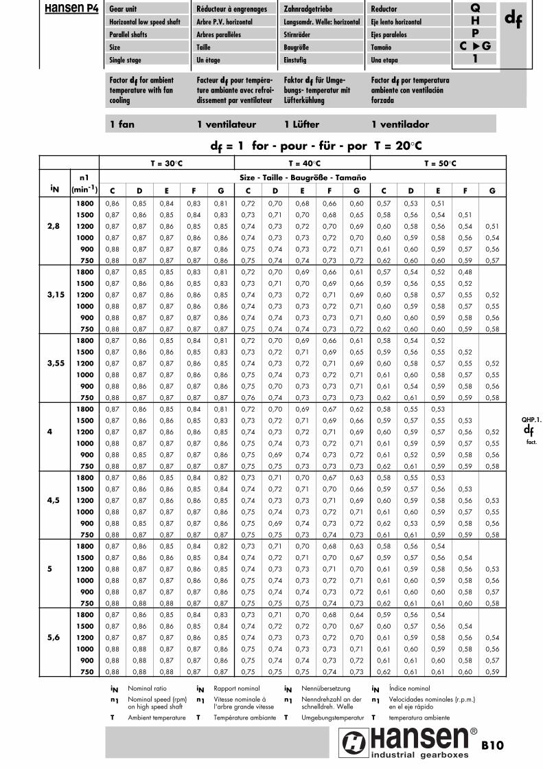
Gear unitHorizontal low speed shaft
Parallel shafts
Size
Single stage
Réducteur à engrenagesArbre P.V. horizontal
Arbres parallèles
Taille
Un étage
ZahnradgetriebeLangsamdr. Welle: horizontal
Stirnräder
Baugröße
Einstufig
ReductorEje lento horizontal
Ejes paralelos
Tamaño
Una etapa
PH
C G1
Qdf
ansen
Factor df for ambienttemperature with fancooling
Facteur df pour tempéra-ture ambiante avec refroi-dissement par ventilateur
Faktor df für Umge-bungs- temperatur mitLüfterkühlung
Factor df por temperaturaambiente con ventilaciónforzada
T = 30°C T = 40°C T = 50°C
n1 Size - Taille - Baugröße - TamañoiN (min-1) C D E F G C D E F G C D E F G
1800 0,86 0,85 0,84 0,83 0,81 0,72 0,70 0,68 0,66 0,60 0,57 0,53 0,51
1500 0,87 0,86 0,85 0,84 0,83 0,73 0,71 0,70 0,68 0,65 0,58 0,56 0,54 0,51
2,8 1200 0,87 0,87 0,86 0,85 0,85 0,74 0,73 0,72 0,70 0,69 0,60 0,58 0,56 0,54 0,51
1000 0,87 0,87 0,87 0,86 0,86 0,74 0,73 0,73 0,72 0,70 0,60 0,59 0,58 0,56 0,54
900 0,88 0,87 0,87 0,87 0,86 0,75 0,74 0,73 0,72 0,71 0,61 0,60 0,59 0,57 0,56
750 0,88 0,87 0,87 0,87 0,86 0,75 0,74 0,74 0,73 0,72 0,62 0,60 0,60 0,59 0,57
1800 0,87 0,85 0,85 0,83 0,81 0,72 0,70 0,69 0,66 0,61 0,57 0,54 0,52 0,48
1500 0,87 0,86 0,86 0,85 0,83 0,73 0,71 0,70 0,69 0,66 0,59 0,56 0,55 0,52
3,15 1200 0,87 0,87 0,86 0,86 0,85 0,74 0,73 0,72 0,71 0,69 0,60 0,58 0,57 0,55 0,52
1000 0,88 0,87 0,87 0,86 0,86 0,74 0,73 0,73 0,72 0,71 0,60 0,59 0,58 0,57 0,55
900 0,88 0,87 0,87 0,87 0,86 0,74 0,74 0,73 0,73 0,71 0,60 0,60 0,59 0,58 0,56
750 0,88 0,87 0,87 0,87 0,87 0,75 0,74 0,74 0,73 0,72 0,62 0,60 0,60 0,59 0,58
1800 0,87 0,86 0,85 0,84 0,81 0,72 0,70 0,69 0,66 0,61 0,58 0,54 0,52
1500 0,87 0,86 0,86 0,85 0,83 0,73 0,72 0,71 0,69 0,65 0,59 0,56 0,55 0,52
3,55 1200 0,87 0,87 0,87 0,86 0,85 0,74 0,73 0,72 0,71 0,69 0,60 0,58 0,57 0,55 0,52
1000 0,88 0,87 0,87 0,86 0,86 0,75 0,74 0,73 0,72 0,71 0,61 0,60 0,58 0,57 0,55
900 0,88 0,86 0,87 0,87 0,86 0,75 0,70 0,73 0,73 0,71 0,61 0,54 0,59 0,58 0,56
750 0,88 0,87 0,87 0,87 0,87 0,76 0,74 0,73 0,73 0,73 0,62 0,61 0,59 0,59 0,58
1800 0,87 0,86 0,85 0,84 0,81 0,72 0,70 0,69 0,67 0,62 0,58 0,55 0,53
1500 0,87 0,86 0,86 0,85 0,83 0,73 0,72 0,71 0,69 0,66 0,59 0,57 0,55 0,53
4 1200 0,87 0,87 0,86 0,86 0,85 0,74 0,73 0,72 0,71 0,69 0,60 0,59 0,57 0,56 0,52
1000 0,88 0,87 0,87 0,87 0,86 0,75 0,74 0,73 0,72 0,71 0,61 0,59 0,59 0,57 0,55
900 0,88 0,85 0,87 0,87 0,86 0,75 0,69 0,74 0,73 0,72 0,61 0,52 0,59 0,58 0,56
750 0,88 0,87 0,87 0,87 0,87 0,75 0,75 0,73 0,73 0,73 0,62 0,61 0,59 0,59 0,58
1800 0,87 0,86 0,85 0,84 0,82 0,73 0,71 0,70 0,67 0,63 0,58 0,55 0,53
1500 0,87 0,86 0,86 0,85 0,84 0,74 0,72 0,71 0,70 0,66 0,59 0,57 0,56 0,53
4,5 1200 0,87 0,87 0,86 0,86 0,85 0,74 0,73 0,73 0,71 0,69 0,60 0,59 0,58 0,56 0,53
1000 0,88 0,87 0,87 0,87 0,86 0,75 0,74 0,73 0,72 0,71 0,61 0,60 0,59 0,57 0,55
900 0,88 0,85 0,87 0,87 0,86 0,75 0,69 0,74 0,73 0,72 0,62 0,53 0,59 0,58 0,56
750 0,88 0,87 0,87 0,87 0,87 0,75 0,75 0,73 0,74 0,73 0,61 0,61 0,59 0,59 0,58
1800 0,87 0,86 0,85 0,84 0,82 0,73 0,71 0,70 0,68 0,63 0,58 0,56 0,54
1500 0,87 0,86 0,86 0,85 0,84 0,74 0,72 0,71 0,70 0,67 0,59 0,57 0,56 0,54
5 1200 0,88 0,87 0,87 0,86 0,85 0,74 0,73 0,73 0,71 0,70 0,61 0,59 0,58 0,56 0,53
1000 0,88 0,87 0,87 0,86 0,86 0,75 0,74 0,73 0,72 0,71 0,61 0,60 0,59 0,58 0,56
900 0,88 0,87 0,87 0,87 0,86 0,75 0,74 0,74 0,73 0,72 0,61 0,60 0,60 0,58 0,57
750 0,88 0,88 0,88 0,87 0,87 0,75 0,75 0,75 0,74 0,73 0,62 0,61 0,61 0,60 0,58
1800 0,87 0,86 0,85 0,84 0,83 0,73 0,71 0,70 0,68 0,64 0,59 0,56 0,54
1500 0,87 0,86 0,86 0,85 0,84 0,74 0,72 0,72 0,70 0,67 0,60 0,57 0,56 0,54
5,6 1200 0,87 0,87 0,87 0,86 0,85 0,74 0,73 0,73 0,72 0,70 0,61 0,59 0,58 0,56 0,54
1000 0,88 0,88 0,87 0,87 0,86 0,75 0,74 0,73 0,73 0,71 0,61 0,60 0,59 0,58 0,56
900 0,88 0,88 0,87 0,87 0,86 0,75 0,74 0,74 0,73 0,72 0,61 0,61 0,60 0,58 0,57
750 0,88 0,88 0,88 0,87 0,87 0,75 0,75 0,75 0,74 0,73 0,62 0,61 0,61 0,60 0,59
iN Índice nominal
n1 Velocidades nominales (r.p.m.) en el eje rápido
T temperatura ambiente
iN Rapport nominal
n1 Vitesse nominale à l'arbre grande vitesse
T Température ambiante
iN Nennübersetzung
n1 Nenndrehzahl an der schnelldreh. Welle
T Umgebungstemperatur
iN Nominal ratio
n1 Nominal speed (rpm) on high speed shaft
T Ambient temperature
df = 1 for - pour - für - por T = 20°C
1 fan 1 ventilateur 1 Lüfter 1 ventilador
QHP.1.
df
fact.
B10
Pagina: 1

Gear unitHorizontal low speed shaft
Parallel shafts
Size
Single stage
Réducteur à engrenagesArbre P.V. horizontal
Arbres parallèles
Taille
Un étage
ZahnradgetriebeLangsamdr. Welle: horizontal
Stirnräder
Baugröße
Einstufig
ReductorEje lento horizontal
Ejes paralelos
Tamaño
Una etapa
PH
C G1
Qdff
ansen
Factor dff for ambienttemperature with fancooling
Facteur dff pour tempéra-ture ambiante avec refroi-dissement par ventilateur
Faktor dff für Umge-bungs- temperatur mitLüfterkühlung
Factor dff por temperatu-ra ambiente conventilación forzada
T = 30°C T = 40°C T = 50°C
n1 Size - Taille - Baugröße - TamañoiN (min-1) C D E F G C D E F G C D E F G
1800 0,85 0,83 0,83 0,79 0,75 0,69 0,66 0,65 0,57 0,52 0,47 0,461500 0,86 0,84 0,84 0,82 0,79 0,71 0,68 0,67 0,63 0,58 0,55 0,51 0,50 0,42
1,2 1200 0,86 0,85 0,85 0,84 0,82 0,72 0,70 0,69 0,67 0,64 0,57 0,54 0,53 0,49 0,441000 0,87 0,86 0,86 0,85 0,84 0,73 0,71 0,71 0,69 0,67 0,58 0,56 0,55 0,52 0,49
900 0,87 0,86 0,86 0,85 0,85 0,73 0,72 0,71 0,70 0,68 0,59 0,57 0,56 0,54 0,51750 0,87 0,87 0,87 0,86 0,86 0,74 0,73 0,72 0,71 0,70 0,60 0,58 0,58 0,56 0,54
1800 0,85 0,84 0,83 0,79 0,76 0,69 0,66 0,65 0,58 0,53 0,48 0,471500 0,86 0,85 0,84 0,83 0,80 0,71 0,68 0,68 0,64 0,59 0,55 0,51 0,50 0,44
1,25 1200 0,86 0,85 0,85 0,84 0,83 0,72 0,70 0,70 0,68 0,64 0,57 0,54 0,53 0,49 0,451000 0,87 0,86 0,86 0,85 0,84 0,73 0,72 0,71 0,69 0,67 0,58 0,56 0,56 0,53 0,49
900 0,87 0,86 0,86 0,85 0,85 0,73 0,72 0,72 0,70 0,69 0,59 0,57 0,57 0,54 0,51750 0,87 0,87 0,87 0,86 0,86 0,74 0,73 0,73 0,71 0,71 0,60 0,58 0,58 0,56 0,54
1800 0,85 0,84 0,83 0,80 0,77 0,70 0,67 0,66 0,60 0,54 0,49 0,481500 0,86 0,85 0,84 0,83 0,81 0,71 0,69 0,68 0,65 0,61 0,56 0,52 0,51 0,46
1,4 1200 0,87 0,86 0,85 0,84 0,83 0,72 0,71 0,70 0,68 0,66 0,58 0,55 0,54 0,51 0,471000 0,87 0,86 0,86 0,85 0,85 0,73 0,72 0,71 0,70 0,68 0,59 0,57 0,56 0,54 0,51
900 0,87 0,87 0,86 0,86 0,85 0,73 0,72 0,72 0,71 0,69 0,59 0,58 0,57 0,55 0,53750 0,87 0,87 0,87 0,86 0,86 0,74 0,73 0,73 0,72 0,71 0,60 0,59 0,58 0,57 0,55
1800 0,85 0,84 0,84 0,81 0,78 0,70 0,68 0,67 0,61 0,55 0,54 0,50 0,49 0,401500 0,86 0,85 0,85 0,83 0,81 0,72 0,69 0,69 0,66 0,62 0,56 0,53 0,52 0,47
1,6 1200 0,87 0,86 0,86 0,85 0,84 0,73 0,71 0,70 0,69 0,66 0,58 0,55 0,55 0,52 0,481000 0,87 0,86 0,86 0,85 0,85 0,73 0,72 0,72 0,70 0,69 0,59 0,57 0,56 0,54 0,52
900 0,87 0,87 0,86 0,86 0,85 0,74 0,73 0,72 0,71 0,70 0,60 0,58 0,57 0,55 0,53750 0,87 0,87 0,87 0,86 0,86 0,74 0,73 0,73 0,72 0,71 0,60 0,59 0,59 0,57 0,56
1800 0,86 0,84 0,84 0,82 0,80 0,71 0,68 0,67 0,64 0,59 0,55 0,51 0,50 0,431500 0,86 0,85 0,85 0,84 0,82 0,72 0,70 0,69 0,67 0,64 0,57 0,54 0,53 0,48
1,8 1200 0,87 0,86 0,86 0,85 0,84 0,73 0,71 0,71 0,69 0,67 0,59 0,56 0,55 0,53 0,491000 0,87 0,87 0,86 0,86 0,85 0,74 0,73 0,72 0,71 0,70 0,59 0,58 0,57 0,55 0,53
900 0,87 0,87 0,87 0,86 0,86 0,74 0,73 0,73 0,71 0,71 0,60 0,58 0,58 0,56 0,55750 0,87 0,87 0,87 0,87 0,86 0,74 0,74 0,73 0,72 0,72 0,60 0,59 0,59 0,58 0,57
1800 0,86 0,85 0,84 0,83 0,80 0,71 0,69 0,68 0,65 0,60 0,56 0,52 0,50 0,451500 0,87 0,85 0,85 0,84 0,83 0,72 0,70 0,70 0,67 0,65 0,57 0,54 0,53 0,49 0,45
2 1200 0,87 0,86 0,86 0,85 0,84 0,73 0,72 0,71 0,70 0,68 0,59 0,56 0,56 0,53 0,501000 0,87 0,87 0,86 0,86 0,85 0,74 0,73 0,72 0,71 0,70 0,60 0,58 0,57 0,55 0,54
900 0,87 0,87 0,87 0,86 0,86 0,74 0,73 0,73 0,72 0,71 0,60 0,59 0,58 0,56 0,55750 0,88 0,87 0,87 0,87 0,86 0,75 0,74 0,73 0,72 0,72 0,61 0,60 0,59 0,58 0,57
1800 0,86 0,85 0,84 0,83 0,81 0,72 0,69 0,68 0,65 0,61 0,56 0,52 0,51 0,461500 0,87 0,86 0,85 0,84 0,83 0,73 0,70 0,70 0,68 0,65 0,58 0,55 0,54 0,50 0,46
2,24 1200 0,87 0,86 0,86 0,85 0,85 0,73 0,72 0,71 0,70 0,69 0,59 0,57 0,56 0,54 0,511000 0,87 0,87 0,87 0,86 0,85 0,74 0,73 0,72 0,71 0,70 0,60 0,58 0,58 0,56 0,54
900 0,87 0,87 0,87 0,86 0,86 0,74 0,73 0,73 0,72 0,71 0,60 0,59 0,58 0,57 0,55750 0,88 0,87 0,87 0,87 0,86 0,75 0,74 0,74 0,73 0,72 0,61 0,60 0,59 0,58 0,57
1800 0,87 0,85 0,85 0,84 0,82 0,73 0,70 0,69 0,67 0,63 0,58 0,54 0,53 0,491500 0,87 0,86 0,86 0,85 0,84 0,73 0,71 0,71 0,69 0,66 0,59 0,56 0,55 0,53 0,48
2,5 1200 0,87 0,87 0,86 0,86 0,85 0,74 0,73 0,72 0,71 0,69 0,60 0,58 0,57 0,55 0,531000 0,88 0,87 0,87 0,86 0,86 0,74 0,73 0,73 0,72 0,71 0,61 0,59 0,59 0,57 0,55
900 0,88 0,87 0,87 0,87 0,86 0,75 0,74 0,73 0,73 0,72 0,61 0,60 0,59 0,58 0,56750 0,88 0,87 0,87 0,87 0,87 0,75 0,74 0,74 0,73 0,72 0,62 0,60 0,60 0,59 0,58
iN Índice nominal
n1 Velocidades nominales (r.p.m.) en el eje rápido
T temperatura ambiente
iN Rapport nominal
n1 Vitesse nominale à l'arbre grande vitesse
T Température ambiante
iN Nennübersetzung
n1 Nenndrehzahl an der schnelldreh. Welle
T Umgebungstemperatur
iN Nominal ratio
n1 Nominal speed (rpm) on high speed shaft
T Ambient temperature
dff = 1 for - pour - für - por T = 20°C
2 fans 2 ventilateurs 2 Lüfter 2 ventiladores
B11
Pagina: 1
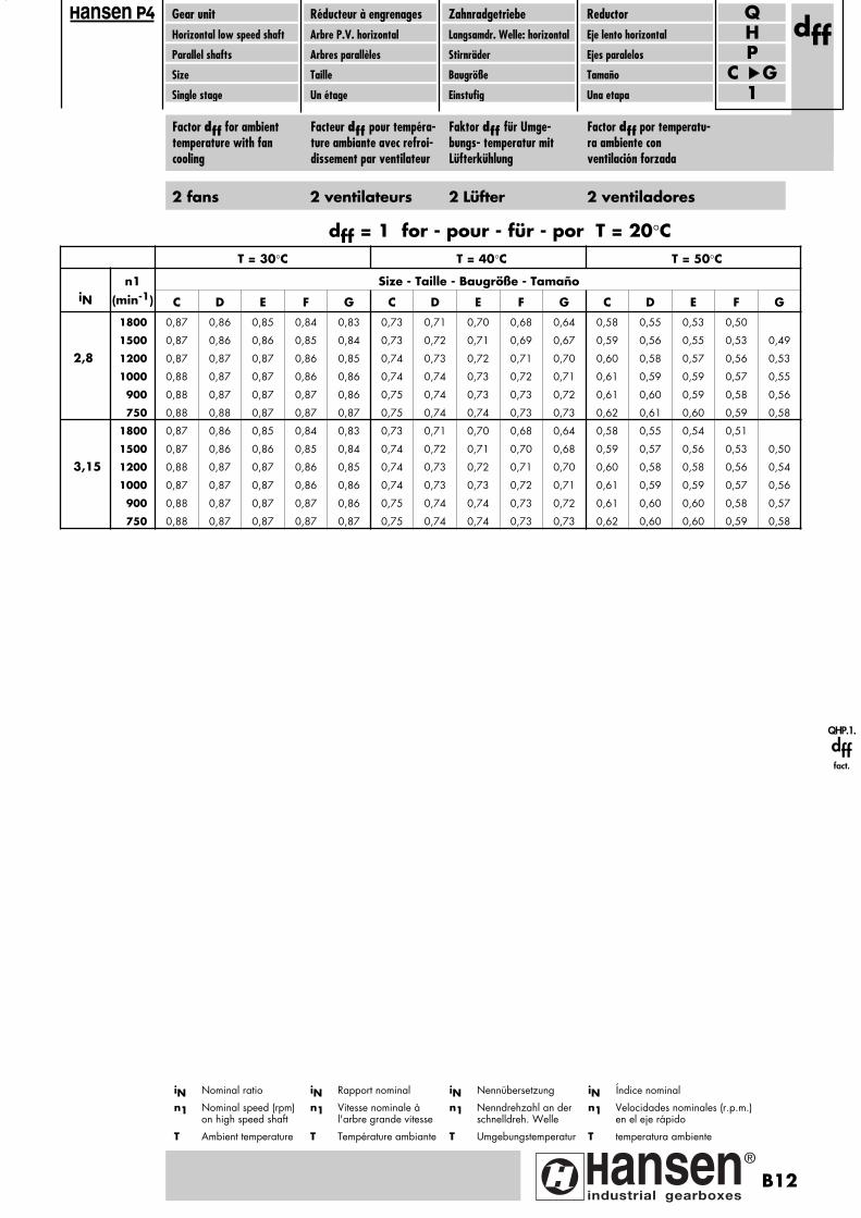
Gear unitHorizontal low speed shaft
Parallel shafts
Size
Single stage
Réducteur à engrenagesArbre P.V. horizontal
Arbres parallèles
Taille
Un étage
ZahnradgetriebeLangsamdr. Welle: horizontal
Stirnräder
Baugröße
Einstufig
ReductorEje lento horizontal
Ejes paralelos
Tamaño
Una etapa
PH
C G1
Qdff
ansen
Factor dff for ambienttemperature with fancooling
Facteur dff pour tempéra-ture ambiante avec refroi-dissement par ventilateur
Faktor dff für Umge-bungs- temperatur mitLüfterkühlung
Factor dff por temperatu-ra ambiente conventilación forzada
T = 30°C T = 40°C T = 50°C
n1 Size - Taille - Baugröße - TamañoiN (min-1) C D E F G C D E F G C D E F G
1800 0,87 0,86 0,85 0,84 0,83 0,73 0,71 0,70 0,68 0,64 0,58 0,55 0,53 0,50
1500 0,87 0,86 0,86 0,85 0,84 0,73 0,72 0,71 0,69 0,67 0,59 0,56 0,55 0,53 0,49
2,8 1200 0,87 0,87 0,87 0,86 0,85 0,74 0,73 0,72 0,71 0,70 0,60 0,58 0,57 0,56 0,53
1000 0,88 0,87 0,87 0,86 0,86 0,74 0,74 0,73 0,72 0,71 0,61 0,59 0,59 0,57 0,55
900 0,88 0,87 0,87 0,87 0,86 0,75 0,74 0,73 0,73 0,72 0,61 0,60 0,59 0,58 0,56
750 0,88 0,88 0,87 0,87 0,87 0,75 0,74 0,74 0,73 0,73 0,62 0,61 0,60 0,59 0,58
1800 0,87 0,86 0,85 0,84 0,83 0,73 0,71 0,70 0,68 0,64 0,58 0,55 0,54 0,51
1500 0,87 0,86 0,86 0,85 0,84 0,74 0,72 0,71 0,70 0,68 0,59 0,57 0,56 0,53 0,50
3,15 1200 0,88 0,87 0,87 0,86 0,85 0,74 0,73 0,72 0,71 0,70 0,60 0,58 0,58 0,56 0,54
1000 0,87 0,87 0,87 0,86 0,86 0,74 0,73 0,73 0,72 0,71 0,61 0,59 0,59 0,57 0,56
900 0,88 0,87 0,87 0,87 0,86 0,75 0,74 0,74 0,73 0,72 0,61 0,60 0,60 0,58 0,57
750 0,88 0,87 0,87 0,87 0,87 0,75 0,74 0,74 0,73 0,73 0,62 0,60 0,60 0,59 0,58
iN Índice nominal
n1 Velocidades nominales (r.p.m.) en el eje rápido
T temperatura ambiente
iN Rapport nominal
n1 Vitesse nominale à l'arbre grande vitesse
T Température ambiante
iN Nennübersetzung
n1 Nenndrehzahl an der schnelldreh. Welle
T Umgebungstemperatur
iN Nominal ratio
n1 Nominal speed (rpm) on high speed shaft
T Ambient temperature
dff = 1 for - pour - für - por T = 20°C
2 fans 2 ventilateurs 2 Lüfter 2 ventiladores
QHP.1.
dff
fact.
B12
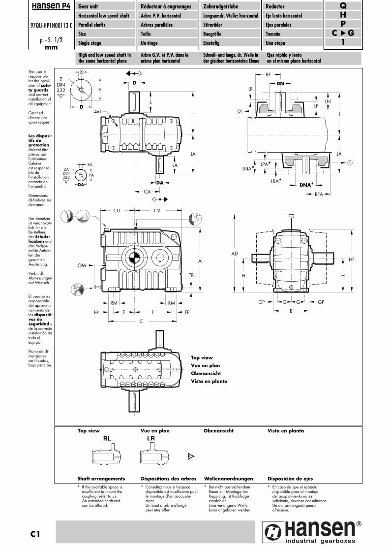
D
DA
CA
LA
JA
L
J4xT
CU CV
TR
RM RM
FP E F FP
C
AOM
G
H H
GGP GP
B
ADHF
DN
RF
LR
LPLN
J
DNA*RFA
LRA*
LPA*LNA*
JA
1
2
ZADIN332"D"
DA
YA
XA
Shaft arrangements Dispositions des arbres Wellenanordnungen Disposición de ejes
RL LR
X
Y
D
ZDIN332"D"
High and low speed shaft inthe same horizontal plane
Arbre G.V. et P.V. dans le même plan horizontal
Schnell- und langs. dr. Welle inder gleichen horizontalen Ebene
Ejes rápido y lento en el mismo plano horizontal
C1
97QU-HP1N00113 C
p. - S. 1/2mm
Gear unitHorizontal low speed shaft
Parallel shafts
Size
Single stage
Réducteur à engrenagesArbre P.V. horizontal
Arbres parallèles
Taille
Un étage
ZahnradgetriebeLangsamdr. Welle: horizontal
Stirnräder
Baugröße
Einstufig
ReductorEje lento horizontal
Ejes paralelos
Tamaño
Una etapa
PH
C G1
Qansen
The user is responsiblefor the provi-sion of safe-ty guardsand correct installation ofall equipment. Certified dimensionsupon request.
Les disposi-tifs deprotectiondoivent êtreprévus parl'utilisateur.Celui-ci est responsa-ble del'installationcorrecte del'ensemble. Dimensionsdéfinitives surdemande.
Der Benutzerist verantwort-lich für dieBeistellungder Schutz-hauben unddas fachge-mäße Aufstel-len der gesamten Ausrüstung. Verbindl. Abmessungenauf Wunsch.
El usuario esresponsabledel aprovisio-namiento delos dispositi-vos de seguridad yde la correctainstalación detodo el equipo.
Plano de di-mensionescertificadas,bajo petición.
Top view Vue en plan Obenansicht Vista en planta
* If the available space is insufficient to mount the coupling, refer to us.An extended shaft end can be offered.
* Consultez nous si l'espace disponible est insuffisante pourle montage d'un accouple-ment.Un bout d'arbre allongé peut être offert.
* Bei nicht ausreichendem Raum zur Montage der Kupplung, ist Rückfrage empfohlen.Eine verlängerte Welle kann angeboten werden.
* En caso de que el espacio disponible para el montaje del acoplamiento no es suficiente, sírvanse consultarnos.Un eje prolongado puede ofrecerse.
Top view
Vue en plan
Obenansicht
Vista en planta
Pagina: 1
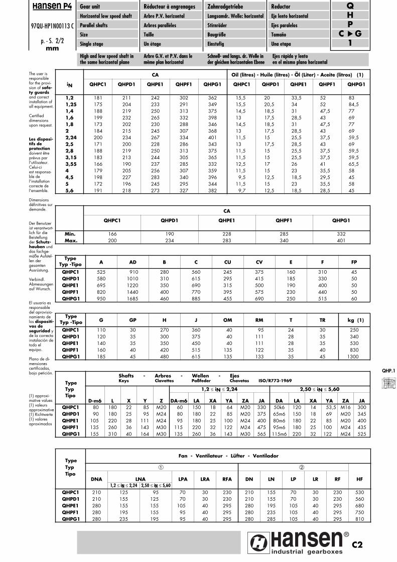
TypeTyp -Tipo A AD B C CU CV E F FP
QHPC1 525 910 280 560 245 375 160 310 45QHPD1 580 1010 310 615 295 415 185 330 50QHPE1 695 1220 350 690 315 500 190 400 50QHPF1 820 1440 400 770 395 575 230 440 50QHPG1 950 1685 460 885 455 690 250 515 60
Type Typ 1,2 ≤ iN ≤ 2,24 2,50 ≤ iN ≤ 5,60 Tipo
D-m6 L X Y Z DA-m6 LA XA YA ZA JA DA LA XA YA ZA JAQHPC1 80 180 22 85 M20 60 150 18 64 M20 330 50k6 120 14 53,5 M16 300QHPD1 90 180 25 95 M24 80 180 22 85 M20 375 65m6 150 18 69 M20 345QHPE1 105 220 28 111 M24 95 180 25 100 M24 400 80m6 180 22 85 M20 400QHPF1 135 260 36 143 M30 115 220 32 122 M24 475 95m6 180 25 100 M24 435QHPG1 155 310 40 164 M30 135 260 36 143 M30 565 115m6 220 32 122 M24 525
TypeTyp -Tipo G GP H J OM RM T TR kg (1)
QHPC1 110 30 270 360 40 95 24 30 250QHPD1 120 35 300 375 40 111 28 35 340QHPE1 140 35 350 450 40 111 28 35 530QHPF1 160 40 420 515 135 122 35 40 830QHPG1 185 45 480 615 135 133 35 45 1300
Shafts - Arbres - Wellen - Ejes Keys Clavettes Paßfeder Chavetas ISO/R773-1969
Type Typ ➀ ➁ Tipo
DNA LNA LPA LRA RFA DN LN LP LR RF HF1,2 ≤ iN ≤ 2,24 2,50 ≤ iN ≤ 5,60
QHPC1 210 125 95 70 30 230 210 155 70 30 230 530QHPD1 210 155 125 70 30 230 210 155 70 30 230 560QHPE1 280 155 155 105 40 295 280 195 105 40 295 680QHPF1 280 195 155 95 40 295 280 235 105 40 295 750QHPG1 280 235 195 95 40 295 280 285 105 40 295 810
Fan - Ventilateur - Lüfter - Ventilador
CA
QHPC1 QHPD1 QHPE1 QHPF1 QHPG1 QHPC1 QHPD1 QHPE1 QHPF1 QHPG1
1,2 181 211 242 302 362 15,5 20 33,5 52 831,25 175 204 233 291 349 15,5 20,5 34 52 84,51,4 188 219 250 313 375 14,5 18,5 31 47,5 771,6 199 232 265 332 398 13 17,5 28,5 43 691,8 173 202 230 288 346 14,5 18,5 31 47,5 772 184 215 245 307 368 13 17,5 28,5 43 692,24 200 234 267 334 401 11,5 15 25,5 37,5 59,52,5 171 200 228 286 343 13 17,5 28,5 43 692,8 188 219 250 313 375 11,5 15 25,5 37,5 59,53,15 183 213 244 305 365 11,5 15 25,5 37,5 59,53,55 166 190 237 285 332 12,5 17 26 41 65,54 179 205 256 307 359 11,5 15 23 35,5 584,5 198 227 283 340 396 9,5 12,5 18,5 29,5 455 172 196 245 295 344 11,5 15 23 35,5 585,6 191 218 273 327 382 9,7 12,5 18,5 28,5 45
iN
Oil (litres) - Huile (litres) - Öl (Liter) - Aceite (litros) (1)
97QU-HP1N00113 C
p. - S. 2/2mm
Gear unitHorizontal low speed shaft
Parallel shafts
Size
Single stage
Réducteur à engrenagesArbre P.V. horizontal
Arbres parallèles
Taille
Un étage
ZahnradgetriebeLangsamdr. Welle: horizontal
Stirnräder
Baugröße
Einstufig
ReductorEje lento horizontal
Ejes paralelos
Tamaño
Una etapa
PH
C G1
Qansen
(1) approxi-mative values(1) valeurs approximative(1) Richtwerte(1) valores aproximados
The user is responsiblefor the provi-sion of safe-ty guardsand correct installation ofall equipment. Certified dimensionsupon request.
Les disposi-tifs deprotectiondoivent êtreprévus parl'utilisateur.Celui-ci est responsa-ble del'installationcorrecte del'ensemble. Dimensionsdéfinitives surdemande.
Der Benutzerist verantwort-lich für dieBeistellungder Schutz-hauben unddas fachge-mäße Aufstel-len der gesamten Ausrüstung. Verbindl. Abmessungenauf Wunsch.
El usuario esresponsabledel aprovisio-namiento delos dispositi-vos de seguridad yde la correctainstalación detodo el equipo.
Plano de di-mensionescertificadas,bajo petición.
High and low speed shaft inthe same horizontal plane
Arbre G.V. et P.V. dans le même plan horizontal
Schnell- und langs. dr. Welle inder gleichen horizontalen Ebene
Ejes rápido y lento en el mismo plano horizontal
QHP.1
CA
QHPC1 QHPD1 QHPE1 QHPF1 QHPG1
Min. 166 190 228 285 332Max. 200 234 283 340 401
C2
Pagina: 1

The user is responsiblefor the provi-sion of safe-ty guardsand correct installation ofall equipment. Certified dimensionsupon request.
Les disposi-tifs deprotectiondoivent êtreprévus parl'utilisateur.Celui-ci est responsa-ble del'installationcorrecte del'ensemble. Dimensionsdéfinitives surdemande.
Der Benutzerist verantwort-lich für dieBeistellungder Schutz-hauben unddas fachge-mäße Aufstel-len der gesamten Ausrüstung. Verbindl. Abmessungenauf Wunsch.
El usuario esresponsabledel aprovisio-namiento delos dispositi-vos de seguridad yde la correctainstalación detodo el equi-po.
Plano de di-mensionescertificadas,bajo petición.
High speed shaft abovelow speed shaft
Arbre G.V. au dessus del'arbre P.V.
Schnelldr. Welle oberhalbder langsamdrehenden Welle
Eje rápido por encima del ejelento W
C3
97QU-HP1N00023 C
p. - S. 1/2mm
Gear unitHorizontal low speed shaft
Parallel shafts
Size
Single stage
Réducteur à engrenagesArbre P.V. horizontal
Arbres parallèles
Taille
Un étage
ZahnradgetriebeLangsamdr. Welle: horizontal
Stirnräder
Baugröße
Einstufig
ReductorEje lento horizontal
Ejes paralelos
Tamaño
Una etapa
PH
C G1
Qansen
DN
RF
LR
LP
LN
J
DNA*
RFA
LRA*
LPA*
LNA*
JA
12
D
DA
CA
LA
JA
L
J
G GGP GP
B
A
CU
CV
TR
BD
RM RM
FP
H
FPN N
BS
OM
4xT
HF
X
Y
D
ZDIN332"D"
ZADIN332"D"
DA
YA
XA
Shaft arrangements Dispositions des arbres Wellenanordnungen Disposición de ejes
Top view Vue en plan Obenansicht Vista en planta
RL LR
* If the available space is insufficient to mount the coupling, refer to us.An extended shaft end can be offered.
* Consultez nous si l'espace disponible est insuffisante pourle montage d'un accouple-ment.Un bout d'arbre allongé peut être offert.
* Bei nicht ausreichendem Raum zur Montage der Kupplung, ist Rückfrage empfohlen.Eine verlängerte Welle kann angeboten werden.
* En caso de que el espacio disponible para el montaje del acoplamiento no es suficiente, sírvanse consultarnos.Un eje prolongado puede ofrecerse.
Top view
Vue en plan
Obenansicht
Vista en planta
Pagina: 1

97QU-HP1N00023 C
p. - S. 2/2mm
Gear unitHorizontal low speed shaft
Parallel shafts
Size
Single stage
Réducteur à engrenagesArbre P.V. horizontal
Arbres parallèles
Taille
Un étage
ZahnradgetriebeLangsamdr. Welle: horizontal
Stirnräder
Baugröße
Einstufig
ReductorEje lento horizontal
Ejes paralelos
Tamaño
Una etapa
PH
C G1
Qansen
TypeTyp - Tipo A B BD BS CU CV FP G GP
QHPC1W 525 280 1215 360 240 375 45 110 30QHPD1W 580 310 1370 410 290 415 50 120 35QHPE1W 695 350 1600 460 310 500 50 140 35QHPF1W 820 400 1870 520 390 575 50 160 40QHPG1W 950 460 2200 610 450 690 60 185 45
Type Typ 1,2 ≤ iN ≤ 2,24 2,50 ≤ iN ≤ 5,60 Tipo D-m6 L X Y Z DA-m6 LA XA YA ZA JA DA LA XA YA ZA JA
QHPC1W 80 180 22 85 M20 60 150 18 64 M20 330 50k6 120 14 53,5 M16 300QHPD1W 90 180 25 95 M24 80 180 22 85 M20 375 65m6 150 18 69 M20 345QHPE1W 105 220 28 111 M24 95 180 25 100 M24 400 80m6 180 22 85 M20 400QHPF1W 135 260 36 143 M30 115 220 32 122 M24 475 95m6 180 25 100 M24 435QHPG1W 155 310 40 164 M30 135 260 36 143 M30 565 115m6 220 32 122 M24 525
TypeTyp - Tipo H J N OM RM T TR kg (1)
QHPC1W 270 360 135 40 95 24 30 250QHPD1W 300 375 155 40 111 28 35 340QHPE1W 350 450 180 40 111 28 35 530QHPF1W 420 515 210 135 122 35 40 830QHPG1W 480 615 245 135 133 35 45 1300
Shafts - Arbres - Wellen - Ejes Keys Clavettes Paßfeder Chavetas ISO/R773-1969
CA
QHPC1W QHPD1W QHPE1W QHPF1W QHPG1W QHPC1W QHPD1W QHPE1W QHPF1W QHPG1W
1,2 181 211 242 302 362 10 13,5 22 37 63,51,25 175 204 233 291 349 10 13,5 22 38 63,51,4 188 219 250 313 375 9 12,5 20 34,5 571,6 199 232 265 332 398 8 11 18,5 31 511,8 173 202 230 288 346 9 12,5 20 34,5 572 184 215 245 307 368 8 11 18,5 31 512,24 200 234 267 334 401 7 10 15 26 432,5 171 200 228 286 343 8 11 18,5 31 512,8 188 219 250 313 375 7 10 15 26 433,15 183 213 244 305 365 7 10 15 26 433,55 166 190 237 285 332 7,5 11 16,5 28,5 49,54 179 205 256 307 359 6,5 10 14 25 424,5 198 227 283 340 396 5,5 8 10 19 335 172 196 245 295 344 6,5 10 14 25 425,6 191 218 273 327 382 5,5 8 10 19 33
iN
Oil (litres) - Huile (litres) - Öl (Liter) - Aceite (litros) (1)
(1) approxi-mative values(1) valeurs approximative(1) Richtwerte(1) valores aproximados
The user is responsiblefor the provi-sion of safe-ty guardsand correct installation ofall equipment. Certified dimensionsupon request.
Les disposi-tifs deprotectiondoivent êtreprévus parl'utilisateur.Celui-ci est responsa-ble del'installationcorrecte del'ensemble. Dimensionsdéfinitives surdemande.
Der Benutzerist verantwort-lich für dieBeistellungder Schutz-hauben unddas fachge-mäße Aufstel-len der gesamten Ausrüstung. Verbindl. Abmessungenauf Wunsch.
El usuario esresponsabledel aprovisio-namiento delos dispositi-vos de seguridad yde la correctainstalación detodo el equipo.
Plano de di-mensionescertificadas,bajo petición.
High speed shaft abovelow speed shaft
Arbre G.V. au dessus del'arbre P.V.
Schnelldr. Welle oberhalbder langsamdrehenden Welle
Eje rápido por encima del ejelento W
Type Typ ➀ ➁ Tipo
DNA LNA LPA LRA RFA DN LN LP LR RF HF
1,2 ≤ iN ≤ 2,24 2,50 ≤ iN ≤ 5,60QHPC1W 210 125 95 70 30 230 210 155 70 30 230 530QHPD1W 210 155 125 70 30 230 210 155 70 30 230 560QHPE1W 280 155 155 105 40 295 280 195 105 40 295 680QHPF1W 280 195 155 95 40 295 280 235 105 40 295 750QHPG1W 280 235 195 95 40 295 280 285 105 40 295 810
Fan - Ventilateur - Lüfter - Ventilador
QHP.1W
CA
QHPC1W QHPD1W QHPE1W QHPF1W QHPG1W
Min. 166 190 228 285 332Max. 200 234 283 340 401
C4
Pagina: 1

C5
97QU-HP1NC0003 B
mm
Gear unitHorizontal low speed shaft
Parallel shafts
Size
Single stage
Réducteur à engrenagesArbre P.V. horizontal
Arbres parallèles
Taille
Un étage
ZahnradgetriebeLangsamdr. Welle: horizontal
Stirnräder
Baugröße
Einstufig
ReductorEje lento horizontal
Ejes paralelos
Tamaño
Una etapa
PH
C G1
Qansen
The user is responsiblefor the provi-sion of safe-ty guardsand correct installation ofall equipment. Certified dimensionsupon request.
Les disposi-tifs deprotectiondoivent êtreprévus parl'utilisateur.Celui-ci est responsa-ble del'installationcorrecte del'ensemble. Dimensionsdéfinitives surdemande.
Der Benutzerist verantwort-lich für dieBeistellungder Schutz-hauben unddas fachge-mäße Aufstel-len der gesamten Ausrüstung. Verbindl. Abmessungenauf Wunsch.
El usuario esresponsabledel aprovisio-namiento delos dispositi-vos de seguridad yde la correctainstalación detodo el equi-po.
Plano de di-mensionescertificadas,bajo petición.
OptionsCooling coil
OptionsSerpentin de refroidissement
OptionenKühlschlange
OpcionesSistemas de refrigeración
C4
C1= =
C3
C2
C4
C1
== C3
C2
Size - Taille - Baugröße - TamañoC D E F G
C1 475 515 600 675 790
C2 80 87 87 94,5 102
C3 42 42 42 126 126
C4 R 1/2"
High and low speed shaft inthe same horizontal plane
Arbre G.V. et P.V. dans le même plan horizontal
Schnell- und langs. dr. Welle inder gleichen horizontalen Ebene
Ejes rápido y lento en el mismo plano horizontal
High speed shaft abovelow speed shaft
Arbre G.V. au dessus del'arbre P.V.
Schnelldr. Welle oberhalbder langsamdrehenden Welle
Eje rápido por encima del ejelento W
Pagina: 1
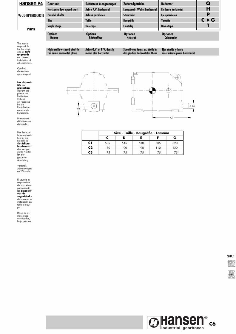
97QU-HP1ND0003 B
mm
Gear unitHorizontal low speed shaft
Parallel shafts
Size
Single stage
Réducteur à engrenagesArbre P.V. horizontal
Arbres parallèles
Taille
Un étage
ZahnradgetriebeLangsamdr. Welle: horizontal
Stirnräder
Baugröße
Einstufig
ReductorEje lento horizontal
Ejes paralelos
Tamaño
Una etapa
PH
C G1
Qansen
The user is responsiblefor the provi-sion of safe-ty guardsand correct installation ofall equipment. Certified dimensionsupon request.
Les disposi-tifs deprotectiondoivent êtreprévus parl'utilisateur.Celui-ci est responsa-ble del'installationcorrecte del'ensemble. Dimensionsdéfinitives surdemande.
Der Benutzerist verantwort-lich für dieBeistellungder Schutz-hauben unddas fachge-mäße Aufstel-len der gesamten Ausrüstung. Verbindl. Abmessungenauf Wunsch.
El usuario esresponsabledel aprovisio-namiento delos dispositi-vos de seguridad yde la correctainstalación detodo el equi-po.
Plano de di-mensionescertificadas,bajo petición.
OptionsHeater
OptionsRéchauffeur
OptionenHeizstab
OpcionesCalentador
C2
C1
C3
Size - Taille - Baugröße - TamañoC D E F G
C1 505 545 630 705 820
C2 80 90 90 110 120
C3 75 75 75 75 75
High and low speed shaft inthe same horizontal plane
Arbre G.V. et P.V. dans le même plan horizontal
Schnell- und langs. dr. Welle inder gleichen horizontalen Ebene
Ejes rápido y lento en el mismo plano horizontal
QHP.1.
C6
Pagina: 1
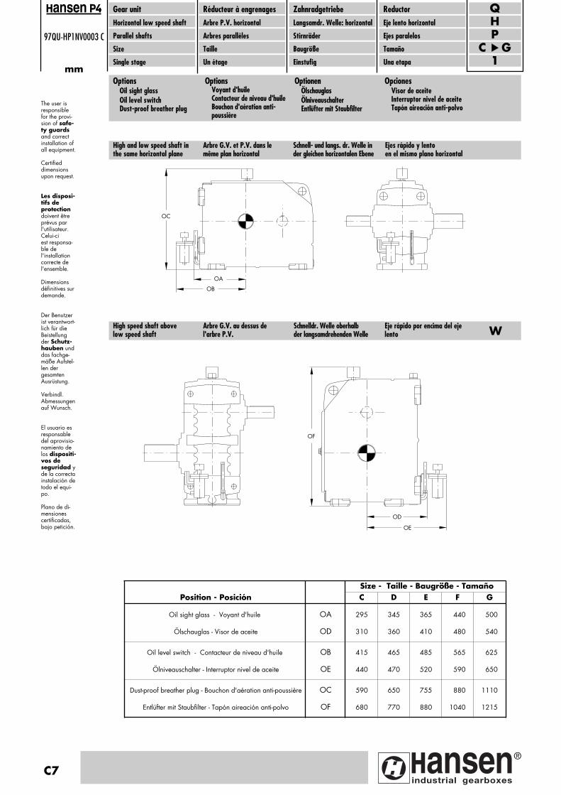
C7
97QU-HP1NV0003 C
mm
Gear unitHorizontal low speed shaft
Parallel shafts
Size
Single stage
Réducteur à engrenagesArbre P.V. horizontal
Arbres parallèles
Taille
Un étage
ZahnradgetriebeLangsamdr. Welle: horizontal
Stirnräder
Baugröße
Einstufig
ReductorEje lento horizontal
Ejes paralelos
Tamaño
Una etapa
PH
C G1
Qansen
The user is responsiblefor the provi-sion of safe-ty guardsand correct installation ofall equipment. Certified dimensionsupon request.
Les disposi-tifs deprotectiondoivent êtreprévus parl'utilisateur.Celui-ci est responsa-ble del'installationcorrecte del'ensemble. Dimensionsdéfinitives surdemande.
Der Benutzerist verantwort-lich für dieBeistellungder Schutz-hauben unddas fachge-mäße Aufstel-len der gesamten Ausrüstung. Verbindl. Abmessungenauf Wunsch.
El usuario esresponsabledel aprovisio-namiento delos dispositi-vos de seguridad yde la correctainstalación detodo el equi-po.
Plano de di-mensionescertificadas,bajo petición.
OptionsOil sight glassOil level switchDust-proof breather plug
OptionsVoyant d'huileContacteur de niveau d'huileBouchon d'aération anti-poussière
OptionenÖlschauglasÖlniveauschalterEntlüfter mit Staubfilter
OpcionesVisor de aceiteInterruptor nivel de aceiteTapón aireación anti-polvo
OC
OA
OB
OF
OD
OE
High and low speed shaft inthe same horizontal plane
Arbre G.V. et P.V. dans le même plan horizontal
Schnell- und langs. dr. Welle inder gleichen horizontalen Ebene
Ejes rápido y lento en el mismo plano horizontal
High speed shaft abovelow speed shaft
Arbre G.V. au dessus del'arbre P.V.
Schnelldr. Welle oberhalbder langsamdrehenden Welle
Eje rápido por encima del ejelento W
Size - Taille - Baugröße - TamañoPosition - Posición C D E F G
Oil sight glass - Voyant d'huile OA 295 345 365 440 500
Ölschauglas - Visor de aceite OD 310 360 410 480 540
Oil level switch - Contacteur de niveau d'huile OB 415 465 485 565 625
Ölniveauschalter - Interruptor nivel de aceite OE 440 470 520 590 650
Dust-proof breather plug - Bouchon d'aération anti-poussière OC 590 650 755 880 1110
Entlüfter mit Staubfilter - Tapón aireación anti-polvo OF 680 770 880 1040 1215
Pagina: 1
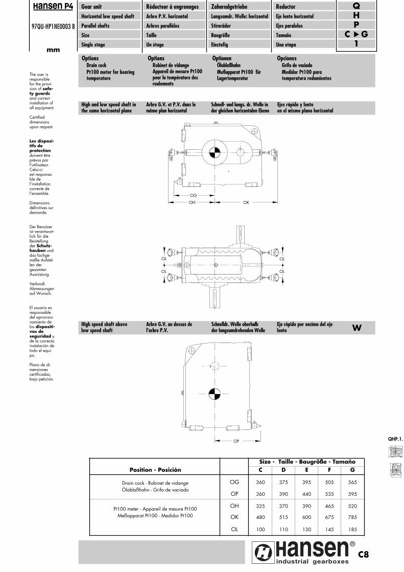
97QU-HP1NE0003 B
mm
Gear unitHorizontal low speed shaft
Parallel shafts
Size
Single stage
Réducteur à engrenagesArbre P.V. horizontal
Arbres parallèles
Taille
Un étage
ZahnradgetriebeLangsamdr. Welle: horizontal
Stirnräder
Baugröße
Einstufig
ReductorEje lento horizontal
Ejes paralelos
Tamaño
Una etapa
PH
C G1
Qansen
The user is responsiblefor the provi-sion of safe-ty guardsand correct installation ofall equipment. Certified dimensionsupon request.
Les disposi-tifs deprotectiondoivent êtreprévus parl'utilisateur.Celui-ci est responsa-ble del'installationcorrecte del'ensemble. Dimensionsdéfinitives surdemande.
Der Benutzerist verantwort-lich für dieBeistellungder Schutz-hauben unddas fachge-mäße Aufstel-len der gesamten Ausrüstung. Verbindl. Abmessungenauf Wunsch.
El usuario esresponsabledel aprovisio-namiento delos dispositi-vos de seguridad yde la correctainstalación detodo el equi-po.
Plano de di-mensionescertificadas,bajo petición.
OptionsDrain cockPt100 meter for bearing temperature
OptionsRobinet de vidangeAppareil de mesure Pt100 pour la température des roulements
OptionenÖlablaßhahnMeßapparat Pt100 für Lagertemperatur
OpcionesGrifo de vaciadoMedidor Pt100 para temperatura rodamientos
OG
OH OK
OL
OL
OL
OL
OP
High and low speed shaft inthe same horizontal plane
Arbre G.V. et P.V. dans le même plan horizontal
Schnell- und langs. dr. Welle inder gleichen horizontalen Ebene
Ejes rápido y lento en el mismo plano horizontal
High speed shaft abovelow speed shaft
Arbre G.V. au dessus del'arbre P.V.
Schnelldr. Welle oberhalbder langsamdrehenden Welle
Eje rápido por encima del ejelento W
Size - Taille - Baugröße - TamañoPosition - Posición C D E F G
Drain cock - Robinet de vidange OG 360 375 395 505 565Ölablaßhahn - Grifo de vaciado
OP 360 390 440 535 595
Pt100 meter - Appareil de mesure Pt100 OH 325 370 390 465 520
Meßapparat Pt100 - Medidor Pt100 OK 480 515 600 675 785
OL 100 110 130 145 185
QHP.1.
C8
Pagina: 1

Pagina: 1


See our worldwidesales & service network at
www.hansenindustrialgearboxes.com
DO
C-C
AM
233E
FDS/
0712
Hansen Industrial Transmissions nvLeonardo da Vincilaan 1B-2650 Edegem - BelgiumT. +32(0)3 450 12 11F. +32(0)3 450 12 20E. [email protected]
www.hansenindustrialgearboxes.com
DO
C-CA
M23
3EFD
S
Hansen Industrial Transmissions nv commits to
be a pioneering innovator. The production
of high performance gear units stems
from an interactive partnership with our
clients, the end users and the actively
engaged manpower of our global enter-
prise. Embracing design, manufacturing and
customer services, the company has grown
into a world leader in its field. Today, we set
standards for both product and working en-
vironment, inciting a knowing environment
to seize all new and inspiring technologies.
ww
w.h
anse
nin
dust
rial
gear
boxe
s.co
min
fo@
han
sen
ind
ust
rial
ge
arb
oxe
s.co
m tel. +32(0)3 450 12 11fax +32(0)3 450 12 20
Hansen Industrial Transmissions nvLeonardo da Vincilaan 12650 Edegem - AntwerpBelgium
see our worldwidesales & service network at
www.hansenindustrialgearboxes.com
Achterkaft heropmaken of aanpassen door drukkerij CopyCat