Standard Test Method for - Hanmi Corphanmicorp.net/MFG/Humboldt/GeoGauge/GeoGauge - As... ·...
15
1 Designation: H-4140-CBR Test Method for Using The Humboldt GeoGauge as an In-Place Index of CBR 1. Scope 1.1 This method covers the in-place evaluation of an in-place index of California Bearing Ratio (CBR) for a broad range of materials by using the Humboldt GeoGauge, an electro- mechanical means of in-place stiffness measurements. The GeoGauge and procedure provide a very rapid and simple means of testing so as to minimize interference and delay of construction, without penetrating the surface of the ground. The test method is intended for the evaluation of soils, aggregates and treated materials used in earthworks and roadways. The relationship presented in this method between CBR and the GeoGauge is general in nature and is therefore not guarantied to hold for all materials under all conditions. 1.2 The stiffness, in force per unit displacement, is determined by imparting a small measured force to the surface of the ground, measuring the resulting surface velocity and calculating the stiffness. This is done over a frequency range and the results are averaged. The average in-place stiffness is related to a laboratory CBR at the in-place moisture content. 1.3 The values tested in SI units are to be regarded as the standard. The inch-pound equivalents may be approximate. 1.4 This method does not purport to address all of the safety concerns, if any, associated with its use. It is the responsibility of the user of this method to establish appropriate safety and health practices and to determine the applicability of regulatory limitations prior to use.
Transcript of Standard Test Method for - Hanmi Corphanmicorp.net/MFG/Humboldt/GeoGauge/GeoGauge - As... ·...

1
Designation: H-4140-CBR
Test Method for Using The Humboldt GeoGauge as an In-Place Index of CBR
1. Scope
1.1 This method covers the in-place evaluation of an in-place index of California Bearing
Ratio (CBR) for a broad range of materials by using the Humboldt GeoGauge, an electro-
mechanical means of in-place stiffness measurements. The GeoGauge and procedure provide a
very rapid and simple means of testing so as to minimize interference and delay of construction,
without penetrating the surface of the ground. The test method is intended for the evaluation of
soils, aggregates and treated materials used in earthworks and roadways. The relationship
presented in this method between CBR and the GeoGauge is general in nature and is therefore
not guarantied to hold for all materials under all conditions.
1.2 The stiffness, in force per unit displacement, is determined by imparting a small
measured force to the surface of the ground, measuring the resulting surface velocity and
calculating the stiffness. This is done over a frequency range and the results are averaged. The
average in-place stiffness is related to a laboratory CBR at the in-place moisture content.
1.3 The values tested in SI units are to be regarded as the standard. The inch-pound
equivalents may be approximate.
1.4 This method does not purport to address all of the safety concerns, if any, associated
with its use. It is the responsibility of the user of this method to establish appropriate safety and
health practices and to determine the applicability of regulatory limitations prior to use.

H4140-CBR
2
2. Referenced Documents
2.1 ASTM Standards:
D 653 Terminology Relating to Soil, Rock and Contained
D 2216 Test Method for Laboratory Determination of Water (Moisture) Content of Soil and
Rock by Mass
D 6758-02 Standard Test Method for Measuring Stiffness and Apparent Modulus of Soil and
Soil-Aggregate In-Place by an Electro-Mechanical Method
C 144-04 Standard Specification for Aggregate for Masonry Mortar
D 1883-99 Standard Test Method for CBR (California Bearing Ratio) of Laboratory-
Compacted Soils
3. Terminology
3.1 Definitions:
3.1.1 For common definitions of terms in this method, refer to Terminology ASTM D
653.
3.1.2 kilo-pounds force per inch, klbf/in, n •
3.1.3 mega-newton per meter, MN/m, n •
3.1.4 stiffness, n • The ratio of change of force to the corresponding change in
translational deflection of an elastic element.
3.2 Definitions Specific to This Method:
H4140-CBR
3
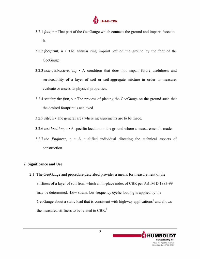
3.2.1 foot, n • That part of the GeoGauge which contacts the ground and imparts force to
it.
3.2.2 footprint, n • The annular ring imprint left on the ground by the foot of the
GeoGauge.
3.2.3 non-destructive, adj • A condition that does not impair future usefulness and
serviceability of a layer of soil or soil-aggregate mixture in order to measure,
evaluate or assess its physical properties.
3.2.4 seating the foot, v • The process of placing the GeoGauge on the ground such that
the desired footprint is achieved.
3.2.5 site, n • The general area where measurements are to be made.
3.2.6 test location, n • A specific location on the ground where a measurement is made.
3.2.7 the Engineer, n • A qualified individual directing the technical aspects of
construction
2. Significance and Use
2.1 The GeoGauge and procedure described provides a means for measurement of the
stiffness of a layer of soil from which an in-place index of CBR per ASTM D 1883-99
may be determined. Low strain, low frequency cyclic loading is applied by the
GeoGauge about a static load that is consistent with highway applications1 and allows
the measured stiffness to be related to CBR.2

H4140-CBR
2.2 This test method may used to evaluate the potential strength of subgrade, subbase, and
base course material, including treated materials for use in roadways and embankments.
The CBR value estimated in this method forms an integral part of several flexible
pavement design methods, specifically the empirical determination of layer thickness.
2.3 The rapid (75 sec. per measurement), non-penetrating nature of the method is suited to
QC/QA testing, i.e., it provides a means of testing that does not interfere with or delay
construction.
3. Humboldt GeoGauge
3.1 GeoGauge An electro-mechanical instrument, illustrated in Figure 1, capable of being
seated on the surface of the material under test and which provides a meaningful and
measurable stress level and a means of determining force and displacement.
3.2 Moist Sand A supply of clean mortar sand (e.g., ASTM C144-04) that contains 10% to
20% moisture by weight (sufficiently moist to clump in the palm of the hand). It will be
used to assist the seating of the rigid foot on rough and irregular ground surfaces or hard
and smooth ground surfaces.
3.3 Principle of Operation (ref. Fig. 1) The force applied by the shaker and transferred to
the ground is measured by differential displacement across the internal flexible plate.
Fdr = K flex (X2 − X1) + ω 2mint X1
where Fdr = force applied by the shaker
Kflex = stiffness of the flexible plate
4

H4140-CBR
X2 = displacement at the flexible plate
X1 = displacement at the rigid foot
ω = 2πf, where f is frequency
mint= mass of the internal components attached to the rigid foot and of the foot
At the frequencies of operation, the ground-input impedance will be dominantly stiffness
controlled.
Kgr = Fdr / X1
where
Kgr = stiffness of the ground
Figure 1: The Humboldt GeoGauge
5
H4140-CBR
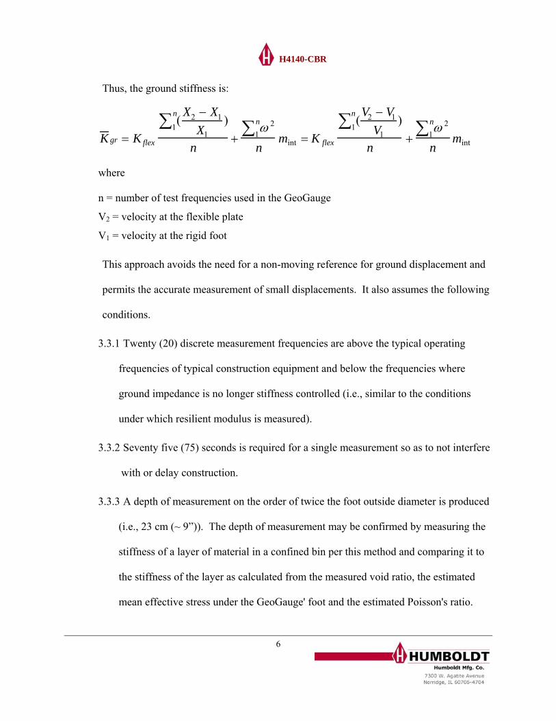
Thus, the ground stiffness is:
K gr = K flex
( X2 − X1
X1)
1
n∑n
+ω 2
1n∑n
mint = K flex
(V2 − V1
V1)
1
n∑n
+ω 2
1n∑n
mint
where
n = number of test frequencies used in the GeoGauge
V2 = velocity at the flexible plate
V1 = velocity at the rigid foot
This approach avoids the need for a non-moving reference for ground displacement and
permits the accurate measurement of small displacements. It also assumes the following
conditions.
3.3.1 Twenty (20) discrete measurement frequencies are above the typical operating
frequencies of typical construction equipment and below the frequencies where
ground impedance is no longer stiffness controlled (i.e., similar to the conditions
under which resilient modulus is measured).
3.3.2 Seventy five (75) seconds is required for a single measurement so as to not interfere
with or delay construction.
3.3.3 A depth of measurement on the order of twice the foot outside diameter is produced
(i.e., 23 cm (~ 9”)). The depth of measurement may be confirmed by measuring the
stiffness of a layer of material in a confined bin per this method and comparing it to
the stiffness of the layer as calculated from the measured void ratio, the estimated
mean effective stress under the GeoGauge' foot and the estimated Poisson's ratio.
6

H4140-CBR
7
3.3.4 The GeoGauge is immune to construction noise and vibration as much as is
practical.
3.3.5 The GeoGauge has a static weight sufficient to produce a meaningful stress on the
ground (i.e., 20.6 to 27.6 kPa (3 to 5 psi)).
3.3.6 The measurement does not densify the material being measured or otherwise
change its material properties. Periodic, repeated measurements (at least 10) at
selected locations where individual results are about equally distributed about the
mean of all results will indicate that the measurement has not densified the material.
3.3.7 The GeoGauge has a precision represented by a Coefficient of Variation (COV) of
typically 8.5% and bias represented by a COV of < 1%.
3.4 Refer to ASTM D 6758-02 for additional information regarding the GeoGauge and its
use. In the case of a conflict, this method takes precedence,
4. Calibration
4.1 Follow the procedure in Humboldt document H 4140-01. Calibration via the force-to-
displacement produced by moving a mass is directed as it will provide an absolute
reference for stiffness measurements. This is be done by rigidly attaching a mass of
known value to the foot of the GeoGauge and attaching the mass to isolation mounts
with a high frequency cut-off of ~ 5Hz. A measurement of stiffness in this configuration
should agree with the following equation within + 1%.

H4140-CBR
Keff =M(ω )2
1n∑
n where
Keff = stiffness (NM/m)
M = value of the moving mass (kg)
ω = 2πf, where f is frequency (Hz)
n = the number of frequencies used in the GeoGauge
6.2 Calibration of the GeoGauge is suggested every 12 months
f the calibration may be
s
1
conditions may not allow the precision of a laboratory calibration and so an appropriate
Figure 2: GeoGauge On Calibration Mass H-4140.?
6.3 When any stiffness measurement is in doubt, a field check o
needed. A check via the force-to-displacement produced by moving a known mass i
directed as it will provide an approximate reference for stiffness measurements (see 6.
& figure 3). Follow the procedure in Humboldt document H 4140-03. Note that field
8

H4140-CBR
tolerance should be assigned to the check (e.g., +/- 5% relative to the value of stiffness
expected).
dure
5. Proce
.1 Verify GeoGauge Operation (daily)
lace the GeoGauge on a field-check or Verifier mass (see 6.3) & make 3
ly turning it between measurements.
of the
5.2
5.2.1 ared ground approximately smooth. If the surface is
cm (1/4") of moist mortar
sand. Place the GeoGauge on the surface & turn it ~ 1/4 revolution if on sand or ~
5
Figure 3: GeoGauge On Verifier Mass H-4140.20
5.1.1 P
measurements, raising & random
5.1.2 The GeoGauge is operating properly if the average stiffness is within +/- 5%
value established in 6.1.
Establish GeoGauge Precision (once per material on a job)
Scrape a location of prep
smooth & hard or rough & irregular, pat in-place ~ 0.6
9

H4140-CBR
1/2 revolution if not on sand. Make a minimum of 3 measurements. Raise the
GeoGauge, assure that the footprint is relatively complete (see figure 4), smooth
away its footprint & turn the GeoGauge as before once replaced between
measurements. If the footprint is not relatively complete, discard the measurem
GeoGauge precision is sufficient if the Coefficient of Variation of the
measurements is < 8.5%.
ent.
5.2.2
5.3 eoGauge Measurements Used As An Index Of CBR
Gauge will
.2. Measure moisture content within approximately 0.6
TM D 2216 or equivalent. Record
5.3.2
Moisture content measurements will be made at a lesser frequency. The sample
G
Figure 4: Typical “Complete” Footprints
5.3.1 Measure stiffness with the GeoGauge at locations of interest. The Geo
be seated as described in 7
m (~ 2 ft.) of the GeoGauge test locations per AS
stiffness and moisture content for each location.
Stiffness measurements will be in a sample pattern chosen by the Engineer.
10

H4140-CBR
pattern will provide for an adequate spatial evaluation of the structural uniformity
of the material.
6. Calculation and Interpretation of Results
6.1 CBR
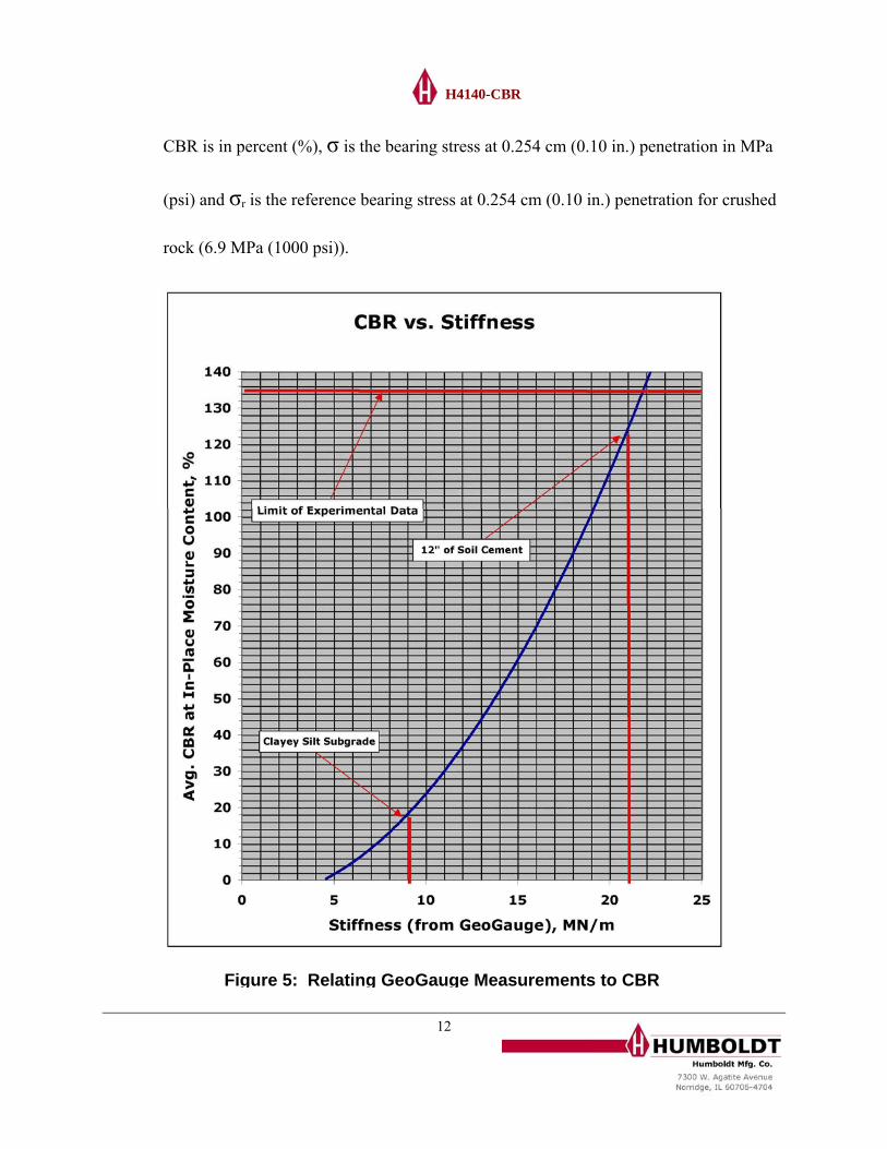
equation where CBR is in percent (%) and KG is the GeoGauge stiffness in MN/m (see
Figure 5). The correlation coefficient (R2) for all data fitted to this equation is 0.84.
samples made from grading spillage taken in the area of the GeoGauge measurements.2
at the in-
6.3 F
may be estimated from the GeoGauge measurements by using the following
CBR = 0.0039(8.672KG )2 − 5.75
6.2 This relationship was established by the Louisiana Department of Transportation &
Development by correlating GeoGauge measurements made on fully prepared
(compacted) sites to unsoaked CBR measurements per ASTM D1883-99 on molded
CBR measurements were made at the in-place moisture content over a range of
compactive efforts so that GeoGauge and CBR measurements could be related
place density and moisture. The relationship represents cement & lime treated soils,
unstablized cohesive soils, granular soils, crushed aggregate (limestone) and recycled
asphalt pavement.
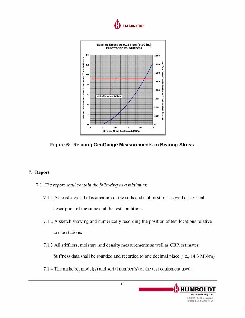
igure 6 is the same relationship placed in terms of bearing stress. This relationship
assumes that CBR and bearing stress are related as follows (ref. ASTM D1883-99).
CBR =σσ r
⎛
⎝ ⎜
⎞
⎠ •100 ⎟
11
H4140-CBR
CBR is in percent (%), σ is the bearing stress at 0.254 cm (0.10 in.) penetration in MPa
(psi) and σr is the reference bearing stress at 0.254 cm (0.10 in.) penetration for crushed
rock (6.9 MPa (1000 psi)).
Figure 5: Relating GeoGauge Measurements to CBR12
H4140-CBR
T
7.1
7.1
7.1
7. Repor
7.1
7.1
Figure 6: Relating GeoGauge Measurements to Bearing Stress
he report shall contain the following as a minimum:
.1 At least a visual classification of the soils and soil mixtures as well as a visual
description of the same and the test conditions.
.2 A sketch showing and numerically recording the position of test locations rela
to site stations.
.3 All stiffness, moisture and density measurements as well as CBR estimates.
Stiffness data shall be rounded and recorded to one decimal place (i.e., 14
t
tive
.3 MN/m).
.4 Th ed. e make(s), model(s) and serial number(s) of the test equipment us
13

H4140-CBR
14
7.1.5 The name
7.1.6
8. Precision and Bias
8.1 Precision
8.1.1 In this me ation of a set of
repeated me
(s) of the operator(s).
Identification of the project, the site and test locations.
thod, precision is defined as the coefficient of vari
asurements as follows:
100*S
P σ=
P = instrument precision in %
where:
S = the average stiffness of measurements made at one test location, MN/m (klbf/in)
= one standard deviation of the stiffness
t per this method is represented
Gauge and three operators on the
8.1.3 f any given measurement depends on the surface conditions of the
8.2 Bias
σ
8.1.2 Typically, the precision of a stiffness measuremen
by a coefficient of variation of less than approximately 8.5 %. This value
represents repeated measurements for three Geo
same location.3
The precision o
layer being measured and how well the foot of the GeoGauge is seated.

H4140-CBR
8.2.1 The stiffness reference for this test method is a moving mass as defined in Section
8.2.2 The bias of a stiffness measurement per this method is a coefficient of variation of
6.
≤1%.
1 Nelson, C. R. ldt GeoGauge With In-Place Quasi-Static Plate Load Tests, December, 1999, CNA Consulting Engineers, Minneapolis, MN 55414 2 Murad Y. Abu-Farsakh, Ph.D., P.E., Khalid Alshibli, Ph.D., P.E, Munir Nazzal, and Ekrem Seyman, Assessment Of In-Situ Test Technology FTransportation Research Center, Baton Rouge, LA 70808, FHWA/LA.04/385 3 Test Report FHWA GeoGauge Study SPR-2(212) Validation Of Seating Procedure & Demonstration Of Precision, Octo Humboldt Mfg. Co. for Florida Department Of Transportation, State Materials Office, Gainesville, FL 326& Test Report FH ird Validation Of Seating Procedure & Demonstration Of Precision, JanuaryGeotechnical S regate Branch, Materials and Pavements Section, Austin, TX 78717
and Sondag, M., Comparison of the Humbo
or Construction Control Of Base Courses And Embankments, May, 2004, Louisiana
ber, 2002,09
WA GeoGauge Study SPR-2(212) Th, 2003, Humboldt Mfg. Co. for Texas Department Of Transportation Construction Div.,
oils and Agg
15