Standard Phased Array Probes and Accessories · · 2017-11-02More information on our full range...
52
GE Measurement & Control Standard Phased Array Probes and Accessories www.UTprobes.com
Transcript of Standard Phased Array Probes and Accessories · · 2017-11-02More information on our full range...

GEMeasurement & Control
Standard Phased Array Probes and Accessorieswww.UTprobes.com

2
Table of contents
Introduction ............................................................................................................................................3
Definitions ...............................................................................................................................................4
Connector Options ...................................................................................................... 5
General Use Probes ............................................................................................................................6
Wedges-Delay Lines-Wear Caps for General Use Probes ................................................7
Corrosion Probes .................................................................................................................................8
Accessories for Corrosion Probes .................................................................................................9
MSWS Probes ...................................................................................................................................... 10
Wedges for MSWS Probes ............................................................................................................. 11
Scribeline Probes .............................................................................................................................. 12
Wedges for Scribeline Probes ...................................................................................................... 13
Hardwater Probes ............................................................................................................................ 14
Accessories for Hardwater Probes ............................................................................................ 15
Immersion Probes ............................................................................................................................ 16
High Resolution Probes................................................................................................................... 17
RotoArray ............................................................................................................................................. 18
Accessories for RotoArray Probes ............................................................................................. 19
Integral Wedge Probes .................................................................................................................. 20
Certificates of Conformity ............................................................................................................ 21
Regional Offices ................................................................................................................................ 28

3
GE’s Inspection Technologies business manufactures a wide variety of phased arraytransducers for use with Phasor XS and other ultrasonic flaw detectors.
33 standard phased array transducers cover a broad application spectrum and are stocked and available with short delivery times. All these probes offer three connector options and are manufactured to GE’s high quality standards.
More information on our full range of phased array transducers is available atwww.UTprobes.com

4
Definitions
1. KERF: Spacing between elements.
2. PITCH: Element size plus kerf.
3. PASSIVE WIDTH / Elevation: Size of element on linear array in non steering axis.
4. LINEAR ARRAY: Array with the ability to steer in one axis and fixed on the opposite axis or scan in one axis.
5. TEST MATERIAL: The common name of the material being tested (ex. carbon steel).
6. ACOUSTIC VELOCITY: The wave speed of the desired wave mode in the material (preferred units = inches x 106 per second). Please specify the acoustic velocity if it is known. Otherwise, GE will use the general published velocity for the material.
7. COUPLANT MEDIUM: What couplant material will be used between the probe and the test specimen (wedge, water, coolant, etc… also include wedge thickness or water patch used).
8. VIRTUAL PROBE: Size of the element when fired (example: linear array 1 mm pitch x 10 mm width fired with 10 elements would have a virtual probe size of 10 mm x 10 mm). Note: Array near field and focus ability will be determined by the Virtual Probe size used during the test.
9. LINE FOCUS: Array will focus in a line (flat linear array when focused at a certain depth will give a line focus, similar to a cylindrical focus single element probe).
10. SPOT FOCUS: Array will focus at a point.
1.75D Array 2D ArrayLinear Array
A
APassiveWidth
Pitch
Pitch ShortAxis
Pitch LongAxis A
Pitch Long Axis
Pitch Short Axis
Passive
Linear Array
5
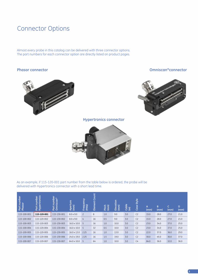
As an example, if 115-120-001 part number from the table below is ordered, the probe will be delivered with Hypertronics connector with a short lead time.
Phasor connector
Hypertronics connector
Omniscan®connector
Almost every probe in this catalog can be delivered with three connector options. The part numbers for each connector option are directly listed on product pages.
Connector Options
Part
num
ber
Phas
or
Part
num
ber
H
yper
tron
ics
Part
num
ber
O
mni
scan
®
Aper
ture
(mm
)
Freq
uenc
y(M
Hz)
Elem
ent C
ount
Pitc
h
(mm
)
Elev
atio
n (m
m)
Cabl
e(m
)
Case
Sty
le
A (mm)
B (mm)
C (mm)
D (mm)
115-100-001 115-120-001 115-130-001 8.0 x 9.0 2 8 1.0 9.0 3.0 C2 15.0 28.0 27.0 21.0
115-100-002 115-120-002 115-130-002 8.0 x 9.0 4 16 0.5 9.0 3.0 C2 15.0 28.0 27.0 21.0
115-100-003 115-120-003 115-130-003 16.0 x 10.0 5 16 1.0 10.0 3.0 C2 23.0 34.0 37.0 25.0
115-100-004 115-120-004 115-130-004 16.0 x 10.0 5 32 0.5 10.0 3.0 C2 23.0 34.0 37.0 25.0
115-100-005 115-120-005 115-130-005 16.0 x 13.0 2.25 16 1.0 13.0 3.0 C2 22.0 37.0 36.0 29.0
115-100-006 115-120-006 115-130-006 24.0 x 19.0 2.25 16 1.5 19.0 3.0 C2 30.0 45.0 30.0 37.0
115-100-007 115-120-007 115-130-007 64.0 x 10.0 5 64 1.0 10.0 3.0 C4 84.0 36.0 32.0 36.0

6
General Use Probes
Applications• General weld inspection• Tubes, pipes, tanks, pressure vessels• Axles, forgings, castings• Bridges and other structures• Railroad wheels and rail• Pumps, valve housings• Turbine blades, shafts• Wheel rims
Features• Wide range of applications• 3 different connector types available• Used with wedges, delay lines, or wear caps• Used for sector scanning or linear scanning
B
DC
A
F
AB
E
C
D
C2 C4
Part
num
ber
Phas
or
Part
num
ber
H
yper
tron
ics
Part
num
ber
O
mni
scan
®
Aper
ture
(mm
)
Freq
uenc
y(M
Hz)
Elem
ent C
ount
Pitc
h
(mm
)
Elev
atio
n (m
m)
Cabl
e(m
)
Case
Sty
le
A (mm)
B (mm)
C (mm)
D (mm)
E (mm)
F (mm)
115-100-001 115-120-001 115-130-001 8.0 x 9.0 2 8 1.0 9.0 3.0 C2 15.0 28.0 27.0 21.0 - -
115-100-002 115-120-002 115-130-002 8.0 x 9.0 4 16 0.5 9.0 3.0 C2 15.0 28.0 27.0 21.0 - -
115-100-003 115-120-003 115-130-003 16.0 x 10.0 5 16 1.0 10.0 3.0 C2 23.0 34.0 37.0 25.0 - -
115-100-004 115-120-004 115-130-004 16.0 x 10.0 5 32 0.5 10.0 3.0 C2 23.0 34.0 37.0 25.0 - -
115-100-005 115-120-005 115-130-005 16.0 x 13.0 2.25 16 1.0 13.0 3.0 C2 22.0 37.0 36.0 29.0 - -
115-100-006 115-120-006 115-130-006 24.0 x 19.0 2.25 16 1.5 19.0 3.0 C2 30.0 45.0 30.0 37.0 - -
115-100-007 115-120-007 115-130-007 64.0 x 10.0 5 64 1.0 10.0 3.0 C4 84.0 36.0 32.0 36.0 71.0 28.0

7
Wedges/Delay Lines/Wear Caps for General Use Probes
Features
• Sectorial scanning• Small footprint design• Curved wedges available• Optional carbide and couplant ports
Accessories Part numbersPart number Phasor
Part number Hypertronics
Part number Omniscan®
Shear Wedge35° to 75°
Delay Line20 mm (0.79”)
Delay Line40 mm (1.58”)
Wear Cap
115-100-001 115-120-001 115-130-001 118-350-024 118-350-036 118-350-048 118-240-003
115-100-002 115-120-002 115-130-002 118-350-024 118-350-036 118-350-048 118-240-003
115-100-003 115-120-003 115-130-003 118-350-025 118-350-037 118-350-049 118-240-004
115-100-004 115-120-004 115-130-004 118-350-025 118-350-037 118-350-049 118-240-004
115-100-005 115-120-005 115-130-005 118-350-027 118-350-039 118-350-063 118-240-001
115-100-006 115-120-006 115-130-006 118-350-028 118-350-040 118-350-064 118-240-002
115-100-007 115-120-007 115-130-007 360-141-182 (sweep angle) 118-350-026 (fixed angle, lateral sweep)
118-350-038 118-350-050 118-240-005
StandardWedges
C(mm)
D (mm)
E (mm)
F (mm)
Incident Z-Offset * (mm)
WF *(mm)
118-350-024 28.2 24.7 15.0 12.3 36 10.6 18.7
118-350-025 33.5 32.6 18.5 21.3 36 12.4 24.1
118-350-026 84.0 54.8 31.1 84.1 36 20.6 40.5
360-141-182 35.6 124.5 59.9 35.6 36 35.3 65.8
118-350-027 37.3 37.8 22.9 22.0 36 15.9 28.9
118-350-028 45.4 50.0 29.6 26.4 36 20.5 37.4
StandardDelay Lines
C(mm)
D (mm)
E (mm)
118-350-036 28.2 15.0 20.0
118-350-037 33.5 23.0 20.0
118-350-038 84.0 35.6 20.0
118-350-039 37.3 21.0 20.0
118-350-063 37.3 21.0 40.0
118-350-040 45.4 30.0 20.0
118-350-064 45.4 30.0 40.0
StandardDelay Lines
C(mm)
D (mm)
E (mm)
118-350-048 28.2 15.0 40.0
118-350-049 33.5 23.0 40.0
118-350-050 84.0 35.6 40.0
E
C
D
C
E
DF
* Z-Offset is the dimension from the center of the array mounted on the wedge to the bottom of the wedge (perpendicular to the bottom). This value is used to calculate delay laws in the Phasor.
* WF (Wedge Front) is the dimension from the center of the array mounted on the wedge to the front of the wedge. This value is entered into the Phasor and directly affect the frame of reference from which all projection results are measured.
Standard wedge
Delay line

8
Corrosion Probes
Applications• Remaining wall thickness, corrosion, erosion• Near surface flaw detection• Bond testing
Features• Amazing near surface resolution; 1.9 mm (0.075“)
on a #4 flat bottomed hole (1.5 mm / 0.062“ diameter)• Optimum test range 1.9 mm (0.075“) to 25.4 mm (1“)
in steel• Adjustable wear bars• Available with 3 different connectors
EF C
AD
B
Part
num
ber
Phas
or
Part
num
ber
H
yper
tron
ics
Part
num
ber
O
mni
scan
®
Aper
ture
(mm
)
Freq
uenc
y
(MH
z)
Elem
ent C
ount
Pitc
h
(mm
)
Elev
atio
n
(mm
)
Cabl
e
(m) A
(mm)B(mm)
C(mm)
D(mm)
E(mm)
F
115-100-020 115-120-020 115-130-020 48.0 x 10.0
5 Dual 32
1.5 5.0 3.0 9.1 25.4 65.5 24.4 16.0
M3X
0.5
115-100-021 115-120-021 115-130-021 24.0 x 10.0
5 Dual 32
0.8 5.0 3.0 9.1 25.4 41.0 24.4 16.0
M3X
0.5

9
Accessories for Corrosion Probes
Features• Curved wear bars for alignment on curved pipe• Flat wear bars for durability on flat plate• Potted wear bars for flat or curved bars with fittings for couplant feed
Flat Wear Bars Mate
389-075-530 115-100-020, 115-120-020, 115-130-020
389-075-540 115-100-021, 115-120-021, 115-130-021
Curved Wear Bars Mate
389-075-560 115-100-020, 115-120-020, 115-130-020
389-075-570 115-100-021, 115-120-021, 115-130-021
Curved Ported Wear Bars Mate
389-077-160 115-100-020, 115-120-020, 115-130-020
389-077-150 115-100-021, 115-120-021, 115-130-021
Flat Ported Wear Bars Mate
389-076-700 115-100-020, 115-120-020, 115-130-020
389-077-140 115-100-021, 115-120-021, 115-130-021
Curved wear bars Curved wear bars
Flat ported wear bars
Long flat wear bars
Curved ported wear bars

10
MSWS 2MSWS 1
MSWS Probes
Applications• General weld inspection, smaller objects, thinner
sections• Tubes, pipes, pressure vessels, containers• Pumps, vlalve housings• Turbine blades, shafts• Wheel rims
Features• Small contact area• Fits on standard single element MSWS wedges• Comparable to standard single element MSWS probes
with Phased Array capabilities• Available with 3 different connectors
Part
num
ber
Phas
or
Part
num
ber
H
yper
tron
ics
Part
num
ber
O
mni
scan
®
Aper
ture
(mm
)
Freq
uenc
y
(MH
z)
Elem
ent C
ount
Pitc
h
(mm
)
Elev
atio
n
(mm
)
Cabl
e
(m)
Case
Sty
le
A(mm)
B(mm)
C(mm)
D(mm)
E
115-100-010 115-120-010 115-130-010 12.8 x 12.7 5 32 0.4 12.7 3 MSWS1 19.1 15.1 16.3 16.0 #1-64
115-100-011 115-120-011 115-130-011 12.8 x 12.7 10 32 0.4 12.7 3 MSWS1 19.1 15.1 16.3 16.0 #1-64
115-100-015 115-120-015 115-130-015 6.35 x 6.35 10 16 0.4 6.35 3 MSWS2 9.5 12.6 11.2 9.5 #1-64
115-100-012 115-120-012 115-130-012 12.8 x 12.7 5 16 0.8 12.7 3 MSWS1 19.1 15.1 16.3 16.0 #1-64
115-100-013 115-120-013 115-130-013 12.8 x 12.7 2.25 16 0.8 12.7 3 MSWS1 19.1 15.1 16.3 16.0 #1-64
115-100-037 115-120-037 115-130-037 6.4 x 6.4 5 16 0.4 6.4 3 MSWS2 9.5 12.6 11.2 9.5 #1-64
E
C
A
D
B B
C
A
D
E

11
WI W2 W3
Wedges for MSWS Probes
Features• Delay line or wedge attachment• Small contact area • Custom wedge angles and curvatures can be special ordered• Manual or automated inspections
Mates to Case style
Wedge Style Order Code Shear Wave Carbon Steel
A (mm)
B (mm)
C (mm)
D (mm)
MSWS2 W1 360-141-219 30-80 DG 22.9 16.8 12.9 -
MSWS2 W2 118-340-028 45 DG 15.2 12.7 6.7 -
MSWS2 W2 118-340-030 60 DG 16.6 12.7 7.6 -
MSWS2 W2 118-340-032 70 DG 18.5 12.7 8.2 -
MSWS2 W2 118-340-034 80 DG 20.2 12.7 8.5 -
MSWS2 W3 118-340-036 90 DG 15.2 12.7 8.6 17.4
MSWS1 W2 118-340-040 45 DG 23.9 19.1 10.9 -
MSWS1 W2 118-340-042 60 DG 26.7 19.1 12.6 -
MSWS1 W2 118-340-044 70 DG 29.8 19.1 13.5 -
MSWS1 W2 118-340-046 80 DG 32.4 19.1 14.0 -
MSWS1 W3 118-340-048 90 DG 26.3 19.1 14.8 30.2
C
BA
C
A B
C
D
A B
12
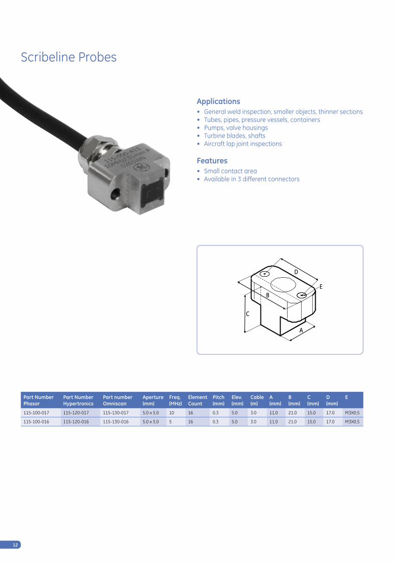
Scribeline Probes
Applications• General weld inspection, smaller objects, thinner sections• Tubes, pipes, pressure vessels, containers• Pumps, valve housings• Turbine blades, shafts• Aircraft lap joint inspections
Features• Small contact area• Available in 3 different connectors
A
C
D
BE
Part Number Phasor
Part Number Hypertronics
Part number Omniscan
Aperture(mm)
Freq.(MHz)
Element Count
Pitch(mm)
Elev.(mm)
Cable (m)
A (mm)
B (mm)
C (mm)
D (mm)
E
115-100-017 115-120-017 115-130-017 5.0 x 5.0 10 16 0.3 5.0 3.0 11.0 21.0 15.0 17.0 M3X0.5
115-100-016 115-120-016 115-130-016 5.0 x 5.0 5 16 0.3 5.0 3.0 11.0 21.0 15.0 17.0 M3X0.5

13
Wedges/Delay line for Scribeline Probes
Features• Delay line and wedge attachment• Small contact area • Custom wedge angles and curvatures can be special ordered• Manual or automated inspections
Order Code Wedge A (mm) B (mm) C (mm)
360-141-129 W4 17.8 21.3 11.6
360-141-148 W4 20.8 21.3 10.2
Order Code Delay line A (mm) B (mm) C (mm)
389-081-360 D1 12.7 25.4 19.9
389-071-220 D1 12.7 25.4 10.0
C
A B
D1 W4
A B
C

14
Hardwater Probes
Applications• Composite inspection• Bubbler applications where water is an issue
Features• Probes use hardwater delay* to minimize water required
for coupling• Delay acoustically matched to water to minimize the
water to delay interface• Available with 3 different connectors
C
B
A
Part number Phasor
Part number Hypertronics
Part number Omniscan
Aperture (mm)
Freq. (MHz)
Element Count
Pitch (mm)
Elev.(mm)
Cable(mm)
A(mm)
B(mm)
C(mm)
115-100-027 115-120-027 115-130-027 40.6 x 8.0 5 32 1.3 8.0 6.0 13.0 43.0 31.0
115-100-028 115-120-028 115-130-028 81.2 x 8.0 5 64 1.3 8.0 6.0 13.0 86.0 31.0
A(mm)
*Hardwater delay is a material applied to the face of the probe that is non-removable.
Main benefits:Accoustically matches water to minimize interface echo.Improves near surface resolution.Decreases operating gain and frequency. (5MHz design frequency operates at approximately 2.6MHz)

15
Accessories for Hardwater Probes
Features• Bubbler fixture for automated or hand scanning• Available with or without encoder• Applies 0.050” water coupling to hardwater probe
C
BA
Part Number Waterbox Description Mating Probe A (mm) B (mm) C (mm)
022-509-571 WB1 Waterbox with side mount encoder module Hardwater Probe,
115-100-028, 115-120-028, 115-130-028
48.0 106.0 31.0
389-064-070 WB2 Waterbox, no encoder48.0 125.0 31.0
389-074-200 WB2 Waterbox with mini encoder
WB1 WB2
C
BA

16
Immersion Probes
Applications• Composite plate inspection• Immersion scanning area coverage• Plates, billets and bars• Disks, axles and shafts• Large area scanning
Features• Acoustically matched for best efficiency in water• Fixture mountable• Fast inspection of large areas• Waterproof design• Near wall design allows close access to edge of case (~1 mm)• 6 meter cable
C
B
A
Part
num
ber
Phas
or
Part
num
ber
H
yper
tron
ics
Part
num
ber
O
mni
scan
®
Aper
ture
(mm
)
Freq
uenc
y
(MH
z)
Elem
ent C
ount
Pitc
h
(mm
)
Elev
atio
n
(mm
)
Cabl
e
(m) Ca
se S
tyle
A (mm)
B (mm)
C (mm)
115-100-035 115-120-035 115-130-035 64.0 x 7.0 3.5 64 1.0 7.0 6.0 INW2 19.0 65.9 22.0
115-100-036 115-120-036 115-130-036 64.0 x 7.0 5 64 1.0 7.0 6.0 INW2 19.0 65.9 22.0
N/A 115-120-031 115-130-031 76.8 x 10.0 5 128 0.6 10.0 6.0 IM2 21.0 83.0 35.0
N/A 115-120-032 115-130-032 64.0 x 7.0 10 128 0.5 7.0 6.0 IM2 21.0 83.0 35.0
N/A 115-120-033 115-130-033 96.0 x 12.0 2.25 128 0.8 12.0 6.0 IM3 21.0 102.0 35.0
N/A 115-120-034 115-130-034 96.0 x 10.0 5 128 0.8 10.0 6.0 IM3 21.0 102.0 35.0
C
B
A
IM2 & IM3 INW2

17
High Resolution Probes
Typical Applications•ThinPlate,nearsurfacedefects,smalldefects
Advantages• High frequency highly damped arrays for near
surface inspections• Acoustically matched to water/delay material• Waterproof design
Part
num
ber
Phas
or
Part
num
ber
H
yper
tron
ics
Part
num
ber
O
mni
scan
®
Aper
ture
(mm
)
Freq
uenc
y(M
Hz)
Elem
ent C
ount
Pitc
h
(mm
)
Elev
atio
n (m
m)
Cabl
e(m
)
Case
Sty
le
A (mm)
B (mm)
C (mm)
D (mm)
E
115-100-025 115-120-025 115-130-025 16.0 x 10.0 10 32 0.5 10.0 3.0 HRD1 23.8 38.5 12.7 32.2 M3X.5
115-100-026 115-120-026 115-130-026 32.0 x 10.0 10 64 0.5 10.0 3.0 HRD1 23.8 54.5 12.7 48.2 M3X.5
Removable Delay Line (included with transducer)
Transducer number
387-007-296 (12.7 mm length) 115-100-025, 115-120-025, 115-130-025
387-007-295 (12.7 mm length) 115-100-026, 115-120-026, 115-130-026
C
D
AB

18
RotoArray
Applications• Primarily for the inspection of composite
materials and structures• Flaw detection and thickness measurement
in a wide range of materials• Inspection during manufacture as well as for
in service inspection
Features• Excellent acoustic performance• Use in any attitude including overhead• Transparent tire for easy bubble removal• Unique encoder• 3 popular connector options• Owner serviceable• Platform for future models • Interactive digital manual on UTprobes.com
Standard 0-59 mm width arrayThe compact 51.2 mm RotoArray is designed for quick and easy scanning of a variety of different applications. Its small design allows it to be used in tight locations and its light weight and egronomic design keeps the operator from becoming fatigued during long periods of use.
Standard 60-99 mm width arrayThe 81.3 mm RotoArray is currently our only standard offering in the 60-99 mm range. Its larger size makes it ideal for inspecting airframes and fuselages.
Part
num
ber
Phas
or
Part
num
ber
H
yper
tron
ics
Part
num
ber
O
mni
scan
®
Cove
rage
are
a (m
m)
Freq
uenc
y(M
Hz)
Pitc
h
(mm
)
Elem
ents
Elev
atio
n (m
m)
Focu
s
Cabl
e(m
)
Prob
e O
ffse
t (m
m)
115-910-100 115-920-100 115-930-100 51.2 5 0.8 64 6.4 Flat 3.0 28.2
Part
num
ber
Phas
or
Part
num
ber
H
yper
tron
ics
Part
num
ber
O
mni
scan
®
Cove
rage
are
a (m
m)
Freq
uenc
y(M
Hz)
Pitc
h
(mm
)
Elem
ents
Elev
atio
n (m
m)
Focu
s
Cabl
e(m
)
Prob
e O
ffse
t (m
m)
115-910-200 115-920-200 115-930-200 81.3 5 1.3 64 8.0 Flat 3.0 28.2

19
Accessories for RotoArray
The accessories included with the RotoArray allow for full functionality, and help to keep it maintained and functioning.
The optional accessories are highly recommended for the RotoArray and provide an ease of maintenance, verification, and use.The comprehensive RotoArray Service Station is one of the most useful accessories allowing users to minimize downtime by carrying out any necessary repairs and maintenance on a customized workbench fitted with all the necessary tools.
Incl
uded
/ O
ptio
nal
Acce
ssor
ies
Part
Num
bers
115-
910-
100
115-
920-
100
115-
930-
100
115-
910-
200
115-
920-
200
115-
930-
200
Encoder 3 meter cable to 7 pin Lemo Included (if Yes) 388-000-506 YES YES YES YES YES YES
Frame Assembly w/ handels Included (if Yes) YES YES YES YES YES YES
3 switch assembly w/ 3meter lemo Included (if Yes) 388-000-500 NO YES YES NO YES YES
Fluid fill bottle assembly Included (if Yes) 389-079-240 YES YES YES YES YES YES
Couplant Spray bottle Included (if Yes) 021-265-015 YES YES YES YES YES YES
Propylene Glycol 1Qt Included (if Yes) 111-200-559 YES YES YES YES YES YES
RotoArray tool kit Included (if Yes) 388-000-502 YES YES YES YES YES YES
RotoArray spare parts kit Included (if Yes) 388-000-503 YES YES YES YES YES YES
Case Included (optional large or small)
Small= 021-026-099Large= 021-026-354
Small or large
Small or large
Small or large
Small or large
Small or large
Small or large
Adapter Cable Included (if Yes) (optional DBHD or Fisher)
DBHD= 388-000-501Fisher= 388-000-525
NO DBHD-15 or Fisher
DBHD-15 or Fisher
NO DBHD-15 or Fisher
DBHD-15 or Fisher
Tire Change Station Optional 389-079-390 Optional Optional Optional Optional Optional Optional
Egronomic Water Sprayer Optional 021-265-020 Optional Optional Optional Optional Optional Optional
Demo Block Kit Optional 389-081-400 Optional Optional Optional Optional Optional Optional
Included Accessories
Optional Accessories

20
Integral Wedge Probes
Applications• General weld inspection: MWB for small parts, SWB for
thick parts• Other applications where conventional MWB or SWB
probes are in use
Features• Easy transfer from conventional to phased array
inspection• Durable and ergonomically-designed, die-cast housing
as known from conventional probes• Existing mechanics and probe holders can be re-used• Non-detachable wedges, no coupling loss between
probe and wedge• Replacement soles (sold separately) for extended
service life
DB
A
C
Part
num
ber
Phas
or
Part
num
ber
H
yper
tron
ics
Part
num
ber
O
mni
scan
®
Prob
e
Des
crip
tion
Aper
ture
(mm
)
Freq
uenc
y
(MH
z)
Elem
ent C
ount
Pitc
h
(mm
)
Elev
atio
n
(mm
)
Cabl
e
(m)
Case
Sty
le
A(mm)
B(mm)
C(mm)
D(mm)
69141 69732 69730 MWB2PA16 8.0 x 9.0 2 16 0.5 9.0 2.0 MWB 14.0 24.0 22.0 2.0
69142 69733 69731 MWB4PA16 8.0 x 9.0 4 16 0.5 9.0 2.0 MWB 14.0 24.0 22.0 2.0
Part
num
ber
Phas
or
Part
num
ber
H
yper
tron
ics
Part
num
ber
O
mni
scan
®
Prob
e
Des
crip
tion
Aper
ture
(mm
)
Freq
uenc
y
(MH
z)
Elem
ent C
ount
Pitc
h
(mm
)
Elev
atio
n
(mm
)
Cabl
e
(m)
Case
Sty
le
A(mm)
B(mm)
C(mm)
D(mm)
69143 69738 69736 SWB2PA16 14.0 x 14.0 2 16 0.9 14.0 2.0 SWB 22.0 37.0 31.0 3.0
69144 69739 69737 SWB4PA16 14.0 x 14.0 4 16 0.9 14.0 2.0 SWB 22.0 37.0 31.0 3.0

21
GEMeasurement & Control
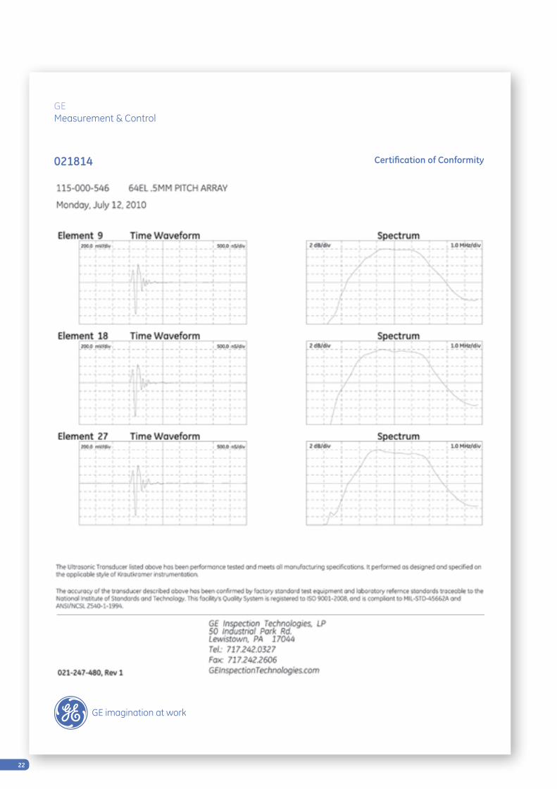
Certification of Conformity021814
22
GEMeasurement & Control
Certification of Conformity021814

23
GEMeasurement & Control
Certification of Conformity021814

24
GEMeasurement & Control
Certification of Conformity021814

25
GEMeasurement & Control
Certification of Conformity021814

26
GEMeasurement & Control
Certification of Conformity021814

27
Integral Wedge Probes Certificate

© 2012 General Electric Company. All Rights Reserved. Specifications are subject to change without notice. GE is a registered trademark of General Electric Company. Other company or product names
mentioned in this document may be trademarks or registered trademarks of their respective companies, which are not affiliated with GE.
GEIT-20122
Regional Offices
Europe Americas AsiaGermanyRobert Bosch Strasse 3 50354 Huerth
+49 2233 6010
Lotzenäcker Strasse 4 72379 Hechingen (RVI only)
+49 (0) 7471 9882 0
Niels-Bohr-Strasse 7 31515 Wunstorf P.O. Box 6241 (RT only)
31510 Wunstorf +49 5031 172 0 Bogenstrasse 41 22926 Ahrensburg (RT only)
+49 4102 807 117
United Kingdom892 Charter Avenue Canley Coventry CV4 8AF
+44 845 130 3925
France68, Chemin des Ormeaux Limonest 69760
+33 47 217 9220
SpainSan Maximo, 31, Planta 4A, Nave 6 Madrid 28041
+34 915 500 59 90
United States50 Industrial Park Road Lewistown, PA 17044
+1 866 243 2638 (toll free) +1 717 242 0327
721 Visions Drive Skaneateles, NY 13152 (RVI only)
+1 888 332 3848 (toll free) +1 315 554 2000 ext. 1
BrazilAv. das Nacoes Unidas, 8501 1st floor São Paulo, SP 05425-070
Tel: + 55 3067 8166
China5F, Building 1, No.1 Huatuo Road, Zhangjiang High-Tech Park, Shanghai 201203
+86 800 915 9966 (toll-free) +86 (0) 21-3877 7888
Unit 1602, 16/F Sing Pao Building 101 King’s Road North Point Hong Kong
+852 2877 0801
Japan7F Medie Corp Bldg. 8 2-4-14 Kichijoji Honcho, Musashino-shi Tokyo 180-0004
+81 442 67 7067
GE Sensing & Inspection Technologies has sales and service offices all over the world. Below are some of our locations. Visit www.geit.com for a complete listing.
• Berchem,Belgium
• Alzenau,Germany
• Burford,UnitedKingdom
• Moscow,Russia
• Bucharest,Romania
• Prague,CzechRepublic
• Stockholm,Sweden
• Milan,Italy
• EastPerth,Australia
• Singapore
• Dubai,UAE
• BuenosAires,Argentina
• MexicoCity,Mexico
• Airdrie,Alberta,Canada
• Toronto,Ontario,Canda
• Montreal,Quebec,Canada
www.UTprobes.com

GE Measurement & Control
Wear Resistant, Straight Beam, Phased Array Probes With DGS Functionality
Realise the benefits of DGS sizing with just one straight beam probeThe DGS method is specified in many countries worldwide as a sentencing technique for sizing defects. When using conventional straight beam probes, obtaining a comprehensive coverage involves using wedges to provide various angles of inspection, a method which requires calibration for each angle which is usually only carried out on a specific number of angles.
The new B.SPA16 probe is a phased array probe, where the longitudinal wave sound beam is electronically steered through a sector of up to +/-30°, producing inspection data in one degree steps. The patented design transducer is compatible with the specific software in GE’s Phasor XS allowing it to perform accurate DGS sizing of a detected flaw at each angle.
The sector scanning of the new probes can reduce inspection times to 1/16 of those required using conventional scanning at eight discrete angles.
Sizing made easy There are just three steps to a sizing inspection using the B.SPA16 probe: Calibrate – Detect – Read
One Probe – Sector Scan – Simple CalibrationCombining the Advantages of Conventional B.S and Phased Array ProbesAccurate Detection and Sizing of Defects Over a Steering Range of up to +/-30°
The first phased array straight beam contact probe which offers ergonomic inspection to find and size defects over a steering range of up to +/-30°. The new probe, which features a non-abrasive, probe surface protection membrane, provides faster, more accurate and more comprehensive inspection in applications where conventional straight beam probes have historically been used in conjunction with wedges, leading to significantly increased productivity and probability of detection.
When used with GE’s Phasor XS, a single probe allows accurate DGS sizing of defects in thick components from billets, large welds, castings and forgings to solid axles and threaded bolts over the complete steering range.
The replaceable non-abrasive protective, ES45-type membrane provides a long probe lifetime and a reliable coupling on rough surfaces. In combination with the ergonomic housing design of all B.S probes, these probes offer ease of inspection, even for extensive inspection tasks.
B.SPA16 Probes
www.ge-mcs.com
© 2014 General Electric Company. All Rights Reserved. Specifications are subject to change without notice. GE is a registered trademark of General
Electric Company.
Features Benefits
1. Accurate DGS sizing in a straight beam contact probe. 1. Provides the benefits of DGS sizing in a single probe, reducing inspection times, compared with DAC inspection, and improving accuracy.
2. Can be used as a standard Phased Array straight beam probe.
2. Can be used to carry out standard Phased Array probe operations, including thickness measurement, dynamic focusing and DAC sizing.
3. Replaceable probe face protection membrane. 3. Allows long working life.
4. Steerable phased array sound beam for comprehensive coverage over a sector scan of up to +/-30°.
4. Eliminates the need for multiple inspections using different wedges, as required with conventional straight beam probes. Saves time while providing more comprehensive inspection coverage.
5. High energy longitudinal wave. 5. Enables the inspection of thick parts and provides an easy-to-interpret sector scan.
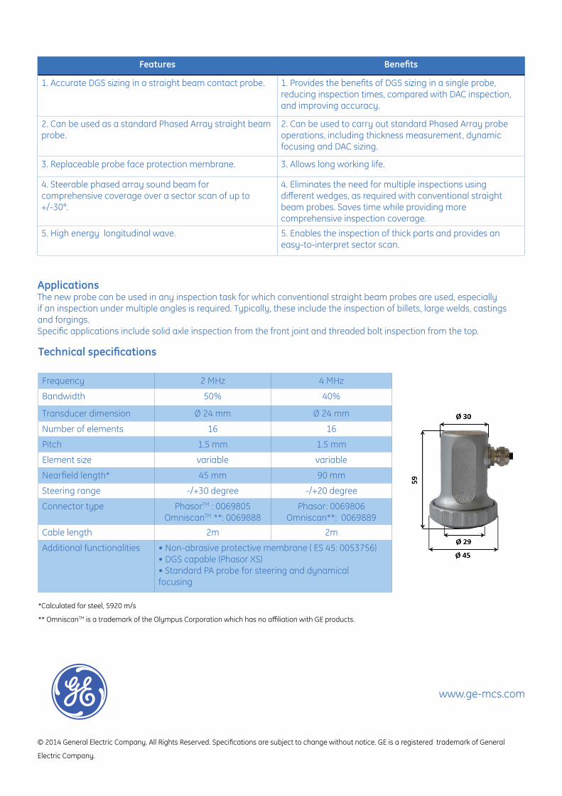
Applications The new probe can be used in any inspection task for which conventional straight beam probes are used, especially if an inspection under multiple angles is required. Typically, these include the inspection of billets, large welds, castings and forgings.Specific applications include solid axle inspection from the front joint and threaded bolt inspection from the top.
Technical specifications
Frequency 2 MHz 4 MHz
Bandwidth 50% 40%
Transducer dimension Ø 24 mm Ø 24 mm
Number of elements 16 16
Pitch 1.5 mm 1.5 mm
Element size variable variable
Nearfield length* 45 mm 90 mm
Steering range -/+30 degree -/+20 degree
Connector type PhasorTM : 0069805OmniscanTM **: 0069888
Phasor: 0069806Omniscan**: 0069889
Cable length 2m 2m
Additional functionalities • Non-abrasive protective membrane ( ES 45: 0053756)• DGS capable (Phasor XS)• Standard PA probe for steering and dynamical focusing
*Calculated for steel, 5920 m/s
** OmniscanTM is a trademark of the Olympus Corporation which has no affiliation with GE products.

GE Measurement & Control
DGS Sizing, Thickness Measurement and Near-Surface Flaw Detection With Just One Probe
The DGS method is specified in many countries worldwide as a sentencing technique for detecting and sizing defects. The method was originally developed for straight beam probes. However, to obtain comprehensive coverage, this involves using wedges to provide various angles of inspection, a method which requires calibration for each probe/wedge unit and which is usually only carried out at a specified number of angles.
The new MB.SPA16 probe is a phased array probe, where the longitudinal wave sound beam is electronically steered through a sector of up to +/- 35°, producing inspection data in one degree steps, without the need for wedges and individual wedge calibration. This sector scanning significantly reduces inspection times compared with those required using conventional scanning under multiple angles.
Straight Beam Phased Array Probes, Providing DGS Functionality Without Wedges, Significantly Reducing Inspection Times and Improving Productivity.
Detection of Defects over a Longitudinal Wave Steering Range of +/- 45°, andAccurate DGS Sizing of Defects over a Steering Range of +/- 35°.
The MB.SPA16 probe is a member of GE’s innovative family of phased array straight beam contact probes and allows accurate detection and sizing of flaws in welded joints, billet materials, medium castings and forgings with a typical inspection thickness range of 10 – 100mm.
Its contact surface offers a smaller footprint than other probes in the family, so that it maintains good coupling when inspecting curved surfaces.
It is a straight beam probe with a circular transducer that provides near-surface flaw detection and requires no wedges to carry out volumetric inspection. The patented DGS functionality of the transducer design is compatible with the specific software in GE’s Phasor XS providing compliant defect sizing over a steering of +/- 35°. The probe can also be used for standard phased array applications such as DAC sizing and thickness measurements and can be used with other commercial flaw detectors.
It features a replaceable, non-abrasive membrane of type ES24 to protect the contact surface, so that the probe offers a long working lifetime with reliable coupling on rough inspection surfaces.
With the same ergonomic and robust housing as GE’s MB.S conventional probes, the new probe offers ease of inspection in the harshest of applications.
MB.SPA16 Probes

www.ge-mcs.com
Features Benefits
1. Accurate DGS sizing in a straight beam contact probe over a +/- 35° sector.
1. Provides the benefits of DGS sizing in a single probe for a steering range of +/- 35°, reducing inspection times, compared with DAC inspection, and improving accuracy.
2. Steerable phased array sound beam allows comprehensive coverage over a +/- 45° sector.
2. Eliminates the need for multiple inspections using different wedges, as required with conventional straight beam probes. Saves time while providing more comprehensive inspection coverage.
3. High energy longitudinal wave. 3. Can inspect parts of medium thickness, up to 100mm and provides an easy-to-interpret sector scan.
4. Replaceable probe face protection membrane. 4. Allows long working life
5. Can be used as standard phased array probe for straight beam applications.
5. Can be used to carry out standard phased array probe operations, including thickness measurement, dynamic focusing and DAC sizing.
6. Small footprint of probe contact surface. 6. Can be used on curved surfaces.7. A robust and ergonomic MB.S-type probe housing. 7. Easy to use in harsh environments.
Sizing Made EasyThere are just three steps to a sizing inspection using the MB.SPA16 probe: Calibrate – Detect – Read.
Applications
The MB.SPA16 probe will provide faster, more accurate and more comprehensive DGS inspection in applications where conventional straight beam probes have historically been used in conjunction with wedges. Typically, these include the inspection of billets, welds, castings, forgings and composites.
The probe can also be used as a conventional straight beam probe for thickness measurement, dynamic focusing and DAC sizing.
One single probe for a wide range of applications.
Technical specificationsFrequency 2 MHz 4 MHzBandwidth 50% 40%Transducer dimension Ø 10 mm Ø 10 mmNumber of elements 16 16Pitch 0.63 mm 0.63 mmElement size variable variableNear-field length* 8 mm 15.6 mmSteering range* -/+45 degree -/+45 degreeDGS Steering range* -/+35 degree -/+35 degreeConnector type PhasorTM : 0069905
OmniscanTM **: 0069907Phasor: 0069906
Omniscan**: 0069908Cable length 2m 2mAdditional functionalities • non-abrasive protective membrane ( ES 24 : 0053769)
• DGS capable (Phasor XSTM)• Standard PA probe for steering and dynamical focusing
*Calculated for steel, 5920 m/s
** OmniscanTM is a trademark of the Olympus Corporation which has no affiliation with GE products.

GE Measurement & Control
Increased Sensitivity, Near Surface Defect Detection with High Resolution and Comprehensive Inspection coverage With Just One Probe
Obtaining comprehensive inspection coverage with conventional probes involves using wedges to provide various angles of inspection, a method which requires calibration for each probe/wedge unit and which is usually only carried out at a specified number of angles. The use of wedges or delay lines limits the inspection range and reduces the inspection sensitivity resulting in a reduced probability of detection for small defects at large distances.
The new B.FPA16 probe is a phased array probe, where the longitudinal wave sound beam is electronically steered through a sector of up to +/- 35°, producing inspection data in one degree steps, without the need for wedges and individual wedge calibration. This sector scanning significantly reduces inspection times with respect to those required using conventional scanning under multiple angles. The full coverage of the sector scan and higher sensitivity of the probe increases the probability of detection even for small defects and large material thicknesses.
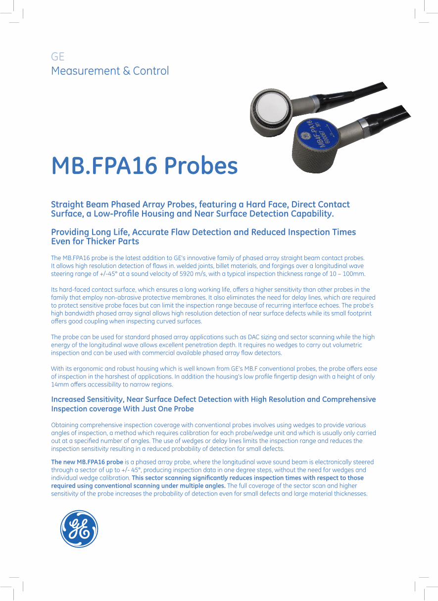
Straight Beam Phased Array Probes, featuring a Hard Face, Direct Contact Surface,a Low-Profile Housing and Near Surface Detection Capability.
Providing Long Life, Accurate Flaw Detection and Reduced Inspection Times Even for Thicker Parts.
The B.FPA16 probe is the latest addition to GE’s innovative family of phased array straight beam contact probes. It allows high resolution detection of flaws in welded joints, billet materials and forgings, over a longitudinal steering range of +/-35° at a sound velocity of 5920 m/s.
Its hard-faced contact surface, which ensures a long working life, offers a higher sensitivity than other probes in the family that employ non-abrasive protective membranes. It also eliminates the need for delay lines, which are required to protect sensitive probe faces but can limit the inspection range because of recurring interface echoes. The probe’s high bandwidth phased array signal allows high resolution detection of near surface defects.
The probe can be used for standard phased array applications such as DAC sizing and sector scanning, while the high energy of the longitudinal wave allows excellent inspection of thick parts. It requires no wedges to carry out volumetric inspection and can be used with commercial available phased array flaw detectors.
With its ergonomic and robust housing which is well known from GE’s B.F conventional probes, the probe offers ease of inspection in the harshest of applications. In addition the housing’s low profile fingertip design with a height of only 14mm offers accessibility to narrow regions.
B.FPA16 Probes

www.ge-mcs.com
GEIT-20128 EN (03/15)
Features Benefits
1. Steerable phased array sound beam allows comprehensive coverage over an up to +/- 35° sector.
1. Eliminates the need for multiple inspections using different wedges, as required with conventional straight beam probes. Saves time while providing more comprehensive inspection coverage
2. High energy steerable longitudinal wave. Coupling face best matched to metals.
2. Enables the inspection of thick parts and provides an easy-to-interpret sector scan. Higher sensitivity than other probes employing non-abrasive protective mem branes or delay lines.
3. High bandwidth signal. 3. High resolution of defects and near surface defect detection.
4. Hard-face contact surface for long durability, no need of delay lines which limit the inspection range
4. Allows long working life, inspection range not limited by recurring interface echoes.
5. A robust, small finger-tip and ergonomic B.F-type probe housing with a height of only 14mm.
5. Easy to use in harsh environments and provides accessibility of narrow regions.
Applications
The B.FPA16 probe will provide faster, more accurate and more comprehensive inspection in applications where conventional straight beam probes have historically been used in conjunction with wedges. Typically, these include the inspection of billets, welds and forgings. In addition the probe replaces standard phased array applications in which delay lines are used. Due to the low profile housing the probe can be used in applications with limited access space.
The probe can be used as a conventional straight beam probe for thickness measurement, dynamic focusing and DAC sizing.
One single probe for a wide range of applications.
Technical specifications
Frequency 2 MHz 4 MHzBandwidth > 40% > 60%Transducer dimension Ø 20 mm Ø 20 mmNumber of elements 16 16Pitch 1.25 mm 1.25 mmElement size variable variableNear-field length* 31 mm 62 mmSteering range* -/+35 degree -/+25 degreeConnector type PhasorTM : 0600064
OmniscanTM **: 0600068Hypertronics: 0600072
PhasorTM : 0600065OmniscanTM**: 0600069Hypertronics: 0600073
Cable length 2m / 3m / 3m 2m / 3m / 3mAdditional functionalities • Hard-face contact surface
• Near surface resolution• Low Profile Housing• Standard PA probe for steering and DAC sizing
*Calculated for steel, 5920 m/s
** OmniscanTM is a trademark of the Olympus Corporation which has no affiliation with GE products.
GE Measurement & Control
Increased Sensitivity, Near Surface Defect Detection with High Resolution and Comprehensive Inspection coverage With Just One Probe
Obtaining comprehensive inspection coverage with conventional probes involves using wedges to provide various angles of inspection, a method which requires calibration for each probe/wedge unit and which is usually only carried out at a specified number of angles. The use of wedges or delay lines limits the inspection range and reduces the inspection sensitivity resulting in a reduced probability of detection for small defects.
The new MB.FPA16 probe is a phased array probe, where the longitudinal wave sound beam is electronically steered through a sector of up to +/- 45°, producing inspection data in one degree steps, without the need for wedges and individual wedge calibration. This sector scanning significantly reduces inspection times with respect to those required using conventional scanning under multiple angles. The full coverage of the sector scan and higher sensitivity of the probe increases the probability of detection even for small defects and large material thicknesses.
Straight Beam Phased Array Probes, featuring a Hard Face, Direct Contact Surface, a Low-Profile Housing and Near Surface Detection Capability.
Providing Long Life, Accurate Flaw Detection and Reduced Inspection Times Even for Thicker Parts
The MB.FPA16 probe is the latest addition to GE’s innovative family of phased array straight beam contact probes. It allows high resolution detection of flaws in. welded joints, billet materials, and forgings over a longitudinal wave steering range of +/-45° at a sound velocity of 5920 m/s, with a typical inspection thickness range of 10 – 100mm.
Its hard-faced contact surface, which ensures a long working life, offers a higher sensitivity than other probes in the family that employ non-abrasive protective membranes. It also eliminates the need for delay lines, which are required to protect sensitive probe faces but can limit the inspection range because of recurring interface echoes. The probe’s high bandwidth phased array signal allows high resolution detection of near surface defects while its small footprint offers good coupling when inspecting curved surfaces.
The probe can be used for standard phased array applications such as DAC sizing and sector scanning while the high energy of the longitudinal wave allows excellent penetration depth. It requires no wedges to carry out volumetric inspection and can be used with commercial available phased array flaw detectors.
With its ergonomic and robust housing which is well known from GE’s MB.F conventional probes, the probe offers ease of inspection in the harshest of applications. In addition the housing’s low profile fingertip design with a height of only 14mm offers accessibility to narrow regions.
MB.FPA16 Probes

www.ge-mcs.com
GEIT-20127 EN (03/15)
Features Benefits
1. Steerable phased array sound beam allows comprehensive coverage over a +/- 45° sector
1. Eliminates the need for multiple inspections using different wedges, as required with conventional straight beam probes. Saves time while providing more comprehensive inspection coverage.
2. High energy steerable longitudinal wave. Coupling face best matched to metals.
2. Can inspect parts of medium thickness, up to 100mm and provides an easy-to-interpret sector scan. Higher sensitivity than other probes employing non-abrasive protective membranes or delay lines.
3. High bandwidth signal. 3. High resolution of defects and near surface defect detection.
4. Hard-face contact surface for long durability, no need of delay lines which limit the inspection range
4. Allows long working life, inspection range not limited by recurring interface echoes.
5. Small footprint of probe contact surface 5. Can be used on curved surfaces
6. A robust, small finger-tip and ergonomic MB.F-type probe housing with a height of only 14mm.
6. Easy to use in harsh environments and provides accessibility of narrow regions
Applications
The MB.FPA16 probe will provide faster, more accurate and more comprehensive inspection in applications where conventional straight beam probes have historically been used in conjunction with wedges. Typically, these include the inspection of billets, welds and forgings. In addition the probe replaces standard phased array applications in which delay lines are used. Due to the low profile housing the probe can be used in applications with limited access space.
The probe can be used as a conventional straight beam probe for thickness measurement, dynamic focusing and DAC sizing.
One single probe for a wide range of applications.
Technical specificationsFrequency 2 MHz 4 MHzBandwidth >40% >60%Transducer dimension Ø 10 mm Ø 10 mmNumber of elements 16 16Pitch 0.63 mm 0.63 mmElement size variable variableNear-field length* 8 mm 15.6 mmSteering range* -/+45 degree -/+45 degreeConnector type PhasorTM : 0600066
OmniscanTM **: 0600070Hypertronics: 0600074
PhasorTM: 0600067OmniscanTM**: 0600071Hypertronics: 0600075
Cable length 2m / 3m / 3m 2m / 3m / 3mAdditional functionalities • Hard-face contact surface
• Near surface resolution• Low Profile Housing• Standard PA probe for steering and DAC sizing
*Calculated for steel, 5920 m/s
** OmniscanTM is a trademark of the Olympus Corporation which has no affiliation with GE products.

GEInspection Technologies Ultrasonics
Digital | Eddy Current | Film | Testing Machines | Ultrasonics | X-ray
Linear Phased Array Probes for Angle Beam Inspection with Replaceable Wedges
What is a Phased Array Probe?A phased array probe can be compared to a large single element transducer whose active area has been sub- divided into small segments or elements. When connected to appropriate instrumentation, the beam from the phased
array is steered and focused electronically by sequentially firing the elements of the array. Angle and focal depth are generated electronically by the instrumentation and can be changed on each pulse repetition.
All electronically controlled
• Variable virtual probe size (aperture)
• Variable beam angle
• Variable focal depth
• Beam indexing (scanning) for large area coverage
• Low noise wedge design
• Standard Hypertronics connector
Key Features
Advantages of Angle Beam Phased Array Probes • Eliminate multiple inspections with fixed angle probes.
• Increase sensitivity and signal to noise ratio with electronic focusing.
• Inspect hard to access areas from a single contact point.
• High sensitivity, broadband piezocomposite elements
• Reduce mechanical and manual manipulation.
• Probes may also be used for immersion and water column testing.
• Replaceable wedges maximize service life of the array probe.
• Replaceable wedges enable a broad range of applications for each probe.

GEInspectionTechnologies.com
Standard Probe Configurations (custom designs also available)
Product Code Frequency Element Pitch Aperture Dimensions (mm)(MHz) Count (mm) (Active Area) A B C D
115-000-235115-000-234115-000-189115-000-190
1.52.255.07.5
32323232
1110,5
32 x 10 mm32 x 10 mm32 x 10 mm16 x 10 mm
16.516.516.516.5
45.645.645.631.8
25.425.425.425.4
38.138.138.122.9
Delay Lines and Wedges – Product Codes
Probe Delay Line, Wedge, 30° to 70° Wedge, 30° to 70°Product Code 0° Shear Wave Longitudinal Wave
115-000-235 (Footprint115-000-234 (Footprint)115-000-189 (Footprint)115-000-190 (Footprint
360-141-002 (50.8 x 35.6 mm)360-141-002 (50.8 x 35.6 mm)360-141-002 (50.8 x 35.6 mm)360-141-003 (31.8 x 35.6 mm)
360-141-027 (54.6 x 16.5 mm)360-141-027 (54.6 x 16.5 mm)360-141-027 (54.6 x 16.5 mm)360-141-050 (47.0 x 16.5 mm)
360-141-046 (50.8 x 16.5 mm)360-141-046 (50.8 x 16.5 mm)360-141-046 (50.8 x 16.5 mm)360-141-079 (31.1 x 16.5 mm)
NOTE: Angles specified are for carbon steel.
• Weld inspection, manual or automated
• Immersion testing with variable focus and beam angle
• Flaw detection and sizing in tubular goods, castings, forgings, axles, shafts, et al
• Pressure vessels and piping
• Turbine blades, rotor discs, et al
Typical Applications
Power Generation
Oil and Gas
Transportation
Aerospace
Major Industry Segments Served
© 2005 General Electric Company. All Rights Reserved. GEIT-20113US (04/05) We reserve the right to technical modifications without prior notice.

GEInspection Technologies Ultrasonics
Digital | Eddy Current | Film | Testing Machines | Ultrasonics | X-ray
• Variable virtual probe size (aperture)
• Variable beam angle
• Variable focal depth
• Beam indexing (scanning) for large area coverage
• Low noise wedge design
• Standard Hypertronics connector
Angle Beam Phased Array Probes Linear 19 mm x 12 mm with Replaceable Wedges
What is a Phased Array Probe?A phased array probe can be compared to a large single element transducer whose active area has been sub- divided into small segments or elements. When connected to appropriate instrumentation, the beam from the phased
array is steered and focused electronically by sequen-tially firing the elements of the array. Angle and focal depth are generated electronically by the instrumentation and can be changed on each pulse repetition.
• Significantly reduce setup time.
• Significantly reduce scan time.
• Eliminate multiple inspections with fixed angle probes.
• Increase sensitivity and signal to noise ratio with elec-tronic focusing.
• Inspect hard to access areas from a single contact point.
• High sensitivity, broadband piezocomposite elements
• Reduce mechanical and manual manipulation.
• Probes may also be used for immersion and water col-umn testing.
• Replaceable wedges maximize service life of the array probe.
• Replaceable wedges enable a broad range of applica-tions for each probe.
Advantages of Angle Beam Phased Array Probes
Key Features
All electronically controlled

GEInspectionTechnologies.com ©2005 General Electric Company. All Rights Reserved. GEIT-20115GB (07/05)We reserve the right to technical modifications without prior notice.
Typical Applications • Weld inspection, manual or automated
• Flaw detection and sizing in tubular goods, castings, forgings, axles, shafts, et al
• Pressure vessels and piping
• Turbine blades, rotor discs, nozzles, et al
• Pipeline girth welds
• Aircraft landing gear
• Bridges and structures
Power Generation
Oil and Gas
Transportation
Aerospace
Major Industry Segments Served
Standard Wedges (special configurations and curvatures available on request)Product Code Nominal Refracted Angle Incident Angle Footprint (mm) Height (mm)
360-141-043 50° L-wave 18° 16.5 x 37.2 15.5
360-141-044 50° Shear-wave 35° 16.5 x 49.5 22.9
NOTE: Angles specified are for carbon steel
Standard Probe Configurations - Linear (custom designs also available)
Product Code Frequency Element Pitch Aperture Dimensions (mm)(MHz) Count (mm) (Active Area) A B C D
115-000-262115-000-263115-000-264115-000-311
2.25 5.0 7.510.0
32323232
0.60.60.60.6
19 mm 12 mm19 mm 12 mm19 mm 12 mm19 mm 12 mm
16.516.516.516.5
45.645.645.645.6
25.425.425.425.4
38.138.138.138.1

GEInspection Technologies Ultrasonics
Digital | Eddy Current | Film | Testing Machines | Ultrasonics | X-ray
All electronically controlled
2D Dual Phased Array for Angle Beam Inspection of Coarse Grain Materials with Replaceable Wedge
• Variable beam size or aperture
• Variable refracted angle
• Variable roof angle and focus
• Low noise wedge design
• Standard Hypertronics connector
Key Features
Advantages of 2D Dual Angle Beam Phased Array • Dual, transmit/receive design improves signal to noise
ratio in coarse grain materials.
• 4 x 7 element matrix on both transmit and receive sides enables variable refracted angle and variable “roof angle” to control effective focal depth.
• Used as transmit/receive pair for dual operation.
• Each half can also be used as single array probe in pulse-echo mode.
• Eliminate multiple inspections with fixed angle probes.
• Increase sensitivity and signal to noise ratio with electronic focusing.
• Inspect hard to access areas from a single contact point.
• High sensitivity, broadband piezocomposite elements
• Reduce mechanical and manual manipulation.
• Replaceable wedges maximize service life of the array probe.
• Replaceable wedges enable a broad range of applications.
What is a Phased Array Probe?A phased array probe can be compared to a large single element transducer whose active area has been sub- divided into small segments or elements. When connected to appropriate instrumentation, the beam from the phased
array is steered and focused electronically by sequentially firing the elements of the array. Angle and focal depth are generated electronically by the instrumentation and can be changed on each pulse repetition.

GEInspectionTechnologies.com
• Detection and sizing of IGSCC
• Angle beam inspection of most coarse grain metals.
• General weld inspection, manual or automated
Typical Applications
Power Generation
Oil and Gas
Major Industry Segments Served
Specifications (Left and Right pair required for dual operation)
Product Code Frequency Element Pitch Active Area Dimensions (mm)(MHz) Count (mm) (mm) A B C D
115-000-089 (left)115-000-090 (right)
1.51.5
28 (7 x 4)28 (7 x 4)
2.7 x 3.02.7 x 3.0
19 x 1219 x 12
16.416.4
33.833.8
19.119.1
28.728.7
Wedges (other configurations available on request)
Product Code Dual/ Nominal Refracted Incident Roof Footprint Height CurvatureSingle Angle Angle Angle (mm) (mm) (mm)
118-340-360118-340-401118-340-403118-340-431118-340-406118-340-374
118-340-361118-340-434118-340-400118-340-402118-340-430118-340-373
360-141-043360-141-044
DualDualDualDualDualDual
DualDualDualDualDualDual
SingleSingle
50° L-wave50° L-wave50° L-wave50° L-wave50° L-wave50° L-wave
50° Shear-wave50° Shear-wave50° Shear-wave50° Shear-wave50° Shear-wave50° Shear-wave
50° L-wave50° Shear-wave
18°18°18°18°18°18°
35°35°35°35°35°35°
18°35°
5°17°13°13° 4° 5°
6.5°14°24°15°14° 6.5°
NoneNone
34.2 x 32.639.7 x 34.040.4 x 33.535.9 x 33.137.1 x 35.334.2 x 32.6
34.2 x 39.340.2 x 40.938.0 x 39.540.0 x 38.540.2 x 40.934.2 x 39.3
16.5 x 37.216.5 x 49.5
19.530.128.221.120.619.5
23.930.942.139.730.923.9
15.522.9
Flat114 OD, axial propagation
168 OD, axial propagation
273 OD, axial propagation
324 OD, axial propagation
508 OD, axial propagation
FlatFlat114 OD, axial propagation
168 OD, axial propagation
273 OD, axial propagation
508 OD, axial propagation
FlatFlat
NOTE: Angles specified are for carbon steel
© 2005 General Electric Company. All Rights Reserved. GEIT-20112US (04/05) We reserve the right to technical modifications without prior notice.

GEInspection Technologies Ultrasonics
Digital | Eddy Current | Film | Testing Machines | Ultrasonics | X-ray
• Variable beam size or aperture, controlled electronically
• Variable spherical (point) focus, controlled electronically
• Replaceable center element to optimize near surface resolution
• Three connections to center element (see figures page 2) - UHF on probe head, Lemo 00 on Hypertronics connector, and Hypertronics pin G-19
• 4.5 m shielded cable standard
Annular Phased Array Probes for Multi-zone Immersion Inspection
What is a Phased Array Probe?A phased array probe can be compared to a large single element transducer whose active area has been sub- divided into small segments or elements. When connected to appropriate instrumentation, the beam from an annular
phased array is focused electronically by sequentially firing the elements of the array. Focal depth is generated electronically by the instrumentation and can be changed on each pulse repetition.
• Eliminate multiple inspections with fixed focus probes.
• Change focal depth electronically with each pulse of the instrument.
• Increase sensitivity and signal to noise ratio with electronic focusing.
• Eliminate costly set up time required with multiple fixed focus probes.
• High sensitivity, broadband piezocomposite elements
• Annular rings have equal area for best element uniformity.
• High resolution design, 7.5 MHz and 10 MHz frequencies
Advantages of Annular Phased Arrays
Key Features

GEInspectionTechnologies.com ©2005 General Electric Company. All Rights Reserved. GEIT-20114US (04/05)We reserve the right to technical modifications without prior notice.
Typical Applications • Multi-zone immersion testing of billet, bar and rod.
• Focused immersion inspection of tubular goods.
• Focused immersion inspection of forgings and shafts.
• General immersion tests currently performed with focused probes.
Aerospace
Oil and Gas
Power Generation
Transportation
Major Industry Segments Served
Annular Phased Array Probe ConfigurationUHF-Connector Center Element LEMO-Connector Center Element
Specifications
Product Code Frequenzcy (MHz)
Element Count
Pitch (mm)
Total Active Diameter
Typical Bandwidt
115-000-256115-000-064
7.510.0
1616
See table belowSee table below
31.831.8
> 70%> 70%
Annular Element ConfigurationElement Iside Radius (mm) Outside Radius (mm)
1 2 3 4 5 6 7 8 910111213141516
6.0 7.0 7.9 8.7 9.510.210.911.512.112.813.313.914.515.015.5
5.8 6.8 7.7 8.5 9.310.010.711.311.912.613.113.714.314.815.315.9
39.8 mm
37.3 mm
UHV Connector Center Element
LEMO Connector Center Element

GEMeasurement & Control
PALM ScannerWeld assessment of difficult-to-access, small diameter pipes

PALM Scanner
NDT inspections of circumferential butt welds are a complex task. This type of joint is found in various structures including small diameter tubes in boilers. Experts inspect these to find defects which could result in the failure of a component, possibly inducing a human or environmental hazard.
Four factors define the quality of these inspections:• Safety • Inspection duration • Measurement precision and reliability • Quality data management
Operating Information
The PALM Scanner family inspects pipes of diameters from 1.5” up to 3.5”. The tools are adaptable with various wedges and phased array probes to suit any inspection procedures regardless of tube thickness, material or acceptance criteria.
The PALM Scanners are delivered with a wide selection of accessories in order to make inspection and/or equipment handling even simpler.
Outline
• Compact, rigid and lightweight• Easy access between gaps as narrow
as 12 mm• Optimum spring-loaded open clamp
system• No axial slip• Excellent UT signal• Reliable measurements• Fast and easy translations between
measurements• Suitable for ferromagnetic and
non-ferromagnetic pipes• Adapts to various probes and wedges• Provides optimum circumferential weld
measurement for each tube size• Operated by a single person• Easy to set up• Parallel mounting for inspection from
both sides• CE compliant (waterproof and rust-free)
Product Offering
PALM 50 Scanner (1.5” – 2.0” diameter tube) 0600140
PALM 64 Scanner (2.0” – 2.5” diameter tube) 0600141
PALM 90 Scanner (2.5” – 3.5” diameter tube) 0600142
PALM 50 Double-sided Extension 0161925
PALM 64 Double-sided Extension 0161926
PALM 90 Double-sided Extension 0161927 PALM Scanner with double-sided extension
13,0
21,8
21,99616,5
M2,5x45
M2x4
25,4
13,3
9,7
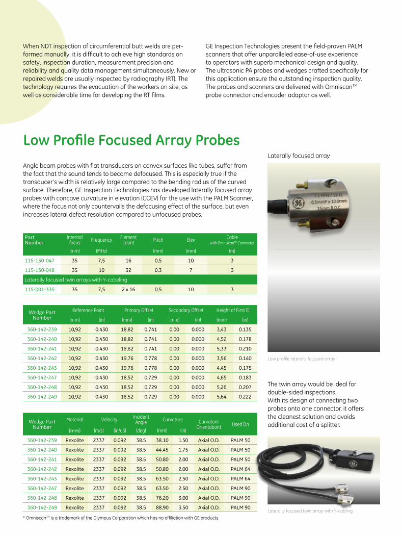
Low Profile Focused Array ProbesAngle beam probes with flat transducers on convex surfaces like tubes, suffer from the fact that the sound tends to become defocused. This is especially true if the transducer’s width is relatively large compared to the bending radius of the curved surface. Therefore, GE Inspection Technologies has developed laterally focused array probes with concave curvature in elevation (CCEV) for the use with the PALM Scanner, where the focus not only countervails the defocusing effect of the surface, but even increases lateral defect resolution compared to unfocused probes.
When NDT inspection of circumferential butt welds are per-formed manually, it is difficult to achieve high standards on safety, inspection duration, measurement precision and reliability and quality data management simultaneously. New or repaired welds are usually inspected by radiography (RT). The technology requires the evacuation of the workers on site, as well as considerable time for developing the RT films.
GE Inspection Technologies present the field-proven PALM scanners that offer unparalleled ease-of-use experience to operators with superb mechanical design and quality. The ultrasonic PA probes and wedges crafted specifically for this application ensure the outstanding inspection quality. The probes and scanners are delivered with OmniscanTM probe connector and encoder adaptor as well.
Part Number
Internalfocus Frequency Element
count Pitch Elev Cable with OmniscanTM Connector
(mm) (MHz) (mm) (mm) (m)
115-130-047 35 7,5 16 0,5 10 3
115-130-048 35 10 32 0.3 7 3
Laterally focused twin arrays with Y-cabeling
115-001-335 35 7,5 2 x 16 0,5 10 3
Wedge Part Number
Reference Point Primary Offset Secondary Offset Height of First El.
(mm) (in) (mm) (in) (mm) (in) (mm) (in)
360-142-239 10,92 0.430 18,82 0.741 0,00 0.000 3,43 0.135
360-142-240 10,92 0.430 18,82 0.741 0,00 0.000 4,52 0.178
360-142-241 10,92 0.430 18,82 0.741 0,00 0.000 5,33 0.210
360-142-242 10,92 0.430 19,76 0.778 0,00 0.000 3,56 0.140
360-142-243 10,92 0.430 19,76 0.778 0,00 0.000 4,45 0.175
360-142-247 10,92 0.430 18,52 0.729 0,00 0.000 4,65 0.183
360-142-248 10,92 0.430 18,52 0.729 0,00 0.000 5,26 0.207
360-142-249 10,92 0.430 18,52 0.729 0,00 0.000 5,64 0.222
Wedge Part Number
Material Velocity Incident Angle Curvature Curvature
Orientationt Used On(mm) (m/s) (in/uS) (deg) (mm) (in)
360-142-239 Rexolite 2337 0.092 38.5 38.10 1.50 Axial O.D. PALM 50
360-142-240 Rexolite 2337 0.092 38.5 44.45 1.75 Axial O.D. PALM 50
360-142-241 Rexolite 2337 0.092 38.5 50.80 2.00 Axial O.D. PALM 50
360-142-242 Rexolite 2337 0.092 38.5 50.80 2.00 Axial O.D. PALM 64
360-142-243 Rexolite 2337 0.092 38.5 63.50 2.50 Axial O.D. PALM 64
360-142-247 Rexolite 2337 0.092 38.5 63.50 2.50 Axial O.D. PALM 90
360-142-248 Rexolite 2337 0.092 38.5 76.20 3.00 Axial O.D. PALM 90
360-142-249 Rexolite 2337 0.092 38.5 88.90 3.50 Axial O.D. PALM 90
The twin array would be ideal for double-sided inspections. With its design of connecting two probes onto one connector, it offers the cleanest solution and avoids additional cost of a splitter.
Laterally focused array
Low profile laterally focused array
Laterally focused twin array with Y-cabling
* OmniscanTM is a trademark of the Olympus Corporation which has no affiliation with GE products

GE Business Unit, LLC is a subsidiary of the General Electric Company. The GE brand, logo, and Lumination are trademarks of the GeneralElectric Company. © 2015 GE Business Unit, LLC. The USG brand & Logix are trademarks of USG Interiors, LLC. Information provided is subjectto change without notice. All values are design or typical values when measured under laboratory conditions.
GEIT-20071EN (10/15)
www.gemeasurement.comImagination at work
Angle beam probes with flat transducers on convex surfaces like tubes, suffer from the fact, that the sound tends to become defocused because of refraction at the interface between wedge and specimen. This is especially true if the transducer’s width is relatively large compared to the bending radius of the curved surface (Fig. 1).
One application where this scenario becomes necessary to understand is the testing of welds of thin walled boiler tubes. This tubes normally have diameters in the range of 1,5 to 3,5 inch and wall-thicknesses of only a couple of millimeter. Flaws that normally have to be characterized in these welds are also only couple of millimeters in width and thus comparable to the width of the sound-field of commonly used probes (Fig. 1).
Since -6dB drop-down is the most prevalent sizing technique flaws will always be characterized larger than they are because the operator detects the overlap of sound-field and flaw. Thus, GE Sensing & Inspection Technologies’ new low-profile phased array probe for testing small diameter tubes have concavely curved transducers to reduce the width of the sound-field in the region of flaws of typical components. With curved transducers the width of the sound-field can be reduced significantly (Fig.2).
Although pictures show sound-pressure distributions of conventional single element probes, the same applies for phased array probes.
Fig.1: Qualitative comparison of sound-fields after 1st skip of 45° transversal wave angle beam conventional probes. Both specimen had a thickness of 10 mm with flat geometry (left) and R=25 mm curvature (right).Pictures show sound pressure distribution perpendicularly to the acoustical axis.
Fig.2: Qualitative comparison of sound-fields after 1st skip of 45° transversal wave angle beam conventional probes. Both transducers have the same width of 10 mm, whereas one is flat (left) and the other is concavely curved (right).Pictures show sound pressure distribution perpendicularly to the acoustical axis.
Scanner Packages
PALM 50 package (PALM 50, 7,5 MHz Probe, 3 x Wedges, Safety Case, Encoder Adapter) 0600143
PALM 64 package (PALM 64, 7,5 MHz Probe, 2 x Wedges, Safety Case, Encoder Adapter) 0600144
PALM 90 package (PALM 90, 7,5 MHz Probe, 3 x Wedges, Safety Case, Encoder Adapter) 0600145
Please note that double-side scanner extension is not included in packages and has to be ordered separately.
All wedges are compatible to the low profile probes in this brochure. They are designed with integrated irrigation channels and all the curvatures are crafted to fit the PALM scanner seamlessly.
Complete set of tools you need for the inspection is delivered in one package. The scanner pack ages include a PALM scanner, a 7.5 MHz laterally focused array probe with OmniscanTM connector, three wedges, an encoder adapter to OmniscanTM and all the equip-ment is packed in a safety case.”
Wedges Scanner Packages
Why laterally focused arrays for small diameter tube inspection?
Low profile probe with wedge
PALM Scanner in a safety case

GEMeasurement & Control
PALM Flat Scannerfor general weld inspection

Features
• Compact, rigid, lightweight and robust (IP67, stainless)
• Low profile to pass clearances as low as 30 mm (1.2”) dependent on probe
• Reproducible adjustment of the probe position based on an integrated ruler
• Adaptive to various probes and wedges• Integrated robust encoder, which can
easily be replaced by the operator• Spring-loading and gimbaling of probes• Magnetic wheels to stick to tube and for
straight guiding• Manual brake for hand-free locking at any
position• Easy switching from axial to
circumferential direction and back• Operatable by a single person• Easy to set up• CE compliant
PALM Flat Scanner
Weld inspections are crucial during themanufacturing process, as well as on a regular basis to ensure weld integrity. Inspections with conventional ultrasonic angle beam probes are time consuming and provide limited
documentation. Probability of detection is reduced due to the limited amount of angles used, which could result in missed indications. GE Inspection Technologies now offers the PALM Flat Scanner to perform more accurate and efficient weldinspections.
Encoded Phased-Array inspection of welds offers the benefits of a reduced inspection time, while increasing the probability of detection and providing a comprehensive documentation of the inspection results directly on the instrument. The PALM Flat Scanner is a versatile and ergonomic inspection tool featuring an integrated encoder and magnetic wheels, allowing vertical and overhead operation. The scanner can be used on diameters larger than 90 mm for circumferential scanning and 200 mm for axial scanning.
Operating Information
The PALM Flat Scanner– part of the PALM Scanner family - circumferentially inspects pipes of diameters from 90 mm (3.5”) outer diameter to flat and inner diameters down to 250 mm (10”), The minimum diameter of axial scanning is 200 mm. The tools can carry probes upto the size of 70 mm (length) x 50 mm (width) to suit any inspection procedure regardless of tube thickness, material or acceptance criteria.
The PALM Flat Scanner is delivered with a wide selection of accessories in order to make inspection and/or equipment handling even simpler. With other types of probes, the PALM Flat Scanner has the potential to solve many other applications as well. Our solution teams in USA and Europe would be pleased to assist you with special application requests.

C-scan of weld displaying indications as high reflection signals (red and yellow amplitudes). The weld geometry is displayed in the C-Scan for localization. Cursors are available after the scan for determining the position of indications with respect to the weld geometry.
B-scan of weld displaying the depths of indications. The double V weld geometry of a 25 mm thick part is shown. Indications are detected between 1st and 2nd skip in the upper part of the weld at a depth of about 10 mm.
UT Scanning Results
Phased Array Probes
Part Number Connector type Frequency
(MHz) Element Pitch (mm)
Aperture (mm)
Elevation (mm)
115-100-001 Tyco (USM Vision+; Phasor) 2 8 1 8x9 9
115-100-002 Tyco (USM Vision+; Phasor) 4 16 0.5 8x9 9
115-130-001 IPEX (Omniscan)* 2 8 1 8x9 9
115-130-002 IPEX (Omniscan)* 4 16 0.5 8x9 9
Inspection of welds with a typical material thickness of up to 25 mm 15 mm
21 mm
28 mm
27 mm
Part Number
0600218 NPA36°M (flat)
0600183 NPA36°M R. (A-D)**
Wedges
Instrument specific wedge parameters for 0600218 and 0600183 type „A“ and „B“
16 mm
23 mm28 mm
Instrument Material Soundvelocity Incident Angle(deg)
PrimaryOffset
Hight of Reference Element
(m/s) (in/us) (mm) (in) (mm) (in)
Phasor/USM Vision+ Polystyrol 2380 0.0937 36 17 0.669 10.5 0.413
Omniscan* Polystyrol 2380 0.0937 36 20 0.787 8.3 0.327
** How to order custom wedge curvatures (see back page)

GE Business Unit, LLC is a subsidiary of the General Electric Company. The GE brand, logo, and Lumination are trademarks of the GeneralElectric Company. © 2015 GE Business Unit, LLC. The USG brand & Logix are trademarks of USG Interiors, LLC. Information provided is subjectto change without notice. All values are design or typical values when measured under laboratory conditions.
GEIT-20076EN (04/16)
www.gemeasurement.comImagination at work
High Frequency Focused Phased Array Probes
Part Number Connector type Frequency
(MHz) Element Pitch (mm)
Aperture (mm)
Elevation (mm)
Internal Focus (mm)
115-100-047 Tyco (USM Vision+; Phasor) 7.5 16 0.5 8x10 10 35
115-100-048 Tyco (USM Vision+; Phasor) 10 16 0.4 6.5x7 7 35
115-130-047 IPEX (Omniscan)* 7.5 16 0.5 8x10 10 35
115-130-048 IPEX (Omniscan)* 10 32 0.3 9x7 7 35
Inspection of welds with thin material thickness less than 8 mm
Wedges
0600219 NPA38°M (flat)
0600220 NPA38°M R.. (A-D)**
Instrument Material Soundvelocity Incident Angle(deg)
Primary Offset Hight of Reference Element
(m/s) (in/us) (mm) (in) (mm) (in)
Phasor/USM Vision+ Rexolite 2337 0.092 38.5 15.6 0.614 7.6 0.299
Omniscan* Rexolite 2337 0.092 38.5 18.52 0.729 5.27 0.207
16 mm
22 mm30 mm
Scanner PackagesScanner Packages
PALM Flat Scanner with Case 0600176
Encoder Adapter Phasor 0600185
Encoder Adapter MX1 0600135
Encoder Adapter MX2 0600136
When placing the order use the curvature specification and radius of the curvature to specify the wedge.Example: ordering 0600183 NPA36°M R.. (A-D) in curvature geometry “A” with 60 mm radius.
Use the following identifier when ordering0600183 NPA36°M R60 A
** How to order custom wedge curvatures
Applies only to part numbers 0600183 and 0600220 Choose letter specifying the curvature geometry according to below pictures
* Omniscan is a trademark of Olympus
Instrument specific wedge parameters for 0600219 and 0600220 type ‘A’ and ‘B’