Title: YALE OFFICE OF FACILITIES PROCEDURE MANUAL Section ...

Version 1.51, December 2020
Standard Operating Procedure I: XPS Spectral Measurement
Yale West Campus Materials Characterization Core ywcmatsci.yale.edu
ESC II, Room A119E 810 West Campus Drive West Haven, CT 06516

PHI 5000 VersaProbe II XPS
2
Yale West Campus Materials Characterization Core

PHI 5000 VersaProbe II XPS
3
Yale West Campus Materials Characterization Core
> FOLLOW the SOP strictly to keep the instrument in good condition. No
explorations allowed on software unless permitted by lab manager
> NEVER use your own USB drive on the XPS computer. Data can be either
uploaded to Yale Box, or copied to the Jump Drive provided by the Core.
> NEVER surf the web on the XPS computer to minimize the risk of the
computer being hacked
> Users should acknowledge MCC in their publications. Please check the
following link for details:
http://ywcmatsci.yale.edu/publications
> The core reserves the right to use the data for core promotion

PHI 5000 VersaProbe II XPS
4
Yale West Campus Materials Characterization Core

PHI 5000 VersaProbe II XPS
5
Yale West Campus Materials Characterization Core
Table of Contents 1 Introduction ............................................................................................................................. 1
2 Initial System Status Check .................................................................................................... 2
3 Sample Preparation ................................................................................................................. 3
3.1 Sample preparation in user lab ......................................................................................... 3
3.2 Sample holder types ......................................................................................................... 3
3.3 Sample mounting.............................................................................................................. 5
4 XPS Computer Login .............................................................................................................. 6
5 Create Sample in SmartSoft Program ..................................................................................... 7
6 Sample Loading into Intro Chamber....................................................................................... 8
7 Sample Transfer into Main Chamber .................................................................................... 14
8 XPS Scan .............................................................................................................................. 19
8.1 Stage Z-Alignment ......................................................................................................... 19
8.2 Create multiple sample positions ................................................................................... 20
8.3 XPS Survey (Full Range) Scan ...................................................................................... 21
8.4 Regional (Elemental) Scan ............................................................................................. 25
9 Closing XPS Measurement ................................................................................................... 28
10 Some Analysis Concepts....................................................................................................... 33
11 Chamber Leaking Emergency Operation Procedure ............................................................ 34

PHI 5000 VersaProbe II XPS
6
Yale West Campus Materials Characterization Core

PHI 5000 VersaProbe II XPS
1
Yale West Campus Materials Characterization Core
PHI 5000 VersaProbe II XPS/UP S Standard Operating Procedure (Basic XPS Measurement)
1 Introduction 1) Instrument Features:
> Micro-area element composition and chemical state determination on material surfaces > Analysis of insulating samples with dual beam charge neutralization method > Depth profile analysis of structures and interfaces
2) Location
Materials Characterization Core Room A119E 810 West Campus Dr West Haven, CT 06516
3) Primary Staff Contact
Min Li, director Tel: 203-737-8270 Email: [email protected] Office: ESC II, Room E119E
Zishan Wu, lab assistant [email protected] 203-824-5563 (cell) Office: ESC II
Yiren Zhong, lab assistant [email protected] 203-710-9820 (cell)
The Yale West Campus MCC Facilities are operated for the benefit of all researchers. If you encounter any problems with this facility, please contact the staff member listed above immediately. There is never a penalty for asking questions. If the equipment is not behaving exactly the way it should, contact a staff member.
Notice: Please follow strictly the SOP to keep the facility under good condition. No explorations on program allowed unless approved by core manager.

PHI 5000 VersaProbe II XPS
2
Yale West Campus Materials Characterization Core
2 Initial System Status Check Warning: Before sample preparation and loading, the users are required to check the XPS system status following the steps listed below:
1) Check on the highlighted panel on the XPS control rack and make sure the main chamber pressure is below 5x10⁻⁷ Pa before getting started with sample preparation. Report to Core manager immediately if the pressure is in high 10-7 or in 10-6 Pa range. Warning: the higher pressure indicates either stage outgassing or chamber leaking which will lead to x-ray source and detector damage during operation.
2) Check the “HV” high voltage LED light as highlighted in the picture below on the 11-425
E-BEAM SUPPLY box as highlighted below and make sure is ON in green. If the LED light is off, stop sample preparation and report to manager immediately.
3) Check the building supply N2 and Compressed Air (CA) pressure gauges as labelled on
the back wall and make sure the pressure reads ~ 100 psi on both gauges. Report to manager immediately if any of those gauges reads zero. Warning: Do not adjust the regulators on top of those gauges.
11-425 E-BEAM SUPPLY
HV LED

PHI 5000 VersaProbe II XPS
3
Yale West Campus Materials Characterization Core
3 Sample Preparation 3.1 Sample preparation in user lab Make sure the samples are dried completely before coming. The following methods are recommended for sample preparation in your lab:
1) Always wear gloves when handling XPS samples, 2) Leave samples inside vacuum overnight, 3) Bring samples with a portable desiccator if possible to isolate samples from ambient
moisture.
3.2 Sample holder types 1) 25 mm regular sample holder for as-is sample analysis. This is most used sample holder
which can hold more than 15 samples of 3 x 3 mm2 size
2) 60 mm large sample holder for as-is sample analysis. This holder is good for large samples or more small samples. The three-hole metal mask can be used to ground and fix samples.
Front face Back face

PHI 5000 VersaProbe II XPS
4
Yale West Campus Materials Characterization Core
Warning: Never use 60 mm holder for XPS scan at tilted angles. The analyzer input lens will be hit by the holder when tilted.
3) Angle-4 position sample holder. This holder is for Angle Resolved (AR) XPS/UPS.
4) 25 mm hot sample holder used for in situ heating at the range of RT – 800 ºC
Warning: > Never put any sticky tapes on the holder. Use the rectangle mask only with
ceramic screws. > Choose the right size cross screwdriver for sample mounting. The screws can be
easily damaged. > Choose the right type of holder in HC Control program and keep Reading Heater
Power below 75%. Otherwise the stage will be damaged/overheated in main chamber. User’s account will be suspended, and repair cost will be charged on PI’s account.
Thermocouple
Heating Front face
Rectangle Heater
Rectangle Mask

PHI 5000 VersaProbe II XPS
5
Yale West Campus Materials Characterization Core
5) 25 mm hot/cold sample holder for in situ cooling and heating required in the range of -140 ºC – 600 ºC
3.3 Sample mounting 1) Make sure the maximum sample height is below 5 mm above the holder surface as shown
below
2) Make sure all sample heights are within 1 mm difference once mounted on the holder. You can put substrates under lower samples. The analyzer will be hit by higher samples if the active measurement is on lower samples.
3) The minimal sample size should be ~3 x 3 mm for XPS and 5 x 5 mm for UPS (UV beam size on the stage is ~ 4 x 4 mm).
4) For solid samples: a) Fix sample using removable double-sided Scotch tape provided in the lab. The
Sample cannot be heated in vacuum, or b) Fix sample with copper clips or metal cover on the sample holder. The sample can be
heated in vacuum, or c) After sample mounting, shake and tilt sample holder to make sure samples are fixed
on the holder. d) Blow the sample surface with dry N2 inside fume hood
5) For powder samples: a) Use Scotch removable double-sided tapes provided by lab:
> Cut and paste a slightly larger tape square (~5mm) onto holder, > Apply enough powders on the tape, cover the sample surface with weighing
paper and press and turn firmly the surface with glass slide > Blow the sample surface with dry N2 inside fume hood
b) Use Si chip as substrate: > Add powder in solvents such as ethanol, isopropanol (IPA) or Dichloromethane
(DCM) and mix the solution using ultrasonicator.
5 mm
Thermocouple
Heating Cold finger Front face
Rectangle Heater
Rectangle Mask
PHI 5000 VersaProbe II XPS
6
Yale West Campus Materials Characterization Core
> Drip small amount of suspension onto Si chip (typically 3x3 ~ 5x5 mm2) > Dry sample about 10 minutes under infrared lamp > Repeat above steps until enough samples can be seen on Si, > Sample mounting:
> Fix sample on the holder either with Scotch tape, or > If sample surface needs to be grounded, use provided metal cover to fix
the sample. c) Blow the sample surface with dry N2 inside fume hood d) Warning: DO NOT use the holder if dropped to the ground. Use a new holder and
inform manager immediately for repair. e) Warning: DO NOT label samples on the holder with mark pen. Instead, make a
sample holder drawing on the paper. Volatile inks from mark pens will cause severe contamination to Ultra High Vacuum chamber.
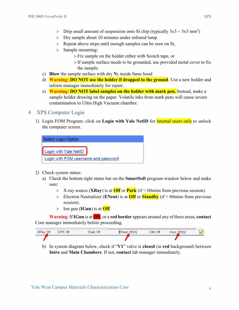
4 XPS Computer Login 1) Login FOM Program: click on Login with Yale NetID for internal users only to unlock
the computer screen.
2) Check system status:
a) Check the bottom right status bar on the SmartSoft program window below and make sure:
> X-ray source (XRay) is at Off or Park (if < 60mins from previous session). > Electron Neutralizer (ENeut) is at Off or Standby (if < 60mins from previous
session). > Ion gun (IGun) is at Off.
Warning: If IGun is at ON, or a red border appears around any of these areas, contact Core manager immediately before proceeding.
b) In system diagram below, check if “V1” valve is closed (in red background) between Intro and Main Chambers. If not, contact lab manager immediately.

PHI 5000 VersaProbe II XPS
7
Yale West Campus Materials Characterization Core
3) Sign in on the logbook and write down the Main Chamber and Intro Chamber initial pressure on Cold Cathode gauge as highlighted in above diagram before sample loading.
4) Report to manager immediately if the Cold Cathode pressure gauge reads above 4E-4 Pa.
5 Create Sample in SmartSoft Program
1) Click tab on top of SmartSoft-VersaProbe program to enter the System window, then click the Sample Transfer tab on the right side to enter Sample Transfer tab as shown below. Warning: the software should never be closed after use. If software restart is required, click the icon on the desktop and click OK to open. No password required.
2) Click button on above window to open Create Platen (sample) window below. Enter a new platen name and hit OK. Do not use previous platen name which was affiliated with previous sampling position info.

PHI 5000 VersaProbe II XPS
8
Yale West Campus Materials Characterization Core
Warning: NEVER change or create a new platen name in the middle of data collection. This will lead to hardware damages inside vacuum.
3) In the popup Data Manager Properties window below, choose the right type of sample holders.
a) Select 25 mm for regular 25 mm sample holder. b) Select 60 mm for regular 60 mm sample holder. c) Select Angle-4 position for Angle Resolved sample holder.
4) Click Directory and specify the data Acquisition Directory
5) Hit OK and Close above window.
6 Sample Loading into Intro Chamber Warning: DO NOT use the holder if dropped to the ground. Use a new holder and inform manager immediately for repair.
1) The sample holder must be cleaned with nitrogen gas to remove any loose particles, hair or fibers that may exist on the holder.

PHI 5000 VersaProbe II XPS
9
Yale West Campus Materials Characterization Core
2) Turn ON the Main Chamber light.
3) Confirm no samples inside Main Chamber: a) Look through the view port to confirm no samples in the Main Chamber, and then turn
off Main Chamber light b) Check the system diagram below and make sure that the Stage is empty as
highlighted. Report to lab manager immediately if not. Warning: Never leave samples in Main Chamber. The sample can be left inside the intro chamber after finish, which will be discarded by next user.
4) In above system diagram in, check if (V3) valve is in green indicating the Intro
Chamber being pumped, then click in the Sample Transfer window below:
PHI 5000 VersaProbe II XPS
10
Yale West Campus Materials Characterization Core
5) Right after venting started, put on gloves and hover on the glass cover. Do not touch cover.
6) Remove the glass cover and place the backside on the XPS table with a clean Kimwipe underneath. Warning:
> Never touch the sample loading port with exposed skins, > Never touch the camera atop the loading port, > The sample holder must have been cleaned with nitrogen gas.
Serious chamber leaking or pump damage might happen if any fibers or particles are sucked into vacuum.
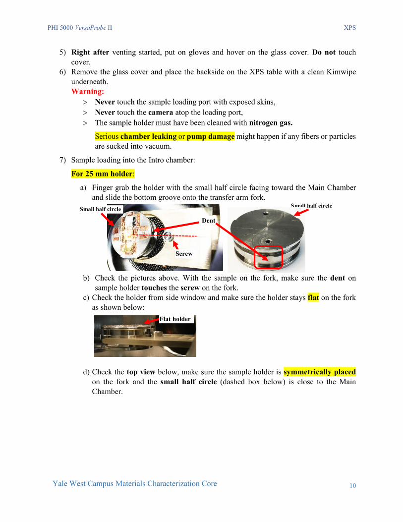
7) Sample loading into the Intro chamber:
For 25 mm holder:
a) Finger grab the holder with the small half circle facing toward the Main Chamber and slide the bottom groove onto the transfer arm fork.
b) Check the pictures above. With the sample on the fork, make sure the dent on sample holder touches the screw on the fork.
c) Check the holder from side window and make sure the holder stays flat on the fork as shown below:
d) Check the top view below, make sure the sample holder is symmetrically placed
on the fork and the small half circle (dashed box below) is close to the Main Chamber.
Flat holder
Dent
Screw
Small half circle Small half circle

PHI 5000 VersaProbe II XPS
11
Yale West Campus Materials Characterization Core
For 60 mm holder:
a) Use the tong to grab the side cut of the holder and slide the bottom groove onto the transfer arm fork as shown below:
b) Make sure from the top-view below that the flat cut on the sample holder is on the
right side (away from the main chamber).
c) Hand adjust/turn the sample holder slightly and make sure the holder can be stopped
by the screw on the transfer rod.
Tong
Side cut
Main Chamber
Flat cut Main Chamber
PHI 5000 VersaProbe II XPS
12
Yale West Campus Materials Characterization Core
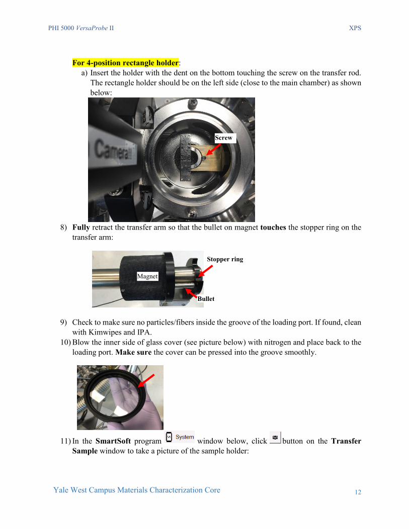
For 4-position rectangle holder:
a) Insert the holder with the dent on the bottom touching the screw on the transfer rod. The rectangle holder should be on the left side (close to the main chamber) as shown below:
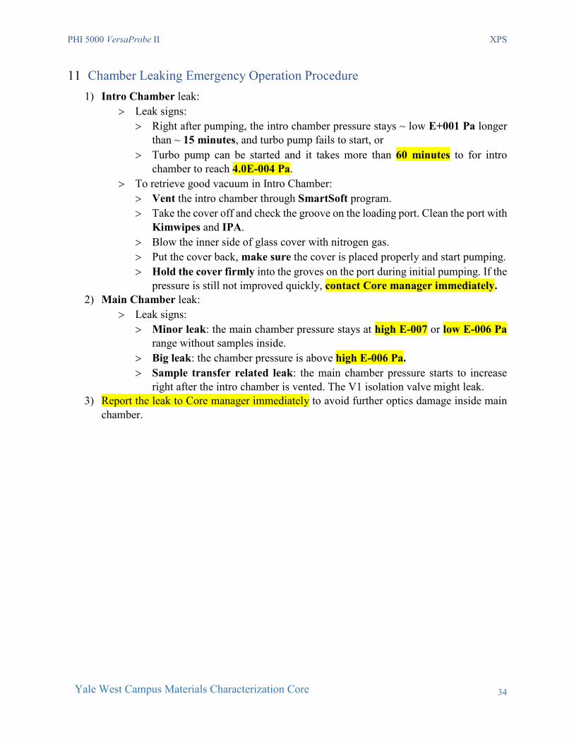
8) Fully retract the transfer arm so that the bullet on magnet touches the stopper ring on the transfer arm:
9) Check to make sure no particles/fibers inside the groove of the loading port. If found, clean
with Kimwipes and IPA. 10) Blow the inner side of glass cover (see picture below) with nitrogen and place back to the
loading port. Make sure the cover can be pressed into the groove smoothly.
11) In the SmartSoft program window below, click button on the Transfer Sample window to take a picture of the sample holder:
Stopper ring
Magnet
Bullet
Screw

PHI 5000 VersaProbe II XPS
13
Yale West Campus Materials Characterization Core
12) Pay attention to the camera shutter sound Wait for several seconds for picture loading
into the program. Be patient, NEVER double click camera button.
13) Click the tab next to to enter the Sample window. Check the sample
holder photo and make sure the blue circle aligns well with the bottom half (smaller circular part) of the 25 mm sample holder. If not, contact lab manager. For 60mm and Angle-4 position holder, the blue circle/rectangle should match the entire holder.
14) Click and click button on the Sample Transfer window below and quickly go back to the loading port; hold and press the glass cover until pumping starts after air hissing sound. Warning: The Intro Chamber might be leaking if the cover is not pressed during pumping.

PHI 5000 VersaProbe II XPS
14
Yale West Campus Materials Characterization Core
15) Monitor the Intro Chamber pressure change on the system diagram:
a) The Intro pressure gauge reading as highlighted below should drop from atmosphere pressure to ~3.0E+001 Pa in ~5 minutes;
b) The Cold Cathode gauge should start reading from ~ 1E-002 Pa: c) Wait until the pressure drops to 4.0E-004 Pa before sample transfer can be started.
Typically, it takes ~15 minutes for dry samples. If it takes longer than one hour, consider removing samples from intro chamber for further drying treatment.
7 Sample Transfer into Main Chamber 1) Check and make sure the Cold Cathode gauge pressure is below 4.0E-004 Pa.

PHI 5000 VersaProbe II XPS
15
Yale West Campus Materials Characterization Core
2) Turn on the Main Chamber light.
3) Wear glove on right hand for sample transfer. 4) Read through Step 5) to 12) below before proceeding.
5) Click in the Transfer Sample window below to start sample transfer from Intro Chamber to Main Chamber Warning: NEVER stop the transfer process in the middle and force to close the SmartSoft program in Task Manager. Contact Core manager immediately if did by accident.
6) Wait for the following window to appear. DO NOT click OK button.
7) Turn the magnet and let the flat plane face upward. Make sure the flat surface aligns the
open cut on the back stop ring as highlighted by the dashed line below:

PHI 5000 VersaProbe II XPS
16
Yale West Campus Materials Characterization Core
8) Grab the magnet with the right-hand thumb placed on the left side of magnet and slowly move toward main chamber until finger touches the stopper ring as show below.
9) Watch the sample holder in main chamber, and retract thumb and move very slowly until
the magnet touches the front stopp ring (see picture below).
a) If a slight resistance is felt before magnet touches the stopper ring (above
image): > DO NOT force the transfer rod into the main chamber stage to DAMAGE
parts. > Retract the rod with sample holder back into Intro chamber and follow
software instructions to close the V1 valve. > Inform manager immediately for help.
b) Alternately for off-peak users who are very familiar with operation:
> In the tab, right click on the sample holder picture on the system diagram and click Properties as show below. Note: the sample holder picture has been moved to Main Chamber after initial transfer failure as shown below:
Stop ring
Magnet
Front stop ring Magnet
Flat plan on Magnet
Cut on back stop ring

PHI 5000 VersaProbe II XPS
17
Yale West Campus Materials Characterization Core
> In the popup Data Manager Properties window below, choose Intro in the
dropdown list for Sample Location. Then click Close button at the bottom. The Sample holder picture will be moved into Intro Chamber.
> Click tab to enter the side Stage menu and click in the Advanced Control region as shown below.

PHI 5000 VersaProbe II XPS
18
Yale West Campus Materials Characterization Core
> Wait the stage initialize (stage moves in X, Y, Z, Rotation and Tilt) to finish ( < 5 minutes ) and try sample transfer again.
> If still feels a slight resistance, retract the rod with the sample holder, close the V1 valve and Inform manager immediately for help.
10) Keep the transfer arm at the transfer position with magnet touching stopper ring, go back
to the computer and click OK button on the popup window in Step 6) above.
11) Wait the following window to appear. DO NOT click OK to damage parts on the stage.
12) Go back to the chamber, watch the holder in main chamber. Rest right hand on the transfer
arm and very slowly pull back the arm from the stage to avoid sample holder being dragged away/dropped from the stage. Once the front fork leaves the stage move faster to fully retract the transfer arm.
13) Go back to the computer and click OK on the popup window in Step 9). 14) Wait until the stage is driven to the center.

PHI 5000 VersaProbe II XPS
19
Yale West Campus Materials Characterization Core
15) Note that the sample holder picture should appear inside the main chamber after finish. 16) Turn off Main Chamber light. 17) Wait ~ 5 - 30 mins for the main chamber pressure to reach 5E-007 Pa before proceeding
to XPS Scan. 18) Consider liquid nitrogen cooling on the stage with under following circumstances:
a) If the pressure stays in the 10E-6 Pa range for more than 30 mins, b) If the pressure rises to higher E-6 Pa right after transfer.
8 XPS Scan 8.1 Stage Z-Alignment
1) Check and make sure the Main Chamber pressure reaches below 5E-007 Pa.
2) Click tab on top of program to enter Sample window. 3) Hover mouse cursor over the sample photo window on the left, scroll mouse wheel to
enlarge photo and find the sample to be analyzed.
4) Right click mouse on the first intended analysis area and select Drive To Click on the
dropdown menu, the yellow box should move to the selected area. Do Not drag yellow box.
5) Click Stage tab on the right side of Sample window to enter Stage Parameters window as show below:
enlarge

PHI 5000 VersaProbe II XPS
20
Yale West Campus Materials Characterization Core
6) Input initial stage Z height in above window: > For 25mm and 60mm holder:
> For thin samples (lower than 1 mm), put 15 inside Z(mm) space in above window and hit Enter on keyboard.
> For thick samples, put 12 mm instead. > For 4-position rectangle holder or thick samples on 25mm and 60mm holders, put
12 mm instead.
7) Click button next to Z(mm) space and wait for the sample stage moving to entered
heights next to button.
8) Click button as highlighted on top of SXI image window below to start Z-Align
9) Watch closely several windows popping up including Ion Neutralization Standby,
Turning E-Neut On, Ion Neutralization On and Filament Startup. Report to Core manager immediately if the Z-Align stops at any of those windows for more than 5 minutes.
10) Wait for the following Z Height window to appear and watch the Z height change in the
space next to button. The typical height after alignment should be ~ 16-17 mm. The Z Align will fail if the number reaches above 18 mm. Report to Core Manager immediately if it happens.
8.2 Create multiple sample positions 1) After Z-Align, right click inside the yellow box on the Sample Photo and select Create
Point at Stage to create the first sampling position as shown in the position list below:
2) Input the position name in the Name column and choose Point in the Type column as highlighted below:

PHI 5000 VersaProbe II XPS
21
Yale West Campus Materials Characterization Core
3) Right click on other samples or interested areas and select Create Point to define all other scan positions.
8.3 XPS Survey (Full Range) Scan
1) Click tab on top tab menu to enter XPS analysis window and click Spectrum tab on the right side.
2) In Source window below, choose FXS (Focused X-ray Source), and in Source Setting window choose 200u50W15kV (X-ray beam size: 200 µm, power: 50 W, and e-beam energy: 15 kV).
3) If sample is sensitive to X-ray radiation, e.g. XPS peaks shift or widen during scan, choose
100u100W20kV_HP to minimize sample damage and go back to Step 2) in Section 8.2 to choose HP in the Type column in the sample Position List.
4) Click on top left of Regions window to enlarge the XPS Regions (Spectrum) window as shown below:
5) Click in above window to erase previous setup parameters.

PHI 5000 VersaProbe II XPS
22
Yale West Campus Materials Characterization Core
6) Click on button on the window above to open the Periodic Table below and click to start a Spectral Survey (Su) Scan.
7) Click OK button on the Periodic Table to close the window. 8) Scan parameter setup in the popup XPS Regions window:
a) Input the number of sweeps/scans in the column as highlighted below, typically choose 5 times; consider 10 times or more sweeps for noisy spectrum.
b) Input pass energy value in the column, typically 187.850 eV; 117.4 eV can also be used to improve spectral resolution but more sweeps is needed for smooth peaks.
c) Input scan steps in the , typically 0.8000 eV; 0.4 eV can also be used for higher resolution.
d) Close the popup XPS Regions window.
9) Click on button on the bottom of the Spectrum window to open XPS Acquisition Setup window and follow the instructions highlighted on the window:
5

PHI 5000 VersaProbe II XPS
23
Yale West Campus Materials Characterization Core
Select Auto
Select Auto
Select Disabled
Select Enabled
Select Standard
Select Auto
Select Disabled
Select Enabled

PHI 5000 VersaProbe II XPS
24
Yale West Campus Materials Characterization Core
10) Hit in Spectrum window below to start Survey scan
11) Wait the following windows to appear:
12) The Survey spectrum will appear in the Spectral window below. The filename as
highlighted below is in the form of “platen name.serial number.spe” followed by scan type. Scan type is Su1s for survey.
13) The data files will be automatically saved into specified folder which can be viewed using
MultiPak program.
14) If the spectral acquisition fails due to Z-Align failure on specific samples, follow the instructions in Section 8.1 Steps 6) to 10) to perform manual Z-Align.

PHI 5000 VersaProbe II XPS
25
Yale West Campus Materials Characterization Core
8.4 Regional (Elemental) Scan
1) Once survey scan is complete, click on the Survey spectrum to start Peak ID
2) Click on top left corner of Regions window to enlarge the XPS Regions (Spectrum) window below:
3) Click on button on the window above to open the Periodic Table below and click on the table to add intended elements into XPS Regions window/list.
4) Scan parameter setup in the popup XPS Regions window below:

PHI 5000 VersaProbe II XPS
26
Yale West Campus Materials Characterization Core
a) Input the number sweeps/scans in the column below, typically 5 ~ 20 times depending on peak intensity collected in survey scan. Consider more sweeps for weak element peaks.
b) Input pass energy value in the column, typically 23.500 eV. For low intensity valence band scan, 11.75 eV can be chosen but more sweeps are needed.
c) Input scan steps in the , typically 0.1000 eV. Smaller step of 0.05 eV is good for higher resolution valence band scan but more sweeps needed.
d) Close the popup XPS Regions (Spectrum) window.
5) Click on to open XPS Acquisition Setup window as shown in Step 9) in Section 8.3 and select Disabled on XPS: Z-Align in Z-Align section.
6) Hit in Spectrum window to start Region scan
7) Wait until the following windows to appear
8) The Region Scan spectra will appear in the Spectral Window following the sequence in Regions table.

PHI 5000 VersaProbe II XPS
27
Yale West Campus Materials Characterization Core
9) Add Q (Add to Queue mode) if interested elements are different on different samples:
a) Click on to open XPS Acquisition Setup window as shown in Step 9) in Section 8.3 and check OFF on XPS: Z-Align in Z-Align section.
b) Set up a complete element list in the Regions window, c) Go back to Sample window, check ONLY intended sample positions on the list, d) Go to XPS window, select ONLY the group of elements for intended sample
positions just chosen,
e) Hit button in Spectrum window to see added selected queue to the Add Q window below. Make sure clear queues added by previous users.
f) Minimize above window, go back to Sample window and repeat Step b) – e) until
all sample positions are selected;
g) Maximize the Add Q window and hit to start spectral scan.

PHI 5000 VersaProbe II XPS
28
Yale West Campus Materials Characterization Core
9 Closing XPS Measurement 1) Put gloves on right hand and get ready for sample extraction. 2) Extract samples from Main Chamber:
a) Check Intro Chamber status before sample extraction: > Click System tab to enter the Transfer Sample window on the right side of the
window, if the V3 valve is in green , indicating the Intro Chamber is in good vacuum, then skip Step b) below;
> Else If V3 valve is in red , continue Step 2b) below
b) Click button on the Sample Transfer window, watch the Intro pressure reaches below 4.0E-004 Pa on Cold Cathode gauge.
c) Click below to start Sample Extraction

PHI 5000 VersaProbe II XPS
29
Yale West Campus Materials Characterization Core
d) Wait until the following window appears. DO NOT click OK button.
e) Grab the magnet with the right-hand thumb placed on the left side of magnet and slowly move toward main chamber until finger touches the stopper ring.
f) Watch the sample holder in main chamber, retract thumb and move very slowly until the magnet touches the stopper ring (see picture below). Warning: > STOP forcing transfer arm into the main chamber stage even if a slight
resistance is felt. > Retract the EMPTY rod back into Intro chamber and follow instructions to
close the V1 valve. > Inform manager immediately to prevent possible damages.
g) Keep the transfer arm at the transfer position with magnet touching stopper ring,
go back to the computer and click OK button on the popup window in Step d) above.
h) Wait the following window to appear. DO NOT click OK to damage parts on the stage.
i) Go back to the chamber, watch the holder in main chamber. Rest right hand on the transfer arm and very slowly pull back the arm from the stage to make sure sample holder stays on the fork during transfer. Once the front fork leaves the stage move faster to fully retract the transfer arm.
j) Go back to the computer and click OK on the popup window in Step h).
Stopper Ring
Magnet

PHI 5000 VersaProbe II XPS
30
Yale West Campus Materials Characterization Core
k) Wait until the stage is driven to the center.
3) Check the bottom right status bar on the SmartSoft program window below and make sure:
> X-ray source (XRay) is at Park. > Electron Neutralizer (ENeut) is at Standby. > Ion gun (IGun) is at Off.
Waring: If IGun was left at ON or a red border appears around any of these areas, contact Core manager immediately before proceeding.
4) Turn OFF chamber light.
5) Check liquid nitrogen dewar if used and clean any water left around on the table. 6) If your samples can be discarded, then skip Step 8) – 10) below. The next user should clear
your samples on the holder. 7) Otherwise continue to the steps below to retrieve your samples from Intro Chamber.
Park Standby

PHI 5000 VersaProbe II XPS
31
Yale West Campus Materials Characterization Core
8) Click on the Sample Transfer window below to vent the Intro Chamber
9) Right after venting started, put on gloves and hover on the glass cover. Do not touch cover.
Slide the sample holder off from the transfer arm and put the cover back.
10) Click button on the Sample Transfer window below and quickly go back to the loading port; hold and press the glass cover until pumping starts after sucking air sound.
11) Watch the Cold Cathode gauge reads 4.0E-004 Pa before logoff FOM. It should just take ~ 5- 10 minutes.
12) Keep SmartSoft programs maximized on the screen. Never close the program. 13) Back up your data either through internet (box.yale.edu) or using Core USB drive. Do not
use personal USB drive.
14) Logoff FOM program: click the icon on the taskbar below to activate the FOM program and click Logoff button in the FOM window. If any issues occurred during scan, check “Something wrong” and type message in the Comments space.
15) Sign off on the logbook.

PHI 5000 VersaProbe II XPS
32
Yale West Campus Materials Characterization Core
16) Remove samples from the holder left by previously users and clean the surface with clean wipes and IPA.
17) Store the sample holder and other tools back into the tool box.

PHI 5000 VersaProbe II XPS
33
Yale West Campus Materials Characterization Core
10 Some Analysis Concepts > High X-ray Power High sensitivity but poor spatial resolution (beam size is bad) > Low X-ray Power Low sensitivity but good spatial resolution (beam size is good) > High Pass energy High sensitivity but poor energy resolution (peak is FAT) > Low Pass energy Low sensitivity but good energy resolution (peak is THIN) > Big Step size Acquire time is short but peak shape (resolution) is bad > Small Step size Acquire time is long but peak shape (resolution) is good > High sensitivity Signal-to-Noise is better so total acquire time can be shorter > Low sensitivity Signal-to-Noise is worst so total acquire time needs to be longer > Sensitivity = Signal Intensity or counts
PHI 5000 VersaProbe II XPS
34
Yale West Campus Materials Characterization Core
11 Chamber Leaking Emergency Operation Procedure 1) Intro Chamber leak:
> Leak signs: > Right after pumping, the intro chamber pressure stays ~ low E+001 Pa longer
than ~ 15 minutes, and turbo pump fails to start, or > Turbo pump can be started and it takes more than 60 minutes to for intro
chamber to reach 4.0E-004 Pa. > To retrieve good vacuum in Intro Chamber:
> Vent the intro chamber through SmartSoft program. > Take the cover off and check the groove on the loading port. Clean the port with
Kimwipes and IPA. > Blow the inner side of glass cover with nitrogen gas. > Put the cover back, make sure the cover is placed properly and start pumping. > Hold the cover firmly into the groves on the port during initial pumping. If the
pressure is still not improved quickly, contact Core manager immediately. 2) Main Chamber leak:
> Leak signs: > Minor leak: the main chamber pressure stays at high E-007 or low E-006 Pa
range without samples inside. > Big leak: the chamber pressure is above high E-006 Pa. > Sample transfer related leak: the main chamber pressure starts to increase
right after the intro chamber is vented. The V1 isolation valve might leak. 3) Report the leak to Core manager immediately to avoid further optics damage inside main
chamber.