Standard operating procedure Biodex System 3 dynamometer
13
\\kelty\rsports\Labs\sops\biodexSystem3\SOPbiodexSystem3.docx Revised: 2020-09-22 Standard operating procedure Biodex System 3 dynamometer Introduction Do not use this equipment unless you have been trained and are competent to do so This procedure is in addition to the manufacturer’s operating manual. Read the risk assessments RA01, RA02, RA03, RA04, Metabolic testing and for any additional equipment used such as ergometers before starting work. These documents are kept in the folder alongside the machine and on the laboratory safety website. Biodex System 3 dynamometer This dynamometer is used for static and dynamic training and testing. The Biodex can operate in Isokinetic, Passive, Isometric, Isotonic and Reactive Eccentric modes. It can be configured to exercise the majority of muscles in the body. Force data can be recorded on an external computer. Pre operation inspection Check the condition of all items of equipment for damage or misuse, report any concerns to the laboratory technician Seat Securing straps Actuator arm 3 Movable axes Isolated power supply Computer Motion limit stop Machine controls Comfort stop switch Emergency stop
Transcript of Standard operating procedure Biodex System 3 dynamometer

\\kelty\rsports\Labs\sops\biodexSystem3\SOPbiodexSystem3.docx Revised: 2020-09-22
Standard operating procedure Biodex System 3 dynamometer
Introduction Do not use this equipment unless you have been trained and are competent to do so
This procedure is in addition to the manufacturer’s operating manual.
Read the risk assessments RA01, RA02, RA03, RA04, Metabolic testing and for any additional
equipment used such as ergometers before starting work.
These documents are kept in the folder alongside the machine and on the laboratory safety website.
Biodex System 3 dynamometer This dynamometer is used for static and dynamic training and testing. The Biodex can operate in
Isokinetic, Passive, Isometric, Isotonic and Reactive Eccentric modes. It can be configured to exercise
the majority of muscles in the body. Force data can be recorded on an external computer.
Pre operation inspection Check the condition of all items of equipment for damage or misuse, report any concerns to
the laboratory technician
Seat
Securing straps
Actuator arm
3 Movable axes
Isolated power
supply
Computer
Motion limit stop
Machine controls
Comfort stop
switch
Emergency stop

\\kelty\rsports\Labs\sops\biodexSystem3\SOPbiodexSystem3.docx Revised: 2020-09-22
Check the condition of all cables and connections before turning the dynamometer on. Do
not use the equipment if you find any damage
If you wish to record test data contact the laboratory technician
Do not use the equipment if there are any signs of damage to the electrical supply cables or
connections
Make sure that the equipment is clean, wipe any soiled areas with a soft cloth or tissue
moistened with detergent solution before use and between participants
Precautions Never try out a new machine configuration on any person. Always check the full range of
motion is safely within the range of motion of the participant by hand before seting up the
test
Always check the motion limit stop prevents possible overextension of joints. Software can
malfunction and harm the participant
Screen participants as described in risk assessments RA01, RA02, RA03 and RA04
Make sure the participant is aware of how the equipment works and that they can stop the
test if they feel any discomfort. Demonstrate the participant comfort stop button and
emergency stop
Read the manual (APPLICATION/OPERATION MANUAL) before use
This machine has several parts connected by cables. Care should be taken to avoid tripping
over cables while reconfiguring the machine. Before the participant arrives make sure the
cables are clear of their path to the machine.
Participants should not be left unattended at any time when using the machine
The participant should always have access to the comfort stop button
Make sure the test sequence is complete before removing the participant from the
dynamometer.
Make sure there are no obstructions to the motion of the dynamometer head and
attachments such as items left lying on the machine before turning on

\\kelty\rsports\Labs\sops\biodexSystem3\SOPbiodexSystem3.docx Revised: 2020-09-22
Configuring the dynamometer The Biodex is highly configurable, and it is not in the scope of this SOP to cover all possibilities. Here
is how to go about a general configuration.
Positioning the dynamometer head
1. Rotation knob: Loosen counter clockwise to rotate the head. Note the head rotates until it
hits a stop. Do not force the head past the stop.
2. Tilt knob: Support the head. Loosen counter clockwise to obtain the desired tilt of the head.
3. Height knob: Loosen counter clockwise to release the head and push gently up and down to
obtain the desired position
4. Foot pedals: Press down to release the linear slide and push the whole assembly to the
desired position on the track. Release the pedal to lock in place.
5. Red dot for orientation of dynamometer shaft
6. Button for counter clockwise rotation
7. Button for clockwise rotation
8. Hold/Resume button
9. 2 x Comfort stops
10. Transport lock
11. Position scale
12. Yoke

\\kelty\rsports\Labs\sops\biodexSystem3\SOPbiodexSystem3.docx Revised: 2020-09-22
Positioning the chair
1. Rotation handle: Loosen counter clockwise to rotate the head.
2. Attachment receiving tubes
3. Foot pedal: Press down to release the linear slide and push the whole assembly to the
desired position on the track. Release the pedal to lock in place.
4. Height pedals: Adjust the motorised seat up and down.

\\kelty\rsports\Labs\sops\biodexSystem3\SOPbiodexSystem3.docx Revised: 2020-09-22
5. Cervical support adjustment knob: Support the seatback with one hand and loosen counter
clockwise. Adjust as desired.
6. Seatback tilt leaver: Support the seatback with one hand and loosen counter clockwise.
Adjust as desired.
7. Seat depth handle: Loosen counter clockwise. Adjust slide to adjust as desired.
8. Stabilization handles: Hand grips for participant to grab during exercise
The control panel

\\kelty\rsports\Labs\sops\biodexSystem3\SOPbiodexSystem3.docx Revised: 2020-09-22
Turning the machine on
Check the electrical connections are secure and undamaged
Turn the mains electricity on at the wall
Turn on the main power switch to the rear of the control unit (1)
Turn on the controller power and the dynamometer power (2,3)
Turn on the computer power
Setting up before a test Turn the machine on
Once the machine has initialised you should see the message REMOVE ATTACHMENT,
PRESS START on the system status window. Remove any attachments and press Start
The dynamometer will move to calibrate. When requested to do so on the system status
window press Start.
The machine is now in setup mode, the dynamometer shaft is unpowered and the Set Limits
buttons should flash. This is when we must setup the exercise limits with the help of the
participant
Press Panel Control
Choose and install the correct attachment, align the dots on shaft and attachment then
secure with the locking knob
Press Select attachment and cycle through the options until you find the correct entry
Press any button to accept
Position and stabilize subject correctly for the intended protocol by adjusting the seat
height, seat position and seatback tilt.
Adjust Dynamometer height, angle, rotation, and position
Secure appropriate stabilization straps.
Make sure the anatomical axis of the joint is aligned correctly with the dynamometer shaft.
Set the Range of motion (ROM)
Computer Power
\\kelty\rsports\Labs\sops\biodexSystem3\SOPbiodexSystem3.docx Revised: 2020-09-22
o Have the participant perform the initial movement of the exercise over the full
range of motion then hold their position at the end. Press the relevant Set Limit
button for the direction, Away or Toward.
o Have the participant perform the return motion over the full range of motion and
hold, press the Set Limit button for that direction
o Both buttons should now have stopped flashing
Isokenetic Mode In this mode, the dynamometer acts to control velocity, allowing the subject to accelerate up to, but
no higher than, the maximum speed value selected for each direction of shaft rotation. The
participant can slow down or change direction of movement at any point within the range of motion.
After completing the Setup mode routine, select Isokinetic mode from the control panel
The Percent ROM buttons can selectively reduce the total range of motion established
during participant setup. Use the Percent ROM Away and Toward buttons to decrease the
percent ROM allowed in either direction
Set contraction type, use the Contraction Away or Toward button to select the appropriate
contraction type for each direction of movement. The contraction type selected for each
direction of movement is indicated by the contraction button LED. When using eccentric
contractions, the patient will have to apply 10% of the set torque value to initiate motion
and exceed the torque limit value to stop. The direction the attachment is moving will
determine the contraction
Set speed. Use the Speed Away/Toward buttons on the control panel to set the maximum
velocity for each direction of movement.
Set End Stop Cushion. Use the End Stop Cushion button to set the point in each direction of
the participant’s ROM at which deceleration will begin. The cushion level selected is
displayed in the window immediately to the right of the button.
Inform participant that the test or exercise session is ready to begin and that the
dynamometer will now allow for rotation of the dynamometer shaft.
Press Start to begin the test or exercise session. The participant will not experience
resistance until meeting or exceeding the pre-selected speed. If the subject movement
stops, resistance stops
NOTE: Always be sure the Control Panel settings are correct before engaging this device with the
Start button. Set range of motion limits after placing subject into restraints. Have subject
move through ROM prior to starting test or exercise. Always reset range of motion limits
or press Setup when proceeding from one joint, subject, or attachment to another.
Passive mode In Passive mode the dynamometer provides continuous motion at constant velocity. Direction
changes occur when range of motion limits are reached. In Passive mode, the dynamometer
initiates motion when the Start button is pressed.
After completing the Setup mode routine, select Passive mode from the control panel
The Percent ROM buttons can selectively reduce the total range of motion established
during participant setup. Use the Percent ROM Away and Toward buttons to decrease the
percent ROM allowed in either direction

\\kelty\rsports\Labs\sops\biodexSystem3\SOPbiodexSystem3.docx Revised: 2020-09-22
Set Pause. The Pause buttons (Away and Toward toggles) on the Control Panel allow the
introduction of time delays between each direction of motion
Set speed. Use the Speed Away/Toward buttons on the control panel to set the maximum
velocity for each direction of movement
Set Torque Limits. The Torque buttons, Away and Toward. If the dynamometer detect
excessive torque it will stop moving until the torque is reduced below the limit
Set End Stop Cushion. Use the End Stop Cushion button to set the point in each direction of
the participant’s ROM at which deceleration will begin. The cushion level selected is
displayed in the window immediately to the right of the button.
Inform participant that the test or exercise session is ready to begin and that the
dynamometer will now allow for rotation of the dynamometer shaft.
Press Start to begin the test or exercise session. The system will ramp up to the selected
speed.
NOTE: For Passive mode dynamometer speeds of 75 degrees/sec. and higher, you must press the
Start button twice for high-speed enable.
NOTE: Always be sure the Control Panel settings are correct before engaging this device with the Start button. Set range of motion limits after placing subject into restraints. Have subject move through ROM prior to starting test or exercise. Always reset range of motion limits or press Setup when proceeding from one joint, subject, or attachment to another.
Isometric Mode In this mode, the dynamometer holds still at any selected point in the range of motion. Significant
change in joint angle and overall muscle length does not occur.
After completing the Setup mode routine, select Isometric mode from the control pane
Press and hold down the Towards/Away Button for the desired direction to free up the
dynamometer shaft. While holding down the Towards/Away Button, instruct/assist the
subject to move the limb to the desired point in the ROM. Release the Rotate Button to
select the ROM position
Inform patient that the test or exercise session is ready to begin. Press Start to begin the test
or exercise session
Range of Motion changes are made by holding down the Towards/Away Button and moving
the limb in the corresponding direction. Once the desired point in the range of motion is
met, the button is released and the attachment locks into position.
NOTE: Always be sure the Control Panel settings are correct before engaging this device with the
Start button. Set range of motion limits after placing subject into restraints. Have subject move
through ROM prior to starting test or exercise. Always reset range of motion limits or press Setup
when proceeding from one joint, subject, or attachment to another.
Isotonic Mode
In this mode, the dynamometer requires a minimum set torque to move the arm
After completing the Setup mode routine, select Isotonic mode from the control panel
Set Percent ROM. The Percent ROM buttons are used to selectively reduce the total range of
motion established during patient setup. Use the Percent ROM Away and Toward buttons to

\\kelty\rsports\Labs\sops\biodexSystem3\SOPbiodexSystem3.docx Revised: 2020-09-22
decrease the percent ROM allowed in the either direction. Do not set the range of motion at
the extreme end points
Set contraction type, concentric/concentric, concentric/eccentric or eccentric/concentric.
For Isotonic mode, the system automatically defaults to concentric/concentric movement as
indicated by the contraction button LEDs. To alter this section, use the Contraction Away or
Toward button to select the appropriate contraction type for each direction of movement.
The contraction type selected for each direction of movement is indicated by the contraction
button LED. The speed of the eccentric contraction can be controlled (faster eccentric
speeds produce greater torque than slower eccentric speeds.)
Set Torque Limits Toward and Away. In Isotonic Mode, the Torque buttons are used to
specify a minimum torque threshold. During the exercise or test session, when this threshold
is surpassed by the subject, isotonic motion can occur
Set End Stop Cushion. Use the End Stop Cushion button to set the point in each direction of
the subject’s ROM at which deceleration will begin. The cushion level selected is displayed in
the window immediately to the right of the button. As a general rule, “hard cushions” (high
numbers) are used for testing applications while “soft” cushions (low numbers) are selected
for rehabilitation applications. Inform patient that the test or exercise session is ready to
begin and that the dynamometer will allow for rotation once the preset torque threshold is
obtained. Press Start to begin the test or exercise session.
NOTE: Always be sure the Control Panel settings are correct before engaging this device with the
Start button. Set range of motion limits after placing subject into restraints. Have subject move
through ROM prior to starting test or exercise. Always reset range of motion limits or press
Setup when proceeding from one joint, subject, or attachment to another.
\\kelty\rsports\Labs\sops\biodexSystem3\SOPbiodexSystem3.docx Revised: 2020-09-22
Reactive Eccentric mode In this mode the dynamometer responds to torque exerted by the patient by moving against the applied force. The Torque buttons on the Control Panel are used to specify a window of desired human force output. The participant is required to maintain torque within the specified range to keep the shaft moving. Reactive Eccentric mode allows for direction changes at any point in the range of motion.
After completing the Setup mode routine, select Reactive Eccentric mode from the control panel.
Set Percent ROM. The Percent ROM buttons are used to selectively reduce the total range of motion established during patient setup. Use the Percent ROM Away and Toward buttons to decrease the percent ROM allowed in the either direction.
Set speed. Use the Speed Away/Toward buttons on the control panel to set the maximum velocity for each direction of movement. More eccentric torque will be performed at higher velocities.
Set Torque Limits Toward and Away. In Reactive Eccentric mode, the Torque buttons are used to specify a window of desired subject force output. During the exercise or test session, when 10% of the preset torque limit is being applied by the subject, eccentric motion will occur. Reactive Eccentric motion will stop when applied torque is removed or rises above the set amount. The direction the dynamometer shaft is moving during the eccentric contraction is the torque limit you will need to set. To limit eccentric quadriceps, set the toward limit. To limit shoulder external rotators, set the toward limit.
Set End Stop Cushion. Use the End Stop Cushion button to set the point in each direction of the subject’s ROM at which deceleration will begin. The cushion level selected is displayed in the window immediately to the right of the button. As a general rule, “hard cushions” (low numbers) are used for testing applications while “soft” cushions (high numbers) are selected for rehabilitation applications.
Inform patient that the test or exercise session is ready to begin and that the dynamometer will now allow for rotation of the dynamometer shaft once eccentric resistance meets the specified level. Press Start to begin the test or exercise session.
NOTE: Always be sure the Control Panel settings are correct before engaging this device with the
Start button. Set range of motion limits after placing subject into restraints. Have subject move
through ROM prior to starting test or exercise. Always reset range of motion limits or press Setup
when proceeding from one joint, subject, or attachment to another.
Attachments and setup for specific exercises The Biodex is highly configurable with a number of different attachments to enable a wide range of
exercises. The attachments are detailed below but only the most common exercise setup is detailed
here. Please refer to the manual to configure the Biodex for other exercises.
\\kelty\rsports\Labs\sops\biodexSystem3\SOPbiodexSystem3.docx Revised: 2020-09-22
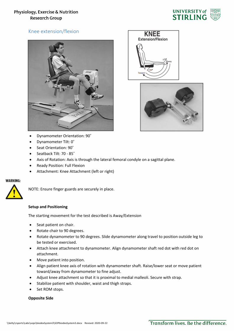
Knee extension/flexion
Dynamometer Orientation: 90˚
Dynamometer Tilt: 0˚
Seat Orientation: 90˚
Seatback Tilt: 70 - 85˚
Axis of Rotation: Axis is through the lateral femoral condyle on a sagittal plane.
Ready Position: Full Flexion
Attachment: Knee Attachment (left or right)
NOTE: Ensure finger guards are securely in place.
Setup and Positioning
The starting movement for the test described is Away/Extension
Seat patient on chair.
Rotate chair to 90 degrees.
Rotate dynamometer to 90 degrees. Slide dynamometer along travel to position outside leg to
be tested or exercised.
Attach knee attachment to dynamometer. Align dynamometer shaft red dot with red dot on
attachment.
Move patient into position.
Align patient knee axis of rotation with dynamometer shaft. Raise/lower seat or move patient
toward/away from dynamometer to fine adjust.
Adjust knee attachment so that it is proximal to medial malleoli. Secure with strap.
Stabilize patient with shoulder, waist and thigh straps.
Set ROM stops.
Opposite Side

\\kelty\rsports\Labs\sops\biodexSystem3\SOPbiodexSystem3.docx Revised: 2020-09-22
Unstrap patient’s knee from attachment and thigh strap.
With patient remaining in chair, slide chair back away from dynamometer.
Press Hold button to retain dynamometer shaft position. Remove attachment. Get knee
attachment for opposite side.
Rotate dynamometer to 90 degrees on opposite side. Slide dynamometer to opposite side of
patient.
Attach knee attachment to dynamometer. Align dynamometer shaft red dot with red dot on
attachment.
Move patient into position.
Align patient knee axis of rotation with dynamometer shaft. Raise/lower seat or move patient
toward/away from dynamometer to fine adjust.
Adjust knee attachment so that it is proximal to medial malleoli. Secure with strap.
Stabilize patient with shoulder, waist and thigh straps.
Reset ROM stops.
All attachments Ankle Hip, knee Forearm,wrist
Shoulder, elbow Shoulder rotation
Load cell output An analogue voltage output is provided on a 3.5mm mono jack plug. The output is 0.5V/100N load.

\\kelty\rsports\Labs\sops\biodexSystem3\SOPbiodexSystem3.docx Revised: 2020-09-22
Cleaning The equipment and the surrounding area need cleaning and sanitizing before and after use and
between participants. Use soft wipes and detergent or 70% alcohol solution. Pay particular
attention to the areas the participant touches and any spillages especially if taking samples of bodily
fluids during the session.
After use Remove any materials used during testing and return any furniture used to its original location. If
you have been testing in an unusual configuration that might confuse of frustrate the next user,
return the machine to a more generic configuration.
Training and supervision Supervisors/line managers should inform users of the risks from the use of the Kin-Com.
Supervisors/line managers should ensure that controls are in place and working and that they are
used correctly.
All those using the Kin-Com should be trained and supervised appropriately.
Electrical Safety Do not use machinery that has obvious damage to body, cable or plug.
All mains powered equipment should have an electrical safety (PAT) testing sticker that is in date. If
not, contact the safety officer.
Turn unit off and unplug when not in use.
First Aid If a minor injury occurs report to a first aider if able to do so. There is a list of first aiders on the
laboratory door. There is a first aid box near the telephone.
In case of emergency Such as a more serious injury. Follow the emergency procedures displayed by the telephone.
Waste Put all clinical waste which includes anything contaminated with bodily fluids in the bins with the
yellow bags. The clinical waste bin should be emptied if more than 2/3 full. Use the bins with black
bags for all other waste such as drinks containers.