
Standard Operating Procedure 1(26) E.ON Elnät Sverige · PDF fileStandard Operating...
26
Dokumentslag Sida Standard Operating Procedure 1 (26) Företag Ersätter tidigare dokument Dokumentid Utgåva E.ON Elnät Sverige AB NUT-091103-027 D10-0015669 11.0 Organisation Giltig fr o m Giltig t o m Anläggning 2017-06-07 Dokumentansvarig Sekretessklass Godkänt av Claes Ahlrot Open Roger Appelberg Titel Technical Requirements for Power Transformers Technical Requirements for Power Transformers.docm LIST OF CONTENTS 1 General ............................................................................................................2 1.1 Scope .........................................................................................................2 1.2 Standards ...................................................................................................2 1.3 Marking .....................................................................................................2 2 Changes compared to earlier version ...........................................................3 3 Electrical, mechanical and other requirements ..........................................3 3.1 Electrical requirements ..............................................................................4 3.1.1 On-load tap-changer and cooling equipment .....................................8 3.1.2 Off-circuit tap-changer .......................................................................8 3.2 Mechanical requirements ..........................................................................8 3.2.1 Transformer tank ................................................................................8 3.2.2 Valves and manhole covers................................................................9 3.2.3 Surface treatment ...............................................................................9 3.2.4 Surge arresters ..................................................................................10 3.2.5 Junction boxes/control cubicles and cables .....................................10 3.3 Other requirements ..................................................................................11 3.3.1 Oil and oil system ............................................................................11 3.3.2 On-Load Tap-Changer (OLTC) .......................................................12 3.3.3 Bushings ...........................................................................................13 3.3.4 Current transformers ........................................................................14 3.3.5 Cooling equipment ...........................................................................16 3.3.6 Surge arresters ..................................................................................17 3.3.7 Auxiliary winding ............................................................................18 3.3.8 Monitoring equipment......................................................................19 3.3.9 Sound power ....................................................................................21 3.3.10 Impact recorder ................................................................................21 4 Functional requirements .............................................................................21 5 Testing ...........................................................................................................23 6 Documentation .............................................................................................25
Transcript of Standard Operating Procedure 1(26) E.ON Elnät Sverige · PDF fileStandard Operating...
Dokumentslag Sida
Standard Operating Procedure 1 (26)Företag Ersätter tidigare dokument Dokumentid Utgåva
E.ON Elnät Sverige AB NUT-091103-027 D10-0015669 11.0Organisation Giltig fr o m Giltig t o m
Anläggning 2017-06-07Dokumentansvarig Sekretessklass Godkänt av
Claes Ahlrot Open Roger AppelbergTitel
Technical Requirements for Power Transformers
Technical Requirements for Power Transformers.docm
LIST OF CONTENTS
1 General............................................................................................................2
1.1 Scope .........................................................................................................21.2 Standards ...................................................................................................21.3 Marking .....................................................................................................2
2 Changes compared to earlier version...........................................................3
3 Electrical, mechanical and other requirements ..........................................3
3.1 Electrical requirements..............................................................................43.1.1 On-load tap-changer and cooling equipment .....................................83.1.2 Off-circuit tap-changer.......................................................................8
3.2 Mechanical requirements ..........................................................................83.2.1 Transformer tank................................................................................83.2.2 Valves and manhole covers................................................................93.2.3 Surface treatment ...............................................................................93.2.4 Surge arresters..................................................................................103.2.5 Junction boxes/control cubicles and cables .....................................10
3.3 Other requirements ..................................................................................113.3.1 Oil and oil system ............................................................................113.3.2 On-Load Tap-Changer (OLTC) .......................................................123.3.3 Bushings...........................................................................................133.3.4 Current transformers ........................................................................143.3.5 Cooling equipment...........................................................................163.3.6 Surge arresters..................................................................................173.3.7 Auxiliary winding ............................................................................183.3.8 Monitoring equipment......................................................................193.3.9 Sound power ....................................................................................213.3.10 Impact recorder ................................................................................21
4 Functional requirements .............................................................................21
5 Testing ...........................................................................................................23
6 Documentation .............................................................................................25
E.ON Elnät Sverige AB Standard Operating Procedure 2 (26)
Claes Ahlrot 2017-06-07 D10-0015669
Technical Requirements for Power Transformers.docm
1 General
1.1 ScopeThis document constitutes E.ON Elnät Sveriges technical demands at procurement of power transformers.These requirements cover the general demands made by E.ON Elnät Sverige on three-phase, 50 Hz, oil-immersed, power transformers with rated power 6.3 MVA and above, and highest voltage for equipment 12-420 kV.
1.2 StandardsThe transformer supplied with accessories shall be designed, manufactured and tested in accordance with the latest edition of the Swedish standards. If Swedish standard is missing corresponding European standard shall be applied. In the event of differences between this document and the relevant standard, the technical requirements in this document shall have precedence.
1.3 MarkingThe rating plate shall contain all rated data for the transformer, the serial number, year of manufacture, weights, type of oil, vacuum proof tank, etc. The connections used shall be shown. On transformers with tap-changer, the tapping position shall also be shown.
Rating plates and signs shall be made of stainless steel. Rating plate shall be provided on the operating side of transformer. The plates and signs shall be secured by stainless steel screws.
Transformers with tap-changers shall be provided with signs that specify the voltage and current ratios in all tap-changer positions.
For current transformers, including those for winding temperature measurement, a sign shall be provided for each current transformer with a clear diagram of the current transformer connection, ratio and terminal marking.
Durable terminal marking of bushings shall be provided on the transformer tank cover adjacent to each bushing, by means of raised letters which are welded or secured by screws to the tank cover. The terminal marking shall follow international standard according to IEC (1U, 1V, 1W etc). Each bushing shall have a rating plate with type designation and article number. For 12 and 24 kV bushings the designation can be punched on the flange or be specified on special plate on the transformer.Cables shall be marked with embossed metal plates. All junction boxes, thermometers, etc shall be marked with a clear description of their functions.

E.ON Elnät Sverige AB Standard Operating Procedure 3 (26)
Claes Ahlrot 2017-06-07 D10-0015669
Technical Requirements for Power Transformers.docm
2 Changes compared to earlier versionChanges compared to earlier versions are marked with a line in the right side of the document.
3 Electrical, mechanical and other requirementsThe transformer shall be designed and manufactured so that the stipulated requirements in accordance with valid standard will be met. Upon request, the manufacturer shall produce the necessary technical data for the construction and design of the transformer. Examples of such data may be information regarding the calculated electrical, mechanical and thermal stresses associated with short circuit, current density in the windings and the calculated flux density in the core.
The transformer shall be constructed so that required air distances are respected without use of any special arrangements such as shields or elevation at site.
The transformer shall be equipped with junction boxes with degree of protection at least IP 43, according to SS-EN 60529.
All windings shall be made of copper.
Transformers with secondary voltage of 34.5 kV shall be switchable to 23 kV and 11.5 kV for power up to 40 MVA. The power rating shall be the same for all voltage levels.Transformers above 40 MVA, with secondary voltage of 34.5 kV, shall be switchable to 57.5 kV.
Two-winding transformers with secondary voltage 23 or 11.5 shall be performed with interchangeability between 23 and 11.5 kV. The rated power shall be equal for the two voltage levels.
Three-winding transformer shall be equipped with an off-circuit connection plate under a service lid on the cover with bolted connections and a switching range of ±2x2.5 % on MV side
Power values of the transformer windings are specified in the technicalspecification. The primary side power value specifies the rating. Primary side power value< 40 MVA shall reflect to ONAN-ratings. Primary side power value 40 - 100 MVA shall reflect to ONAF-ratings. Primary side power value > 100 MVA shall reflect to OFAF-ratings.

E.ON Elnät Sverige AB Standard Operating Procedure 4 (26)
Claes Ahlrot 2017-06-07 D10-0015669
Technical Requirements for Power Transformers.docm
3.1 Electrical requirementsCreepage distanceThe creepage distance must not be less than 43,3 mm/kV phase-earth
using phase voltage. Phase voltage= Highest voltage for equipment/√3.
Insulation levelsThe transformer shall be designed and manufactured for the insulationlevels tabulated below.
Rated voltage
Highest voltage for equipment primary side
Insulation levelIEC 60076-3 and SS-EN61936-1
(kV) (kV) Phase (kV) Min air clearance phase-earth (N)(mm)
Min air clearance phase-phase(mm)
Neutral (kV) Min air clearance phase-earth (N)(mm)
11.8 12 LI75 AC 28 150 150 LI75 AC 28 15023 24 LI125 AC 50 220 220 LI125 AC 50 220
34.5 36 LI170 AC70 320 320 LI170 AC70 32046 52 LI250 AC95 480 480 LI250 AC95 48057.5 72,5 LI325 AC140 630 630 LI325 AC140 630
77 82,5 LI380 AC150 750 750 LI380 AC150 750
140 145 LI550 AC230 1100 1100 LI250 AC95 480140 170 LI550 AC230 1100 1100 LI250 AC95 480
220 245 LI850 SI750 1900 2250 LI325 AC140 630380 420 LI1300 SI1050 3100 3500 LI650 AC325 1300
Table 1. Insulation levels and air clearances
For transformers with connection group YNd5, the phase-earth test shall be carried out with connection a1) according to SS-EN 60076-1 figure 2.
The tap-changer position for the test shall be selected according to SS-EN 60076-3 to reach voltages on secondary side according to rated voltages in table 1.
The air clearance between the phase bushing terminals and earth shall not be less than the air clearance specified in the table 1.Air clearances for 170 kV and below are based on SS-EN61936-1.Air clearances for 245 kV and 420 kV are based on SS-EN60076-3.

E.ON Elnät Sverige AB Standard Operating Procedure 5 (26)
Claes Ahlrot 2017-06-07 D10-0015669
Technical Requirements for Power Transformers.docm
All air clearances on the transformer shall consider necessary connection terminals.
Safety distancesThe transformer shall be mounted in such way that the safety distances in SS-EN 61936-1 are fulfilled. If extra equipment is necessary it shall be part of the transformer delivery. The minimum air clearance phase-earth (N) is according to table 1.
Live parts without protection must have the height H= N + 2500 mm (min 3000mm) as a minimum over accessible areas.
The lowest part of an insulator, i.e the top part of the metallic insulator stand, shall not be lower than 2250 mm over accessible areas.
Figure 1 illustrates safety distances according to SS-EN 61936-1.
Figure 1. Min. distances according to SS-EN 61936-1
Short circuit capabilityThe transformer shall fulfil the short circuit requirements according to SS-EN 60076-5. The short circuit capability shall be verified. Unless otherwise specified the following times for thermal capability shall at least be valid.
5 seconds on transformers rated 40 MVA2 seconds on transformers rated > 40 MVA
E.ON Elnät Sverige AB Standard Operating Procedure 6 (26)
Claes Ahlrot 2017-06-07 D10-0015669
Technical Requirements for Power Transformers.docm
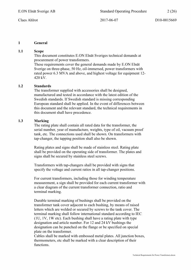
Unless otherwise specified short circuit power in the network shall at least be according to table 2.
Highest voltage for equipment (kV)
Short-circuit power (MVA)
24 800
36 1 00052, 72.5 and 82.5 3 000
145 10 000170 10 000245 17 000420 25 000
Table 2. Short circuit capability
Unless otherwise specified, the short-circuit impedance shall be selected according to the table3.
Table 3. Recommended standard ratings
For a three-winding transformer short circuit impedance between HV and MV, HV and LV shall be selected according to Table 3.MV and LV short circuit impedance shall be selected according to manufacturer’s suggestions.
Connection group & RatiosThe connection group and precise voltage ratio shall be specified in the project unique technical specification for the transformer.
Stabilizing winding (delta connected)All transformers with connection symbol Y/y shall be provided with a delta connected stabilizing winding. The stabilizing winding shall be
Rated power (MVA) 6.3 10 16 25 40 63 80 100
Rated voltage (kV)Primary side
Secondary side
Short-circuit impedance (%)
23 11.5 7 834.5 11.5 7 8 946 23 11.5 7 8 957.5 23 11.5 7 8 9 1077 23 11.5 8 9 10 10140 23 11.5 9 10 10 12 12 12140 57.5 46 10 12 12 12140 34.5 9 10 10 12 12 12

E.ON Elnät Sverige AB Standard Operating Procedure 7 (26)
Claes Ahlrot 2017-06-07 D10-0015669
Technical Requirements for Power Transformers.docm
performed with open delta connection via two bushings. Closing the delta and earthing shall be done on the transformer tank cover.
EarthingFor earthing of 145 kV transformers neutral and surge arresters in both neutral and phases for all voltages the transformer shall be provided with separate conductors insulated from the transformer tank. These conductors shall be linked together close to the bottom of the transformer tank. The surface of the conductor shall be bare metal or black. For directly earthed neutrals these conductors shall be connected directly to the neutral terminal.
For earthing of the transformer tank a plate shall be welded at two diametrically opposite points at the bottom of the transformer tank. The plate shall be provided with four holes, with a distance between centres of 40 mm vertically and 50 mm horizontally. The holes shall be 14 mm diameter. The surface shall be protected against corrosion and have good electrical conductivity.
All current transformer secondary terminals shall be brought down to a separate junction box, where every 3-phase group shall be connected by its own earth conductor to a common earthing point. A copper conductor with a cross-section area of at least 25 mm2 shall also be connected to this earthing point.
Power supply for motors and control equipmentEquipment shall be designed for a maximum permitted voltage variation between -15% to +10% in the connection point of the apparatus.
Auxiliary contacts/switchesThe rated current of the auxiliary contacts shall be at least 0.4 A at 110 V DC inductive circuit with a time constant of 40 ms.
Terminal blocksTerminal blocks for external cables shall be provided with open-circuiting facilities and 4 mm test outlets. The terminal board screw for securing the wire shall not be of the lift cage type.Jumpers between terminals shall be made with insertion bridge or similar on either the internal or external side.

E.ON Elnät Sverige AB Standard Operating Procedure 8 (26)
Claes Ahlrot 2017-06-07 D10-0015669
Technical Requirements for Power Transformers.docm
Power and control cablesShielded or wire-armoured cables shall be used.
The cable size shall be decided by the transformer supplier, although the cross-section area for the current transformers shall not be less than 2.5 mm2 and for other applications not less than 1.5 mm2.
3.1.1 On-load tap-changer and cooling equipmentFan and pump motors shall be designed for a 400 V, 3-phase, 50 Hz power supply. The control voltage shall be 230 V, 50 Hz. Failure of a fan to start shall be detectable by sensing the contactors. The equipment shall have degree of protection IP 54 according to SS-EN 60529.
The control voltage for the on-load tap-changer shall be 110 V DC. Unless otherwise specified, the drive motor shall be designed for 400 V AC, 3-phase, 50 Hz power supply.
For protection against condensation the OLTC drive mechanism shall be equipped with a permanently connected heater element provided with a guard to prevent inadvertent touching and designed for a 230 V, 50 Hz power supply.
3.1.2 Off-circuit tap-changerA connection plate under cover with bolted connections ±2x2.5 % shall be used.
If off-circuit tap-changer are requiered (ex mobile transformers) the off-circuit tap-changer shall have a switching range of ±2x2.5 %. The external parts shall be made of corrosion-free- and UV-resistant material. The switchgear shall have a secure position lock and the maneuverability not impaired by oxidation or bimetallic corrosion. Type and fabrication shall be stated in the tender by the supplier.
3.2 Mechanical requirements
3.2.1 Transformer tankGeneralThe tank shall be designed and manufactured to withstand full internal vacuum (vacuum-proof), and all welds shall be continuous welds. Pressure relief valves must not be fitted to the transformer.
BottomThe bottom of the transformer tank shall be flat and self-supporting.The transformer shall be designed for placement on two beams.
E.ON Elnät Sverige AB Standard Operating Procedure 9 (26)
Claes Ahlrot 2017-06-07 D10-0015669
Technical Requirements for Power Transformers.docm
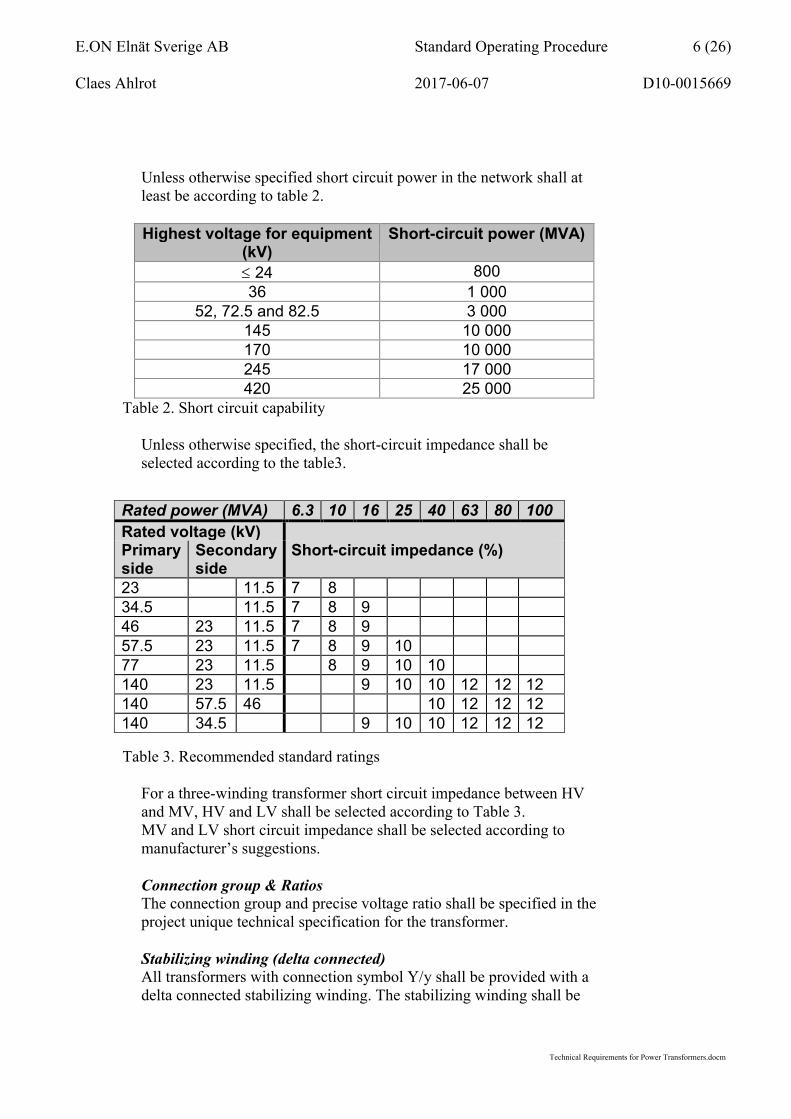
JacksThe tank shall be provided with clearly marked places to which jacks can be applied. The distance between the bottom of the tank and the jacking surface shall be between 300 and 350 mm. The size of the jacking surface shall not be less than 300 x 300 mm.
Tank coverThe transformer tank cover shall be welded to the transformer tank. Welding shall be done in such a manner that it will allow for simple opening of the tank in the future. Clear instructions for opening shall be included in the transformer documentation. The transformer tank cover shall be designed to prevent accumulation of water.
3.2.2 Valves and manhole coversSamplingTwo separate valves shall be provided for oil sampling at the bottom of the transformer tank for analysis of the bottom and top oil. The valves shall be clearly marked “Provtagning bottenolja” and “Provtagning toppolja”. The valve connections shall have R ¾” male threads.
Oil regenerationAll transformers shall be provided with two valves for connection to an oil treatment unit. The size shall at least be DN 80 with R 1 ½” male thread.
Manhole coversTransformers with immersed on-load tap-changers in the transformer tank shall be provided with manhole cover for possible future inspection of the contacts on the selector section of the tap-changer. The manhole cover shall be continuous welded.
3.2.3 Surface treatmentExternal surface treatmentThe transformer tank and the accessories fitted to it shall be surface treated according to corrosivity category C4 specified in SS-EN ISO 12944. The expected durability shall be high (H) > 15 years. Corrosion protection system shall be designation S4.22.
Internal treatmentThe inside of the transformer tank and conservator shall be degreased, shot blasted to at least surface cleanliness Sa 2 ½ according to SIS 05 59 00, blown clean and then painted.Painting shall be carried out with a varnish that does not cause elevated gas evolution in the oil or that has an otherwise detrimental effect on the performance of the transformer.

E.ON Elnät Sverige AB Standard Operating Procedure 10 (26)
Claes Ahlrot 2017-06-07 D10-0015669
Technical Requirements for Power Transformers.docm
Control cabinets, cooling radiators, brackets and screwsAll external components on the transformer shall be either hot-dip galvanized or made of stainless steel. Cooling radiators and brackets shall be hot-dip galvanized with a zinc coat thickness of at least 60 m, and shall not be painted. Control cabinets shall be of stainless steel or aluminium. Screws and bolts shall be of stainless steel.
3.2.4 Surge arrestersMechanical designThe surge arrester shall be designed to withstand static and dynamic forces in the direction that is most disadvantageous.
3.2.5 Junction boxes/control cubicles and cablesSeparate junction boxes for each purpose are preferable, although the supplier is free to connect the equipment to a common control cubicle, provided that distinct partitions clearly separate the various parts.
NOTE! Current transformers and any capacitive terminals shall alwaysbe wired to separate junction boxes.
Junction box 1. Supervisory equipment; Gas-actuated protective device (Buchholz relay)Oil level indicatorsThermometersPressure switch for tap-changer
Junction box 2. Secondary windings of the current transformers on the transformer primary sideJunction box 3. Secondary windings of the current transformers on the transformer secondary sideJunction box 4. Cooling equipment controls. This control cubicle shall be mounted on anti-vibration pads
Power and control cablesCables running on the transformer must not rest directly on the cover or the tank. Cables shall be protected against physical damage by sheet steel protection or effective armouring. However, the protection of the cables must not be located so that water run-off will be hampered.Clamps and straps shall be made of stainless steel.Cables shall enter the junction boxes from below or diagonally from below, so that water will be unable to run along the cable towards the seal.

E.ON Elnät Sverige AB Standard Operating Procedure 11 (26)
Claes Ahlrot 2017-06-07 D10-0015669
Technical Requirements for Power Transformers.docm
3.3 Other requirements
3.3.1 Oil and oil systemOilThe necessary quantity of transformer oil for commissioning the transformer shall be included in the delivery and safely stored with no chance for leakage to the surrounding. The oil shall be naphthene-based, inhibited with at least 0.3 % of anti-oxidant of di-tert butyl paracresol (DBPC) according to SS-EN 60296, class (03) classification “Special Applications Arctic High Grade”. Only oil that has been approved in writing by the Purchaser is acceptable.
The supplier shall submit an oil specification for the Purchaser’s approval. The specification shall clearly specify the principal base of the oil, the refining site and the country of origin.
Contents of PCB in the oil are strictly forbidden, down to lowest detectable ppm level of PCB.
Oil systemThe oil system of the transformer shall be separated from the surrounding with for example a rubber bag or another expansion system. If rubber bag is used it shall be air filled and have same temperature capability as the transformer. The filler opening on the conservator shall have a diameter of at least 150 mm, so that the sensor for the magnetic oil level indicator can be tested by activating it by hand, where applicable.
The connection between the conservator and the transformer tank shall be fitted with a shut-off valve, to enable the oil level in the tank to be lowered without the need for draining the oil from the conservator. In addition, the conservator of both the transformer and the on-load tap-changer shall be equipped with a drain valve at the bottom. Similarly, the on-load tap-changer shall be equipped with shut-off and drain valves for draining the tap-changer compartment.
The dehydrating breather shall be equipped with an oil trap through which the air drawn in must flow before it comes into contact with thedehydrating material. The quantity of dehydrating material shall consist of at least 0.5 litres Ambragel for each 1000 kg oil. The dehydrating breather shall be located a maximum of 1.2 metres from the bottom of the tank.
For transformers ≥100 MVA the dehydrating breathers shall be of maintenance free type.

E.ON Elnät Sverige AB Standard Operating Procedure 12 (26)
Claes Ahlrot 2017-06-07 D10-0015669
Technical Requirements for Power Transformers.docm
All pipes between conservator, transformer tank and dehydrating breathers shall be of steel. Rubber hose, flexible hose or other similar materials will not be accepted.
3.3.2 On-Load Tap-Changer (OLTC)On-load tap changing shall be carried out by means of a quick-switching tap-changer utilizing both local and remote control. The OLTC shall withstand the routine and type tests according to SS-EN 60214.
The OLTC shall be rated for at least the same current as the transformer winding. When over current flows through the OLTC, the drive motor shall stop. This shall be arranged by means of external breaking contacts in series with the control circuit in the drive mechanism. When the external breaking contacts re-close, i.e. when the over current has ceased, the operation shall be completed.
Diverter switch shall be vacuum type. The oil in the diverter switch compartment shall be totally separated from the oil in the transformer. This applies also for vacuum type diverter switches. The OLTCconservator shall be equipped with magnetic oil level indicator similar to the transformer conservator magnetic oil level indicator.
The OLTC shall be equipped with a pressure activated switch that is wired to the junction box for supervisory equipment.
The drive mechanism shall utilize electrical operation directly from controls inside the drive mechanism and from the control room. It shall also be possible to operate the OLTC by hand using a crank.
The drive mechanism shall be provided with an electrical extra limit position for interlocking of higher voltages on the transformersecondary side.
The motor circuit must not contain fuses located in the drivemechanism and the motor itself shall be protected against overload by a motor protective switch. The circuits for the motor, control and position indication shall be galvanically separated.
OLTC position shall be shown in the drive mechanism. Number of operations shall be recorded by a six-digit mechanical counter, readable from the outside. It shall not be possible to reset the counter.When the drive mechanism is not in the rest position, it shall be indicated, both mechanically and electrically.

E.ON Elnät Sverige AB Standard Operating Procedure 13 (26)
Claes Ahlrot 2017-06-07 D10-0015669
Technical Requirements for Power Transformers.docm
The drive mechanism shall be provided with distinct and durable marking with arrows for both operating directions when using the crank.Operation towards a higher tapping position shall correspond to a reduced ratio implying a higher voltage on the secondary side of the transformer.
An electrical operation that has been started shall be completed even if the duration of the control signal is shorter than the drive mechanism operating time.
End positions shall be equipped with contacts opening both motor and control circuits for relevant direction.
Following auxiliary contacts and functions shall be provided and clearly visible in documents and drawings:
One change-over contact activated as soon an operation is initiated and remains activated until the operation is finalized.
One auxiliary contact that is closed during switching of the primary current. The operation of this contact shall correspond as closely as possible to the critical switching time.
OLTC position shall be indicated by two analogue potentiometers with as many positions as the OLTC and OLTC minus one. Potentiometer one shall have 50 ohm/step and potentiometer two shall have 10 ohm/step.
3.3.3 BushingsBushings shall fulfill SS-EN 60137. For windings rated 52 kV and higher condenser (capacitor) bushings with capacitive taps shall be used. The taps shall be grounded.

E.ON Elnät Sverige AB Standard Operating Procedure 14 (26)
Claes Ahlrot 2017-06-07 D10-0015669
Technical Requirements for Power Transformers.docm
Bushing terminals shall be according table 4 if not otherwise specified.
Table 4. Bushing terminals
Bushings ≥52 kV shall be of dry type. All insulators shall be made ofsilicone rubber.
3.3.4 Current transformersTerminalsAll phase bushings with highest voltage for equipment ≥52kV shall be provided with current transformers. The current transformers shall be designed, manufactured and tested in accordance with SS-EN 60044.
For transformers ≥145 kV also the neutral bushing shall be provided with a current transformer. The ratio for the neutral current transformer shall be the same as for current transformers at phase bushings. The current transformer in the neutral shall have two protection cores and no metering core.
Current transformers shall be selected as follows:
Highest voltage for equipment(kV)
Rated power(MVA)
Ratio of metering core, 1 unit (A)
Ratio of protection cores, 2 units (A)
52 6,3 150/2 150/152 10 200/2 200/152 16 300/2 300/152 25 500/2 500/152 40 800/2 800/152 63 1200/2 1200/152 80 1500/2 1500/152 100 2000/2 2000/1Table 5. Current transformer ratings
Terminal Type of terminal Material≥52 kV
Phase and neutralCylindrical stud: Length 125 mm.
For rated currents < 1250 A 30 mm. ≥ 1250 A, max 2500A 60 mm.
Aluminum
36, 24 and 12 kV Phase and neutral
Vertical plate: Four holes for currents < 2500 A. Nine holes for currents ≥ 2500 A. Hole diameter
14 mm, c-c 40 mm.
Brass
E.ON Elnät Sverige AB Standard Operating Procedure 15 (26)
Claes Ahlrot 2017-06-07 D10-0015669
Technical Requirements for Power Transformers.docm
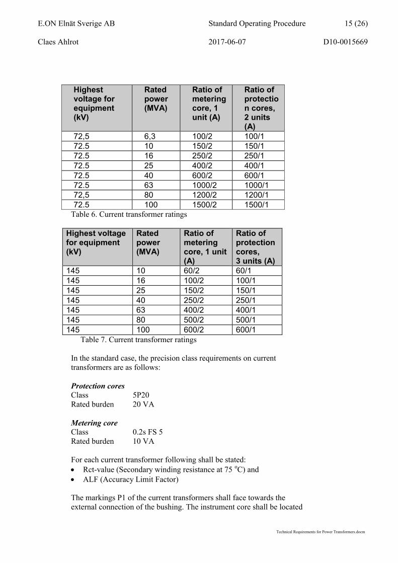
Highest voltage for equipment(kV)
Rated power(MVA)
Ratio of metering core, 1 unit (A)
Ratio of protection cores, 2 units (A)
72,5 6,3 100/2 100/172.5 10 150/2 150/172.5 16 250/2 250/172.5 25 400/2 400/172.5 40 600/2 600/172.5 63 1000/2 1000/172,5 80 1200/2 1200/172.5 100 1500/2 1500/1
Table 6. Current transformer ratings
Highest voltage for equipment(kV)
Rated power(MVA)
Ratio of metering core, 1 unit (A)
Ratio of protection cores,3 units (A)
145 10 60/2 60/1145 16 100/2 100/1145 25 150/2 150/1145 40 250/2 250/1145 63 400/2 400/1145 80 500/2 500/1145 100 600/2 600/1
Table 7. Current transformer ratings
In the standard case, the precision class requirements on current transformers are as follows:
Protection coresClass 5P20Rated burden 20 VA
Metering coreClass 0.2s FS 5Rated burden 10 VA
For each current transformer following shall be stated: Rct-value (Secondary winding resistance at 75 oC) and ALF (Accuracy Limit Factor)
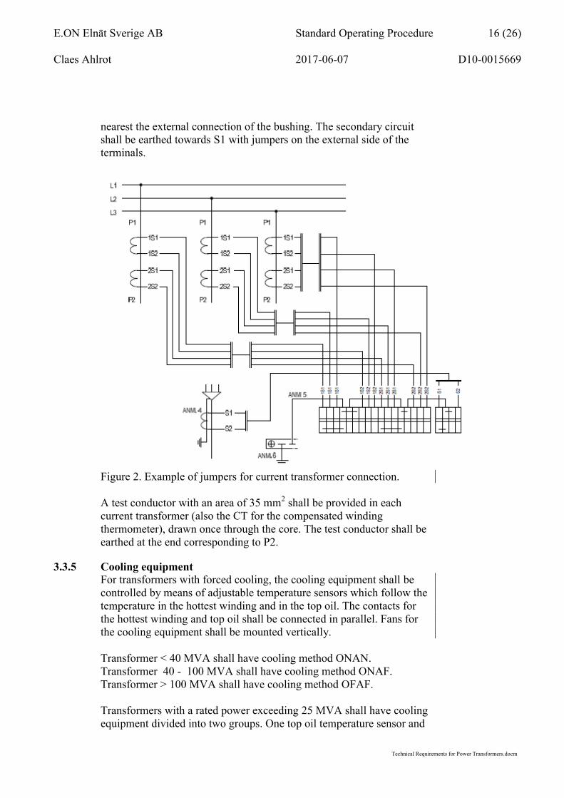
The markings P1 of the current transformers shall face towards the external connection of the bushing. The instrument core shall be located
E.ON Elnät Sverige AB Standard Operating Procedure 16 (26)
Claes Ahlrot 2017-06-07 D10-0015669
Technical Requirements for Power Transformers.docm
nearest the external connection of the bushing. The secondary circuit shall be earthed towards S1 with jumpers on the external side of the terminals.
Figure 2. Example of jumpers for current transformer connection.
A test conductor with an area of 35 mm2 shall be provided in each current transformer (also the CT for the compensated winding thermometer), drawn once through the core. The test conductor shall be earthed at the end corresponding to P2.
3.3.5 Cooling equipmentFor transformers with forced cooling, the cooling equipment shall be controlled by means of adjustable temperature sensors which follow the temperature in the hottest winding and in the top oil. The contacts for the hottest winding and top oil shall be connected in parallel. Fans for the cooling equipment shall be mounted vertically.
Transformer < 40 MVA shall have cooling method ONAN. Transformer 40 - 100 MVA shall have cooling method ONAF.Transformer > 100 MVA shall have cooling method OFAF.
Transformers with a rated power exceeding 25 MVA shall have cooling equipment divided into two groups. One top oil temperature sensor and

E.ON Elnät Sverige AB Standard Operating Procedure 17 (26)
Claes Ahlrot 2017-06-07 D10-0015669
Technical Requirements for Power Transformers.docm
two mutually independent winding temperature sensors shall be provided for control and supervision.
3.3.6 Surge arrestersSurge arresters shall be zinc oxide arresters and designed, manufactured and tested according to SS-EN 60099-4.Transformer ≤145 kV shall be provided with surge arresters for phase terminals and neutral. The surge arresters shall be mounted on the transformer.
The surge arrester shall have voltage ratings according to table 8:Highest voltage for
equipment (kV)Location of
surge arresterRated voltage
Ur (kV)145 Phase 120
” Neutral 8472.5 Phase 66
” Neutral 4252 Phase 54” Neutral 36
36 Phase 36
” Neutral 2424 Phase 26” Neutral 18
12 Phase 13” Neutral 10
Table 8. Surge arresters voltage ratings
Deviations from above shall be specified. Consoles for surge arresters shall always be included; also if no surge arresters are included in the delivery due to a special agreement.
The surge arrester housings shall be made of silicone rubber or proven polymer material.
Surge arresters with highest voltage for equipment 52 -145 kV shall be provided with insulated base.
Surger arresters terminals shall be vertical plate, hole diameter 14 mm, c-c 40 mm.
Rated discharge currentThe rated discharge current shall be at least 10 kA for highest voltage for equipment 145 kV.

E.ON Elnät Sverige AB Standard Operating Procedure 18 (26)
Claes Ahlrot 2017-06-07 D10-0015669
Technical Requirements for Power Transformers.docm
Line discharge classThe line discharge class shall be at least class 2.
Guaranteed max protective dataRated
voltage(kV)
Discharge current (kA)
Max residual/discharge voltage(kV/Ur)
Steep-front/FOW
1) 10 kA
Fast-front/ lightning 2)
10 kA
Slow-front/ switching 3)
0.5 kA
145 10 3.1 2.75 2.2
Table 9. Maximum residual/discharge voltages at current waves
1) Steep-front/FOW 1/(2-20) μs 2) Fast-front/lightning 8/20 μs 3) Slow-front/switching 30/60 μs
Short-circuit capabilityArrester with silicone rubber housing does not need to be equipped with pressure release device but shall however fulfill following short-circuit capability:
Rated voltage
(kV)
Short-circuit capability (kA, 0.2 s)
145 40
82.5 20
Table 10. Short-circuit capability
3.3.7 Auxiliary windingIf stated in the technical specification the transformer shall be equipped with an auxiliary delta connected winding.
The winding shall be capable of: supplying external loads at 3-phase 0,42 ±2x2,5 % kV rated voltage
and up to 500 kVA, rated power acting as a stabilizing winding
The supplier shall select rated voltage and rated power for this winding and propose a short circuit-proof solution that meets these requirements.
This auxiliary distribution transformer shall be selected according to its highest voltage for equipment and through calculations verified by the supplier. Fuses and winding terminals shall be provided with a single phase insulating enclosure of incombustible material, which also must

E.ON Elnät Sverige AB Standard Operating Procedure 19 (26)
Claes Ahlrot 2017-06-07 D10-0015669
Technical Requirements for Power Transformers.docm
withstand arcing. The equipment shall be enclosed in a cubicle with a hinged and bolted front cover.This cubicle shall be provided with a legible plate reading "Får endast öppnas i spänningslöst tillstånd" (Only to be opened when off circuit).
Maintenance works (fuse replacement for instance) must not interfere with main transformer operation.
3.3.8 Monitoring equipmentThe transformer shall be equipped with following equipment: Gas relay/Buchholz relay Oil level indicator transformer Oil level indicator OLTC Thermometer, top oil temperature Thermometer, winding temperature
Gas relay/Buchholz relayGas relay shall be provided with shut-off valves and a by-pass to enable replacement of the gas relay as quickly as possible. The valves shall have distinct position indication “ÖPPET” (open) and “STÄNGT” (closed).The gas relay shall be provided with two galvanically separated set of contacts with following functions:
Contacts that close in the event of slow gas production, intended for alarm.
Contacts that close in the event of a rapid oil flow or low oil level, intended for trip. Function for low oil level shall be possible to de-activate.
The gas relay shall have valves for sampling of the gas and for testing atthe gas relay.
Oil level indicatorThe magnetic oil level indicators shall visually present the oil level and be equipped with normally open contacts for high and low oil level. The float shall be accessible for testing of the oil level indicator.

E.ON Elnät Sverige AB Standard Operating Procedure 20 (26)
Claes Ahlrot 2017-06-07 D10-0015669
Technical Requirements for Power Transformers.docm
Thermometers/temperature instrumentsTransformers shall be provided with following thermometers and thermometer pockets:
Rated power (MVA)
Thermometer for Number of thermometer pockets
< 10 Top oil temperature 2 10 and
< 25Top oil temperature and hottest winding temperature
3
25 and< 40
Top oil temperature and hottest winding temperature
4
40 Top oil temperature and all winding temperatures
5
Table 11. Thermometers and thermometer pockets
Each thermometer/temperature instrument shall have four galvanically separated contacts. Thermometers/temperature instruments shall be installed using resilient mountings and be positioned on the operating side of the transformer, maximum 1.2 m from the bottom of the tank.Oil temperature and winding temperature instruments shall be furnished with analogue temperature output 4-20 mA.
Temperature action levels shall be set according to table below:
Top oil temperatureWinding
temperature
ONAN ONAF OFAF ONAF OFAF
C C C C C
Start of fan group 1 55 50 65 65Signal “no fan start” fan group 1, (only used when only one fan group are installed on the transformer)
57 52 67 67
Start of fan group 2 60 55 75 75
Signal “no fan start”, fan group 1 and 2
62 60 77 77
Signal ”top oil temperature”
85 85 75
Trip top oil temperature 95 95 85Signal ”winding temperature”
100 100
Trip winding temperature
110 110
Table 12. Temperature action levels

E.ON Elnät Sverige AB Standard Operating Procedure 21 (26)
Claes Ahlrot 2017-06-07 D10-0015669
Technical Requirements for Power Transformers.docm
3.3.9 Sound powerUnless otherwise specified in the enquiry documentation, the noise levels from the transformer may not, under any circumstances, exceed the following limit values of maximum sound power. This applies both with and without the cooling system in operation.
Table 13. Sound levels
3.3.10 Impact recorderDuring transport the transformer shall be equipped with an impact recorder to register g-forces in x-, y- and z-directions.
4 Functional requirementsOperating conditionsThe transformer shall be designed and verified for continuous operation at a rated power stated in the technical specification.
A transformer with ONAF cooling shall without fans be possible to load according to table 14 without exceeding permissible temperatures or temperature rises according to SS-EN 60076-2.
Rated power (MVA) Overall sound power level, dB(A)
6.3 6210 6516 6625 6840 7863 7980 80
100 81150 83200 84300 87500 90750 97

E.ON Elnät Sverige AB Standard Operating Procedure 22 (26)
Claes Ahlrot 2017-06-07 D10-0015669
Technical Requirements for Power Transformers.docm
Primary side
ONAN/ONAF
31.5/40 MVA
40/50 MVA
50/63 MVA
63/80 MVA
80/100 MVATable 14. ONAF/ONAN ratings
Secondary side
(for 3 windings)
ONAN/ONAF
10/12 MVA
12/16 MVA
16/20 MVA
20/25 MVA
31.5/40 MVA
40/50 MVA
50/63 MVA
63/80 MVATable 15. ONAF/ONAN secondary side ratings for 3 winding transformers
The transformer with accessories shall be possible to load up to at least 140% of rated load at an ambient temperature of -10 °C according to SS-EN 60076-7, Short-time emergency loading.
The transformer shall, without negative consequences, energized or not withstand a lowest average ambient temperature of -40 ºC during one hour.
Bushings, OLTC, DETC, CT´s and all other accessories shall be designed and chosen so that they can carry at least the highest current for respective ratio and/or the highest current for the winding during a time that is at least equal to the time for the corresponding winding.

E.ON Elnät Sverige AB Standard Operating Procedure 23 (26)
Claes Ahlrot 2017-06-07 D10-0015669
Technical Requirements for Power Transformers.docm
5 TestingTesting of the power transformer shall be performed as factory acceptance test on the manufacturer factory area. Following chapters describes the scope, steering standards and the purchaser requirements. The manufacturer shall at tender stage clearly describe what type of site acceptance test that will be performed before commissioning to secure that the transformer have arrived to site without any internal or external damages.
ScopeUnless otherwise specified, the transformer shall be subject to the following tests. At pre-delivery testing, a test programme shall be set up so that the testing will be carried out in the order listed below:
Measurement of winding resistance according to SS-EN 60076-1 Measurement of voltage ratio and check of phase displacement
according to SS-EN 60076-1 Measurement of zero-sequence impedances according to SS-EN
60076-1 Measurement of short-circuit impedance and load loss according to
SS-EN 60076-1 Temperature rise test according to SS-EN 60076-2 Lightning impulse test according to SS-EN 60076-3 (also for
transformers with highest voltage for equipment 72.5 kV or below) Separate source withstand voltage test according to SS-EN 60076-3 Short-duration induced AC withstand voltage test (ACSD)
according to SS-EN 60076-3 Measurement of no-load loss and no-load current according to SS-
EN 60076-1 Measurement of sound levels according to SS-EN 60076-10 Tests on on-load tap-changer according to SS-EN 60076-1 For transformers > 170 kV, chopped wave lightning impulse tests
are routine tests for all windings of the transformer. (IEC 60076-3, Cl 7.1).
StandardsUnless otherwise specified, testing shall follow the scope and requirements on test results specified in the relevant SS-EN standard. However, if there are conflicting interpretations between Swedish and international standards, the Swedish standard have precedence.
RequirementsPDInduced voltage test with simultaneous partial discharge measurementshall be performed according to SS-EN 60076-3.

E.ON Elnät Sverige AB Standard Operating Procedure 24 (26)
Claes Ahlrot 2017-06-07 D10-0015669
Technical Requirements for Power Transformers.docm
Lightning impulseUnless otherwise stated in the specification, a lightning impulse voltage test (1.2/50 s) shall be performed on all transformers in accordance with the latest revision of the SS-EN standard. All phase bushings shall be tested directly, while the neutral point shall preferably be tested indirectly via the phase bushings with a 1.2/50 surge. The impulse level shall then be measured over an impedance between the neutral point and earth. However, if the neutral point is fully insulated (uniform insulation) or if, for some other reason, an indirect test cannot be carried out at the neutral bushing, a direct surge may be applied.
When testing the phases, the position of the on-load tap-changer shall be changed as the test proceeds. Example: Phase U is tested in the minimum position of the tap-changerPhase V is tested in the principal position of the tap-changer and Phase W in the maximum position of the tap-changer. If a direct surge at the neutral point is applied during surge voltage testing, the position of the tap-changer shall be selected in consultation between the supplier and E.ON Elnät Sverige AB.
Current transformers (CT)Current transformers shall be tested individually on place in the transformer during transformer factory acceptance test to an extent that verifies CT installation. Tests shall also be performed according to following table, but might be performed in separate test bench with a conductor with same dimension and location at current transformer as the one located at transformer. A test report shall be established including at least following tests.
Table 16. Tests for Current transformers
Measured values shown in test report shall be according to international (SI) System of Units.
SoundSound level measurement shall be carried out on all transformers, unless otherwise stated in the specification. The measurement method, background noise and the frequency spectrum of the sound emitted
Tested at Indicated test result
Current dependence 1, 5, 20, 100 and 120% of In Current failure (%), angle failure (min)
Burden dependence 1 VA, 25 and 100% rated burden at above % of In
Current failure (%), angle failure (min)
Accuracy limit factor Type test or routine test Constants a and b

E.ON Elnät Sverige AB Standard Operating Procedure 25 (26)
Claes Ahlrot 2017-06-07 D10-0015669
Technical Requirements for Power Transformers.docm
shall be shown in the test report. The measurement shall be carried out according to SS-EN 60076-10.
Zero-sequence impedanceMeasurement of zero-sequence impedance shall be carried out for y-and z-connected windings in principal position of tap-changer and both extreme positions. For transformers with reconnectable windings, e.g. 10-20 kV, measurement shall be carried out for both (all) connections.For each y- and z-connected winding in the transformer shall the imaginary- (X0) and real part (R0) of the zero-sequence impedance bedetermined. For transformers with a design that result in a non-linearimpedance shall the current dependence of the zero-sequence be recorded with measurements for at least four different current levels, to have a picture of the impedance current dependence obtained. Applied voltage, recorded current, phase angle and impedance value shall be shown in the test report. Impedance value shall be assigned in ohm per phase.
Gas analysis (DGA)The transformer oil shall be sampled before, during and after the temperature rise test in order to analyse the level and occurrence of the different gases. The results shall be shown in the test report.After final assembly at site, an oil sample shall be taken and sent to E.ON Elnät Sverige AB's framework contract laboratory.
Capacitive total current bushing terminalAt rated voltage and short circuit between a voltage terminal and earth, at least the following capacitive total current shall be obtained from the three phases:
Rated voltage (kV)
Capacitive current (mA)
140/3 10
77/3 8
57,5/3 7
46/3 6
Table 17. Capacitive current
6 DocumentationAll dimensional drawings, signal- and wiring diagrams shall be in A3 format. Disposition of terminals and marking/labelling shall be clearly included on drawings and wiring diagrams etc. The documentation shall be submitted on paper, as dwg files and as pdf files.

E.ON Elnät Sverige AB Standard Operating Procedure 26 (26)
Claes Ahlrot 2017-06-07 D10-0015669
Technical Requirements for Power Transformers.docm
The dimensional drawings shall include type of accessories, manufacturer and accessory drawing number. Material in primary terminals, transformer weight and outer dimensions shall be clearly specified in the dimensional drawings. Main data shall at least include rated power, rated voltage and connection group.
A transport drawing shall be included. The transport drawing shall include centre of gravity, positioning of hydraulic jacks, usable wagons and weights.
ScopeDocuments for review and approval during execution of the project: Rating plate Dimensional drawings and list of accessories Transport and installation drawings Circuit diagrams, list of apparatus, list of cables, lay-out drawings
for cubicles and control equipment Inspection and test program E.ON:s form for technical data
Final documentation shall be delivered 5 days after FAT and shall besubmitted in dwg- and pdf format and in paper (one copy in binder)including at least following documents: Rating plate Dimensional drawings and list of accessories Transport and installation drawings Circuit diagrams, list of apparatus, list of cables, lay-out drawings
for cubicles and control equipment Product data sheet for the oil Pictures of the active part four different sides Test protocolls and test results Instructions for maintenance and operation Assembly instructions Instruction for touch-up panting List of gaskets with dimensions and material included Instruction for opening of welded cover. Power transformer datasheet E.ON:s form for documentation data
![Standard Operating Procedure (SOP) FINAL Operating Procedure...Microsoft PowerPoint - Standard Operating Procedure (SOP) FINAL [Compatibility Mode] Author hp Created Date 4/23/2020](https://static.fdocuments.net/doc/165x107/60d7200d311d04701278f223/standard-operating-procedure-sop-operating-procedure-microsoft-powerpoint-.jpg)