Standard - L. Thorn Company · Welcome This guide is intended to illustrate design and construction...
48
Standard www.versa-lok.com Design & Installation Guidelines
-
Upload
truongtruc -
Category
Documents
-
view
215 -
download
0
Transcript of Standard - L. Thorn Company · Welcome This guide is intended to illustrate design and construction...

Standard
www.versa-lok.com
Design & Installation Guidelines

Welcome
This guide is intended to illustrate design and
construction capabilities of the VERSA-LOK®
Standard Retaining Wall System. There are
many variables to consider, however, when
planning or constructing any segmental retaining
wall. Soil types, drainage, loading, topography
and height need to be addressed on every project
to ensure safe, trouble-free installation.
Walls which support heavy loads or exceed 4
feet in height require special soil reinforcement
and often professionally designed plans.
Consult a qualified engineer if you are unsure
about any construction, site or soil conditions.
VERSA-LOK offers a variety of technical support,
including in-house engineering assistance and
reference literature. Please call 800-770-4525
with questions or to request the following:
You also can download Technical Bulletins,
product specifications and details from the
VERSA-LOK website at www.versa-lok.com.
• Technical Bulletin #1 Shoreline, Waterway and Retention Pond Protection
• Technical Bulletin #2 Stairs
• Technical Bulletin #3 Curves and Corners
• Technical Bulletin #4 Caps
• Technical Bulletin #5 Base Installation
• Technical Bulletin #6 Freestanding Walls, Columns and Vertical Walls
• Technical Bulletin #7 Tiered Walls
• Technical Bulletin #8
Fences, Railings and Traffic Barriers
Also available from VERSA-LOK:
• Design and Installation Guidelines - VERSA-LOK Mosaic®
• Technical Documentation for
Versa-Grid® Soil Reinforcement
• VERSA-LOK Standard and Mosaic Construction Details CD-Rom containing specifications and drawings created with
AutoCAD® software
AutoCad is a registered trademark of Autodesk, Inc.
VERSA-LOK StAndARd dESign And inStALLAtiOn guidELinES1
Welcome tothe VERSA-LOK
StandardRetaining Wall
System Designand Installation
Guidelines.

1 Introduction & Unit Specifications
2 System Overview
3 Wall Components• Typical Section• Foundation• Embedment• Soils and Compaction• Drainage Within Walls• Surface Drainage• Geosynthetic Reinforcement
4 Engineering
5 Special Design Considerations• Shorelines• Loads Behind Walls• Slopes• Tiering
6 Planning, Estimating & Final Designs
7 Wall Construction• Tools• Unit Modification• Excavation• Leveling Pad• Base Course• Additional Courses• Drainage Materials• Compacted Soil Backfill• Geosynthetic Soil Reinforcement• Caps
8 Basic Wall Design Elements• Curves• Corners• Stepped Base• Stepped Wall Top• Returns
9 Advanced Wall Features• Stairs• Freestanding Walls• Columns• Guardrails, Railings and Traffic Barriers
SUPPLEMENTAL INFORMATIONMaterial Estimation WorksheetVERSA-Grid® Estimation ChartsVERSA-LOK Standard SpecificationsVERSA-LOK Standard Construction Detail Drawings
3
5
6
11
13
15
16
25
29
3132
33-3940-46
Table of Contents
2VERSA-LOK StAndARd dESign And inStALLAtiOn guidELinES
This guide demonstrates the exceptional design capabilities and easy installation methods of the VERSA-LOK Standard Retaining Wall System.

Introduction & Unit Specifications
The VERSA-LOK Standard Retaining Wall
System is a permanent, attractive, preferred
alternative to ordinary retaining wall types.
Standard walls display a natural split-face
texture to complement any environment and,
because they are made of concrete, are
environmentally safe.
VERSA-LOK Standard retaining walls are
economically installed without mortar and do
not require concrete footings. In addition, one
Standard unit is used to build straight walls,
inside corners, outside corners, curves and
stairs. No special units need to be ordered
or estimated. Matching concrete caps are
available to attractively finish any VERSA-LOK
Standard wall.
The VERSA-LOK Standard System has earned
widespread approval from architects, engineers
and contractors. It provides unlimited design
flexibility, unsurpassed durability and fast
installation. The VERSA-LOK Standard system
may be easily installed by contractors, grounds
maintenance personnel or municipal
construction crews.
VERSA-LOK Standard retaining wall units are
ideal for residential, commercial and agency
projects. They are routinely used by many
state transportation departments and the
U.S. Army Corps of Engineers. Properly
designed, Standard walls may be constructed
to heights in excess of 50 feet.
VERSA-LOK Standard solid retaining wall units
are made from high-strength, low-absorption
concrete on standard block machines.
Solid characteristics make Standard
units resistant to damage before, during
and after construction in all climates.
Holes and slots molded into units accept
VERSA-TUFF® Pins, which are non-corrosive,
glass-reinforced nylon pins. Pins interlock
units and help provide consistent alignment.
This unique hole-to-slot pinning system permits
easy variable-bond construction—keeping
vertical joints tight.
VERSA-LOK StAndARd dESign And inStALLAtiOn guidELinES3
1
VERSA-LOK®
Standard units canbe used to buildwalls in excessof 50 ft. when
using appropriategeosynthetic
reinforcement andproper design.

4VERSA-LOK StAndARd dESign And inStALLAtiOn guidELinES
Introduction & Unit Specifications 1VERSA-LOK STANDARD UNITS(Actual unit size and weight may vary slightly by region.)
Standard units are made from high-strength, low-absorption concrete on concrete block machines.
The Standard units’ solid characteristics make them resistant to damage before, during and after
construction in all climates, including shoreline applications.Solid VERSA-LOKStandardunits providesuperiordurability andconstructionstability.
Height: 6 inches 152.4 mm
Width (face): 16 inches 406.4 mm
Width (rear): 14 inches 355.6 mm
Depth: 12 inches 304.8 mm
Face Area: 2/3 ft2 0.062 m2
Volume: .63 ft3 0.018 m3
Weight: 82 ibs. 37.19 kg
Wgt/Face Area: 123 ibs./ft2 599.84 kg/m2
VERSA-TUFF® PINLength: 6.8 inches 172.7mm
Diameter: .48 inches 12.2 mm
Material: glass-Reinforced nylon
VERSA-LOK CAP UNITSHeight: 3-5/8 inches 92.1 mm
Width (face): 14 inches 355.6 mm
Width (rear): A Cap 12 inches 304.8 mm
B Cap 16 inches 406.4 mm
Depth: 12 inches 304.8 mm
Weight: A Cap 40 lbs. 18.14 kg
B Cap 50 lbs. 22.68 kg

VERSA-LOK® Standard System Overview
PinningVERSA-LOK Standard
units interlock with non-
corrosive VERSA-TUFF®
Pins (two per unit). As
wall courses are installed,
pins are inserted through
holes in uppermost course
units and are received in
slots of adjacent lower course units.
Pinning helps to align units in a
consistent 3/4-inch setback per course.
Unreinforced WallsOn many projects, VERSA-LOK Standard
retaining walls work purely as gravity systems;
unit weight alone provides resistance to earth
pressures. Frictional forces between units and
pin connections hold units together so walls
behave as coherent structures. Batter setback
of wall faces offers additional resistance
against overturning.
Maximum allowable wall height for gravity
walls varies with soil and loading conditions.
Generally, with level backfill, good soils and no
excessive loading, VERSA-LOK Standard gravity
walls are stable to heights of 4 feet.
Reinforced WallsWhen weight of units alone is not enough
to resist soil loads, horizontal layers of geosyn-
thetics are used to reinforce soil behind walls.
With proper soil reinforcement and design,
VERSA-LOK Standard walls can be constructed
to heights in excess of 50 feet. Geosynthetics
do not act as tie-backs for wall faces. Rather,
geosynthetics and soil combine to create
reinforced soil structures that are strong and
massive enough to resist forces exerted on them.
In soil-reinforced walls, Standard units simply
retain soil between layers of geosynthetics and
provide attractive, durable faces.
Refer to next page
VERSA-LOK StAndARd dESign And inStALLAtiOn guidELinES5
2
VERSA-LOKStandard unitshave a unique
hole-to-slotpinning system
for easy installationand superior
structural integrity.

6VERSA-LOK StAndARd dESign And inStALLAtiOn guidELinES
VERSA-LOK® Standard Wall Components 3Reinforced Wall Typical SectionThis cross section illustrates typical components of VERSA-LOK Standard retaining walls. Mortarless
Standard walls are installed on granular leveling pads and do not require concrete footings below
frost. The amount and layout of drainage materials and geosynthetic soil reinforcement is site/soil
dependent and should be designed by a qualified engineer. The 3/4-inch setback of each unit creates a
cant of approximately 7 degrees. Canted walls are structurally more stable than vertical walls because
gravitational forces “pull” walls into retained soil.

VERSA-LOK® Standard Wall Components
FoundationFoundation soils upon which segmental retaining
walls will rest must be stiff, firm, and have
sufficient capacity to support wall system
weight. Any loose, soft or compressible material
must be removed and replaced with properly
compacted backfill. The bearing capacity of
the foundation soils should be addressed by
a soils engineer.
VERSA-LOK Standard retaining walls are
installed on leveling pads consisting of
coarse sand or well-graded angular gravel.
The most commonly used material for leveling
pads is that which is used locally as road base
aggregate. Granular leveling pads provide
stiff, yet somewhat flexible, bases to distribute
wall weights.
Rigid concrete footings extending below frost
are not required or recommended. Because
Standard units are installed without mortar,
they are free to move slightly in relation to each
other. Flexibility of the leveling pads and wall
units accommodates freeze/thaw cycles without
damage to structures. VERSA-LOK Standard
walls, installed on granular leveling pads, have
been successfully used on projects throughout
North America—including shoreline applications
and walls exceeding 50 feet in height.
Compacted granular leveling pads providea stiff but flexible base.
If a contractor chooses to form leveling pads
using concrete, unreinforced pads should be
made of lean concrete mix (200-300 psi) and no
more than 2 inches thick. To ensure correct
Standard unit alignment, special care needs to
be taken to construct concrete pads that are
exactly level. In rare situations where rigid,
reinforced-concrete footings are required, they
should be placed below seasonal frost depths.
VERSA-LOK StAndARd dESign And inStALLAtiOn guidELinES7
3
MortarlessVERSA-LOK
Standard retainingwalls do notrequire rigid
concrete footingsbelow frost.

8VERSA-LOK StAndARd dESign And inStALLAtiOn guidELinES
VERSA-LOK® Standard Wall Components 3EmbedmentVERSA-LOK Standard segmental retaining walls
usually have one-tenth of exposed wall heights
embedded below grade. For example, a wall
with 10 feet of height exposed above grade
would have a minimum of 1 foot buried below
grade—making a total wall height of 11 feet.
Embedment should be increased for special
conditions such as slope at the toe of walls,
soft foundation soils, or shoreline applications.
Embedment provides enhanced wall stability
and long-term protection for leveling pads.
Soils and CompactionWith proper design, segmental retaining walls
can be constructed within a wide variety of soil
conditions. Granular soils are preferred as fill
in the areas reinforced with geosynthetics;
however, fine-grained soils such as clays are
acceptable. Usually, coarse soils require less
soil reinforcement and are easier to compact
than fine soils. Problem materials like expansive
clays, compressible soils, or highly organic soils
(top soil) should be avoided or properly
addressed in designs.
Proper compaction of foundation and backfill soil
is critical to long-term performance of retaining
wall systems. Loose backfill will add pressure on
walls, collect water, cause settlement, and will
not anchor soil reinforcement materials properly.
Foundation and backfill materials should be
compacted to at least 95 percent of standard
Proctor density. (Proctor density is the maximum
density of the soil achieved in a laboratory
using a standard amount of compaction effort.)
Generally, construction observation and testing
for proper soil type and compaction is provided
by the project’s soils engineer.
Properlycompactedsoils are criticalto the performanceof a VERSA-LOKStandardretaining wall.
VERSA-LOK® Standard Wall Components
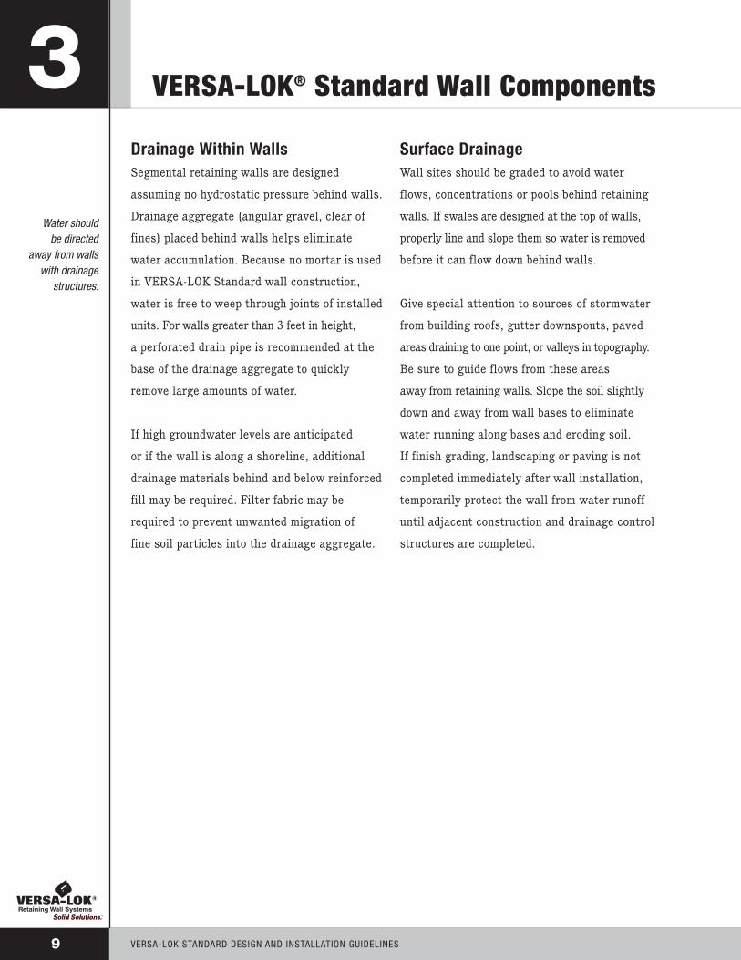
Drainage Within WallsSegmental retaining walls are designed
assuming no hydrostatic pressure behind walls.
Drainage aggregate (angular gravel, clear of
fines) placed behind walls helps eliminate
water accumulation. Because no mortar is used
in VERSA-LOK Standard wall construction,
water is free to weep through joints of installed
units. For walls greater than 3 feet in height,
a perforated drain pipe is recommended at the
base of the drainage aggregate to quickly
remove large amounts of water.
If high groundwater levels are anticipated
or if the wall is along a shoreline, additional
drainage materials behind and below reinforced
fill may be required. Filter fabric may be
required to prevent unwanted migration of
fine soil particles into the drainage aggregate.
Surface DrainageWall sites should be graded to avoid water
flows, concentrations or pools behind retaining
walls. If swales are designed at the top of walls,
properly line and slope them so water is removed
before it can flow down behind walls.
Give special attention to sources of stormwater
from building roofs, gutter downspouts, paved
areas draining to one point, or valleys in topography.
Be sure to guide flows from these areas
away from retaining walls. Slope the soil slightly
down and away from wall bases to eliminate
water running along bases and eroding soil.
If finish grading, landscaping or paving is not
completed immediately after wall installation,
temporarily protect the wall from water runoff
until adjacent construction and drainage control
structures are completed.
VERSA-LOK StAndARd dESign And inStALLAtiOn guidELinES9
3
Water shouldbe directed
away from wallswith drainage
structures.
10VERSA-LOK StAndARd dESign And inStALLAtiOn guidELinES
VERSA-LOK® Standard Wall Components 3
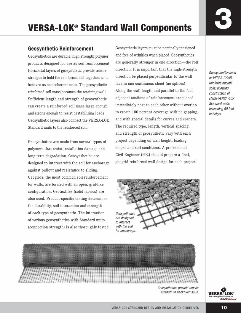
Geosynthetics suchas VERSA-Grid®reinforce backfillsoils, allowingconstruction ofstable VERSA-LOKStandard wallsexceeding 50 feetin height.
Geosynthetic ReinforcementGeosynthetics are durable, high-strength polymer
products designed for use as soil reinforcement.
Horizontal layers of geosynthetic provide tensile
strength to hold the reinforced soil together, so it
behaves as one coherent mass. The geosynthetic
reinforced soil mass becomes the retaining wall.
Sufficient length and strength of geosynthetic
can create a reinforced soil mass large enough
and strong enough to resist destabilizing loads.
Geosynthetic layers also connect the VERSA-LOK
Standard units to the reinforced soil.
Geosynthetics are made from several types of
polymers that resist installation damage and
long-term degradation. Geosynthetics are
designed to interact with the soil for anchorage
against pullout and resistance to sliding.
Geogrids, the most common soil reinforcement
for walls, are formed with an open, grid-like
configuration. Geotextiles (solid fabrics) are
also used. Product-specific testing determines
the durability, soil interaction and strength
of each type of geosynthetic. The interaction
of various geosynthetics with Standard units
(connection strength) is also thoroughly tested.
Geosynthetic layers must be nominally tensioned
and free of wrinkles when placed. Geosynthetics
are generally stronger in one direction—the roll
direction. It is important that the high-strength
direction be placed perpendicular to the wall
face in one continuous sheet (no splices).
Along the wall length and parallel to the face,
adjacent sections of reinforcement are placed
immediately next to each other without overlap
to create 100 percent coverage with no gapping,
and with special details for curves and corners.
The required type, length, vertical spacing,
and strength of geosynthetic vary with each
project depending on wall height, loading,
slopes and soil conditions. A professional
Civil Engineer (P.E.) should prepare a final,
geogrid-reinforced wall design for each project.
Geosyntheticsare designedto interactwith the soilfor anchorage.
Geosynthetics provide tensilestrength to backfilled soils.

Engineering
VERSA-LOK® Standard walls are designed as
traditional gravity walls. For unreinforced
walls, the stabilizing weight of the battered
wall units is compared to the loading on the
walls to ensure stability against overturning
and sliding (page 12, Figure 1A). When the
loading exceeds the stability of the units alone,
a larger gravity mass is created from reinforced
soil (page 12, Figure 1B).
Loading on segmental walls is dependent on soil
conditions, surcharges, slopes, water conditions
and wall heights. Accurate knowledge of each
of these properties is needed for a proper design.
Soil properties required for a segmental
retaining wall design include the internal fric-
tion angle (φ) and soil unit weight (γ). Gener-
ally, the cohesion (c) of any fine-grained soils is
conservatively ignored to simplify the design.
To ensure stability of a reinforced retaining
wall, the wall engineer must design the rein-
forced soil mass large enough to resist loads
from outside the wall system (external stability)
and with enough layers of proper strength
geosynthetic to keep the reinforced soil mass
together (internal stability). In addition, the
design must have sufficient geosynthetic layers
to keep units stable and properly connected to
the reinforced soil mass (facial stability).
For internal stability, the wall designer can
address potential overstress by using a higher
strength geogrid or adding more geogrid layers
by reducing vertical space between geogrid
layers. Potential pullout or internal sliding
concerns can be addressed by lengthening the
geogrid layers.
Internal compound stability is the potential
for compound failures starting directly behind
the wall, passing through the reinforced soil
mass and exiting out the front face of the wall.
The wall design engineer can address internal
compound stability by using a higher strength
geogrid type, adding geogrid layers, lengthen-
ing geogrid layers or improving the reinforced
soil type.
For facial stability, the wall design engineer can
address connection concerns by adding geogrid
layers (including shorter supplementary layers)
or using a higher connection strength geogrid.
For external stability, potential overturning
or sliding both can be addressed by lengthen-
ing the geogrid layers to create a larger, more
stable reinforced soil mass.
Evaluation of geotechnical concerns generally
is the responsibility of the soils engineer. How-
ever, in some cases, these can be addressed by
lengthening and strengthening the geogrid lay-
ers beyond what is required for the structural
wall design.
VERSA-LOK StAndARd dESign And inStALLAtiOn guidELinES11
4

Unreinforced Wall (Figure 1A) Reinforced Wall (Figure 1B)
Internal Stability
External Stability
Geotechnical Concerns
12VERSA-LOK StAndARd dESign And inStALLAtiOn guidELinES
Engineering 4
Pullout Breakage/Overstress
InternalSliding
Base Sliding Overturning
Global SlopeStability
Bearing/Settlement
Internal Compound

Special Design Considerations
ShorelinesVERSA-LOK® Standard retaining walls perform
well in shoreline applications. However, special
design considerations are often necessary to
ensure that water pressures do not build up
behind walls. Special provisions may include
granular reinforced backfill, additional drainage
aggregate, drainage behind reinforced soil masses
and filter fabric. Protection of bases from water
scour, wave action and ice may also be necessary.
See VERSA-LOK Technical Bulletin #1 for moreinformation on shorelines and retention pond protection. Loads Behind Walls
Surcharge loads behind walls can substantially
increase amounts of required soil reinforcement.
Common surcharge loads include parking areas,
driveways, roads and building structures. For
design purposes, permanent loads like buildings
are considered to contribute to both destabilizing
and stabilizing forces acting on walls. Dynamic
forces like vehicular traffic are considered to
contribute to destabilizing forces only.
Often, the highest surcharge loads are caused by
grading or paving equipment during construction.
Heavy equipment should be kept at least 3
feet behind the back of retaining wall units.
Soil reinforcement designs should accommodate
all anticipated surcharge loads—even if they
will occur infrequently or just once.
VERSA-LOK StAndARd dESign And inStALLAtiOn guidELinES13
5
With properdesign and
reinforcement,VERSA-LOK
Standard wallscan accommodate
special siteconditions suchas water loads,
slopes orsurcharges.

14VERSA-LOK StAndARd dESign And inStALLAtiOn guidELinES
Special Design Considerations 5
SlopesSlopes behind walls increase pressures,
sometimes doubling soil loads compared to
level backfills. Steep slopes below walls can
decrease stability of wall foundations. Slopes
can increase the amount of soil reinforcement
needed, especially the length. Generally, slopes
above or below walls should be no steeper
than 2:1 (horizontal:vertical).
TieringAesthetically, it may sometimes be desirable
to divide large grade changes into tiered wall
sections. However, upper wall tiers can add
surcharge loads to lower walls and necessitate
special designs. To avoid loading lower walls,
upper walls must be set back horizontally at
least twice the height of the lower walls.
If walls are placed closer, lower walls must
be designed to resist the load of upper walls.
Several closely spaced tiered walls can create steep,
unstable slopes. If tiered walls make a grade change
steeper than 2:1 (horizontal: vertical), global slope
stability may need to be reviewed by a qualified
soils engineer.
See VERSA-LOK® Technical Bulletin #7 for more
information on tiered wall construction.
When properlydesigned, tieredVERSA-LOK retainingwalls will not onlyretain soil andsupport loads,but will alsodeliver anattractiveappearance.

Planning, Estimating & Final Designs
PlanningPrior to design, accurate information needs to
be gathered, including soil conditions, proposed
wall heights, topography, groundwater levels
and surface water conditions. Proper permits,
owner approvals, utility clearances and
easements should also be obtained.
Make sure that layouts account for minimum
curve radii, wall setback, and area needed for
geosynthetic soil reinforcement. Be sure that all
wall components fit within property constraints.
Verify that temporary construction excavations
will not undermine foundation supports of any
existing structures or utilities. Considerations
should also be given to site access for equipment
and materials.
EstimatingAccurately estimate and order required
materials including VERSA-LOK Standard
units, VERSA-TUFF Pins, VERSA-LOK Cap
units, VERSA-LOK Concrete Adhesive, imported
backfill, leveling pad materials, geosynthetic soil
reinforcement and drainage materials. See the
Materials Estimation Worksheet on page 31 to
help determine VERSA-LOK product quantities.
For reinforced-wall projects, the VERSA-Grid®
estimating charts on page 32 provide approximate
amounts of geogrid soil reinforcement necessary
to construct walls in various soil and loading
conditions. For tall walls or complex situations,
VERSA-LOK staff engineers can prepare project
specific preliminary designs to be used for
estimation purposes.
Final DesignsFinal wall designs may be provided prior to
putting projects out for bidding. Alternatively,
projects can be specified design/build. With
design/build projects, the specifiers provide
wall layout information (line and grade) but not
final engineering for the wall. Contractors submit
bids based on this layout including estimated
labor, materials and final engineering costs.
Contractors who are awarded projects retain
licensed engineers to prepare final wall designs.
A soils report prepared by a qualified geotechnical
engineer is needed to provide information on
reinforced and retained properties. The soils
report should also address slope stability and
bearing capacity of foundation soils.
Design/build specifications and sample
construction details are provided on pages 33
to 46. This information, along with additional
details, is available in electronic format on
the VERSA-LOK Specifiers’ Binder CD or on the
VERSA-LOK website at www.versa-lok.com.
For walls more than 4 feet in height,
most building codes require a final wall design
prepared by a licensed Civil Engineer (P. E.)
registered in that state. VERSA-LOK and its
manufacturers have a network of licensed
civil engineers who are familiar with segmental
retaining wall design. These individuals are
available for referrals to architects, engineers
or contractors with final wall design needs.
VERSA-LOK StAndARd dESign And inStALLAtiOn guidELinES15
6
The VERSA-LOKtechnical staff is
available to assistin planning, layout,
estimating andreferrals for final
engineering.

16VERSA-LOK StAndARd dESign And inStALLAtiOn guidELinES
Wall Construction 7ToolsThe following tools may be helpful during
construction of VERSA-LOK Standard
Retaining Wall Systems.
VERSA-LIFTER®
Safety Protection
Shovel
4-Foot Level
Smaller Level
4-Pound Sledge Hammer
Masonry Chisel
Brick Hammer
Tape Measure
Hand Tamper
Vibratory-Plate Compactor
Caulking Gun
Stringline
Finishing Trowel
Broom
Diamond-Blade Concrete Saw
Hydraulic Splitter
Transit or Site Level
Backhoe or Skid-Steer Loader
The VERSA-Lifter makes it easier to lift and
place units—especially on the base course.
Two prongs on the lifter are inserted into pin
holes in each Standard unit. Lifting the handle
secures the lifter to the unit and makes for easy,
balanced lifting and placement.

VERSA-LOK® Standard Wall Construction
VERSA-LOK StAndARd dESign And inStALLAtiOn guidELinES17
7Unit ModificationDuring wall construction, it will sometimes be
necessary to split or cut VERSA-LOK Standard
units. Splitting will create attractive, textured
surfaces-similar in appearance to front faces of
units. Saw-cutting will produce smooth, straight
surfaces. In general, units are split when modi-
fied portions will be visible. Units are cut when
straight edges are required to fit closely next to
smooth edges of adjacent units.
SplittingTo split a
VERSA-LOK
Standard unit by hand, mark desired path of
split on unit top, bottom and back. Score along
the top and bottom paths using a 2- to 3-inch
masonry chisel and heavy hammer. Next,
place the unit on its face and strike along the
back path. It is easier to split units on the
ground than on a hard surface. Unit should
fracture nicely along paths. If many splits will
be required for a project, it may be helpful to
rent a mechanical or hydraulic splitter.
Saw-CuttingSaw-cuts are normally made using a gas-powered
cut-off saw with a diamond blade. To cut a
VERSA-LOK Standard unit, mark desired path of
cut on all unit sides. On a stable work surface,
place the unit face toward you with the top side
up, at a comfortable height. Make a straight cut
down and 2 to 3 inches into the face. Move
the saw to the top of unit, and cut through top
using successively deeper cuts. Flip unit over and
finish by cutting completely through the bottom of
the unit.
If a cut-off saw is not available, a common
circular saw and an inexpensive masonry blade
may be used. Cut 1 to 2 inches deep along
the path on the front face. Split the remainder of
the unit. The vertical cut on the face of the unit
will fit closely against adjacent units - the split
portion will not be visible.
VERSA-LOKStandard units areeasily modified by
splitting for atextured face,
or by saw-cuttingfor a smooth side.

18VERSA-LOK StAndARd dESign And inStALLAtiOn guidELinES
VERSA-LOK® Standard Wall Construction 7ExcavationExcavate just deep enough to accommodate the
leveling pad (usually 6 inches) and required
unit embedment below grade. When necessary,
also excavate areas where geosynthetic soil
reinforcement will be placed. Required unit
embedment varies with wall height and site
conditions. Generally, if grade in front of the
wall is level, one-tenth of the exposed wall
height should be buried (embedded) below
grade. Additional embedment may be required
for special conditions, including slopes in
front of walls, soft foundation soils and
water applications.
Compact soil at the bottom of excavation.
Do not place wall system on loose, soft, wet
or frozen soil—settlement may result. If the wall
will sit on previously backfilled excavations
such as utility line trenches, be sure the entire
depth of existing backfill is well-compacted.
If necessary, over-excavate soft soils and
replace with properly compacted backfill.
Leveling PadPlace granular leveling pad material and com-
pact to a smooth, level surface. Leveling pad
should be at least 6 inches thick and 24 inches
wide. It should consist of coarse-grained sand,
gravel, or crushed stone. Use a thin layer of fine
sand on top of the leveling pad for final leveling.
To quickly construct long
sections of leveling pad,
create forms by leveling
and staking rectangular
metal tubing along both
sides of the planned
pad. Place and compact
granular material within
these leveled forms and
screed off excess.
See VERSA-LOK Technical Bulletin #5 for more
tips about leveling pad construction.
If the planned grade along the wall front will
change elevation, the leveling pad may be stepped
in 6-inch increments to match the grade change.
Always start at the lowest level and work upward.
Step the leveling pad often enough to avoid
burying extra units while maintaining required
unit embedment.
Carefully planthe location andalignment of thewall base toensure top ofwall will be atdesired location.

VERSA-LOK® Standard Wall Construction
VERSA-LOK StAndARd dESign And inStALLAtiOn guidELinES19
7Base CourseMake sure that the leveling pad is level and
begin placing base course units. If the leveling
pad is stepped, begin at the lowest point and
place entire length of lowest course before
proceeding to next course.
Align units using their backs or slots rather than
their irregularly textured front faces. Stringlines
may be helpful when aligning straight walls.
Refer to pages 25, 26 and 27 for tips on curve
and corner alignment. Place units side by side
on the leveling pad. Front faces of adjacent units
should fit tightly and unit bottoms should contact
the leveling pad completely.
Using a 4-foot level, level units front to back,
side to side, and with adjacent units. Tap high
points with a mallet or hand tamper until level.
Take time to ensure a level base course. Minor
unevenness in the base course will be amplified
and difficult to correct after several courses have
been installed.
After base course has been positioned, place
and compact soil backfill behind the units.
Also replace and compact over-excavated soil in
front of units at this time. Backfill behind and in
front of embedded units should consist of soil—
do not use drainage aggregate.
Take time toensure a level base
course—minorunevenness in the
base course willbe amplified and
difficult to correctafter several
courses havebeen installed.

20VERSA-LOK StAndARd dESign And inStALLAtiOn guidELinES
VERSA-LOK® Standard Wall Construction 7Additional CoursesSweep off tops of installed units to remove any
debris that may interfere with additional courses.
Place next course so that the units are set back
3/4-inch from faces of installed units. Set the
units a short distance away from their final
position and slide them into place. Sliding
helps remove imperfections and debris from
the top surface of installed units.
The unique VERSA-LOK hole-to-slot pinning
system allows Standard units to be installed on
variable bond. (Units do not need to be placed
exactly halfway over the two lower course units.)
Vertical joints can wander in relation to other
joints throughout walls. However, units should
generally overlap adjacent lower course units
by at least 4 inches to aid structural stability.
Do not try to install walls on half bond by
leaving gaps in vertical face joints. Because
the bond can vary, vertical face joints can and
should be tight.
Insert two VERSA-TUFF® Pins through the front
holes of the upper-course units into the receiving
slots in the lower-course units. There are four
front holes in each unit, but only two are used.
Use the two outside holes when possible. If one
of the outside holes is not usable, move pin to
next closest hole. The two pins should engage
two separate units in the lower course. Make sure
the pins are fully seated in the lower unit slots.
If necessary, seat pins using a mallet and another
pin. Pins are fully seated when they are recessed
approximately 1 inch below the top surface of
upper units.
Pull the units forward to remove any looseness
in the pin connection. Check unit alignment and
levelness—adjust if necessary. If the length of a
course must fit into a limited space or if vertical
joints begin to line up with joints in the course
immediately below, adjust by installing partial
units. Create partial units by saw-cutting whole
units into pieces at least 4 inches wide at the
front face. When installing partial units, try to
disperse them throughout the wall. This technique
helps to hide partial units and lends to a more
attractive project.
Stack no more than three courses before
backfilling. If VERSA-LOK Standard units are
stacked too high, they may push out of alignment
during placement of backfill.
The unique holeto-slot pinningsystem allowsVERSA-LOKStandard unitsto be installedon variable bond.

VERSA-LOK® Standard Wall Construction
VERSA-LOK StAndARd dESign And inStALLAtiOn guidELinES21
7Drainage MaterialsBeginning at the level of planned grade in front
of the wall, place drainage aggregate (3/4-inch
clear, free-draining, angular gravel) between and
directly behind units to a minimum thickness of
12 inches. Drainage aggregate must be free of
fine dirt or soil. Do not place drainage aggregate
behind units that will be embedded. Drainage
aggregate is critical to wall performance because
it keeps water pressures from building up behind
the wall face.
For walls over 3 feet high, perforated drain
pipes should be used to collect water along
the base of the drainage aggregate. Drain pipes
help to quickly remove large amounts of water.
For some projects, often shoreline applications, a
geosynthetic filter fabric may be required behind
the drainage aggregate. Filter fabric will prevent
soils or sands (fines) from migrating into the
drainage aggregate and wall face joints.
Compacted Soil BackfillProper placement and compaction of backfill is
critical to the stability of a segmental wall.
Poorly compacted backfill puts extra pressures
on a wall—especially when it becomes wet.
Place soil backfill beginning directly behind
drainage fill in layers (lifts) no thicker than
6 inches. Compact soil backfill—making sure
that backfill is not too wet nor dry. The amount
and type of effort needed for adequate backfill
compaction varies with soil type and moisture
content. Generally, hand-operated vibratory-plate
compactors can be used to achieve adequate

22VERSA-LOK StAndARd dESign And inStALLAtiOn guidELinES
VERSA-LOK® Standard Wall Construction 7compaction of granular soils—even on big
projects. Fine soils such as clays should be
compacted with kneading-type equipment like
sheepsfoot rollers.
To avoid pushing wall units out of alignment,
do not use heavy self-propelled compaction
equipment within 3 feet of the wall face.
At the end of the day’s construction, protect the
wall and the reinforced backfill from possible
rainstorm water damage. Grade the soil backfill
so water will run away from wall face and direct
runoff from adjacent areas away from project site.
Geosynthetic Soil ReinforcementGeosynthetic soil reinforcement such as
VERSA-Grid® is used to reinforce soil backfill
when the weight of Standard units alone is not
enough to resist soil pressures. Soil reinforce-
ment type, length and vertical spacing will
vary for each project and should be specified
in a final wall design prepared by a licensed
Civil Engineer (P.E.).
Prepare to install soil reinforcement materials
by placing Standard units and backfilling
up to the height of the first soil reinforcement
layer specified on construction drawings.
Lay soil reinforcement horizontally on top
of compacted backfill and the Standard units.
Geosynthetic layers should be placed about
1 inch from the front of the Standard units.
Geosynthetics are usually stronger in one
direction. It is very important to place them in
the correct direction. The strongest direction
of the geosynthetic must be perpendicular to
the wall face. For correct orientation, follow the
geosynthetic manufacturer’s directions carefully.
After positioning soil reinforcement, place the
next course of Standard units on top of soil
reinforcement. Insert pins through Standard
units and into lower-course units. Place drainage
aggregate against back of the units and on top
of soil reinforcement. Remove slack by pulling
soil reinforcement away from the wall face and
anchoring at back ends. Beginning at the wall
The strongestdirection of thegeosynthetic(almost always theroll direction) mustbe perpendicularto the wall face.

VERSA-LOK® Standard Wall Construction
VERSA-LOK StAndARd dESign And inStALLAtiOn guidELinES23
7face, place and compact soil backfill. Keep
soil reinforcement taut and avoid wrinkles.
Place a minimum of 6 inches of soil backfill
before using any tracked equipment on top
of soil reinforcement. Follow manufacturer’s
construction guidelines to avoid damage to
soil reinforcement.
Placing soil reinforcement behind curves and
corners requires special layout and overlapping
procedures. Never overlap soil reinforcement
layers directly on top of each other. Slick surfaces
of geosynthetics will not hold in place properly
when placed directly on top of one another.
Always provide at least 3 inches of soil fill
between overlapping soil reinforcement layers.
While spacing of geogrid will vary, to ensure
stability during construction, vertical spacing
between geosynthetic layers should never
exceed 2 feet. See VERSA-Grid® estimating
charts on page 32 for assistance with preliminary
material estimating.
More, More, More...Continue placing additional courses, drainage
material, compacted soil backfill and geosyn-
thetic soil reinforcement as specified until
desired wall height is achieved. For walls more
than 4 feet high, most building codes require
a final wall design prepared by a licensed
Civil Engineer (P. E.) registered in that state.
VERSA-LOK and its manufacturers have a
network of licensed civil engineers who are
familiar with segmental retaining wall design.
These individuals are available for referrals
to architects, engineers, or contractors with
final wall design needs.
Proper backfillcompaction iscritical to thestability of a
segmentalretaining wall.

24VERSA-LOK StAndARd dESign And inStALLAtiOn guidELinES
VERSA-LOK® Standard Wall Construction 7CapsFinish the wall by placing cap units along
the top. Two VERSA-LOK Cap unit types are
available—A and B. Alternate A and B caps
on straight walls. Use A caps for convex
(outside) curves. Use B caps for concave
(inside) curves.
If cap layout does not exactly match the wall
radius, adjust spacing at the back of the caps
—do not gap caps at the front. To completely
eliminate gapping, it may be necessary to
saw-cut sides of cap units.
Front faces of caps may be placed flush, set
back, or slightly hung over faces of VERSA-LOK
Standard wall units. It is preferred to overhang
cap units approximately 3/4 inch to create an
“eyebrow” on top of the wall. Overhanging cap
units will create a small shadow on wall
units and help to hide minor imperfections
in wall alignment.
All cap units should be arranged before securing with
VERSA-LOK Concrete Adhesive. Secure caps by placing
two continuous 1/4-inch beads of adhesive along the top
course of wall units. Set caps on prepared wall units. Do
not secure caps using mortar or adhesives that become
rigid. A VERSA-LOK wall may move slightly (especially
in areas subject to freeze/thaw cycles), causing a rigid
cap adhesive to fail. Do not place caps if the units are too
wet for the adhesive to stick. In cold weather, keep the
adhesive tubes warm until just prior to use.
For more information about capping,
see VERSA-LOK Technical Bulletin #4.

Basic Wall Design Elements
VERSA-LOK StAndARd dESign And inStALLAtiOn guidELinES25
8CurvesThe trapezoidal shape of VERSA-LOK® Standard
units permits construction of concave, convex
and serpentine curves. General construction
requirements described earlier in this guide
(leveling pad preparation, drainage, compaction)
remain the same for curve installation. All radii
distances below are measured from circle centers
to front of unit faces.
Concave curves are constructed by increasing
spaces between backs of adjacent units—always
keeping front joints tightly aligned. Concave
curves may be built at any radius; however,
a minimum radius of 6 feet is recommended.
Radii smaller than 6 feet are structurally
adequate but tend to appear choppy.
Often, it is more appropriate to build
inside corners instead of tight
concave curves.
Convex curves are constructed by decreasing
spaces between backs of adjacent units. Because
upper courses of VERSA-LOK Standard units are
set back from lower courses by several inches,
course radii become smaller as walls become
taller. If a course radius becomes too small,
Standard units cannot be properly positioned
without cutting unit sides. Therefore, careful base
course planning for convex curves is important
when building tight curves.
Minimum top course radius for convex curves
is 8 feet. To calculate correct base course
radius, add 3/4 inch for each wall course to
the minimum radius. For example, minimum
base course radius for a wall that will have six
setbacks (including embedded units) will be
(6 x 3/4") + 8' = 8'+ 4-1/2".
See VERSA-LOK Technical Bulletin #3 for more
curve details, including proper placement of
geosynthetic soil reinforcement.
Inside Curve
Outside Curve
VERSA-LOKStandard is easilyinstalled in curves
without specialmodifications.

26VERSA-LOK StAndARd dESign And inStALLAtiOn guidELinES
Basic Wall Design Elements 8CornersVERSA-LOK® Standard units may be easily used
to create an unlimited variety of corners.
Outside 90-degree corner units are easily created
by splitting Standard units in half. Alternate
half units as shown above. This creates about
a 4-inch overlap of the units below. This is
acceptable - Standard units do not need to be
exactly halfway over the lower units (half-bond)
as explained on page 20.
Inside 90 Degree
Outside 90 Degree
Half units on outside 90-degree corners do
not pin. Instead, secure them using VERSA-
LOK Concrete Adhesive.
No unit modification is necessary to install
inside 90-degree corners. Place full-size
Standard units as shown, adjusting for
proper vertical joint arrangement.
See VERSA-LOK Technical Bulletin #3 for
more corner details, including proper placement
of geosynthetic reinforcement for corners.
The one Standardunit permitsconstruction of avariety of corners.
Basic Wall Design Elements
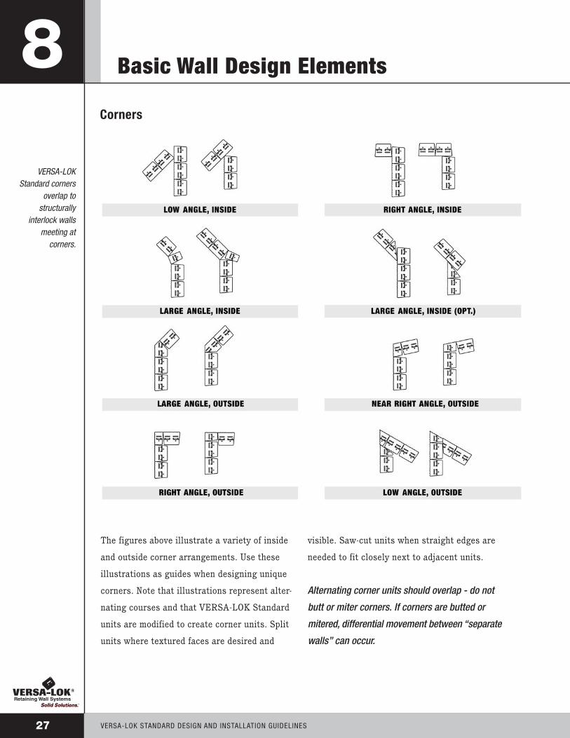
The figures above illustrate a variety of inside
and outside corner arrangements. Use these
illustrations as guides when designing unique
corners. Note that illustrations represent alter-
nating courses and that VERSA-LOK Standard
units are modified to create corner units. Split
units where textured faces are desired and
visible. Saw-cut units when straight edges are
needed to fit closely next to adjacent units.
Alternating corner units should overlap - do not
butt or miter corners. If corners are butted or
mitered, differential movement between “separate
walls” can occur.
VERSA-LOK StAndARd dESign And inStALLAtiOn guidELinES27
8Corners
VERSA-LOKStandard corners
overlap tostructurally
interlock wallsmeeting at
corners.

28VERSA-LOK StAndARd dESign And inStALLAtiOn guidELinES
Basic Wall Design Elements 8Stepped Base ElevationsIf the final grade along the front of the wall
changes elevation, the leveling pad and base
course may be stepped in 6-inch increments
to match the grade change. Always start at
the lowest level and work upward.
Step the leveling pad often enough to avoid
burying extra Standard units while maintaining
required unit embedment.
See VERSA-LOK® Technical Bulletin #5
for more information on stepped base and
wall-top installation.
Stepped Wall TopsWall tops should step to match grade changes.
As a wall steps down, use split half-units to
end each course. Split units provide textured
sides to match the wall face.
When capping tops of stepped walls, split the
exposed side of the last cap unit to create an
attractive end.
ReturnsAs an option to stepping wall tops, grade
changes at the top of a wall can be accommodated
by creating returns that turn into slopes behind
a wall.
Returns create a terraced appearance instead
of several small steps along the top of a wall.
The top ofVERSA-LOKStandard wallscan step down in6-inch incrementsor in larger stepscreated by returns.

Advanced Wall Features
VERSA-LOK StAndARd dESign And inStALLAtiOn guidELinES29
9
StairsStairs with a ratio 2:1 (horizontal:vertical) can
be easily installed using VERSA-LOK® Standard
units. Recommended step construction begins by
stacking a pedestal of Standard units. Cap units
are then placed as treads and vertical sidewalls
are installed.
See VERSA-LOK Technical Bulletin #2
for detailed stair installation instructions.
Freestanding WallsInstallers also can use Standard units to
create freestanding walls that are exposed on
both sides (walls that do not retain any soil).
Splitting units at the rear grooves, parallel to
the back of the units, creates textured faces
on the backs of the unit that match the front
split face. These modified units are arranged
to create a straight, vertical wall with textured
faces on both of the exposed sides of the wall.
For stability, freestanding walls should not
exceed 3 feet high.
See VERSA-LOK Technical Bulletin #6
for more information.
VERSA-LOK®
Standard unitswith VERSA-LOK
Caps as treadscan be used to
create a variety ofattractive stairs.
30VERSA-LOK StAndARd dESign And inStALLAtiOn guidELinES
Advanced Wall Features 9
ColumnsA wide variety of attractive columns can be
easily created from VERSA-LOK® Standard units.
Columns less than 4 feet high can be supported
on granular leveling pads with no frost footings,
just like VERSA-LOK Standard retaining walls.
The simplest column is created by splitting
Standard units into half-units and vertically
stacking them in a 20-inch by 20-inch square
column. However, columns of other sizes are
also possible with unit modification.
For stability, taller columns require cast-in-place
concrete footings. The center hole of the
columns (behind the units) can be used to
install steel-reinforced concrete to stabilize
taller columns. A qualified professional Civil
Engineer should provide a design for columns
over 4 feet high.
See VERSA-LOK Technical Bulletin #6
for more information.
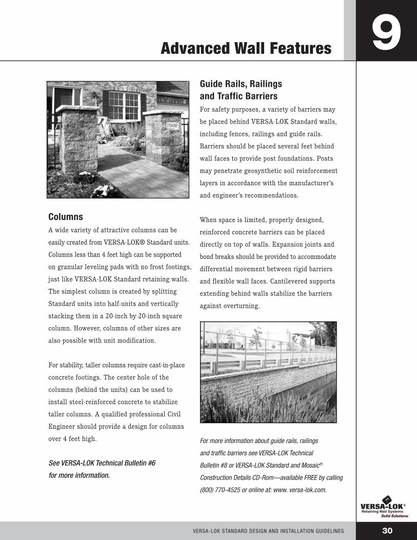
Guide Rails, Railingsand Traffic BarriersFor safety purposes, a variety of barriers may
be placed behind VERSA-LOK Standard walls,
including fences, railings and guide rails.
Barriers should be placed several feet behind
wall faces to provide post foundations. Posts
may penetrate geosynthetic soil reinforcement
layers in accordance with the manufacturer’s
and engineer’s recommendations.
When space is limited, properly designed,
reinforced concrete barriers can be placed
directly on top of walls. Expansion joints and
bond breaks should be provided to accommodate
differential movement between rigid barriers
and flexible wall faces. Cantilevered supports
extending behind walls stabilize the barriers
against overturning.
For more information about guide rails, railings
and traffic barriers see VERSA-LOK Technical
Bulletin #8 or VERSA-LOK Standard and Mosaic®
Construction Details CD-Rom—available FREE by calling
(800) 770-4525 or online at: www. versa-lok.com.

Material Estimation Worksheet
VERSA-LOK® Standard UnitsArea of Wall (SF) x 1.5 units per SF = number of Standard units
SF x 1.5 = units needed
VERSA-TUFF® Pinsunits x 2 Pins per unit = number of Pins
units x 2 = Pins needed
(Base course of VERSA-LOK Standard units does not require pins.)
VERSA-LOK CapsLineal Feet of Wall (LF) x .86 = number of Caps
LF x .86 = Caps needed
straight walls - use half A caps and half B caps
inside curves - use B caps
outside curves - use A caps
Additional caps may be needed for special splits or cuts.
Gradual curves may require a combination of A & B caps.
VERSA-LOK Concrete Adhesive11 oz. tube: LF ÷ 14 LF per tube = tubes
VERSA-Grid®
For estimating purposes, the tables on the following page provide
approximate amounts of VERSA-Grid soil reinforcement needed to
construct walls in certain soil and loading conditions. For tall walls
or complex situations, VERSA-LOK staff engineers can prepare project
specific preliminary designs to be used for estimation purposes.
VERSA-LOK StAndARd dESign And inStALLAtiOn guidELinES31

32VERSA-LOK StAndARd dESign And inStALLAtiOn guidELinES
VERSA Grid® Estimation Charts
these tables are provided for estimating purposes only they should not be usedor relied upon for any application without verification ot accuracy, suitability andapplicability for the use contemplated, which is the sole responsibility of the user. Afinal, project-specific design should be prepared by a qualified, licensed, professionalCivil Engineer (P.E.) based on actual site conditions. Preparation of these tables didnot include consideration or analysis of global slope stability or allowable bearingcapacity of foundation soils. these must be reviewed for each project by a qualifiedgeotechnical Engineer.
there are three tables provided in this guide to help estimate geogrid for differentwall loading situations - level backfill, sloping backfill and surcharges. to estimategeogrid quantities, first look under the column appropriate for project soils, determinethe height (H) of the proposed wall and read across the row (under appropriate soilcolumn) to approximate geogrid type, number of layers and lengths of each layer.
These design charts assumethe following conditions:
- uniform soil conditions
- Stable foundation soils
- Level grade in front of the wall
- no groundwater/water loads
- Slopes and loads behind
the wall as shown
- no additional loading behind
wall (such as tiered walls,
building loads, etc.)
Design standards and propertiesused to develop these charts were:
- design methodology in general
accordance with nCMA
design Manual for SRWs
- unit weight of soil (γ) 120 pcf
- internal friction angle of soil (φ)
as shown on charts
- Long-term design strength
of the geogrid (LtdS)
• VERSA-Grid VG 3.0 - 1250 Ib/ft
• VERSA-Grid VG 5.0 -1875 Ib/ft
*geogrids with similar LtdS and connection strengths to VERSA-LOK® units can also be estimated using these charts.With some variations, the VERSA-grid Vg 3.0 charts also generally estimate quantities for Miragrid 3Xt, Stratagrid 200,
and Raugrid 4/2. the charts for VERSA-grid Vg 5.0 generally estimate quantities for Miragrid 5Xt, Stratagrid 350, and Raugrid 6/3.
Miragrid is a registered trademark of Nicolon Corporation. • Stratagrid is a registered trademark of Strata Systems, Inc.Raugrid is a trademark of Luckenhaus Technische Textilien GmbH and Luckenhaus North America, Inc.
VERSA-GRID® Estimation Charts
VERSA-LOK STANDARD DESIGN AND INSTALLATION GUIDELINES 32
These tables are provided for estimating purposes only. They should not be used or relied upon for any application without verification of accuracy, suitability, and applicability for the use contemplated, which is the sole responsibility of the user. Afinal, project-specific design should be prepared by a qualified, licensed, professionalCivil Engineer (P. E.) based on actual site conditions. Preparation of these tables did not include consideration or analysis of global slope stability or allowable bearing capacity of foundation soils. These must be reviewed for each project by a qualifiedGeotechnical Engineer.
There are three tables provided in this guide to help estimate geogrid for different wall loading situations – level backfill, sloping backfill, and surcharges. To estimategeogrid quantities, first look under the column appropriate for project soils, determinethe height (H) of the proposed wall and read across the row (under appropriate soil column) to approximate geogrid type, number of layers, and lengths of each layer.
These design charts assume the following conditions:
- Uniform soil conditions
- Stable foundation soils
- Level grade in front of the wall
- No groundwater/water loads
- Slopes and loads behind the wall as shown
- No additional loading behind wall (such as tiered walls,
building loads, etc.)
Design standards and properties used to develop these charts were:
- Design methodology in general accordance with NCMA
Design Manual for SRWs
- Unit weight of soil (γ) 120 pcf
- Internal friction angle of soil (φ)as shown on charts
- Long term design strength of the geogrid (LTDS)
• VERSA-Grid VG 3.0 - 1250 lb/ft• VERSA-Grid VG 5.0 - 1875 lb/ft
*Geogrids with similar LTDS and connection strengths to VERSA-LOK® units can also be estimated using these charts.With some variations, the VERSA-Grid VG 3.0 charts also generally estimate quantities for Miragrid 3XT, Stratagrid 300,
and Raugrid 4/2. The charts for VERSA-Grid VG 5.0 generally estimate quantities for Miragrid 5XT, Stratagrid 500, and Raugrid 6/3.
Gravel (φ = 34°)
H (feet) D (feet) L (feet) layers VERSA-Grid
4 0.5 0 0 n/a
5 0.5 3.5 2 VG 3.0
6 0.5 4.0 2 VG 3.0
7 1.0 5.0 3 VG 3.0
8 1.0 5.5 4 VG 3.0
9 1.0 6.0 4 VG 3.0
10 1.0 6.5 5 VG 3.0
12 1.0 8.0 6 VG 3.0
Sand (φ = 30°)
H (feet) D (feet) L (feet) layers VERSA-Grid
4 0.5 4.0 1 VG 3.0
5 0.5 4.0 2 VG 3.0
6 0.5 4.5 2 VG 3.0
7 1.0 5.5 3 VG 3.0
8 1.0 6.0 4 VG 3.0
9 1.0 6.5 5 VG 3.0
10 1.0 7.0 5 VG 3.0
12 1.0 8.5 7 VG 3.0
Clay (φ = 28°)
H (feet) D (feet) L (feet) layers VERSA-Grid
4 0.5 4.0 1 VG 3.0
5 0.5 4.5 2 VG 3.0
6 0.5 5.0 2 VG 3.0
7 1.0 5.5 3 VG 3.0
8 1.0 6.0 4 VG 3.0
9 1.0 6.5 5 VG 3.0
10 1.0 7.0 6 VG 3.0
12 1.0 8.5 7 VG 3.0
Gravel (φ = 34°)
H (feet) D (feet) L (feet) layers VERSA-Grid
4 0.5 4.0 2 VG 3.0
5 0.5 4.5 2 VG 3.0
6 0.5 5.0 3 VG 3.0
7 1.0 6.0 4 VG 3.0
8 1.0 6.5 4 VG 3.0
9 1.0 7.0 5 VG 3.0
10 1.0 7.5 5 VG 3.0
12 1.0 9.0 7 VG 3.0
Sand (φ = 30°)
H (feet) D (feet) L (feet) layers VERSA-Grid
4 0.5 4.5 2 VG 3.0
5 0.5 5.5 2 VG 3.0
6 0.5 6.0 3 VG 3.0
7 1.0 7.0 4 VG 3.0
8 1.0 7.5 5 VG 3.0
9 1.0 8.5 5 VG 3.0
10 1.0 9.0 6 VG 3.0
12 1.0 10.0 7 VG 5.0
Clay (φ = 28°)
H (feet) D (feet) L (feet) layers VERSA-Grid
4 0.5 5.5 2 VG 3.0
5 0.5 6.0 2 VG 3.0
6 0.5 6.5 3 VG 3.0
7 1.0 7.5 4 VG 3.0
8 1.0 8.0 5 VG 3.0
9 1.0 9.0 5 VG 3.0
10 1.0 9.5 6 VG 3.0
12 1.0 11.0 7 VG 5.0
Gravel (φ = 34°)
H (feet) D (feet) L (feet) layers VERSA-Grid
4 0.5 4.0 1 VG 3.0
5 0.5 4.0 2 VG 3.0
6 0.5 4.5 3 VG 3.0
7 1.0 5.5 4 VG 3.0
8 1.0 6.0 4 VG 3.0
9 1.0 6.5 5 VG 3.0
10 1.0 7.5 6 VG 3.0
12 1.0 8.5 7 VG 3.0
Sand (φ = 30°)
H (feet) D (feet) L (feet) layers VERSA-Grid
4 0.5 4.5 1 VG 3.0
5 0.5 4.5 2 VG 3.0
6 0.5 5.5 3 VG 3.0
7 1.0 6.5 4 VG 3.0
8 1.0 7.0 5 VG 3.0
9 1.0 8.0 6 VG 3.0
10 1.0 8.5 6 VG 3.0
12 1.0 10.0 7 VG 5.0
Clay (φ = 28°)
H (feet) D (feet) L (feet) layers VERSA-Grid
4 0.5 4.5 2 VG 3.0
5 0.5 5.5 2 VG 3.0
6 0.5 6.0 3 VG 3.0
7 1.0 8.0 4 VG 3.0
8 1.0 9.5 5 VG 3.0
9 1.0 11.0 6 VG 3.0
10 1.0 12.0 6 VG 5.0
12 1.0 15.0 7 VG 5.0
250 psf
Miragrid is a registered trademark of Nicolon Corporation. • Stratagrid is a registered trademark of Strata Systems, Inc.Raugrid is a trademark of Lückenhaus Technische Textilien GmbH and Lückenhaus North America, Inc.
2' Max
H
D
L
H
D
L
H
D
L
2' Max
2' Max
Level Backfill
Sloping Backfill
Surcharge Backfill
STANDARD D&I GUIDE 2003 7/30/03 1:31 PM Page 33

VERSA-LOK® Specifications
PART 1: GENERAL
1.01 DESCRIPTION
A. Work includes furnishing and installing segmental
retaining wall (SRW) units to the lines and grades
designated on the project’s final construction drawings
or as directed by the Architect/Engineer. Also included
are furnishing and installing appurtenant materials
required for construction of the retaining wall as
shown on the construction drawings.
1.02 REFERENCE STANDARDS
A. Segmental Retaining Wall Units
1. ASTM C 1372
- Standard Specification for Segmental Retaining
Wall units
2. ASTM C 140
- Standard test Methods of Sampling and testing
Concrete Masonry units
B. Geosynthetic Reinforcement
1. ASTM D 4595
- tensile Properties of geotextiles
by the Wide-Width Strip Method
2. ASTM D 5262
- test Method for Evaluating
the unconfined Creep Behavior
of geosynthetics
3. GRI:GG1
- Single-Rib geogrid tensile Strength
4. GRI:GG5
- geogrid Pullout
C. Soils
1. ASTM D 698
- Moisture density Relationship
for Soils, Standard Method
2. ASTM D 422
- gradation of Soils
3. ASTM D 424
- Atterberg Limits of Soil
D. Drainage Pipe
1. ASTM D 3034
- Specification for Polyvinyl Chloride (PVC) Plastic Pipe
2. ASTM D 1248
- Specification for Corrugated Plastic Pipe
E. Engineering Design
1. “NCMA Design Manual for Segmental
Retaining Walls,” Second Edition
F. Where specifications and reference documents
conflict, the Architect/Engineer shall make the final
determination of applicable document.
1.03 SUBMITTALS
A. Material Submittals: The Contractor shall submit
manufacturers’ certifications two weeks prior to start of
work stating that the SRW units and geosynthetic
reinforcement meet the requirements of Section 2 of
this specification.
B. Design Submittal: The Contractor shall submit two
sets of detailed design calculations and final retaining
wall plans for approval at least two weeks prior to
the beginning of wall construction. All calculations and
drawings shall be prepared and sealed by a professional
Civil Engineer (P.E.) - (Wall Design Engineer)
experienced in SRW design and licensed in the state
where the wall is to be built.
1.04 DELIVERY, STORAGE AND HANDLING
A. Contractor shall check materials upon delivery to assure
that specified type and grade of materiais have been
received and proper color and texture of SRW units
have been received.
B. Contractor shall prevent excessive mud, wet concrete,
epoxies and like materiais that may affix themselves
from coming in contact with materials.
VERSA-LOK StAndARd dESign And inStALLAtiOn guidELinES33
34VERSA-LOK StAndARd dESign And inStALLAtiOn guidELinES
VERSA-LOK® Specifications
C. Contractor shall store and handle materials in
accordance with manufacturer’s recommendations.
D. Contractor shall protect materials from damage.
Damaged materials shall not be incorporated into
the retaining wall.
PART 2: MATERIALS
2.01 SEGMENTAL
RETAINING WALL UNITS
A. SRW units shall be machine-formed, Portland Cement
concrete blocks specifically designed for retaining
wall applications. SRW units currently approved for
this project are: VERSA-LOK Standard Retaining Wall
units as manufactured by .
B. Color of SRW units shall be .
C. Finish of SRW units shall be split-face.
D. SRW unit faces shall be of straight geometry.
E. SRW unit height shall be 6 inches.
F. SRW units (not including aggregate fill in unit voids)
shall provide a minimum weight of 105 psf wall face area.
G. SRW units shall be solid through the full depth of
the unit.
H. SRW units shall have a minimum depth (front face to
rear) to height ratio of 2:1.
I. SRW units shall be interlocked with connection pins,
designed with proper setback to provide 8:1 vertical to
horizontal batter (a 7-degree cant from vertical).
J. SRW units shall be capable of being erected with the
horizontal gap between adjacent units not exceeding
1/8 inch.
K. SRW units shall be capable of providing overlap of
units on each successive course so that walls meeting
at corner are interlocked and continuous. SRW units that
require corners to be mitered shall not be allowed.
L. SRW units shall be capable of providing a split-face,
textured surface for all vertical surfaces that will
be exposed after completion of wall, including any
exposed sides and backs of units.
M. SRW units shall be sound and free of cracks or other
defects that would interfere with the proper placing
of the unit or significantly impair the strength or
permanence of the structure. Cracking or excessive
chipping may be grounds for rejection. Units showing
cracks longer than 1/2" shall not be used within the
wall. Units showing chips visible at a distance of 30
feet from the wall shall not be used within the wall.
N. Concrete used to manufacture SRW units shall have a
minimum 28 days compressive strength of 3,000 psi
and a maximum moisture absorption rate, by weight,
of 8 percent as determined in accordance with ASTM
C140. Compressive strength test specimens shall con-
form to the saw-cut coupon provisions of ASTM C140.
O. SRW units’ molded dimensions shall not differ more
than ± 1/8 inch from that specified, in accordance with
ASTM C1372.
2.02 SEGMENTAL RETAINING
WALL UNIT CONNECTION PINS
A. SRW units shall be interlocked with VERSA-TUFF®
Pins. The pins shall consist of glass-reinforced
nylon made for the expressed use with the SRW
units supplied.
VERSA-LOK® Specifications
2.03 GEOSYNTHETIC REINFORCEMENT
A. Geosynthetic reinforcement shall consist of geogrids
or geotextiles manufactured as a soil reinforcement
element. The manufacturers/suppliers of the geosyn-
thetic reinforcement shall have demonstrated
construction of similar size and types of segmental
retaining walls on previous projects. The geosynthetic
type must be approved one week prior to bid opening.
Geosynthetic types currently approved for this project
are: VERSA-Grid® geogrids.
B. The type, strength and placement location of the
reinforcing geosynthetic shall be as determined by
the Wall Design Engineer, as shown on the final,
P.E.-sealed retaining wall plans.
2.04 LEVELING PAD
A. Material for leveling pad shall consist of compacted
sand, gravel or combination thereof (USCS soil types
GP, GW, SP, & SW) and shall be a minimum of 6
inches in depth. Lean concrete with a strength of 200
to 300 psi and 3 inches thick maximum may also
be used as a leveling pad material. The leveling pad
should extend laterally at least a distance of 6 inches
from the toe and heel of the lowermost SRW unit.
2.05 DRAINAGE AGGREGATE
A. Drainage aggregate shall be angular, clean stone or
granular fill meeting the following gradation as
determined in accordance with ASTM D422
SIEVE SIZE PERCENT PASSING
1 inch 100
3/4 inch 75-100
no. 4 0-60
no. 40 0-50
no. 200 0-5
2.06 DRAINAGE PIPE
A. The drainage collection pipe shall be a perforated or
slotted PVC, or corrugated HDPE pipe. The drainage
pipe may be wrapped with a geotextile to function as
a filter.
B. Drainage pipe shall be manufactured in accor-
dance with ASTM D 3034 and/or ASTM D 1248
2.07 REINFORCED (INFILL) SOIL
A. The reinforced soil material shall be free of debris.
Unless otherwise noted on the final, P.E. sealed
retaining wall plans prepared by the Wall Design
Engineer, the reinforced material shall consist of
the inorganic USCS soil types GP, GW, SW, SP, SM
meeting the following gradation, as determined in
accordance with ASTM D422:
SIEVE SIZE PERCENT PASSING 1 inch 100
no. 4 20-100
no. 40 0-60
no. 200 0-35
B. The maximum particle size of poorly-graded gravels
(GP) (no fines) should not exceed 3/4 inch unless
expressly approved by the Wall Design Engineer and
the long-term design strength (LTDS) of the geosyn-
thetic is reduced to account for additional installation
damage from particles larger than this maximum.
C. The plasticity of the fine fraction shall be less than 20.
VERSA-LOK StAndARd dESign And inStALLAtiOn guidELinES35

36VERSA-LOK StAndARd dESign And inStALLAtiOn guidELinES
VERSA-LOK® Specifications
PART 3: DESIGN PARAMETERS3.01 SOIL
A. The following soil parameters, as determined by the
Owner’s Geotechnical Engineer, shall be used for the
preparation of the final design:
unit internal Cohesion (c) Weight Friction
(γ) (pcf) Angle (φ) (degrees)
o
o
(If internal friction angles are not available for the above
section, the specifier can provide the USCS
soil type classification for the reinforced, retained
and foundation soils and/or attach the geotechnical
investigation report for this project.)
B. Should the actual soil conditions observed during
construction differ from those assumed for the design,
design shall be reviewed by the Wall Design Engineer
at the Owner’s Geotechnical Engineer’s direction.
3.02 DESIGN
A. The design analysis for the final, P.E.-sealed retaining
wall plans prepared by the Wall Design Engineer shall
consider the external stability against sliding and
overturning, internal stability, and facial stability of
the reinforced soil mass and shall be in accordance
with acceptable engineering practice and these specifi-
cations. The internal and external stability analysis shall
be performed in accordance with the “NCMA Design
Manual for Segmental Retaining Walls,” using the
recommended minimum factors of safety in this manual.
B. External stability analysis for bearing capacity, global
stability and total and differential settlement shall be
the responsibility of the Owner and the Owner’s
Geotechnical Engineer. Geotechnical Engineer shall
perform bearing capacity, settlement estimates and
global stability analysis based on the final wall design
provided by the Wall Design Engineer and coordinate
any required changes with Wall Design Engineer.
C. While vertical spacing between geogrid layers may
vary, it shall not exceed 2 feet maximum in the
wall design.
D. The geosynthetic placement in the wall design shall
have 100 percent continuous coverage parallel to the
wall face. Gapping between horizontally adjacent
layers of geosynthetic (partial coverage) will not
be allowed.
PART 4: CONSTRUCTION4.01 INSPECTION
A. The Owner or Owner’s Representative is responsible
for verifying that the contractor meets all the requirements
of the specification. This includes all submittals for
materials and design, qualifications and proper
installation of wall system.
B. Contractor’s field construction supervisor shall have
demonstrated experience and be qualified to direct all
work at the site.
4.02 EXCAVATION
A. Contractor shall excavate to the lines and grades
shown on the project grading plans. Contractor shall
take precautions to minimize over-excavation.
Over-excavation shall be filled with compacted infill
material, or as directed by the Engineer/Architect, at
the Contractor’s expense.
ReinforcedFill:
RetainedSoil:
FoundationSoil:

VERSA-LOK® Specifications
B. Contractor shall verify location of existing structures
and utilities prior to excavation. Contractor shall
ensure all surrounding structures are protected from
the effects of wall excavation. Excavation support, if
required, is the responsibility of the Contractor.
4.03 FOUNDATION PREPARATION
A. Following the excavation, the foundation soil shall be
examined by the Owner’s Engineer to assure actual
foundation soil strength meets or exceeds the assumed
design bearing strength. Soils not meeting the required
strength shall be removed and replaced with infill
soils, as directed by the Owner’s Engineer.
B. Foundation soil shall be proofrolled and compacted to
95 percent standard Proctor density and inspected by
the Owner’s Engineer prior to placement of leveling
pad materials.
4.04 LEVELING PAD CONSTRUCTION
A. Leveling pad shall be placed as shown on the final,
P.E.-sealed retaining wall plans with a minimum
thickness of 6 inches. The leveling pad should
extend laterally at least a distance of 6 inches from
the toe and heel of the lowest SRW unit.
B. Granular leveling pad material shall be compacted to
provide a firm, level bearing surface on which to place
the first course of units. Well-graded sand can be used
to smooth the top 1/4- to 1/2-inch of the leveling pad.
Compaction will be with mechanical plate compactors
to achieve 95 percent of maximum standard Proctor
density (ASTM D 698).
4.05 SRW UNIT INSTALLATION
A. All SRW units shall be installed at the proper elevation
and orientation as shown on the final, P.E.-sealed
retaining wall plans and details as directed by the
Wall Design Engineer. The SRW units shall be installed
in general accordance with the manufacturer’s
recommendations. The specifications and drawings
shall govern in any conflict between the two requirements.
B. First course of SRW units shall be placed on the leveling
pad. The units shall be leveled side-to-side, front-to-rear
and with adjacent units, and aligned to ensure intimate
contact with the leveling pad. The first course is
the most important to ensure accurate and acceptable
results. No gaps shall be left between the front of adja-
cent units. Alignment may be done by means of a string-
line or offset from baseline to the back of the units.
C. All excess debris shall be cleaned from top of
units and the next course of units installed on top
of the units below.
D. Two VERSA-TUFF Pins shall be inserted through
the pin holes of each upper course unit into
receiving slots in lower-course units. Pins shall be
fully seated in the pin slot below. Units shall be
pushed forward to remove any looseness in the
unit-to-unit connection.
E. Prior to placement of next course, the level and
alignment of the units shall be checked and corrected
where needed.
F. Layout of curves and corners shall be installed in
accordance with the wall plan details or in general
accordance with SRW manufacturer’s installation
guidelines. Walls meeting at corners shall be inter-
locked by overlapping successive courses.
G. Procedures C. through F. shall be repeated until
reaching top of wall, just below the height of the
cap units. Geosynthetic reinforcement, drainage
materials and reinforced backfill shall be placed in
sequence with unit installation as described in
Section 4.06, 4.07 and 4.08.
VERSA-LOK StAndARd dESign And inStALLAtiOn guidELinES37

38VERSA-LOK StAndARd dESign And inStALLAtiOn guidELinES
VERSA-LOK® Specifications
4.06 GEOSYNTHETIC REINFORCEMENT PLACEMENTA. All geosynthetic reinforcement shall be installed at the proper elevation and orientation as shown on the final, P.E.-sealed retaining wall plan profiles and details, or as directed by the Wall Design Engineer.
B. At the elevations shown on the final plans, (after the units, drainage material and backfill have been placed to this elevation) the geosynthetic reinforcement shall be laid horizontally on compacted infill and on top of the concrete SRW units. It shall be placed to within 1 inch of the front face of the unit below. Embedment of the geosynthetic in the SRW units shall be consistent with SRW manufacturer’s recommendations. Correct orientation of the geosynthetic reinforcement shall be verified by the Contractor to be in accordance with the geosynthetic manufacturer’s recommendations. The highest strength direction of the geosynthetic must be perpendicular to the wall face.
C. Geosynthetic reinforcement layers shall be one continuous piece for their entire embedment length. Splicing of the geosynthetic in the design strength direction (perpendicular to the wall face) shall not be permitted. Along the length of the wall (parallel to the face), horizontally adjacent sections of geosyn- thetic reinforcement shall be butted in a manner to assure 100 percent coverage parallel to the wall face.
D. Tracked construction equipment shall not be operated directly on the geosynthetic reinforcement. A minimum of 6 inches of backfill is required prior to operation of tracked vehicles over the geosynthetic. Turning should be kept to a minimum. Rubber-tired equipment may pass over the geosynthetic reinforcement at slow speeds (less than five miles per hour).
E. The geosynthetic reinforcement shall be free of wrinkles prior to placement of soil fill. The nominal tension shall be applied to the reinforcement and secured in place with staples, stakes or by hand tensioning until reinforcement is covered by 6 inches of fill.
4.07 DRAINAGE MATERIALSA. Drainage aggregate shall be installed to the line, grades and sections shown on the final P.E.-sealed retaining wall plans. Drainage aggregate shall be placed to the minimum thickness shown on the construction plans between and behind units (a minimum of 1 cubic foot for each exposed square foot of wall face unless otherwise noted on the final wall plans).
B. Drainage collection pipes shall be installed to maintain gravity flow of water to outside the reinforced soil zone. The drainage collection pipe shall daylight into a storm sewer manhole or along a slope at an elevation lower than the lowest point of the pipe within the aggregate drain.
4.08 BACKFILL PLACEMENTA. The reinforced backfill shall be placed as shown in the final wall plans in the maximum compacted lift thickness of 10 inches and shall be compacted to a minimum of 95 percent of standard Proctor density (ASTM D 698) at a moisture content within 2 percent of optimum. The backfill shall be placed and spread in such a manner as to eliminate wrinkles or movement of the geosynthetic reinforcement and the SRW units.
B. Only hand-operated compaction equipment shall be allowed within 3 feet of the back of the wall unit. Compaction within the 3 feet behind the wall unit shall be achieved by at least three (3) passes of a lightweight mechanical tamper, plate or roller.
C. At the end of each day’s operation, the Contractor shall slope the last level of backfill away from the wall facing and reinforced backfill to direct water runoff away from the wall face.
D. At completion of wall construction, backfill shall be placed level with final top of wall elevation. If final grading, paving, landscaping and/or storm drainage installation adjacent to the wall is not placed immediately after wall completion, temporary grading and drainage shall be provided to ensure water runoff is not directed at the wall nor allowed to collect or pond behind the wall until final construction adjacent to the wall is completed.

VERSA-LOK® Specifications
VERSA-LOK StAndARd dESign And inStALLAtiOn guidELinES39
4.09 SRW CAPS
A. SRW caps shall be properly aligned and glued to
underlying units with VERSA-LOK Concrete Adhesive, a
flexible, high-strength adhesive. Rigid adhesive or
mortar are not acceptable.
B. Caps shall overhang the top course of units by 3/4 inch
to 1 inch. Slight variation in overhang is allowed to
correct alignment at the top of the wall.
4.10 CONSTRUCTION ADJACENT
TO COMPLETED WALL
A. The Owner or Owner’s Representative is responsible
for ensuring that construction by others adjacent to the
wall does not disturb the wall or place temporary
construction loads on the wall that exceed design
loads, including loads such as water pressure, temporary
grades or equipment loading. Heavy paving or grading
equipment shall be kept a minimum of 3 feet behind
the back of the wall face. Equipment with wheel loads
in excess of 150 psf live load shall not be operated
within 10 feet of the face of the retaining wall during
construction adjacent to the wall. Care should be
taken by the General Contractor to ensure water
runoff is directed away from the wall structure until
final grading and surface drainage collection systems
are completed.

40VERSA-LOK StAndARd dESign And inStALLAtiOn guidELinES
VERSA-LOK® Construction Details

VERSA-LOK® Construction Details
VERSA-LOK StAndARd dESign And inStALLAtiOn guidELinES41

42VERSA-LOK StAndARd dESign And inStALLAtiOn guidELinES
VERSA-LOK® Construction Details

VERSA-LOK® Construction Details
VERSA-LOK StAndARd dESign And inStALLAtiOn guidELinES43
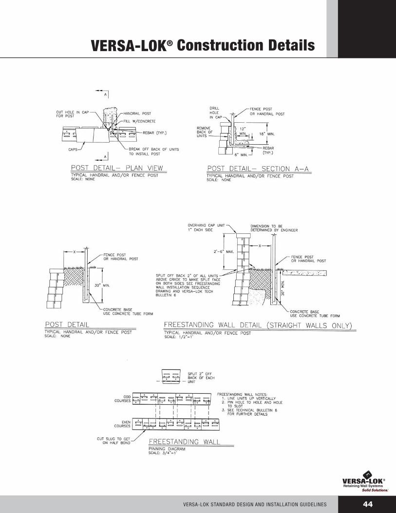
44VERSA-LOK StAndARd dESign And inStALLAtiOn guidELinES
VERSA-LOK® Construction Details
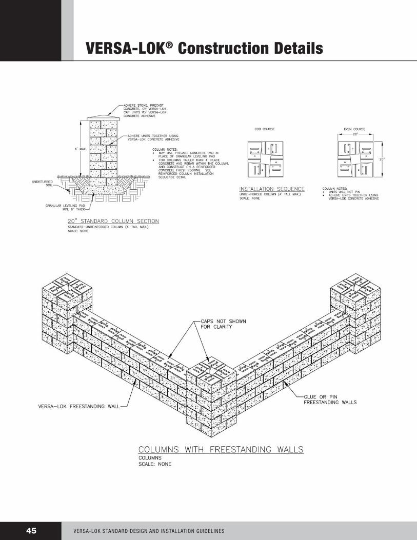
VERSA-LOK® Construction Details
VERSA-LOK StAndARd dESign And inStALLAtiOn guidELinES45

46VERSA-LOK StAndARd dESign And inStALLAtiOn guidELinES
VERSA-LOK® Construction Details

Standard Design & Installation Guidelines
Made worldwide under license from VERSA-LOK Retaining Wall Systems.Products shown may be covered by one or more of the following:
U.S. Patent D319,885, U.S. Patent D321,060, U.S. Patent D341,215, U.S. Patent D346,667, U.S. Patent D378,702, U.S. Patent D391,376, U.S. Patent D430,680, U.S. Patent D435,302, U.S. Patent D439,678, U.S. Patent D452,332, U.S. Patent D458,387, U.S. Patent 6,488,448, U.S. Patent 6,960,048, U.S. Patent 7,229,235, U.S. Patent 7,244,079, U.S. Patent D552,258, U.S. Patent
D555,810 and other U.S. patents pending; Canadian Industrial Design Registration No. 63929, No. 71472, No. 73910, No. 73911, No. 73912, No. 77816, No. 79058, No. 82288, and No. 89084. I.C.B.O. No. 4625, Canadian Patent 2,313,061
the information, including technical and engineering data, figures, tables, designs, drawings, details, suggested procedures and suggested specifications, presented in this publication is for general information only. while every
effort has been made to ensure its accuracy, this information should not be used or relied upon for any application without verification of accuracy, suitability, and applicability for the use contemplated, which is the sole responsibility of the user. a final, project-specific design should be prepared by a qualified, licensed, professional engineer based on actual site conditions.
versa-lok retaining wall systems disclaims any and all express or implied warranties of merchantability fitness for any gen-eral or particular purpose, trademark or copyright in regard to information or products contained or referred to herein.
©2010 Kiltie Corporation Printed in the U.S.A. VLS-602 4-10
6348 Hwy. 36 Blvd., Suite 1, Oakdale, MN 55128(800) 770-4525 (651) 770-3166 office (651) 770-4089 fax www.versa-lok.com