Standard AC Motors - Oriental Motor U.S.A. Corp ... AC Motors Induction Motors Synchronous Motors...
16
Standard AC Motors Induction Motors Synchronous Motors Torque Motors Watertight Motors Magnetic Brake Clutch & Brake Reversible Motors Introduction Accessories Technical Reference················································F-1 General Information ················································G-1 Additional Information A-203 Standard AC Motors Induction Motors Synchronous Motors Torque Motors Watertight Motors Magnetic Brake Clutch & Brake Brake Pack Reversible Motors Right-Angle Gearheads Accessories Introduction Before Using a Standard AC Motor Motor/Gearhead Mounting Brackets························A-204 Torque Arm······························································A-207 Flexible Couplings ···················································A-208 Motor Speed Indicator ·············································A-214 External Speed Potentiometer·································A-216 Power Relay Box for Watertight Type ······················A-216 Extension Cables ····················································A-217 DIN Rail Mounting Plate ··········································A-217 CR Circuit for Surge Suppression····························A-218 Regeneration Unit····················································A-218
Transcript of Standard AC Motors - Oriental Motor U.S.A. Corp ... AC Motors Induction Motors Synchronous Motors...

Stan
dard
AC
Mo
tors
Ind
uctio
nM
oto
rsSynchronous
Motors
Torq
ue
Mo
tors
Watertight M
otorsM
agn
eticB
rakeC
lutch
&B
rakeB
rakeP
ackR
eversibleM
otorsRight-Angle G
earheadsAccessories
Introduction
Before Usinga StandardAC M
otor
Accessories
Technical Reference················································F-1General Information················································G-1
Additional Information
A-203
Stan
dard
AC
Mo
tors
Ind
uctio
nM
oto
rsSynchronous
Motors
Torq
ue
Mo
tors
Watertight M
otorsM
agn
eticB
rakeC
lutch
&B
rakeB
rakeP
ackR
eversibleM
otorsRight-Angle G
earheadsAccessories
Introduction
Before Usinga StandardAC M
otor
Motor/Gearhead Mounting Brackets························A-204Torque Arm······························································A-207Flexible Couplings ···················································A-208Motor Speed Indicator ·············································A-214External Speed Potentiometer·································A-216Power Relay Box for Watertight Type ······················A-216Extension Cables ····················································A-217DIN Rail Mounting Plate ··········································A-217CR Circuit for Surge Suppression····························A-218Regeneration Unit····················································A-218

A-204
Stan
dard
AC
Mo
tors
For Motor Frame Size: 1.65 in. (42 mm) Model: SOL0U04Weight: 2.8 oz. (80 g) Material: Aluminumd A320U
Compatible Motor and Gearhead0GNKAMotor Frame Size 1.65 in. (42 mm) Round Shaft Type MotorsAXH Series Round Shaft Type
Dimensions Scale 1/4, Unit = inch (mm)
Model: SOL0BWeight: 3.0 oz. (85 g) Material: Aluminumd B267
Compatible Motor and GearheadAXH Series Geared Type
Dimensions Scale 1/4, Unit = inch (mm)
For Motor Frame Size: 2.36 in. (60 mm) Model: SOL2U08, SOL2M4Weight: 4.2 oz. (120 g) Material: Aluminumd A321U (SOL2U08)d A321 (SOL2M4)
Compatible Motor and Gearhead SOL2U082GNKAMotor Frame Size 2.36 in. (60 mm) Round Shaft Type Motors
SOL2M4V SeriesBX SeriesFBL2 SeriesAXU Series Round Shaft TypeAXH Series
0.79(20)
2.83 (72)
0.55
(14)
0.79
(20)
1.
42 (
36)
0.04
(1)
0.3
5 (9
)
0.83 (21)
0.29 (7.4)
0.17
(4.4
)
2.44
(62)
3.46 (88)(480.3)1.8900.012
1.73 (44)2.20 (56)
0.24 (6)
No.440 UNC4 Places
0.04
(1)
1.61
(41)
1.57
0.
02
(40
0.5)
0.12 (3)
0.31
(8)
0.79 (20)
1.57 (40)
(37
.6 0
)
0.
2
0.00
8 0
1.
480
0.79
(20)
0.55
(14)
0.17
(4.4
)0.
04 (1
)0.
35 (9
)
0.04
(1)
0.31
(8)
1.57
0.
02 (4
00.
5 )1.
61 (4
1)2.
44 (6
2)
1.
42 (
36)
(43.80.3)
0.83 (21)2.83 (72)
0.79 (20)
0.29 (7.4)
2.20 (56)1.73 (44)
1.7240.012
3.46 (88)
0.177 (4.5) 4 Holes
1.57 (40)
0.24 (6) 0.79 (20)
0.21
(5.4
)
0.98
(25)
0.33 (8.4)
1.18 (30)
3.66 (93)
0.59
(15)
0.12 (3)
1.22 (31)
0.04
(1)
0.35
(9)
3.23
(82)
2.13
(54)
4.25 (108)
2.44 (62)0.24 (6)
1.97 (50)
3.07 (78)0.87 (22)
0.04
(1)
0.31
(8)
1.97
0.
02(5
00.
5)
2.7560.012
(700.3)
1.
97 (
50)
2.
126
0.00
8
(54
0.
2 )0 0
SOL2U08: No.832 UNC4 PlacesSOL2M4: M4 P0.74 Places
Dimensions Scale 1/4, Unit = inch (mm)
Motor/GearheadMounting Brackets
Eleven kinds of mounting brackets for motors and gearheads are available. Thesebrackets come with tapped holes. To mount the motor and gearhead, simply fastenwith the screws provided to the gearhead. To mount the motor alone, mountingscrews must be provided separately. Please note that these mounting bracketscannot be used with the following products.
Right-angle Gearheads 5GCKA and 5GCHKA Watertight Motors
A-205
Stan
dard
AC
Mo
tors
Ind
uctio
nM
oto
rsSynchronous
Motors
Torq
ue
Mo
tors
Watertight M
otorsM
agn
eticB
rakeC
lutch
&B
rakeB
rakeP
ackR
eversibleM
otorsRight-Angle G
earheadsAccessories
Introduction
Before Usinga StandardAC M
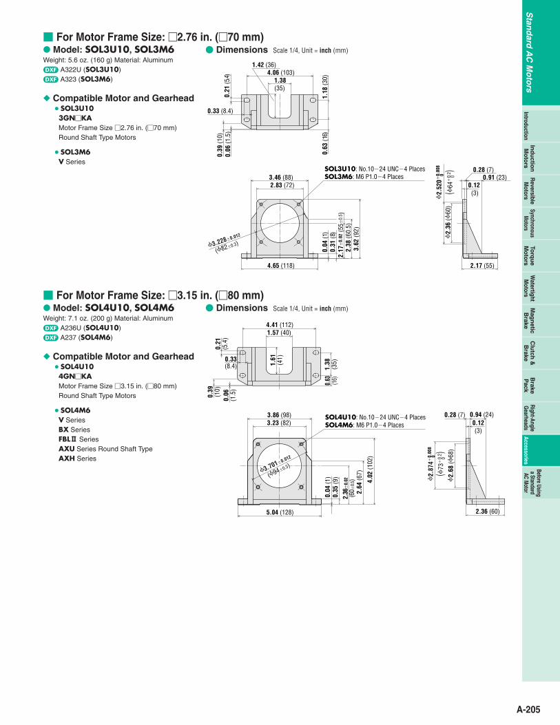
otor For Motor Frame Size: 2.76 in. (70 mm) Model: SOL3U10, SOL3M6Weight: 5.6 oz. (160 g) Material: Aluminumd A322U (SOL3U10)d A323 (SOL3M6)
Compatible Motor and Gearhead SOL3U103GNKAMotor Frame Size 2.76 in. (70 mm) Round Shaft Type Motors
SOL3M6V Series
For Motor Frame Size: 3.15 in. (80 mm) Model: SOL4U10, SOL4M6Weight: 7.1 oz. (200 g) Material: Aluminumd A236U (SOL4U10)d A237 (SOL4M6)
Compatible Motor and Gearhead SOL4U104GNKAMotor Frame Size 3.15 in. (80 mm) Round Shaft Type Motors
SOL4M6V SeriesBX SeriesFBL2 SeriesAXU Series Round Shaft TypeAXH Series
0.33 (8.4)
0.21
(5.4)
3.46 (88) 0.91 (23)
2.
36 (
60)
1.38 (35)
4.06 (103)
0.63
(16)
1.18
(30)
1.42 (36)
0.06
(1.5
)0.
39 (1
0)
4.65 (118) 2.17 (55)
0.28 (7)
2.83 (72)
0.31
(8)
2.38
(60.
5)3.
62 (9
2)
0.12 (3)
0.04
(1)
2.17
0.
02 (5
50.
5 )
3.2280.012
(820.3)
2.
520
0.00
8
(64
0.
2 )0 0
SOL3U10: No.1024 UNC4 PlacesSOL3M6: M6 P1.04 Places
4.41 (112)1.57 (40)
1.61
(41)
0.21
(5.4
)
0.39
(10)
0.33(8.4)
0.06
(1.5
)
1.38
(35)
0.63 (16)
3.86 (98)3.23 (82)
5.04 (128)
0.04
(1)
0.35
(9)
2.64
(67)
4.02
(102
)
2.36
0.
02(6
00.
5)
0.94 (24)0.28 (7)
2.36 (60)
0.12(3)
2.
68 (
68)
3.7010.012
(940.3)
2.
874
0.00
8
(73
0.
2 )0 0
SOL4U10: No.1024 UNC4 PlacesSOL4M6: M6 P1.04 Places
Dimensions Scale 1/4, Unit = inch (mm)
Dimensions Scale 1/4, Unit = inch (mm)
A-206
Stan
dard
AC
Mo
tors
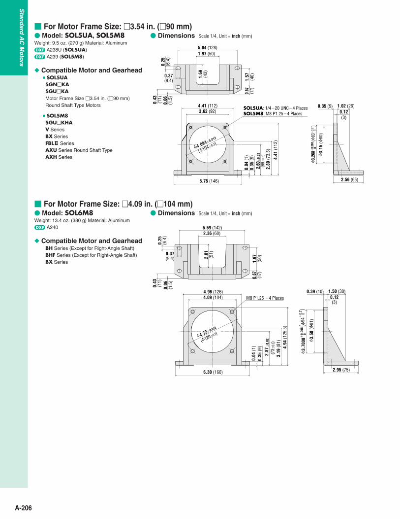
For Motor Frame Size: 3.54 in. (90 mm) Model: SOL5UA, SOL5M8Weight: 9.5 oz. (270 g) Material: Aluminumd A238U (SOL5UA)d A239 (SOL5M8)
Compatible Motor and Gearhead SOL5UA5GNKA5GUKAMotor Frame Size 3.54 in. (90 mm) Round Shaft Type Motors
SOL5M85GUKHAV SeriesBX SeriesFBL2 SeriesAXU Series Round Shaft TypeAXH Series
For Motor Frame Size: 4.09 in. (104 mm) Model: SOL6M8Weight: 13.4 oz. (380 g) Material: Aluminumd A240
Compatible Motor and GearheadBH Series (Except for Right-Angle Shaft)BHF Series (Except for Right-Angle Shaft)BX Series
5.04 (128)1.97 (50)
1.69
(43)
0.25
(6.4
)
0.43
(11)
0.37(9.4)
0.06
(1.5
)
1.57
(40)
0.67 (17)
4.41 (112)3.62 (92)
5.75 (146)
0.04
(1)
0.35
(9)
2.89
(73.
5)
4.41
(112
)
2.60
0.
02(6
60.
5)
1.02 (26)0.35 (9)
2.56 (65)
0.12(3)
4.0940.012
(1040.3)
3.
268
0.00
8 (
83
0.2
)
3.15
(80
)0
0
SOL5UA: 1/420 UNC4 PlacesSOL5M8: M8 P1.254 Places
M8 P1.25 4 Places
5.59 (142)2.36 (60)
2.01
(51)
0.25
(6.4
)
0.43
(11)
0.37(9.4)
0.06
(1.5
)
1.97
(50)
0.67
(17)
4.96 (126)4.09 (104)
6.30 (160)
4.720.012
(1200.3)
0.04
(1)
0.35
(9)
3.19
(81)
4.94
(125
.5)
1.50 (38)0.39 (10)
2.95 (75)
0.12(3)
3.
58 (
91)
(73
0.5)
0.
022.
87
(94
0
)
0.
2
0.00
8 0
3.
7008
Dimensions Scale 1/4, Unit = inch (mm)
Dimensions Scale 1/4, Unit = inch (mm)

A-207
Stan
dard
AC
Mo
tors
Ind
uctio
nM
oto
rsSynchronous
Motors
Torq
ue
Mo
tors
Watertight M
otorsM
agn
eticB
rakeC
lutch
&B
rakeB
rakeP
ackR
eversibleM
otorsRight-Angle G
earheadsAccessories
Introduction
Before Usinga StandardAC M
otor
Torque Arm
The torque arm serves as an anti-rotation guide for thegearhead when a right-angle hollow-shaft type gearhead isused in a shaft-mounted fashion (with the gearhead mountedon the shaft of a connected device). When using it as ashaft-mounted gearhead, be sure to use a torque arm andsecure the gearhead to the device.
Dimensions Scale 1/4, Unit = inch (mm)Weight: 5.1 oz. (145 g)
0.335 (8.5) 4 Holes
0.413(10.5)
2.36
2
0.00
8
(60
0.2)
3.34
10.
008
(84.
85
0.2)
3.93
70.
008
(100
0.
2)
1.98
40.
008
(50.
40.
2)4.
69(1
19.2
)
1.8740.008
(47.60.2)
2.70 (68.5)
0.38(9.6)
0.16 (4)
Panel Cutout Scale 1/4, Unit = inch (mm)For BH Series, BHF Series Right-Angle Gearhead/Hollow Shaft
0.335 (8.5) 4 Holes
0.413 (10.5)
0.31 (8)
3.54
(90)
0.31
(8)
3.54 (90)
Mounting MethodWhen mounting on a device, secure the torque arm firmlyusing an M10 or 3/8-16 UNC screw.
Motor
Washer
Spring Washer
Nut
Gearhead
Mounting Screw
Mounting Plate
Screws must be purchased separately.
M10 or 3/8-16 UNC Screw
Torque Arm
Shaft of Connected Device
Model: SOT6 Applicable Products
BH Series Right-Angle Gearhead/Hollow ShaftBHF Series Right-Angle Gearhead/Hollow Shaft5GURH Gearhead

A-208
Stan
dard
AC
Mo
tors
Flexible Couplings
Features Couplings come with shaft holes and have standardized
combinations for different diameter shaft holes. Characteristics are the same for clockwise and
counterclockwise rotation. Oil-resistant and electrically insulated. Aluminum alloy construction. The shaft being driven is not damaged, since shafts are
joined by clamping. Easy installation due to a separated hub and sleeve
design.
Mounting on a shaftThe MCL Couplings are a clamp type for mounting theflexible coupling to the shaft.
Clamp TypeClamp type couplings use the binding force of the screw tocompress the axis hole diameter and thereby fasten thecoupling to the shaft. This does not damage the shaft and iseasy to mount and remove. The following table shows thescrew tightening torque.
Alignment AdjustmentFlexible couplings tolerate misalignment of the axis centerand transfer rotational angle and torque, but producevibration when the permissible value for misalignment isexceeded. This can dramatically shorten the coupling'sservice life. Misalignment of the axis center includeseccentricity (parallel error of both centers), declination(angular error of both centers) and end play (shaft movementin the axial direction). To keep misalignment to within thepermissible value, always check and adjust the alignment. Toincrease the service life of the coupling, we recommendkeeping misalignment to below 1/3 of the permissible value.
Notes: Misalignment or excessive torque beyond the permissible values will deform the
coupling and shorten its service life. If you hear a strange metallic noise from the coupling while it is running, stop
the motor immediately and check for misalignment, shaft interference, loosescrews, or the like.
When load fluctuates substantially, paint adhesive over the screws or switch to alarger coupling diameter. This helps prevent coupling screws from comingloose.
When using couplings that have no key grooves, as on the MCL20, MCL30,MCL40 and MCL55 fasten clamping screws before fastening set screws.
Only use the screws specified by Oriental Motor. Other screws may damage thecouplings.
Do not bring fingers or hands into contact with an operating coupling as injurymay result. Always use protective covers to prevent accidents. Also, installsafety systems that stop motor rotation as soon as the protective cover isopened.
Always be sure the power is off during installation. Should the drive unitaccidentally start running, injury can occur by being drawn into the device.Always check that the devices main power supply is off before performinginstallation work.
Straight Edge Eccentricity End PlayDeclination
For Applicable Products A-209
Product Number Code
Selecting a Flexible CouplingOnce you have decided on a motor and the shaft diameter ofthe equipment to be connected to it, select the proper flexiblecoupling to use. Oriental Motor's flexible couplings areavailable in external diameter sizes that provide the strengthrequired for the motor torque.
For uniform load, when the motor is a 4GNKA (shaftouter diameter of 0.375 inch) and the shaft diameter of theequipment to be connected to the motor is 0.375 inch, usean MCL30F06F06.
For shock-applied use, when the gearhead is a 4GNKA(shaft outer diameter: 0.375 inch) and the shaft diameterof the equipment to be connected to the motor is 0.375inch, use an MCL40F06F06
MCL 30 F06 F06Example
Inner Diameter d1 Inner Diameter d2
MCL 40 F08 F10
Flexible Coupling
Outer Diameter of Coupling20: 0.79 (20 mm)65: 2.56 (65 mm)
Inner Diameter d1 (Small Inner Diameter)06: 0.2362 in. (6 mm)25: 0.9843 in. (25 mm)F03: 3/16 in. (4.762 mm)F12: 3/4 in. (19.05 mm)
Inner Diameter d2 (Large Inner Diameter)06: 0.2362 in. (6 mm)25: 0.9843 in. (25 mm)F03: 3/16 in. (4.762 mm)F12: 3/4 in. (19.05 mm)
Type
Tightening Torque
lb-in(N•m)
8.8(1)
22(2.5)
106(12)
220(25)
440(50)
Tightening Torque ofkey press screw
The screws for holding shaft flat are used for non key groove type.Fasten the screws so that they make a right angle with the surface of shaft flat.
lb-in(N•m)
6.1(0.7)
15(1.7)
15(1.7)
15(1.7)
35(4)
MCL20 MCL30 MCL40 MCL55 MCL65
A-209
Stan
dard
AC
Mo
tors
Ind
uctio
nM
oto
rsSynchronous
Motors
Torq
ue
Mo
tors
Watertight M
otorsM
agn
eticB
rakeC
lutch
&B
rakeB
rakeP
ackR
eversibleM
otorsRight-Angle G
earheadsAccessories
Introduction
Before Usinga StandardAC M
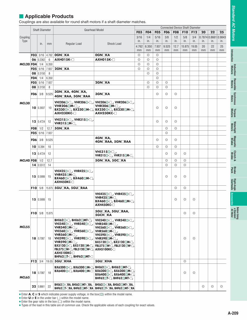
otor Applicable ProductsCouplings are also available for round shaft motors if a shaft diameter matches.
CouplingType
MCL20
MCL30
MCL40
MCL55
MCL65
Enter A, C or S which indicates power supply voltage, in the box( ) within the model name. Enter U or E in the under bar (_) within the model name. Enter the gear ratio in the box () within the model name. Types of the load in this table are of common use. Check the applicable values of each coupling for exact values.
F03 3/16 4.762 0GNKA 0GNKA
Shaft Diameter Gearhead ModelConnected Device Shaft Diameter
Regular Load Shock Loadin. mm25
mm
0.9843in.
25
22mm
0.8661in.
22
20mm
0.7874in.
20
19.05mm
3/4in.
F12
15.875mm
5/8in.
F10
12.7mm
1/2in.
F08
9.525mm
3/8in.
F06
7.937mm
5/16in.
F05
6.350mm
1/4in.
F04
4.762mm
06 0.2362 6 AXH015K- AXH015K-
F04 1/4 6.350
F05 5/16 7.937 2GNKA
08 0.3150 8
F04 1/4 6.350
F05 5/16 7.937 2GNKA
08 0.3150 8
F06 3/8 9.5253GNKA, 4GNKA, 4GNRAA, 5GNRAA
3GNKA
10 0.3937 10
VHI206 -_, VHR206 -_,VHR206 M-_, BX230 -, BX230 M-,AXH230KC-
VHI206 -_, VHR206 -_,VHR206 M-_, BX230 -, BX230 M-,AXH230KC-
12 0.4724 12VHI315 -_, VHR315 -_,VHR315 M-_
F08 1/2 12.7 5GNKA
F05 5/16 7.937
F06 3/8 9.5254GNKA, 4GNRAA, 5GNRAA
10 0.394 10
12 0.4724 12VHI315 -_, VHR315 -_, VHR315 M-_
14 0.5512 14
F08 1/2 12.7 5GNKA, 5GCKA
15 0.5906 15
VHI425 -_, VHR425 -_,VHR425 M-_BX460 -, BX460 M-,AXH450KC-
F10 5/8 15.875 5GUKA, 5GURAA
15 0.5906 15
VHI425 -_, VHR425 -_,VHR425 M-_BX460 -, BX460 M-,AXH450KC-
F10 5/8 15.8755GUKA, 5GURAA,5GCHKA
18 0.7087 18
BHI62 -, BHI62 MT-, VHI540 -_, VHR540 -_,VHR540 M-_,VHI560 -_, VHR560 -_,VHR560 M-_,VHI590 -_, VHR590 -_,VHR590 M-_, BX5120 -, BX5120 M-,FBL575 W-, FBL5120 W-,AXH5100KC-BHF62 T-, BHF62 MT-
VHI540 -_, VHR540 -_,VHR540 M-_,VHI560 -_, VHR560 -_,VHR560 M-_,VHI590 -_, VHR590 -_,VHR590 M-_,BX5120 -, BX5120 M-,FBL575 W-, FBL5120 W-,AXH5100KC-
F12 3/4 19.05 5GUKHA 5GUKHA
18 0.7087 18
BX6200 -, BX6200 M-,BX6400 -, BX6400 M-
BHI62 -, BHI62 MT-, BX6200 -, BX6200 M-,BX6400 -, BX6400 M-,BHF62 T-, BHF62 MT-,
22 0.8661 22BHI62 -RA, BHI62 MT-RA, BHF62 T-RA, BHF62 MT-RA
BHI62 -RA, BHI62 MT-RA, BHF62 T-RA, BHF62 MT-RA
3/16in.
F03
A-210
Stan
dard
AC
Mo
tors
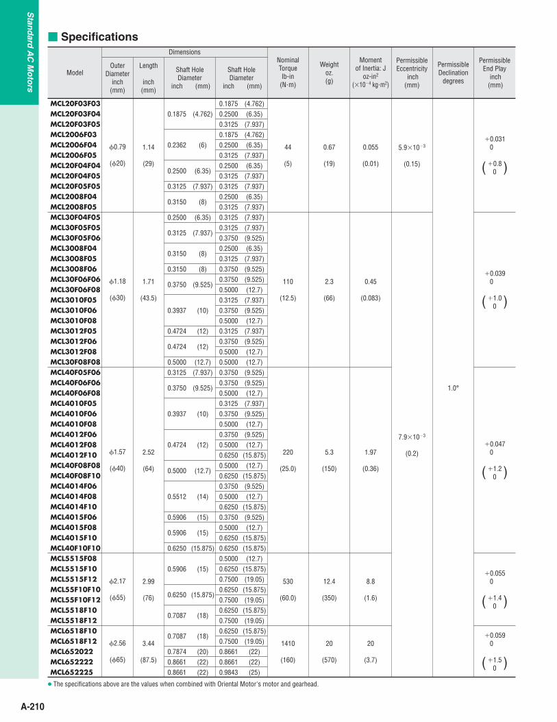
Specifications
Model
Dimensions
OuterDiameter
inch(mm)
0.79
(20)
Length
inch(mm)
Shaft HoleDiameter
inch (mm)
1.14
(29)
1.18
(30)
1.57
(40)
1.71
(43.5)
2.52
(64)
2.17
(55)
2.99
(76)
2.56
(65)
3.44
(87.5)
0.1875 (4.762)
0.2362 (6)
0.2500 (6.35)
Shaft HoleDiameter
inch (mm)
0.1875
NominalTorquelb-in
(N•m)
44
(5)
110
(12.5)
220
(25.0)
5.3
(150)
1.97
(0.36)
530
(60.0)
12.4
(350)
8.8
(1.6)
1410
(160)
20
(570)
20
(3.7)
2.3
(66)
Weightoz. (g)
0.67
(19)
Momentof Inertia: J
oz-in2
(104 kg•m2)
0.055
(0.01)
0.45
(0.083)
7.9103
(0.2)
PermissibleEccentricity
inch(mm)
5.9103
(0.15)
PermissibleDeclination
degrees
1.0°
PermissibleEnd Play
inch(mm)
0.0310
0.80( )
0.0390
1.00( )
0.0470
1.20
0.0550
1.40
( )
( )
0.0590
1.50( )
(4.762)0.2500 (6.35)0.31250.18750.25000.3125
(7.937)(4.762)(6.35)(7.937)
0.2500 (6.35)
0.3125 (7.937) 0.3125 (7.937)
0.3150 (8)
0.3125 (7.937)
0.3150 (8)
0.2500 (6.35)
0.2500 (6.35)0.3125 (7.937)0.3125 (7.937)0.3125 (7.937)0.3750 (9.525)0.2500
0.3150 (8) 0.3750
(6.35)
(9.525)
0.3750 (9.525)0.3750 (9.525)
0.3937 (10)
(12)
0.3125 (7.937)
0.4724 0.3125 (7.937)
(12)0.47240.3750 (9.525)
(12.7)0.5000 0.5000 (12.7)(7.937)0.3125
(9.525)0.3750
0.3750 (9.525)0.3750 (9.525)
(10)0.39370.3125 (7.937)0.3750 (9.525)0.5000 (12.7)
(12)0.47240.3750 (9.525)0.5000 (12.7)
(12.7)0.50000.5000 (12.7)0.6250 (15.875)
(14)0.55120.3750 (9.525)
(15)0.5906 0.3750 (9.525)
(15.875)
(15)0.59060.5000
(15.875)0.6250 0.6250(12.7)
(15)0.59060.5000
(15.875)(15.875)0.6250
0.6250
(15.875)0.6250(19.05)0.7500
(19.05)0.7500(15.875)
(18)0.70870.6250
(19.05)0.7500(15.875)
(18)0.70870.6250
(22)(20)0.7874 0.8661(22)(22)0.8661 0.8661(25)(22)0.8661 0.9843
(19.05)0.7500
(12.7)0.6250 (15.875)
0.5000 (12.7)0.6250 (15.875)
0.6250 (15.875)
0.5000 (12.7)
0.5000 (12.7)
0.3750 (9.525)0.5000 (12.7)
0.5000 (12.7)
0.3125 (7.937)
0.3125 (7.937)
MCL20F03F03MCL20F03F04MCL20F03F05MCL2006F03MCL2006F04MCL2006F05MCL20F04F04MCL20F04F05MCL20F05F05MCL2008F04MCL2008F05MCL30F04F05MCL30F05F05MCL30F05F06MCL3008F04MCL3008F05MCL3008F06MCL30F06F06MCL30F06F08MCL3010F05MCL3010F06MCL3010F08MCL3012F05MCL3012F06MCL3012F08MCL30F08F08MCL40F05F06MCL40F06F06MCL40F06F08MCL4010F05MCL4010F06MCL4010F08MCL4012F06MCL4012F08MCL4012F10MCL40F08F08MCL40F08F10MCL4014F06MCL4014F08MCL4014F10MCL4015F06MCL4015F08MCL4015F10MCL40F10F10MCL5515F08MCL5515F10MCL5515F12MCL55F10F10MCL55F10F12MCL5518F10MCL5518F12MCL6518F10MCL6518F12MCL652022MCL652222MCL652225
The specifications above are the values when combined with Oriental Motor's motor and gearhead.

A-211
Stan
dard
AC
Mo
tors
Ind
uctio
nM
oto
rsSynchronous
Motors
Torq
ue
Mo
tors
Watertight M
otorsM
agn
eticB
rakeC
lutch
&B
rakeB
rakeP
ackR
eversibleM
otorsRight-Angle G
earheadsAccessories
Introduction
Before Usinga StandardAC M
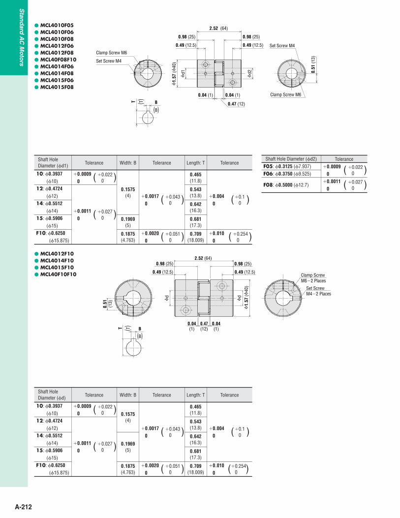
otor Dimensions Scale 1/4, Unit = inch (mm) MCL20 Type
MCL30 Type
MCL3010F05 MCL3010F06 MCL3010F08 MCL3012F05 MCL3012F06 MCL3012F08
MCL40F05F06 MCL40F06F06 MCL40F06F08 MCL40F08F08
0.49 (12.5) 0.49 (12.5)
0.98 (25) 0.98 (25)
2.52 (64)
0.04 (1)
0.47 (12)
0.04 (1)
1.
57 (
40) Set Screw M4
Clamp Screw M6
Set Screw M4
Clamp Screw M6
0.51
(13)
d1
d2
Clamp ScrewM42 Places
0.39(10)
1.71 (43.5)
0.31(8)
0.63 (16) 0.63 (16)0.31(8)
0.03(0.75)
0.03(0.75)
0.39(10)
1.
18 (
30)
Set ScrewM42 Places
d2
d1
(T
0 )
0.
1
0.
0039
0T
(B 0 )0.043
0.0017 0B
Clamp ScrewM42 Places
Set Screw M42 Places
0.39(10)
1.71 (43.5)
0.31(8)
0.31(8)
0.63 (16) 0.63 (16)
0.03(0.75)
0.03(0.75)
0.39(10)
1.
18 (
30)
d2
d1
Clamp ScrewM2.52 Places
Set ScrewM32 Places
0.26(6.5)
0.39(10)
1.14 (29)
0.20 (5)
0.39(10)
0.20 (5)
0.02(0.5)
0.02(0.5)
0.31(8)
0.
79(
20)
d1
d2
Shaft Hole Diameter (d1, d2)F03: 0.1875 (4.762)06: 0.2362 (6)
Tolerance0.0007
00.018
0( )F04: 0.2500 (6.35)F05: 0.3125 (7.937)08: 0.3150 (8)
0.00090
0.0220( )
Shaft Hole Diameter (d1, d2)F04: 0.2500 (6.35)F05: 0.3125 (7.937)08: 0.3150 (8)
F06: 0.3750 (9.525)
Tolerance
0.00090
0.0220( )
F08: 0.5000 (12.7)0.0011
00.027
0( )
Shaft Hole Diameter (d1)
10: 0.3937 (10)
Tolerance Width:B0.0009
00.022
0( )0.1575
(4)
Length:T
0.465(11.8)
0.543(13.8)
12: 0.4724 (12)0.0011
00.027
0( )
Shaft Hole Diameter (d2)F05: 0.3125 (7.937)F06: 0.3750 (9.525)
Tolerance0.0009
00.022
0( )F08: 0.5000 (12.7)
0.00110
0.0270( )
Shaft Hole Diameter (d1, d2)F05: 0.3125 (7.937)F06: 0.3750 (9.525)
Tolerance0.0009
00.022
0( )F08: 0.5000 (12.7)
0.00110
0.0270( )
A-212
Stan
dard
AC
Mo
tors
MCL4010F05 MCL4010F06 MCL4010F08 MCL4012F06 MCL4012F08 MCL40F08F10 MCL4014F06 MCL4014F08 MCL4015F06 MCL4015F08
Set Screw M4
Set Screw M4
Clamp Screw M6
0.49 (12.5)0.49 (12.5)
0.98 (25)0.98 (25)
2.52 (64)
0.04 (1)
0.47 (12)
0.04 (1)
0.51
(13)
Clamp Screw M6
(B)B(T)T
1.
57 (
40)
d2
d1
Shaft Hole Diameter (d1)
10: 0.3937(10)
Tolerance Width: B
0.1575(4)
0.1969(5)
0.1875(4.763)
Length: T
0.465(11.8)
0.543(13.8)
0.642(16.3)
0.681(17.3)
0.709(18.009)
0.00090
0.0220( )
12: 0.4724(12)
14: 0.5512(14)
15: 0.5906(15)
F10: 0.6250(15.875)
0.00110
0.0270( )
Tolerance
0.00170
0.0430( )
0.00200
0.0510( )
Tolerance
0.0040
0.10( )
0.0100
0.2540( )
Shaft Hole Diameter (d2)F05: 0.3125 (7.937)F06: 0.3750 (9.525)
F08: 0.5000 (12.7)
Tolerance0.0009
00.022
0( )0.0011
00.027
0( )
MCL4012F10 MCL4014F10 MCL4015F10 MCL40F10F10
0.51
(13)
2.52 (64)
0.49 (12.5) 0.49 (12.5)
0.98 (25)
0.04(1)
0.04(1)
0.47(12)
0.98 (25)
Clamp ScrewM62 Places
Set ScrewM42 Places
1.
57 (
40)
d
d
(B)B(T)T
Shaft Hole Diameter (d)
10: 0.3937(10)
Tolerance Width: B
0.1575(4)
0.1969(5)
0.1875(4.763)
Length: T
0.465(11.8)
0.543(13.8)
0.642(16.3)
0.681(17.3)
0.709(18.009)
0.00090
0.0220( )
12: 0.4724(12)
14: 0.5512(14)
15: 0.5906(15)
Tolerance
0.00170
0.0430( )
0.00200
0.0510( )
Tolerance
0.0040
0.10( )
0.0100
0.2540( )
0.00110
0.0270( )
F10: 0.6250(15.875)

A-213
Stan
dard
AC
Mo
tors
Ind
uctio
nM
oto
rsSynchronous
Motors
Torq
ue
Mo
tors
Watertight M
otorsM
agn
eticB
rakeC
lutch
&B
rakeB
rakeP
ackR
eversibleM
otorsRight-Angle G
earheadsAccessories
Introduction
Before Usinga StandardAC M
otor
MCL55 Type
Set ScrewM42 Places
0.77
(19.
5)
Clamp ScrewM82 Places
2.99 (76)
0.59(15)
1.18 (30)
0.04(1)
0.55(14)
2.
17 (
55)
0.59(15)
0.04(1)
1.18 (30)
d
B(B)
T (T)
d
MCL5515F08
0.59(15)
0.59(15)
0.04(1)
0.04(1)
1.18 (30) 1.18 (30)
2.99 (76)
2.
17 (
55)
Set Screw M4 Clamp Screw M8
0.55(14)
0.77
(19.
5)
Clamp Screw M8
Set Screw M4
0.043(5 0 )0.1969
0.00170
(17.
3 0
)0.
6811
0.
004
0
0.1 ( 1
50.
027 )
0
0
0.00
11
0.59
06
(12
.7
0.02
7 )0
0
0.00
11
0.50
00
Shaft Hole Diameter (d)
15: 0.5906(15)
Tolerance Width: B
0.1969(5)
0.2362(6)
0.1875(4.763)
0.1875(4.763)
Length: T
0.681(17.3)
0.819(20.8)
0.709(18.009)
0.837(21.260)
0.00110
0.0270( )18: 0.7087
(18)F10: 0.6250
(15.875)F12: 0.7500
(19.050)
Tolerance
0.00170
0.0430( )
0.00200
0.0520( )
0.00200
0.0510( )
0.00200
0.0510( )
Tolerance
0.0040
0.10( )
0.0040
0.10( )
0.0100
0.2540( )
0.0100
0.2540( )0.0013
00.033
0( )
A-214
Stan
dard
AC
Mo
tors
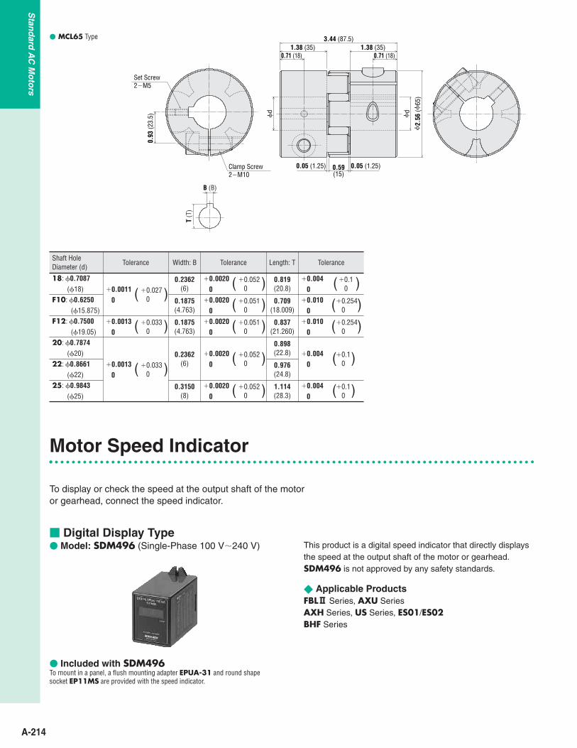
MCL65 Type
Clamp Screw2M10
Set Screw2M5
0.93
(23.
5)
3.44 (87.5)
0.71 (18)1.38 (35)
0.05 (1.25) 0.59(15)
2.
56 (
65)
1.38 (35)0.71 (18)
0.05 (1.25)
B (B)T
(T)
d
d
Shaft Hole Diameter (d)
18: 0.7087(18)
Tolerance Width: B
0.2362(6)
0.1875(4.763)
0.1875(4.763)
0.2362(6)
Length: T
0.819(20.8)
0.709(18.009)
0.837(21.260)
0.898(22.8)
0.976(24.8)
F10: 0.6250(15.875)
F12: 0.7500(19.05)
20: 0.7874(20)
22: 0.8661(22)
25: 0.9843(25)
Tolerance
0.00200
0.0520( )
0.00200
0.0510( )
0.00200
0.0510( )
0.00200
0.0520( )
Tolerance
0.0040
0.10( )
0.0100
0.2540( )
0.0100
0.2540( )
0.0040
0.10( )
0.00130
0.0330( )
0.3150(8)
1.114(28.3)
0.00200
0.0520( ) 0.004
00.1
0( )
0.00110
0.0270( )
0.00130
0.0330( )
Motor Speed Indicator
To display or check the speed at the output shaft of the motor or gearhead, connect the speed indicator.
Digital Display Type Model: SDM496 (Single-Phase 100 V240 V)
Included with SDM496To mount in a panel, a flush mounting adapter EPUA-31 and round shapesocket EP11MS are provided with the speed indicator.
This product is a digital speed indicator that directly displaysthe speed at the output shaft of the motor or gearhead.SDM496 is not approved by any safety standards.
Applicable ProductsFBL2 Series, AXU SeriesAXH Series, US Series, ES01/ES02BHF Series

A-215
Stan
dard
AC
Mo
tors
Ind
uctio
nM
oto
rsSynchronous
Motors
Torq
ue
Mo
tors
Watertight M
otorsM
agn
eticB
rakeC
lutch
&B
rakeB
rakeP
ackR
eversibleM
otorsRight-Angle G
earheadsAccessories
Introduction
Before Usinga StandardAC M
otor Dimensions Scale 1/4, Unit = inch (mm)Weight: 7.1 oz. (200 g)d A100
Dimensions with Adapter AttachedScale 1/4, Unit = inch (mm)
EP11MS
EPUA31
2.36 (60) 0.24 (6) 2.95 (74.9) 1.06 (27)
3.15
(80)
2.83
(72)
1.94 max. (49.4) 3.19 max. (80.9)0.28(7)
3.15
(80)
2.40
max
. (61
.4)
0.22
(5.5
)
0.14 (3.5)
Flush Connecting Socket for Mounting DIN Rail(Model: EP11PF) (Sold separately)Weight: 2.8 oz. (75 g)
Panel Cut-Out
2.56
0
0.
02
( 65
0
)
0.5
2.09 00.02
(53 0 )0.5
R0.02 max. (0.5)
M3.5 Screws11 Places
0.177 (4.5)2 HoleMounting Hole
3.35
max
. (85
)3.
19 m
ax. (
81)
2.01 max. (51)1.5740.008
0.33
(8.4
)
0.20(5)
0.16(4)
4.65
max
. (11
8)
0.31(7.8) 0.16
(4)
1.39
(3
6.4)
1.40 max.(35.5)
(400.2)
Example of Connection AXU Series, AXH Series (30 pulses/rotation)
For AXU Series, replace "GND" with "COM".
756
2109
SDM496
Power Supply InputSingle-Phase 100 VAC240 VAC50/60 Hz
FG
SPEED OUTGND
Driver
SPEED Input Signal
GND12 Pulses/30 Pulses Selection
US Series
SPEED OUTNo Polarity
2109
Power Supply InputSingle-Phase 100 VAC240 VAC50/60 Hz
FG
111
Tachogenerator leads Input Signal
SDM496
Tachogenerator leads Input Signal
Speed Control Pack
BHF Series
75
2109
SDM496
Power Supply InputSingle-Phase 100 VAC240 VAC50/60 Hz
FG
S-MON0-COM
Inverter
SPEED Input Signal
GND
FBL2 Series (12 pulses/rotation)
756
2109
SDM496
Power Supply InputSingle-Phase 100 VAC240 VAC50/60 Hz
FG
SPEED OUTGND
Driver
SPEED Input Signal
GND12 Pulses/30 Pulses Selection Not
connected
ES01/ES02
2109
Power Supply InputSingle-Phase 100 VAC240 VAC50/60 Hz
FG
111
1011
To Generator of Speed Control MotorBlue
SDM496
Tachogenerator leads Input Signal
Tachogenerator leads Input Signal Blue
ES01/ES02

A-216
Stan
dard
AC
Mo
tors Model: PAVR-20KZ
(20 kΩ, 1/4 W, with a linear resistance vs. angle curve)
Applicable ProductsBX SeriesFBL2 SeriesAXH SeriesBHF SeriesES01/ES02
Dimensions Scale 1/2, Unit = inch (mm)Weight: 0.71 oz. (20 g)
A dial plate provided with the speed potentiometer. Recommended thickness of a mounting plate is a maximum 0.177 inch (4.5
mm).
Note: One set of this external speed potentiometer is provided with speed control
packs and drivers shown for the applicable products on the left (Except forAXH Series and BHF Series).
0.37 (9.5) 0.59 (15)
0.12 ( 3
)
(Screw)
KnobDial plate1.57 (40)t=0.02 (0.5)
Insulated sheet1.57 (40)t=0.02 (0.5)
Potentiometer
1.57 (40)
0.30 (7.5)
0.49
( 12.5
)
1.57
( 40)
Insulated sheet
0.12 0.008
(3 0.2)0.370.008
(9.50.2)
1.18 min. (30)
0.
79(
20)
0.
79(
20)
M4 P0.7
0.
11 (
2.8)
0.24 (6)
External Speed Potentiometer
Model: TB4-0608 (4-Terminal Type)
Applicable MotorsFPW SeriesBH SeriesApplicable cable diameter:
0.26 in. (6.5 mm)0.33 in. (8.5 mm)
Power Relay Box for Watertight Type
Dimensions Scale 1/4, Unit = inch (mm)Weight: 5.3 oz. (150 g)
The relay box conforms to the protection level IP65 onlywhen used with a splash proof extension cable for an FPWseries motor. (Does not conform to the protection levelIP65 when used with a BH Series motor.)
The screws for the cover on the sealed connector and relay box should beadjusted to the torque shown below.Sealed connector 8.813.2 lb-in. (1.01.5 N•m)Cover of power relay box 4.75.8 lb-in. (0.540.66 N•m) This product can be used with lead wire type motors. However, they are not
waterproof. Also, note that lead wires cannot be fixed with the sealedconnectors.
1 2 3 4
Inside of The Terminal Box
M3.5 0.31 (8)
2.83 (72)
1.97
(50)
2.76 (70)
1.65
(42)
0.17
(4.3
)
3.19 (81)
0.06 (1.5) 0.28 (7)0.33(8.5)
0.63 (16)
1.59
(40.
5)0.
28 (7
)
5.35 max. (136)

A-217
Stan
dard
AC
Mo
tors
Ind
uctio
nM
oto
rsSynchronous
Motors
Torq
ue
Mo
tors
Watertight M
otorsM
agn
eticB
rakeC
lutch
&B
rakeB
rakeP
ackR
eversibleM
otorsRight-Angle G
earheadsAccessories
Introduction
Before Usinga StandardAC M
otor
Use with the power relay box for watertight. An extension of 16.4 ft. (5 m) and 32.8 ft. (10 m) is possible.
Extension Cables
Conductors
3 Conductors
4 Conductors
Applicable Product
BH Series
BH SeriesFPW Series
Cable Length Lft. (m)
16.4 (5)32.8 (10)16.4 (5)32.8 (10)
Models
CC05AC33PCC10AC33PCC05AC43PCC10AC43P
SpecificationsConductor construction: Refer to the dimension on the rightFinished outer diameter: 3 conductors, 4 conductors: 0.31 in. (7.8 mm)Outer casing: Heat-resistant vinyl chloride
1.97 (50) 1.97 (50)
Conductors3 Conductors: UL Style 3271, AWG 2034 Conductors: UL Style 1015, AWG 203
UL Style 1430, AWG 201
L
DIN Rail Mounting Plate
For Drivers and Speed Control PacksThis mounting plate is convenient for installing the speed control packs and drivers on DIN rails with ease.
Model: PADP01
Applicable MotorsBX SeriesFBL2 SeriesBHF Series
Dimensions Scale 1/4, Unit = inch (mm)Weight: 0.71 oz. (20 g)
DIN Rail Center
1.34(34)
1.93
(49)
3.50
(89)
0.71(18)
0.43
(11)
4.72
(120
)
0.66(16.8)
5.73
(145
.5)
0.31(8)
0.18(4.5)
Unit = inch (mm)

A-218
Stan
dard
AC
Mo
tors
Regeneration Unit
This absorbs energy that is regenerated during avertical (gravitational) operation or an abrupt start/stop.
Model: EPRC-400P
Dimensions Scale 1/4, Unit = inch (mm)Weight: 8.8 oz. (250 g)d C194
R: 400 Ω
302°F (150°C) (NC)
0.79
( 20)
0.05
( 1.2
)
1.65
( 42)
0.17
0.
012
0
(4.2
0.
3 )0
0.170.0120
(4.20.3 )0
1.10
( 28)
7.17 (182)
UL style 3071 AWG 18 WhiteUL style 3122 AWG 22 White
6.50 (165)5.91 (150) 11.8 (300)
0.24 (6)
➀ ➁➂ ➃
➀–
➁– ➂
➃: AWG 18x2 For regeneration current Connect to RG Terminal
: AWG 22x2 For thermal signal (For BHF Series, connect to I-COM and TP terminal)
Model: EPCR1201-2250 VAC (120 Ω, 0.1 F)
Dimensions Scale 1/2, Unit = inch (mm)Weight: 0.18 oz. (5 g)
0.59min.(15)
0.690.02
(17.50.5)
0.
03
0.02
(0.
80.
05)
0.79
(20)
0.330.02
(8.50.5)
0.93
0.
02
(23.
50.
5)
This product is used to protect the contacts of the relayand/or switch used in the forward/reverse circuitsection or the instantaneous stop circuit section of amotor.
CR Circuit for Surge Suppression
Specifications
Applicable MotorsBHF Series
Item SpecificationsRated Electric Power 100 WResistance 400 ΩInsulation Resistance 100 MΩ or more when 500 VDC is applied
Dielectric StrengthSufficient to withstand 1.5k VAC at 50 Hz applied
Ambient Temperature14 °F122 °F (10°C50°C)(nonfreezing)
Ambient Humidity 85% maximum (noncondensing)
Operating TemperatureThermalSignal
Rated Load
Open: 3029°F (1505°C), Close: 24818°F (12010°C)
125 VAC 100 mA, 30 VDC 100 mA


![AC/DC Geared Motor and Gearhead - RAVEO s.r.o ...katalog]_DKM...- S.C. Induction Motor - S.C. Reversible Motor - S.C. E.M. Brake Motor - S.C. Clutch & Brake Motor AC MOTORS Lead Wire](https://static.fdocuments.net/doc/165x107/5b0a4a0b7f8b9aba628bec71/acdc-geared-motor-and-gearhead-raveo-sro-katalogdkm-sc-induction.jpg)