Stair Parts Installation Tips Tricks - Alexandria...
50
Stair Parts Installation Tips Tricks &
Transcript of Stair Parts Installation Tips Tricks - Alexandria...

Stair PartsInstallationTips Tricks
&


1
Introduction
Your DIY staircase guide
Welcome to the Stairpart home
installation guide. Your stairway is both
a functional and focal point in your home,
so keeping it in good shape
and looking great is important. This user-
friendly guide is full of tips and tricks to
make the renovation or repair of any post-
to-post staircase, safe and easy.
For a full staircase replacement or for
more complex staircase configurations,
we recommend that you contact an indus-
try professional. In all cases, please check
your local building code prior
to begin your project.

2
Table of Content Introduction ...............................................................................................1
Table of Content .......................................................................................2
The 5 R’s of Stairparts ........................................................................3-4
Stairway Terminology ..............................................................................5
Requirements ............................................................................................6
Tools ............................................................................................................7
Installation ....................................................................................................
Stair Treads & Risers .....................................................8-9
Newel Posts ...............................................................10-11
Handrail .......................................................................12-13
Balusters .....................................................................14-20
Finishing ............................................................................ 20
Accessories .................................................................................................
Wall Mount Rosette ........................................................ 21
Handrail Bracket .............................................................. 21
Stair Tread Bullnose Cap .............................................. 21
Hardware ...................................................................................................
Newel Post Mounting Kit ............................................... 22
Baluster Mounting Kit .................................................... 22
Handrail & Newel Post Connector .............................. 23
Handrail – Bolt Connector ............................................ 23
Newel Post Mounting Plate .......................................... 24
Visual Glossary ................................................................................25-29

The 5 R’s of Stairparts
Replace Your Old Fashioned Staircase
It’s out with the old and in with the new with a complete staircase removal and replacement.
Repair Your Damage Staircase
Ensure staircase safety with simple part replacement or reinforcement for loose handrails, balusters, and more.
Revive Your Tired Staircase
Remove old, dated staircase parts and add beautiful oak and pine parts to your existing staircase.
Refine Your Plain Staircase
Add flair and refinement to your existing staircase with an elegant handrail, maple baluster, wall mount rosettes, and more.
Reinvent Your Boring Staircase
The only limit is your imagination when you mix and match combi-nations to your personal style.
3

4
After
Before

5
Newel Post
Square Top Baluster
Stairway TerminologyFor those who are new to the world of stairparts, use the illustration below to familiarize yourself with the language of stairs and stairparts.
Stair Riser
Handrail
Stringer
Stair Tread

RequirementsDetermine the components you require for your staircase
6
1. Treads
Equal to number of steps required
2. Risers
Equal to the number of treads plus 1
3. Newel Posts
1 Newel Post placed at each end of handrail
1 Newel Post every handrail change in direction
1 Half Newel Post or Wall Mount Rosette when handrail finishes at wall
1 Newel Post to divide a long, horizontal section
4. Handrail
Footage of handrail = Number of Treads + 1 (eg. For 13 Treads, 14 feet of handrail required)
5. Short balusters
Stairway application: 1 baluster at front of each tread
6. Long balusters
Stairway application:1 baluster at back of each tread
Hallway application: 3 balusters per foot of handrail
Number of Components
Required

ToolsHand Drill
Hammer
Putty Stick - to match color of stain
Miter Box Saw
Ratchet Wrench
Level
Tape Measure
Sandpaper
Handsaw
Carpenter Glue
Construction Adhesive
Plumb Bob
7
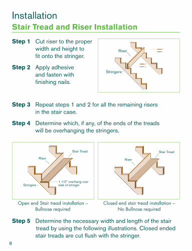
Step 1 Cut riser to the proper width and height to fit onto the stringer.
Step 2 Apply adhesive and fasten with finishing nails.
Step 3 Repeat steps 1 and 2 for all the remaining risers in the stair case.
Step 4 Determine which, if any, of the ends of the treads will be overhanging the stringers.
Step 5 Determine the necessary width and length of the stair tread by using the following illustrations. Closed ended stair treads are cut flush with the stringer.
Open end Stair tread installation – Bullnose required
Closed end stair tread installation – No Bullnose required
InstallationStair Tread and Riser Installation
Stringers
Riser
Riser
Stair Tread
Stringers1 1/2" overhang over side of stringer
Riser
Stair Tread
8

Step 6 Cut stair tread to proper dimensions.
Step 7 If installing an open end stair tread, attach a bullnose to each end of the stair tread that overhangs the stringer.
Step 8 Attach stair tread using construction adhesive and 4 2-1/2” wood screws countersunk into the surface.
Step 9 Apply adhesive to suitable size plugs, insert into the screw holes and sand smooth when dry.
Step 10 Repeat process for all further stair treads requiring installation.
Note In more advanced installations, the stair treads can be secured from underneath eliminating the need for plugs.
Riser Stair Tread
1 1/2" overhang
Cove Moulding
Riser
Riser
1 1/2" overhang
Cove Moulding
Stair Tread
Bullnose Cap
Stringers
Stair Tread
Side View Front View (Open end)
9

Step 1 Construct a baluster line. Balusters and newel posts are all centered along the same baluster line. This is calcu-lated by determining the exact location of all the balus-ters on the stair tread. The edge of each baluster should be 1.5” from the front edge of the stair tread. The center point of the balusters can be determined by calculating the width of the baluster, dividing by 2, and adding 1.5. For example the center point of a 1.5” baluster would be 2.25” from the edge of the stair tread (1.5” baluster/2 = .75” + 1.5” edge room = 2.25”). The center points of the newel posts lie along the same baluster line.
Newel Posts Installation
Stair Tread
WA
LL TOP VIEW
Stair Tread Leading Edges
Down to floor
To Upper Floor
Distance of baluster center point = 1 1/2" + (baluster width/2)
Baluster
Landing
Newel Post
Edge of Baluster
1 1/2"
Stair Tread Bullnose
Edge of wall or skirtobard
10

Step 2 Determine the length between the starting newel Post and the landing newel Posts. The height of the handrail measured from the leading edge of every tread must meet the local building code. Account for 1” above the handrail on the top square block of the newel Post.
Step 3 Cut newel Posts to appropriate size.
Step 4 Install the starting newel Post, landing newel Post, and/or half-newel Posts with Newel Post Mounting Kit A (p. 22) or Newel Post Mounting Plate E (p. 24)
Note
1 A Modern Style staircase installation does not require newel posts.
2 For hallway installations, an extra newel post is recommended to be installed for long sections.
Handrail
Newel Post
Check local Building Codes
1"
Riser
4 1/2" 4 1/2"
RiserLong baluster: placed evenly between two adjacent short balusters
Short baluster: front edge even with riser of lower step
11

Stairway Hallway
Handrail Installation
Canada building code requirements
Stairway HandrailHandrails cannot exceed 38” from front edge of each tread to top of handrail.
Hallway HandrailHandrail required on landings shall not exceed 42” in height.
2 finishing nails 2"
Hardwood
Softwood 2 screws 2 1/2"
Softwood 2 screws 2 1/2"
Hardwood
Hardwood
With shoerail
Without shoerail
12

Stairway Installation
Step 1 Lay a section of the handrail across the tread nosing and secure with a clamp.
Step 2 Mark the handrail cuts where the newel and handrail intersect.
Step 3 Make the appropriate cut ensuring the handrail is at the correct angle and length.
Step 4 Dry fit the handrail to ensure a proper fit.
Step 5 Install handrail at the appropriate height with Handrail Bolt Connector D (p. 23) on each side.
Hallway Installation
Step 1 Measure distance between newel posts and cut handrail to the proper length.
Step 2 Dry fit the handrail to ensure a proper fit.
Step 3 Install handrail at the appropriate height with a Handrail Bolt connector D (p. 23) on each side.
TipsTo make a proper angled cut
1 Cut handrail to about ¼” oversize to make sure angles are correct.
2 Make a final precision cut to finished size.
It is better to cut the handrail initially too long then too short.
Mark and cut here
13

A) Square Top Baluster InstallationStairway Installation
Step 1 Balusters are installed so the distance between each does not exceed 4” center to center. There are typically two balusters per tread. A long baluster is used for the back of each tread and a short baluster is used for the front of each tread.
Step 2 Mark the location of the centre of each baluster on the stair treads. Refer to Newel Post Installation section for details on constructing a baluster line.
Step 3 If using dowel pin to secure baluster to the tread, drill a ¾” by 1” deep hole for each baluster center.
Step 4 Cut each baluster top to proper height and angle.
Baluster Installation
Note Balusters can be attached to floor using any of 3 methods:
1 Dowel pin: A ¾” x 1” deep hole is drilled in each baluster location and baluster is inserted into hole.
2 Shoerail: The dowel pin is cut off.
3 Baluster Mounting Kit (B): The dowel pin is cut off.
The maximum space between the center of balusters cannot exceed 4”
14

Hallway Installation
Step 1 The maximum spacing between centers of balusters is 4”. In order for the balusters to be evenly spaced, the following formulas are used to determine the number of balusters required and the distance between each baluster.
D = Distance between newel posts or walls # of balusters = (D/4) rounded up Distance between balusters = D/# of balusters
Ex. If D = 50” # of balusters = (50/4) = 12.5 = 13 Distance between balusters = 50”/13 = 3.846”
15
Step 5 Install the balusters beginning at the bottom of the stairway. Insert each baluster into the dowel hole or sho-erail and the top into the plow of the handrail. Use a level to ensure they are plum. For flat bottom baluster installa-tion, use Baluster Mounting Kit (B) (p. 22).
Step 6 Pre-drill and attach baluster into the plow under the handrail with appropriate finishing nails.
Step 7 Cut the handrail fillets to fit in be-tween the tops of each baluster.
Step 8 Affix fillets using construction adhesive and finishing nails.
Note
Do not forget to add the depth of the groove on the handrail.

Step 2 Mark centre point of each baluster using the calculated “Distance between balusters”.
Step 3 If using dowel pin to secure baluster to floor, drill a ¾” by 1” deep hole for each baluster centre.
Step 4 Cut the top of each baluster to proper height. Note: Do not forget to add
the depth of the groove on the handrail.
Step 5 Insert each baluster into the dowel hole or shoerail and the top into the plow of the handrail. Use a level to ensure they are plum.
Step 6 Pre-drill and attach baluster into the plow under the handrail with appropriate finishing nails.
Step 7 Cut the handrail fillets to fit in between the tops of each baluster.
Step 8 Affix balusters and fillets using construction adhesive and finishing nails.
16
Fillet
Shoerail
Shoerail
Fillet
Balusters

Panel baluster illustrationWrought iron illustration
17
B) Wrought Iron InstallationStep 1 Balusters are installed so the distance between each
does not exceed 4”. There are typically two balusters per tread. A long baluster is used for the back of each tread and a short baluster is used for the front of each tread.
Step 2 Mark the location of the centre of each baluster on the stair treads. Refer to Newel Post Installation section for details on constructing a baluster line.
Step 3 Beginning at the bottom of the staircase, install the balusters by affixing them to the handrail and treads with the screws provided in the wrought iron package, using a level to ensure they are plum.
Note Wrought iron balusters are sold in styles for either Stairway or Hallway installations. Stairway balusters have an angled top and hallway balusters have a flat top for ease of installation.

18
C) Modern Style InstallationThe modern railing system requires 2 short and one long baluster be installed on the first tread.
Stairway Installation
Step 1 Mark the location of the centre of the first short baluster ½” from the front of the riser and ½” from the edge of the false stringer.
Step 2 Mark the location of the centre of the second short baluster 2-1/8” to the side of the first center point.
Step 3 Using the same measurements as in step 1, mark the lo-cation of the center point of the short balusters on each tread for all remaining treads.
Step 4 To determine the location of the center point of the long baluster, calculate the horizontal distance between the center points of the 2 short balusters (as determined in steps 1 & 3), and divide by 2. Mark the location of the center point of the long balusters on each tread for all remaining treads.
Step 5 If using dowel pin to secure baluster to the tread, drill a ¾” by 1” deep hole for each baluster centre.
Step 6 Mark the location of the center point of the first baluster on the landing.
Note Landing or Hallway balusters are all long, ensuring it is ½” from the front of the top riser and aligns with the midpoint between the 2 short balusters on the first tread (calculated in steps 1 and 2).

19
Step 7 Dry fit the first 2 short balusters on the first tread and the one long baluster on the landing and ensure they are plum.
Step 8 Lay handrail on the treads between 2 short balusters and against the top long baluster. Cut the handrail at the ap-propriate angle and length.
Step 9 Permanently affix all of the stairway balusters, ensuring they are plum.
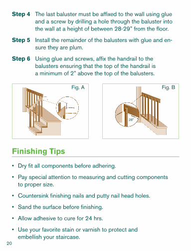
Step 10 Using glue and screws, affix the handrail to the balusters ensuring that the top of the handrail is a minimum of 2” above the top of the balusters.
Step 11 Butt the handrail to the face of the long baluster on the landing, ensuring that the top of the handrail is flush with the bevil of the baluster.
Step 12 Screw the handrail to the baluster as shown (p.20 Fig.A).
Hallway Installation
Step 1 Mark centre point of each baluster using the calculated “Distance between balusters”.
Step 2 If using dowel pin to secure baluster to floor, drill a ¾” by 1” deep hole for each baluster centre.
Step 3 Measure and cut the handrail to the appropriate length.
20
• Dry fit all components before adhering.
• Pay special attention to measuring and cutting components to proper size.
• Countersink finishing nails and putty nail head holes.
• Sand the surface before finishing.
• Allow adhesive to cure for 24 hrs.
• Use your favorite stain or varnish to protect and embellish your staircase.
Finishing Tips
Step 4 The last baluster must be affixed to the wall using glue and a screw by drilling a hole through the baluster into the wall at a height of between 28-29” from the floor.
Step 5 Install the remainder of the balusters with glue and en-sure they are plum.
Step 6 Using glue and screws, affix the handrail to the balusters ensuring that the top of the handrail is a minimum of 2” above the top of the balusters.
28"
Fig. A Fig. B

21
AccessoriesWall Mount Rosette
Stair Tread
Stair Tread Bullnose Cap
Wall Mount Rosette
Handrail
Wall Mount Rosette
HandrailUsed when installing a handrail to a wall.
Used to finish off an end of a stair tread that is visible.
Decorative addition for handrail ending at a wall as well for the handrail bracket.
Handrail Bracket
Stair Tread Bullnose Cap
22
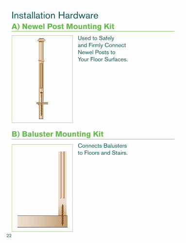
Installation HardwareA) Newel Post Mounting Kit
Used to Safely and Firmly Connect Newel Posts to Your Floor Surfaces.
B) Baluster Mounting KitConnects Balusters to Floors and Stairs.

23
C) Handrail & Newel Post ConnectorConnects:
Handrail to Newel PostNewel Post to Stair Riser
D) Handrail – Bolt ConnectorConnects:
Handrail to Newel PostHandrail to WallHandrail to Handrail

24
E) Newel Post Mounting PlateSecurely Fastens Newel Post to Floor.

25
Visual GlossaryThe detailed glossary below illustrates examples of the different parts that make up a staircase as well as their individual function. For a complete parts listing, call your local home improvement retailer.
Note: Please check with your local building codes before starting any installation.
Handrail
Modern Handrail
Handrail attaches to side of balusters rather than on top of them.
Shoerail
A strip running along the floor for insertion of balusters.
Handrail without Fillet
Used for wall mounted applications or with wrought iron balusters.
Handrail with Fillet
Used when wood balusters are to be inserted into the plow.
Fillet
Shoerail Shoerail
Fillet
Balusters
Modern Handrail
Balusters
Handrail
Handrail
Handrail
Fillet
Plow

26
Newel Posts
Half Newel Post
Used when handrail ends at a wall.
Newel Post
Used at beginning and end of handrail and every time handrails changes direction.
27
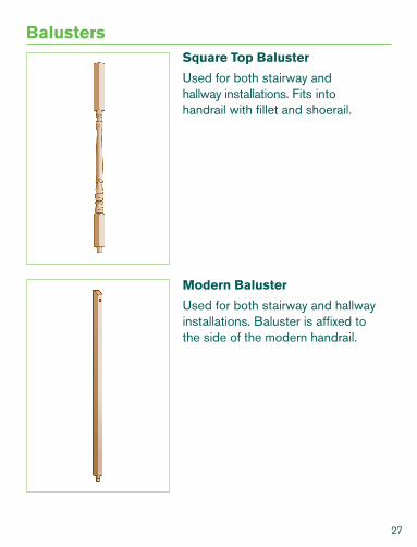
BalustersSquare Top Baluster
Used for both stairway and hallway installations. Fits into handrail with fillet and shoerail.
Modern Baluster
Used for both stairway and hallway installations. Baluster is affixed to the side of the modern handrail.

28
Wrought Iron Panels
Used with handrails without fillet.HallwayStairway
Wrought Iron Balusters
Used with handrails without fillet.HallwayStairway
Others
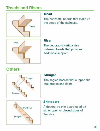
Treads and Risers
Skirtboard
A decorative trim board used on either open or closed sides of the stair.
Stringer
The angled boards that support the stair treads and risers.
Tread
The horizontal boards that make up the steps of the staircase.
Riser
The decorative vertical rise between treads that provides additional support.
Stringer
Stringer
Stringer
Skirtboard
Riser
Tread
29

30
Tools and Hardware Required
• Phillips screw driver
• Hand saw
• Level
• Masking tape
• Construction adhesive
• 8 screws per panel baluster
• Caulk
Installation Guide
Step 1 Balusters are installed so the distance between each does not exceed 4”. There is typically one panel baluster per tread.
Step 2 Mark the location of the center of each panel baluster on the stair treads. Refer to Newel Post Installation section for details on constructing a baluster line.
Step 3 Before installing panel baluster, ensure the removable cap is on the post. See *TIPS AND TRICKS.
Step 4 Beginning at the bottom of the staircase, install the panel balusters by affixing them to the treads first with the screws provided.
Urban Wrought Iron Balusters Installation
31
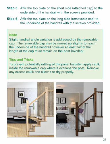
Step 5 Affix the top plate on the short side (attached cap) to the underside of the handrail with the screws provided.
Step 6 Affix the top plate on the long side (removable cap) to the underside of the handrail with the screws provided.
NoteSlight handrail angle variation is addressed by the removable cap. The removable cap may be moved up slightly to reach the underside of the handrail however at least half of the length of the cap must remain on the post (overlap).
Tips and TricksTo prevent potentially rattling of the panel baluster, apply caulk inside the removable cap where it overlaps the post. Remove any excess caulk and allow it to dry properly.

32
Product Installation Features
• Two top newel extensions are provided to accommodate both stairway and hallway installation heights.
• Top swiveling mounting plate allows for ease of in-stallation on both staircase and hallway applications accommodating virtually any handrail angles.
• Top swiveling mounting plate incorporates angled countersunk screw holes for easy tool access.
• Thick metal anchoring brackets for reliable installa-tion
Aluminum Newel Post Installation
Note
3.3/16”
3.3/1
6”
The following instructions are for a typical staircase with a 9” run, 7.1/2” rise and 1.1/2” nosing (measured from the front edge of the tread to the face of the riser). Any other variations need to meet local building code. It is important to ensure there is proper structural support under the newel post and /or any location where the handrail is attached to a wall.

33
3.3/16”
3.3/1
6”
3.3/16”
3.3/1
6”
Step 1 Locate Starting Newel Post Position
To determine the exact location of the starting newel post on the starting tread, the center of the newel should be 3.3/16” from the nosing edge of the starting tread and 3.3/16” from the side of the starting tread. Mark the center position of the newel on the starting tread.
• Draw two extended lines parallel to the front and the side of the starting tread intersecting at the point that marks the center position identified above.
• Line up the centering lines on the anchor bracket with the extended lines drawn above.
• Drill an appropriate pilot hole into the tread and the structural support beneath for each screw hole on the anchor bracket.
• Use fasteners appropriate for your application. (fasteners not included).
• Fasten newel post to the starting tread.
• Make sure that the longer newel extension is used for the starting newel and the shorter extension for the landing newel.

34
Step 2 Locate Landing Newel Post Position
To determine the exact location of the landing newel post on the landing, the center of the newel should be 3.3/16” from the nosing edge of the landing and lined up with the starting newel post. Mark the center position of the newel on the landing.
(Note: The line between the center of the starting newel and the center of the landing newel forms the baluster line.)
• Draw one extended line parallel to the front of the nosing edge of the landing and one extended line along the baluster line that intersects at the point that marks the center position identified above.
• Line up the centering lines on the anchor bracket with the extended lines drawn above.
• Drill an appropriate pilot hole into the tread and the structural support beneath for each screw hole on the anchor bracket.
• Use fasteners appropriate for your applications (fas-teners not included).
• Fasten newel post to the landing.
3.3/16”
3.3/1
6”

35
• Make sure that the longer newel extension is used for the starting newel and the shorter extension for the landing newel.
Step 3 Install Handrail
It is strongly advised to use a scrap piece of wood (e.g. 2”x4” lumber) in place of the actual handrail to determine the angle setup of the miter saw for cut-ting the stairway handrail.
See instructions below:
• Lay a section of 2”x4” lumber across the tread nos-ing (make sure the 2”x4” is long enough to touch at least 3 tread nosings on the staircase) and secure with a clamp to the top newel post. Identify this piece as stairway.
• Lay a section of 2”x4” lumber on the landing next to the 2”x4” on the staircase. Identify this piece as hallway. (Make sure the two pieces of 2”x4” overlap each other).
Hallway 2”x4”
Stairw
ay 2”x4
”

36
• Mark a line where the top of both 2”x4”’s meet. Mark another line where the bottom of both 2”x4”’s meet. Draw a straight line on each 2”x4” between the top and the bottom marks.
• Use these two pieces of 2”x4” as the template to determine the miter saw angle.
• Once the angle is determined, you can now cut the ends where your stairway and hallway 2”x4”’s join. Dry fit the 2”x4”’s together to ensure proper align-ment. A slight adjustment to the angle of the saw may be required if the initial dry fit test does not give an acceptable alignment.
• If the joint alignment is satisfactory, trim the ends of the actual handrails to suit your application and securely fasten the hallway and stairway handrails together.
• Handrail fasteners not included.
Hallway 2”x4”Point where handrails meet on the top
Point where handrails meet on the bottom
Stairw
ay 2”x4
”
Stairway 2”x4” Hallway 2”x4”

37
Balusters are installed so the distance between each does not exceed 4”. There are typically two balusters per tread. A long baluster is used for the back of each tread and a short baluster is used for the front of each tread. Due to the fact that our balusters are adjustable in height, the same baluster type can be used for both the back and the front of each tread.
Product Installation Features
• Thanks to the patent pending unique bottom swivel design of our Adjustable Aluminum Baluster, this baluster can be used on both “flat tread” and/or “angled stringer” installation.
• Top swiveling mounting plate allows for ease of in-stallation on both staircase and hallway applications accommodating virtually any handrail angles.
• Top swiveling mounting plate incorporates angled countersunk holes for easy tool access.
• Patented height-adjustability design fits virtually any handrail height.
Adjustable Aluminum Baluster Installation
3.3/16”
3.3/1
6”

38
NoteThe following instructions are for a typical staircase with a 9” run, 7.1/2” rise and 1.1/2” nosing (measured from the front edge of the tread to the face of the riser). Any other variations need to meet local building code. It is important to ensure there is proper structural support under the newel post and /or any location where the handrail is attached to a wall.
Step 1 Locate the Baluster Position (assuming newel posts and the handrails are previ-ously installed)
• Construct a baluster line by drawing a line on each tread through the center of both newel posts. Bal-usters and newel posts are all centered along the same baluster line.
• Each baluster comes with two bottom swivel caps. One specifically designed for “flat tread” installation and the other for “angled stringer” installation.
Flat tread AngledStringer

39
Newel Post
Newel Post
• To determine the exact location of the balusters on the stair tread, the center of each front baluster should be 1.5” + one half the width of the baluster from the nosing edge of the stair tread (this would exclude the starting tread if the newel is installed on it). Mark the center position of each front baluster.
• The center of each back baluster should be posi-tioned 4.5” from the center of the front baluster. Mark the center position of each back baluster.
13/1
6”1.Front Baluster
Center
1/2”
4.
Front Baluster CenterFront Baluster Center
Back Baluster Center

40
Step 2 Fastening the Bottom of the Baluster to Tread
• Remove the bottom swivel cap with offset cut-out (only used for stringer installation). Keep the bottom swivel cap with the center cut-out on the bottom tube.
• Make sure the bottom tube stays inserted in the top tube.
• Make sure the screw holes on the bottom swivel are in line with the baluster line.
• Line up the center of the baluster tube with the center marks identified in Step 1.
• Mark the position of the swivel holes. Drill an ap-propriate pilot hole for each swivel holes.
• Fasten the baluster into the tread using the screws provided.
• To prevent the bottom swivel cover from moving, it is recommended that a small amount of clear silicon be applied between the tread and the bottom of the cover.
Step 3 Fastening the top of the Baluster to the Handrail
• Extend the top tube until the swivel rests against the underside of the handrail. Using a level, make sure that the baluster is leveled in both directions. Tighten the set screw to lock the height of the baluster.

41
Set Screw
Allen Key
• Mark the position of the swivel holes on the under-side of the handrail. Drill an appropriate pilot hole for each swivel hole.
( Note: Swivel holes are countersunk and at an angle to facilitate easy access of a power tool.)
• Fasten the baluster to the handrail.
Repeat Step 2 and 3 until all the balusters are installed.
Balusters are installed so the distance between each does not exceed 4”. There are typically two balusters per tread. A long baluster is used for the back of each tread and a short balus- ter is used for the front of each tread. The design of this kit allows for virtu- ally any height of baluster due to the fact that the wood component can be cut to the required height. The same Hybrid Baluster Kit can be used for both the back and the front of each tread. This patent pending product provides multiple design pos-sibilities. You may select your preferred wood species and finish to your own taste prior to assembly.
Hybrid Baluster Kit Installation
42
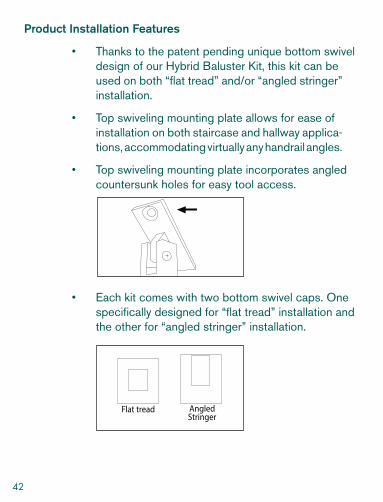
Product Installation Features
• Thanks to the patent pending unique bottom swivel design of our Hybrid Baluster Kit, this kit can be used on both “flat tread” and/or “angled stringer” installation.
• Top swiveling mounting plate allows for ease of installation on both staircase and hallway applica-tions, accommodating virtually any handrail angles.
• Top swiveling mounting plate incorporates angled countersunk holes for easy tool access.
• Each kit comes with two bottom swivel caps. One specifically designed for “flat tread” installation and the other for “angled stringer” installation.
3.3/16”
3.3/1
6”
Flat tread AngledStringer

43
NoteThe following instructions are for a typical staircase with a 9” run, 7.1/2” rise and 1.1/2” nosing (measured from the front edge of the tread to the face of the riser). Any other variations need to meet local building code. It is important to ensure there is proper structural support under the newel post and /or any location where the handrail is attached to a wall.
Step 1 Kit Assembly ( assuming newel posts are previously installed)
For each baluster, determine the required height of the wood component (please take into account the recess in the metal caps that cover the wood component).
• Cut the wood to length making sure that the ends of the wood are cut square.
• Remove the cardboard piece from the kit assembly.
• Place the metal caps over the wood component. Mark the screw hole and drill appropriate pilot hole as straight as possible into the wood (min. 1.1/4” deep).
(drill min. 1.1/4” deep)
Metal Cap
Wood Component
Mark Screw Hole

44
• Unscrew both swivels from the extensions of the kit (top and bottom).
• For both the top and bottom components of the kit, drop the provided wood screw through the extension making sure the screw comes out of the bottom. Attach the metal cap to the extension. Insert the wood component into the cap and fasten the screw into the wood component. It is recom-mended to use a power drill with an extended bit.
• Reassemble the top swivel.
• Prior to reassembling the bottom swivel, ensure the proper bottom swivel cover is chosen for either stringer application or tread application.
• For tread application, slide the bottom swivel cap with the center cut-out on the bottom extension.
Metal Cap
Wood Component
Extension
Flat tread AngledStringer

45
• For stringer application, slide the bottom swivel cap with offset cut-out on the bottom extension.
• Reassemble the bottom swivel.
Step 2 Locate the Baluster Position ( assuming newel posts and handrail are previously installed)
• Construct a baluster line by drawing a line on each tread through the center of both newel posts. Bal-usters and newel posts are all centered along the same baluster line.
• To determine the exact location of the balusters on the stair tread, the center of each front baluster should be 1.5” + one half the width of the baluster from the nosing edge of the stair tread (this would exclude the starting tread if the newel is installed on it). Mark the center position of each front baluster.
Newel Post
Newel Post
Front Baluster Center
1/8”
2.

46
• The center of each back baluster should be posi-tioned 4.5” from the center of the front baluster. Mark the center position of each back baluster.
Step 3 Fastening the Bottom of the Baluster to Tread ( assuming newel posts and handrail are previously installed)
• Make sure the screw holes on the bottom swivel are in line with the baluster line.
• Line up the center of the baluster tube with the center marks identified in Step 2.
• Mark the position of the swivel holes. Drill an ap-propriate pilot hole for each swivel holes.
• Fasten the baluster into the tread using the screws provided.
• To prevent the bottom swivel cover from moving, it is recommended that a small amount of clear silicon be applied between the tread and the bottom of the cover. Handrail fasteners not included.
1/2”
4.
Front Baluster Center
Front Baluster Center
Back Baluster Center

47
Step 4 Fastening the Top of the Baluster to the Handrail
• Rest the top swivel against the underside of the handrail. Using a level, make sure that the baluster is leveled in both directions.
• Mark the position of the swivel holes on the under-side of the handrail. Drill an appropriate pilot hole for each swivel hole. Fasten the baluster to the handrail.
(Note: Swivel holes are countersunk and at an angle to facilitate easy access of a power tool.)
Repeat Step 3 and 4 until all the balusters are installed.

Enhance Your Stairwaywww.alexandriamoulding.com