Stainless Steel Ball and Stem
6
Technical data sheet B253 www.belimo.com B253 • en-us • 2021-08-16 • Subject to change 1 / 3 • Application Stainless Steel Ball and Stem Technical data Functional data Valve Size 2" [50] Fluid chilled or hot water, up to 60% glycol Fluid Temp Range (water) 0...250°F [-18...120°C] Body Pressure Rating 400 psi Close-off pressure ∆ps 200 psi Flow characteristic equal percentage Servicing maintenance-free Flow Pattern 2-way Leakage rate 0% for A – AB Controllable flow range 75° Cv 120 Cv Flow Rating A-port: as stated in chart B-port: 70% of A – AB Cv Materials Valve body Nickel-plated brass body Spindle stainless steel Spindle seal EPDM (lubricated) Seat PTFE Characterized disc stainless steel Pipe connection NPT female ends O-ring EPDM (lubricated) Ball stainless steel Suitable actuators Non-Spring ARB(X) Spring AFRB(X) Safety notes WARNING: This product can expose you to lead which is known to the State of California to cause cancer and reproductive harm. For more information go to www.p65warnings.ca.gov Product features This valve is typically used in air handling units on heating or cooling coils, and fan coil unit heating or cooling coils. Some other common applications include Unit Ventilators, VAV box re- heat coils and bypass loops. This valve is suitable for use in a hydronic system with variable flow.
Transcript of Stainless Steel Ball and Stem
Technical data sheet B253
www.belimo.com B253 • en-us • 2021-08-16 • Subject to change 1 / 3
•
Application
Stainless Steel Ball and Stem
Technical data
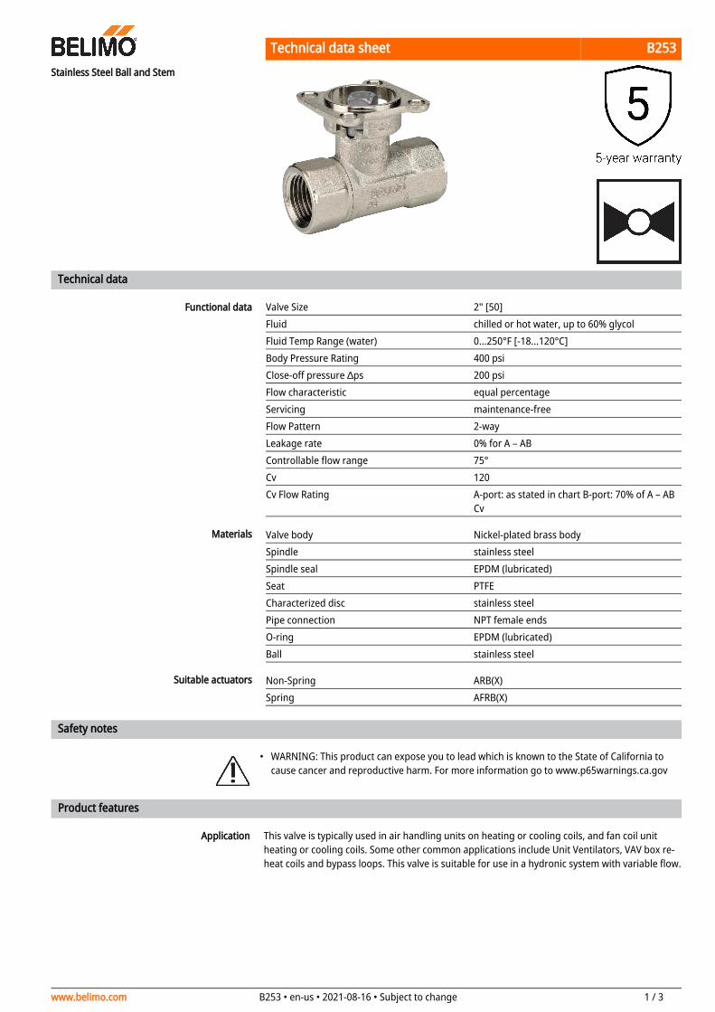
Functional data Valve Size 2" [50]Fluid chilled or hot water, up to 60% glycolFluid Temp Range (water) 0...250°F [-18...120°C]Body Pressure Rating 400 psiClose-off pressure ∆ps 200 psiFlow characteristic equal percentageServicing maintenance-freeFlow Pattern 2-wayLeakage rate 0% for A – ABControllable flow range 75°Cv 120 Cv Flow Rating A-port: as stated in chart B-port: 70% of A – AB
Cv
Materials Valve body Nickel-plated brass bodySpindle stainless steelSpindle seal EPDM (lubricated)Seat PTFECharacterized disc stainless steelPipe connection NPT female endsO-ring EPDM (lubricated)Ball stainless steel
Suitable actuators Non-Spring ARB(X)Spring AFRB(X)
Safety notes
WARNING: This product can expose you to lead which is known to the State of California to cause cancer and reproductive harm. For more information go to www.p65warnings.ca.gov
Product features
This valve is typically used in air handling units on heating or cooling coils, and fan coil unit heating or cooling coils. Some other common applications include Unit Ventilators, VAV box re-heat coils and bypass loops. This valve is suitable for use in a hydronic system with variable flow.

Technical data sheet B253
www.belimo.com B253 • en-us • 2021-08-16 • Subject to change 2 / 3
Flow/Mounting details
Two-way valves should be installed with the disc upstream.
Dimensions
Dimensional drawings
ARB, ARX
A B C D E F H111.3" [286] 4.9" [125] 7.7" [196] 6.0" [152] 1.7" [44] 1.7" [44] 1.2" [30]
ARB N4, ARX N4, NRB N4, NRX N4
A B C D E F11.4" [289] 4.9" [125] 9.8" [249] 7.6" [194] 3.1" [80] 3.1" [80]
ARQB, ARQX
A B C D E F H1 H29.9" [251] 4.9" [125] 7.5" [191] 6.1" [155] 2.3" [58] 2.3" [58] 0.8" [20] 0.6" [15]
AFRB, AFRX
A B C D E F11.3" [286] 4.9" [125] 10.6" [268] 8.9" [225] 2.0" [51] 2.0" [51]

Technical data sheet B253
www.belimo.com B253 • en-us • 2021-08-16 • Subject to change 3 / 3
AFRB N4, AFRX N4
A B C D E F13.0" [330] 4.9" [125] 10.3" [262] 9.3" [235] 3.4" [86] 3.4" [86]

Technical data sheet AFRX24-MFT N4
www.belimo.us AFRX24-MFT N4 • en-us • 2021-08-17 • Subject to change 1 / 3
NEMA 4, Modulating, Spring Return, Direct Coupled, 24 V, Multi-Function Technology®
Technical data
Electrical data Nominal voltage AC/DC 24 VNominal voltage frequency 50/60 HzPower consumption in operation 7.5 WPower consumption in rest position 3 WTransformer sizing 10 VA (class 2 power source)Electrical Connection 18 GA appliance cable, 3 ft [1 m], with 1/2"
conduit connectorOverload Protection electronic throughout 0...95° rotation
Functional data Operating range Y 2...10 VOperating range Y note 4...20 mA w/ ZG-R01 (500 Ω, 1/4 W resistor)Input Impedance 100 kΩ for 2...10 V (0.1 mA), 500 Ω for 4...20
mA, 1500 Ω for PWM, On/Off and Floating pointOperating range Y variable Start point 0.5...30 V
End point 2.5...32 VOptions positioning signal variable (VDC, PWM, on/off, floating point)Position feedback U 2...10 VPosition feedback U note Max. 0.5 mAPosition feedback U variable VDC variableDirection of motion motor selectable with switchDirection of motion fail-safe reversible with cw/ccw mountingManual override 5 mm hex crank (3/16" Allen), suppliedAngle of rotation 90°Running Time (Motor) default 150 s, variable 70...220 sRunning time motor variable 70...220 sRunning time fail-safe <20 sAngle of rotation adaptation off (default)Override control MIN (minimum position) = 0%
MID (intermediate position) = 50%MAX (maximum position) = 100%
Noise level, motor 45 dB(A)Noise level, fail-safe 62 dB(A)Position indication Mechanical
Safety data Degree of protection IEC/EN IP66Degree of protection NEMA/UL NEMA 4XEnclosure UL Enclosure Type 4XAgency Listing cULus acc. to UL60730-1A/-2-14, CAN/CSA
E60730-1:02, CE acc. to 2014/30/EU and 2014/35/EU
Quality Standard ISO 9001Ambient temperature -22...122°F [-30...50°C]

Technical data sheet AFRX24-MFT N4
www.belimo.us AFRX24-MFT N4 • en-us • 2021-08-17 • Subject to change 2 / 3
•
Safety data Storage temperature -40...176°F [-40...80°C]Ambient humidity Max. 100% RHServicing maintenance-free
Safety notes
The valves should be mounted in a weather-protected area in a location that is within the ambient limits of the actuator. Allow sufficient room for valve with actuator and for service. The G2(S) and G3(D) preferred mounting position of the valve is with the valve stem vertical above the valve body, for maximum life. However, the assemblies can be mounted with the valve stem vertical or horizontal in relation to the pipe. The actuators should never be mounted underneath the valve, as condensation can build up and result in a failure of the actuators. Do not reverse flow direction.
Accessories
Gateways Description TypeGateway MP to BACnet MS/TP UK24BACGateway MP to Modbus RTU UK24MODGateway MP to LonWorks UK24LON
Electrical accessories Description TypeService Tool, with ZIP-USB function, for programmable and communicative Belimo actuators, VAV controller and HVAC performance devices
ZTH US
Service tools Description TypeConnection cable 10 ft [3 m], A: RJ11 6/4 ZTH EU, B: 3-pin Weidmüller and supply connection
ZK4-GEN
Service Tool, with ZIP-USB function, for programmable and communicative Belimo actuators, VAV controller and HVAC performance devices
ZTH US
Electrical installation
INSTALLATION NOTESActuators with appliance cables are numbered.Provide overload protection and disconnect as required.Actuators may also be powered by DC 24 V.Only connect common to negative (-) leg of control circuits.A 500 Ω resistor (ZG-R01) converts the 4...20 mA control signal to 2...10 V.Control signal may be pulsed from either the Hot (Source) or Common (Sink) 24 V line.For triac sink the Common connection from the actuator must be connected to the Hot connection of the controller. Position feedback cannot be used with a triac sink controller; the actuator internal common reference is not compatible.IN4004 or IN4007 diode. (IN4007 supplied, Belimo part number 40155).Actuators may be controlled in parallel. Current draw and input impedance must be observed.Master-Slave wiring required for piggy-back applications. Feedback from Master to control input(s) of Slave(s).Meets cULus requirements without the need of an electrical ground connection.Warning! Live electrical components!During installation, testing, servicing and troubleshooting of this product, it may be necessary to work with live electrical components. Have a qualified licensed electrician or other individual who has been properly trained in handling live electrical components perform these tasks. Failure to follow all electrical safety precautions when exposed to live electrical components could result in death or serious injury.

Technical data sheet AFRX24-MFT N4
www.belimo.us AFRX24-MFT N4 • en-us • 2021-08-17 • Subject to change 3 / 3
Wiring diagramsOn/Off Floating Point
VDC/mA Control PWM Control
Override Control Master - Slave
Dimensions