STAFF User Manual - Rycom Instruments® Utility Locators - · PDF file ·...
11
Manual Part # 030-00085-00 STAFF User Manual
Transcript of STAFF User Manual - Rycom Instruments® Utility Locators - · PDF file ·...

Manual Part # 030-00085-00
STAFF User Manual

800.851.7347 www.rycominstruments.com
800.851.7347 www.rycominstruments.com
Introduction Congratulations on the purchase of your new STAFF Secondary Fault Locator. The STAFF is specially designed to detect conductor to earth/ground faults in buried conductors.
The TransmiTTer emits a signal. The receiver detects the signal. You can locate the rel-ative position of the buried utility, sonde or camera by following the tracing signal.
Prepare for Use
Unpack your newSTAFF Directional Fault Finder. Make sure there is no shipping damage and all the parts are included.
Locate the battery compartment inside the TransmiTTer. Remove the battery compartment door. Install the eight Duracell® “C” batteries as marked.
Locate the battery compartment on the back of the top tube of the STAFF. The cap unscrews counterclockwise. Insert the 6 "AA" Duracell® batteries according to the label with the corresponding terminal (+/-) facing up.
Note: For longer battery life and reliable operation under adverse conditions, use only Duracell® alkaline batteries.
2
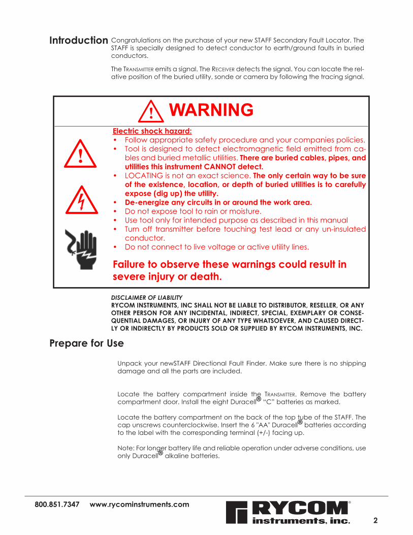
Electric shock hazard:• Follow appropriate safety procedure and your companies policies.• Tool is designed to detect electromagnetic field emitted from ca-
bles and buried metallic utilities. There are buried cables, pipes, and utilities this instrument CANNOT detect.
• LOCATING is not an exact science. The only certain way to be sure of the existence, location, or depth of buried utilities is to carefully expose (dig up) the utility.
• De-energize any circuits in or around the work area.• Do not expose tool to rain or moisture.• Use tool only for intended purpose as described in this manual• Turn off transmitter before touching test lead or any un-insulated
conductor.• Do not connect to live voltage or active utility lines.
Failure to observe these warnings could result in severe injury or death.
DISCLAIMER OF LIABILITYRYCOM INSTRUMENTS, INC SHALL NOT BE LIABLE TO DISTRIBUTOR, RESELLER, OR ANY OTHER PERSON FOR ANY INCIDENTAL, INDIRECT, SPECIAL, EXEMPLARY OR CONSE-QUENTIAL DAMAGES, OR INJURY OF ANY TYPE WHATSOEVER, AND CAUSED DIRECT-LY OR INDIRECTLY BY PRODUCTS SOLD OR SUPPLIED BY RYCOM INSTRUMENTS, INC.
WARNING
800.851.7347 www.rycominstruments.com
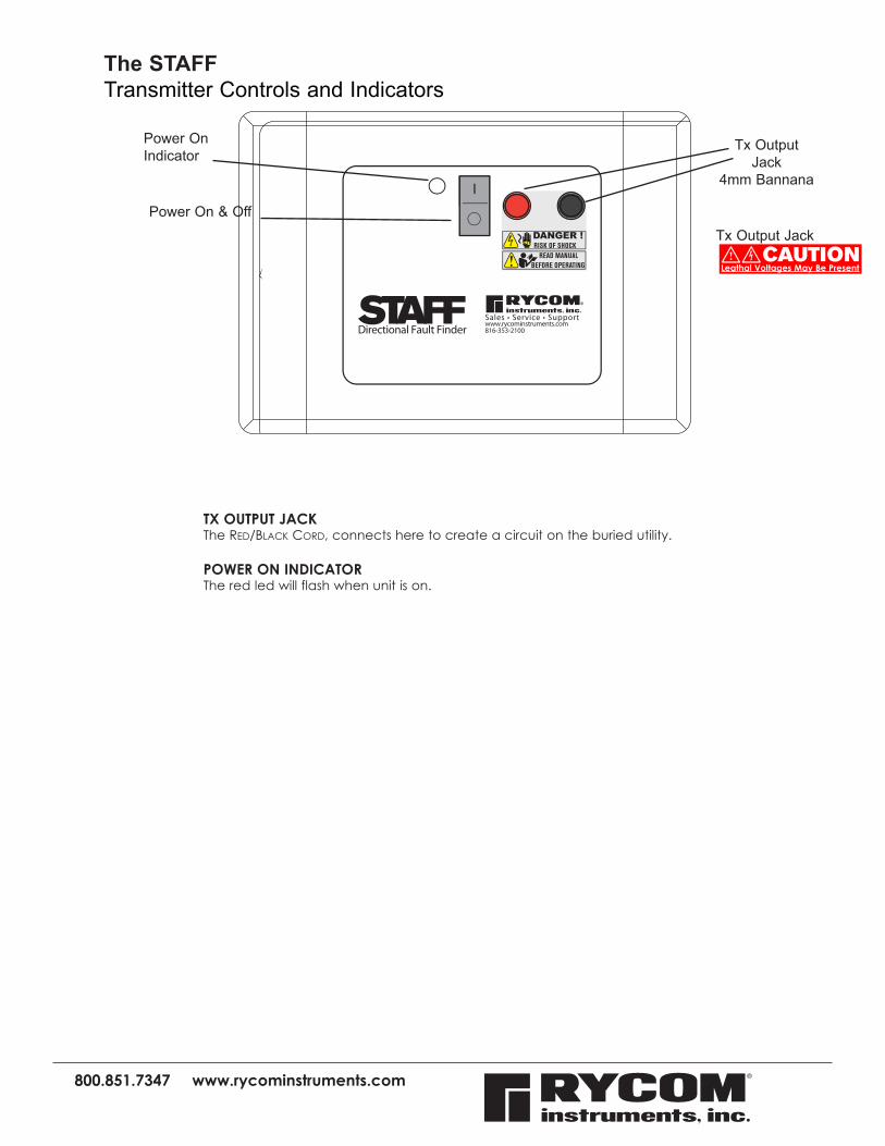
The STAFFTransmitter Controls and Indicators
TX OUTPUT JACKThe red/Black cord, connects here to create a circuit on the buried utility. POWER ON INDICATORThe red led will flash when unit is on.
Power On & Off8869
Power On Indicator
Tx OutputJack
4mm Bannana
Tx Output JackCAUTION
Leathal Voltages May Be Present
®
I
800.851.7347 www.rycominstruments.com
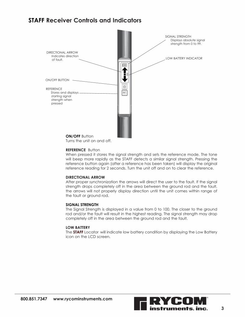
STAFF Receiver Controls and Indicators
ON/OFF ButtonTurns the unit on and off.
REFERENCE ButtonWhen pressed it stores the signal strength and sets the reference mode. The tone will beep more rapidly as the STAFF detects a similar signal strength. Pressing the reference button again (after a reference has been taken) will display the original reference reading for 2 seconds. Turn the unit off and on to clear the reference.
DIRECTIONAL ARROWAfter proper synchronization the arrows will direct the user to the fault. If the signal strength drops completely off in the area between the ground rod and the fault, the arrows will not properly display direction until the unit comes within range of the fault or ground rod. SIGNAL STRENGTHThe Signal Strength is displayed in a value from 0 to 100. The closer to the ground rod and/or the fault will result in the highest reading. The signal strength may drop completely off in the area between the ground rod and the fault.
LOW BATTERYThe STAFF Locator will indicate low battery condition by displaying the Low Battery icon on the LCD screen.
3
ON/OFF BUTTON
DIRECTIONAL ARROW Indicates direction
of fault.
SIGNAL STRENGTH Displays absolute signal
strength from 0 to 99.
REFERENCE Stores and displays
starting signal strength when pressed
LOW BATTERY INDICATOR
800.851.7347 www.rycominstruments.com
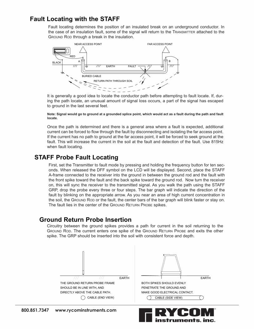
It is generally a good idea to locate the conductor path before attempting to fault locate. If, dur-ing the path locate, an unusual amount of signal loss occurs, a part of the signal has escaped to ground in the last several feet.
Note: Signal would go to ground at a grounded splice point, which would act as a fault during the path and fault locate.
Once the path is determined and there is a general area where a fault is expected, additional current can be forced to flow through the fault by disconnecting and isolating the far access point. If the current has no path to ground at the far access point, it will be forced to seek ground at the fault. This will increase the current in the soil at the fault and detection of the fault. Use 815Hz when fault locating.
Fault Locating with the STAFFFault locating determines the position of an insulated break on an underground conductor. In the case of an insulation fault, some of the signal will return to the TransmiTTer attached to the Ground rod through a break in the insulation.
BURIED CABLE
FAULT
RETURN PATH THROUGH SOIL
A B
NEAR ACCESS POINT FAR ACCESS POINT
EARTHBLACK
RED
Ground Return Probe InsertionCircuitry between the ground spikes provides a path for current in the soil returning to the Ground rod. The current enters one spike of the Ground reTurn Probe and exits the other spike. The GRP should be inserted into the soil with consistent force and depth.
EARTH EARTH
CABLE (END VIEW)
THE GROUND RETURN PROBE FRAMESHOULD BE IN LINE WITH, ANDDIRECTLY ABOVE THE CABLE PATH.
CABLE (SIDE VIEW)
BOTH SPIKES SHOULD EVENLYPENETRATE THE GROUND ANDMAKE GOOD ELECTRICAL CONTACT.
First, set the Transmitter to fault mode by pressing and holding the frequency button for ten sec-onds. When released the DFF symbol on the LCD will be displayed. Second, place the STAFF A-frame connected to the receiver into the ground in between the ground rod and the fault with the front spike toward the fault and the back spike toward the ground rod. Now turn the receiver on, this will sync the receiver to the transmitted signal. As you walk the path using the STAFF GRP, drop the probe every three or four steps. The bar graph will indicate the direction of the fault by blinking on the appropriate arrow. As you near an area of high current concentration in the soil, the Ground rod or the fault, the center bars of the bar graph will blink faster or stay on. The fault lies in the center of the Ground reTurn Probe spikes.
STAFF Probe Fault Locating

800.851.7347 www.rycominstruments.com
1) Locate path of faulted conductor2) Remove power from faulted conductor 3) Disconnect loads and ground from both ends of target conductor and neighboring conductors
4) With transmitter off connect red lead to the faulted conductor and black lead to independent ground rod5) Turn the transmitter on6) Complete transmitter instruction before using GRP7) Place GRP in soil with back spike approx. 2 yards from ground rod and front spike toward suspected fault 8) Turn receiver on (for proper synchronizing spikes must be in the ground before turning the unit to DFF mode.)9) Using mode button toggle the mode out of DFF and then through the modes until DFF is displayed again on LCD. 10) Note numeric reading as reference to signal strength near fault 11) LCD will indicate fault direction
12) Signal strength will fall as leaving the ground spike until passing the half-way point between ground spike and fault. Signal will start to rise from half-way point to fault. If the distance is great the signal strength may fall to non-detectable level and arrows may not stabilize through the center section.
99 78 61 54 40 15 ---- --- 15 40 54 61 78 99
13) Any synchronizing must be done near the ground rod with the spike in the ground before turning the unit to FF mode.
2 Meter Aprox.
Fault Locating with the 8880 STAFF
800.851.7347 www.rycominstruments.com
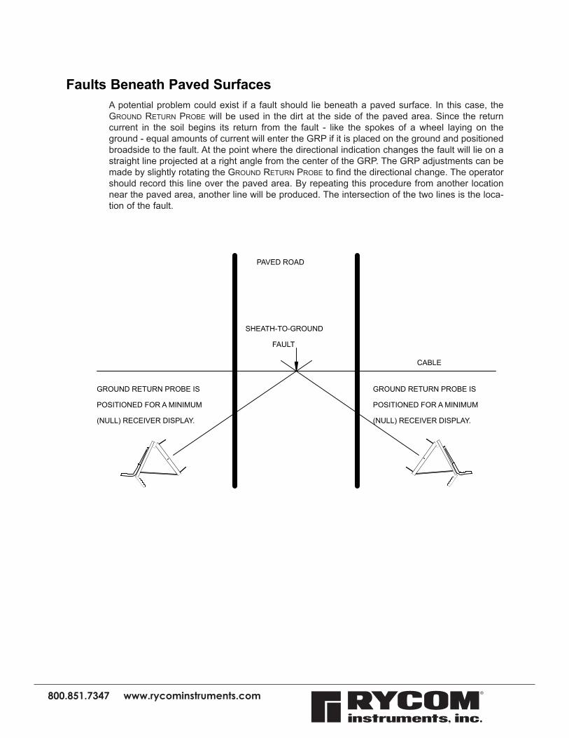
A potential problem could exist if a fault should lie beneath a paved surface. In this case, the Ground reTurn Probe will be used in the dirt at the side of the paved area. Since the return current in the soil begins its return from the fault - like the spokes of a wheel laying on the ground - equal amounts of current will enter the GRP if it is placed on the ground and positioned broadside to the fault. At the point where the directional indication changes the fault will lie on a straight line projected at a right angle from the center of the GRP. The GRP adjustments can be made by slightly rotating the Ground reTurn Probe to find the directional change. The operator should record this line over the paved area. By repeating this procedure from another location near the paved area, another line will be produced. The intersection of the two lines is the loca-tion of the fault.
Faults Beneath Paved Surfaces
CABLE
PAVED ROAD
GROUND RETURN PROBE IS
POSITIONED FOR A MINIMUM
(NULL) RECEIVER DISPLAY.
GROUND RETURN PROBE IS
POSITIONED FOR A MINIMUM
(NULL) RECEIVER DISPLAY.
SHEATH-TO-GROUND
FAULT
800.851.7347 www.rycominstruments.com
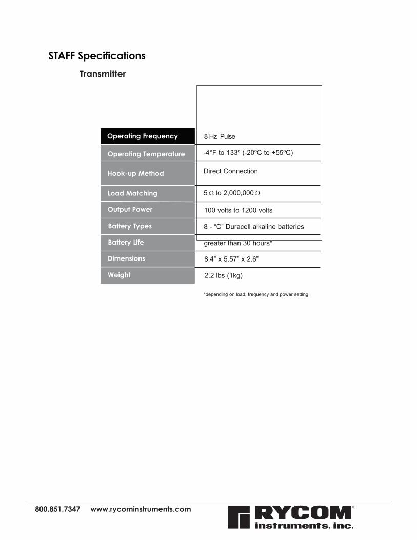
Transmitter
STAFF Specifications
Operating Frequency
Hook-up Method
Output Power
Load Matching
Battery Types
Dimensions
Weight
8 Hz Pulse
5 Ω to 2,000,000 Ω
Operating Temperature -4°F to 133º (-20ºC to +55ºC)
Battery Life greater than 30 hours*
100 volts to 1200 volts
8 - “C” Duracell alkaline batteries
8.4” x 5.57” x 2.6”
2.2 lbs (1kg)
*depending on load, frequency and power setting
Direct Connection
800.851.7347 www.rycominstruments.com
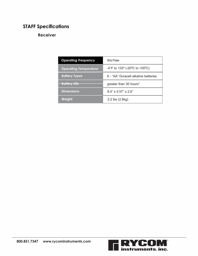
Receiver
STAFF Specifications
Operating Frequency
Battery Types
Dimensions
Weight
8Hz Pulse
Operating Temperature -4°F to 133º (-20ºC to +55ºC)
Battery Life greater than 30 hours*
6 - “AA” Duracell alkaline batteries
8.4” x 5.57” x 2.6”
2.2 lbs (2.8kg)

800.851.7347 www.rycominstruments.com
Factory ServiceIf your STAFF Locator is not working properly, first call RYCOM Instruments, Inc. Tech Support at 800-851-7347 for assistance. If the locator is in need of repair, Tech Support will provide instructions for sending your locator to the closest factory approved service center. The instrument will be repaired and shipped back or you will be advise if the instrument is un-repairable.
Note: There is a minimum charge for repair and handling.
WarrantyThis insTrumenT is under warranTy for one year from The daTe of delivery againsT defecTs in maTerial and workmanship (EXCEPT BATTERIES). we will repair or replace producTs ThaT prove To Be defecTive during war-ranTy period.
This warranTy is void if, afTer having received The insTrumenT in good con-diTion, iT is suBjecTed To aBuse, unauThorized alTeraTions or casual repair.
no oTher warranTy is expressed or implied. The warranTy descriBed in This paragraph shall Be in lieu of any oTher warranTy, including BuT noT limiTed To, any implied warranTy of merchanTaBiliTy or fiTness for a parTicular purpose. we are noT liaBle for consequenTial damages.