STACY KOPSO, M.ED., RT(R)(M) REFERENCES ODIA DIGITAL ACADEMY, ARRT HTTP:// Digital Imaging.
94
STACY KOPSO, M.ED., RT(R)(M) REFERENCES ODIA DIGITAL ACADEMY, ARRT HTTP://WWW.ONLINELEARNINGCENTER.COM Digital Imaging
-
Upload
shanon-cole -
Category
Documents
-
view
215 -
download
3
Transcript of STACY KOPSO, M.ED., RT(R)(M) REFERENCES ODIA DIGITAL ACADEMY, ARRT HTTP:// Digital Imaging.

STACY KOPSO, M.ED. , RT(R)(M)REFERENCES
ODIA DIGITAL ACADEMY, ARRTHTTP: / /
WWW.ONLINELEARNINGCENTER.COM
Digital Imaging

Advantages
Large Dynamic RangePost Processing
Independence of adjustments in brightness and contrast through window width and level
Image enhancement and analysis (CAD)Accurately labeled dataStorage (PACS)Ability to transmit data to remote sites

Dynamic Range
Large dynamic range Image receptor's ability to respond to different
exposure levels The number of signal values that the receptor is
capable of capturing. The greater the number of signal values that a
receptor is capable of capturing, the greater the receptor's dynamic range.

Exposure Latitude
The range of exposure values to the receptor that produce an acceptable range of densities for diagnostic purposes
Automatic rescaling is the reason the digital system can produce an image even when significant exposure errors occur
Underexposure of 50% or greater results in a mottled image or an image with the appearance of noise
Overexposure greater than 100% to 200% results in a loss of image contrast, depending on the exam that is performed
Digital imaging has greater latitude than film screen

Exposure Latitude


Exposure Indicator
Image brightness and contrast no longer are linked to exposure factors
Dose CreepTechnologists must use the exposure
indicator to determine if an image is properly exposed or within the acceptable range of under- or overexposure.
S# Scheiner's system index for exposure index German astronomer Julius Scheiner

Exposure Indicators for Cassette-Based
Fuji / Philips / KonicaS Number, Sensitivity Number Increase in exposure =decrease in S#
Carestream (Kodak) EI, Exposure Index Increase in exposure=increase in E
AgfalgM, Logarithm of a Histogram MedianIncrease in exposure=increase in IgM

Exposure Indicators for Flat Panel
Philips EIMeasures the speed class of operationIncreasing the exposure decreases the EI value
Siemens EXIDirectly related to the exposure levelIncreasing the exposure increases the EXI value
CanonREXDirectly related to the exposure level Increasing the exposure increases the REX value

Dose Area Product
Measures the entrance skin exposure delivered to the patient
Measured by detector inside or on collimatorCommonly employed with cassette-less
systemsDepends on exposure factors and field sizeReflects dose to patient and total volume of
tissue being irradiated

Detective Quantum Efficiency (DQE)
Efficiency of the detectorThe exposure level required to produce an imagePotential Speed class (similar to film)Higher DQE = lower pt dose (balance
dose/noise)A measure of how well the signal-to-noise ratio
(SNR) is preserved in an imageSNR is how clearly a very faint object appears in
an image. Signal (meaningful information) Noise
(background information)

Digital Receptors
Cassette-Based Systems Computed Radiography (CR)
Photostimulable Phosphor
Cassetteless Systems Digital Radiography (DR)
Photostimulable Phosphor Flat panel Charge-coupled device (CCD)


Cassette-Based Systems
Integrated with existing radiographic equipment AEC must be recalibrated and techniques must be
adjustedParts of a cassette-based system
Image receptor- Photostimulable phosphor plate (PSP) Plate reader Computer workstation

Photostimulable Phosphor Plate

Photostimulable Phosphor Plate

Photostimulable Plate
Protective layer Thin layer of plastic to protect the phosphor layer
Phosphor layer Barium fluorohalide Europium (activator) Turbid phosphor layer
Random distribution of phosphor crystals within the active layer
Structured phosphor layer Columnar phosphor crystals within the active layer

PSP Phosphor Layers
Turbid phosphor Columnar phosphor

Photostimulable Plate (cont’d)
Reflective layer Reflects light released during the reading phase
toward the photodetector Conductive layer
Reduces and conducts away static electricityColor layer
Absorbs stimulating light and reflect emitted lightSupport layer
Sturdy material to give rigidity to the plateBacking layer
Soft layer that protects the back of the plate

Characteristics of Photostimulable Phosphors
Characteristics of Photostimulable Phosphors
Characteristics of Photostimulable Phosphors
PSP Conversion Efficiency The ability of the storage phosphor to convert the
signal exiting the patient into trapped electrons.Absorption efficiency
A measure of how effective the phosphor is at absorbing the x-ray photons.

Photostimulable Phosphor Plate Response
PSP is exposed to x-raysPhosphor atoms are ionizedHalf of the removed electrons are “trapped”
in the conduction band (energy level of an atom)
These trapped electrons represent the latent image
PSP plate is exposed to the laser of the reader
Energy is released and converted to a digital signal
Becomes a manifest image


Erasure Lamp

Removes the rest of the trapped electronsGhost image
Insufficient erasure of an image

PSP Reader

Reader
Optical System Consists of a laser light, filters and beam-shaping
devicesDrive mechanism
Moves the PSP plate through the readerPhotodetector
Senses the light released from the PSP plate during scanning
This light is then sent to an analog-to-digital converter (ADC)
The ADC converts it to an electronic signal for the display computer

Light Guide Assembly
Directs the light that a PSP emits to a photomultiplier tube
The light guide collects the light and directs it back into a device called a photomultiplier tube. The tube converts the light into an electronic signal, which is digitized by the analog-to-digital converter, or ADC.

Light Guide Assemble

Plate Scanning
The laser beam scans across the plate which causes the electrons (elevated into F
traps by the x-ray beam) to drop back down into their normal orbit.
When those electrons drop back into their normal orbit, they emit light.
This light is directed to the photodetectorPhotodetector amplifies the light energy and
converts it to an electrical signalSignal is passes through an ADC where it is
digitized


Sampling
Time based event of the signal that is being sent from the photodetector to the ADC
Sampling frequency The number of pixels sampled per millimeter as the laser scans
each line of the imaging plateSampling pitch
How digital detectors sample the x-ray exposure Cassette-based
Distance between laser beam positions during processing of the plate
Cassetteless Distance between adjacent DELs

Spatial Resolution
The ability of an imaging system to allow two adjacent structures to be visualized as being separate, or the distinctness of an edge in the image (sharpness)
Limiting spatial resolutionThe ability of a detector to resolve small structures and is
measures using a bar patternModulation Transfer Function
Measure of the ability of the system to preserve signal contrast
Ideal expression of digital detector image resolution
Sampling Frequency
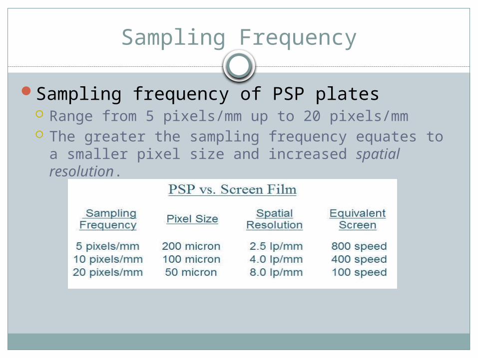
Sampling frequency of PSP plates Range from 5 pixels/mm up to 20 pixels/mm The greater the sampling frequency equates to a
smaller pixel size and increased spatial resolution.


Matrix
As the analog signal is digitized it is divided into a matrix
The detector size or field of view is the useful imaging area of the digital receptor
The size of the matrix determines the resolution
The larger the matrix, the greater the number of smaller pixels = increase in resolution
Disadvantage of larger matrix Computer processing time, transmission and digital
storage space increases as matrix increases

Pixel
Combination of rows and columns of pixels inside a matrix
Each matrix is a picture element known as a pixel
Each pixel is recorded as a single numerical value, which is represented as a single brightness level on the monitor
The numerical value is determined by the attenuation of xrays passing through the tissue
Bone, high attenuation=low value (increase brightness/decrease density)

Pixels
Each pixel has a bit depth (number of bits) that determines the exit radiation recorded
Controls the exact pixel brightness/shades of grayDetermined by the analog to digital converterLarge bit depth= greater number of shades of
gray displayedGreater shades of gray= better contrast
resolutionPixel pitch- distance between center of one pixel
and the center of an adjacent pixel (microns)

PSP Plate Scanning
Line Scan Used with cassette-less PSP The plate is either pulled underneath the linear
scanner or the plate remains stationary and the laser scanner moves across the plate.
Flying Spot Scan Cassette based A technologist inserts the plate, the plate moves
through the reader, and then during its movement, the laser beam moves across the plate.

Line Scan

Detective Quantum Efficiency (DQE)
Efficiency of the detector An expression of the exposure level required to produce an image. A measure of a receptor's ability to create an output signal that
accurately represents the input signal (x-ray beam). Expressed as the percentage of the x-ray energy that strikes the
receptor that is successfully converted to an output signal used in creating the image.
A measure of how well the signal-to-noise (SNR) ratio is preserved A receptor with a high DQE will require less dose to create an
optimal image when compared to a receptor with a low QE Referred to as potential speed

Pre-Processing

Histogram
The computer analyzes the histogram using processing algorithms
Compares it to a preestablished histogram specific to the anatomic part being imaged
These stored histogram models have values of interest
Computer identifies the exposure field and the edges of the image.
All exposure data outside this field are excluded from histogram

Histogram
Histograms graphically represent a collection of exposure values extracted from the receptor
Quantization-The number of bars that make up each histogram represents different sampling frequencies

Exposure Field Borders


INDIRECT AND DIRECT
Cassetteless Systems

Digital Radiography
A detector array replaces the bucky assemblyInstant viewingIndirect and direct capture
Indirect uses 2 forms of capture Charge Coupled Device (CCD) Scintillator

Indirect Capture
Two forms of captureEach form uses a scintillator
Charge Coupled device Thin-Film transistor

Charge Coupled Device (CCD)
Very light sensitiveCesium iodide phosphor plate connected to
CCD by fiberoptic (pg 159)Xrays are absorbed by the scintillator and
converted to lightLight is then transmitted to CCD where it is
converted to an electronic signal for viewingTiling- joins the CCD’s together

Charge Coupled Device
The light from scintillator material strikes the silicon in the CCD silicon chip. The electrons then are collected by the CCD chip elements we refer to as pixels.


Charge Coupled Device

Thin Film Transistor (TFT)
Uses cesium iodide or gadolinum oxysulfide as the phosphor
Photodetector amorphous silicon
TFT array Contains the readout, charge collector and light
sensitive elements Configured into a network of pixels/DEL’s covered by
the scintillator plate Each pixel contains a photodetector and transistor

Thin Film Transistors (TFT)
The transistor operates as a gateDuring an x-ray exposure, the gates are turned off,
the electric charge cannot flowThe image is built up in the dels in the form of an
electric chargeThe amount of charge in each del is proportional to
the number of x-rays absorbed in that region of the detector
Following the exposure, the “gates” are turned on one row at a time, and the amount of charge stored in each del is transferred for digitization and storage in the output digital matrix.

Thin Film Transistor (TFT)
X-ray energy is absorbed by the photodetectors and converted to electric charges
These charges are captured and transmitted by the TFT array to the workstation

Scintillator
Scintillator Absorbs xray energy and emits visible light in
response Material- Cesium iodide Converts the x-ray beam to light and then that light is
converted into electrons to create an image. Uses amorphous silicon as the photodetector and a
thin film transistor array (TFT) Indirect capture


Direct Capture

Direct Capture
Direct capture v (amorphous selenium) and a TFT array Converts the x-ray beam into electrons to create an
image Use amorphous selenium as the photoconductor to
convert the x-ray beam to electrons that thin film transistors (TFT) then collect
Better resolution than indirect


Flat Panel Image Receptors
Scintillator- uses amorphous silicon and a thin film transistor (TFT) array
Non-Scintillator-uses amorphous selenium and a TFT array

Detector Element
Each square in the matrix is a detector element (DEL). DELs collect the electrons given off by the amorphous selenium or the amorphous silicon


Detector Element
DELs collect electrons that are extracted from the detector assembly and converted into a digital value by an ADC.
That process creates the image that displays on our monitor. controls the recorded detail, or spatial resolution, for
the flat-panel device. fixed and set by manufacturer

Flat Panel Spatial Resolution
Determined by detector element size Fixed Increase the DEL size, you decrease spatial
resolution.

Flat Panel Spatial Resolution


Sampling Frequency & Spatial Resolution
Nyquist Frequency Determines the maximum spatial resolution for a given sampling
frequency.
Equals ½ of the sampling frequency. If 10 pixels/mm are scanned, Nyquist frequency is a maximum of 5lp/mm
Increasing the sampling frequency increases the time it takes to display a visual image.

Digital Image Characteristics
The digital image is a matrix of numbers, known as pixels, that corresponds to the intensity of the x-ray beam that strikes a particular area.

Pixels

Digital Image Spatial Resolution
Measured by the size of the pixel used to create an image.
The micron (µm) measures pixel size. 1 millimeter = 1 thousand micrometers
Digital Spatial Resolution
Matrix Size or Field of View Rows and columns of pixels Denser pixels within a fixed receptor size require a
larger image matrix to accommodate more squares within the image receptor.
If the receptor size increases with a fixed pixel size, more pixels of the same size must be added for a larger image matrix.

Digital Image Spatial Resolution
Pixel Size is measured from side to side of the pixel.
Pixel Pitch is measured from the center of one pixel to the center of an adjacent one.

Digital Image Spatial Resolution
Pixel density measures the number of pixels contained within a unit area.

Modulation Transfer Function
A measure of the ability of the system to preserve signal contrast as a function of spatial resolution
Ideal expression of digital detector image resolution

Image Characteristics
BrightnessContrastImage BlurImage NoiseSpatial Resolution

Post processing
Window Width The shade of gray displayed (contrast of the image)
Window Leveling Controls brightness/density
Shuttering Removing distracting light that surrounds the image (fake collimation)
Masking Suppressing frequencies of lesser importance Causes small detail loss
Edge Enhancement Increases contrast along the edge. Can only be done with a low signal to
noise ratioSmoothing
Reducing noise

Brightness
The brightness of the digital image is equivalent to the term density that was applied to the analog image.
Adjusted through window levelControlled by mAs setting

Contrast
Contrast is determined by the difference in adjacent densities contained within the image.
Adjusted through window widthControlled by kVp

LUT
Look up tablePrimary factor influencing contrastHistograms of luminance values used as a
reference to evaluate the intensities and predetermined grayscale values
Rescaling for every anatomic part

Image Blur
Receptor BlurGeometric BlurMotion Blur

Receptor Blur
Receptor blur (PSP) The sampling frequency of a PSP plate controls image
blur with the photostimulable phosphor digital receptor.

Flat-Panel Detector Blur
Detector Element Size DEL size contributes to the image blur present in a
flat panel detector receptor. The larger DELs in a flat panel detector cause more image blur.

Geometric Blur
Focal Spot SizeSource-to-image receptor distance (SID)Object-to-image receptor distance (OID)


Motion Blur

Image Noise
Undesirable fluctuations in the brightness of an image
Due to quantum(mottle) and electronic noiseLow mAs, fast IR, high kVp contribute to QM

Spatial Resolution
Measured in line pairs per mm (lp/mm)Determined by pixel size
Decrease in pixel size=increase resolutionCassette based
Sampling frequency (↑sampling=↑resolution)Direct Radiography
Detector element size (DEL) with flat panel detector As DEL increases, spatial resolution increases

Receptor Size
The receptor size is made to fill the field of view of the display monitor. The receptor size and matrix size are directly proportional

PACS AND DICOM
Picture Archiving and Communication Systems

PACS AND DICOM
PACSAn electronic network for communication
between the image acquisition modalities, display stations and storage (file room and reading room)
For these different systems to communicate with each other, a common language is necessary
DicomDigital imaging and communications in
medicine

PACS Storage
Long term Optical disk, tape, magnetic disks
Short term RAID Redundant array of independent disks Hard drives Magnetic disks

HIS- Hospital information system Contains full patient information
RIS – Radiology information system Contains radiology reports and specific radiology
information about the patientHL-7
Demographics, orders and claims