Stacks & subroutines 1
35
Stacks & Subroutines
-
Upload
deval-patel -
Category
Engineering
-
view
125 -
download
1
Transcript of Stacks & subroutines 1

Stacks &
Subroutines
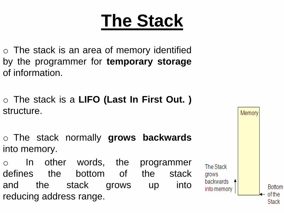
o The stack is an area of memory identified
by the programmer for temporary storage
of information.
o The stack is a LIFO (Last In First Out. )
structure.
o The stack normally grows backwards
into memory.
o In other words, the programmer
defines the bottom of the stack
and the stack grows up into
reducing address range.
The Stack

o Given that the stack grows backwards into memory, it
is customary to place the bottom of the stack at the end
of memory to keep it as far away from user programs
as possible.
o In the 8085, the stack is defined by setting the SP
(Stack Pointer) register.
LXI SP, FFFFH
o This sets the Stack Pointer to location FFFFH (end of
memory for the 8085).
The Stack
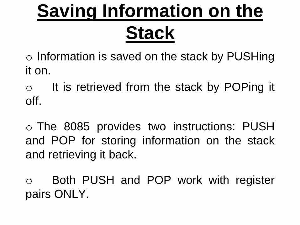
o Information is saved on the stack by PUSHing
it on.
o It is retrieved from the stack by POPing it
off.
o The 8085 provides two instructions: PUSH
and POP for storing information on the stack
and retrieving it back.
o Both PUSH and POP work with register
pairs ONLY.
Saving Information on the
Stack

The PUSH Instruction
● PUSH B/D/H/PSWo Decrement SP
o Copy the contents of register B to the memory location
pointed to by SP
o Decrement SP
o Copy the contents of register C to the memory location
pointed to by SP

The POP Instruction● POP B/D/H/PSWo Copy the contents of the memory location pointed to by the
SP to register E
o Increment SP
o Copy the contents of the memory location pointed to by the
SP to register D
o Increment SP

o During pushing, the stack operates in a “decrement
then store” style.
o The stack pointer is decremented first, then the
information is placed on the stack.
o During poping, the stack operates in a “use then
increment” style.
o The information is retrieved from the top of the the
stack and then the pointer is incremented.
o The SP pointer always points to “the top of the stack”.
Operation of the Stack
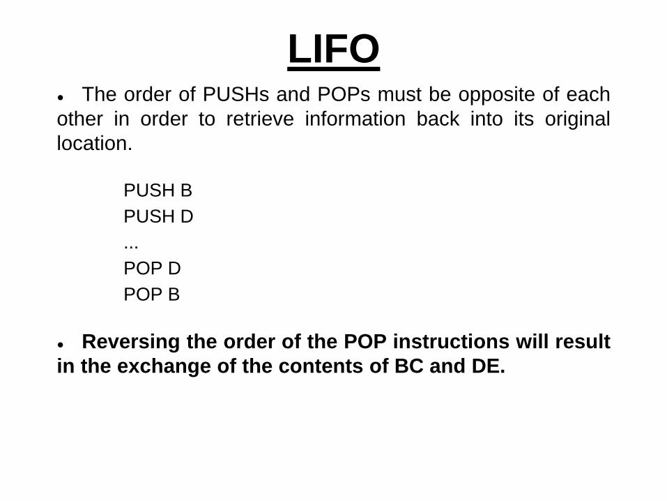
● The order of PUSHs and POPs must be opposite of each
other in order to retrieve information back into its original
location.
PUSH B
PUSH D
...
POP D
POP B
● Reversing the order of the POP instructions will result
in the exchange of the contents of BC and DE.
LIFO

The PSW Register Pairo The 8085 recognizes one additional register pair
called the PSW (Program Status Word).
o This register pair is made up of the Accumulator
and the Flags registers.
o It is possible to push the PSW onto the stack, do
whatever operations are needed, then POP it off of the
stack.
o The result is that the contents of the Accumulator
and the status of the Flags are returned to what they
were before the operations were executed.

Cautions with PUSH and
POP● PUSH and POP should be used in opposite
order.
● There has to be as many POP’s as there are
PUSH’s.
● If not, the RET statement will pick up the
wrong information from the top of the stack and
the program will fail.
● It is not advisable to place PUSH or POP
inside a loop.

Program to Reset and display
FlagsoClear all Flags.
oLoad 00H in the accumulator, and
demonstrate that the zero flag is not affected
by data transfer instruction.
oLogically OR the accumulator with itself to
set the Zero flag, and display the flag at
PORT1 or store all flags on the stack.

Program to Reset and display
Flags●XX00 LXI SP, XX99H Initialize the stack
●03 MVI L, 00H Clear L
●05 PUSH H Place (L) on stack
●06 POP PSW Clear Flags
●07 MVI A, 00H Load 00H
●09 PUSH PSW Save Flags on stack
●0A POP H Retrieve flags in L
●0B MOV A, L
●0C OUT PORT0 Display Flags (00H)
●0E MVI A, 00H Load 00H Again

Program to Reset and display
Flags●XX10 ORA A Set Flags and reset
CY, AC
●11 PUSH PSW Save Flags on Stack
●12 POP H Retrieve Flags in L
●13 MOV A, L
●14 ANI 40H Mask all Flags except Z
●16 OUT PORT1 Displays 40H
●18 HLT End of Program

o A subroutine is a group of instructions that will be
used repeatedly in different locations of the program.
o Rather than repeat the same instructions several
times, they can be grouped into a subroutine that is
called from the different locations.
o In Assembly language, a subroutine can exist
anywhere in the code.
o However, it is customary to place subroutines
separately from the main program.
Subroutines

o The 8085 has two instructions for dealing with
subroutines.
o The CALL instruction is used to redirect
program execution to the subroutine.
o The RTE instruction is used to return the
execution to the calling routine.
Subroutines

The CALL Instruction● CALL 4000H
o 3-byte instruction.
o Push the address of the instruction immediately following the
CALL onto the stack and decrement the stack pointer register by
two.
o Load the program counter with the 16-bit address supplied
with the CALL instruction.
o Jump Unconditionally to memory location.

The CALL Instruction
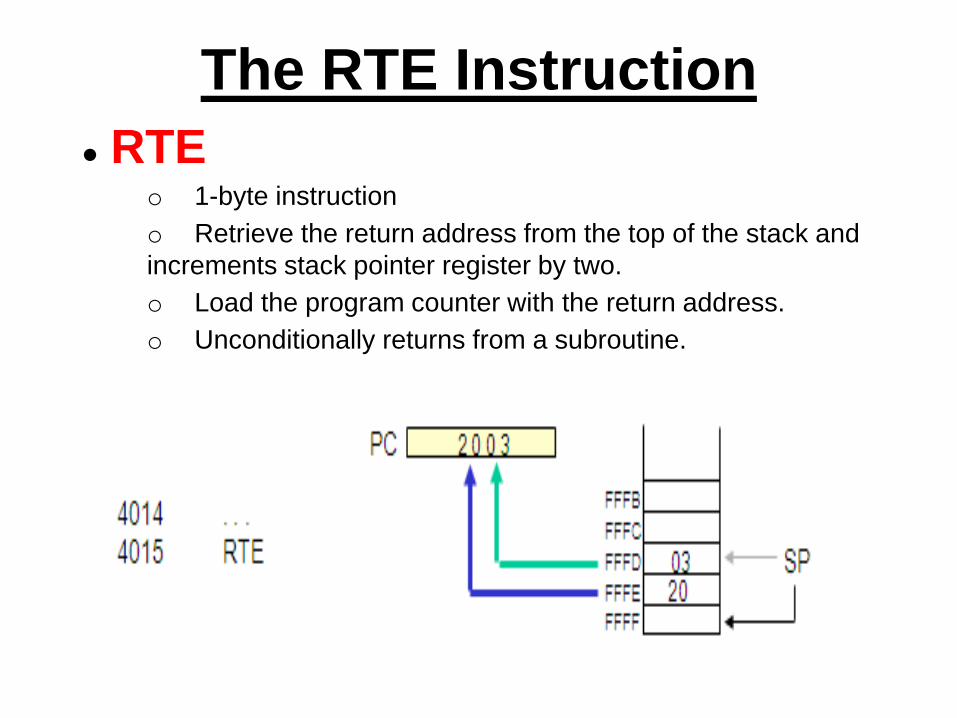
● RTEo 1-byte instruction
o Retrieve the return address from the top of the stack and
increments stack pointer register by two.
o Load the program counter with the return address.
o Unconditionally returns from a subroutine.
The RTE Instruction

Illustrates the exchange of information between stack
and Program Counter
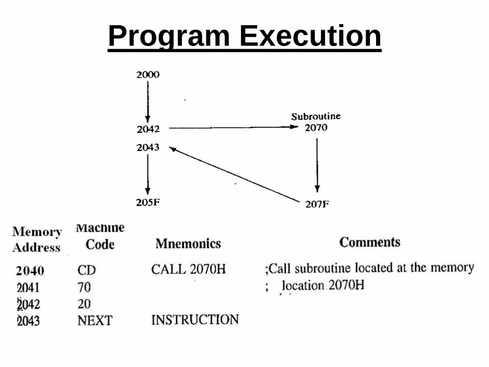
Program Execution

CALL Execution● Instruction requires five machine cycles and eighteen T-
states: Call instruction is fetched, 16-bit address is read during M2 and M3 and
stored temporarily in W/Z registers. In next two cycles content of program counter are
stored on the stack (address from where microprocessor continue it execution of
program after completion of the subroutine.)

RET Execution● Program execution sequence is transferred to the memory location 2043H
location.M1 is normal fetch cycle during M2 contents of stack pointer are placed on
address bus so 43H data is fetched and stored on Z register and SP is upgraded.
Similarly for M3. Program sequence is transfered to2043H by placing contents of
W/Z on address bus.
Passing Data to a
Subroutineo In Assembly Language data is passed to a
subroutine through registers.
o The data is stored in one of the registers by the
calling program and the subroutine uses the value from
the register.
o The other possibility is to use agreed upon memory
locations.
o The calling program stores the data in the memory
location and the subroutine retrieves the data from the
location and uses it.
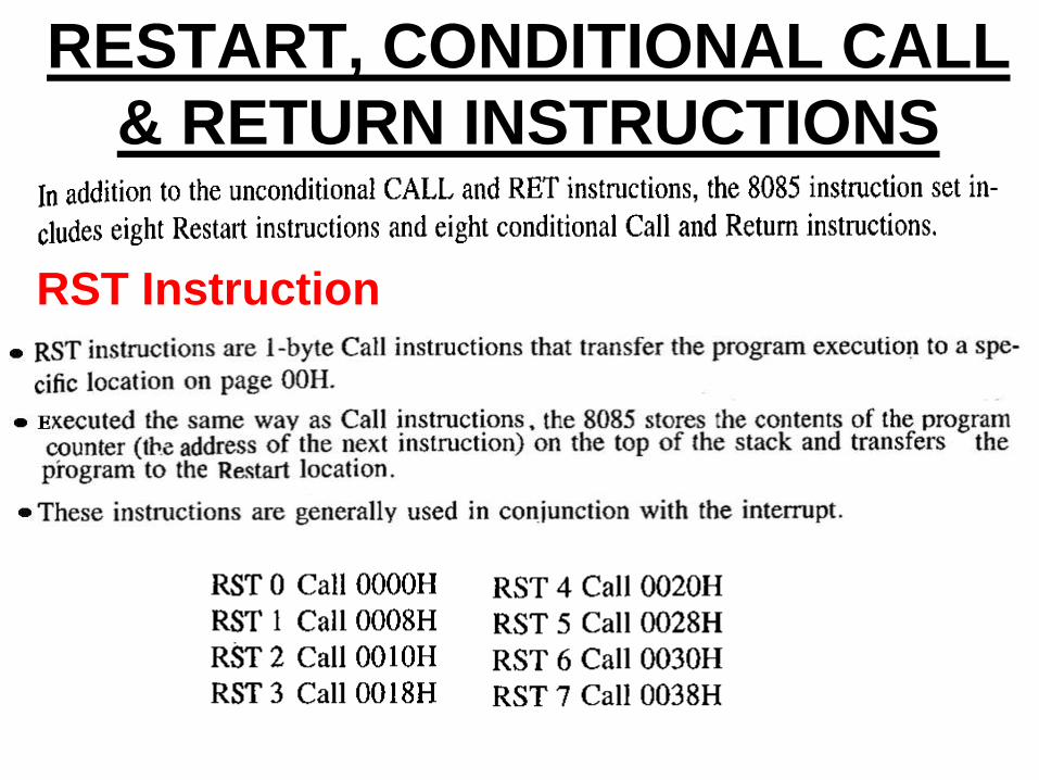
RESTART, CONDITIONAL CALL
& RETURN INSTRUCTIONS
RST Instruction

RESTART, CONDITIONAL CALL
& RETURN INSTRUCTIONS
Conditional CALL

RESTART, CONDITIONAL CALL
& RETURN INSTRUCTIONS
Conditional RETURN

A Proper Subroutine
o According to Software Engineering practices, a
proper subroutine:
o Is only entered with a CALL and exited with an
RTE
o Has a single entry point
o Do not use a CALL statement to jump into
different points of the same subroutine.

Writing SubroutinesWrite a Program that will display FF and 11 repeatedly on the
seven segment display. Write a ‘delay’ subroutine and Call it as
necessary.
C000: LXI SP, FFFF
C003: MVI A, FF
C005: OUT 00
C007: CALL C014
C00A: MVI A, 11
C00C: OUT 00
C00E: CALL 1420
C011: JMP C003

Writing Subroutines
DELAY: C014: MVIB, FF
C016: MVIC, FF
C018: DCR C
C019: JNZ C018
C01C: DCR B
C01D: JNZ C016
C020: RET

Nesting Subroutines

Problem Statement

Problem Statement

Problem Statement

Problem Statement

Problem Statement