
Stacked-origami mechanical metamaterial with tailored ...
29
Stacked-origami mechanical metamaterial with tailored multistage stiffness Guilin Wen Yanshan University Gaoxi Chen Guangzhou University Kai Long North China Electric Power University Xuan Wang Hefei University of Technology Jie Liu ( [email protected] ) Guangzhou University Yi Min Xie RMIT University Research Article Keywords: Zigzag-base stacked-origami metamaterial, tailored stiffness, tailored microstructures, compression molding, quasi-static compression experiment Posted Date: August 27th, 2021 DOI: https://doi.org/10.21203/rs.3.rs-849340/v1 License: This work is licensed under a Creative Commons Attribution 4.0 International License. Read Full License Version of Record: A version of this preprint was published at Materials & Design on December 1st, 2021. See the published version at https://doi.org/10.1016/j.matdes.2021.110203.
Transcript of Stacked-origami mechanical metamaterial with tailored ...

Stacked-origami mechanical metamaterial withtailored multistage stiffnessGuilin Wen
Yanshan UniversityGaoxi Chen
Guangzhou UniversityKai Long
North China Electric Power UniversityXuan Wang
Hefei University of TechnologyJie Liu ( [email protected] )
Guangzhou UniversityYi Min Xie
RMIT University
Research Article
Keywords: Zigzag-base stacked-origami metamaterial, tailored stiffness, tailored microstructures,compression molding, quasi-static compression experiment
Posted Date: August 27th, 2021
DOI: https://doi.org/10.21203/rs.3.rs-849340/v1
License: This work is licensed under a Creative Commons Attribution 4.0 International License. Read Full License
Version of Record: A version of this preprint was published at Materials & Design on December 1st, 2021.See the published version at https://doi.org/10.1016/j.matdes.2021.110203.

Stacked-origami mechanical metamaterial with tailored multistage stiffness
Guilin Wen1,2, Gaoxi Chen2, Kai Long3, Xuan Wang4, Jie Liu2*, Yi Min Xie5
1School of Mechanical Engineering, Yanshan University, Hebei 066004, China2Center for Research on Leading Technology of Special Equipment, School of Mechanical and
Electric Engineering, Guangzhou University, Guangzhou 510006, China3State Key Laboratory for Alternate Electrical Power System with Renewable Energy Sources,
North China Electric Power University, Beijing, 102206, China4Department of Engineering Mechanics, Anhui Key Laboratory of Civil Engineering Structures
and Materials, Hefei University of Technology, Hefei 230009, China5Centre for Innovative Structures and Materials, School of Engineering,
RMIT University, Melbourne 3001, Australia
*Correspondence and requests for materials should be addressed toJ.L. (email: [email protected])
Abstract:
Origami-baed metamaterial has shown remarkable mechanical properties rarely found in natural
materials, but achieving tailored multistage stiffness is still a challenge. This study proposes a
novel zigzag-base stacked-origami (ZBSO) metamaterial with tailored multistage stiffness
property based on crease customization and stacking strategies. A high precision finite element
(FE) model to identify the stiffness characteristics of the ZBSO metamaterial has been established,
and its accuracy is validated by quasi-static compression experiments. Using the verified FE
model, we demonstrate that the multistage stiffness of the ZBSO metamaterial can be effectively
tailored through two manners, i.e. varying the microstructures (through introducing new creases to
the classical Miura origami unit cell) and altering the stacking way. Three strategies are utilized to
vary the microstructure, i.e. adding new creases to the right, left, or both sides of the unit cell. We
further reveal that the proposed ZBSO metamaterial has several outstanding advantages compared
with traditional mechanical metamaterials, e.g. material independent, scale-invariant, lightweight,
and excellent energy absorption capacity. The unravelled superior mechanical properties of the
ZBSO metamaterials pave the way for the design of the next-generation cellular metamaterials
with tailored stiffness properties.
Keywords: Zigzag-base stacked-origami metamaterial; tailored stiffness; tailored microstructures;
compression molding; quasi-static compression experiment.
1. Introduction
Mechanical metamaterials are unique structures whose properties are determined not by their
material composition as conventional structures but by the geometric configuration of the
microstructure units [1-3]. Due to its unconventional mechanical properties, for instance, negative
Poisson's ratio, negative effective mass, negative modulus, chirality, et al., it has broad application
prospects [4-8]. The empirical method is the mainstream method of designing such mechanical
metamaterials. Although this method has demonstrated powerful capabilities, it is difficult to
exploit the superior properties fully. As a remedy, topology optimization methods have been
further developed to design mechanical metamaterials with optimal (or locally optimal)
mechanical properties [9-11]. Nevertheless, topology optimization may not always be possible
obtaining the desired optimal solutions, thereby leading to the imperious demand for new design
ideas for the mechanical metamaterial.
The origami technique may be one answer to the above question. Due to its simple concept,
fascinating characteristic, and wide application prospects, origami has aroused great interest of
mathematicians, scientists and engineers in recent year [12], leading to a series of innovative
designs [13-35], for instance, foldable lithium-ion battery, origami robot, foldscope, bioinspired
spring, active structures, energy absorbing-structures/materials sandwich panels. Furthermore, the
recent inspiration for the design of mechanical metamaterials has made it even more compelling;
especially recent studies reveal that origami-based mechanical metamaterials have unique
properties that traditional mechanical materials do not have. Mechanical metamaterials based on
Miura origami are the most widely studied among them. Miura origami itself is a mechanical
metamaterial with two distinct Poisson’s ratio properties, i.e. a negative one for in-plane
deformations and a positive one for out-of-plane bending, which is dominated by the kinematics
of the folding [36]. Through expanding on the design space of Miura origami, its variants can
achieve adjusting Poisson's ratio between positive and negative [37]. Tunable negative Poisson’s
ratio can be realized by the cylindrical derivative of Miura origami, e.g. the Tachi Miura
polyhedron [38]. Stiffness represents the ability to resist deformation, which is another key
performance index of mechanical metamaterials. The operating environment of engineering
equipment is generally complex and changeable, resulting in structures with different stiffness

characteristics for various load conditions that are significantly desired. Thus, the tailored stiffness
characteristics of the mechanical metamaterial are essential for the engineering equipment, which
is an uneasy task for traditional design methods. Cylindrical origami-inspired mechanical
metamaterials were designed and analyzed via energy landscapes and strain variations; by
controlling the stiffness, the required deployability and collapsibility can be realized [39]. By
considering the mixed mode of deformations involving both rigid origami motion and facet
bending, the deformation stiffness of mechanical metamaterials with the waterbomb bases can be
tailored, forming a potential long-distance actuation mechanism with a single far-field force [40].
To further expand the design freedom of Miura origami, mechanical metamaterials based on
curved crease origami can accomplish in situ stiffness manipulation by alteration of the curvature
of the creases [41]. Although these studies have successfully achieved tailored stiffness
characteristics, there is still room for further expansion of its design freedom.
Stacking origami mechanical metamaterials to structure novel mechanical metamaterials (SOMM)
can gain more fruitful tailored stiffness characteristics due to introducing extra design freedoms,
e.g. stacking order and sacking way [42]. For instance, the high-static-low-dynamic stiffness
property can be harnessed by SOMM, which is extremely important in the field of low-frequency
vibration isolation [43-46]. Our previous work revealed that stacking two Miura sheets to form a
SOMM can achieve the realization of tailoring the dynamic stiffness [47]. By non-uniformly
stacking Miura sheets, Chen and coworkers have designed a series of novel mechanical
metamaterials, whose graded stiffness characteristics were investigated by combining kinematic
analysis, numerical simulation and experimental method [48,49]. Interestingly, Li and coworkers
combined the stacked Miura origami and rhombic honeycomb structure to develop new
mechanical metamaterials with a two-stage programmable compressive strength [50]. The concept
of this combination of different configurations to gain incredible performances has received
considerable attention in many fields [51]. Alternatively, introducing additional microstructures to
the mechanical metamaterial is another promising way to significantly improve the performance
[52,53]. Nevertheless, studies on SOMM based on this idea are limited. In this study, we will
show how to use the stacking and introducing additional microstructures strategies to tailor the
stiffness of the mechanical metamaterial. The microstructures can be readily introduced by adding

extra creases [54]. To this end, we have proposed a novel zigzag-base stacked-origami (ZBSO)
metamaterial based on the unique geometric construction and architecture. By adding new creases
to the classical Miura sheet to introduce microstructures, the proposed ZBSO metamaterial can
manifest beneficial tailored stiffness properties, systematically investigated by numerical and
experimental methods.
2. Materials and methods
2.1. Geometric design
This section shows the geometric design for the ZBSO metamaterial based on strict mathematical
geometric relationships. ZBSO metamaterial consists of N_layer stacks in the z-direction, and
each stack includes two basic zigzag-base sheets. The unit cell for constructing the zigzag-base
sheet is the derivation of the Miura origami (DMO) unit cell with additional creases, as shown in
FIG.1A. Miura origami is made of four parallelogram. We further introduce microstructures to the
facet, i.e. equally divide the parallelogram into n small ones, e.g. dividing into three small
identical parallelograms, whose 2D crease pattern is depicted in the left panel of FIG.1A. Since we
assume the DMO unit cell is rigid-foldable, only four parameters are needed to determine the
geometry of the unit cell in space, i.e. the length, a, the width, b, and the acute angle, ϕ, for the
parallelogram, and the folding angle, θ. The following geometric relationships should be carefully
followed if one intends to obtain the 3D geometry as shown in the right of FIG.1A.
2 2 2
2 2 2
cos / 2 coscos
sin /si
2 cosn
cos
(1A)
2 2cos sin cos cos (1B)
2 sin / 2w b (1C)
cos / 2h a (1D)
2 sin / 2l a (1E)
cos / 2v b (1F)
We then repeat the DMO unit cell in the x-direction and y-direction, resulting in nx and ny unit
cells in the x-direction and y-direction, respectively. For example, FIG.1B shows the case when

nx=3 and ny=1. We name this structure as the derivation of Miura origami sheet (DMOS) in
subsequent sections to facilitate description. By assembling the upper-DMOS and the
lower-DMOS at their open sides, one can obtain a stack for forming the ZBSO metamaterial. The
upper-DMOS and the lower-DMOS can be identical or different but should be amenable to strict
mathematical relationships, as follows,1
2
12 cos
cosnlnl nl
nl
aa
(2A)
12nl nlb b (2B)
22
121212
sinsin2sin1cosnl
nlnlnl
(2C)
where ( 1nla , 1
nlb , 1nl , 1
nl ) and ( 2nla , 2
nlb , 2nl , 2
nl ) are the parameters for dominating the geometric
topology of lower-DMOS and upper-DMOS, respectively. A specific case, i.e. the first layer with
nl equals to 1, is depicted in FIG.1C.
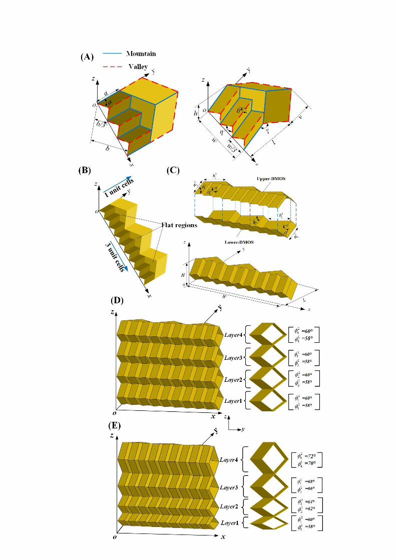

FIG 1 Geometric design for the ZBSO metamaterial: (A) The unit cell; (B) DMOS with 3 and 1units in x-direction and y-direction, respectively; (C) One stack (DMOS tube) for constructing ZBSOmetamaterial; (D) and (E) Two Different ZBSO metamaterials by varying the acute angle ϕ. Left:
Stereogram perspective; right: lateral view.
By duplicating the stack presented in FIG.1C in the z-direction, one finally obtains the ZBSO
mechanical metamaterial with nl layers (nl is also the number of cells presented in FIG.1C).
Notice that each layer is connected through the flat regions of the upper-DMOS and the
lower-DMOS, forming a DMOS tube. From Equations (2A)-(2C), it can be easily found that
varying the acute angle, ϕ, of the DMOS in each stack will yield diverse ZBSO metamaterials. For
ease of description, we utilize a pair of ϕ to represent the DMOS tube, in which the first value
refers to lower-DMOS and the second value the upper-DMOS. For instance, FIGs 1D-E depict
two representative cases, as [(60°,60°), (60°,60°), (60°,60°), (60°,60°)] and [(58°,60°), (62°,64°),
(66°,68°), (70°,72°)], respectively.
It should be noted that we first identify the four geometric parameters for the lower-DMOS of the
first layer, i.e. the length, 11a , the width, 1
1b , and the acute angle, ϕ11, for the parallelogram, and
the folding angle, 11 , and the other geometric parameters of DMOS for constructing ZBSO
metamaterial can be analytically calculated by using Equations (1A)-(1F) and Equations
(2A)-(2C).
2.2. Tensile tests
Brass (H62) is utilized for constituting ZBSO metamaterial mainly considering its good ductility.
To obtain the mechanical property of the brass, we use a machine CMT5105 (Type: SUST) with
an electronic extensometer (Type: YYU-12.5/25) to conduct the tensile tests, finding that the brass
with a thickness of 0.2 mm can be characterized by the parameters summarized in Table 1. These
parameters will be utilized in the succeeding finite element (FE) simulations.
Table 1 Parameters for characterizing the mechanical property of the brass
Young’s modulus Yield stress Tensile strength Elongation Poisson’s ratio Density
103.6 GPa 363.0 MPa 622.5 MPa 18.8% 0.33 8.9 g·cm-3
2.3 FE modelling

To capture the tailored stiffness property of ZBSO metamaterial, numerical simulations are
performed utilizing nonlinear finite element code Abaqus/Explicit. Four-node shell elements (S4)
are employed to mesh the ZBSO metamaterial. Global element size is chosen as 1.2 mm,
determined by the mesh sensitivity analysis as shown in subsection 3.1. ZBSO is rest on a rigid
plate during the simulation. A rigid plate is initially on the top edge of ZBSO. All the nodes of the
flat regions on the upper-DMOS of the top unit cell are coupled to a coupling point on the rigid
plate, and the displacement of the coupling point is controlled to simulate the quasi-static
compression process. Two contact properties are set in the simulation, i.e. penalty friction with the
Coulomb friction coefficient as 0.3 and hard contact model to character the contact pressure
between surfaces. Brass (H62) is used as the constituted material to construct ZBSO, whose
mechanical properties are obtained from the tensile tests provided in subsection 2.2. FIG 2A
shows the FE model's axonometric view and lateral view for the ZBSO metamaterial with four
layers, respectively. The geometric parameters to determine the topology of the ZBSO
metamaterial are presented in Table 2.


FIG 2 FE modelling verification for the ZBSO metamaterial: (A) FE modelling (Left:Axonometric view and right: lateral view); (B) Fabrication process (Left: moulds for creating theDMOS and right: a representative manufacturing process); (C) Experimental setup for testing the
tailored stiffness property of the ZBSO metamaterial.
Table 2 Design parameters of FE model for the ZBSO metamaterial.
21 , nlnl (°) 21 , nlnl aa (mm) 21 , nlnl bb (mm) 21 , nlnl (°) nl
58, 60 18.87, 20 24 135.49, 130.00 158, 60 18.87, 20 24 135.49, 130.00 258, 60 18.87, 20 24 135.49, 130.00 358, 60 18.87, 20 24 135.49, 130.00 4
It should be noted that, to ensure the accuracy of the simulations, the following two situations
should be carefully considered [26]:
(1) The ratio of artificial energy to internal energy is below 5% to make sure that the
hour-glassing effect would not significantly affect the results;
(2) The ratio of kinetic energy to internal energy is below 5% during most crushing
processes to ensure that dynamic effects can be considered insignificant.
2.3. Fabrication of ZBSO
There are many manufacturing methods for making origami structure prototypes, e.g.
manual-folding, cold grass-pressure folding process, compression molding, bending and welding,
self-folding [22,47,56-58]. Here, we adopt a five-step fabrication strategy based on the
compression molding method to make the real ZESO metamaterial samples, as shown in FIG 2B.
To ensure the accuracy of the sample, two pairs of male and female moulds for fabricating DMOS
are processed by a vertical machining center (Type: HS-1066H), and the material used is 45 steel;
the surface of the mold is further plated with a layer of chromium metal to increase the hardness
and wear resistance of the mold. A hydraulic stamping press (type: LY-WDQ20A4) is employed to
conduct the compression moulding of DMOS. A commercial glue ergo 1690 is used to form the
ZESO metamaterial samples.
2.4. Experimental setup
The identical tensile machine used in subsection 2.1 is employed to experimentally investigate the
quasi-static compression process and to further reveal the tailored stiffness property of the ZBSO

metamaterial, as shown in FIG 3C. The ZBSO metamaterial sample is placed between the loading
plant and the fixed plant. The lower end of the ZBSO metamaterial sample is fixed, and the upper
end moves slowly down with the loading plant until the whole sample collapses. The data for the
quasi-static compression process, i.e. the displacement and the load, is gathered by a data collector
and then processed by a personal computer, finally obtaining the relationship between the
displacement and the force.
3. Results and discussion
3.1 Mesh sensitivity analysis
Mesh sensitivity analysis is performed to determine the mesh size to weigh the simulation
accuracy against efficiency. We test five different mesh sizes, i.e.
0.8mm×0.8mm,1.0mm×1.0mm,1.2mm×1.2mm, 1.4mm×1.4mm, and 1.6mm×1.6mm, determining
that mesh size with 1.2mm×1.2mm has relatively high accuracy and good efficiency (see FIG 3A).
Thus, the mesh size will be employed in the FE models through all the simulations in this work.
FIG 3 Comparative results between FE simulation and experimental study for the ZBSOmetamaterial: (A) Mesh sensitivity analysis; (B) force VS displacement curve for Test 1 and (C)
Test 2; (D) Deformation process corresponding to Test 1 and (E) Test 2.
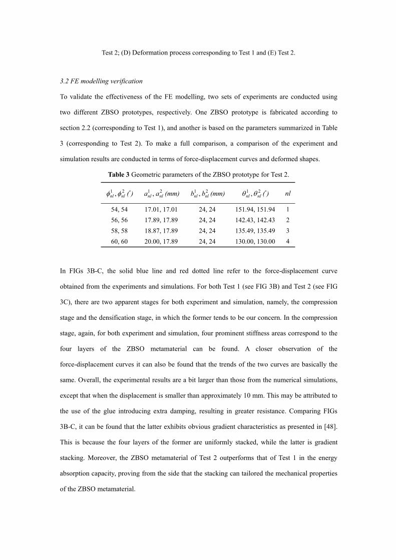
3.2 FE modelling verification
To validate the effectiveness of the FE modelling, two sets of experiments are conducted using
two different ZBSO prototypes, respectively. One ZBSO prototype is fabricated according to
section 2.2 (corresponding to Test 1), and another is based on the parameters summarized in Table
3 (corresponding to Test 2). To make a full comparison, a comparison of the experiment and
simulation results are conducted in terms of force-displacement curves and deformed shapes.
Table 3 Geometric parameters of the ZBSO prototype for Test 2.
21 , nlnl (°) 21 , nlnl aa (mm) 21 , nlnl bb (mm) 21 , nlnl (°) nl
54, 54 17.01, 17.01 24, 24 151.94, 151.94 156, 56 17.89, 17.89 24, 24 142.43, 142.43 258, 58 18.87, 17.89 24, 24 135.49, 135.49 360, 60 20.00, 17.89 24, 24 130.00, 130.00 4
In FIGs 3B-C, the solid blue line and red dotted line refer to the force-displacement curve
obtained from the experiments and simulations. For both Test 1 (see FIG 3B) and Test 2 (see FIG
3C), there are two apparent stages for both experiment and simulation, namely, the compression
stage and the densification stage, in which the former tends to be our concern. In the compression
stage, again, for both experiment and simulation, four prominent stiffness areas correspond to the
four layers of the ZBSO metamaterial can be found. A closer observation of the
force-displacement curves it can also be found that the trends of the two curves are basically the
same. Overall, the experimental results are a bit larger than those from the numerical simulations,
except that when the displacement is smaller than approximately 10 mm. This may be attributed to
the use of the glue introducing extra damping, resulting in greater resistance. Comparing FIGs
3B-C, it can be found that the latter exhibits obvious gradient characteristics as presented in [48].
This is because the four layers of the former are uniformly stacked, while the latter is gradient
stacking. Moreover, the ZBSO metamaterial of Test 2 outperforms that of Test 1 in the energy
absorption capacity, proving from the side that the stacking can tailored the mechanical properties
of the ZBSO metamaterial.

To further verify the accuracy of the FE model, close-up views during the deformation process for
the simulations and experiments are grabbed, which are shown in FIGs 3D-E, respectively. Eight
typical close-up views are selected according to the axial compressive strain, ɛ, of the ZBSO
metamaterial, i.e. ɛ is equal to 0, 0.17, 0.33, 0.38, 0.47, 0.53, 0.61 and 0.70 for Test 1 and 0, 0.09,
0.13, 0.23, 0.34, 0.40, 0.57 and 0.74 for Test 2. ɛ equals to 0 represents the initial state, and as ɛ
increases, the ZBSO metamaterial is gradually compressed. For all close-up views, the simulation
and experiment deformations are in excellent agreement. In short, the effectiveness of the FE
modelling for the ZBSO metamaterials has been well verified. The validated FE model will be
employed to comprehensively investigate the tailored stiffness property of the ZBSO
metamaterial.
3.3 The tailored multistage stiffness characteristic of the ZBSO metamaterial
In this section, we will show how the stiffness of the ZBSO metamaterial can be tailored by
varying the microstructures (three strategies to add new creases) and altering the stacked way by
utilizing the validated FE model.
3.3.1 Varying the microstructures
We introduce three strategies to add new creases to the ZBSO metamaterial and investigate how
they tailor the stiffness. The related geometric parameters are identical to that used in the FE
modelling of Test 1, as shown in Table 2. FIG 4 shows how the multistage stiffness of the ZBSO
metamaterial is tailored through adding new creases to the right sides of the unit cell, where five
cases are investigated, i.e. n=1:1, n=1:2, n=1:3, n=1:4, and n=1:5. As stated in section 2.1, n
represents the number of microstructures introduced, e.g. n=1:5 means the right sides of the unit
cell is evenly divided into five small microstructures with the left sides unchanged. At the top of
FIG 4, the geometry of the unit cells for the five cases after introducing microstructures are
presented. The snapshots of the deformation shapes of the three representative moments, i.e. the
displacements (abbreviated as disp in the succeeding figures) are 15mm, 31mm, and 44mm,
respectively, for the five ZBSO metamaterials are also given for ease of description. When n=1:1,
the ZBSO metamaterial is constructed by traditional Miura unit cells, which is geometrically
similar to [48]. Look close to the force-displacement curve, it first slowly increases from zero,

then enters the platform area, and finally densification occurs, which is also consistent with that
observed in [48]. It can be found that, in this case, multistage stiffness is not realized since
identical DMOS tubes for four stacks are used and no additional microstructures are introduced.
Now we keep the DMOS tubes identical but introduce new creases, e.g. n=1:2, n=1:3, n=1:4, and
n=1:5. It can be found that multistage stiffness characteristics can be clearly observed. Moreover,
the number of the creases introduced significantly influences the multistage stiffness characteristic.
Roughly speaking, as decrease the value of n (with more microstructures), the multistage stiffness
characteristic becomes increasingly apparent. Specifically, for the ZBSO metamaterial with n=1:2,
the first trough appears when the displacement is about 27mm, which lags other cases, e.g. it is
roundly 15mm for the ZBSO metamaterial with n=1:3. It can also be found that the more creases
are introduced, the earlier the first trough will emerge, and the more obvious the multi-level
stiffness characteristic will be. To further demonstrate the phenomena mentioned above, several
snapshots are extracted from the deformation shapes of the ZBSO metamaterials of the
representative moments, i.e. the displacement equals 15mm and 27mm. When disp=15mm, the
ZBSO metamaterials with n=1:1 and n=1:2 are in the platform area, and the deformation is mainly
contributed by the rotation of the creases (served as plastic hinges); when n=1:3, the first layer of
the ZBSO metamaterial happens to be self-locking with the emergence of the first trough of the
force-displacement curve [48]; for the cases n=1:4 and n=1:5, the first layer of the ZBSO
metamaterial has been self-locked and the facets begin to deform, leading to the deformation of
the ZBSO metamaterial is dominated by both the rotation of the creases and the bending of the
facets. Let's turn our eyes back to the case when disp=27mm, the deformation of the ZBSO
metamaterial with n=1:1 is also caused by the rotation of the creases; while the ZBSO
metamaterial with n=1:2 just enters the self-locking state for its first layer; for the ZBSO
metamaterials with more microstructures, for instance, the ZBSO metamaterials with n=1:3 and
n=1:4 undergo deformations contributed by layer 1 and layer 4, and layer 4 has not appeared
self-locking; however, when n=1:5, self-locking has occurred in two layers of the ZBSO
metamaterial, i.e. layer 1 and layer 2, which deformation mode is different from the previous two.
Therefore, it can be found that simply adding microstructures can significantly tailor the
multistage stiffness of the ZBSO metamaterial.
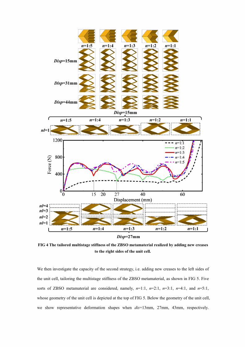
FIG 4 The tailored multistage stiffness of the ZBSO metamaterial realized by adding new creasesto the right sides of the unit cell.
We then investigate the capacity of the second strategy, i.e. adding new creases to the left sides of
the unit cell, tailoring the multistage stiffness of the ZBSO metamaterial, as shown in FIG 5. Five
sorts of ZBSO metamaterial are considered, namely, n=1:1, n=2:1, n=3:1, n=4:1, and n=5:1,
whose geometry of the unit cell is depicted at the top of FIG 5. Below the geometry of the unit cell,
we show representative deformation shapes when dis=13mm, 27mm, 43mm, respectively.

Through the force-displacement curve, it can be apparently detected that the multistage stiffness
characteristic can be only carried out for ZBSO metamaterials with n=3:1, n=4:1, and n=5:1,
which is slightly different from those in the first strategy. Thus, comparing FIG 4 and FIG 5, we
can find a simple way to tailor the stiffness of the ZBSO metamaterial by altering the position of
the introduced additional creases. When the axial deformation is 13mm, layer 1 of the ZBSO
metamaterials with n=3:1, n=4:1, and n=5:1 reach the self-locking point almost simultaneously.
Nevertheless, when disp=27mm, the ZBSO metamaterials with n=3:1 and n=4:1 enter the
self-locking state and the ZBSO metamaterial with n=5:1 lags slightly. At the moment, the
deformation of the ZBSO metamaterials is caused by both the rotation of the creases and bending
of the facets of layer 1 and layer 4. Moreover, it can be found that the side where the
microstructure is not introduced is more prone to self-locking, which is consistent with the
phenomenon observed in FIG 4.
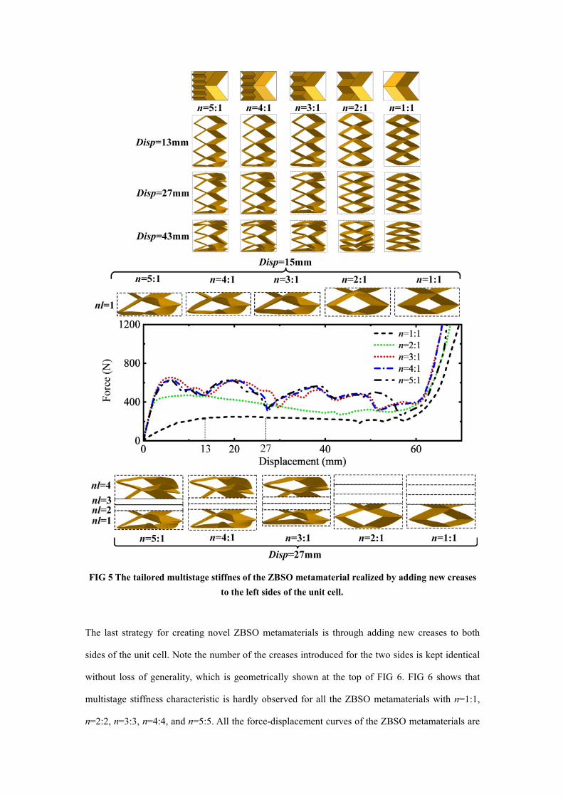
FIG 5 The tailored multistage stiffnes of the ZBSO metamaterial realized by adding new creasesto the left sides of the unit cell.
The last strategy for creating novel ZBSO metamaterials is through adding new creases to both
sides of the unit cell. Note the number of the creases introduced for the two sides is kept identical
without loss of generality, which is geometrically shown at the top of FIG 6. FIG 6 shows that
multistage stiffness characteristic is hardly observed for all the ZBSO metamaterials with n=1:1,
n=2:2, n=3:3, n=4:4, and n=5:5. All the force-displacement curves of the ZBSO metamaterials are

similar to that of when n=1:1 such that as the microstructure increases, the curves generally move
up as a whole, except for some small fluctuations for n=3:3, n=4:4, and n=5:5. When disp=28mm,
the deformation of layer 1 is dominated by the rotation of the creases for all the five kinds of
ZBSO metamaterials. When the displacement increases to 40mm, it can be found that the
deformation is almost evenly contributed by the rotation of the creases of four layers for ZBSO
metamaterials with n=1:1 and n=2:2; while for the ZBSO metamaterials with n=4:4 and n=5:5, the
deformation is mainly provided by layer 1 and layer 2, in which the former one is dominated by
the rotation of the creases and the latter one by both the rotation of the creases and the bending of
the facets; the notable difference is found for the ZBSO metamaterial with n=3:3 that the
deformation of layer 2 mainly contributes the whole deformation. Hence, simply changing the
number of additional creases can tailor the deformation mode and the multistage stiffness of the
ZBSO metamaterial.
Comprehensively analyzing all the three strategies, it is interesting to find that when fewer creases
are introduced, each layer of the ZBSO metamaterial will be compressed before the self-locking of
the first layer occurs, i.e. simultaneous deformation of the four layers is more obvious. In
comparison, sequence deformation of each layer of the ZBSO metamaterial is clearly observed
when more creases are added. Besides, from the perspective of energy absorption, the ZBSO
metamaterial with more microstructures introduced, the better the energy absorption performance
will be. The peak force obtained by the first two strategies is not much different and larger than
that of the third strategy. Analyzing the peak force and the area contained in the force and
displacement curve before the densification area, the ZBSO metamaterials obtained by these three
strategies all have good application potential in the field of energy absorption.

FIG 6 The tailored multistage stiffnes of the ZBSO metamaterial realized by adding new creasesto the both sides of the unit cell.
3.3.2 Altering the stacked order
FIG 7 shows how the stiffness of the ZBSO metamaterial can be tailored through altering the
stacked order of different DMOS tubes with n=1:3. Four sorts of DMOS tubes are chosen, i.e.
(58°,60°), (62°,64°), (66°,68°), and (70°,72°). The related geometric parameters are shown in Table 4.
Adjusting the stacked order of these DMOS tubes leads to various ZBSO metamaterials; strictly

speaking, there are 24 kinds. Here we carefully select four ZBSO metamaterials without loss of
generality, i.e. (58°,60°)-(62°,64°),-(66°,68°)-(70°,72°), (58°,60°)-(70°,72°)-(66°,68°)-(62°,64°),
(66°,68°)-(62°,64°)-(58°,60°)-(70°,72°), and (62°,64°)-(70°,72°)-(58°,60°)-(66°,68°). FIG 7 reveals that
the multistage stiffness of the ZBSO metamaterial can be effectively tailored by simply changing
the stacking sequence of the DMOS tubes, particularly for the one
(66°,68°)-(62°,64°)-(58°,60°)-(70°,72°) that before the overall densification, there is a long section of
positive and negative stiffness regions (roughly between 60mm to 100mm). Before the overall
displacement reaches 32.5mm, the stiffness characteristics of the four ZBSO metamaterials are
basically identical, except for the moment of change of positive and negative stiffness is slightly
different. However, it is interesting to find that the deformation modes are significantly unlike.
When disp=12.5mm, layer 1 of ZBSO metamaterials (58°,60°)-(62°,64°),-(66°,68°)-(70°,72°) and
(58°,60°)-(70°,72°)-(66°,68°)-(62°,64°) reaches the self-locking point almost simultaneously, and the
overall deformation is mainly caused by the rotation of the creases of layer 1; while for the ZBSO
metamaterials (66°,68°)-(62°,64°)-(58°,60°)-(70°,72°) and (62°,64°)-(70°,72°)-(58°,60°)-(66°,68°), it
becomes layer 2 to dominate the overall deformation. It is easy to understand that the DMOS tube
(58°,60°) possesses the most minor stiffness, causing it to deform first. Thus, the DMOS tube with
the smallest stiffness deforms first, and so on. This point of view can also be corroborated by other
deformed shapes when disp=32.5mm, 59,0mm, and 90.5mm, as shown in FIG 12B. It can be seen
that for these four ZBSO metamaterials, the order of deformation of each layer is (layer 1→layer
2→layer 3→layer 4), (layer 1→layer 4→layer 3→layer 2), (layer 3→layer 2→layer 1→layer 4),
and (layer 3→layer 1→layer 4→layer 2), respectively. In addition, look close to FIG 7, it can be
found that the diverse stiffness properties can be observed after the overall displacement exceeds
32.5mm. For instance, there is a larger region with quasi-zero stiffness for the ZBSO metamaterial
(58°,60°)-(62°,64°),-(66°,68°)-(70°,72°), i.e. displacement from approximately 70mm to 110mm.
ZBSO metamaterial (66°,68°)-(62°,64°)-(58°,60°)-(70°,72°) appears local instability in the middle
layers earlier, leading to a considerable peak force occurs at roundly 70mm, which is often desired
to be avoided in the field of energy absorption. However, its total energy absorption capacity is
prominently superior to the other three. Furthermore, it is interesting to find that in the range of
about 33-50mm of the force-displacement curve, the stiffness of this ZBSO metamaterial is almost
opposite to that of other ZBSO metamaterials. Therefore, through the above discussion, we have

verified that by changing the stacking order of the DMOS tubes, one can tailor the stiffness
characteristics of the ZBSO metamaterial to a large extent.
Table 4 Geometric parameters of the DMOS tube for varying the stacking order with n=1:3.
DMOS tube 21, (°) 21, aa (mm) 21, bb (mm) 21, (°)
(58°,60°) 58, 60 18.87, 20 24, 24 135.49, 130.00
(62°,64°) 62, 64 21.30, 22.81 24, 24 125.48, 121.68
(66°,68°) 66, 68 24.59, 26.69 24, 24 118.45, 115.67
(70°,72°) 70, 72 29.24, 32.36 24, 24 113.29, 111.23

FIG 7 The tailored multistage stiffnes of the ZBSO metamaterial realized byvarying the stacked order.

4. Conclusions
A novel zigzag-base stacked-origami (ZBSO) metamaterial with desired multistage stiffness
characteristics is developed in this study. The multistage stiffness properties of the proposed
ZBSO metamaterial are geometrically achieved by simply introducing extra new creases to the
Miura origami unit cell and altering the stacking sequence of the derivation of the Miura origami
sheet (DMOS) tube, which is extensively investigated by the validated finite element models.
Three different strategies are developed for introducing new creases, i.e. adding new creases to the
right, left or both sides of the unit cell, which are highly effective in tailoring the stiffness of the
ZBSO metamaterial. These three strategies have little impact on the manufacturing process, as
shown in FIG 3B, further illustrating their effectiveness. Altering the stacking order of the DMOS
tube results in manifold stiffness characteristics as well. For instance, the positive and negative
changes in stiffness can be achieved in specific deformation regions. We also show that the
proposed ZBSO metamaterial exhibits excellent energy absorption ability through
force-displacement curves and deformation modes. It is worth emphasizing that although brass is
used in this study, the proposed ZBSO metamaterial is inherently material independent,
scale-invariant, and lightweight. In the future, the application of the proposed ZBSO metamaterial
in other fields will be further explored, e.g. low-frequency vibration isolation load-bearing
structures [43].
Acknowledgements
The authors acknowledge the support from the National Natural Science Foundation of China
(Nos.11902085, 11832009), the Science and Technology Association Young Scientific and
Technological Talents Support Project of Guangzhou City (SKX20210304), and the Natural
Science Foundation of Guangdong Province (No. 2021A1515010320).
Competing Interests: The authors declare no competing interests.
Data availability:
The raw/processed data required to reproduce these findings cannot be shared at this time due to

legal or ethical reasons.
References:
[1] Bertoldi, K., Vitelli, V., Christensen, J., & Van Hecke, M. (2017). Flexible mechanicalmetamaterials. Nature Reviews Materials, 2(11), 1-11.
[2] Yu, X., Zhou, J., Liang, H., Jiang, Z., & Wu, L. (2018). Mechanical metamaterials associatedwith stiffness, rigidity and compressibility: A brief review. Progress in Materials Science, 94,114-173.
[3] Del Vescovo, D., & Giorgio, I. (2014). Dynamic problems for metamaterials: review ofexisting models and ideas for further research. International Journal of Engineering Science,80, 153-172.
[4] Ye, M., Gao, L., & Li, H. (2020). A design framework for gradually stiffer mechanicalmetamaterial induced by negative Poisson's ratio property. Materials & Design, 192, 108751.
[5] Bückmann, T., Kadic, M., Schittny, R., & Wegener, M. (2015). Mechanical metamaterialswith anisotropic and negative effective mass‐density tensor made from one constituentmaterial. physica status solidi (b), 252(7), 1671-1674.
[6] Barchiesi, E., Spagnuolo, M., & Placidi, L. (2019). Mechanical metamaterials: a state of theart. Mathematics and Mechanics of Solids, 24(1), 212-234.
[7] Wu, W., Hu, W., Qian, G., Liao, H., Xu, X., & Berto, F. (2019). Mechanical design andmultifunctional applications of chiral mechanical metamaterials: A review. Materials &Design, 180, 107950.
[8] Meng, L., Shi, J., Yang, C., Gao, T., Hou, Y., Song, L., ... & Zhang, W. (2020). An emergingclass of hyperbolic lattice exhibiting tunable elastic properties and impact absorption throughchiral twisting. Extreme Mechanics Letters, 40, 100869.
[9] Chen, Q., Zhang, X., & Zhu, B. (2018). Design of buckling-induced mechanicalmetamaterials for energy absorption using topology optimization. Structural andMultidisciplinary Optimization, 58(4), 1395-1410.
[10] Kollmann, H. T., Abueidda, D. W., Koric, S., Guleryuz, E., & Sobh, N. A. (2020). Deeplearning for topology optimization of 2D metamaterials. Materials & Design, 196, 109098.
[11] Zhang, H., Luo, Y., & Kang, Z. (2018). Bi-material microstructural design of chiral auxeticmetamaterials using topology optimization. Composite Structures, 195, 232-248.
[12] Meloni, M., Cai, J., Zhang, Q., Sang‐Hoon Lee, D., Li, M., Ma, R., ... & Feng, J. (2021).Engineering Origami: A comprehensive review of recent applications, design methods, andtools. Advanced Science, 2000636.
[13] Song, Z., Ma, T., Tang, R., Cheng, Q., Wang, X., Krishnaraju, D., ... & Jiang, H. (2014).Origami lithium-ion batteries. Nature Communications, 5(1), 1-6.
[14] Rus, D., & Tolley, M. T. (2018). Design, fabrication and control of origami robots. NatureReviews Materials, 3(6), 101-112.
[15] Liu, J., Pang, Z., Wen, G., et al. Untethered origami wheel robot with multiple functionalities,in submission.
[16] Zhang, S., Ke, X., Jiang, Q., Ding, H., & Wu, Z. (2021). Programmable and reprocessablemultifunctional elastomeric sheets for soft origami robots. Science Robotics, 6(53).

[17] Cybulski, J. S., Clements, J., & Prakash, M. (2014). Foldscope: origami-based papermicroscope. PloS One, 9(6), e98781.
[18] Faber, J. A., Arrieta, A. F., & Studart, A. R. (2018). Bioinspired spring origami. Science,359(6382), 1386-1391.
[19] Reis, P. M., Jiménez, F. L., & Marthelot, J. (2015). Transforming architectures inspired byorigami. Proceedings of the National Academy of Sciences, 112(40), 12234-12235.
[20] Deleo, A. A., O’Neil, J., Yasuda, H., Salviato, M., & Yang, J. (2020). Origami-baseddeployable structures made of carbon fiber reinforced polymer composites. CompositesScience and Technology, 191, 108060.
[21] Cai, J., Deng, X., Feng, J., & Zhou, Y. (2015). Geometric design and mechanical behavior ofa deployable cylinder with Miura origami. Smart Materials and Structures, 24(12), 125031.
[22] Peraza-Hernandez, E. A., Hartl, D. J., Malak Jr, R. J., & Lagoudas, D. C. (2014).Origami-inspired active structures: a synthesis and review. Smart Materials and Structures,23(9), 094001.
[23] Hayes, G. J., Liu, Y., Genzer, J., Lazzi, G., & Dickey, M. D. (2014). Self-folding origamimicrostrip antennas. IEEE Transactions on Antennas and Propagation, 62(10), 5416-5419.
[24] Pinson, M. B., Stern, M., Ferrero, A. C., Witten, T. A., Chen, E., & Murugan, A. (2017).Self-folding origami at any energy scale. Nature Communications, 8(1), 1-8.
[25] Yang, K., Xu, S., Shen, J., Zhou, S., & Xie, Y. M. (2016). Energy absorption of thin-walledtubes with pre-folded origami patterns: Numerical simulation and experimental verification.Thin-Walled Structures, 103, 33-44.
[26] Ma, J., & You, Z. (2013). Energy absorption of thin-walled beams with a pre-folded origamipattern. Thin-Walled Structures, 73, 198-206.
[27] Ming, S., Song, Z., Li, T., Du, K., Zhou, C., & Wang, B. (2020). The energy absorption ofthin-walled tubes designed by origami approach applied to the ends. Materials & Design, 192,108725.
[28] Zhu, Y., Fei, F., Fan, S., Cao, L., Donda, K., & Assouar, B. (2019). Reconfigurableorigami-inspired metamaterials for controllable sound manipulation. Physical ReviewApplied, 12(3), 034029.
[29] Jiang, P., Jiang, T., & He, Q. (2021). Origami-based adjustable sound-absorbing metamaterial.Smart Materials and Structures, 30(5), 057002.
[30] Zhang, C., Yang, Q., & Tao, R. (2021). Origami-based metamaterial with switchableabnormal expansion function. Smart Materials and Structures, 30(7), 075004.
[31] Zhu, H., Chen, S., Shen, T., Wang, R., & Liu, J. (2021). CFRP origami metamaterial withtunable buckling loads: A numerical study. Materials, 14(4), 917.
[32] Schenk, M., & Guest, S. D. (2013). Geometry of Miura-folded metamaterials. Proceedings ofthe National Academy of Sciences, 110(9), 3276-3281.
[33] Du, Y., Song, C., Xiong, J., & Wu, L. (2019). Fabrication and mechanical behaviors ofcarbon fiber reinforced composite foldcore based on curved-crease origami. CompositesScience and Technology, 174, 94-105.
[34] Fischer, S., Drechsler, K., Kilchert, S., & Johnson, A. (2009). Mechanical tests for foldcorebase material properties. Composites Part A: Applied Science and Manufacturing, 40(12),1941-1952.
[35] Liu, J., Chen, T., Zhang, Y., Wen, G., Qing, Q., Wang, H., ... & Xie, Y. M. (2019). On sound

insulation of pyramidal lattice sandwich structure. Composite Structures, 208, 385-394.[36] Eidini, M., & Paulino, G. H. (2015). Unraveling metamaterial properties in zigzag-base
folded sheets. Science advances, 1(8), e1500224.[37] Chen, Z., Li, Y., & Li, Q. M. (2021). Hydrogel-driven origami metamaterials for tunable
swelling behavior. Materials & Design, 207, 109819.[38] Yasuda, H., & Yang, J. (2015). Reentrant origami-based metamaterials with negative
Poisson’s ratio and bistability. Physical Review Letters, 114(18), 185502.[39] Zhai, Z., Wang, Y., & Jiang, H. (2018). Origami-inspired, on-demand deployable and
collapsible mechanical metamaterials with tunable stiffness. Proceedings of the NationalAcademy of Sciences, 115(9), 2032-2037.
[40] Mukhopadhyay, T., Ma, J., Feng, H., Hou, D., Gattas, J. M., Chen, Y., & You, Z. (2020).Programmable stiffness and shape modulation in origami materials: Emergence of a distantactuation feature. Applied Materials Today, 19, 100537.
[41] Zhai, Z., Wang, Y., Lin, K., Wu, L., & Jiang, H. (2020). In situ stiffness manipulation usingelegant curved origami. Science advances, 6(47), eabe2000.
[42] Li, S., Fang, H., Sadeghi, S., Bhovad, P., & Wang, K. W. (2019). Architected origamimaterials: How folding creates sophisticated mechanical properties. Advanced Materials,31(5), 1805282.
[43] Sadeghi, S., & Li, S. (2019). Fluidic origami cellular structure with asymmetric quasi-zerostiffness for low-frequency vibration isolation. Smart Materials and Structures, 28(6),065006.
[44] Ji, J. C., Luo, Q., & Ye, K. (2021). Vibration control based metamaterials and origamistructures: A state-of-the-art review. Mechanical Systems and Signal Processing, 161,107945.
[45] Han, H., Sorokin, V., Tang, L., & Cao, D. (2021). A nonlinear vibration isolator withquasi-zero-stiffness inspired by Miura-origami tube. Nonlinear Dynamics, 1-13.
[46] Cai, C., Zhou, J., Wu, L., Wang, K., Xu, D., & Ouyang, H. (2020). Design and numericalvalidation of quasi-zero-stiffness metamaterials for very low-frequency band gaps.Composite Structures, 236, 111862.
[47] Liu, J., Ou, H., Zeng, R., Zhou, J., Long, K., Wen, G., & Xie, Y. M. (2019). Fabrication,dynamic properties and multi-objective optimization of a metal origami tube with Miurasheets. Thin-Walled Structures, 144, 106352.
[48] Ma, J., Song, J., & Chen, Y. (2018). An origami-inspired structure with graded stiffness.International Journal of Mechanical Sciences, 136, 134-142.
[49] Yuan, L., Dai, H., Song, J., Ma, J., & Chen, Y. (2020). The behavior of a functionally gradedorigami structure subjected to quasi-static compression. Materials & Design, 189, 108494.
[50] Li, Z., Yang, Q., Fang, R., Chen, W., & Hao, H. (2021). Origami metamaterial with two-stageprogrammable compressive strength under quasi-static loading. International Journal ofMechanical Sciences, 189, 105987.
[51] Tan, H. L., He, Z. C., Li, K. X., Li, E., Cheng, A. G., & Xu, B. (2019). In-planecrashworthiness of re-entrant hierarchical honeycombs with negative Poisson’s ratio.Composite Structures, 229, 111415.
[52] Li, H., Luo, Z., Gao, L., & Walker, P. (2018). Topology optimization for functionally gradedcellular composites with metamaterials by level sets. Computer Methods in Applied

Mechanics and Engineering, 328, 340-364.[53] Wang, B., Bi, H., Ouyang, H., Wang, Y., & Deng, Z. (2020). Dynamic behaviour of
piezoelectric nanoribbons with wavy configurations on an elastomeric substrate. InternationalJournal of Mechanical Sciences, 182, 105787.
[54] Chen, Q., Feng, F., Lv, P., & Duan, H. (2021). Origami spring-inspired shape morphing forflexible robotics. arXiv preprint arXiv:2102.05378.
[55] Liu, J., Fan, X., Wen, G., Qing, Q., Wang, H., & Zhao, G. (2018). A novel design frameworkfor structures/materials with enhanced mechanical performance. Materials, 11(4), 576.
[56] Schenk, M., Allwood, J. M., & Guest, S. D. (2011). Cold gas-pressure folding of Miura-orisheets. In Steel Research International, Special Issue Proceedings of the InternationalConference on Technology of Plasticity (ICTP) (Vol. 201, No. 1, pp. 459-464).
[57] Zhou Y., Zhang, Q., Cai J., Zhang Y., Yang R., Feng J. (2021). Experimental study of thehysteretic behavior of energy dissipation braces based on Miura origami. Thin-WalledStructures, 167, 108196.
[58] Melancon, D., Gorissen, B., García-Mora, C. J., Hoberman, C., & Bertoldi, K. (2021).Multistable inflatable origami structures at the metre scale. Nature, 592(7855), 545-550.


![1 PieceStack: Toward Better Understanding of Stacked Graphs · large collections of documents. Dork et al. [8] described a highly interactive system based on tailored stacked graphs](https://static.fdocuments.net/doc/165x107/5e7ed3fc83ebf315b716aaca/1-piecestack-toward-better-understanding-of-stacked-graphs-large-collections-of.jpg)


