Stable Grasp Control With a Robotic Exoskeleton Glove
14
Teja Vanteddu Department of Mechanical Engineering, Virginia Tech, Robotics and Mechatronics Lab, Blacksburg, VA 24060 e-mail: [email protected] Pinhas Ben-Tzvi 1 Mem. ASME Department of Mechanical Engineering, Virginia Tech, Robotics and Mechatronics Lab, Blacksburg, VA 24060 e-mail: [email protected] Stable Grasp Control With a Robotic Exoskeleton Glove An exoskeleton robotic glove intended for patients who have suffered paralysis of the hand due to stroke or other factors has been developed and integrated. The robotic glove has the potential to aid patients with grasping objects as part of their daily life activities. Grasp sta- bility was studied and researched by various research groups, but mainly focused on robotic grippers by devising conditions for a stable grasp of objects. Maintaining grasp sta- bility is important so as to reduce the chances of the object slipping and dropping. But there was little focus on the grasp stability of robotic exoskeleton gloves, and most of the research was focused on mechanical design. A robotic exoskeleton glove was developed as well as novel methods to improve the grasp stability. The glove is constructed with rigidly coupled four-bar linkages attached to the finger tips. Each linkage mechanism has one- DOF (degree of freedom) and is actuated by a linear series elastic actuator (SEA). Two methods were developed to satisfy two of the conditions required for a stable grasp. These include deformation prevention of soft objects, and maintaining force and moment equilibrium of the objects being grasped. Simulations were performed to validate the per- formance of the proposed algorithms. A battery of experiments was performed on the inte- grated prototype in order to validate the performance of the algorithms developed. [DOI: 10.1115/1.4047724] Keywords: linkage mechanisms, dynamics and exoskelotons, wearable robots 1 Introduction Exoskeleton gloves are used for various applications including virtual reality, tele-operation, rehabilitation, etc. Exoskeleton gloves have significant potential in the medical field which can assist patients suffering from paralysis in their hands due to stroke and other nerve-related diseases to grasp objects in their daily lives. This paper focuses on the development of algorithms for better control of grasp stability of the exoskeleton glove devel- oped by Refour et al whose detailed design can be found in Ref. [1] and its updated design can be found in Ref. [2]. Exoskeleton gloves can be broadly classified into two main cat- egories: (1) soft gloves and (2) rigid gloves. Soft gloves generally are lightweight, compact, and typically exhibit low motion hin- drance. Soft gloves are generally actuated by cables or wire like mechanisms such as cable actuated gloves [3], gloves with soft tendon routing mechanism [4], and Bowden cable system for remote actuation [5]. On the other hand, rigid gloves have better force transmission, low friction loss, and can achieve better grasp configurations. Few examples of rigid gloves developed so far include the SAFER glove which uses Gaussian mixture regression method to generate force trajectories for each of the fingers [6], gloves that can exert high forces using underactuated serial linkage mechanisms [7], and gloves that use a combination of rigid linkages actuated by series elastic actuator (SEA) using Bowden cable mechanisms [8]. The current glove is designed as a rigid glove as shown in Fig. 1. It exhibits attributes such as high force transmission and repeatability but is also compact and light- weight like a soft glove since it uses a 1-DoF (degree of freedom) linkage mechanism for each finger and uses SEA for its actuation. Most of the previous research was heavily focused on the mechan- ical design and kinematics analyses of the gloves. There was less exploration carried out in the field of control of the gloves and sta- bility of the grasp when the glove is holding an object. This paper is concerned with the stability of the grasp and algorithms were devel- oped to improve grasp stability. Any robotic gripper or exoskeleton glove needs to apply suffi- cient forces when grasping objects such that they satisfy the stability conditions as defined by various researchers in Refs. [9–12]. For a grasp to be stable, the forces being applied to the object should satisfy the force and moment equilibrium, and the forces should not be too large so as to prevent deformation of the object and damage to the fingers. Other conditions include slip prevention, but in this research the focus was devoted to the former two consid- erations, and algorithms were developed to satisfy these two condi- tions. To the best of the authors’ knowledge, most of the work on stable grasping was implemented for robotic grippers and not for exoskeleton gloves. The exoskeleton glove needs to use all five fingers for grasping objects as it will reduce the amount of force applied by individual fingers except for the thumb and also reduces the chances of the object from slipping and falling [13]. Some research on grasp stabi- lity includes grasp stability learning using tactile information, which essentially incorporates sensors all along the robotic hand fingers of a Barret hand. The Barret hand consists of a model that predicts the stability of the grasp based on the tactile information [14]. Naka- shima et al have defined conditions for stable grasps and designed a controller for a single finger that satisfies the stability conditions [10]. Work on stable precision grasps was carried out on a two- finger pinch gripper by Kragten et al. [15], where they made mechanical design changes to a gripper linkage so that the grasping stability increases. Multi-fingered gripper stability analysis was carried out by Ref. [16] where they performed stability analysis of a four-fingered gripper grasping a cube oriented such that the forces on the fingers are symmetric. A parallel hybrid hand was designed by Lu et al. [11] where the forces on each finger were determined by optimization so that the forces are as far as possible from the boundary of friction cone, where friction cone is a cone formed by the maximum theoretical friction force vectors about the point of application of the force. But this analysis was performed without considering the mass of the object grasped and only the external forces were taken into account. Maximilian worked on the effect of passive reactions on grippers with stiff and non-back drivable actuators on the stability of a grasp [17]. Bekiroglu et al. 1 Corresponding author. Contributed by the Mechanisms and Robotics Committee of ASME for publication in the JOURNAL OF MECHANISMS AND ROBOTICS. Manuscript received October 31, 2019; final manuscript received May 26, 2020; published online July 28, 2020. Assoc. Editor: Chin-Hsing Kuo. Journal of Mechanisms and Robotics DECEMBER 2020, Vol. 12 / 061015-1 Copyright © 2020 by ASME
Transcript of Stable Grasp Control With a Robotic Exoskeleton Glove

Teja VantedduDepartment of Mechanical Engineering,
Virginia Tech,Robotics and Mechatronics Lab,
Blacksburg, VA 24060e-mail: [email protected]
Pinhas Ben-Tzvi1Mem. ASME
Department of Mechanical Engineering,Virginia Tech,
Robotics and Mechatronics Lab,Blacksburg, VA 24060e-mail: [email protected]
Stable Grasp Control With aRobotic Exoskeleton GloveAn exoskeleton robotic glove intended for patients who have suffered paralysis of the handdue to stroke or other factors has been developed and integrated. The robotic glove has thepotential to aid patients with grasping objects as part of their daily life activities. Grasp sta-bility was studied and researched by various research groups, but mainly focused onrobotic grippers by devising conditions for a stable grasp of objects. Maintaining grasp sta-bility is important so as to reduce the chances of the object slipping and dropping. But therewas little focus on the grasp stability of robotic exoskeleton gloves, and most of the researchwas focused on mechanical design. A robotic exoskeleton glove was developed as well asnovel methods to improve the grasp stability. The glove is constructed with rigidlycoupled four-bar linkages attached to the finger tips. Each linkage mechanism has one-DOF (degree of freedom) and is actuated by a linear series elastic actuator (SEA). Twomethods were developed to satisfy two of the conditions required for a stable grasp.These include deformation prevention of soft objects, and maintaining force and momentequilibrium of the objects being grasped. Simulations were performed to validate the per-formance of the proposed algorithms. A battery of experiments was performed on the inte-grated prototype in order to validate the performance of the algorithms developed.[DOI: 10.1115/1.4047724]
Keywords: linkage mechanisms, dynamics and exoskelotons, wearable robots
1 IntroductionExoskeleton gloves are used for various applications including
virtual reality, tele-operation, rehabilitation, etc. Exoskeletongloves have significant potential in the medical field which canassist patients suffering from paralysis in their hands due tostroke and other nerve-related diseases to grasp objects in theirdaily lives. This paper focuses on the development of algorithmsfor better control of grasp stability of the exoskeleton glove devel-oped by Refour et al whose detailed design can be found in Ref. [1]and its updated design can be found in Ref. [2].Exoskeleton gloves can be broadly classified into two main cat-
egories: (1) soft gloves and (2) rigid gloves. Soft gloves generallyare lightweight, compact, and typically exhibit low motion hin-drance. Soft gloves are generally actuated by cables or wire likemechanisms such as cable actuated gloves [3], gloves with softtendon routing mechanism [4], and Bowden cable system forremote actuation [5]. On the other hand, rigid gloves have betterforce transmission, low friction loss, and can achieve better graspconfigurations. Few examples of rigid gloves developed so farinclude the SAFER glove which uses Gaussian mixture regressionmethod to generate force trajectories for each of the fingers [6],gloves that can exert high forces using underactuated seriallinkage mechanisms [7], and gloves that use a combination ofrigid linkages actuated by series elastic actuator (SEA) usingBowden cable mechanisms [8]. The current glove is designed as arigid glove as shown in Fig. 1. It exhibits attributes such as highforce transmission and repeatability but is also compact and light-weight like a soft glove since it uses a 1-DoF (degree of freedom)linkage mechanism for each finger and uses SEA for its actuation.Most of the previous research was heavily focused on the mechan-ical design and kinematics analyses of the gloves. There was lessexploration carried out in the field of control of the gloves and sta-bility of the grasp when the glove is holding an object. This paper is
concerned with the stability of the grasp and algorithms were devel-oped to improve grasp stability.Any robotic gripper or exoskeleton glove needs to apply suffi-
cient forces when grasping objects such that they satisfy the stabilityconditions as defined by various researchers in Refs. [9–12]. For agrasp to be stable, the forces being applied to the object shouldsatisfy the force and moment equilibrium, and the forces shouldnot be too large so as to prevent deformation of the object anddamage to the fingers. Other conditions include slip prevention,but in this research the focus was devoted to the former two consid-erations, and algorithms were developed to satisfy these two condi-tions. To the best of the authors’ knowledge, most of the work onstable grasping was implemented for robotic grippers and not forexoskeleton gloves.The exoskeleton glove needs to use all five fingers for grasping
objects as it will reduce the amount of force applied by individualfingers except for the thumb and also reduces the chances of theobject from slipping and falling [13]. Some research on grasp stabi-lity includes grasp stability learning using tactile information, whichessentially incorporates sensors all along the robotic hand fingers ofa Barret hand. The Barret hand consists of a model that predicts thestability of the grasp based on the tactile information [14]. Naka-shima et al have defined conditions for stable grasps and designeda controller for a single finger that satisfies the stability conditions[10]. Work on stable precision grasps was carried out on a two-finger pinch gripper by Kragten et al. [15], where they mademechanical design changes to a gripper linkage so that the graspingstability increases. Multi-fingered gripper stability analysis wascarried out by Ref. [16] where they performed stability analysisof a four-fingered gripper grasping a cube oriented such that theforces on the fingers are symmetric. A parallel hybrid hand wasdesigned by Lu et al. [11] where the forces on each finger weredetermined by optimization so that the forces are as far as possiblefrom the boundary of friction cone, where friction cone is a coneformed by the maximum theoretical friction force vectors aboutthe point of application of the force. But this analysis was performedwithout considering the mass of the object grasped and only theexternal forces were taken into account. Maximilian worked onthe effect of passive reactions on grippers with stiff and non-backdrivable actuators on the stability of a grasp [17]. Bekiroglu et al.
1Corresponding author.Contributed by the Mechanisms and Robotics Committee of ASME for publication
in the JOURNAL OF MECHANISMS AND ROBOTICS. Manuscript received October 31, 2019;final manuscript received May 26, 2020; published online July 28, 2020. Assoc. Editor:Chin-Hsing Kuo.
Journal of Mechanisms and Robotics DECEMBER 2020, Vol. 12 / 061015-1Copyright © 2020 by ASME

have developed a method to assess grasp stability based on readingsfrom visual and tactile sensors and implemented a learning frame-work which was trained using synthetic datasets [12]. Intelligentgrasping methods such as slip detection was explored byRef. [18] where the stability of the grasp was improved by detectionof slip and iterative increment of normal contact forces. Chauhanand Ben-Tzvid [19] and Chauhan et al. [20] developed predictionalgorithms that can detect minute movements in the fingers andpredict the type of grasp intended by the user, which was executedby the exoskeleton glove to completion.In the field of grasping of deformable objects, Howard and Bekey
[21] have trained a neural network algorithm to extract minimumgripping force required for a deformable object whose deformationcharacteristics are physically modeled. Another neural networkbased approach was used by Ref. [22] where a vision system wasused to monitor the deformation of soft objects, which were corre-lated to the magnitude of the applied forces. This information wasused in a controller to improve the grasp stability of soft objects.A tactile sensor was developed by Ref. [23], whose haptic feedbackcan be used to differentiate between soft and rigid objects. Thissensor can be used on a gripper at the finger tips and the sensordata can be used to apply force based on the soft or rigid objectdetected. Another method by Ref. [24] uses a vision sensor andother sensor data such as finger position, velocity, and the forcesapplied, to build a 3D model of the object and its deformation.Delgado et al have developed a control strategy described inRef. [25], which uses tactile information to adjust its force limitsbased on the deformability degree calculated for the object. Grasp-ing of soft objects with flexible tools was studied by Ref. [26],where visual information from stereo cameras was used to controlthe position of the tool tip while making contact with the softobject and neural networks was used to improve the accuracy ofthe position of the tool. These methods were implemented onrobotic grippers and required vision, which not only introduces itsown set of limitations such as the need for uniform lighting andno background objects but also increases the on-board computationpower required. Since in the case of exoskeleton gloves, the trajec-tory information is not known prior to the manipulation of the objectas it is dependent on the user, there is a need to develop a controlmethod that can detect the change in kinematic the state of theobject instantaneously and apply forces accordingly to meet the sta-bility conditions.The following sections will introduce the mechanical design and
the hardware used for testing the prototype through experiments.Section 2 introduces the deformation detection algorithm and pro-vides an explanation of how the algorithm works. Simulation
results are shown for the algorithm for various materials with differ-ent stiffness. Section 3 discusses the optimal force algorithm wherethe method of generating an optimal force distribution such that itsatisfies the moment and force equilibriums and simulation resultsare also presented. Sections 4 and 5 describe the developedcontrol architecture and prototype integration, respectively.Section 6 details the experimental results of both the deformationdetection algorithm and the optimal force algorithm and theresults are analyzed. The paper is concluded with analysis of theresults, the novel contributions of this paper and future work thatwould advance this research further.
2 Deformation Detection AlgorithmAs mentioned in Sec. 1, preventing the application of large force
to avoid deformation of objects is one of the conditions of a stablegrasp. This algorithm was developed to prevent crushing or deform-ing soft objects by the glove. Initially, when the glove is in non-contact state with the object, the user provides intent to grasp theobject either by voice command or some input device such as amechanical switch. Upon receiving the intent to grasp, the linkagesof the glove are driven at certain velocity thus closing toward theobject. Since the glove does not know the shape of the objectalso due to nonlinear relation between the speed of the linearSEA and fingertip velocity, all four fingers may not touch theobject at the same time. If the finger that touches the objectearlier than other fingers starts applying force then it may causethe object to tilt or fall over. To prevent this, the fingers stop imme-diately upon detecting the presence of an object and wait until allfingers have made slight contact with the object. After ensuringthat all the fingers have made contact, the deformation detectionalgorithm is initialized. This algorithm takes in as input a predefinedforce that is applied and sent as the reference signal to the actuators.Before the algorithm is further explained, it is important to describethe sensors that are available on the glove necessary for this process.For each finger, there are two sensors, one is a linear potentiometerand the second is a magnetic hall-effect encoder. The linear poten-tiometer measures the distance traveled by the end of the spring inthe SEA connected to the linkage.In the algorithm, ω is the motor velocity, Fd is the initial prede-
fined force provided to the algorithm, Fref is the reduced force afterdetection of deformation, and ΔDPOT is the deformation as mea-sured by the linear potentiometer.The magnetic hall-effect encoder measures the motor position
which could be used to measure the linear displacement of the
Fig. 1 Exoskeleton glove worn by a hand to grasp a cylindrical object. The exoskeleton glove has a 1-DoF linkage mech-anism for each finger and each linkage mechanism is driven by a linear SEA. A spring element is attached in series to thelinear actuator thus allowing for measurement of forces being applied to grasped objects.
061015-2 / Vol. 12, DECEMBER 2020 Transactions of the ASME

end of the spring connected to the motor. As the glove applies forceon the object, based on the deformation that is calculated based on thedifference in sensor readings in the SEA, the force value is reducedonline to minimize the deformation of the object. Figure 2 describesthe algorithm used for deformation detection. The algorithm initiallyis in State 1where the glove is waiting for a user input to initiate graspwhich is either through twitch movement or a switch. Once the inputis detected, the glove starts flexion motion and the fingers are drivencloser to the object. The contact of fingers with the object is detectedand the system transitions to State 2. In State 2, the linear potentiom-eter measurement is being tracked and based on the change in itsmeasurement from the moment the contact is made the initial prede-fined force is reduce in proportion to the change. The force reducesuntil there is no change in measurement of the linear potentiometer.The glove continues to apply the new reduced force until the user pro-vides an input to release the grasp. Here it is assumed that the fingerstiffness is very high thus its effect on the algorithm is negligible. Thefinger stiffness can further reduce the required force so tests can beperformed to estimate it. This estimate can be used to recalibratethe algorithm so as to take into account the effects of the fingersstiffness.Before testing the algorithm on a physical prototype, a simulation
was performed to test it. For the simulation, the object to be graspedwas modeled as a linear spring based on results from the finiteelement analysis (FEA) simulation performed on a shell type cylin-drical object as shown in Fig. 3 with transverse forces applied on theobject.The maximum displacement from the FEA simulation was found
to be linearly dependent on the force being applied. The simulationwas performed in SIMULINK and was tested on four differentobject stiffness values. Simple force control algorithm results areused for comparison with that of using the deformation detectionalgorithm.In the simple force control, the force is applied in a manner such
that it is equal to the predefined force irrespective of the deformationobserved. And in the case of the deformation detection algorithm,the reference force is reduced in proportion to the deformationdetected. Figure 4 clearly shows a difference between the
deformations when a simple force algorithm is used comparedwith when a deformation detection algorithm is used. As can benoticed from the results, the deformation reduction is higher forsofter objects as compared with stiffer objects. This implies thatfor rigid objects the algorithm will apply force that is more closeto the initial predefined force.
3 Optimal Force AlgorithmAs previously described, one of the conditions for a stable grasp
is that the glove should apply forces such that the force and momentequilibriums are satisfied.For the sake of simplicity, only cylindrical grasps were considered
since they are the most common in daily life activities. Three pointsof contact are necessary and sufficient to grasp a 3D object, but whileperforming cylindrical grasp with the glove, five fingers come incontact with the object. Since there are more contact points than nec-essary, there will be infinite combinations of force distributions thatcan satisfy the force and moment equilibriums.Therefore, an optimization method was used to find the optimal
set of force distribution that meets the stability conditions. Whilegrasping the user may move the object in a translational or rota-tional motion or a combination of both. During this user impartedmotion, the forces required to meet the equilibrium conditionsalso change in a dynamic manner. Therefore, an inertial measure-ment unit (IMU) is used to measure the real-time kinematic stateof the glove which is fed into the optimization algorithm to calculatethe optimal set of forces.
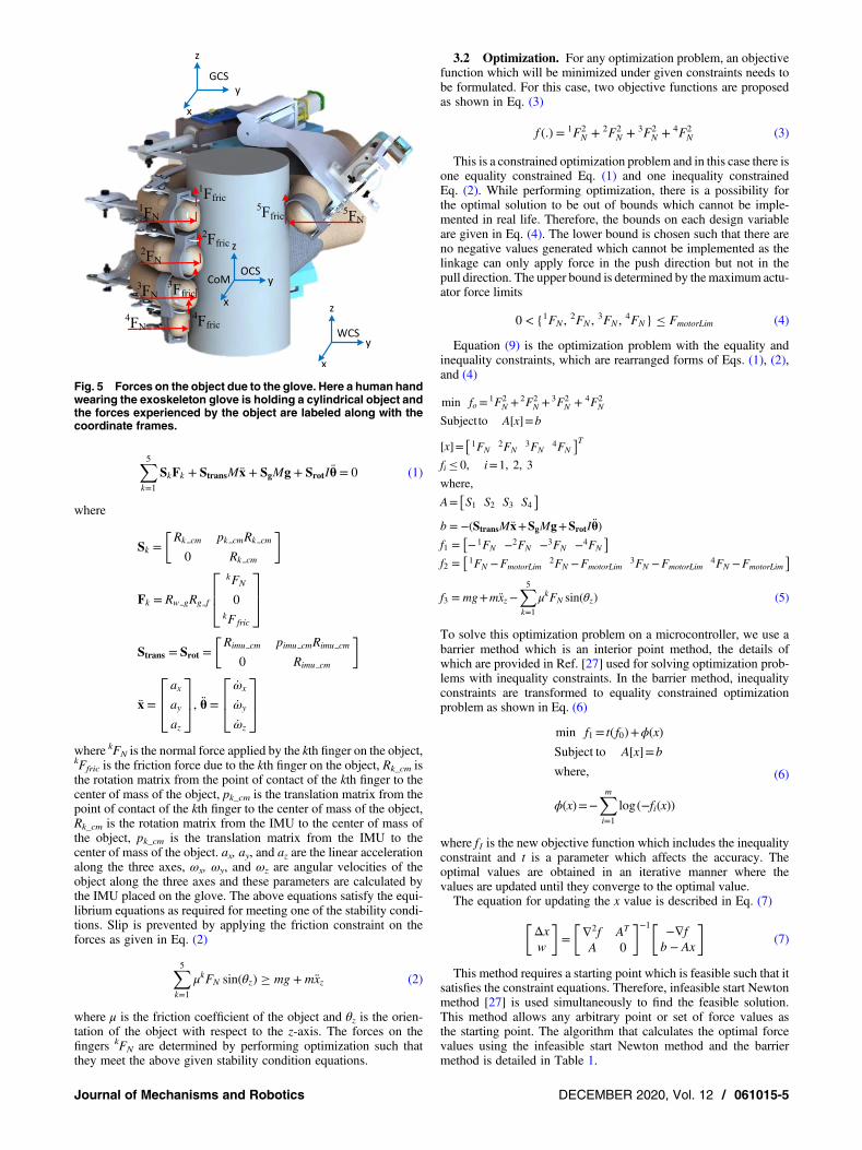
3.1 Dynamics Modeling of the Grasp. The dynamics ofgrasping an object needs to be analyzed which will be used in theoptimization as constraint equations. The forces are labeled inFig. 5where a human handwearing the exoskeleton glove is graspinga cylindrical object. Here, various coordinate frames are definedwhich include the world coordinate system, object coordinatesystem, and glove coordinate system. The contact forces arerelated by Eq. (1) where it satisfies the force andmoment equilibrium
Fig. 2 Flowchart describing the deformation detection algorithm. There are two states for thesystem, initially in State 1 the glove is in grasping stage and in State 2, deformation is measuredby the system and accordingly adjusts the force being applied.
Journal of Mechanisms and Robotics DECEMBER 2020, Vol. 12 / 061015-3

Fig. 3 FEA analysis of thin film cylindrical object. This analysis shows a thin film cylinder and normal forces are applied in FEAsoftware. Upon iteratively increasing the force applied, deformation is found to increase in a linear manner.
Fig. 4 Comparison plots between using deformation detection algorithm and force control. For this simulation, alinear mass-spring model was used as a model for the object to be grasped. Simulation results are shown for fourstiffness values and from observation the algorithm affects the force in larger magnitude for softer objects.
061015-4 / Vol. 12, DECEMBER 2020 Transactions of the ASME
∑5k=1
SkFk + StransMx + SgMg + SrotIθ = 0 (1)
where
Sk =Rk cm pk cmRk cm
0 Rk cm
[ ]
Fk = Rw gRg f
kFN
0kF fric
⎡⎢⎣
⎤⎥⎦
Strans = Srot =Rimu cm pimu cmRimu cm
0 Rimu cm
[ ]
x =
axayaz
⎡⎢⎣
⎤⎥⎦, θ =
ωx
ωy
ωz
⎡⎢⎣
⎤⎥⎦
where kFN is the normal force applied by the kth finger on the object,kFfric is the friction force due to the kth finger on the object, Rk_cm isthe rotation matrix from the point of contact of the kth finger to thecenter of mass of the object, pk_cm is the translation matrix from thepoint of contact of the kth finger to the center of mass of the object,Rk_cm is the rotation matrix from the IMU to the center of mass ofthe object, pk_cm is the translation matrix from the IMU to thecenter of mass of the object. ax, ay, and az are the linear accelerationalong the three axes, ωx, ωy, and ωz are angular velocities of theobject along the three axes and these parameters are calculated bythe IMU placed on the glove. The above equations satisfy the equi-librium equations as required for meeting one of the stability condi-tions. Slip is prevented by applying the friction constraint on theforces as given in Eq. (2)
∑5k=1
μkFN sin(θz) ≥ mg + mxz (2)
where μ is the friction coefficient of the object and θz is the orien-tation of the object with respect to the z-axis. The forces on thefingers kFN are determined by performing optimization such thatthey meet the above given stability condition equations.
3.2 Optimization. For any optimization problem, an objectivefunction which will be minimized under given constraints needs tobe formulated. For this case, two objective functions are proposedas shown in Eq. (3)
f (.) = 1F2N + 2F2
N + 3F2N + 4F2
N (3)
This is a constrained optimization problem and in this case there isone equality constrained Eq. (1) and one inequality constrainedEq. (2). While performing optimization, there is a possibility forthe optimal solution to be out of bounds which cannot be imple-mented in real life. Therefore, the bounds on each design variableare given in Eq. (4). The lower bound is chosen such that there areno negative values generated which cannot be implemented as thelinkage can only apply force in the push direction but not in thepull direction. The upper bound is determined by themaximum actu-ator force limits
0 < {1FN , 2FN , 3FN , 4FN} ≤ FmotorLim (4)
Equation (9) is the optimization problem with the equality andinequality constraints, which are rearranged forms of Eqs. (1), (2),and (4)
min fo= 1F2N +
2F2N +
3F2N + 4F2
N
Subject to A[x]=b
[x]= 1FN2FN
3FN4FN
[ ]Tfi ≤ 0, i=1, 2, 3
where,
A= S1 S2 S3 S4[ ]
b = −(StransMx+SgMg+SrotIθ)f1 = −1FN −2FN −3FN −4FN
[ ]f2 = 1FN −FmotorLim
2FN −FmotorLim3FN −FmotorLim
4FN −FmotorLim
[ ]
f3 = mg+mxz−∑5k=1
μkFN sin(θz) (5)
To solve this optimization problem on a microcontroller, we use abarrier method which is an interior point method, the details ofwhich are provided in Ref. [27] used for solving optimization prob-lems with inequality constraints. In the barrier method, inequalityconstraints are transformed to equality constrained optimizationproblem as shown in Eq. (6)
min f1= t( f0)+ϕ(x)
Subject to A[x]=b
where,
ϕ(x)=−∑mi=1
log(−fi(x))
(6)
where f1 is the new objective function which includes the inequalityconstraint and t is a parameter which affects the accuracy. Theoptimal values are obtained in an iterative manner where thevalues are updated until they converge to the optimal value.The equation for updating the x value is described in Eq. (7)
Δxw
[ ]= ∇2f AT
A 0
[ ]−1 −∇fb − Ax
[ ](7)
This method requires a starting point which is feasible such that itsatisfies the constraint equations. Therefore, infeasible start Newtonmethod [27] is used simultaneously to find the feasible solution.This method allows any arbitrary point or set of force values asthe starting point. The algorithm that calculates the optimal forcevalues using the infeasible start Newton method and the barriermethod is detailed in Table 1.
Fig. 5 Forces on the object due to the glove. Here a human handwearing the exoskeleton glove is holding a cylindrical object andthe forces experienced by the object are labeled along with thecoordinate frames.
Journal of Mechanisms and Robotics DECEMBER 2020, Vol. 12 / 061015-5

The above algorithm was implemented in MATLAB and all theforce values converged approximately in around 30 iterations asshown in Fig. 6 and the algorithm when implemented on teensy3.6 microcontroller, it took 12 ms to compute 30 iterations.
4 Controls ArchitectureThe force reference values for each actuator are generated by the
optimization algorithm as described in Sec. 3.2. These referenceforce values are sent to a controller that drives the SEA towardthe reference force value. The overall control architecture isshown Fig. 7 where there are five actuators each with their own con-troller. To design the controller for the SEA, a transfer function ofthe SEA needs to be derived. Viscous friction was assumed to bepresent in the actuator. In the transfer function for free motion ofthe linkage mechanism as given in Eq. (8), the unknown parameters
are the viscous friction coefficient b and the Inertia J as observed bythe motor
θmV
=kt
s2JR + s(bR + kvkt)(8)
where θm is the motor position (rad), R is the motor resistance, kt isthe torque constant of the motor, kv is the motor velocity constant, Jis the effective inertia, and b is the effective viscous coefficient.Estimation of these two parameters is achieved by using system
identification technique. System identification requires input andoutput data either in the time-domain or the frequency domainbased on which the transfer function of the plant is estimatedsuch that it best matches with the output for the given input.These data are acquired by sending a constant input voltage to the
motor and measuring the linear position with respect to time. Thesedata are fed into the system identification application in MATLAB toestimate the transfer function. In Fig. 8, we can observe that theoutput of the transfer function is approximately matching with themeasured output data for all four actuators.Motor controller is designed based on the estimated transfer
functions. The output results of a tuned PID (proportional-integral-derivative) and PI (proportional-integral) controller in SIMULINK
were similar so a PI controller was selected for the sake of implemen-tation simplicity. The rise time approximately for all four linkages isaround 0.6 s. The PI controller gains are tuned in SIMULINK using PIDtuner and the model was built using the transfer function that includesthe dynamics of the spring in the linear SEA as given in Eq. (9)
θmV
=kl
s2JR/kt + s(bR + kvkt)/kt + Rksk2l /kt
kl =P
2πN
(9)
Table 1 Optimal force algorithm
Input : choose arbitrary x such that, x ɛ dom ( f0) and fi(x)< 0 is satisfiedInput object properties such as mass, inertia etc.Define parameters like motor limits, distance between linkagesRead IMU data and fetch current acceleration and orientation of theobject
Setup : Formulate new objective function f1 as given in Eq. (6)Define the equality constraint equation matrices A and b
for i= 1 : 301. Find Δx using Eq. (7)2. Update x= x+Δx3. Repeat step 1 with updated x value; Update i ++
endOutput : Optimal force values—x
Fig. 6 Force convergence results of the optimization. Optimization used to generate the optimal set of forces for the four fingersis implemented initially on MATLAB and as can be observed the values converge to their optimal value in less than 30 iterations.
061015-6 / Vol. 12, DECEMBER 2020 Transactions of the ASME

where P is the pitch of the leadscrew, N is the gear ratio of the gear-head of the motor, and ks is the stiffness constant of the spring in theSEA.The transfer function is used to build the feedback physical
model in SIMULINK and is used to tune the PI gain parameters.The results of the tuned controller are briefly described in Table 2.The force measured by the SEA is nonlinearly related to the force
that is being applied at the tip of the finger where the object is beinggrasped. Therefore, a Jacobian transformation was applied to relatethe force exerted by the SEA and the force applied at the fingertip.Equation (10) describes the relation between the input and output ofthe controller and the relation between the force measured by SEAand fingertip force
ei = iFd − iFm i = 1, 2, 3, 4
iFd = JiiFN
iFm = kspr(id pot − ciθm)
ui = ikpei + ikint
∫eidt
(10)
where iFm is the measured force by the SEA, iFd is the desired ref-erence force by the SEA, kspr is the SEA spring constant, idpot is thelinear potentiometer measurement, and iθm is the motor positionmeasured by the magnetic hall-effect encoder.The Jacobian (J) for each finger is derived using the dynamics
model developed in Ref. [2]. As can be seen, the dynamics modelis highly nonlinear and its direct implementation on a microcontrol-ler will pose computational issues. An approximate second-orderpolynomial model was fitted to the analytical dynamics model asshown in Fig. 9 and will be used in the Jacobian.
5 Prototype IntegrationThe RML glove was designed in SolidWorks and manufactured
and integrated as shown in Fig. 10 to test both algorithms described
earlier. The glove base structure and most of the SEA parts includ-ing the screw-nut were manufactured using a 3D printer. The link-ages were manufactured from a 0.8 mm thick aluminum sheet usinga 2.5D milling machine so that it is sufficiently strong and light-weight. Direct current brushed motors were used with 250:1gearbox that run on 12 V power supply with stall torque of0.3 N m. For measuring the motor position, magnetic hall-effectencoders were used which provide 12 counts per revolution ofmotor shaft. The output of the SEA was measured using a linearpotentiometer with 20 mm travel length. The actuators were con-trolled using teensy 3.6 microcontroller which also runs the defor-mation detection algorithm and optimal force algorithm. Themicrocontroller sends the motor pulse width modulation signalsto the motor driver (by TI DRV8801), which can deliver a contin-uous current of 1 A and can operate between 8 V and 36 V.MPU-9250 by InvenSense IMU was used for measuring the ori-
entation and acceleration of the glove. It is a nine-axis motion track-ing device that combines a three-axis magnetometer, three-axisaccelerometer, and three-axis gyrometer. Magnetometer providesorientation of the device with respect to the magnetic north, theaccelerometer provides the gravity and linear acceleration measure-ments along the three axes, and the gyrometer provides angularvelocity about the three axes. Figure 11 describes the prototypealong with all individual components used in building it.Exponential smoothing method was used to remove noise from
all the sensors including the IMU, linear potentiometer, and mag-netic hall-effect encoders.
6 Experimental Setup and Results6.1 Deformation Detection. In this test, a deformation detec-
tion algorithm was implemented and tested on the glove. Three dif-ferent objects were selected with different stiffnesses for the testincluding a plastic water bottle, a polycoated paper cup, and aplastic cup.Initial tests were carried out on these objects to quantitatively
measure the stiffness of the objects. The test setup as shown in
Fig. 7 Overall control architecture of the glove. This describes the data flow for thisalgorithm where data from the IMU are read by the algorithm and generates optimalset of forces. This optimal force values are sent to each actuator as a reference forcewhich is tracked by the controller.
Journal of Mechanisms and Robotics DECEMBER 2020, Vol. 12 / 061015-7

Fig. 8 Results of system identification of the four actuators. (a) Input voltage 8.2 V, (b) inputvoltage 5.6 V, and (c) input voltage 3 V. Second-order transfer function was estimated basedupon the step response of the actuator. Estimation was performed in MATLAB. The inertia andviscous parameters are calculated by comparing the physical transfer function with the estimatedtransfer function.
061015-8 / Vol. 12, DECEMBER 2020 Transactions of the ASME

Fig. 12 includes a linear actuator with a force sensitive resistor(FSR) at its tip. The linear servo actuator was placed against thesurface of the object such that it was slightly touching.Then the linear actuator was commanded to move forward such
that it pushes against the object while deforming it. The FSR wasused to calculate the force applied by the linear actuator on theobject and the potentiometer was used to calculate the distance trav-eled by the linear actuator which is also the deformation of theobject. This test was carried out for all three objects and theresults of the tests are depicted in Fig. 13. The measured data isfitted to a linear curve and is plotted along with it for comparison.By observation, it is clear that the plastic water bottle is stifferthan the poly coated paper cup which is also stiffer than theplastic cup. Since the stiffness properties of the objects wereobtained, the subsequent tests with the glove were performed.The deformation detection algorithm was implemented and thedeformation is measured. Initially the glove was positioned nearthe object to be grasped and all the linkages were fully extendedso they are not touching the object. Then, constant velocity inputwas applied in a feedforward manner, such that the fingers startflexing and closing on the object. As soon as the finger makescontact with the object, the contact is detected based on the accel-eration spike observed in the linear potentiometer measurementsas shown in Fig. 14. The particular linkage upon making contactwith the object halts the flexion and waits until all the fingersachieve contact. After all the fingers make contact, the deformationdetection algorithm is engaged and the glove starts grasping theobject with predefined forces. It is assumed that the user does notmove the fingers until the deformation detection algorithm isengaged. But this requirement can be eliminated by using a refer-ence force after the fingers make contact to readjust them in theevent that the user may mistakenly move the fingers. While per-forming this grasp, the linear potentiometer and magnetic hall-effectencoder readings are measured and stored for analysis. This test wasrepeated for all three objects and all the measurements were stored.This test was repeated for all three objects with only the force
control implemented results that were used for comparison withthe former test results.As can be seen in Fig. 15, the plots are arranged in increasing
stiffness of the object and the gap between the deformation forforce control and deformation detection algorithm is decreasingwith increasing stiffness as observed in the simulation results.This proves that the algorithm decreases the force applied propor-tional to the softness of the object.
6.2 Optimal Force Algorithm. Tests where the forces fromthe optimization are compared with forces produced by a humanhand were performed. The test setup includes an object (waterbottle) and four FSR sensors are attached on the bottle surface atknown relative distances as shown in Fig. 16. An IMU is attachedon the object at known distance from the region of grasp. Then thebottle is held by a healthy hand such that the four fingers are on topof the four FSR sensors. Three sets of experiments were performed:(1) hold the bottle in the air without any movement, (2) hold thebottle up and then translate in the direction of the force appliedby the fingers back and forth three to four times, and (3) hold thebottle up and rotate the bottle in both clockwise and counter-clockwise direction.While performing these tests, inertial data from the IMU and force
data from the FSR are stored for post-processing. Hardware-in-loop
Table 2 Tuned controller results
Index Middle Ring Pinky
Bandwidth (Hz) 1.42 1.52 1.47 1.22Rise time (s) 0.17 0.16 0.15 0.2Settling time (s) 0.27 0.27 0.23 0.37Overshoot (%) 0.74 0.23 1.74 0.02
Fig. 9 Variation of tip force with joint angle. Here for a fixed input force of 15 N, the tipforce is calculated analytically as the joint angle is increased. A second-order polynomialfunction is fitted to that analytic curve so that the polynomial function can be implementedin a microcontroller.
Fig. 10 RML glove prototype built to test the stable grasp algo-rithms including the deformation detection algorithm andoptimal force algorithm
Journal of Mechanisms and Robotics DECEMBER 2020, Vol. 12 / 061015-9

(HIL) simulation was performed where the data from the IMU waspassed through the optimal force algorithm to generate the force distri-bution across the four fingers. Upon comparing the experimental dataand the HIL simulation data as shown in Figs. 17–19; it can beobserved that for all three cases the middle and ring finger forcesmatch with greater accuracy. However, the pinky finger force hadless matching pattern in terms of force magnitude. This test wasdone to check the ability of the algorithm in producing human likeforces. It can be concluded that two out of four fingers exhibitedacceptable matching in force magnitudes. The index finger matchespartially with the experimental data and pinky finger demonstratesthe lowest matching. This lower matching could be due to distributionof forces generated by the brain did not exactly follow the optimizationmethod used, and even if it did, the objective function could be morecomplicated than the one used in the algorithm.The algorithm was then implemented on the RML glove for
testing. For the test, a water bottle was used as shown in Fig. 20for grasping by the exoskeleton glove. Two tests were performed:(1) predefined grasp force was applied and the object was held sta-tionary and (2) initially the object was lifted after applying a prede-fined grasp after which it was slowly rotated 90 deg clockwise andthen back to the original position. The forces for each finger weredetermined by the optimization algorithm and the inertial datafrom the IMU.
From Fig. 21, it can be observed that all the fingers of the glovereach the desired force with a small steady-state error. The rise timeis approximately 1.5 s which is due to motor and power limitations.In the object rotation part of the test as shown in Fig. 22, the
desired force is changing as it is rotated and the SEAs have
Fig. 12 Object material testing setup. This test setup was builtto measure experimentally the stiffness of the three testobjects using a linear actuator and FSR. These objects will belater used to perform the deformation detection test.
Fig. 13 Measured stiffness plot. Results of the material testing for the three objects areshown. A linear curve is fitted to the experimental plot and there is clear distinctionbetween the stiffnesses of the three objects.
Fig. 11 Overall hardware architecture. The exoskeleton glove is communicating with acomputer and the user for operation of the glove and analysis of data.
061015-10 / Vol. 12, DECEMBER 2020 Transactions of the ASME

approximately followed the profile. There was small delaybetween changes occurring in the desired force and the measuredforce which is due to motor velocity and power limitations as men-tioned earlier.
7 Conclusion and Future WorkIn this research, novel algorithms were developed which improve
the grasp stability of an exoskeleton glove by using minimalnumber of sensors and low computational power. The algorithmshelped improve the stability of grasp in two major ways: (1) detect-ing any deformation in the object while grasping and minimizing it,and (2) adjusting the force distribution among the fingers such thatthe force and moment equilibriums are maintained. Deformation isdetected based upon tracking of the potentiometer and encoderreadings and then decreasing the set point force value to preventfurther deformation. The force optimal algorithm developed usedinformation from the sensors and the IMU to calculate an optimaldistribution of forces that satisfy the force and moment equilibri-ums. The Barrier method along with the infeasible start newtonmethod was used for optimization and was implemented in ateensy microcontroller. It took 12 ms to run the optimization algo-rithm and was fast enough to have negligible errors. A full
Fig. 14 Contact detection. The glove has initiatedmotion and upon contact with anobject, there is a spike observed in the acceleration as measured by the linearpotentiometer.
Fig. 15 Measured deformation algorithm response. The deformation detection algorithm istested on the three objects and the linear potentiometer response is plotted against time.Response of the potentiometer when the algorithm is not implemented is also plotted forcomparison.
Fig. 16 Hand optimal test setup. This test setup was used tomeasure and compare the forces produced by human handwith forces generated by the optimization method.
Journal of Mechanisms and Robotics DECEMBER 2020, Vol. 12 / 061015-11

prototype was manufactured and integrated and was used to test andvalidate the proposed algorithms. The deformation detection algo-rithms implemented on the prototype produced similar results com-pared with the simulation. The glove was able to differentiatebetween objects with different stiffnesses and was able to reducethe deformation compared with when the algorithm was not imple-mented. The deformation reduction was higher for soft objects com-pared with rigid objects. Then the optimal grasp algorithm wasimplemented which, for known mass properties of the object, calcu-lates the optimal forces for the four fingers. The thumb finger actedas a rigid support and provided a reaction force. Initial tests compar-ing the simulation results with a human hand showed a good matchfor two fingers and close similarity for the other two fingers. Theglove performance was then tested for this algorithm.Future research includes combining both algorithms so that they
run simultaneously. Integration of rotary SEA or some other form of
sensor for autonomous estimation of the mass of the object andother properties will be performed. Improvements in mechanicaldesign of the glove will be performed such that it is lighter andmore compact. Machine learning techniques can be applied toimprove the performance of these algorithms. Further researchcan be performed by analyzing the computational cost, complexity,accuracy of the nonlinear constrained optimization method, resultsof which can be used to further improve the optimization method.In-depth study of friction characteristics needs to be performed toeliminate the delay issue and also experiment with differentsliding materials in the linear actuator so as to have uniform frictioncharacteristics that is not affected by the load, velocity, or positionof the SEA. In addition, online stiffness measurement of the objectsbeing grasped will be implemented using the sensor measurementsafter performing calibration tests so that the stiffness measuredaccurately represents the actual stiffness of the object.
Fig. 17 Hand optimal test for holding. The forces generated by the human hand when grasping abottle are compared with the forces as produced by the optimal force algorithm where the input isthe total force produced by human hand. In this case the object is not being manipulated.
Fig. 18 Hand optimal test for translation. In this case the object was held and then translated inthe horizontal direction in an oscillatory manner.
061015-12 / Vol. 12, DECEMBER 2020 Transactions of the ASME

Fig. 19 Hand optimal test for rotation. In this case the object was held by hand then rotatedin an oscillatory manner.
Fig. 20 Prototype glove shown here was used for testing the optimal force algorithm.The object in this case the water bottle is grasped and then the forces are applied asgenerated by the algorithm.
Fig. 21 Experimental results for holding are shown here where the object grasped is heldstationary and no motion is imparted to the object. The desired force as generated by theoptimization method is compared with actual force measured.
Journal of Mechanisms and Robotics DECEMBER 2020, Vol. 12 / 061015-13

AcknowledgmentThis work was supported in part by the Eunice Kennedy Shriver
National Institute of Child Health and Human Development of theNational Institutes of Health under Award Number R21HD095027.The content is solely the responsibility of the authors and does notnecessarily represent the official views of the National Institutes ofHealth.
Data Availability StatementThe authors attest that all data for this study are included in the
paper. Data provided by a third party listed in Acknowledgment.No data, models, or code were generated or used for this paper.
References[1] Refour, E., Sebastian, B., and Ben-Tzvi, P., 2018, “Two-Digit Robotic
Exoskeleton Glove Mechanism: Design and Integration,” ASME J. Mech.Rob., 10(2), p. 025002.
[2] Vanteddu, T., Sebastian, B., and Ben-Tzvi, P., 2018, “Design Optimization ofRML Glove for Improved Grasp Performance,” Proceedings of the ASME2018 Dynamic Systems and Control Conference (DSCC 2018), Atlanta, GA,Sept. 30–Oct. 3, pp. 1–8.
[3] Lee, S. W., Landers, K. A., and Park, H., 2014, “Development of a BiomimeticHand Exotendon Device (BiomHED) for Restoration of Functional HandMovement Post-Stroke,” IEEE Trans. Neural Syst. Rehabil. Eng., 22(4),pp. 886–898.
[4] In, H., Kang, B. B., Sin, M., and Cho, K., 2015, “Exo-Glove: A Wearable Robotfor the Hand With a Soft Tendon Routing System,” IEEE Rob. Autom. Mag.,22(1), pp. 97–105.
[5] Nycz, C. J., Delph, M. A., and Fischer, G. S., 2015, “Modeling and Design of aTendon Actuated Soft Robotic Exoskeleton for Hemiparetic Upper LimbRehabilitation,” 2015 37th Annual International Conference on IEEEEngineering in Medicine and Biology Society (EMBC), Milan, Aug. 25–29,pp. 3889–3892.
[6] Ben-Tzvi, P., Danoff, J., and Ma, Z., 2016, “The Design Evolution of a Sensingand Force-Feedback Exoskeleton Robotic Glove for Hand RehabilitationApplication,” J. Mech. Rob., 8(5), pp. 1–9.
[7] Iqbal, J., Khan, H., Tsagarakis, N. G., and Caldwell, D. G., 2014, “ScienceDirectA Novel Exoskeleton Robotic System for Hand Rehabilitation—Conceptualization to Prototyping,” Integr. Med. Res., 34(2), pp. 79–89.
[8] Agarwal, P., Fox, J., Yun, Y., O’Malley, M. K., and Deshpande, A. D., 2015, “AnIndex Finger Exoskeleton With Series Elastic Actuation for Rehabilitation:Design, Control and Performance Characterization,” Int. J. Rob. Res., 34(14),pp. 1747–1772.
[9] Howard, W. S., and Kumar, V., 1996, “On the Stability of Grasped Objects,”IEEE Trans. Rob. Autom., 12(6), pp. 904–917.
[10] Nakashima, A., Yoshimastsu, Y., and Hayakawa, Y., 2010, “Analysis andSynthesis of Stable Grasp by Multi-Fingered Robot Hand,” IEEE InternationalConference on Control Application, Yokohama, Japan, Sept. 8–10, pp. 1582–1589.
[11] Lu, Y., Zhang, C., Cao, C., and Liu, Y., 2017, “Analysis of Coordinated GraspingKinematics and Optimization of Grasping Force of a Parallel Hybrid Hand,”Int. J. Adv. Rob. Syst., 14(3), pp. 1–14.
[12] Bekiroglu, Y., Laaksonen, J., Jorgensen, J. A., Kyrki, V., and Kragic, D., 2011,“Assessing Grasp Stability Based on Learning and Haptic Data,” IEEE Trans.Rob., 27(3), pp. 616–629.
[13] Kinoshita, H., Murase, T., and Bandou, T., 1996, “Grip Posture and ForcesDuring Holding Cylindrical Objects With Circular Grips,” Ergonomics, 39(9),pp. 1163–1176.
[14] Dang, H., and Allen, P. K., 2012, “Learning Grasp Stability,” 2012 IEEEInternational Conference on Robotics and Automation, Saint Paul, MN, May14–18, pp. 2392–2397.
[15] Kragten,G.A.,Baril,M.,Gosselin,C.,andHerder,J.L.,2011,“StablePrecisionGraspsby Underactuated Grippers,” IEEE Trans. Rob., 27(6), pp. 1056–1066.
[16] Suhaib, M., Khan, R. A., and Mukherjee, S., 2011, “Contact Force Optimizationfor Stable Grasp of Multifingered Robotic Grippers,”World Congr. Eng., III, pp.2194–2197.
[17] Haas-Heger, M., Iyengar, G., and Ciocarlie, M., 2018, “Passive Reaction Analysisfor Grasp Stability,” IEEE Trans. Autom. Sci. Eng., 15(3), pp. 955–966.
[18] Lee, B. J. B., Williams, A., Ben-tzvi, P., and Member, S., 2018, “IntelligentObject Grasping With Sensor Fusion for Rehabilitation and AssistiveApplications,” IEEE Trans. Neural Syst. Rehabil. Eng., 26(8), pp. 1556–1565.
[19] Chauhan, R. J., and Ben-Tzvi, P., 2018, “Latent Variable Grasp Prediction forExoskeletal Glove Control,” Proceedings of the ASME 2018 Dynamic Systemsand Control Conference, Atlanta, GA, Sept. 30–Oct. 3, p. V001T07A002.
[20] Chauhan, R., Sebastian, B., and Ben-Tzvi, P., 2020, “Grasp Prediction TowardsNaturalistic Exoskeleton Glove Control,” IEEE Trans. Human-Mach. Sys., 50(1),pp. 22–31.
[21] Howard, A. M., and Bekey, G. A., 2000, “Intelligent Learning for DeformableObject Manipulation,” Auton. Rob., 9(1), pp. 51–58.
[22] Cretu, A., Payeur, P., and Petriu, E. M., 2012, “Soft Object DeformationMonitoring and Learning for Model-Based Robotic Hand Manipulation,” IEEETrans. Syst. Man, Cybern. Part B, 42(3), pp. 740–753.
[23] Drimus, A., Kootstra, G., Bilberg, A., andKragic, D., 2011, “Classification of Rigidand Deformable Objects Using a Novel Tactile Sensor,” 2011 15th InternationalConference on Advanced Robotics, Tallinn, June 20–23, pp. 427–434.
[24] Khalil, F. F., Payeur, P., and Cretu, A.-M., 2010, “Integrated MultisensoryRobotic Hand System for Deformable Object Manipulation,” IASTEDTechnology Conferences/705: ARP/706: RA/707: NANA/728: CompBIO,Cambridge, MA, Nov. 1–3, pp. 159–166.
[25] Delgado, A., Jara, C. A., Mira, D., and Torres, F., 2015, “A Tactile-BasedGrasping Strategy for Deformable Objects Manipulation and DeformabilityEstimation,” 2015 12th International Conference on Informatics in ControlAutomation and Robotics, Colmar, France, July 21–23, vol. 2, pp. 369–374.
[26] Huang, J., Todo, I., and Yabut, T., 2005, “Position/Force Hybrid Control of aManipulator With a Flexible Tool Using Visual and Force Information,”Cutting Edge Robotics, Pro Literatur Verlag, Germany.
[27] Boyd, S., and Vandenberghe, L., 2004, Convex Optimization, CambridgeUniversity Press, Cambridge, UK.
Fig. 22 Test results for rotation shown here for when the glove is grasping the object and thenrotated about horizontal axis. The IMU measures the change in orientation and the optimizationmethod generates the desired force profile as required.
061015-14 / Vol. 12, DECEMBER 2020 Transactions of the ASME