Stabilization of the calibration signal frequency Vitaly Stepin Dmitry Stepin Jevgeny Boole.
12
Stabilization of the calibration signal frequency Vitaly Stepin Dmitry Stepin Jevgeny Boole
-
Upload
charles-washington -
Category
Documents
-
view
222 -
download
1
Transcript of Stabilization of the calibration signal frequency Vitaly Stepin Dmitry Stepin Jevgeny Boole.

Stabilization of the calibration signal frequency
Vitaly Stepin
Dmitry Stepin
Jevgeny Boole

Problem to be solved
T_EXT ~ 14usPeriod of the calibration signal T_VCO is varied in range 17.876 859 … 17.876 880 us
Different measurement results of the RMS jitter at different frequencies of the calibration signal
Period of the calibration signal must be fixed for satisfactory
measurement results

Block diagram of the VCO period adjustment
PC
EPP (control + data + flags)
Timer
FPGA
VCO module Calibration generator
VCO signal
FIFO
Control
EnWrite
External signal
ADC
Logic
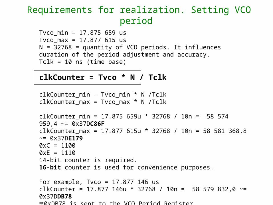
Requirements for realization. Setting VCO period
Tvco_min = 17.875 659 usTvco_max = 17.877 615 usN = 32768 = quantity of VCO periods. It influences duration of the period adjustment and accuracy. Tclk = 10 ns (time base)
clkCounter = Tvco * N / Tclk
clkCounter_min = Tvco_min * N /TclkclkCounter_max = Tvco_max * N /Tclk
clkCounter_min = 17.875 659u * 32768 / 10n = 58 574 959,4 ~= 0x37DC86FclkCounter_max = 17.877 615u * 32768 / 10n = 58 581 368,8 ~= 0x37DE1790xC = 11000xE = 111014-bit counter is required.16-bit counter is used for convenience purposes.
For example, Tvco = 17.877 146 usclkCounter = 17.877 146u * 32768 / 10n = 58 579 832,0 ~= 0x37DDB78 0xDB78 is sent to the VCO Period Register (clkCounterRef)
VCO period step is < 0.3ps (10ns / 32768) => accuracy +\- 0.15ps

Operation principles
COMSEL (6)
clkCounter
clkCounterRef-1
+1
EnWrite
DAC value
0x000
0xFFF
UpdateDAC value
Previous -1 -1 -1 -1 DAC value is not updated (period is locked)
EnVCO
10ms
Period is locked
Update interval65536 periods ~1.2s
32768 eventsfor transient ~0.6s
32768 eventsfor period meas. ~0.6s
~0.5ps

RMS jitter dependence on VCO signal period.Test setup
Calibrationgenerator
External signal T_EXT = const ~= 14 us
Logic
T_VCO is variable
ADC
Finding a “good”VCO frequency

Signal RMS jitter versus VCO period (a rough estimation)
step 0.21ps 10 iterations per step
signal period ~14us)
T_VCO = 17.877 120...17.877 140us
T_VCO = 17.877 140...17.877 160us
T_VCO = 17.877 160...17.877 180us

Signal RMS jitter versus VCO period (a fine estimation)
T_VCO = 17.877 144 ... 17.877 150us (step 0.21ps, 400 iterations per step, signal period ~14us)
Assumed as a “good” period/frequency

Testing “good” frequency over 5 ... 40oCT_VCO = 17.877 146 us (10 000 iterations, signal period ~14us)
VCO period error, ps
Internaltemperature,“C
Signal RMSJitter, ps

RMS jitter dependence on external signal period.Test setup
Calibrationgenerator
External signalT_EXT = 20.476 231 ... 20.483 761 us
Logic
T_VCO = 17.877 146 us
ADC
A “good”frequency

RMS jitter dependence on external signal period. Experimental results
T_VCO = const = 17.877 146 us (good” frequency) T_EXT = 20.476 231 ... 20.483 761 us (ETTG, 8-bit resolution, 20 iterations for each k = 0 ... 255)
External signal period, ps
External signal RMS jitter, ps
VCO period error, ps

Conclusion
• VCO period couldn’t be selected in an arbitrary way. It is possible to set period of the VCO generator with high precision.
Precision of the VCO period depends on N and DAC resolution (in general, even 0.1ps is not a limit but so high resolution is not required). Adjustment time depends on N.
VCO period can be simply updated from PC software via EPP port.
• Only several narrow gaps for “good” frequencies (not more than 4ps) are found. 800ps of the VCO period were tested (period of the VCO signal can be changed in ~2000ps interval). Wider intervals should be found for more reliable operation.
• Time base (10ns) must be very precise!!!
• Experimental results show that VCO period is fixed with expected precision. The “good” frequency seems to be OK.
• No changes in PC software are necessary for calibration data acquisition => compatible with older version
• RMS jitter may also depend on frequency of the external signal.