Stabilization of sulphide soil with lime-cement columns by...
6
Stabilization of sulphide soil with lime- cement columns by the river Keräsjoki T. Sundqvist 1 1 Tyréns AB, Kalix, Sweden ABSTRACT Stabilization with lime-cement mixtures in loose fine sediments has long been an accepted and well-used method in southern and central Sweden. Along the coast by the Gulf of Bothnia the soil consists largely of fine sediments by sulphide soil. Lime-cement stabilization of sulphide soil has a reputation in Sweden to be fraught with risks due to the sulphide soil material properties. The rumour was created in part by a landslide, in the late 90’s, in lime-cement stabilized sulphide soil during the construction of the road E4 in the southern parts of the coastal area along the Gulf of Bothnia. The sulphide soil is in some cases considered as hazardous waste, according to Swedish environ- mental rules, which makes the commonly occurring soil reinforcement method excavation and refill economically unreasonable because of the disposal costs of hazardous waste. The result of both the mixing experiment and the field studies show a clear increasing of the shear strength in the sulphide soil. Detailed design is ongoing and the construction work is planned to the summer of 2017. The preconditions for a successful project are big which gives the already well-known technique is great potential even in sulphide soil in the future. The tech- nique can be very useful in case of any major infrastructure projects along the major parts of the coastal area along the Gulf of Bothnia where up to 20 meters thick sediments with sulphide are common. 1 INTRODUCTION Commissioned by the Swedish Transport Admin- istration has Tyréns AB been working with risk re- duction actions for the road 729 in the village Keräsjoki by the river Keräsjoki in the municipality of Haparanda. Parallel with the risk reduction project a research and development project financed by Swedish transport Administration on the same site performed by Tyréns AB. The target for the R & D project is to obtain a substantial increase in knowledge in deep stabilization with lime-cement mixtures in sulphide soil and in the extension design a solution for the road section in the risk reductions project. 1.1 Background Soil stabilization with lime-cement mixtures in loose fine sediment has long been a well-used method in southern and central of Sweden. Along the coast by the Gulf of Bothnia, from Gävle in the south up to Haparanda by the Finnish border, does the soil con- sists of loose fine sediments by sulphide and sul- phide-bearing soil. In some places the sulphide is varved. It should also be clarified that the sulphide soils material characteristics and layering varies along its long coastline. Stabilization with lime- cement columns in sulphide soil has a rumor to be fraught with risks due to the sulphide soil material properties. The rumor was created in part by a land- slide, in the late 90’s, in lime-cement stabilized sul- phide soil during the construction of the road E4 in 1
Transcript of Stabilization of sulphide soil with lime-cement columns by...

Stabilization of sulphide soil with lime-cement columnsby the river Keräsjoki
T. Sundqvist1
1 Tyréns AB, Kalix, Sweden
ABSTRACT
Stabilization with lime-cement mixtures in loose fine sediments has long been an accepted and well-used method in southern and centralSweden. Along the coast by the Gulf of Bothnia the soil consists largely of fine sediments by sulphide soil. Lime-cement stabilization ofsulphide soil has a reputation in Sweden to be fraught with risks due to the sulphide soil material properties. The rumour was created in partby a landslide, in the late 90’s, in lime-cement stabilized sulphide soil during the construction of the road E4 in the southern parts of thecoastal area along the Gulf of Bothnia. The sulphide soil is in some cases considered as hazardous waste, according to Swedish environ-mental rules, which makes the commonly occurring soil reinforcement method excavation and refill economically unreasonable because ofthe disposal costs of hazardous waste. The result of both the mixing experiment and the field studies show a clear increasing of the shearstrength in the sulphide soil. Detailed design is ongoing and the construction work is planned to the summer of 2017. The preconditions fora successful project are big which gives the already well-known technique is great potential even in sulphide soil in the future. The tech-nique can be very useful in case of any major infrastructure projects along the major parts of the coastal area along the Gulf of Bothniawhere up to 20 meters thick sediments with sulphide are common.
1 INTRODUCTION
Commissioned by the Swedish Transport Admin-istration has Tyréns AB been working with risk re-duction actions for the road 729 in the villageKeräsjoki by the river Keräsjoki in the municipalityof Haparanda. Parallel with the risk reduction projecta research and development project financed bySwedish transport Administration on the same siteperformed by Tyréns AB. The target for the R & Dproject is to obtain a substantial increase inknowledge in deep stabilization with lime-cementmixtures in sulphide soil and in the extension designa solution for the road section in the risk reductionsproject.
1.1 Background
Soil stabilization with lime-cement mixtures in loosefine sediment has long been a well-used method insouthern and central of Sweden. Along the coast bythe Gulf of Bothnia, from Gävle in the south up toHaparanda by the Finnish border, does the soil con-sists of loose fine sediments by sulphide and sul-phide-bearing soil. In some places the sulphide isvarved. It should also be clarified that the sulphidesoils material characteristics and layering variesalong its long coastline. Stabilization with lime-cement columns in sulphide soil has a rumor to befraught with risks due to the sulphide soil materialproperties. The rumor was created in part by a land-slide, in the late 90’s, in lime-cement stabilized sul-phide soil during the construction of the road E4 in
1
des0aso
Text Box
Proceedings of the 24th European Young Geotechnical Engineers Conference (EYGEC), Durham, UK Osman, A.S. & Toll, D.G. (Eds.) 2015 ISBN 978-0-9933836-01

the southern parts of the coastal area along the Gulfof Bothnia (Andersson & Norrman, 2004).
The sulphide soil is in some cases considered ashazardous waste, according to Swedish environmen-tal rules, which makes the commonly occurring soilreinforcement method excavation and refill economi-cally unreasonable because of the disposal costs ofhazardous waste.
Lime-Cement reinforcement would be a goodcomplement and also very likely to be price competi-tive compared with the traditional use, along the Gulfof Bothnia, of the grandfathered soil reinforcementmethod with settlement reduction wooden piles. Thewooden piles are often used in sulphide soil with athickness of 3 to 10 meters.
2 KERÄSJOKI
The area around the location has during several yearsbeen having stability problems. The soil in the areaconsists of a sulphide soil and to ensure the safety ofthe road has an idea with deep stabilization has beendrawn up. To gain knowledge and prove that themethod is possible, in those soil conditions, has a testfield been established in the summer of 2014 forstudies of the stabilization effects.
2.1 Orientation
In the northern most parts of the Gulf of Bothniaabout 10 kilometres from the Finnish border flowsthe river Keräsjoki out in the sea, see (Figure 1). Theriver Keräsjoki, which has its main catchment area ofwetland areas in the Municipality of Haparanda,flows through the village by the same name and ex-tends parallel with the road 729 in southbound direc-tion by the problem location.
Figure 1. Map and overview of Keräsjoki
2.2 History
The Swedish Transport Administration let TyrénsAB carry out a stability investigation as early as 2011in the area. The object in question consists of a 400meter long straight stretch which is wedged betweensome houses and the river. During the stability inves-tigation in 2011 did the landslide activity increase inthe river embankment along a limited distance of thestraight stretch. It resulted in a landslide in the slopeseparating the river and the road where the edge ofthe landslide ended up close to the road. The threat-ened part of the road were secured due to a 70 meterlong permanent tied back sheet pile wall to maintainstability against successively backward moving land-slides, see (Figure 2). For the other parts of the roadthe Swedish Transport Administration decided tokeep these under surveillance.
Figure 2. Tied back sheet pile wall installation in the roadside bythe landslide.
A stretch in area was identified to have clear signsof landslide activity in the roadside down toward theriver during late autumn 2013. The investigation tookat the back and further stability calculations showed apoor stability along the current route. To secure thestretch so were several proposals discussed to find aneconomic and technical feasible solution. As the ex-tent of this phase was over 300 meters long and themore, from a northernmost part of Sweden perspec-tive, "ordinary" slope stabilization actions were con-sidered unreasonable within the economic and tech-nical framework so suggested Tyréns to deepstabilize the route with an L/C-column solution. Ini-tially was a type design performed to see the approx-imate reinforcement distribution and to ensure stabil-ity problems were manageable. Different binder
2
variants and mixing amounts were first studied in thelaboratory and later on in a test field in Keräsjoki.
2.3 Geotechnical conditions
The soil in the area consists of a thin layer of humussoil above most nearly 0,5 meter sand. The sand isstored under the 0,5 to 1,5 meter thick silt which inturn is stored under a 9,0 to 12,0 meter thick layer ofclayey sulphide silt and silty sulphide clay which isresting on a silty sand till.
The sulphide soil along the stretch is relativelyhomogeneous when no clearly deviant layer is ob-served, however the clay content increases withdepth. Superficial is the sulphide soil a clayey sul-phide silt which then merges with the depth in a siltysulphide clay.
02468
1012
0,00 10,00 20,00 30,00 40,00 50,00
Dep
th(m
)
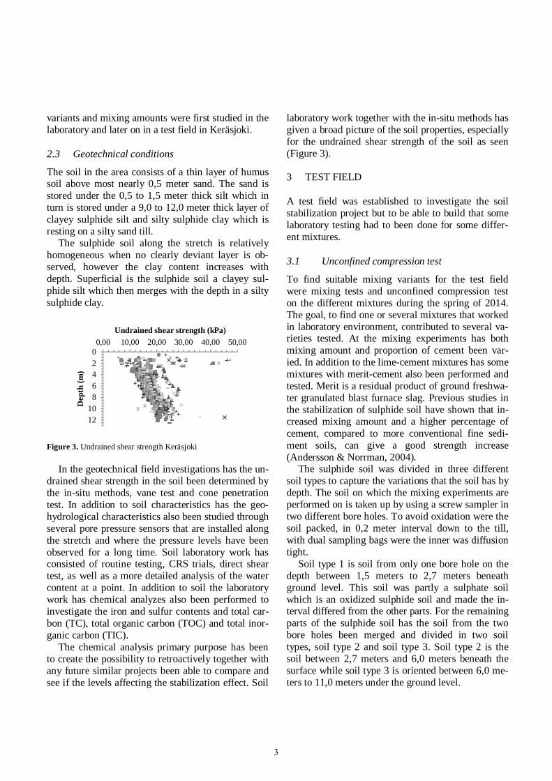
Undrained shear strength (kPa)
Figure 3. Undrained shear strength Keräsjoki
In the geotechnical field investigations has the un-drained shear strength in the soil been determined bythe in-situ methods, vane test and cone penetrationtest. In addition to soil characteristics has the geo-hydrological characteristics also been studied throughseveral pore pressure sensors that are installed alongthe stretch and where the pressure levels have beenobserved for a long time. Soil laboratory work hasconsisted of routine testing, CRS trials, direct sheartest, as well as a more detailed analysis of the watercontent at a point. In addition to soil the laboratorywork has chemical analyzes also been performed toinvestigate the iron and sulfur contents and total car-bon (TC), total organic carbon (TOC) and total inor-ganic carbon (TIC).
The chemical analysis primary purpose has beento create the possibility to retroactively together withany future similar projects been able to compare andsee if the levels affecting the stabilization effect. Soil
laboratory work together with the in-situ methods hasgiven a broad picture of the soil properties, especiallyfor the undrained shear strength of the soil as seen(Figure 3).
3 TEST FIELD
A test field was established to investigate the soilstabilization project but to be able to build that somelaboratory testing had to been done for some differ-ent mixtures.
3.1 Unconfined compression test
To find suitable mixing variants for the test fieldwere mixing tests and unconfined compression teston the different mixtures during the spring of 2014.The goal, to find one or several mixtures that workedin laboratory environment, contributed to several va-rieties tested. At the mixing experiments has bothmixing amount and proportion of cement been var-ied. In addition to the lime-cement mixtures has somemixtures with merit-cement also been performed andtested. Merit is a residual product of ground freshwa-ter granulated blast furnace slag. Previous studies inthe stabilization of sulphide soil have shown that in-creased mixing amount and a higher percentage ofcement, compared to more conventional fine sedi-ment soils, can give a good strength increase(Andersson & Norrman, 2004).
The sulphide soil was divided in three differentsoil types to capture the variations that the soil has bydepth. The soil on which the mixing experiments areperformed on is taken up by using a screw sampler intwo different bore holes. To avoid oxidation were thesoil packed, in 0,2 meter interval down to the till,with dual sampling bags were the inner was diffusiontight.
Soil type 1 is soil from only one bore hole on thedepth between 1,5 meters to 2,7 meters beneathground level. This soil was partly a sulphate soilwhich is an oxidized sulphide soil and made the in-terval differed from the other parts. For the remainingparts of the sulphide soil has the soil from the twobore holes been merged and divided in two soiltypes, soil type 2 and soil type 3. Soil type 2 is thesoil between 2,7 meters and 6,0 meters beneath thesurface while soil type 3 is oriented between 6,0 me-ters to 11,0 meters under the ground level.
3

In total, nine different mixes has been performedwhere the blending amount varied between 110kg/m3 to 190 kg/m3. The proportion of cement hasbeen varied between 85% and 70%, and as men-tioned earlier, also has mixtures with merit has beenperformed to complement the lime.
All of the different mixtures have been performedas duplicate samples to capture variations in the mix-ing. On the mixed samples has then uniaxial com-pression tests been performed at four different timepoints, excluding soil type 1 that only have been test-ed three times due to lack of amount of soil, to seethe strength growth with time. The mixing samplesare tested at 7, 14, 28 and 91 days of hardening werethe 14 day test isn’t performed for soil type 1. Theresult from the unconfined compression test could beseen in (Figure 4).
0100200300400500600700800900
1000
Shea
rst
reng
th(k
Pa)
Figure 4. Unconfined compression test result
3.2 Test columns
With support from the unconfined compression teststhe test field were established in the summer of 2014.The test field is located in direct connection to theplanned reinforcement straight stretch on a surfacesituated between the threatened road and the river. Atotal amount of 44 test columns were installed in fourrows of eleven columns in each row. Three of therows consist of recipes from the mixing experiments
and the fourth row wasn’t tested in the laboratory be-fore installation. All variants are lime-cement mix-tures, the variants are:
· 30/70 L/C 110 kg/m3· 30/70 L/C 150 kg/m3· 15/85 L/C 110 kg/m3· 15/85 L/C 150 kg/m3The test column area is a relative flat surface.
From the outer row, seen from the road, is land slop-ing slightly down towards the river. The columns areinstalled in natural land without any work bed. Be-fore the installation of the columns begun was fourstations with inclinometers and three stations withpore pressure gauges, two pore pressure measure-ment levels in each section, that have been moni-tored automatically. The station was installed in asection between the test field and the river. The mon-itoring devices were installed to show if the installa-tion in the current could result in increased landslideactivity in the slope and, if possible, determinewhether any measurable mass displacement occurred.
3.3 Traditional penetration testing
To investigate the growth of strength in the field have40 columns of the test columns been control soundedwith a pre-drilled traditional penetration test with acone penetration test probe inside, see Figure 5. Twodifferent widths of the traditional penetration probehave been used, named small and big wing, withwidths of 250 mm and 500 mm. The choice of wingsize is done based on the pre-drilling. The pre-drilling is performed with a regular soil/rock probe.
Figure 5. Large traditional penetration testing probe, 500 mm
Control sounding is done at three time steps were20 columns is controlled at each time. The first 20
4

pieces are tested at seven day and the remaining 20pieces has been tested at 28 days. The last time stepwas done at 91 days that are performed in the samepoint as the seven day test. To ensure that the sevendays and 91 days test would affect each other as littleas possible was soundings performed across eachother over the cross section.
Based on the field tests in each time step and mix-ing type has a chosen strength profile been produced,it could be seen in (Figure 6). The shear strength isgenerally lower towards the surface. Some of the pro-files show a reduced strength growth with depth. Thismay partly be due to a poorer hardening of the deeplayers of the soil but is also a chance that it is that thepenetration testing probe that drifted out the columnto depths because of the high resistance.
0
2
4
6
8
10
12
0 100 200 300 400 500 600 700
Dep
th(m
)
Shear strength (kPa)
Figure 6. Derived values shear strength from traditional columnpenetration testing
3.4 Core sampling
In connection with the control sounding at 28 dayswas a test made to try to take core samples from threeof the columns. The columns that were selected haddifferent recipes for the mixture 30/70 L/C and 110kg/m3 was no sampling performed. Sampling wasperformed with the ambition to bring up samples ofsuch quality that triaxial test could be performed. Thetriaxial tests would be helpful du get another input onthe shear strength in the columns and to calibrate tra-ditional penetration testing.
Unfortunately no samples with sufficient quali-ty were able to take up. The core sampling was per-formed with a system with three tubes in which theinnermost was dividable. Photo documentation andmaterial evaluation of sampling is performed on thecore samples that were able to get up. The soil has a
clear mixing and is very granular and porous. It lacksbitwise completely cohesive. Obvious oxidation ofthe soil seen superficially in the sample, the core stillhas a clear sulphide soil colour, see (Figure 7). Bit-wise were even bigger intact parts of a core able todistinguish. The soil and the L /C-mix have beenmixed up well within certain depth intervals.
Figure 7. Split core of hardened soil
3.5 Excavation of test columns
To further verify whether it really had been createdcolumns in sulphide soil so was a column forward ofeach recipe excavated in connection with the 91-daycontrol probing. Excavation was performed approxi-mately to 4.0 m below surface where the excavatorcapacity was limiting. All cross-sections that wereexcavated out showed a clear pillar structure with al-tered characteristics, see (Figure 8).
Figure 8. Cross-section of L/C-columns. Left: 15/85 150 kg/m3.Right: 30/70 110 kg/m3.
4 RESULT AND DISCUSSION
The primary goal of the risk reduction project, slopestabilization with lime-cement panels, has been thebasis for the assessment of the tests and evaluationsperformed. When design of slope stabilization is per-formed using ground improvement with so-calledsoft columns. Soft columns characteristic shearstrength at design should be 100 kPa according to thedemand of the Swedish Transport administration.The calculation model in design is based on the rein-
5
forced soil interacts with the surrounding soil. Inter-action between the columns and the surrounding soilcan be adopted at soft and semi-hard columns (Lars-son, 2006). Since it requires a greater proportion ofcement and a higher amount of mixture than in ordi-nary clay soils to obtain a strength development,there is also the risk that the column becomes veryrigid once it hardens and therefore interacts less withthe surrounding soil.
All the mixing experiments show on shearstrengths that exceed 100 kPa. The spread in resultsbetween of the duplicate samples indicates a goodmixing in the lab and that soil volumes had similarcharacteristics. The decision to proceed with three ofthe recipes and supplement with an unproven variantand set up a test field was basically a necessity in or-der to be able to move forward with the design anddetailed design of the slope stabilization of thestretch.
The field tests all point to that this proven soil im-provement method also seriously will be able to usein sulphide soils similar to the one that is found in thearea. The shear strengths in the control soundingsmeasured between 400 and 600 kPa indicating goodstrength development. It should however be cautiouson these numbers when the control method is rela-tively rough compared with other field methods forthe evaluation of shear strength.
The penetration test shows, as it been mentionedbefore, on a poorer strength development by depth.The soil intervals were the shear strength decreases isin the same range as the deepest soil type, soil type 3,from the mixing experiments. Soil type 3 comparedto soil type 2 shows the same trend that the shearstrength decreases with depth as in the field meas-urements. The reason for this is not easy to tell butmore work is needed on the sulphide soils propertiesimpact on the strength development.
The requirement of 100 kPa should neverthelessbe regarded as fulfilled. However, they demonstraterelatively rigid columns which would mean that it isdifficult to count on the interaction between the col-umns and the surrounding soil. The major challengein the selection of recipes in slope stability project isto choose a recipe that you can say with certainty thatit hardens while creating columns that are within thescope of soft and semi-hard column.
Both core sampling and the excavation confirmthat the stabilization of the soil worked. Lime andcement mixture with the sulphide soil has created amaterial without cohesive properties.
For the upcoming sharp stabilization project inKeräsjoki the hope is great that the result will suc-cessful. A successful result for actions with like inthis case L/C-panels would be at door opener fordeep stabilization at future large infrastructure pro-jects e.g. North Bothnia Line. The solution would bea welcome addition at stretches with settlement prob-lems.
With more ways to build on the sulphide soil, alarger object and project specific optimization couldbe done. Freedom of choice will involve more tech-nical feasible and in some cases even more economi-cally advantageous solutions.
REFERENCES
Andersson, M. & Norrman, T. 2004. Stabilisering av sulfidjord,Svensk Djupstabilisering, Linköping.Larsson, R. 2006. Djupstabilisering med bindemedelsstabiliser-nade pelare och massstabilisering - En vägledning, Svensk Djup-stabilisering, Linköping.
6