Stability metrics and improved odometry prediction for ...
7
Stability metrics and improved odometry prediction for tracked vehicles with tactile sensors Raimund Edlinger 1 , Christoph F¨ ols 1 , Roman Froschauer 1 and Andreas N¨ uchter 2 Abstract—In this paper, we address the motion efficiency in autonomous robot exploration with tracked vehicles in rough terrain. Tracked vehicles, along with wheel-driven propulsion systems, are the preferred platform for Unmanned Ground Vehicles (UGVs) in poor terrain conditions. However, these robots have problems with cornering, turning maneuvers or rotation around the central axis. Depending on the coefficient of friction between the tracks and the ground, the total weight and center of mass tracked vehicles produce higher slip, purely accurate and reliable pose estimation. To improve the direction of motion and the prediction of the resulting track forces and odometry calculation for tracked vehicles, a tactile surface sensor was developed to provide improved odometry determination for different ground conditions. The integration of the measurement data of the pressure sensor and the use of an improved model to determine the contact points and to improve the odometry calculation are the main objectives of this work. This is achieved by calculating the centre of gravity of the two tracks separately, using the measurement data of the pressure sensor and the local coordinates (x, y) of each of the measurement points. The sensor concept was tested and evaluated on different grounds and terrains. The system can be used as a predictive model for tracked vehicle traversability and to ensure a stable position when straight manipulation tasks must be performed on rough terrain. I. INTRODUCTION The automation of robots and vehicles is becoming in- creasingly important in many different industries. Compa- nies are trying to retrofit existing vehicles and develop au- tonomous assistance functions or complete autonomy skills. Most vehicles and robotic systems are equipped with dif- ferent sensor modalities to achieve the best possible sen- sor coverage and redundancy. However, most robotic sys- tems lack the feedback of steadiness and stability. Legged robots are the exception, as pressure sensors are usually installed at the feet. The advanced and new generation of humanoid and legged robots has not only the versatility, but also the reliability and robustness. These features are achieved through some kind of force or torque control - either through integrated load cells in the joints or through pressure sensors on the end-effectors to properly control the interaction forces with the environment [1], [2]. Many applications which are to be automated can be addressed with ordinary sensors. For example, an inertial measurement sensor can be used to determine the position and orientation 1 Raimund Edlinger, Christoph F¨ ols and Roman Froschauer are with Faculty of Electrical Engineering, Mathematics and Computer Science, University of Applied Sciences Upper Austria, 4600 Wels, Austria [email protected] 2 Andreas N¨ uchter is with Faculty of Informatics VII Robotics and Telematics, Julius-Maximilians University W¨ urzburg [email protected] Fig. 1. URDF model and stability vector (top); pressure distribution on bars (bottom) of the robot. When moving in rough terrain or climbing steep stairs > 45°, a feedback of the stability of the robot can be essential. Tracked vehicles, along with wheel-driven propulsion systems, are the preferred platform for UGVs in poor terrain conditions or harsh environments. However, a tracked vehicle concept also has disadvantages, especially during cornering maneuvers or turning maneuvers around the instantaneous center of rotation (ICR). Depending on the coefficient of friction between the tracks and the ground and the total weight and center of gravity of the vehicle, such models produce high slip and shift of the trajectory. A precise prediction of the resulting track on the basis of the current terrain situation would increase the control/steering stability of autonomous or even remote operated vehicles. Therefore this paper presents a tactile surface sensor to pro- vide improved odometry determination for different ground conditions. The key question to be answered is how to determine the resulting position after actuating the right and left tracks independently to perform turns etc. or in other words: If a robot starts from a position p, and the right and left tracks move respective distances Δs r and Δs l , the question is always: What is the resulting new position p 0 ? Odometry is obtained by integrating wheel encoders for each
Transcript of Stability metrics and improved odometry prediction for ...

Stability metrics and improved odometry prediction for tracked vehicleswith tactile sensors
Raimund Edlinger1, Christoph Fols1, Roman Froschauer1 and Andreas Nuchter2
Abstract— In this paper, we address the motion efficiency inautonomous robot exploration with tracked vehicles in roughterrain. Tracked vehicles, along with wheel-driven propulsionsystems, are the preferred platform for Unmanned GroundVehicles (UGVs) in poor terrain conditions. However, theserobots have problems with cornering, turning maneuvers orrotation around the central axis. Depending on the coefficientof friction between the tracks and the ground, the total weightand center of mass tracked vehicles produce higher slip,purely accurate and reliable pose estimation. To improve thedirection of motion and the prediction of the resulting trackforces and odometry calculation for tracked vehicles, a tactilesurface sensor was developed to provide improved odometrydetermination for different ground conditions. The integrationof the measurement data of the pressure sensor and the useof an improved model to determine the contact points and toimprove the odometry calculation are the main objectives ofthis work. This is achieved by calculating the centre of gravityof the two tracks separately, using the measurement data ofthe pressure sensor and the local coordinates (x,y) of each ofthe measurement points. The sensor concept was tested andevaluated on different grounds and terrains. The system canbe used as a predictive model for tracked vehicle traversabilityand to ensure a stable position when straight manipulation tasksmust be performed on rough terrain.
I. INTRODUCTION
The automation of robots and vehicles is becoming in-creasingly important in many different industries. Compa-nies are trying to retrofit existing vehicles and develop au-tonomous assistance functions or complete autonomy skills.Most vehicles and robotic systems are equipped with dif-ferent sensor modalities to achieve the best possible sen-sor coverage and redundancy. However, most robotic sys-tems lack the feedback of steadiness and stability. Leggedrobots are the exception, as pressure sensors are usuallyinstalled at the feet. The advanced and new generation ofhumanoid and legged robots has not only the versatility,but also the reliability and robustness. These features areachieved through some kind of force or torque control -either through integrated load cells in the joints or throughpressure sensors on the end-effectors to properly controlthe interaction forces with the environment [1], [2]. Manyapplications which are to be automated can be addressedwith ordinary sensors. For example, an inertial measurementsensor can be used to determine the position and orientation
1Raimund Edlinger, Christoph Fols and Roman Froschauer are withFaculty of Electrical Engineering, Mathematics and Computer Science,University of Applied Sciences Upper Austria, 4600 Wels, [email protected]
2Andreas Nuchter is with Faculty of Informatics VIIRobotics and Telematics, Julius-Maximilians University [email protected]
Fig. 1. URDF model and stability vector (top); pressure distribution onbars (bottom)
of the robot. When moving in rough terrain or climbingsteep stairs > 45°, a feedback of the stability of the robotcan be essential. Tracked vehicles, along with wheel-drivenpropulsion systems, are the preferred platform for UGVs inpoor terrain conditions or harsh environments. However, atracked vehicle concept also has disadvantages, especiallyduring cornering maneuvers or turning maneuvers aroundthe instantaneous center of rotation (ICR). Depending onthe coefficient of friction between the tracks and the groundand the total weight and center of gravity of the vehicle,such models produce high slip and shift of the trajectory. Aprecise prediction of the resulting track on the basis of thecurrent terrain situation would increase the control/steeringstability of autonomous or even remote operated vehicles.Therefore this paper presents a tactile surface sensor to pro-vide improved odometry determination for different groundconditions. The key question to be answered is how todetermine the resulting position after actuating the right andleft tracks independently to perform turns etc. or in otherwords: If a robot starts from a position p, and the rightand left tracks move respective distances ∆sr and ∆sl , thequestion is always: What is the resulting new position p′?Odometry is obtained by integrating wheel encoders for each
track which occurs following odometry error sources:• Limited encoder resolution (deterministic)• Belt coating (deterministic)• Unequal track diameter (deterministic)• Variation in the contact point of tracks (deterministic)• Unequal floor contact and variable friction can lead to
slipping (non deterministic)Deterministic errors can be eliminated by appropriate cali-bration, whereas non-deterministic errors must be describedby error models and will always lead to an uncertain poseestimation.
II. RELATED WORK
Localization is one of the important attributes, along withmapping and perception methods, when automating vehicles.Besides LIDAR and visual odometry, GNSS systems areconsidered as basic equipment for mobile UGVs. In addition,each mobile robot provides internal odometry data dependingon the kinematic. Due to the simplicity the odometry isoften used to calculate the pose estimation for wheeled andtracked vehicles. The calculation integrates the rotationalspeed of the wheel or track, which makes the accuracy ofthe calculated position dependent on the sampling rate andon the slip between the ground and the contact area. Whenmoving UGVs, the accuracy of localization depends not onlyon the supporting points but also on the center of gravityof the robot. Especially on loose ground (sand, gravel) oron flat terrain (wood, tiles), the localization accuracy ofodometry decreases significantly due to slip. Several studiesalready improved models vehicle model identification [3],[4], [5] and for slip estimation and compensation [6], [7],[8] and utilize kinematic models. Approaches for onlineslip model identification have been implemented in [9].Many researchers use IMU in combination with sensor-basedtechnologies [10], such as GNSS, encoders, or cameras withan EKF Filter for sensor fusion [11].In contrast to previous approaches, this work has attemptedto develop a sensor that improves the odometry calculationand telemetry data using a new tactile sensor design.
III. SENSOR CONCEPT
The system can be further used as a predictive model fortracked vehicle traversability and to ensure a stable positionwhen straight manipulation tasks must be performed onrough terrain.
A. Tactile Sensor Design
A tactile sensor is modeled on the human sense of touchand measures physical states and properties through contactbetween the sensor and the object. Contact is not onlyunderstood as physical contact, but also includes the shape,temperature, structure, hardness, moisture content, etc. of theobject. Tactile sensors are mainly mounted on gripper arms ofrobots and can be used to determine the gripping force or thedistribution of the force. This is important because this forcecontrol allows an object to be held securely and preventsit from being damaged. The construction of the flexible
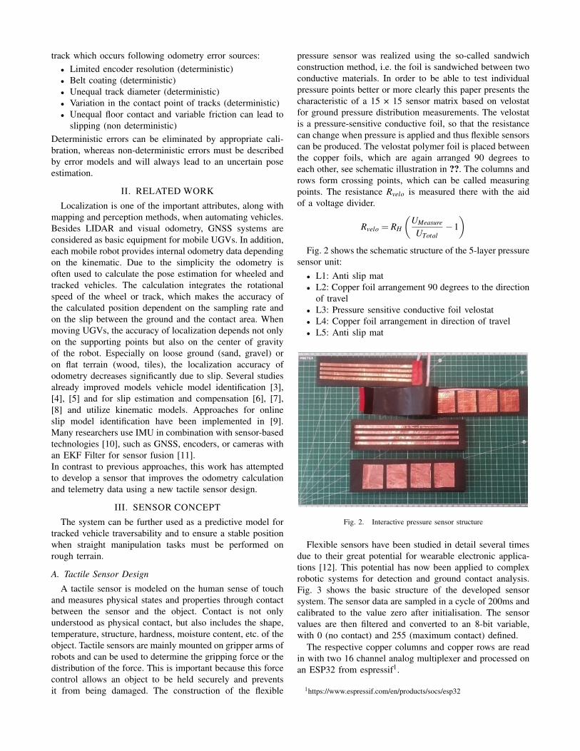
pressure sensor was realized using the so-called sandwichconstruction method, i.e. the foil is sandwiched between twoconductive materials. In order to be able to test individualpressure points better or more clearly this paper presents thecharacteristic of a 15 × 15 sensor matrix based on velostatfor ground pressure distribution measurements. The velostatis a pressure-sensitive conductive foil, so that the resistancecan change when pressure is applied and thus flexible sensorscan be produced. The velostat polymer foil is placed betweenthe copper foils, which are again arranged 90 degrees toeach other, see schematic illustration in ??. The columns androws form crossing points, which can be called measuringpoints. The resistance Rvelo is measured there with the aidof a voltage divider.
Rvelo = RH
(UMeasure
UTotal−1)
Fig. 2 shows the schematic structure of the 5-layer pressuresensor unit:• L1: Anti slip mat• L2: Copper foil arrangement 90 degrees to the direction
of travel• L3: Pressure sensitive conductive foil velostat• L4: Copper foil arrangement in direction of travel• L5: Anti slip mat
Fig. 2. Interactive pressure sensor structure
Flexible sensors have been studied in detail several timesdue to their great potential for wearable electronic applica-tions [12]. This potential has now been applied to complexrobotic systems for detection and ground contact analysis.Fig. 3 shows the basic structure of the developed sensorsystem. The sensor data are sampled in a cycle of 200ms andcalibrated to the value zero after initialisation. The sensorvalues are then filtered and converted to an 8-bit variable,with 0 (no contact) and 255 (maximum contact) defined.
The respective copper columns and copper rows are readin with two 16 channel analog multiplexer and processed onan ESP32 from espressif1.
1https://www.espressif.com/en/products/socs/esp32

Fig. 3. Overview of signal processing and flexible pressure sensor structure
Fig. 4. Electrical circuit
The 16-channel analog-digital multiplexer boards can beused when there are many analog inputs in a circuit, as inthe case with the force sensor for the centre drives (15x15matrix). In this case, one of these inputs must be selected andprocessed each time. This multiplexer can be used to select16 analogue inputs. There are four S0-3 pins that set one ofthe analog inputs as an output on the SIG pin by enteringcorresponding values, see fig. 4.
IV. METHOD
A. Robot model and MARC Payload
The developed rescue robot offers the possibility of indi-vidual configuration of sensor and actuator modules. Thesemodules are automatically recognised and the current con-figuration is specified in the XML-based robot descriptionfile. This modular design has the advantage that the robotcan be optimally configured and equipped for the respectiveapplication in a very short time [13]. The robot base and thealready developed modules are each stored with a configu-ration file in which the mass, dimensions, centre of gravitymatrix and collision model are specified.
B. Stability metrics
Based on the robot and payload configuration file thisconcept incorporates a model to measure the current vehicleroll dynamics, the current center of mass (CoM) from theentire robot system, the stability index (SI), inertia measure-ment unit data and the vehicle rollover propensity (MK). TheCoM calculation reads the robot description from the ROSUnified Robot Description Format (URDF) parameter server
and calculate the total mass of robot system. In the loopit calculates part of CoM equation depending on links andtransform the point at which the distribution of mass is equalin all directions which does not depend on gravitational field.The resulting Zero-Moment Point (ZMP) prediction providesa direct measure of the vehicle stability index (SI).
Fig. 5. Skeleton of the robot
TABLE IVEHCILE GEOMETRY PARAMETERS
α current flipper angle frontβ current flipper angle frontsi center of mass si=1...3 chassis and flippersFi weight forces Fi=1...3 chassis and flippersfs CoM distance flipper from pivot pointl length of robot chassis in x-direction
lsx CoM distance chassis from coordinate system in x-directionlsz CoM distance chassis from coordinate system in z-directionmF mass of flippermR mass of chassismT total mass of robotAs ground contact area per side (s)ls track lengthb vehicle widthp pressure as uniform normal pressure distributionc apparent cohesionφ angle of internal shearing resistance of terrain
kc,kφ pressure sinkage parametern exponent of deformation
ωs pressure sinkage parameterz sinkage
np number of periods
IMU-Data: A built-in IMU (Inertial Measurement Unit)can provide sufficient information about the body’s specificforce, angular rate and orientation based on acceleration,gyroscope and magnetometer data.CoM: The center of mass of the robot base including bothflippers without manipulator and sensor module can becalculated by
−→CoM =
xsyszs
=1
∑∞i=1 mi
x1y1z1
m1 +
x2y2z2
m2 + · · ·
=1
mR +2 ·mF
mR · lsx +mF · (l + fs · (cosβ − cosα))(mR +2 ·mF) · lsy
mR · lsz +mF · fs · (sinα + sinβ )
(1)

The tilting moment MK and the stability torque MS for therear are
F2 · fs cosα︸ ︷︷ ︸MK
< F1 · lsx +F3 · (l + fs cosβ︸ ︷︷ ︸MS
) (2)
respectively for the front
F3 · fs cosβ︸ ︷︷ ︸MK
< F1 · (l− lsx)+F2 · (l + fs cosα︸ ︷︷ ︸MS
) (3)
SI: Hence, the stability index (SI) is given by
SI =MS
MK> 1 (4)
C. Previous approaches for kinematic and probabilistic ter-rain and motion modelling
For field robot applications the terrain characterizationis essential to model the pressure-sinkage relationship forhomogeneous terrain proposed by Bekker [14]
p =
(k′c
b+ kφ
)zn
or with a newer equation from Reece [15]
p = (ck′c + γsbk
′φ )( z
b
)n
Depending on the designed tracks a sinusoidal pressuredistribution can be modeled as [16]
p =mT
bls
(1+ cos
2npπxl
)A general approach for the sinking as resistance to motion
is given by
z0 =
(p
kcb + kφ
)1/n
=
( mTbls
kcb + kφ
)1/n
A uniform pressure distribution can be calculated for theterrain compaction Rc with
Rc =1
(n+1)b1/n(
kcb + kφ
)1/n
(mT
l
)(n+1)/n
In this paper, we propose an kinematic model for ICRand extended odometry prediction based on the detection ofsupport points for tracked vehicles. To improve the accuracyfor tracked vehicles in such environments, the paper focuseson estimating the interaction between a vehicle and theground. Modeling odometry estimation depends on manyterrain-specific parameters in addition to robot parameters,see table I. Based on [16] a skid-steering model for asimplified analysis of the turning behaviour of a trackedvehicles is used. The maximum tractive effort Tmax forvehicles with tracks is defined with the parameters in table I
Fmax = Asc+mT tanφ
The following equation indicates a uniform normal pres-sure distribution and the total tractive effort of a track thatis determined by
Fs = b∫ t
0
(c+
mT
blstanφ
)(1− e−
ixK )dx
= (Asc+mT tanφ)
[1− K
ils(1− e−
ilsK )
]which expresses the relationship among track slip, terrainvalues [16], vehicle geometry parameters and tractive effort.The previous analysis is applicable for predicting the tractiveeffort of tracked drive systems with uniform normal pressuredistribution, which is rarely uniform in practical applications.Therefore, the developed area sensor can be used to evaluatethe effect of normal multipeak pressure distribution.
D. Approaches for improved ICR location modelsIn contrast to the formalism for terrain description and
motion modelling according the previous chapter, this paperattempts to predict vehicle motion by calculating the ICRof the track relative to the ground in order to measureinstantaneous loads by usage of the introduced pressuresensor above. Conventional approaches are based on purelykinematic considerations as described in Fig. 6. The ICR
Fig. 6. Kinematics - Uniform Pressure Distribution
and the driving velocity vectors always lie in the XY planeof the body-fixed coordinate system (red), which is equalto the xy plane of the inertial coordinate system in Fig. 6.The position of the ICR results from the intersection of theCoM horizontal and the connecting straight line of the twovelocity vectors X = k ·Y +d, i.e. the ICR is the zero pointfrom the latter. Considering the velocities Vl and Vr as wellas the distance a,
Vl = k · (−a)+d Vr = k ·a+d (5)
the corresponding linear equation in the body-fixed coordi-nate system is calculated as follows
k =−Vl−Vr
2 ·ad =
Vl +Vr
2(6)
X =−Vl−Vr
2 ·a·Y +
Vl +Vr
2(7)
The zero of equation (7) coincides with the ICR. Hence,
X(RICR,Y ) = 0 =−Vl−Vr
2 ·a·RICR,Y +
Vl +Vr
2(8)

RICR,Y = a · Vl +Vr
Vl−Vr(9)
Finally the associated mathematical formulation of the ICRin relation to the body-fixed reference coordinate system isgiven by
−→RICR =
(RICR,XRICR,Y
)=
(0
a · Vl+VrVl−Vr
)(10)
Weaknesses of this method become apparent in the case ofuneven distribution of the contact load as well as increasedslip between the belt and the environment. For example,when driving over an obstacle such as a wooden beam. Inthis case, the points of application of the velocity vectors canno longer be trivially assumed to be at the level of the CoM.This should be illustrated with Fig. 7. In this example, the
Fig. 7. Kinematics - Uneven Pressure Distribution
left velocity vector shifts forward due to the obstacle ahead.Thus, the linear equation is calculated by
Vl +a2 = k · (−a1)+d Vr = k ·a+d (11)
k =−Vl−Vr +a2
a+a1d =Vr +a · Vl−Vr +a2
a+a1(12)
X =−Vl−Vr +a2
a+a1·Y +Vr +a · Vl−Vr +a2
a+a1(13)
Hence, the Y-distance of the ICR is obtained by
X(RICR,Y ) = 0 =−Vl−Vr +a2
a+a1·RICR,Y +Vr +a · Vl−Vr +a2
a+a1(14)
RICR,Y = a+Vr · (a+a1)
Vl−Vr +a2(15)
and the enhanced mathematical description of the ICR reads
−→RICR =
(RICR,XRICR,Y
)=
(0
a+ Vr ·(a+a1)Vl−Vr+a2
)(16)
At this point it should be noted again that the ICR mustalways lie within the XY plane of the body-fixed coordinatesystem, but this no longer coincides with the xy plane ofthe inertial system. Extending the non-uniform load to theright track of the robot by using the parameters a3 and a4instead of a, the procedure analogous to (11)-(16) leads tothe final/general approach of calculating the ICR.
−→RICR =
(RICR,XRICR,Y
)=
(0
a3 +(Vr+a4)·(a1+a3)
Vl−Vr+a2−a4
)(17)
Conventional models do not offer the possibility todetermine the unknown dimensions a1, a2, a3 and a4.Deviating from this, the integration of the measurementdata of the pressure sensor enables the use of the improvedmodel (17) for determining the points of contact of bothtracks. This is achieved by calculating the center of gravityof the two tracks separately, using the measurement data ofthe pressure sensor and the local coordinates (x,y) of eachof the 15x15 measurement points.
V. EXPERIMENTAL RESULTS
The sensor concept was tested and evaluated on differentgrounds and terrains. The experiments were based on theemerging standard test method apparatuses for responserobots of the RoboCup Rescue League [17]. These testmethods play an important role in the evaluation process ofmobile UGVs and give participants, users and first respon-ders a quick overview of how the individual robot systemsperform in the areas of manoeuvring, mobility, dexterity andexploration [18],[19]. The proposed sensor concept providesthe feedback about the pressure distribution and the local-ization of these pressure or support points. In addition tothe distribution of the ground contact, the visualisations alsoshow the centre of gravity of the respective area sensor (seeblack dot).
A. Flat Environment and Gravel
Most of the time indoor explorations are usually done onflat terrain or at hall transitions there are usually ledges oredge transitions.
Fig. 8. Flat Environment
Fig. 8 perfectly illustrates the idea of the improved math-ematical model for ICR determination using pressure sensorfeedback. As already explained, the points of applicationof the velocity vectors corresponding to the environmentare determined separately for each track. This is done bycalculating the weighted centre of gravity per track. For this,one uses the individual measurement data as well as theircorresponding local coordinates (x,y) of the 15x15 pressuresensor. The results of this calculation, i.e. the points ofapplication of the velocity vectors, are shown throughoutthis chapter as black points per track. For approximately

uniformly distributed loads (Fig. 8 left), conventional ap-proaches as described with Fig. 6 are sufficient, since thevelocity vectors hardly deviate from the theoretical idealconsideration. For unevenly distributed pressure loads (Fig.8/10 right), the use of the pressure sensor and the associateddetermination of the contact position offers an alternativeway to predict the robot position (improved robot odometry)during rotations and advanced maneuvering.
In addition to solid surfaces, tests were also carried outon loose surfaces such as coarse gravel.
Fig. 9. Gravel
B. Bars
Bars are basic elements for testing the mobility of rescuerobots on simple terrain. These objects can also be used asdebris to test manipulation at the same time.
Fig. 10. Pressure distribution on bars
C. Hurdles and Stairs
Rescue robots will be tested to drive over terrain withmedium to hard difficulty. Two 10 cm high rolling tubeobstacles on top of each other for climbing up and downare actually no longer so easy to overcome for wheel-driven
robots and already require a more all-terrain robot here. 45degree stairs are also part of the test methods which are partlyblocked with debris in the competitions.
Fig. 11. Hurdles and Stairs
Fig. 11 above illustrates the contact points in the frontarea of the pressure sensor. These are shifted backwardsaccordingly during forward movement over hurdles. Fig. 11below shows that different load situations are possible withstairs. On the left, it shows a moderate pressure distributionin the front and rear area of the pressure sensor. During theclimb, however, local load peaks can also be expected dueto one single step (right).
D. Different Terrain Conditions
During search and rescue applications, mobile robots areconfronted with different terrain conditions. In order tosimulate these with regard to sensor suitability, a further testcourse is being set up. To keep the track very common itincludes obstacles and unevenness consisting of conventionalbricks and wooden stairs, see Fig. 12 and Fig. 13. The appro-priate sensor data are also shown graphically here, analogousto the preceding subsections of experimental results above.

Fig. 12. Different Terrain Conditions (1)
Fig. 13. Different Terrain Conditions (2)
VI. DISCUSSION AND FUTURE WORK
In this paper a tactile sensor system for tracked vehiclesespecially rescue robots is presented to improve the predic-tion of the resulting track forces and odometry calculationfor tracked vehicles. In contrast to terrain descriptive for-mulations, the current contact force distribution is directlydetected by this sensor system and can be used as a predictivemodel for tracked vehicle traversability in rough terrain. Inaddition to the feedback for the contact points an odometrycalculation is applied to estimate the ICR locations of trackedvehicles in real time. Experimental results indicates that theproposed sensor system improves the traversability analysisand furthermore can be used for stability predictions of thesystem. In combination with online monitoring of the CoMduring manipulation tasks in rough terrain safe operation andexecution can be ensured.
A planned vehicle dynamic slip model for rough terrainwhich provides a more accurate prediction of longitudinaland lateral dynamics and a model for the distribution ofvertical stresses for vehicle motion will be extended toinclude these attributes in future work.
REFERENCES
[1] M. Hutter, C. Gehring, A. Lauber, F. Gunther, C. D. Bellicoso,V. Tsounis, P. Fankhauser, R. Diethelm, S. Bachmann, M. Blosch,et al., “Anymal-toward legged robots for harsh environments,” Ad-vanced Robotics, vol. 31, no. 17, pp. 918–931, 2017.
[2] X. A. Wu, T. M. Huh, R. Mukherjee, and M. Cutkosky, “Integratedground reaction force sensing and terrain classification for smalllegged robots,” IEEE Robotics and Automation Letters, vol. 1, no. 2,pp. 1125–1132, 2016.
[3] N. Seegmiller, F. Rogers-Marcovitz, G. Miller, and A. Kelly, “Vehiclemodel identification by integrated prediction error minimization,” TheInternational Journal of Robotics Research, vol. 32, no. 8, pp. 912–931, 2013.
[4] N. Seegmiller, F. Rogers-Marcovitz, G. Miller, and A. Kelly, “A unifiedperturbative dynamics approach to online vehicle model identifica-tion,” in Robotics Research, pp. 585–601, Springer, 2017.
[5] J. Jiao, L. Sun, W. Kong, Y. Zhang, Y. Qiao, and C. Yuan, “A slidingparameter estimation method based on ukf for agricultural trackedrobot,” in The 2014 2nd International Conference on Systems andInformatics (ICSAI 2014), pp. 277–282, IEEE, 2014.
[6] G. Yamauchi, K. Nagatani, T. Hashimoto, and K. Fujino, “Slip-compensated odometry for tracked vehicle on loose and weak slope,”Robomech Journal, vol. 4, no. 1, pp. 1–11, 2017.
[7] J. Pentzer, S. Brennan, and K. Reichard, “Model-based prediction ofskid-steer robot kinematics using online estimation of track instanta-neous centers of rotation,” Journal of Field Robotics, vol. 31, no. 3,pp. 455–476, 2014.
[8] G. Yamauchi, D. Suzuki, and K. Nagatani, “Online slip parameterestimation for tracked vehicle odometry on loose slope,” in 2016 IEEEInternational Symposium on Safety, Security, and Rescue Robotics(SSRR), pp. 227–232, IEEE, 2016.
[9] H. Lu, G. Xiong, and K. Guo, “Motion predicting of autonomoustracked vehicles with online slip model identification,” MathematicalProblems in Engineering, vol. 2016, 2016.
[10] J. Yi, J. Zhang, D. Song, and S. Jayasuriya, “Imu-based localizationand slip estimation for skid-steered mobile robots,” in 2007 IEEE/RSJInternational Conference on Intelligent Robots and Systems, pp. 2845–2850, IEEE, 2007.
[11] H. Zhao and Z. Wang, “Motion measurement using inertial sensors,ultrasonic sensors, and magnetometers with extended kalman filter fordata fusion,” IEEE Sensors Journal, vol. 12, no. 5, pp. 943–953, 2011.
[12] S.-T. Han, H. Peng, Q. Sun, S. Venkatesh, K.-S. Chung, S. C. Lau,Y. Zhou, and V. Roy, “An overview of the development of flexiblesensors,” Advanced materials, vol. 29, no. 33, p. 1700375, 2017.
[13] R. Edlinger and A. Nuechter, “Marc-modular autonomous adaptablerobot concept,” in 2019 IEEE International Symposium on Safety,Security, and Rescue Robotics (SSRR), pp. 1–7, IEEE, 2019.
[14] M. Bekker, “Introduction to terrain-vehicle systems,” University ofMichigan Press, vol. Ann Arbor, 1969.
[15] A. R. Reece, “Principles of soil-vehicle mechanics,” Proc. Institutionof Mechanical Engineers, vol. part 2A, 1965.
[16] J. Y. Wong, Theory of ground vehicles. John Wiley & Sons, 2008.[17] R. Sheh, A. Jacoff, A.-M. Virts, T. Kimura, J. Pellenz, S. Schwertfeger,
and J. Suthakorn, “Advancing the state of urban search and rescuerobotics through the robocuprescue robot league competition,” in Fieldand service robotics, pp. 127–142, Springer, 2014.
[18] T. Kimura, M. Okugawa, K. Oogane, Y. Ohtsubo, M. Shimizu,T. Takahashi, and S. Tadokoro, “Competition task development forresponse robot innovation in world robot summit,” in 2017 IEEEInternational Symposium on Safety, Security and Rescue Robotics(SSRR), pp. 129–130, IEEE, 2017.
[19] A. Jacoff, R. Candell, A. Downs, H.-M. Huang, K. Kimble, K. Saidi,R. Sheh, and A. Virts, “Events for the application of measurementscience to evaluate ground, aerial, and aquatic robots,” in 2017 IEEEInternational Symposium on Safety, Security and Rescue Robotics(SSRR), pp. 131–132, IEEE, 2017.