Stability Analysis of the Red River Dike: The Past to the ...
6
14 Plaxis Bulletin l Spring issue 2013 l www.plaxis.nl » The Red River (known as Song Hong in Vietnamese) flows from the mountain areas of Southern China to the Gulf of Tonkin (East Sea) with a total length of over 1150km (the length in Vietnam’s area is about 510km), as seen in Figure 1. The River is the biggest one in the northern part of Vietnam with the total dike length of nearly 1700km that take up more than a half of the length of the dike systems of the delta. The dikes are divided into different parts due to their specifically protective functions, and each part will follow a different level of safety. In the Hanoi area, the length of dikes of grade 1 and “special* 1 ” is around 250km in a total of 470km (DDMFC, 2009), (see Figure 2). In this part, four periods of dike development will be discussed to give readers an overview of dike rehabilitation for hundreds of years ago. The first period of the stability analysis is the empirical period of Vietnam which started in the 11th century, when the first dikes were built, till 1890s. However, the significant progress in flood protection was only made from the beginning of the 19th century in the Nguyen dynasties. At that time, people knew how to measure the height of flood water level and strengthen the dike system after each flood. As a result, the dike crests were increased each year after dike breaches and floods, without any prediction for the next levels of The Red River delta is located in Northern Vietnam with an area of around 15,500 km2 and a population of nearly 20 million people. The delta is protected by approximately 3000 km of dikes which are classified into four grades from III, II, I to “special”; and each dike type attains a different level of safety. In the past, most of the dikes, which were not high enough, failed mainly due to overflowing; therefore the area was usually threatened with flooding. Nowadays, as a result of many measures that have been imposed in the delta such as strengthening the dike systems, constructing the dams in the upstream river for multiple purposes, the flood risk in the area is reduced significantly. In this paper, the authors compare the different levels of safety in the past with those of the present situation by using Plaxis code that includes several material models. Stability Analysis of the Red River Dike: The Past to the Present Pham Quang Tu, P.H.A.J.M van Gelder, Technical University of Delft, The Netherlands Trinh Minh Thub, Hanoi Water Resources University Figure 1: Red river basin (from Khoi [2010]) *1 “special” grade is used in Vietnam dike system as the top grade which is more important than the grade 1(for instance, the dike system in Hanoi area, the capital of Vietnam)
Transcript of Stability Analysis of the Red River Dike: The Past to the ...

14 Plaxis Bulletin l Spring issue 2013 l www.plaxis.nl
»The Red River (known as Song Hong in Vietnamese) flows from the mountain areas
of Southern China to the Gulf of Tonkin (East Sea) with a total length of over 1150km (the length in Vietnam’s area is about 510km), as seen in Figure 1. The River is the biggest one in the northern part of Vietnam with the total dike length of nearly 1700km that take up more than a half of the length of the dike systems of the delta. The dikes are divided into different parts due to their specifically protective functions, and each part will follow a different level of safety. In the Hanoi area, the length of dikes of grade 1 and “special*1” is around 250km in a total of 470km (DDMFC, 2009), (see Figure 2). In this part, four periods of dike development will be discussed to give readers an overview of dike rehabilitation for hundreds of years ago.
The first period of the stability analysis is the empirical period of Vietnam which started in the 11th century, when the first dikes were built, till 1890s. However, the significant progress in flood protection was only made from the beginning of the 19th century in the Nguyen dynasties. At that time, people knew how to measure the height of flood water level and strengthen the dike system after each flood. As a result, the dike crests were increased each year after dike breaches and floods, without any prediction for the next levels of
The Red River delta is located in Northern Vietnam with an area of around 15,500 km2 and a population of nearly 20 million people. The delta is protected by approximately 3000 km of dikes which are classified into four grades from III, II, I to “special”; and each dike type attains a different level of safety. In the past, most of the dikes, which were not high enough, failed mainly due to overflowing; therefore the area was usually threatened with flooding. Nowadays, as a result of many measures that have been imposed in the delta such as strengthening the dike systems, constructing the dams in the upstream river for multiple purposes, the flood risk in the area is reduced significantly. In this paper, the authors compare the different levels of safety in the past with those of the present situation by using Plaxis code that includes several material models.
Stability Analysis of the Red River Dike: The Past to the Present
Pham Quang Tu, P.H.A.J.M van Gelder, Technical University of Delft, The NetherlandsTrinh Minh Thub, Hanoi Water Resources University
Figure 1: Red river basin (from Khoi [2010])
*1 “special” grade is used in Vietnam dike system as the top grade which is more important than the grade 1(for instance, the dike system in Hanoi area, the capital of Vietnam)

www.plaxis.nl l Spring issue 2013 l Plaxis Bulletin 15
safety. In this period the last geometry of dike and the severity of the typical flood in the year 1893 were opted for the stability analysis. There were 38 years with dike failures during this period causing serious damage to the economy and fatalities (GDM, 1995), meanwhile in the 20th century, only 8 years with dike failure were observed.
The second period of the analysis is from 1890s to 1945 when France fully established their ruling in Vietnam. After assisting the Nguyen dynasties in governing the whole country, the French widely exploited the natural resources; as a result, infrastructures were developed for their purposes. At that time, French engineers were requested to transfer strategically their experiences of flood protection in Hanoi, for instance, the 1st and the 2nd dike program, under the supervision of the Dikes Commission ( see GDM, 1995; Phan, 1985). Consequently, there were some noticeable progresses in flood mitigation during this time; for instance, the increase of the dike crest from 10.5m to 13.0m and the construction of Day Dam for flood diversion to lower the water level in Hanoi area, etc.
Table 1: Flood water level
Year Flood water level (m) Flood duration (days) Note*
1893 10.5 (13)* 7 9
1915 12 12 10.5
1945 13.5 5 10.5
1971 14.6 5 11.5
1996 12.98 23 11.5
Future*2 14.9 16 11.5
Figure 3: Probablility distribution of maximum water level
Figure 2: Red river around Hanoi area
*2 Flood duration is calculated following a threshold level (here, alarm level 3~11,5m at Hanoi)

16 Plaxis Bulletin l Spring issue 2013 l www.plaxis.nl
Figure 4: Typical dike strengthen strategies
Figure 5: Typical geotechnical profiles
Ground level Ground level Ground level Ground level GL + 7.9mGround level
The third period, the Vietnam war, spread from 1945 till 1975 which resulted in the anomalies of river dikes. At that time, the dikes could be bomb targets or were excavated to slow down enemy assaults. Although much effort spent on the rehabilitation of the whole dike system of the Red River Delta, they were still facing a high flood risk, and even the rehabilitation works had been undertaken for the whole dike system in the Red River Delta. Additionally, the attempts to heightening and strengthening the dike system such as millions of man-days, and cubic meter of earthworks, have been done in this period, which made it to the top of amount of dike rehabilitation work (see FPD, 2000). In terms of dike engineering, the anomalies of dike embankment did not only come from its very construction, but also from such social activities.
The last period for the analysis is the Renovation-of-Economy time (known as “Doi Moi” in Vietnam) from 1986 till now. Economically, private-owned enterprises were established and equally treated as state-owned ones. As a result, new technologies were applied to dike safety in the projects funded by the Asian Development Bank (ADB) or by local governments. The safety level of the flood defence system has been improved significantly due to the application of effective measures such as planting and protecting forests in upper basins, constructing dams and reservoirs to store water, strengthening dikes, and raising awareness of flood protection in the public. In short, the Red River dikes are now able to withstand a flood frequency from 1/250 year to 1/500 year comparing to 1/50 year in the third period (Ha, 2010).
During the past hundred years, the overflowing and the resulting erosion of inner slope, that came from the limited height of dike system, caused many dike failures. In times from the empirical period until now the dike embankment compaction ratio, K*3, has varied considerably. In addition, soil properties and their distribution also changed underneath the dikes. These two aspects play an important role in dike safety assessment, particularly for flood wave durations. In this paper, dike stability is studied following a deterministic approach taking into account first the historical data to illustrate different stress states and water levels, and second different soil models.
Input DataThe selected location in this case study is 10km upstream of Hanoi Old quarter, namely Lien Mac (in Vietnamese). In 1915, there was a serious dike breach at this dike section caused by overflowing-the main failure mechanism (see Local Dike Board No.3, 1971-2010).
Firstly, the hydraulic boundary condition is considered with the statistical data of over 100 years. After that, the maximum water level and flood duration are fitted to the theoretical distributions. The water levels in the calculations have been chosen following the historical data of the typical flood waves in the years 1893, 1915, 1945 and 1971. It could be seen from Figure 3 that the water level was maximum at 14.6m in 1971, and equalled a flood return period of 1/50 year. Additionally, flood mitigating measures have been
carried out, such as planting trees in the upstream basin, constructing reservoirs for many multiple purposes, strengthening dike systems, and applying flood diversion. A rising level of around 14.9m*4, equivalent to a flood frequency of 1/500 year, will be considered for the near future (for more details, see Table 1).
Secondly, dike geometry was collected from the local dike boards and historical documents. In the 19th century-empirical period-there were no drawings of dike cross sections due to the limitations of both scientific knowledge and poor archives of works. In the period dominated by the French, the dike dimensions were formulated based on historical documents and updated with research works (Phan, 1985; Gauthier, 1930; Monsieur and Dominique, 1991). The data including documents of dikes have been properly protected, so all typical sections relating to each dike program are quite clear and available now. The strategies of dike rehabilitation are described geometrically in Figure 4.
Thirdly, from geotechnical investigations, the profiles of soil are illustrated with different typical combinations. Nguyen (1999) summarized the four possible cross sections for analysis in the project of Red River dike rehabilitation. Tran (2012) also recommended five types of ground conditions for the assessment of the Red River dikes. In fact, both the studies are nearly similar, although the latter described more clearly the influence of the silty fine sand layer to the dike stability. In this paper, the authors take in to account the 1st profile for
calculation; the 4th and the 5th types seem to be more dangerous for dike embankments, but these profiles are vanished from the study area and they will be discussed in another report (see Figure 5).Finally, soil properties were selected from the report of Geotechnical investigation, which were carried out in 1994 for the ADB project (HEC1, 1994). The dike embankment is represented by different compaction ratios which is assumed varying from K < 0.80 (in 1890s) to K~ 0.95 (currently). The soils of embankment have been remoulded in the laboratory with the mentioned compaction ratios, then the strength and the compression were determined by direct shear test and oedometer test. In fact, the soil parameters (of layers 2b, 7, 8 following HEC1 (1994)) could not be determined at the construction period, for instance during 1890s, 1915, 1945, etc. It is assumed that the changes of soil parameters are disregarded in this case study.
Strength and stiffness of soils may be influenced by different stress states that resulted in actual loading progresses. In this case, both Mohr - Coulomb (MC) and Hardening Soil (HS) models were applied, and parameters were selected following Table 2 and 3.
Calculation Phases, Results, and DiscussionFollowing the manual of Plaxis 2D-2011 (Brinkgreve, 2011) these problems could be analysed by the Plaxis finite element code which includes multiple choices for material models, construction stages, and calculation types, etc. However, it is hard to model stress states from
*3 Compaction ratio K = gdry/gmax where, gdry is gdry density of soil; gmax is the maximum density of soil, which is found by plotting a density - moisture curve in compaction test in laboratory (ASTM D698 & ASTM D1557).*4 Predicted results of flood frequency of 1/500 year, (Khoi, 2010)
Stability Analysis of the Red River Dike: The Past to the Present

www.plaxis.nl l Spring issue 2013 l Plaxis Bulletin 17
Table 2: Soil parameters for Mohr - Coulomb model
Identification Unit Dikes1880 Clay1 Clay2 Sand Dikes1945 Dikes 2000
Drainage type Undrained (A) Undrained (A) Undrained (A) Drained Undrained (A) Undrained (A)
gunsat kN/m3 17 18.5 19.5 19 18 18.7
gsat kN/m3 17.5 19 20 19 18.7 19.3
E kN/m2 3000 4500 7000 12000 3800 4500
n(nu) 0.33 0.3 0.28 0.33 0.32 0.27
G kN/m2 1128 1731 2734 4511 1439 1772
Eoed kN/m2 4445 6058 8949 17780 5438 5623
cref kN/m2 9 12 20 0.1 12 18
f (phi) deg 7 9 12 28 10 12
Flow model Van Genuchten Van Genuchten Van Genuchten Van Genuchten Van Genuchten Van Genuchten
Soil type Silty clay loam Medium fine Fine Sand Silty clay loam Silty clay loam
kx m/day 0.05 0.014 0.0003 1.27 0.04 0.03
ky m/day 0.05 0.014 0.0003 1.27 0.04 0.03
Table 3: Soil parameters for Hardening Soil model
Notes: The data used in tables 2 & 3 are adapted from HEC1 [1994]
Identification Unit Dikes1880 Clay1 Clay2 Sand Dikes1945 Dikes 2000
Drainage type Undrained (A) Undrained (A) Undrained (A) Drained Undrained Undrained (A)
gunsat kN/m3 17 18.5 19.5 19 18 18.7
gsat kN/m3 17.5 19 20 19 18.7 19.3
Eref50 kN/m2 3000 3150 5500 7500 4400 5500
Erefoed kN/m2 3400 5500 7500 7800 4300 6000
Erefur kN/m2 10000 16500 23500 20000 13000 17000
power (m) 0.5 0.5 0.5 0.5 0.5 0.5
cref kN/m2 9 12 20 0.1 12 15
f(phi) deg 7 9 12 28 10 12
Flow model Van Genuchten Van Genuchten Van Genuchten Van Genuchten Van Genuchten Van Genuchten
kx m/day 0.05 0.014 0.0003 1.27 0.04 0.03
ky m/day 0.05 0.014 0.0003 1.27 0.04 0.03
Stability Analysis of the Red River Dike: The Past to the Present
a hundred years ago; here we ignored the time interval in each calculation phase, and we opted for undrained behaviour as the drainage type. Time dependent conditions in each flooding season are considered by transient analysis. The calculation phases are illustrated below.
• Initial: Gravity loading, the initial conditions have been calculated and the classical mode is chosen for calculation;
• Phase 1: The 1st dike stage of construction follows the dike geometry of 1893; the new dike is built up and the ground water level is ap-proximately set on the surface level because the earthwork had been carried out in dry seasons;
• Phase 2: The high water level in 1893, which is set at 10.5m and transient flow is modelled for the analysis with the flood duration of 7 days;
• Phase 3: The analysis of dike safety has been used to determine the factor of safety in the flood in 1893.
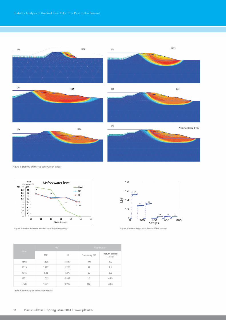
The procedures are repeated from phase 1 to 3 for each flood in 1915, 1945, and 1971 with water level and flood duration given in Table 1. . Figure 6 shows the results of the safety calculation phases, and the plastic zones enlarge depending on both the dike geometry and the flood water levels. The phreatic levels reach the critical situation in most cases, and the dike embankments were saturated. The level of dike crest has increased many times with different construction methods (Phan, 1985). In this paper, only four different geometry of dikes are selected because they were dealing with the typical flood waves and the major project of dike rehabilitation. Dike failure was observed twice in the year 1915 at the study location, comparing to eight cases of dike failure during the 20th century (Ha, 2010), and where the overflowing was the dominant mechanism of failure. Table 4 and Figure 7 show that we have the maximum of dike safety in 1893
with the level of dike crest of 10.5m, and the safety factor (Msf) minimizes at the predicted situation with a flood frequency of 1/500 year. However, in terms of flood management, the dike in the year 1893 might be safe at the water level frequency of 1/1 year (see Figure 3). It means that if there is a flood with a higher water level of 10.5m, dikes could failed by the overflowing and erosion of the inner slope, even if its safety factor reaches 1.54. In 1971, the dike could be able to withstand in the critical states, e.g., Msf ~ 1. It showed reasonable evidence for dike assessments around Hanoi at that time with some dike sections at the birth of collapse (see FPD, 2000). At the predicted flood level of 1/500 year, the water level is not raised freely because the Red River discharge is redistributed by the reservoir systems at the upstream rivers. However, the flood duration increases dramatically, from 5 days (in 1893) to 16 days (in the predicted flood of 1/500 year) and dikes are also at the risk of critical situations. If
18 Plaxis Bulletin l Spring issue 2013 l www.plaxis.nl
Figure 6: Stability of dikes vs construction stages
Figure 7: Msf vs Material Models and flood frequency
Table 4: Summary of calculation results
Year
Msf Flood wave
MC HS Frequency (%)Return period
(1/year)
1893 1.538 1.549 100 1.0
1915 1.282 1.226 91 1.1
1945 1.32 1.279 20 5.0
1971 1.032 0.987 2.2 45.5
1/500 1.031 0.989 0.2 500.0
Figure 8: Msf vs steps calculation of MC model
Stability Analysis of the Red River Dike: The Past to the Present

www.plaxis.nl l Spring issue 2013 l Plaxis Bulletin 19
Stability Analysis of the Red River Dike: The Past to the Present
other failure mechanisms presented, the dike could have failed.
Comparing the material models of MC and HS, we can see from Figure 7 that the former has a higher value of Msf than that of the latter. A possible explanation is that the HS model mobilize soils strength lower than that of the MC model (Brinkgreve, 2009); in this case, HS model is preferable to application.
ConclusionsAn adequate assessment of dike safety is a complex issue that should include not only the instability but also piping and other failure mechanisms. In stability analysis, PLAXIS 2D 2011 demonstrated successfully the dike safety factor in flood waves with different construction stages. A dike location in Red River in Hanoi with historical data of dike failure is selected and the calculation results demonstrated reasonably comparing to the past observations, and dike’s stability has been significantly improved from the past until now. The dike’s stability was calculated in critical states of both the flood in 1971 (with return period of 1/50 year) and the flood frequency of 1/500 year and was found to be unsafe. In contrast, it was estimated to be safe in the flood with a return period of 1/1 year in 1893, with regard to stability only. Further research should be carried out to investigate the influences of the heterogeneity of dike embankment and subsoil data, and other related issues such partially saturated soil behaviour and advanced soil models.
AcknowledgementsThis paper is funded by the project of Upgrading the Training Capacity in Coastal Engineering of the Water Resources University of Vietnam from the Royal Netherlands Embassy in Hanoi of Vietnam, and CICAT and Hydraulic Engineering Department of TU Delft; the authors wish to thank for their support.
References• Hanoi DDMFC. Report on current condition of
river dike systems in Hanoi area before flood season 2009. Technical report, 2009.
• General Department of Meteorology GDM. His-tory of Vietnam Meteorology, Vol 1, Ministry of Natural Resources and Environment of Vietnam. Hanoi Meteorology publishing, 1995.
• Phan, K. (1985). A brief history of water manage-ment in Vietnam (in Vietnamese). Hanoi: Hanoi Social Science Publishing.
• Ha Van Khoi. Study the scientific background for un-flooded some lower area in the red river basin and Hoanglong river basin. Technical report, 2010.
• Hanoi Local Dike Board No3. General back-ground of red river dike systems in Hanoi area, board no3. Technical report, 1971.
• J Gauthier. Digues du Tonkin (Hanoi, Imprimerie D’extreme-orient). M6409 – National library of Vietnam, 1930.
• M.D Hemery. Histoire du euve rouge, gestion et amenagement d’un systeme hydraulique au tonkin des annees 1890 jusqu’a la seconde guerre mondiale, tome 1 – History of the Red River, management and Layouts of a system of hydraulic tonkin 1890s until the Second World War, Volume 1. Universite de Paris 7, 1991.
• Nguyen, C. M. Some geotechnical engineering aspects of dike in red river delta, calculation re-vitalization. In Proceeding of Geology engineer-ing and geo-environment in Vietnam, 1999.
• Tran, V. T. Study on the geological conditions of the red river dikes in Hanoi area. Technical report, 2012.
• HEC1. Geology investigation reports, Hanoi dikes improvement project. Technical report, 1994.
• R.B.J Brinkgreve. Plaxis 2D-2011 manual, vols 1:5. Plaxis BV, 2011.
• Hanoi. FPD. Hanoi - 50 years with natural hazard protection work, Flood Protection Department of Hanoi. Hanoi publishing, 2000.
• R.B.J Brinkgreve. Material models for rock and soil - Lecture note CT4360. Technical University of Delft, 2009.